
NT1865DSA - Stapler HiKOKI - Free user manual and instructions
Find the device manual for free NT1865DSA HiKOKI in PDF.


| Product Type | Cordless Finish Nailer (Stapler) |
| Model | NT1865DSA |
| Battery Voltage | 18 V (Multi-volt: 18 V / 36 V) |
| Motor Type | DC Brushless |
| Applicable Nail Gauge | 16 Ga (straight) |
| Applicable Nail Length | 25 mm to 64 mm |
| Magazine Capacity | 100 nails (2 strips) |
| Cycle Rate | 3.0 nails/second (intermittent) |
| Weight (with BSL36A18X) | 3.4 kg |
| Dimensions (H × L × W) | 342 mm × 295 mm × 104 mm |
| Firing Modes | Full sequential / Contact actuation (selectable) |
| Power Switch | Push and hold >1 sec to turn on/off; auto power-off after 30 min |
| LED Light | Automatic, illuminates tip area |
| Trigger Lock | Switch lock lever to prevent accidental firing |
| Depth Adjustment | Rotary adjuster (half-turn increments) |
| Empty-Firing Prevention | Activates when ≤10 nails remain |
| Dry-Fire Lockout | Prevents driving when magazine is empty |
| Temperature Range | Operating: -5°C to 40°C; Charging: 0°C to 50°C |
| Battery Type | HiKOKI Lithium-ion (BSL36A18X included) |
| Charger Model | UC18YSL3 (14.4–18 V) |
| Charging Time (5.0 Ah) | Approx. 32 min at 20°C |
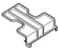
| Nose Cap | Accessory to protect workpiece surface |
| Hook | Reversible for hanging |
Frequently Asked Questions - NT1865DSA HiKOKI
User questions about NT1865DSA HiKOKI
0 question about this device. Answer the ones you know or ask your own.
Ask a new question about this device
Download the instructions for your Stapler in PDF format for free! Find your manual NT1865DSA - HiKOKI and take your electronic device back in hand. On this page are published all the documents necessary for the use of your device. NT1865DSA by HiKOKI.
USER MANUAL NT1865DSA HiKOKI
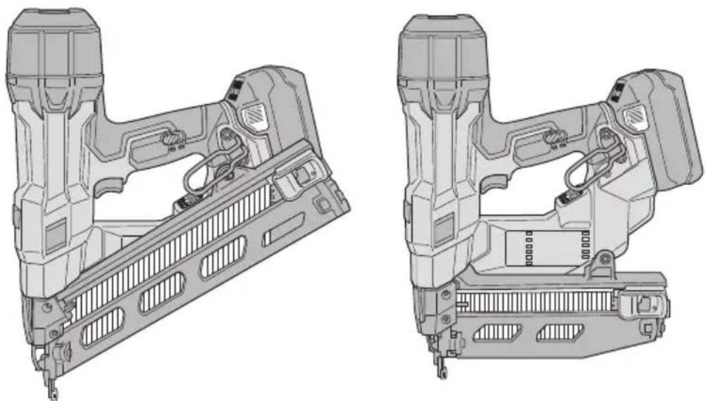
NT 1865DAA • NT 1865DSA
natural_image
Technical line drawings of two mechanical assembly components (no text or symbols)NT1865DAANT1865DSA
1
New Zealand model of NT1865DSA
2
3
4
5
6
flowchart
graph TD
    A["Device 1"] --> B["New Zealand model of NT1865DSA"]
    C["Device 2"] --> D["New Zealand model of NT1865DSA"]
    E["Device 3"] --> F["New Zealand model of NT1865DSA"]
7
8
flowchart
graph TD
    A["16"] --> B["17"]
    B --> C["14"]
    C --> D["2"]
    D --> E["3"]
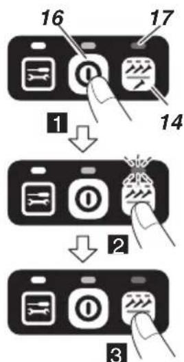
For New Zealand model of NT1865DSA specifications, nailing operation mode cannot be switched.
9
10
11 | 12
natural_image
Line drawing of hands operating a fastener with a tool, showing mechanical assembly and tool path (no text or symbols)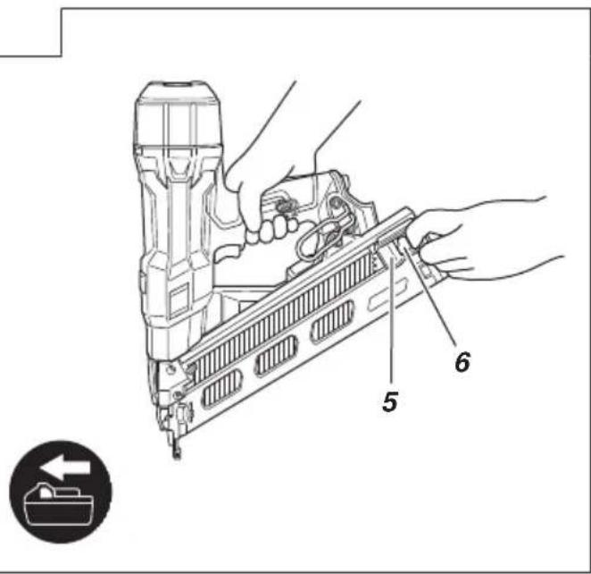
13
14
natural_image
Illustration of hands using a fastener to install a grid-patterned component, with no visible text or symbols.15
16
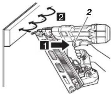
For New Zealand model of NT1865DSA specifications, operation cannot be switched over to continuous operation (push lever fire) method.
17
18
19
20
21
22
23
24
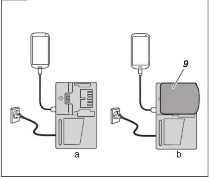
25
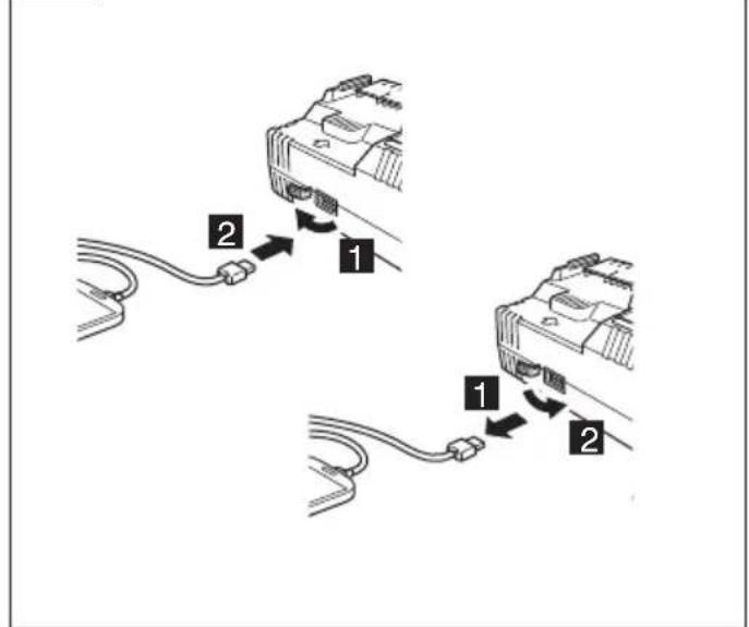
26
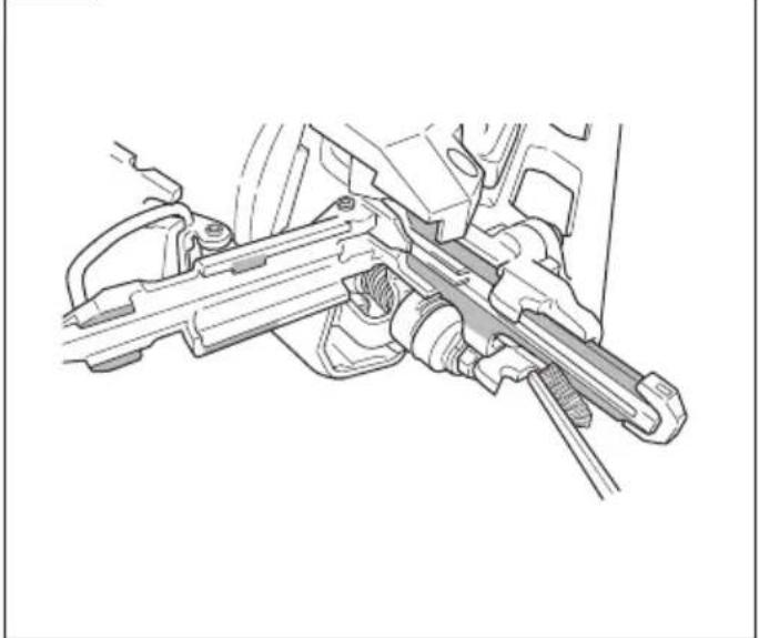
natural_image
Technical line drawing of a mechanical assembly with no visible text or symbolsGENERAL POWER TOOL SAFETY WARNINGS
WARNING
Read all safety warnings and all instructions.
Failure to follow the warnings and instructions may result in electric shock, fire and/or serious injury.
Save all warnings and instructions for future reference.
The term “power tool” in the warnings refers to your mains-operated (corded) power tool or battery-operated (cordless) power tool.
1) Work area safety
a) Keep work area clean and well lit.
Cluttered or dark areas invite accidents.
b) Do not operate power tools in explosive atmospheres, such as in the presence of flammable liquids, gases or dust.
Power tools create sparks which may ignite the dust or fumes.
c) Keep children and bystanders away while operating a power tool.
Distractions can cause you to lose control.
2) Electrical safety
a) Power tool plugs must match the outlet. Never modify the plug in any way. Do not use any adapter plugs with earthed (grounded) power tools.
Unmodified plugs and matching outlets will reduce risk of electric shock.
b) Avoid body contact with earthed or grounded surfaces, such as pipes, radiators, ranges and refrigerators.
There is an increased risk of electric shock if your body is earthed or grounded.
c) Do not expose power tools to rain or wet conditions.
Water entering a power tool will increase the risk of electric shock.
d) Do not abuse the cord. Never use the cord for carrying, pulling or unplugging the power tool. Keep cord away from heat, oil, sharp edges or moving parts.
Damaged or entangled cords increase the risk of electric shock.
e) When operating a power tool outdoors, use an extension cord suitable for outdoor use.
Use of a cord suitable for outdoor use reduces the risk of electric shock.
f) If operating a power tool in a damp location is unavoidable, use a residual current device (RCD) protected supply.
Use of an RCD reduces the risk of electric shock.
3) Personal safety
a) Stay alert, watch what you are doing and use common sense when operating a power tool. Do not use a power tool while you are tired or under the influence of drugs, alcohol or medication.
A moment of inattention while operating power tools may result in serious personal injury.
b) Use personal protective equipment. Always wear eye protection.
Protective equipment such as dust mask, non-skid safety shoes, hard hat, or hearing protection used for appropriate conditions will reduce personal injuries.
c) Prevent unintentional starting. Ensure the switch is in the off position before connecting to power source and/or battery pack, picking up or carrying the tool. Carrying power tools with your finger on the switch or energising power tools that have the switch on invites accidents.
d) Remove any adjusting key or wrench before turning the power tool on.
A wrench or a key left attached to a rotating part of the power tool may result in personal injury.
e) Do not overreach. Keep proper footing and balance at all times.
This enables better control of the power tool in unexpected situations.
f) Dress properly. Do not wear loose clothing or jewellery. Keep your hair, clothing and gloves away from moving parts.
Loose clothes, jewellery or long hair can be caught in moving parts.
g) If devices are provided for the connection of dust extraction and collection facilities, ensure these are connected and properly used.
Use of dust collection can reduce dust-related hazards.
4) Power tool use and care
a) Do not force the power tool. Use the correct power tool for your application.
The correct power tool will do the job better and safer at the rate for which it was designed.
b) Do not use the power tool if the switch does not turn it on and off.
Any power tool that cannot be controlled with the switch is dangerous and must be repaired.
c) Disconnect the plug from the power source and/or the battery pack from the power tool before making any adjustments, changing accessories, or storing power tools.
Such preventive safety measures reduce the risk of starting the power tool accidentally.
d) Store idle power tools out of the reach of children and do not allow persons unfamiliar with the power tool or these instructions to operate the power tool.
Power tools are dangerous in the hands of untrained users.
e) Maintain power tools. Check for misalignment or binding of moving parts, breakage of parts and any other condition that may affect the power tool's operation.
If damaged, have the power tool repaired before use.
Many accidents are caused by poorly maintained power tools.
f) Keep cutting tools sharp and clean.
Properly maintained cutting tools with sharp cutting edges are less likely to bind and are easier to control.
g) Use the power tool, accessories and tool bits etc. in accordance with these instructions, taking into account the working conditions and the work to be performed.
Use of the power tool for operations different from those intended could result in a hazardous situation.
5) Battery tool use and care
a) Recharge only with the charger specified by the manufacturer.
A charger that is suitable for one type of battery pack may create a risk of fire when used with another battery pack.
b) Use power tools only with specifically designated battery packs.
Use of any other battery packs may create a risk of injury and fire.
c) When battery pack is not in use, keep it away from other metal objects, like paper clips, coins, keys, nails, screws or other small metal objects, that can make a connection from one terminal to another.
Shorting the battery terminals together may cause burns or a fire.
d) Under abusive conditions, liquid may be ejected from the battery; avoid contact. If contact accidentally occurs, flush with water. If liquid contacts eyes, additionally seek medical help.
Liquid ejected from the battery may cause irritation or burns.
6) Service
a) Have your power tool serviced by a qualified repair person using only identical replacement parts.
This will ensure that the safety of the power tool is maintained.
PRECAUTION
Keep children and infirm persons away.
When not in use, tools should be stored out of reach of children and infirm persons.
-
Always assume that the tool contains fasteners. Careless handling of the nailer can result in unexpected firing of fasteners and personal injury.
-
Do not point the tool towards yourself or anyone nearby. Unexpected triggering will discharge the fastener causing an injury.
-
Do not actuate the tool unless the tool is placed firmly against the workpiece. If the tool is not in contact with the workpiece, the fastener may be deflected away from your target.
-
Disconnect the tool from the power source when the fastener jams in the tool. While removing a jammed fastener, the nailer may be accidentally activated if it is plugged in.
-
Use caution while removing a jammed fastener. The mechanism may be under compression and the fastener may be forcefully discharged while attempting to free a jammed condition.
-
Do not use this nailer for fastening electric cables. It is not designed for electric cable installation and may damage the insulation of electric cables thereby causing electric shock or fire hazards.
ADDITIONAL SAFETY WARNINGS
- Safe operation through correct usage.
This tool was designed for driving nails into wood and similar materials. Use it for its intended purpose only.
- Be careful of ignition and explosions.
Since sparks may fly during nailing, it is dangerous to use this tool near lacquer, paint, benzine, thinner, gasoline, gas, adhesives and similar inflammable substances as they may ignite or explode. Under no circumstances should this tool therefore be used in the vicinity of such inflammable material.
- Always wear eye protection (protective goggles).
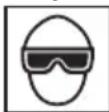
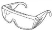
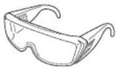
When operating the power tool, always wear eye protection, and ensure that surrounding people wear eye protection too. Eye protection should not be inferior to the specification set in AS/NZS 1337 Eye protectors for industrial applications.
The possibility of fragments of the nails that were not properly hit entering the eye is a threat to sight. Always wear eye protection while operating this tool. Use either eye protection or a wide vision mask over prescription glasses.
Employers should always enforce the use of eye protection equipment.
- Protect your ears and head.
When engaged in nailing work please wear ear mufflers and head protection. Also, depending on condition, ensure that surrounding people also wear ear mufflers and head protection. Hearing protection equipment should be of a reputable make and manufactured to an acceptable standard, for example AS/NZS 1270 Acoustics-Hearing protectors.
- Pay attention to those working close to you.
It would be very dangerous if nails that were not properly driven in should hit other people. Therefore, always pay attention to the safety of the people around you when using this tool. Always make sure that nobody's body, hands or feet are close to the nail outlet.
- Never point the nail outlet towards people.
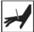
Always assume the tool contains fasteners.
If the nail outlet is pointed towards people, serious accidents may be caused if you mistakenly discharge the tool. When connecting and disconnecting the battery, during nail loading or similar operations, be sure the nail outlet is not pointed towards anyone (including yourself).
Even when no nails are loaded at all, it is dangerous to discharge the tool while pointing it at someone, so never attempt to do so. No horseplay. Respect the tool as a working implement.
- Check push lever before use.
Make sure the push lever operates properly. Never use the Nailer unless the push lever is operating properly, otherwise the Nailer could drive a fastener unexpectedly. Do not tamper with or remove the push lever, otherwise the push lever becomes inoperable.
- Choice of triggering method is important.
Read and understand section titled "HOW TO USE THE NAILER" on page 16.
-
Prior to using this product, make sure that it is operating properly in accordance with the content of "Testing the nailer" on page 15.
-
Use specified nails only.
Never use nails other than those specified and described in these instructions.
- Be careful when connecting the battery.
When connecting the battery and loading nails in order not to fire the tool by mistake, make sure of the followings.
○ Do not touch the trigger.
○ Do not allow the firing head to contact with any surface.
○ Keep the firing head down.
Strictly observe the above instructions, and always make sure that no part of the body, hands or legs is ever in front of the nail outlet.
- Do not carelessly place your finger on the trigger.
Do not place your finger on the trigger except when actually nailing. If you carry this tool or hand it to someone while having your finger on the trigger, you may inadvertently discharge a nail and thus cause an accident.
- Press the nail outlet firmly against the material to be nailed.
When driving in nails, press the nail outlet firmly against the material to be nailed. If the outlet is not applied properly, the nails may rebound.
- Keep hands and feet away from the firing head when using.
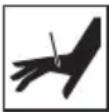
It is very dangerous for a nail to hit the hands or feet by mistake.
- Beware of the tool's kickback.
Do not approach the top of the tool with your head etc. during operation. This is dangerous because the tool may recoil violently if the nail currently being driven in comes into contact with a previous nail or a knot in the wood.
- Be careful of double fire due to recoil.
If the push lever is unintentionally allowed to re-contact the workpiece following recoil, an unwanted fastener will be driven.
In order to avoid this undesirable double fire,
○ Intermittent operation (Trigger firing)
1) Set the switching device to FULL SEQUENTIAL ACTUATION MECHANISM.
2) Pull the trigger rapidly and firmly.
O Continuous operation (Push lever firing) (New Zealand model of NT1865DSA specifications excluded)
1) Do not press the nailer against the wood with excessive force.
2) Separate the nailer from the wood as it recoils after fastening.
- Take care when nailing thin boards or the corners of wood.
When nailing thin boards, the nails may pass right through, as may also be the case when nailing the corners of wood due to deviation of the nails. In such cases, always make sure that there is no one (and nobody's hands or feet; etc.) behind the thin board or next to the wood you are going to nail.
- Simultaneous nailing on both sides of the same wall is dangerous.
Under no circumstances should nailing be performed on both sides of a wall at the same time. This would be very dangerous since the nails might pass through the wall and thus cause injuries.
- Do not use the power tool on scaffoldings, ladders.
The power tool shall not be used for specific application for example:
- when changing one driving location to another involves the use of scaffoldings, stairs, ladders or ladder alike constructions, e.g. roof laths,
– closing boxes or crates,
- fitting transportation safety systems e.g. on vehicles and wagons
- Remove all remaining fasteners and battery from nailer when:
1) doing maintenance and inspection;
2) checking proper operation of push lever and trigger;
3) attaching or removing the nose cap;
4) clearing a jam;
5) it is not in use;
6) leaving work area;
7) moving it to another location; and
8) handing it to another person.
Never attempt to clear a jam or repair the Nailer unless you have removed battery and all remaining fasteners from the Nailer.
The Nailer should never be left unattended since people who are not familiar with the Nailer might handle it and injure the themselves.
- Remove battery from nailer when:
1) loading nails;
2) turning the adjuster.
- Disconnect the battery.
When attaching and detaching the nose cap, disconnect the battery.
When attaching the accessory nose cap to the tip of the push lever and when detaching it, make sure to disconnect the battery beforehand. It is very dangerous for a nail to be fired by mistake.
-
The operating environment for this device is between 0^ C and 40^ C so ensure use within this temperature range. The device may fail to operate below 0^ C or above 40^ C.
-
Always charge the battery at an ambient temperature of 0–40°C.
A temperature of less than 0^ C will result in over charging which is dangerous. The battery cannot be charged at a temperature greater than 40^ C.
The most suitable temperature for charging is that of 20–25°C.
- Do not use the charger continuously.
When one charging is completed, leave the charger for about 15 minutes before the next charging of battery.
-
Do not allow foreign matter to enter the hole for connecting the rechargeable battery.
-
Never disassemble the rechargeable battery or charger.
-
Never short-circuit the rechargeable battery.
Short-circuiting the battery will cause a great electric current and overheat. It results in burn or damage to the battery.
- Do not dispose of the battery in fire.
If the battery is burnt, it may explode.
-
Using an exhausted battery will damage the charger.
-
Bring the battery to the shop from which it was purchased as soon as the post-charging battery life becomes too short for practical use. Do not dispose of the exhausted battery.
-
Do not insert objects into the air ventilation slots of the charger.
Inserting metal objects or inflammables into the charger air ventilation slots will result in electrical shock hazard or a damaged charger.
- NEVER allow magnets (or similar magnetic devices) to be adjacent to the nailer, because the nailer has a magnetic sensor inside.
Doing so will cause a failure or risk of injury by malfunction.
-
Resting the unit after continuous work.
-
The power tool is equipped with a temperature protection circuit to protect the motor. Continuous work may cause the temperature of the unit to rise, activating the temperature protection circuit and automatically stopping operation. If this happens, allow the power tool to cool before resuming use.
-
This product may cease to operate when an abnormality is detected. In such cases, check the items listed under "TROUBLESHOOTING" on page 19.
-
Do not give a strong shock to the operation panel or break it. It may lead to a trouble.
-
Do not use the product if the tool or the battery terminals (battery mount) are deformed. Installing the battery could cause a short circuit that could result in smoke emission or ignition.
-
Keep the tool's terminals (battery mount) free of swarf and dust.
- Prior to use, make sure that swarf and dust have not collected in the area of the terminals.
○ During use, try to avoid swarf or dust on the tool from falling on the battery.
When suspending operation or after use, do not leave the tool in an area where it may be exposed to falling swarf or dust. Doing so could cause a short circuit that could result in smoke emission or ignition.
-
Make sure that the battery is installed firmly. If it is at all loose it could come off and cause an accident.
-
Always use the tool and battery at temperatures between -5^ and 40^ .
CAUTION ON LITHIUM-ION BATTERY
To extend the lifetime, the lithium-ion battery equips with the protection function to stop the output.
In the cases of 1 to 3 described below, when using this product, even if you are pulling the switch, the motor may stop. This is not the trouble but the result of protection function.
-
When the battery power remaining runs out, the motor stops. In such a case, charge it up immediately.
-
If the tool is overloaded, the motor may stop. In this case, release the switch of tool and eliminate causes of overloading. After that, you can use it again.
-
If the battery is overheated under overload work, the battery power may stop. In this case, stop using the battery and let the battery cool. After that, you can use it again.
Furthermore, please heed the following warning and caution.
WARNING
In order to prevent any battery leakage, heat generation, smoke emission, explosion and ignition beforehand, please be sure to heed the following precautions.
- Make sure that swarf and dust do not collect on the battery.
○ During work make sure that swarf and dust do not fall on the battery.
○ Make sure that any swarf and dust falling on the power tool during work do not collect on the battery.
○ Do not store an unused battery in a location exposed to swarf and dust.
Before storing a battery, remove any swarf and dust that may adhere to it and do not store it together with metal parts (screws, nails, etc.).
-
Do not pierce battery with a sharp object such as a nail, strike with a hammer, step on, throw or subject the battery to severe physical shock.
-
Do not use an apparently damaged or deformed battery.
-
Do not use the battery for a purpose other than those specified.
-
If the battery charging fails to complete even when a specified recharging time has elapsed, immediately stop further recharging.
-
Do not put or subject the battery to high temperatures or high pressure such as into a microwave oven, dryer, or high pressure container.
-
Keep away from fire immediately when leakage or foul odor are detected.
-
Do not use in a location where strong static electricity generates.
-
If there is battery leakage, foul odor, heat generated, discolored or deformed, or in any way appears abnormal during use, recharging or storage, immediately remove it from the equipment or battery charger, and stop use.
-
Do not immerse the battery or allow any fluids to flow inside. Conductive liquid ingress, such as water, can cause damage resulting in fire or explosion. Store your battery in a cool, dry place, away from combustible and flammable items. Corrosive gas atmospheres must be avoided.
-
Do not give a strong shock to the display panel or break it. It may lead to a trouble.
-
If alkaline lubricant or cutting fluid adheres to the battery, quickly wipe it off with a dry cloth. Failure to do so may result in damage or degradation of the case.
CAUTION
-
If liquid leaking from the battery gets into your eyes, do not rub your eyes and wash them well with fresh clean water such as tap water and contact a doctor immediately. If left untreated, the liquid may cause eye-problems.
-
If liquid leaks onto your skin or clothes, wash well with clean water such as tap water immediately. There is a possibility that this can cause skin irritation.
-
If you find rust, foul odor, overheating, discolor, deformation, and/or other irregularities when using the battery for the first time, do not use and return it to your supplier or vendor.
WARNING
If a conductive foreign matter enters in the terminal of lithium ion battery, the battery may be shorted, causing fire. When storing the lithium ion battery, obey surely the rules of following contents.
○ Do not place conductive debris, nail and wires such as iron wire and copper wire in the storage case.
- To prevent shorting from occurring, load the battery in the tool or insert securely the battery cover for storing until the ventilator is not seen.
REGARDING LITHIUM-ION BATTERY TRANSPORTATION
When transporting a lithium-ion battery, please observe the following precautions.
WARNING
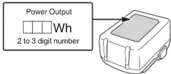
Notify the transporting company that a package contains a lithium-ion battery, inform the company of its power output and follow the instructions of the transportation company when arranging transport.
○ Lithium-ion batteries that exceed a power output of 100 Wh are considered to be in the freight classification of Dangerous Goods and will require special application procedures.
○ For transportation abroad, you must comply with international law and the rules and regulations of the destination country.
USB DEVICE CONNECTION PRECAUTIONS (UC18YSL3)
When an unexpected problem occurs, the data in a USB device connected to this product may be corrupted or lost. Always make sure to back up any data contained in the USB device prior to use with this product.
Please be aware that our company accepts absolutely no responsibility for any data stored in a USB device that is corrupted or lost, nor for any damage that may occur to a connected device.
WARNING
○ Prior to use, check the connecting USB cable for any defect or damage.
Using a defective or damaged USB cable can cause smoke emission or ignition.
When the product is not being used, cover the USB port with the rubber cover.
Buildup of dust etc. in the USB port can cause smoke emission or ignition.
NOTE
- There may be an occasional pause during USB recharging.
When a USB device is not being charged, remove the USB device from the charger.
Failure to do so may not only reduce the battery life of a USB device, but may also result in unexpected accidents.
○ It may not be possible to charge some USB devices, depending on the type of device.
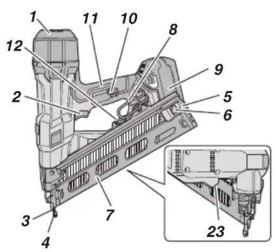
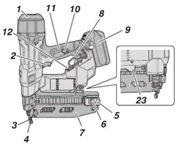
NAMES OF PARTS
The numbers in the list below correspond to Fig. 1–Fig. 25.
| 1 | Top cover |
| 2 | Trigger |
| 3 | Firing head (outlet) |
| 4 | Push lever |
| 5 | Nail feeder (B) |
| 6 | Nail feeder (A) |
| 7 | Magazine |
| 8 | Hook |
| 9 | Battery |
| 10 | Switch lock lever |
| 11 | Handle |
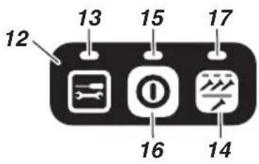
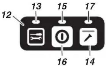
| 12 | Operation panel |
| 13 | Information indicator |
| 14 | Nailing operation switch(New Zealand model of NT1865DSA specifications excluded) |
| 15 | Power indicator |
| 16 | Power switch |
| 17 | Nailing operation indicator |
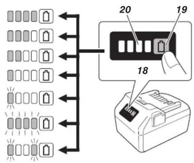
| 18 | Display panel |
| 19 | Battery level indicator switch |
| 20 | Battery level indicator lamp |
| 21 | Charge indicator lamp |
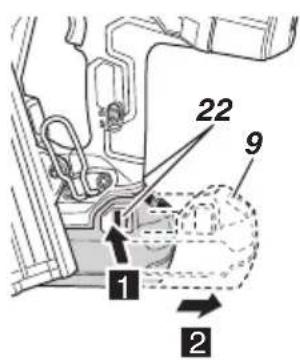
| 22 | Latch |
| 23 | LED light |
| 24 | Adjuster |
| 25 | Hook plate |
| 26 | Hex. bar wrench |
| 27 | Nose cap |
| 28 | Lock lever |
| 29 | Guide plate |
| 30 | Driver blade |
SYMBOLS
WARNING
The following show symbols used for the machine. Be sure that you understand their meaning before use.
 | NT1865DAA / NT1865DSA: Cordless Finish Nailer |
 | To reduce the risk of injury, user must read instruction manual. |
| Direct current | |
 | Switching ON |
 | Switching OFF |
 | Disconnect the battery |
 | Power switch |
 | Nailing operation switch(New Zealand model of NT1865DSA specifications excluded) |
 | Trigger locked |
 | Trigger unlocked |
 | Shallow side |
 | Deep side |
 | Do not use on scaffoldings, ladders. |
 | Warning |
 | Prohibited action |
Battery
 | Lights;The battery remaining power is over 75%. |
 | Lights;The battery remaining power is 50%-75%. |
 | Lights;The battery remaining power is 25%-50%. |
 | Lights;The battery remaining power is less than 25%. |
 | Blinks;The battery remaining power is nearly empty.Recharge the battery soonest possible. |
 | Blinks;Output suspended due to high temperature.Remove the battery from the tool and allow it to fully cool down. |
 | Blinks;Output suspended due to failure or malfunction.The problem may be the battery so please contact your dealer. |
SPECIFICATIONS
- Cordless Finish Nailer
| Model | NT1865DAA NT1 | 1865DSA |
| Motor DC Brushless | ||
| Applicable Nail 15 | Ga (Angle: 34°) 16 Ga | |
| Applicable Nail Length | 32 mm to 64 mm 25 | mm to 64 mm |
| Nail Loading capacity | 100 nails(1 strip) | 100 nails(2 strips) |
| Cycle rate 3.0 nails/second (Intermittent) | ||
| Weight*1 | 3.5 kg(BSL36A18X) | 3.4 kg(BSL36A18X) |
| Dimension*1HeightLengthWidth | 354 mm298 mm140 mm | 342 mm295 mm104 mm |
| Firing mode Full sequential / Contact (Selectable)* 2 | ||
*1 Excluding hook portion
*2 Only full sequential mode is available for New Zealand model of NT1865DSA specifications
NOTE
Due to HiKOKI's continuing program of research and development, the specifications herein are subject to change without prior notice.
- Battery
| Model Voltage Battery capacity | ||
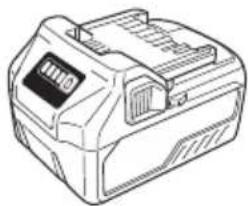
| BSL36A18X 36 / 1 | 8 V*1 | 2.5 / 5.0 Ah*1 |
*1 The tool itself will automatically switch over.
NAIL SELECTION
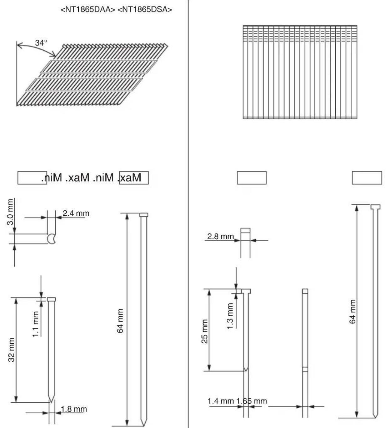
Choose a suitable nail from Fig. 2. Nails which are not shown in Fig. 2 can not be driven with this tool.
The use of any other nails can result in tool malfunction and/or nail breakdown, leading to serious injuries. [NT1865DAA]
15 Gauge finish nails (Angle: 34°) [NT1865DSA]
16 Gauge finish nails (straight)
STANDARD ACCESSORIES
In addition to the main unit (1 unit), the package contains the accessories listed on page 21.
Standard accessories are subject to change without notice.
APPLICATIONS
○ Nailing as finishing process for areas around the doors, windows as well as edgings.
○ Securing the bottom of drawers. Making various cases and cabinets.
CHARGING
Before using the power tool, charge the battery as follows.
-
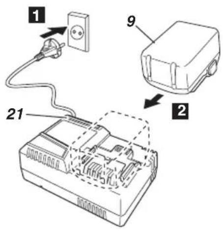
Connect the charger's power cord to the receptacle.
When connecting the plug of the charger to a receptacle, the charge indicator lamp will blink in red. (See Table 1) -
Insert the battery into the charger.
Firmly insert the battery into the charger as shown in Fig. 4 (on page 4).
- Charging
When inserting a battery in the charger, charging will commence and the charge indicator lamp will blink in blue.
When the battery becomes fully recharged, the charge indicator lamp will light up in green. (See Table 1)
(1) Charge indicator lamp indication
The indications of the charge indicator lamp will be as shown in Table 1, according to the condition of the charger or the rechargeable battery.
Table 1: Indications of the charge indicator lamp
| ON/OFF at 0.5 sec. intervals (RED) | Before charging *1 |
| Lights for 0.5 sec. at intervals of 1 sec. (BLUE) | Charged at less than 50% |
| Lights for 1 sec. at intervals of 0.5 sec. (BLUE) | Charged at less than 80% |
| Lights continuously (BLUE) | Charged at more than 80% |
| Lights continuously (Continuous buzzer sound: about 6 sec.) (GREEN) | Charging complete |
| ON/OFF at 0.3 sec. intervals (RED) | Overheat standby *2 |
| ON/OFF at 0.1 sec. intervals (Intermittent buzzer sound: about 2 sec.) (PURPLE) | Charging impossible *3 |
NOTE
*1 If the red lamp continues to blink even after the charger has been attached, check to confirm that the battery has been fully inserted.
*2 Battery overheated. Unable to charge. Although charging will start once the battery has cooled down even when left in situ, the best practice is to remove the battery and allow it to cool down in a shaded, well-ventilated location before charging.
*3 Malfunction in the battery or the charger
– Fully insert the battery.
- Check to confirm that no foreign matter is stuck to the battery mount or terminals. If there are no foreign objects, it is probable that the battery or charger is malfunctioning. Take it to your authorized Service Center.
When the battery charger has been continuously used, the battery charger will be heated, thus constituting the cause of the failures. Once the charging has been completed, give 5 minutes rest until the next charging.
(2) Regarding the temperatures and charging time of the battery (See Table 2)
Table 2
| Model UC18YSL3 | ||
| Type of battery Li-ion | ||
| Charging voltage 14.4–18 V | ||
| Temperatures at which the battery can be recharged | 0°C–50°C | |
| Charging time for battery capacity, approx. (At 20°C) | 1.5 Ah 15 min | |
| 2.0 Ah 20 min | ||
| 2.5 Ah 25 min | ||
| 3.0 Ah | 20 min(BSL1430C, BSL1830C: 30 min) | |
| 4.0 Ah | 26 min(BSL1840M: 40 min) | |
| Charging time for battery capacity, approx. (At 20°C) | 5.0 Ah 32 | min |
| 6.0 Ah 38 | min | |
| Charging time for multi volt battery capacity, approx. (At 20°C) | 1.5 Ah (×2 unit) | 20 min |
| 2.5 Ah (×2 unit) | 32 min | |
| 4.0 Ah (×2 unit) | 52 min | |
| Number of battery cells 4–10 | ||
| Charging voltage for USB 5 V | ||
| Charging current for USB 2 A | ||
| Weight 0.6 kg | ||
NOTE
- The recharging time may vary according to the ambient temperature and power source voltage.
○ If charging takes a long time
- Charging will take longer at extremely low ambient temperatures. Charge the battery in a warm location (such as indoors).
- Do not block the air vent. Otherwise the interior will overheat, reducing the charger's performance.
-
If the cooling fan is not operating, contact a HiKOKI Authorized Service Center for repairs.
-
Disconnect the charger's power cord from the receptacle.
-
Hold the charger firmly and pull out the battery. NOTE
Be sure to pull out the battery from the charger after use, and then keep it.
Regarding electric discharge in case of new batteries, etc.
As the internal chemical substance of new batteries and batteries that have not been used for an extended period is not activated, the electric discharge might be low when using them the first and second time. This is a temporary phenomenon, and normal time required for recharging will be restored by recharging the batteries 2–3 times.
How to make the batteries perform longer.
(1) Recharge the batteries before they become completely exhausted. When you feel that the power of the tool becomes weaker, stop using the tool and recharge its battery. If you continue to use the tool and exhaust the electric current, the battery may be damaged and its life will become shorter.
(2) Avoid recharging at high temperatures. A rechargeable battery will be hot immediately after use. If such a battery is recharged immediately after use, its internal chemical substance will deteriorate, and the battery life will be shortened. Leave the battery and recharge it after it has cooled for a while.
BEFORE USE
| Action Figure Page | ||
| Remaining battery indicator 3 4 | ||
| Removing and inserting the battery | 5 4 | |
| Charging a USB device from an electrical outlet | 24-a 7 | |
| Charging a USB device and battery from an electrical outlet | 24-b 7 | |
| How to recharge USB device 25 7 | ||
| Selecting accessories — 22 |
1. How to operate operation panel
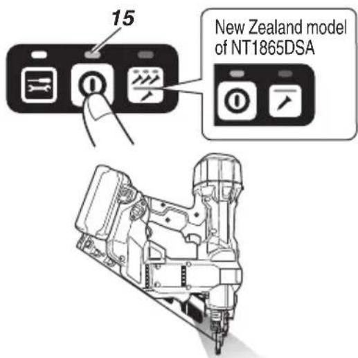
(1) Power switch ON (See Fig. 6)
Under the condition of "Power switch OFF", push and hold on Power switch more than 1 second, then power indicator lights in Green.
NOTE
Do not press the push lever and/or pull the trigger during the process of turning the power switch ON.
Doing so will prevent the power switch from turning ON.
[Auto power off]
When the power is turned on but the Nailer is not used for 30 minutes, the Nailer is automatically turned off. To turn on again, press the power switch.
WARNING
Never leave the Nailer with the power on. This could result in an accident.
(2) Power switch OFF (See Fig. 6)
Under the condition of "Power switch ON", push and hold on Power switch more than 1 second, then power indicator goes off. Under the condition of "Power switch ON", functions below are active.
(3) How to use the LED light (See Fig. 7)
While the power switch on, the LED light will automatically light up the tip portion of the tool.
CAUTION
○ Do not expose directly your eye to the light by looking into the light. If your eye is continuously exposed to the light, your eye will be hurt.
○ Wipe off any dirt or grime attached to the lens of the LED light with a soft cloth, being careful not to scratch the lens. Scratches on the lens of the LED light can result in decreased brightness.
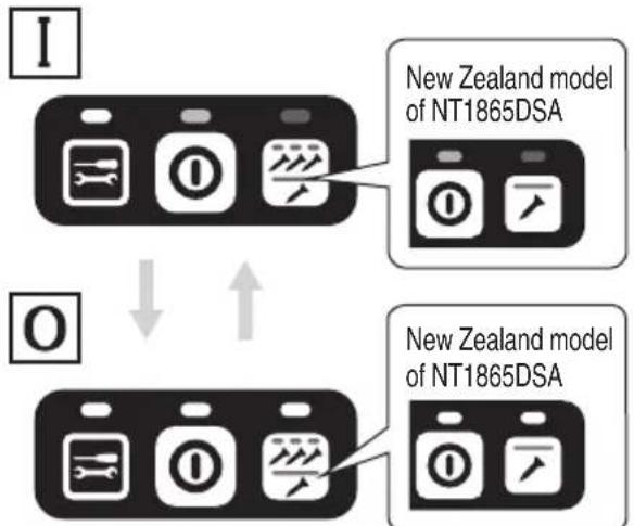
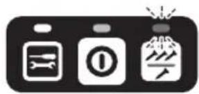
(4) Select Nailing operation mode (Full sequential actuation / Contact actuation) After power switch turn ON, always set in Full sequential actuation mode as initial. (Nailing operation indicator light in blue.) (See Fig. 8) To change nailing operation mode, push Nailing operation switch once. Every pushing, mode will change between “Full sequential” and “Contact”. Lighting (Blue): FULL SEQUENTIAL ACTUATION MECHANISM, Blinking (Blue): CONTACT ACTUATION MECHANISM
NOTE
New Zealand model of NT1865DSA specifications are only equipped for full sequential actuation mechanism mode and the nailing operation mode cannot be switched. These New Zealand models are not equipped with a nailing operation switch.
(5) Other functions In case of operation error, LED lamps show as below. (Fig. 1, 7)
| Status of indicator | |
| Information indicator blinks in red.The power automatically turns off after 60 seconds. | The battery remaining power is nearly empty.Recharge the battery as soon as possible. |
| Information indicator blinks in red and LED light blinks in 0.5 second interval.The power automatically turns off after 10 seconds. | Machine is in too cold (below -5°C) or too hot condition.Allow the nailer to cool or warm-up thoroughly in adequate condition. |
| Information indicator blinks in orange.The power automatically turns off within 10 seconds. | Contact HiKOKI for inspection. |
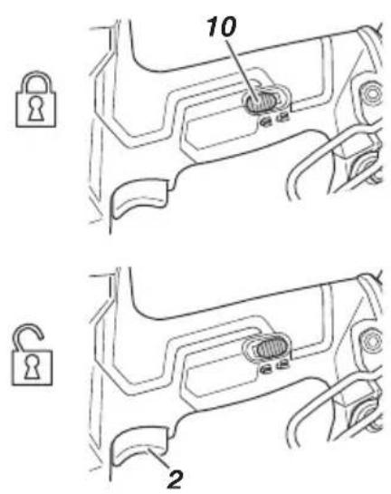
2. Trigger Lock Mechanism (See Fig. 9)
WARNING
○ Make sure the trigger is locked when not firing nails.
- This Nailer has a lock mechanism to prevent the nails from being fired.
○ Set the switch lock lever at the position to lock the trigger.
- Slide the switch lock lever to the position when the Nailer is to be used, and to the position when it is not in use.
3. Testing the nailer
WARNING
O Make sure the trigger is locked when not firing nails. (See Fig. 9)
O Never use Nailer unless push lever is operating properly.
○ The machine employs a preventive mechanism for unloaded operation.
When there are 10 or fewer nails remaining, the Empty-Firing Prevention Function activates, and nails are no longer driven when the trigger is pulled. If this happens, load more nails to continue driving them.
CAUTION
Use caution not to throw the push lever tip onto wood. Before actually beginning the nailing work, test the Nailer by using the checklist below. Conduct the tests in the following order.
If abnormal operation occurs, stop using the Nailer and contact a HiKOKI authorized service center immediately.
(1) REMOVE ALL NAILS AND BATTERY FROM NAILER.
- ALL SCREWS MUST BE TIGHTENED.
- THE PUSH LEVER AND TRIGGER MUST MOVE SMOOTHLY.
(2) Installing the battery. Do not operate the push lever or trigger while installing the battery. (See Fig. 5)
(3) Turn on the Power switch. (See Fig. 6) Turn on the Power switch by push and hold on Power switch more than 1 second. Make sure the power indicator is lighting in green, and nailing operation indicator is lighting in blue. (FULL SEQUENTIAL ACTUATION MECHANISM)
(4) Remove the finger from the trigger and press the push lever against the workpiece with pulling back the nail feeder (B).
(5) Separate the push lever from the workpiece. Next, point the nailer downward, with pulling back the nail feeder (B), pull the trigger and then wait in that position for 5 seconds or longer.
[1] Without touching the trigger, depress the push lever against the workpiece with pulling back the nail feeder (B).
Next, pull the trigger.
[2] Hold the trigger back and depress the push lever against the workpiece again.
[3] Separate the finger from the trigger. Next, [1] is operated again.
(7) Separate the push lever from the workpiece, pull the trigger.
Depress the push lever against the workpiece within 2 seconds.
(8) (New Zealand model of NT1865DSA specifications excluded)
Set the nailing operation indicator blinking ON mode. (CONTACT ACTUATION MECHANISM)
Push the nailing operation switch once, make sure that the indicator is blinking Blue.
Separate the push lever from the workpiece, pull the trigger.
Depress the push lever against the workpiece within 2 seconds.
(9) If no abnormal operation is observed, you may load nails in the Nailer.
Drive nails into the workpiece that is the same type to be used in the actual application.
4. Checking push lever operations WARNING
Make sure the trigger is locked when not firing nails. Always make sure the trigger is locked and the battery removed from the power tool when checking push lever operations.
Check to make sure the push lever slides smoothly when operated.
Clean the sliding area on the push lever if it doesn't slide smoothly.
5. Loading nails WARNING
When loading nails into Nailer,
1) remove battery from the nailer;
2) do not pull trigger;
3) do not depress push lever; and
4) keep nailer pointed downward.
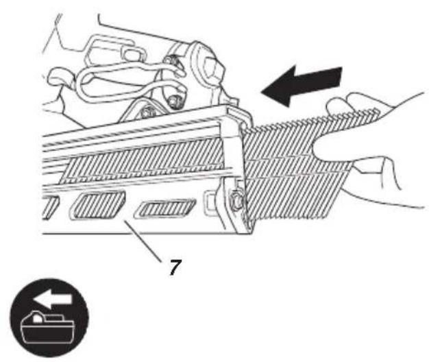
(1) Insert nail strip into the back of the magazine. (See Fig. 10)
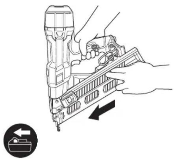
(2) Slide the nail strip forward in the magazine. (See Fig. 11)
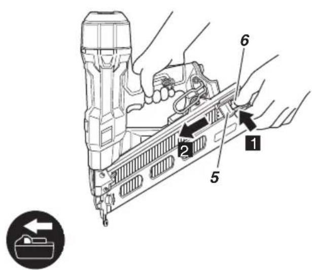
(3) Push the nail feeder (A) to engage the nail feeder (B) to the nail strip. (See Fig. 12)
NOTE
- Quietly push the nail feeder (A) and nail feeder (B) against the nail. If the nail feeder (A) and nail feeder (B) are released from backward the magazine and bumped against the nail, the connecting adhesive of the nail can be damaged.
○ Use nail strip of more than 10 nails.
○ Use an unbroken nail strip with nails of all the same length.
The Nailer is now ready to operate.
Removing the nails:
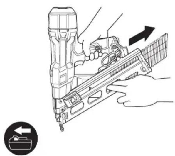
(1) Press the knob of nail feeder (A) to release the lock of the nails, then gently return nail feeder (B) forward. (Fig. 13)
(2) Pull out nails from the back of the magazine. (See Fig. 14)
NOTE
There may be a nail remaining in the blade guide. It is difficult to see if there is a nail remaining in the blade guide, so check to ensure there is not.
○ NEVER point tool at yourself or others in work area.
- Keep fingers AWAY from trigger when not driving nails to avoid accidental firing.
○ Do not use the electrical cord if damaged. Have it repaired immediately.
○ Choice of triggering method is important. Please read and understand "1. Nailing procedures" found below.
Before starting work, check the nailing operation switching device.
This HiKOKI nailer includes a nailing operation switching device.
Before starting work, make sure that the switching device is properly set.
If the switching device is not set properly, the nailer will not operate correctly.
○ Never place your face, hands or feet near firing head when using.
○ Do not drive nails on top of other nails or with Nailer at too steep of an angle; nails can ricochet and hurt someone.
○ Do not drive nails into thin boards or near corners and edges of workpiece. Nails can be driven through or away from workpiece and hit someone.
Never drive nails from both sides of a wall at the same time. Nails can be driven into and through the wall and hit a person on the opposite side.
O Never use Nailer which is defective or operating abnormally.
○ Do not use Nailer as hammer.
O Remove all remaining fasteners and battery from nailer when:
1) doing maintenance and inspection;
2) checking proper operation of push lever and trigger;
3) attaching or removing the nose cap;
4) cleaning a jam;
5) it is not in use;
6) leaving work area;
7) moving it to another location; and
8) handing it to another person.
○ Remove battery from Nailer when:
1) loading nails;
2) turning the adjuster.
This HiKOKI nailer is equipped with a nailer operation switching device.
Use FULL SEQUENTIAL ACTUATION MECHANISM or CONTACT ACTUATION MECHANISM in accordance with the work to be performed.
NOTE
New Zealand model of NT1865DSA specifications are only equipped for the FULL SEQUENTIAL ACTUATION MECHANISM.
Explanation of the various nailing operations
O FULL SEQUENTIAL ACTUATION MECHANISM:
First, press the push lever against the wood; next, pull the trigger to drive the nail.
Follow the same sequence to continue driving nails.
After nailing once, nailing will not be possible again until remove finger from the trigger and lift the tool off the wood surface completely.
O CONTACT ACTUATION MECHANISM:
CONTACT ACTUATION can follow two different sequences, depending on your use.
To drive several nails:
1) Pull the trigger.
2) Press the push lever against the wood to drive the nail.
3) If the trigger is held back, a nail will be driven each time the push lever is pressed against the wood.
To drive a single nail:
1) Press the push lever against the wood.
2) Pull the trigger to drive the nail.
3) Remove your finger from the trigger and remove the nailer from the wood.
[Dry-fire lockout mechanism]
When there are 10 or fewer nails remaining, the Empty-Firing Prevention Function activates, and nails are no longer driven when the trigger is pulled. If this happens, load more nails to continue driving them.
CAUTION
Use caution not to throw the push lever tip onto wood when the push lever cannot be pushed up.
1. Nailing procedures
This Nailer is equipped with the push lever and does not operate unless the push lever is depressed.
There are two methods of operation to drive nails with this Nailer.
They are:
1) Intermittent operation (Trigger fire):
2) Continuous operation (Push lever fire):
NOTE
New Zealand model of NT1865DSA specifications are only equipped for the intermittent operation (trigger fire) method. The New Zealand model cannot be switched to the continuous operation (push lever fire) method.
(1) Intermittent operation (Trigger fire)
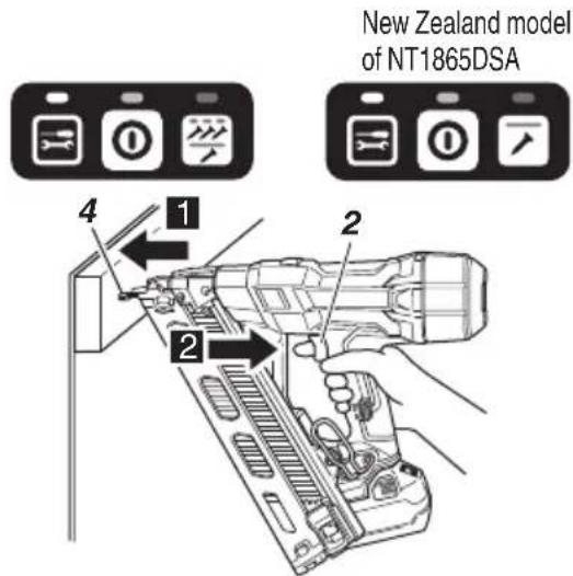
Use the FULL SEQUENTIAL ACTUATION MECHANISM setting. (See Fig. 15)
WARNING
To avoid double firing or accidental firing due to recoil. – Pull the trigger rapidly and firmly.
[1] Set the nailing operation switch to FULL SEQUENTIAL ACTUATION MECHANISM (Nailing operation indicator is light in blue.)
[2] Position the nail outlet on the workpiece with finger off the trigger.
[3] Depress the push lever firmly until it is completely depressed.
[4] Pull the trigger to drive a nail.
[5] Remove finger from the trigger and lift the tool off the wood surface completely.
To continue nailing in a separate location, move the nailer along the wood, repeating steps [2]–[5] as required.
NOTE
Operations [3] and [4] should be done within 2 seconds of each other. If more than 2 seconds pass after [3], the Nailer will not work properly. If this happens, retry from [3].
(2) Continuous operation (Push lever fire)
Using CONTACT ACTUATION MECHANISM (See Fig. 16)
WARNING
To avoid double firing or accidental firing due to recoil.
- Do not press the nailer against the wood with excessive force.
- Separate the nailer from the wood as it recoils after nailing.
[1] Set the nailing operation switch to CONTACT ACTUATION MECHANISM (Nailing operation indicator is blink in blue.)
[2] Pull the trigger with the Nailer off the workpiece.
[3] Depress the push lever against the workpiece to drive a nail.
[4] Move the Nailer along the workpiece with a bouncing motion.
Each depression of the push lever will drive a nail.
As soon as the desired number of nails have been driven, remove finger from the trigger.
NOTE
Operations [2] and [3] should be done within 2 seconds of each other. If more than 2 seconds pass after [2], the Nailer will not work properly. If this happens, retry from [2].
WARNING
Keep your finger off the trigger except during nailing operation, because serious injury could result if the push lever accidentally contacts you or others in work area.
Keep hands and body away from the discharge area. This HiKOKI nailer may bounce from the recoil of driving a nail and unwanted subsequent nail may be driven, possibly causing injury.
NOTE
○ If all warnings and instructions are followed, safe operation is possible with all two systems: FULL SEQUENTIAL ACTUATION MECHANISM, CONTACT ACTUATION MECHANISM.
○ Always handle nails and package carefully. If nails are dropped, collating bond may be broken, which will cause mis-feeding and jamming.
○ After nailing:
1) remove battery from the Nailer;
2) remove all nails from the Nailer;
2. Adjusting the nailing depth
To assure that each nail penetrates to the same depth, be sure that the Nailer is always held firmly against the workpiece.
If nails are driven too deep or shallow into the workpiece, adjust the nailing in the following order.
(1) Remove the battery from the Nailer. (See Fig. 5)
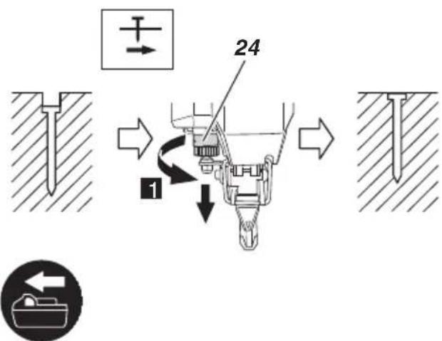
(2) If nails are driven too deep, turn the adjuster to the shallow side. (See Fig. 17)
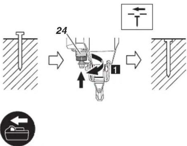
Adjustments are in half-turn increments. If nails are driven too shallow, turn the adjuster to the deep side. (See Fig. 18)
(3) Stop turning the adjuster when a suitable position is reached for a nailing test.
(4) Connect the battery to the Nailer.
WARNING
Safety glasses should not be inferior to the specification set in AS/NZS 1337 Eye protectors for industrial applications.
Perform a nailing test.
3. Using the hook (See Fig. 19)
WARNING
When using the hook, turn off the power switch (green light "OFF"). Pay sufficient attention so that the main equipment does not fall. If the tool falls, there is a risk of accident.
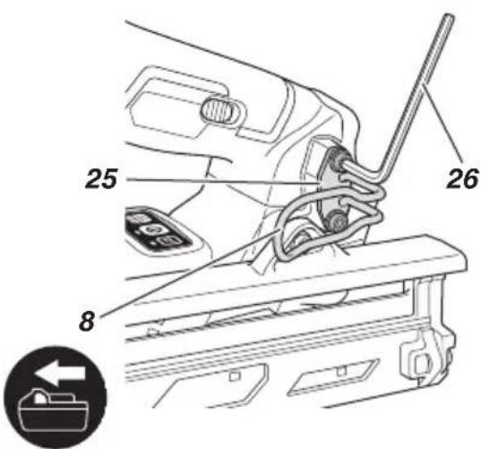
Hook can be installed on the left or right side.
(1) Remove the battery, then remove all remaining nails from the magazine.
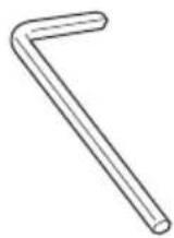
(2) Securely hold the main unit and remove the M5 bolts using the hex. bar wrench.
(3) Remove the hook and hook plate.
(4) Install the hook on the other side and securely fasten with M5 bolts.
NOTE
Hook can be used as a hanger.
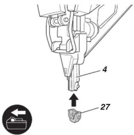
4. Using the nose cap (See Fig. 20)
WARNING
When attaching or detaching the nose cap, be sure to remove your finger from the trigger and remove all remaining fasteners and the battery from the nailer.
If you like to protect the surface of workpiece against scratches or markings made by the push lever, attach the accessory nose cap to the push lever.
(1) Remove all remaining fasteners and battery from nailer.
(2) Put the nose cap to the toe of the push lever.
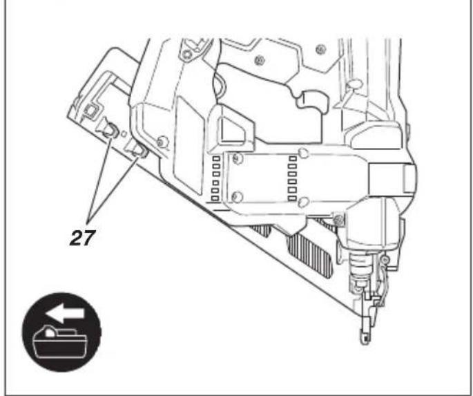
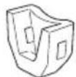
(3) There are extra nose caps in the storage spots on the underside of the magazine. (See Fig. 21)
NOTE
The nose cap may reduce nailing depth due to its thickness. Re-adjustment of nailing depth is required.
5. Clearing a jam
If nails are jammed in the firing head, remove them in the following order.
WARNING
Be sure to turn off the power switch and pull out the battery.
CAUTION
NEVER point the firing head at yourself or another person, to avoid risk of injury by mis-firing. Even if the battery is removed from the nailer, there is still energy of compressed air remaining inside.
(1) Remove the battery from the Nailer.
(2) Remove all nails from the magazine.
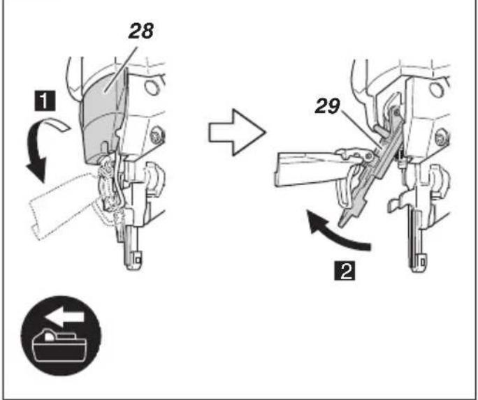
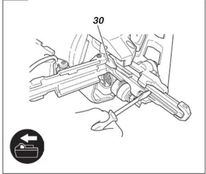
(3) Release the Lock lever and open guide plate. (See Fig. 22)
(4) Remove the jammed nail with a slotted-head screwdriver. (See Fig. 23)
CAUTION
NEVER hit the driver blade.
(5) Close guide plate and latch.
(6) After assembling, ensure that the push lever slides smoothly.
NOTE
If the tip of the driver blade becomes worn, nail jamming is more likely to occur.
In case of frequent jam, contact a HiKOKI authorized service center.
MAINTENANCE AND INSPECTION
WARNING
Be sure to remove all remaining fasteners and battery from the nailer before maintenance and inspection.
1. Inspecting the magazine
(1) Remove battery from the Nailer.
(2) Clean the magazine. Remove dust and wooden chips which may have accumulated in the magazine.
CAUTION
○ Check that the nail feeder(A) and (B) move smoothly by pulling it with finger.
○ If not smooth, nails can be driven at an irregular angle and hurt someone.
2. Inspecting the mounting screws
Regularly inspect all mounting screws and ensure that they are properly tightened. Should any of the screws be loose, retighten them immediately. Failure to do so could result in serious hazard.
- Maintenance chart
| ACTION WHY | HOW | |
| Clean magazine and feeder mechanism. | Prevent a jam. Blow | clean daily. |
| Keep push lever working properly. | Promote operator safety and efficient Nailer operation. | Blow clean daily. |
4. Everyday maintenance
When cleaning the push lever, open the guide plate and use a blower or brush, etc. to remove dust from the sliding part of the push lever. (See Fig. 26) After finishing the cleaning and closing the guide plate, ensure that the push lever slides smoothly.
5. Maintenance of the motor
The motor unit winding is the very “heart” of the power tool. Exercise due care to ensure the winding does not become damaged and/or wet with oil or water.
6. Cleaning on the outside
When the power tool is stained, wipe with a soft dry cloth or a cloth moistened with soapy water. Do not use chloric solvents, gasoline or paint thinner, for they melt plastics.
7. Storage
Store the power tool in a place in which the temperature is less than 40^ C and out of reach of children.
NOTE
Storing lithium-ion batteries.
Make sure the lithium-ion batteries have been fully charged before storing them.
Prolonged storage (3 months or more) of batteries with a low charge may result in performance deterioration, significantly reducing battery usage time or rendering the batteries incapable of holding a charge.
However, significantly reduced battery usage time may be recovered by repeatedly charging and using the batteries two to five times.
If the battery usage time is extremely short despite repeated charging and use, consider the batteries dead and purchase new batteries.
CAUTION
In the operation and maintenance of power tools, the safety regulations and standards prescribed in each country must be observed.
Important notice on the batteries for the HiKOKI cordless power tools
Please always use one of our designated genuine batteries. We cannot guarantee the safety and performance of our cordless power tool when used with batteries other than these designated by us, or when the battery is disassembled and modified (such as disassembly and replacement of cells or other internal parts).
NOTE
Due to HiKOKI's continuing program of research and development, the specifications herein are subject to change without prior notice.
TROUBLESHOOTING
Use the inspections in the table below if the tool does not operate normally. If this does not remedy the problem, consult your dealer or the HiKOKI Authorized Service Center.
| PROBLEM CHECK METHOD CORRECTION | ||
| Power switch doesn't turn on. Turn on once, but turn off automatically. | Low battery charge. Charge the battery. | |
| Damaged internal electronics. Contact | HiKOKI for replacement. | |
| Push lever and/or trigger is ON state? | Keep push lever and trigger in OFF state. | |
| Keep no operation over 30 minutes? (Auto-power off function) | Push and hold power switch more than 1 second to switch “ON” | |
| Nailer doesn't operate (Power switch ON). | Nailer not enough pressed against workpiece. | Hold nailer firmly and press to the workpiece completely. |
| Trigger not enough pulled. Pull the trigger firmly. | ||
| More than 2 seconds pass from push lever ON to trigger ON (or trigger ON to push lever ON). (LED light blinks at 1-second intervals) | Make sure that less than 2 seconds pass between push lever ON and trigger ON (or between trigger ON and push lever ON). | |
| Preventive mechanism activated. (No nails, or too few fasteners remaining) (LED light blinks for 3 seconds at 1-second intervals) | Reload the nails into magazine. | |
| Switch lock lever (Trigger lock function) is “ON” position. | Set switch lock lever to “OFF” position. (Refer to “BEFORE USE” > “2. Trigger Lock Mechanism”) | |
| Machine is too cold (below -5°C) or too hot. (LED light blinks at 0.5-second intervals, and 10 seconds later the power turns OFF) | Allow the nailer to cool or warm-up throughly in adequate condition. | |
| Damaged internal electronics. Contact | HiKOKI for replacement. | |
| Nailer operates, but no nail is driven. | Magazine is dirty. Blow and wipe clean the magazine. | |
| Check for a jam. Clear a jam (refer to “HOW TO USE THE NAILER” > “5. Clearing a jam”). | ||
| Driver blade worn or damaged? Contact | HiKOKI for replacement. | |
| Ribbon spring weakened or damaged? | Replace ribbon spring. | |
| Nail feeder (A) damaged? Replace nail feeder (A). | ||
| Nail feeder (B) damaged? Replace nail feeder (B). | ||
| Check for proper nails. Use only recommended nails. | ||
| Weak drive. Slow to cycle. | Check position of nailing depth adjustment adjuster. | Readjust according to “HOW TO USE THE NAILER” > “2. Adjusting the nailing depth”. |
| Weak drive.Slow to cycle. | Driver blade worn? Contact HiKOKI for | replacement. |
| Compressed air pressure has become low. | ||
| Damaged internal electronics. | ||
| Drives too deep. Check position of nailing depth adjustment adjuster. | Readjust according to “HOW TO USE THE NAILER” >“2. Adjusting the nailing depth”. | |
| Skipping nails.Intermittent feed. | Check for proper nails. Use only recommended nails. | |
| Nail feeder (A) damaged? Replace nail feeder (A). | ||
| Nail feeder (B) damaged? Replace nail feeder (B). | ||
| Ribbon spring weakened or damaged? | Replace ribbon spring. | |
| Driver blade worn or damaged? Contact HiKOKI for replacement. | ||
| Nails jam.Driven nail is bent. | Check for proper nails. Use only recommended nails. | |
| Driver blade worn or damaged? Contact HiKOKI for replacement. | ||
| NT1865DAA NT1865DSA | ||||
| (2XCP) (NN) (2XCP) (NN) | ||||
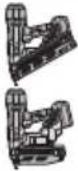
 | 1 1 1 1 | |||
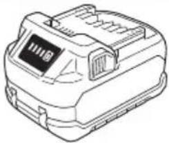 BSL36A18X BSL36A18X | 2-2- | |||
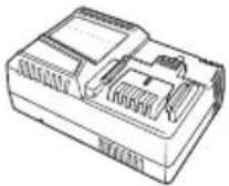 UC18YSL3 UC18YSL3 | 1-1- | |||
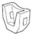 | 3 3 3 3 | |||
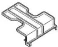 | 1-1- | |||
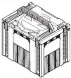 | 1-1- | |||
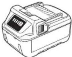
natural_image
Line drawing of a handheld electronic device with display and control panel (no text or symbols)BSL18.. BSL36..18
natural_image
Line drawing of a battery pack with control panel and display (no text or symbols)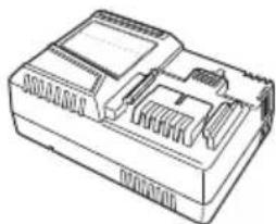
natural_image
Line drawing of a mechanical component with internal slots and housing (no text or symbols)UC18YSL3 (14.4 V–18 V) 875769
329897 382165
natural_image
Isometric line drawing of a mechanical housing or enclosure with internal components (no text or symbols)337528 944458
natural_image
Line drawing of a quill pen in an inkwell (no text or symbols)Koki Holdings Co., Ltd.
Shinagawa Intercity Tower A, 15-1, Konan 2-chome, Minato-ku, Tokyo, Japan
- NT 1865DAA • NT 1865DSA
- GENERAL POWER TOOL SAFETY WARNINGS
- WARNING
- Save all warnings and instructions for future reference.
- 1) Work area safety
- 2) Electrical safety
- 3) Personal safety
- 4) Power tool use and care
- 5) Battery tool use and care
- PRECAUTION
- ADDITIONAL SAFETY WARNINGS
- CAUTION ON LITHIUM-ION BATTERY
- CAUTION
- REGARDING LITHIUM-ION BATTERY TRANSPORTATION
- USB DEVICE CONNECTION PRECAUTIONS (UC18YSL3)
- NOTE
- NAMES OF PARTS
- SYMBOLS
- SPECIFICATIONS
- NAIL SELECTION
- STANDARD ACCESSORIES
- APPLICATIONS
- CHARGING
- Regarding electric discharge in case of new batteries, etc.
- How to make the batteries perform longer.
- How to operate operation panel
- Power switch ON (See Fig. 6)
- [Auto power off]
- Power switch OFF (See Fig. 6)
- How to use the LED light (See Fig. 7)
- Trigger Lock Mechanism (See Fig. 9)
- Testing the nailer
- Checking push lever operations WARNING
- Loading nails WARNING
- Nailing procedures
- Adjusting the nailing depth
- Using the hook (See Fig. 19)
- Using the nose cap (See Fig. 20)
- Clearing a jam
- MAINTENANCE AND INSPECTION
- Inspecting the magazine
- Inspecting the mounting screws
- Everyday maintenance
- Maintenance of the motor
- Cleaning on the outside
- Storage
- Important notice on the batteries for the HiKOKI cordless power tools
- TROUBLESHOOTING
- Koki Holdings Co., Ltd.
Brand : HiKOKI
Model : NT1865DSA
Category : Stapler