
Meridian 9.3 - Uncategorized FLIR - Free user manual and instructions
Find the device manual for free Meridian 9.3 FLIR in PDF.


| Brand | FLIR (Teledyne FLIR) |
| Model | Meridian 9.3 |
| Product Type | Network Video Recorder (NVR) System |
| Software Version | 9.2.1 (as of manual) |
| Supported Cameras | IP cameras, analog cameras via encoder, PTZ cameras |
| Recording Modes | Continuous, Motion, Custom Schedule |
| Max Storage | Depends on hardware; configurable in Storage Setup (up to 365 days lifespan) |
| Video Output | HDMI/VGA (via hardware platform); Web Client accessible from browser |
| Network Interfaces | At least one NIC for camera network; WAN connection optional |
| Power Supply | AC power adapter (included with hardware) |
| Dimensions | Standard 1U rackmount (approx. 17.2 x 1.7 x 10.5 inches) |
| Weight | Approx. 10 lbs (4.5 kg) |
| Operating Temperature | 0°C to 40°C (32°F to 104°F) |
| Security Features | TLS encryption, password policy, edge device certificate management |
| Analytics | Basic analytics (motion detection, intrusion zones, tripwires, masking) |
| User Management | Up to 3 default groups (Administrators, Supervisors, Operators); custom groups |
| Alarms & Rules | Event-triggered actions; email notifications; external device control |
| Maintenance | Database backup, log export, scheduled backups |
| Compatible Browsers | Chrome 29+, IE 11+, Opera 16+ |
| Mobile App | Supported (Horizon/Meridian mobile viewing application) |
Frequently Asked Questions - Meridian 9.3 FLIR
User questions about Meridian 9.3 FLIR
0 question about this device. Answer the ones you know or ask your own.
Ask a new question about this device
Download the instructions for your Uncategorized in PDF format for free! Find your manual Meridian 9.3 - FLIR and take your electronic device back in hand. On this page are published all the documents necessary for the use of your device. Meridian 9.3 by FLIR.
USER MANUAL Meridian 9.3 FLIR
Admin Center Help File
Horizon/Meridian
*
© 2022 TELEDYNE FLIR Systems, Inc. All rights reserved worldwide. No parts of this document, in whole or in part, may be copied, photocopied, translated, or transmitted to any electronic medium or machine readable form without the prior written permission of FLIR Systems, Inc.
Names and marks appearing on the products herein are either registered trademarks or trademarks of FLIR Systems, Inc. and/or its subsidiaries. All other trademarks, trade names, or company names referenced herein are used for identification only and are the property of their respective owners.
This product is protected by patents, design patents, patents pending, or design patents pending.
Photographs and images appearing in this document may have been modified for illustrative purposes using commercial image editing software and may not always reflect an actual product configuration.
For additional information visit www.teledyneflire.com.
The contents of this document are subject to change.
Teledyne FLIR LLC
6769 Hollister Avenue
Goleta, CA 93117
USA
Support: https://support.flir.com
Document History
| Version | Date | Comment |
| 1 | November 28, 2022 | Initial FLIR release |
Table of Contents
-
Horizon/Meridian Video Management System .... 1
-
Login Screen 3
2.1 SSA Expiry Notification 3
- Home Screen 4
3.1 Recommended Settings 5
3.2 Advanced Settings 6
3.3 Applications 6
3.4 Special Start-up Screens 7
3.4.1 Summary Screen - First time system is run .... 7 Automatic Update .... 73.4.2
- General Screen Layout 9
4.1 Sidebar 9
4.2 Item List 11
4.3 Settings Page 12
4.4 Action Buttons and Help 12
- System Screens 14
5.1 Dashboard 14
5.2 Server Settings 16
5.3 Licensing 18
5.4 Storage Setup 19
5.5 Site Setup 21
5.6 Maps 22
5.7 Logical IDs 26
5.8 Maintenance 27
5.9 IT Setup 28
5.10 Reports 30
- Cameras Screens 33
6.1 Edge Devices 34
6.1.1 Input Pins 37
6.1.2 Output Pins 38
6.1.3 Audio 39
6.1.4 Serial Ports 40
6.1.5 Adding New Devices 41
6.2 Camera Settings 41
6.2.1 Recording Schedule 44
Table of Contents
Copy Configuration 456.2.2
List of possible Camera States 466.2.3
6.3 Camera Sequence 47
6.4 Camera List 50
Camera - Detailed Settings Tabs for different Camera Capabilities 516.4.1
6.4.1.1 Video Settings 52
6.4.1.2 Picture Settings 54
6.4.1.3 Thermal Settings 55
6.4.1.4 PTZ Settings 57
6.4.1.5 Motion Detection Settings 60
6.4.1.6 Analytics Settings 61
- Users Screens 68
7.1 Users 69
7.2 User Groups 70
- Rules and Alarms Screens 73
8.1 Alarms 73
8.2 Rules 76
- Security Screens 80
9.1 Edge Devices (Security) 80
9.2 Password Policy (Security) 82
9.3 Settings (Security) 83
- About this File 89
1 Horizon/Meridian Video Management System
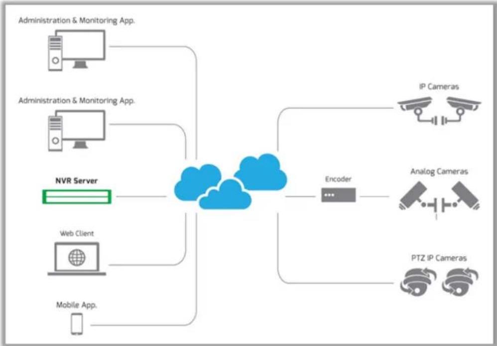
flowchart
graph TD
    A["Administration & Monitoring App."] --> C["Cloud"]
    B["Administration & Monitoring App."] --> C
    D["NVR Server"] --> C
    E["Web Client"] --> C
    F["Mobile App."] --> C
    C --> G["Encoder"]
    G --> H["IP Cameras"]
    G --> I["Analog Cameras"]
    G --> J["PTZ IP Cameras"]
Horizon/Meridian is a powerful, easy-to-set-up and easy-to-use NVR (Network Video Recorder) system that lets you control multiple IP video cameras, record content continuously by time schedule or when triggered by motion detection, set up multiple user accounts with configurable privileges, and define rules and alarms.
The Horizon/Meridian System is provided as a preloaded NVR System on Horizon and Meridian hardware platforms depending on the performance requirements of the user.
Admin Center - The Horizon/Meridian Admin Center application allows the user to initially set up the system, add cameras and other edge devices, set up schedules, rules and alarms, edit the configuration, and carry out routine maintenance.
Once set up, the user can easily view the system components and make changes where necessary.
Control Center - The Control Center application allows one or more Users to connect to the system, watch live and recorded video, and respond to alarms.
Web Client - A versatile Web Client allows any authorized user using a compatible browser to view live cameras and recordings, see alarms, and export clips from any PC on the user's corporate network
http:// [Horizon/Meridian URL]/webclient
Compatible Browsers
Chrome:
Version 29 and later
IE:
Version 11 and later
Opera:
Version 16 and later
Minimum resolution - 1280 x 800
2 Login Screen
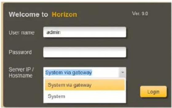
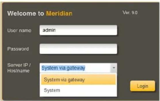
On startup of the Horizon/Meridian Admin Center, the User is shown a Login screen.
The user can enter a new Server IP/Hostname or choose from the drop-down list of previously-connected systems
2.1 SSA Expiry Notification
Users are notified their SSA is due to expire 60 days prior to expiration date.
This message appears when the user:
- Logs in
- If already logged in and the SSA expires or is about to expire
- If already logged in and the delayed reminder is due (after choosing the remind me later option)
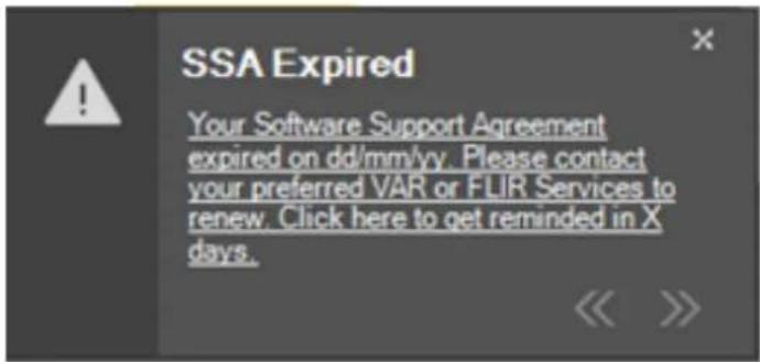
SSA Expiry Notification
The message only appears for users who have the permission to log into Admin Center.
3 Home Screen
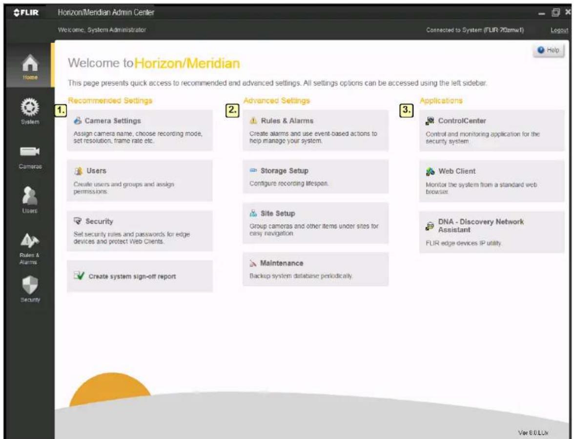
When a User logs in to Horizon/Meridian, the Home screen displays. *see Notes below
The Home screen shows the standard Sidebar on the left of the screen, and is divided into the following sections:
- Recommended Settings
- Advanced Settings
- Applications
The user can return to the Home screen from other system screens at any time, by clicking on the Home button in the Sidebar.
Notes:
In the following cases, the Home Screen is not the first screen shown:
- The first time the Horizon/Meridian Admin Center is run, a one-time Summary Screen displays.
- When running the Horizon/Meridian Admin Center on a client machine, if the Server and Client machines are running different versions of the application, an Automatic Update window displays.
'Check for Updates' link:
When running Horizon/Meridian Admin Center on a Client machine, then if Automatic Updates are enabled, the user can click on the 'Check for Updates' link at the bottom of the screen to check if a minor version update is available.
3.1 Recommended Settings
Recommended Settings

Camera Settings
Assign camera name, choose recording mode, set resolution, frame rate etc.

Users
Create users and groups and assign permissions.

Security
Set security rules and passwords for edge devices and protect Web Clients.

Create system sign-off report
The Recommended Settings are a series of links that guide the user through the tasks that should be performed after the software is installed and the Initial Setup Wizard has been run.
3.2 Advanced Settings
Advanced Settings

Rules & Alarms
Create alarms and use event-based actions to help manage your system.

Storage Setup
Configure recording lifespan.

Site Setup
Group cameras and other items under sites for easy navigation.

Maintenance
Backup system database periodically.
The Advanced Settings allow the user to apply local conditions:
- Set up Rules and Alarms, configure how much space is used for camera recordings, arrange according to 'Sites', and set up backup schedules.
3.3 Applications
Applications

Control Center
Control and monitoring application for the security system.

Web Client
Monitor the system from a standard web browser

DNA - Discovery Network Assista
FLIR edge devices IP utility.
From the Home screen of the Admin Center application, the user can:
- Launch the Control Center application,
• View the Control Center using a Web browser, or
- Launch the DNA Utility.
3.4 Special Start-up Screens
In the following cases, the Home Screen is not the first screen shown:
- The first time the Horizon/Meridian Admin Center is run, a one-time Summary Screen displays.
- When running the Horizon/Meridian Admin Center on a client machine, if the Server and Client machines are running different versions of the application, an Automatic Update window displays.
3.4.1 Summary Screen - First time system is run
![Welcome to Horizon/Meridian System is up and running! 6 Cameras are connected to the system. Camera are set at maximum resolution and at half their maximum frame rate. Cameras are set to record [Always] 803 [GB] of storage is already configured for video recordings. System is predefined with 3 default user groups, Administrators, Supervisors and Operators, each with its own set of predefined privileges. You may now use the Home Screen to continue setting up the system. OK](/content/2026/05/914014/images/59abaae6775bf9133243512ef903c425aa09106a1576502dd9356857745b4e44.jpg)
The Summary screen is shown after the Initial Startup Wizard has run, and the Horizon/Meridian system has been started up for the first time.
The screen shows that the Initial Setup Wizard has already:
• Discovered and set up cameras that it found on the Video Network
- Initialized storage and started recording using the parameters set in the Initial Startup Wizard
- Created a structure for Users allowing different sets of User permissions
Click OK to continue and proceed to the Home Screen, where the Recommended Steps show how to continue setting up the system.
3.4.2 Automatic Update
When running the Horizon/Meridian Admin Center on a client machine, an Automatic Update window is shown if the Horizon/Meridian Server has been updated and the client application is out of date. This provides the User the option to allow the application to be updated.
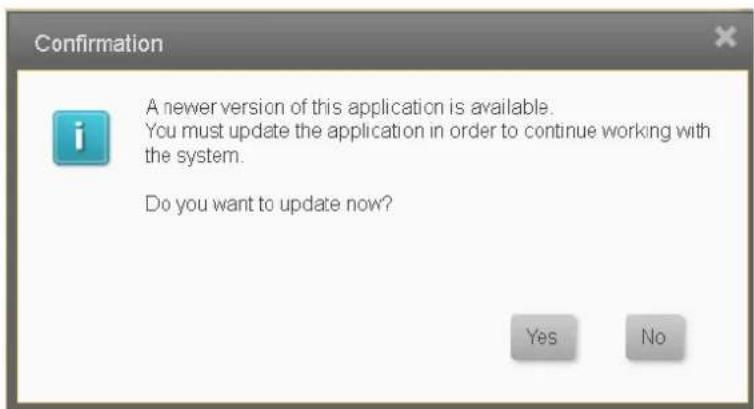
A progress bar is shown while the Update is taking place.
4 General Screen Layout
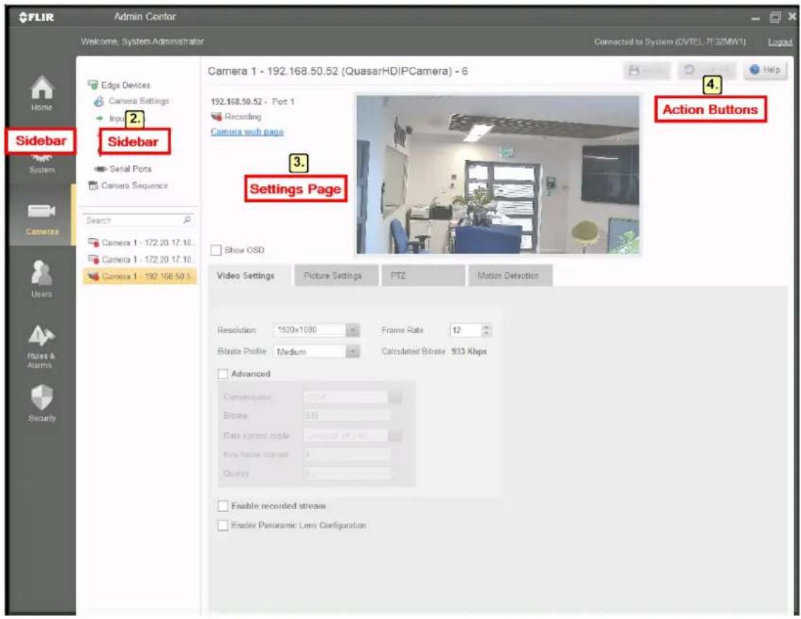
Horizon/Meridian Admin Center screens normally include the Sidebar, an Item List, a Settings Page, and a Help button.
4.1 Sidebar
The Sidebar is always on the left of the Horizon/Meridian screen. It lets you access any of the system screens.
The Home screen is opened when the Horizon/Meridian system is started up. Clicking the Home screen button when completing a task on any other screen returns the user to this screen.
The System button accesses the Server Settings, Licensing, Storage Setup, Site Setup, Maps, Maintenance, IT Setup, and Reports screens.
The Cameras button accesses the Edge Devices screens, which include the main Camera Settings screen, additional camera settings screens for Input Pins, Output Pins, Audio and Serial Ports. The button also accesses the Camera Sequence screen. In all these screens, there is a list of all cameras, and a Filter box which can be used to limit the displayed list to only show cameras who's names include the text entered in the Filter box.
The Users button accesses the Users and User Groups screens.
The Rules and Alarms button opens the Rules and Alarms screens.
The Security button opens the Edge Devices and Settings screens.
4.2 Item List
For any selected category in the Sidebar, the available items are listed. The required item can be selected and its name is then highlighted.
Clicking a category in the Sidebar lists the available Items.
Selecting an item in the list opens the corresponding Settings Page.
System Item List

Dashboard

Server Settings

Licensing

Storage Setup

Site Setup

Maps

Logical IDs

Maintenance

IT Setup

Reports
Users Item list

Users

User Groups
Security Item list

Edge Devices

Settings
Cameras Item List

Edge Devices

Camera Settings

Input Pins

Output Pins

Audio

Serial Ports

Camera Sequence
Search


C1-Development_H...

C2-QandA_Axis 19...

C3-Corridor_PTZ 19...
Rules & Alarms Item List

Alarms

Rules
4.3 Settings Page
Depending on the functions required, Settings pages have different layouts. Screens may display all details for a single item, or may include tables that show a list of items with several parameters for each item.
Add and Edit buttons open dialog boxes where all required parameters for the selected item can be accessed. Editable fields are indicated by a Pencil icon for direct editing by the user or a Drop-down or range when a value can be selected from a list.
The Camera Settings screen below shows how different types of fields can be updated.
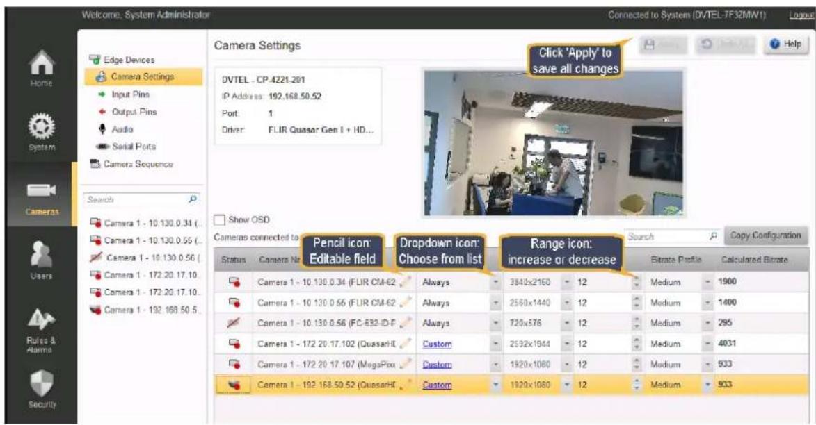
Editing information in Horizon/Meridian Admin Center Screens
4.4 Action Buttons and Help Action Buttons
Where applicable, the system screens have up to three Action Buttons in the top right-hand corner of the screen - Apply, Undo All, and Help
Apply
You can make multiple editing changes on the Settings pages - these will only come into effect when you click the 'Apply' button.
Note: - Once you click the button, changes are applied and you do not have an 'Undo' Last' function.
Undo All
Where you have made changes and do NOT wish to apply them, you can click on the 'Undo All' button, and all your pending changes will be cleared, and the current values will be displayed again.
Help
The system has an extensive context-sensitive Help function. In any screen, clicking the 'Help' button opens a page of information about that screen, with specific information such as explanations about icons used, how to add, edit or delete entries, default values, cautions and notes where required.
If you want to browse the Help topics, you can also access the full Help Table of Contents to find the topic/s you want, or use the Search function to find where a specific term is used.
To open the full Help Table of Contents:
- Open the Help file by clicking on Help in the top right-hand corner of the screen.
- Right-click anywhere in the Table of Contents, and select 'Open All' to see the full Table of Contents.
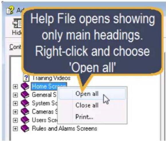
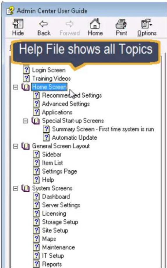
Opening the full Help Table of Contents
5 System Screens
The System icon access the following screens:
Dashboard
Server Settings
Licensing
Storage Setup
Site Setup
Maps
Logical IDs
Maintenance
IT Setup
Reports
5.1 Dashboard
The Dashboard gives a quick status check of the system. The information is divided into several panels - Users, Cameras, and Storage.
![Welcome: System Administrator Dashboard Home System Camera Users Server Settings Licensing Storage Setup Site Setup Maps Logical IDs Maintenance IT Setup Reports Dashboard Help 1. Users 1 login connection User Name User Group Application IP / Hostname System Administrator Administrators Admin Center 172.20.17.105 (DVTEL-7F3ZMW1) Cameras 5 cameras are recording 1 camera is disconnected Camera Name IP Address Recording Mode Status Camera 1 - 172.20.17.102 (Quas... 172.20.17.102 Custom Recording Camera 1 - 192.168.50.52 (Quas... 192.168.50.52 Custom Recording Camera 1 - 10.130.0.56 (FC-632... 10.130.0.56 Always Disconnected Camera 1 - 10.130.0.55 (FLIR C... 10.130.0.55 Always Recording Storage Total defined storage: 1284 [GB] Archiving lifespan: 18 days, 3 hours and 25 minutes Overwriting oldest recording Storage utilization problem](/content/2026/05/914014/images/e526745200428a4a80d356ea2bfd335a00bed5dd6e715ec7acf99d8f5de3561d.jpg)
The Cameras and Storage panels have an icon in the top right corner indicating the current status.
Icon
Icon Description

Status - Good

Status - Caution - check these components
1. Dashboard - Users Panel
| Users 2 login connections | |||
| User Name | User Group | Application | IP / Hostname |
| System Administrator | Administrators | Admin Center | 172.20.12.32 (WS-ROB) |
| System Administrator | Administrators | Control Center | 172.20.12.32 (WS-ROB) |
The User Panel displays the users who are currently logged in to the system and shows which User group they belong to, to which application/s they are currently 'logged in', and from which computer.
2. Dashboard - Cameras Panel
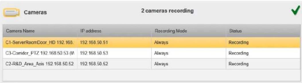
The Cameras Panel shows the currently attached cameras and their status (Connected / Disconnected / Recording).
3. Dashboard - Storage Panel
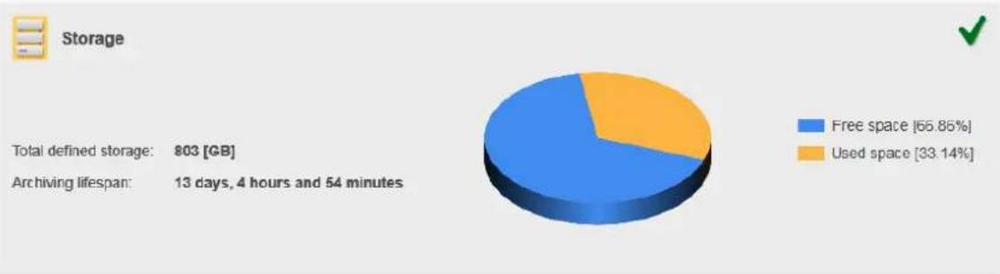
pie
Storage | Category | Percentage (%) | | :--- | :--- | | Free space | 66.85 | | Used space | 33.14 | | Total defined storage: 803 [GB] | | | Archiving lifespan: 13 days, 4 hours and 54 minutes | |The Storage Panel shows the current status of the Storage and the Archiving Lifespan.
5.2 Server Settings
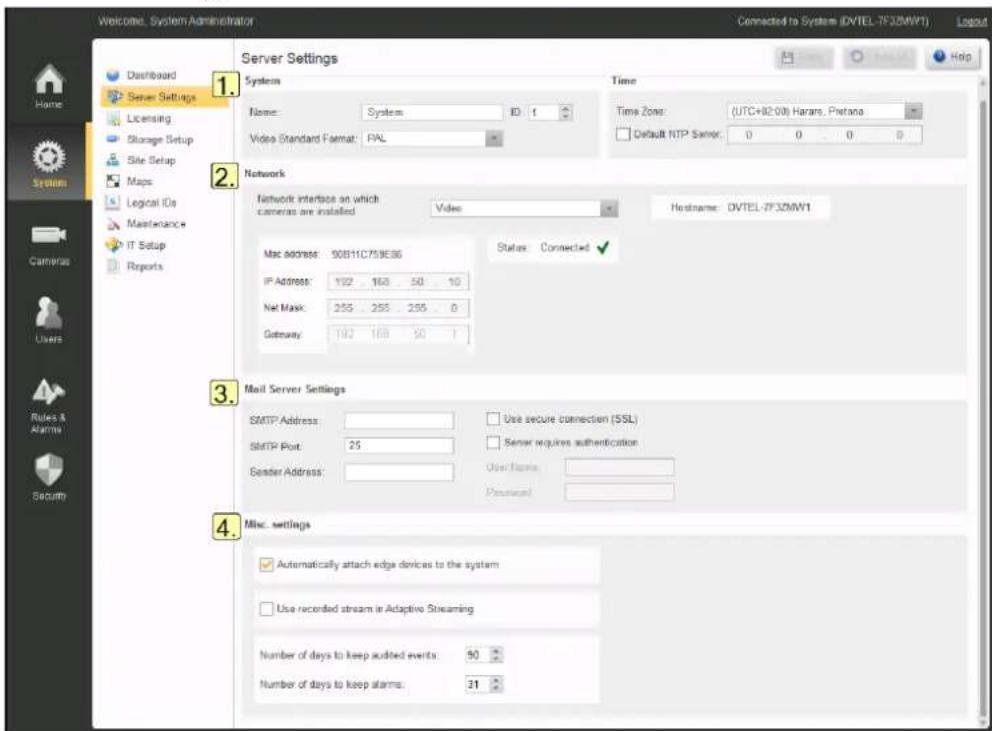
The Server Settings screen is divided into the following areas:
1. System
Set the basic Server definitions:
Name - The default name is 'System'. You can change this if required.
ID - The logical ID used for keypad navigation in the ControlCenter.
Note: If more than one system is to be connected to a Control Center, the Administrator must ensure that each System has a unique system ID.
Video Standard Format - Defines the TV standard default used (NTSC or PAL).
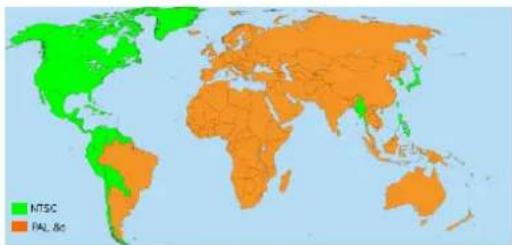
The system is normally configured to match the standard in your area
Time Zone - Must be set to the correct timezone for your system.
Note - This setting modifies the Windows Time Zone setting on the server.
Default NTP Server - If an external Time Server is to be used, check the box and enter the IP address of the NTP Server to be used.
2. Network

Take care to complete all mandatory fields as indicated (*).
Caution:
These parameters should be set up in consultation with the User's IT Department.
Changes should ONLY be made after consulting your Support Manager. Incorrect
changes can cause major problems.
Network Interface on which cameras are installed - This shows the Network Interface Card (NIC) on which automatic discovery of cameras may be implemented. (Setting made when the first-time installation wizard was run).
Hostname - Displays the hostname of the Horizon/Meridian Server. (Information only)
3. Mail Server Settings
Caution:
These parameters should be set up in consultation with the User's IT Department
The Mail Server information allows the system to send email messages automatically (example - generated by Actions associated with Alarms).
SMTP Address - Enter the address of the SMTP Mail server
SMTP Port - Enter the SMTP Port Number
Sender Address -
Use SSL Settings -
Server requires authentication -
The following fields are enabled when authentication is enabled:
User Name -
Password -

Once an address for an SMTP Mail Server has been entered and saved, the system displays the current status of the connection (Connected or Disconnected)
Mail Server Settings
SMTP Address
smtp.exchange.com
□ Use secure connection (SSL)
Status: Connected

SMTP Port.
25
□ Server requires authentication
Sender Address:
usen@exchange.com
User Name
4. Misc Settings
Automatically attach edge devices to the system - Horizon/Meridian runs a continuous scan on the selected NIC and discovers any cameras that have added.

The default DHCP setting is that Horizon/Meridian will act as a DHCP server and will set up IP addresses for cameras and client workstations connected on the VIDEO NIC
Use recorded stream in Adaptive Streaming - Scales video resolution to the size of the video pane.
Number of days to keep audited events - Default 90
Number of days to keep alarms - Default 31
5.3 Licensing
The Licensing screen lists all the current License options for the system.
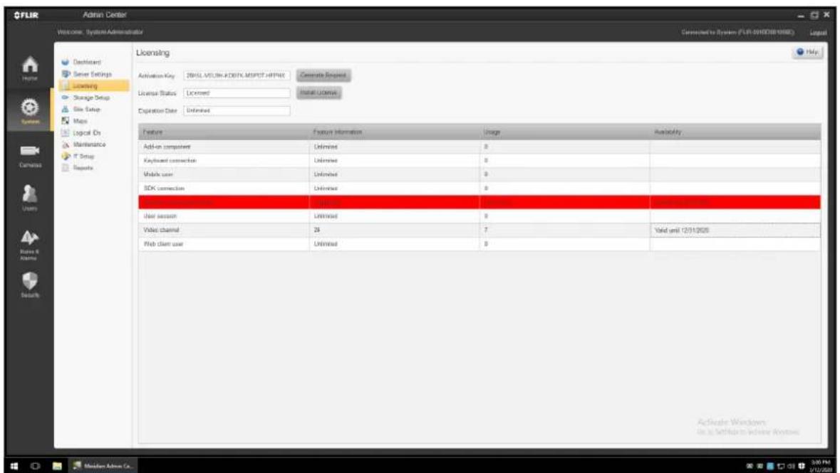
System/Licensing
1. Acquiring or upgrading a license
Note: For details of the licensing process, see the Horizon/Meridian Release Notes.
Summary: The first two lines of the Licensing screen are used when setting up the Horizon/Meridian license.
An Activation Key is provided by the Licensing site. That Key is used to create a Request File. The Request file is used on the Activation site to create a license, and the License can then be installed on the system.
- Expiration Date - displays the validity of the license.
3. License Features table
The table provides full details of all licenses features
Feature Information column - For each entry, this shows the maximum allowed number of licensed instances.
Usage column shows the number of instances of the component/feature that are in use.
Availability column shows the status of the expiration date of a "time-limited" feature. If an expiration date was set for a specific feature, the row will show "Valid Unit [date]". If the expiration date has passed it will show "Expired on [date]"
5.4 Storage Setup
The Storage Setup screen allows you to assign system drives for Video storage and allocate or increase the amount of disk space for video recordings
![Welcome - System Administrator Connected to System (DVTEL-7F3ZMW1) Logout Dashboard Server Settings Licensing Storage Setup Site Setup Maps Logical IDs Maintenance IT Setup Reports Home System Cameras Users Rules & Limits Security 1. 2. Storage Setup Drives settings Assigned Drive Used For Total Size [GB] Available Space [GB] Allocated Size for Video [GB] Videos Usage OS (C) System 79 17 0 0% DB (D) Database 49 47 0 0% Video2 (Y) Data 485 342 464 90% Video1 (Z) Data 801 0 800 67% Total storage allocated for video: 1264 [GB] Video Usage 88% Actual archive lifespan: 21 days, 1 hour and 16 minutes Overwriting oldest recording Recording lifespan settings Search Copy Lifespan Settings to All Camera Behavior Schedule [Days] Motion/Event/Alarm/Manual [Days] Camera 1 - 172.20.17.102 (QuasarHDIPCamera) - 17 Maximum 31 31 Camera 1 - 192.168.50.52 (QuasarHDIPCamera) - 6 Maximum 31 31 Camera 1 - 10.130.0.68 (FC-632-ID-PAL 5269C) - 16 Maximum 31 31 Camera 1 - 10.130.0.55 (FLIR CM-6204-11-I-RO KB16302370) - 16 Maximum 31 31 Camera 1 - 10.130.0.34 (FLIR CM-6208-11-I) - 21 Maximum 31 31 Camera 1 - 172.20.17.107 (MegaPixelCamera) - 20 Maximum 31 31](/content/2026/05/914014/images/bf1c17d1aff5c784a71660b912bc55defe31369894e6e92d4b54c1155b6d99c1.jpg)
The Storage Setup screen is divided into two sections:
Drives Settings and Lifespan Settings:
1. Drives Settings
This part of the screen lets the user choose which drives are to be used by the system, and to allocate how much space to use on each.
All drives available on the Server are listed.
Drive information provided by the system:
Drive (Letter), Used for (System/Data), Total Size (GB), Free Space (GB), Video Usage (%)
Fields accessible to the user:
Assigned - Check the drives that are to be used by Horizon/Meridian server to store recorded video.
Allocated Size for Video - Enter the amount of disk space to allocate (in GB) for video storage. Click Apply for the setting to take effect.
You can increase the amount of disk space allocated for video storage on a drive by editing this field.
Caution:
Once set, the amount of space allocated for video storage on a specific drive cannot be decreased.
2. Lifespan Settings
These parameters set the rules for how stored video is preserved.
Behavior - All cameras connected to the system are listed, and for each camera you can set stored video to be held for 'Maximum' or 'Minimum' days.
• Maximum - (Maximum length of time the recording will be kept.)
The recording will always be removed after the specified number of days. It does not guarantee that it will be available for that period of time.
- Minimum - (Minimum length of time the recording will be kept.)
The recording will be available for that length of time - it may still remain in the system after that, until its space is required for a newer recording.
Schedule - The recording lifespan to be applied for scheduled recording
Motion/Event/Alarm/Manual [Days] - The recording lifespan to be applied when recording was triggered by one of these Event Types (i.e. this may be different from the recording lifespan when recording was Scheduled.
The recording will be available for that length of time - it may still remain in the system after that, until its space is required for a newer recording.
Notes:
- Maximum: 365, Minimum: 1
- There are separate parameters for video that was recorded according to a Schedule, and video that was recorded as the result of a Motion Detection trigger.
Copy lifespans settings to all - If all cameras are to use the same setting, you can complete one line and then click 'Copy Lifespan Settings to All'.

This will copy the parameters to all cameras, but you still need to click Apply at the top of the screen in order for the changes to take effect.
5.5 Site Setup
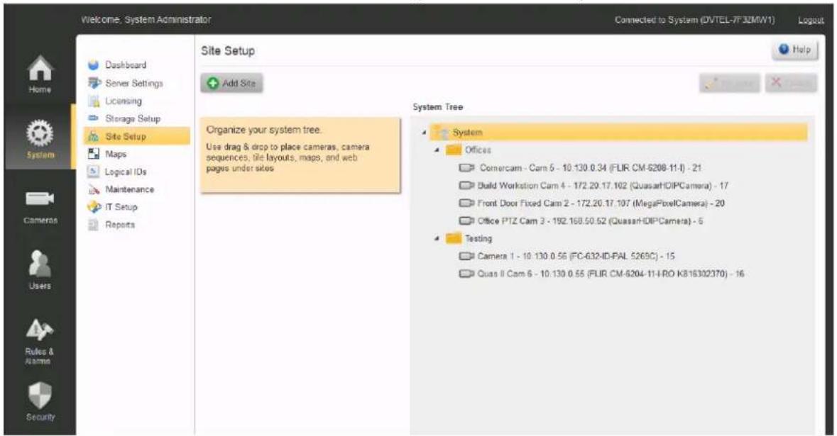
The user can define Sites, and then associate one or more cameras with the Sites. This provides Control Center users with a more logical view of the system.
To Add or Edit a Site
To add a new Site, click on Add Site. The Add Site window will open. Enter the name for the new site. Return to the Site Setup screen, and drag-and-drop entities (cameras, maps, etc.) to create the structure you want.
Note: Drag till you see the 'outline' symbol
When moving an Entity to a site, hold the mouse-button and drag until you see the red 'outline' symbols on the target Site Name
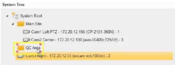
To edit the Site Name, select the site you want to change and click on Rename. Enter the new name, click Save and then return to the Site Setup screen.
To Delete a Site
-
Use the mouse to drag-and-drop all entities that are associated with the Site that is to be deleted to another Site.
-
Select the Site to be deleted and click on Delete ✗ You will be asked to confirm that you want to delete the Site. If there are any entities still associated with the Site, the system will not allow the deletion.
5.6 Maps
This screen allows the user to add map files (backgrounds on which cameras can be 'placed', so that their positions can be displayed). These can be site diagrams saved as graphic files, or Web pages (i.e. external URLs such as Google Maps) (*require user licensing).
'Maps' can also refer to files and URLs that may be used to display information to Control Center operators.
Examples are given below.
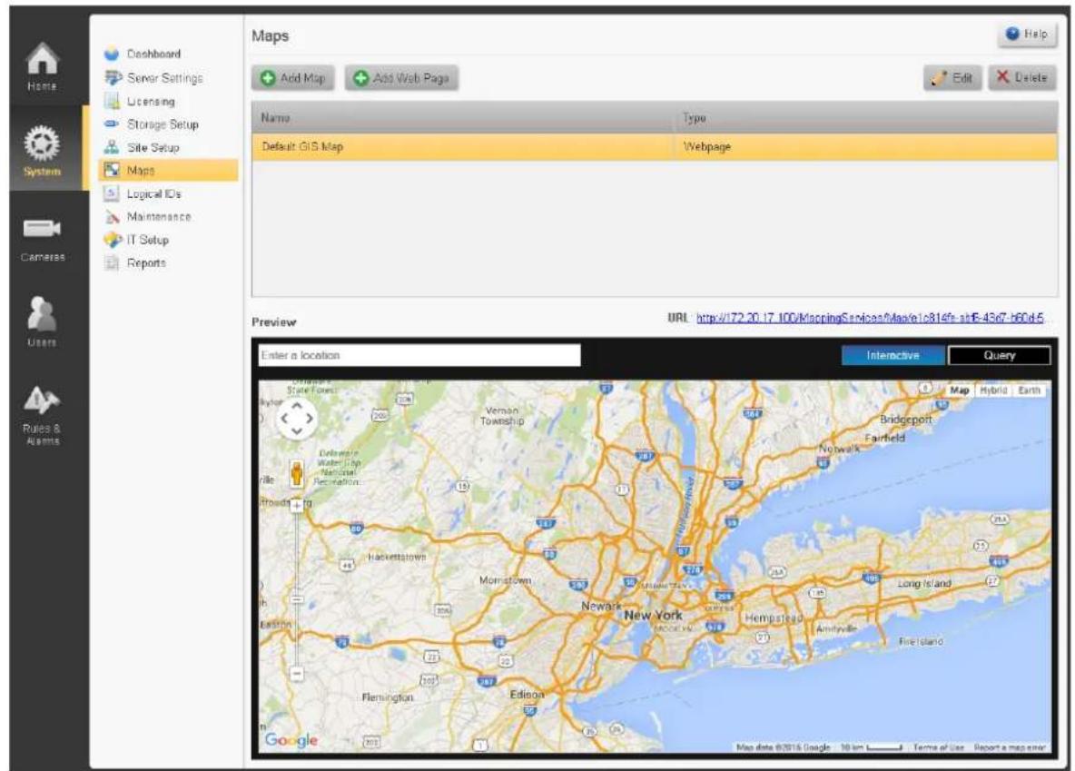
Add Maps Dialog
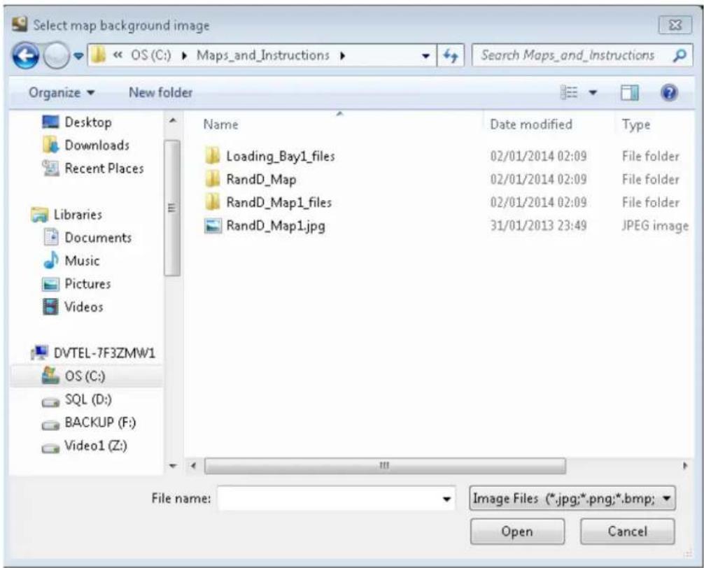
The system will open a Windows Dialog box.
Select the graphics file containing the image to be used (jpg, png, bmp or gif), and click Open.
Once a background image is chosen, the Add Map screen will open.
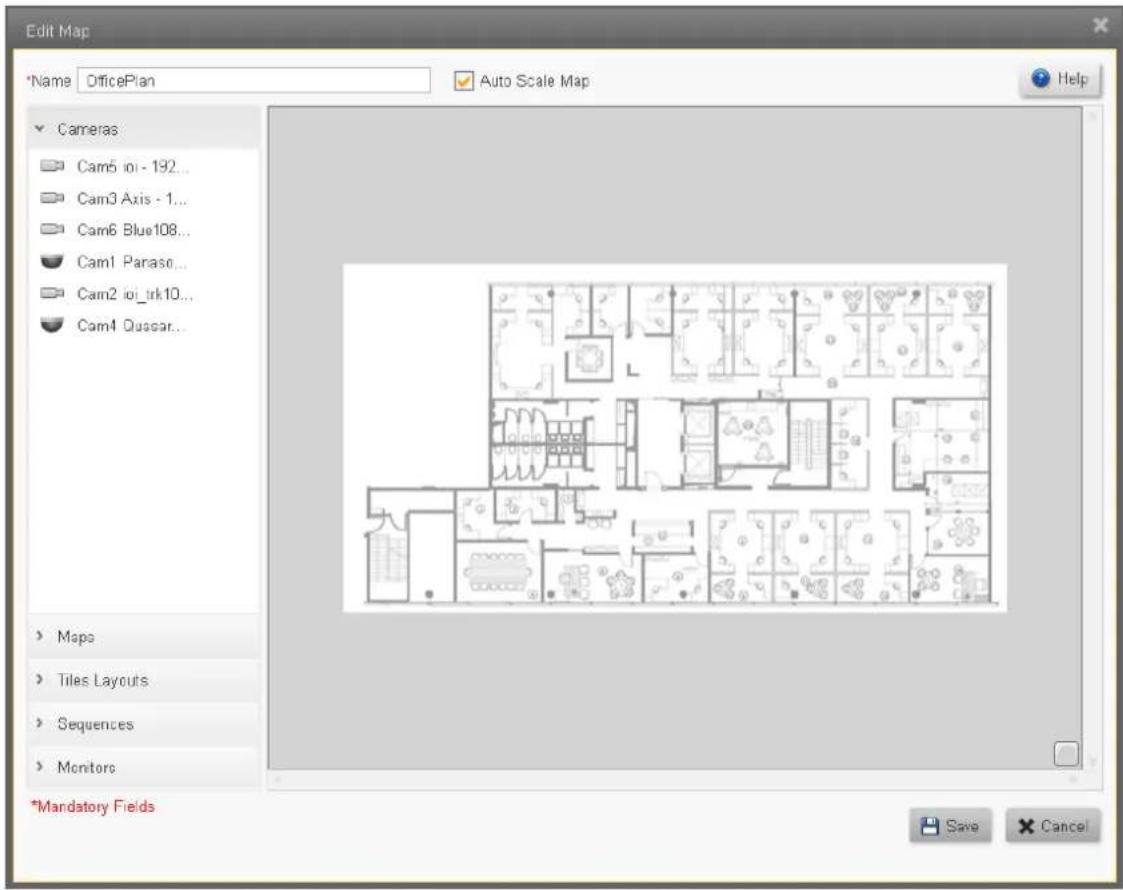
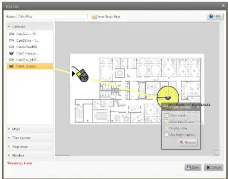
Cameras may be 'dragged' onto the map to indicate their position.
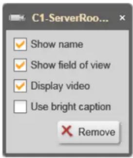
Right-clicking on the camera icon opens a dialog box which allows additional options to be activated.
Option
Control Center Display
Show Camera Name is displayed when the Map is viewed name
Show field of The apparent field of view of the camera is added to the icon.
view
Note - the icon of the camera as it appears on the Map is only an indication - this does not change the actual position, orientation or field of view of the camera.
Display video Hovering the mouse over the camera icon opens a small preview window on the tile displaying the map
Use bright caption Camera Name is displayed in bright font - suitable for dark backgrounds (e.g. Geographic Maps)
Remove Removes this map from the list of Maps
Add Web Page Dialog
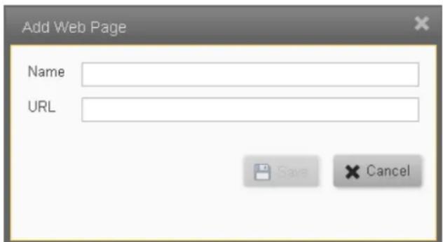
The web page dialog is used to add files or URLs that can be displayed in the tiles of the Control Center.
-
If an external website is to be displayed, then enter use its regular URL in the URL field(e.g. https://maps . . etc).
If a local file is required, erase the 'http://' in the URL field, replace with the full file path (e.g. C:\Folder\subfolder\filename.filetype). -
Enter a Map name in the Name field and click Save.
5.7 Logical IDs
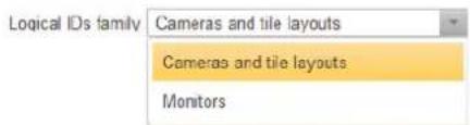
All entities in the system have Logical IDs assigned to them. Horizon/Meridian allows the user to use the Logical IDs that apply to Cameras, Tile Layouts and Monitors. This screen enables the user to view and edit the current Logical IDs assigned to these entities.
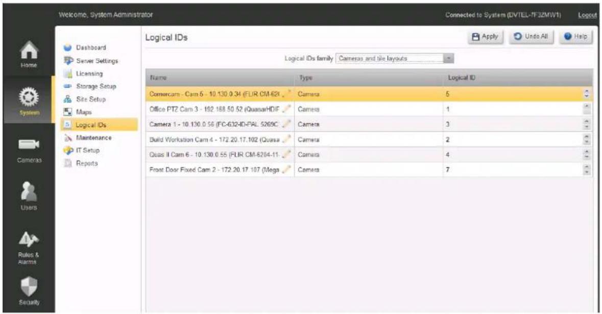
The user selects which family of entities to display using the pulldown box at the top of the screen.
Entity names can be edited in the Name column, and Logical Ids can be incremented/decremented using the control in the Logical Id column.
Logical Ids for each type of entity must be unique - if the user selects a Logical Id that is already in use, the system will not allow the value to be saved, and will display a message indicating that another value must be selected.
Logical Ids are shown in the Control Center and in the Web Client as numeric values following the Entity name.
In the Control Center the user can use either the workstation keyboard or a CCTV Keyboard to control a display. Details are provided in the Control Center Help file.
5.8 Maintenance
The Maintenance links allow the user to export log files and to do manual or scheduled backups of the database.
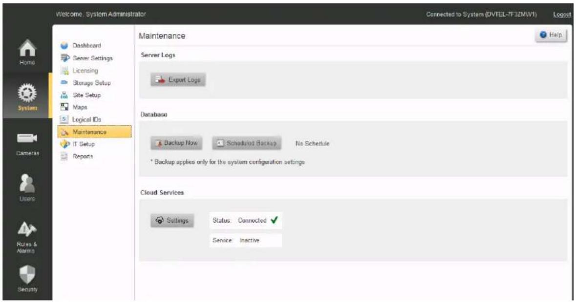
Server Logs
To Export Logs - click on the Export Logs button Export Logs
The system will open a Windows File window, pointing at the default location, and giving a file name 'Horizon/MeridianLogs.zip'. Edit if necessary, and click Save.
Database
To Backup the Database immediately - click on the Backup Now button
The system will open a Windows File window, pointing at the default location, and giving a file name 'Horizon/MeridianDB.zip'. Edit if necessary, and click Save.
To Create/modify the Schedule for database backups
- Click the Scheduled Backup button 📄 Scheduled Backup The system will open the Schedule backup window.
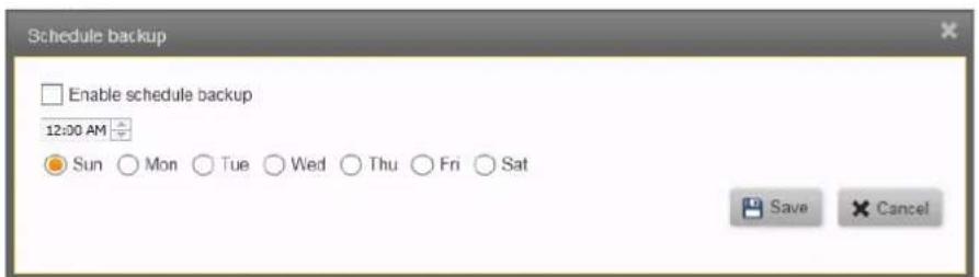
-
Check 'Enable schedule backup' to initiate scheduled backups.
-
Set the time for backups to be made, and check the day/s on which the backup should be run.
-
Click the Save button.
The system will display the time, date, and path for the Database backups.
e.g. 'Next schedule on: Sunday, May 19, 2013, 12:AM'
'Server Backup Path: C:\Program Files\System Designation\Directory\Backup'
Cloud Services
Users must have registered for FLIR's Cloud Services and must have a current in-force SSA Agreement.
Please consult your Service Representative for further details of using FLIR's Cloud Services.
5.9 IT Setup
The system uses several external interfaces. The IT Setup screen initially shows the system's default networking parameters.
Caution:
Alternative values may be set where necessary. All networking related parameters should only be set up after consultation with your FLIR Systems, Inc representative and your IT Department
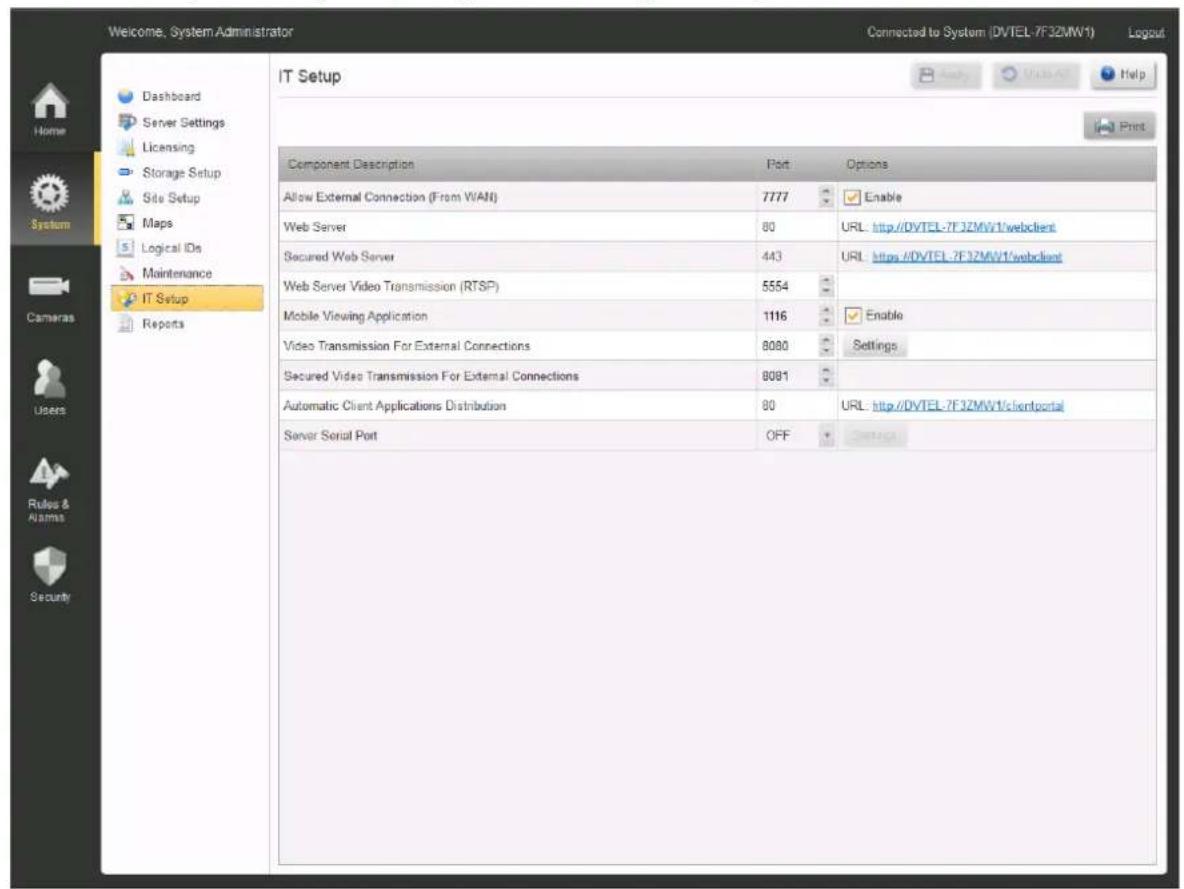
The system displays all the current network port settings used by the Horizon/Meridian server for the features listed.
Allow External Connection (From WAN)* - Default: Disabled - Allows client workstations running Horizon/Meridian Admin Center and/or Control Center applications to connect from the Internet.
Web Server - used to support connections from Web Clients (information only, cannot be changed)
Secured Web Server - port allocated for TLS communication
Web Server Video Transmission (RTSP)* - used to stream video to web clients.
Mobile Viewing Application* - Default: Enabled - Allows connections from Horizon/Meridian-supported mobile video applications.
Video Transmission For External Connections* - used for sending video to client workstations and Horizon/Meridian-supported mobile applications connected from the Internet.
Secured Video Transmission for External Connections - port for encrypted transmissions to Web Clients
Note: For setting up TLS, see Server Settings / IP Security
Settings - Clicking on the Video Transmission Settings button opens a Dialog box allowing the user to change the default quality settings for external video streaming.
Automatic Client Applications Distribution - used by Horizon/Meridian when updating Client Application software (information only, cannot be changed)
Server Serial Port - used for connecting external systems such as Access Control, Building Management. After selecting a COM port using the drop-down box, the Settings button will be enabled.
Click on the Settings button to select the communication protocol and parameters to be used.
* Important Note: Enabling access to the internal network (LAN) from the Internet (WAN) requires advanced networking knowledge. Changes to these settings should only be made in consultation with the IT department and your support representative.
After making any change, the user must click the Apply button.
The Undo button will clear all unsaved changes and re-display the stored settings.
After applying changes, press the Print button to print out all the information.
Clicking on this button opens the Windows Print dialog window, select a printer and press "Print".
Keep the printed list available for IT and Support staff.
5.10 Reports
The Reports screen allows the user to produce a range of reports either using simple default settings, or, depending on the report, setting specific parameters.
- Click to show/hide instructions for first-time access to the Report Generator

The first time this screen is opened, the user must accept the Adobe End User License Agreement (See below).
If the user declines the terms of the Agreement, the Report Generator will be disabled.
To reinstate the EULA and accept the conditions, use the File Explorer to navigate to the folder
"C:\ProgramData\FLIR\VMSInstallCache..[Current version]..
\ISSetupPrerequisites",
and run the program "AdbeRdr11002_en_US\AdbeRdr11002_en_US.exe"
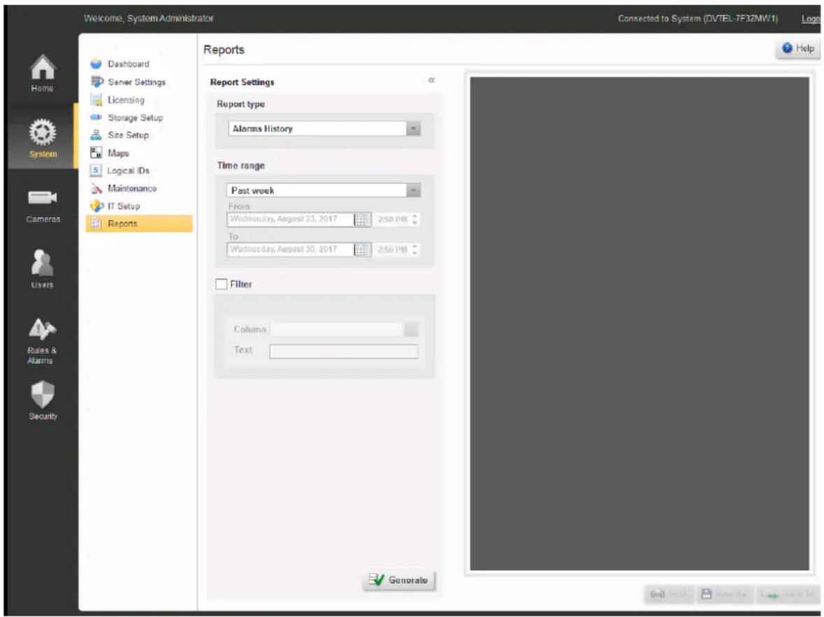
The available reports are listed in the Report Type drop-down.
| Report Type | Parameters | Filter Parameters Available |
| Alarms History | Time RangeLast 24 hours, Past Week, Past Month.Manual selection – Enables the user to enter a custom time range. | By Column and Text |
| User LogonHistory | Time RangeLast 24 hours, Past Week, Past Month.Manual selection – Enables the user to enter a custom time range. | By Column and Text |
| SignOff | No Parameters. Produces a report which can be signed off between Integrator and User, giving summary of the Installation. | |
| System Status | No Parameters. Produces a System summary. |
The << symbol allows the display area to be enlarged.
Click on Generate to create a Report.
Once a report has been generated, the report will be previewed on the screen, and the Print and Save As fields will be enabled. Provided the Mail Server Settings were set in the Server Settings screen, the Send To field will also be enabled.
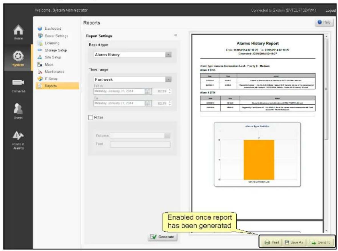
Print Opens a standard Windows Print dialog, allowing the report to be printed.
Save As Opens a File Explorer dialog, allowing the report to be saved.
Send To Opens an Email dialog. Users with addresses stored in the system may be selected, and/or full email addresses of others may be added.
6 Cameras Screens
The Cameras button accesses the Edge Devices screens
Edge Devices - this screen summarizes all Edge Devices connected to the system. More details about Edge Devices are shown in the following screens:
- Camera Settings
○ Input Pins
○ Output Pins
○ Audio
Serial Ports - Camera Sequence
- Camera List
6.1 Edge Devices
The Edge Devices screen provides a complete list of all edge devices (and details of their subcomponents) currently connected to the system, shows whether they are currently 'attached', and gives their basic device details.
After making any change, the user must click the Apply button.
The Undo button will clear all unsaved changes and re-display the stored settings
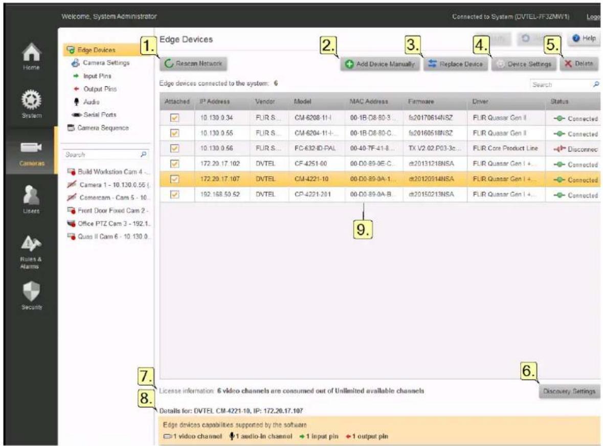
Cameras/Edge Devices
1. Rescan Network
Horizon/Meridian regularly scans the system's default network (defined in the Server Settings screen) and adds any new devices it finds. If the rescan icon is turning, this means a scan is in progress, and you may need to wait until it is complete before new devices are shown.
Pressing the Rescan Network button causes a rescan to start immediately.
Note: Devices that are not on the default network will NOT be discovered by the automatic scan, and must be added manually (see below)
2. Adding Devices Manually - See the separate topic Adding New Devices
3. Replacing Devices
a. Select the device to be replaced,
b. Click Replace Device.
A window opens showing all devices available (i.e. having the same Vendor and Model).
c. Select the device that you wish to use instead of the current one, and click Save.
Note: Where a replacement device has already been set with the same IP address as the selected one and connected to the system, it will be discovered by the automatic rescan and its entry in the Replace Device screen will be in bold font.
4. Device Credentials
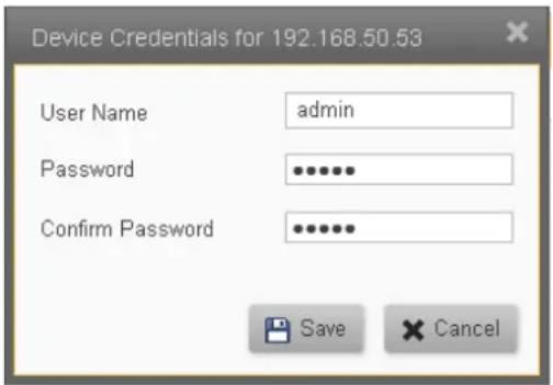
Clicking on this button shows the Device Credentials to be used by the system for the connecting to the selected device. These stored credentials can be modified and saved.
Note: This does not change the credentials in the device - it only affects the stored credentials that the system uses when connecting to the device.
5. Delete
Click on the Delete button to delete the currently selected device. You are asked to confirm that you want to delete it.

Caution: Deleting a device from the Edge Device list completely removes the device its and all recorded material associated with it.
If you subsequently rediscover the same device (Manually or with the automatic resca no previously-recorded material can be recovered.
If, instead of Deleting, you deselect the 'Attached' box, the entry remains in the table, a recordings are accessible.
6. Discovery Settings
This button opens the Discovery Settings dialog box where you can specify the type of device scanning to be performed (Proprietary or ONVIF), and the vendor/model ranges to be included in the scan. The scan settings and credentials that will be used for the vendor/model range of the selected (highlighted) device are shown.
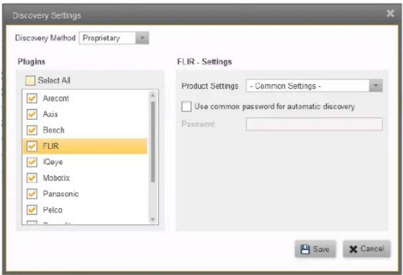
Checking the Select all check-box will cause the system to scan for all possible vendor/model ranges. Normally, one should check only those Plugin entries that need to be scanned. This will make the scanning process quicker..
When the FLIR check-box is checked, this allows scanning for all FLIR Core Camera Products, as indicated by the Common Settings entry in Product Settings
Note: FLIR Recorders are an exception to this rule - FLIR Recorders cannot be discovered automatically, and user should use the Add Device Manually option to discover them.
If the user wishes to make changes to the stored settings for a product group, the appropriate entry in the Plugin list can be selected and the stored settings for that product or group will be displayed.
Similarly, by highlighting an entry in the Plugin list, the Plugin Settings for that Product Group are shown, and the user then has the opportunity to enter any special values as required. These may include User Name, Password, Port, Begin/End Port, etc.
After pressing Save, the settings are used for the automatic scanning process. Devices that have been added are shown when the next scan is completed. If required, you can click on Rescan Network to force a rescan to start.
7. License information
The system shows the total number of channels for which the system is licensed, and the number of channels currently being consumed.
8. Details for:
(Model and IP address of selected device)
The Name, IP Address, and supported device capabilities for the selected device are displayed.
9. Edge Devices Details:
The table displays the following details:
- Attached - Indicates if the edge device is currently attached to the system.
- IP Address - The edge device IP address.
■ Vendor - The device supplier.
■ Model - The device model. - MAC Address - The device Media Access Control (MAC) address.
- Firmware - The device software version, used to communicate with the system and other devices.
- Driver - The specific driver the device is using.
- Status - Indicates the device status (Connected, Connecting, Disconnected)
6.1.1 Input Pins
The Input Pins screen shows a list of all input pins on attached devices.
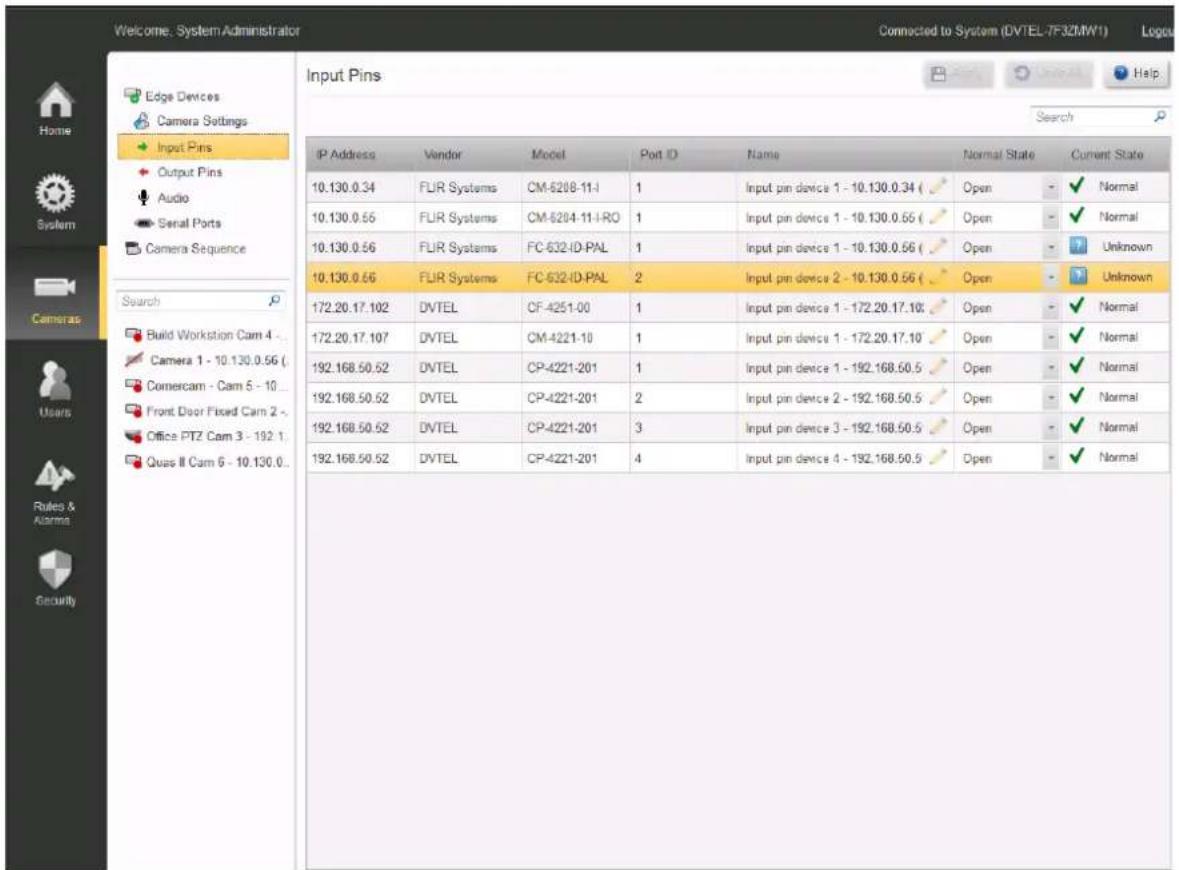
Cameras/Edge Devices/Camera Settings/Input Pins
The IP Address, Vendor, Model and Port Id are indicated.
The default Name is shown - this can be edited if required.
A drop-down menu in the Normal Status field allows the pin to be set to Open (NO) or Closed (NC). Depending on this setting, the adjacent field indicates the current state of the pin.
After making any change, the user must click the Apply button.
The Undo button will clear all unsaved changes and re-display the stored settings.
6.1.2 Output Pins
The Output Pins screen shows a list of all output pins on attached devices.
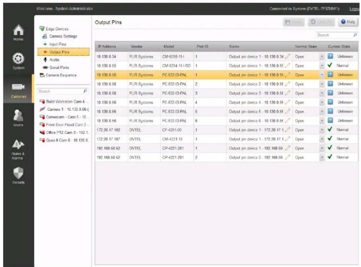
Cameras/Edge Devices/Camera Settings/Output Pins
The IP Address, Vendor, Model and Port Id are indicated.
The default Name is shown - this can be edited if required.
A drop-down menu in the Normal Status field allows the pin to be set to Open (NO) or Closed (NC). Depending on this setting, the adjacent field indicates the current state of the pin.
After making any change, the user must click the Apply button.
The Undo button will clear all unsaved changes and re-display the stored settings
6.1.3 Audio
The Audio Ports screen shows a list of all attached Edge Devices with Audio Ports.
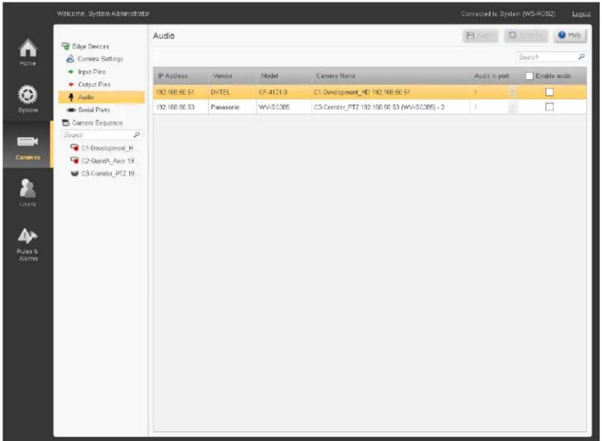
Cameras/Edge Devices/Camera Settings/Audio
The IP Address, Vendor, Model and Camera Name are indicated.
The user can select which Audio Port on the camera is to be used (1,2).
Clicking a box in the Enable Audio column activates/deactivates the audio port for the selected device.
Clicking the box in the Heading row will enable/disable all audio ports.
After making any change, the user must click the Apply button.
The Undo button will clear all unsaved changes and re-display the stored settings
6.1.4 Serial Ports
The Serial Ports screen shows a list of all Serial Ports on attached devices.
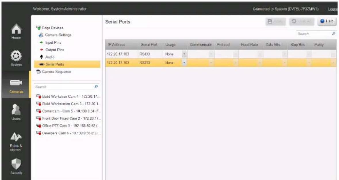
Cameras/Edge Devices/Camera Settings/Serial Ports
The IP Address and Serial Port type (RS232, RS4xx, .. ) are indicated.
The user can select the required values for the Serial Port Parameters listed below.
Serial Port parameters
Usage - (None, Keyboard, PTZ)
Communications - (RS-232, RS422 4 wire/2-wire, etc)
Protocol - (DVTEL, Pelco, American Dynamics)
Bitrate - (75, 110, . . . . . , 912600)
Data Bits - (7,8)
Stop Bits - (1, 2)
Parity - (None, Odd, Even)
After making any change, the user must click the Apply button.
The Undo button will clear all unsaved changes and re-display the stored settings.
6.1.5 Adding New Devices
The Add Device Manually button allows you to add devices that are not on the default network. Clicking the button opens the Add Devices dialog box, where you can specify an IP address and choose a Vendor/model range.
The default credentials for the selected vendor/model range are shown.
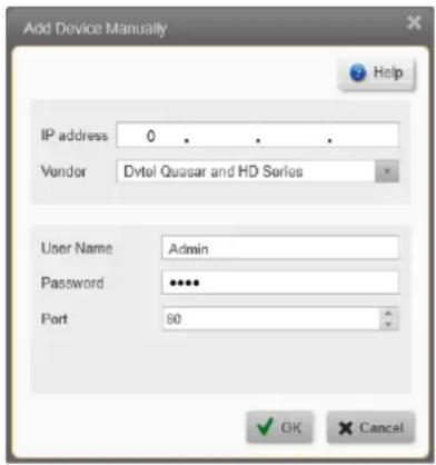
The dialog box allows the user to enter an IP address and select a Vendor/model.
The default login information for the device is displayed, depending on what is required for the particular device.
6.2 Camera Settings
Camera Settings - This screen is used to view and configure the most common settings for all the cameras currently attached to the system.
The table shows all the cameras currently attached to the system, their current status, and their most important settings. You can select a particular camera in the table, preview its output, and edit its basic parameters.
To view and/or edit more detailed camera parameters, select the camera in the item list.
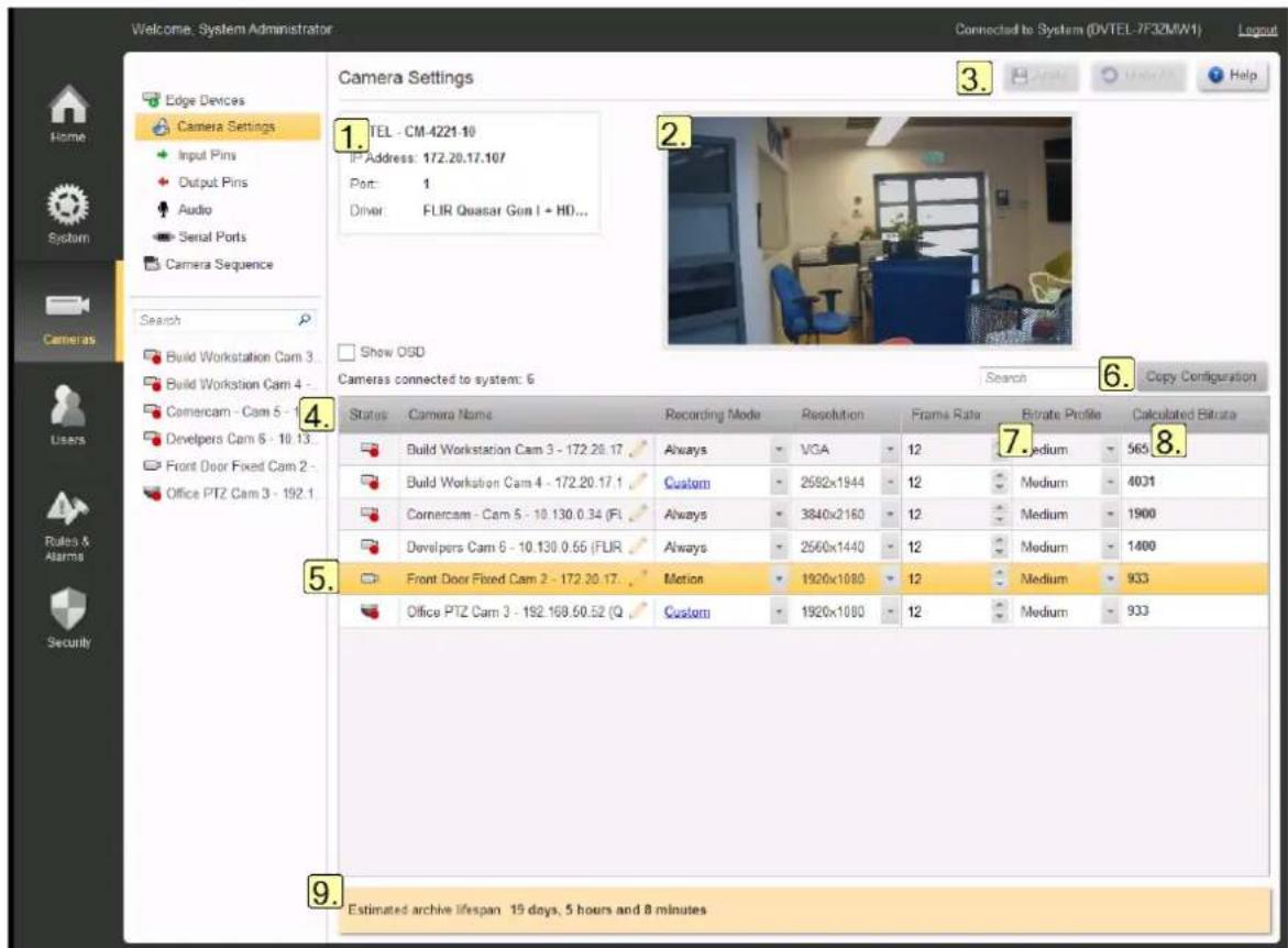
Cameras/Edge Devices/Camera Settings
| Selected Camera | Preview Window | Apply/Undo |
| Table of All Attached Cameras | Selected CameraCopy Configuration Details | Button |
| Calculated Bitrate | No. of Streams | Estimated Archive Lifespan |
1. Selected Camera
The Camera Name, IP Address, and Driver Details for the selected camera are shown.
2. Preview Window
The preview window shows the selected camera's output
Show OSD - When this box is selected, OSD information displays for this camera.
3. Apply / Undo
After making any change, the user must click the Apply button.
The Undo button will clear all unsaved changes and re-display the stored settings
4. Table of all Attached Cameras
Click on any camera in the list to 'select' it.
5. Selected Camera Details
The selected camera's details and preview are shown, and the parameter fields in the table can be edited. Drop-downs indicate where other parameters may be selected. Only values that are valid for the selected parameter are shown. Where parameters are disabled (grayed out) this indicates that no other choices are available
Status - Cameras can be in the following states:
- Connected (receives camera video stream)
- Disconnected (is not receiving camera video stream)
- Recording
(see full List of possible Camera States)
Camera Name - The system assigns a default name when the camera is discovered. You can edit this field to put in a camera name of your choice
Recording Mode - Choose Off, Always, Motion or Custom.
(For Custom, see Recording Schedule)
(For Cameras with Basic Analytics enabled, see Basic Analytics
Resolution, Frame Rate and Compression Quality - pull-down lists give the values that are available. The options available depend on the characteristics of the individual cameras.
6. Copy Configuration Button
This opens the Copy Configuration dialog box, where you can take all or some values from the selected camera, and apply them to one or more other connected cameras in the system
7. Calculated Bitrate
The system shows the bitrate that each camera will use, based on the selected Resolution, Frame Rate and Compression Quality.
8. No. of Streams
Indicates if the camera is supplying separate streams for Live viewing and for Recording. Characteristics of the recorded stream are available as a tooltip, shown by hovering the mouse over the No. of streams entry for the relevant camera. Note: The No. of Streams column is only shown if one or more cameras have the Dual Stream feature enabled.
9. Estimated Archive Lifespan
The system displays the calculated storage capacity based on the amount of storage allocated and the camera parameters that have been chosen
6.2.1 Recording Schedule
To create or update a Recording Schedule for a Camera:
- Select Cameras in the Sidebar, select Camera Settings, and select the required Camera from the table.
- In the Recording Mode column, use the drop-down to select Custom.
- Click on the 'Custom' link. The following Recording Schedule dialog opens.
Use the Recording Schedule dialog to set up or modify interval patterns during which the Recording is activated.
Each camera can have its own schedule.
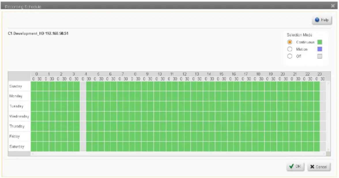
bar
Recording Schedule C1.Development_HD 192.168.50.51 Selection Mode Continuous Motion Off Sunday Monday Tuesday Wednesday Thursday Friday Saturday OK CancelThe Recording Schedule is indicated by the color of the blocks in the schedule table. All cameras are initially set to the default 'Continuous' schedule - as shown by the continuous green blocks.
To Create a new Schedule:
- From the Device drop-down, select the camera for which the schedule is being created.
- In the Selection Mode area, choose the radio button for the type of Recording required. Select from the following:
Continuous - This is the default - Initially, all blocks in the schedule show 'Continuous'. If necessary, after you have added other modes, you can always go back and reset some of the schedule to 'Continuous'.
Motion - The camera records when Motion is detected (including the pre- and post-event recording - see Camera Motion Settings parameters of the Camera - Detailed Settings for Motion Detection, Video, Picture and PTZ screen).
Off - The camera does not record.
- Use the mouse to click and drag through times and days during which the selected mode applies - the color in the selected blocks changes to indicate the selected mode, 'Continuous', 'Motion' or 'None'.
Note: When a camera "Recording Mode" is set from "Always" to "Custom", in the Recording Schedule dialog, in the Selection Mode area, you must select "Off" and then deselect the time intervals (days and hours) that you want turned off. The selected days and hours change from green and are indicated in gray.
- If required, you can then set a different Recording Mode using the radio buttons, and add additional time blocks in the schedule.
- When the schedule is complete, click OK.
To Edit an exiting Schedule
- Select the camera for which the schedule should be edited by clicking on it in the list of cameras.
- Edit the blocks in the schedule.
- When you have made the required changes, click OK.
6.2.2 Copy Configuration
The Copy Configuration dialog box allows the user to copy one or more settings from an existing camera to additional camera/s.
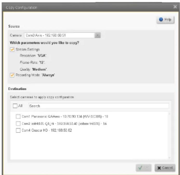
Cameras/Edge Devices/Camera Settings/Copy Configuration
Source
When you enter the Copy Configuration dialog box, the selected camera in the Camera settings screen will appear as the Source. You can select a different Source from the dropdown list of cameras.
The list of Stream Settings parameters (Resolution, Frame Rate, and Quality), and Recording Mode shows those parameters that will be copied from the source camera. The parameters making up the list will vary according to the vendor/model of camera selected, and the values for those parameters as set in the source camera will be shown. Check whether to copy the Stream Settings parameters and/or the Recording Mode setting. If you do not select a parameter, then the Destination cameras' default value for that parameter will be used.
Destination
The Destination field lists all the attached cameras that are capable of using the selected source parameters.
All / Search Filter - The All check-box allows you to select all the listed cameras.
Otherwise you can check just those cameras that you want to use the selected camera's parameters.
Entering text in the Search Filter will reduce the list of available cameras and show only those possible Destination cameras whose Names have text that corresponds to the text entered.
Note when dealing with cameras that may have their Dual Stream capability enabled.
When copying parameters from a source camera that only has one stream running, the destination cameras will have their second stream disabled by the Copy action.
When copying parameters from a source camera that has two streams running, the destination cameras will have their second stream enabled by the Copy action.
Click OK to apply the chosen settings to all the selected cameras.
6.2.3 List of possible Camera States
Status - Camera status in the table can be shown as one of the following:
IP Fixed Camera
IP PTZ
Description
| Connected |
| Recording |
| Disconnected |
| Recording failed |
| Encoder & Camera | Encoder & Camera | Description |
| Has warning (connection from camera to encoder is lost) | ||
| Recording has warning (connection from camera to encoder is lost) |
6.3 Camera Sequence
A Camera Sequence allows several cameras to be displayed one after the other in a single tile of the Control Center.
![Welcome, System/Administrator Connected to System (DVTEL-7F32MW1) Login Camera Sequence Add Camera Sequence Camera Sequence List Workstations 1 Search Build Workstation Cam 3... Build Workstation Cam 4 -... Comercam - Cam 5 - 10... Developers Cam 6 - 10.13... Front Door Fixed Cam 2 - Office PTZ Cam 3 - 192.1 Sequence items Cameras Dyroll Time [Sec] PTZ Frisset Comercam - Cam 5 - 10 130.0 34 (FLIR CM... 5 Build Workstation Cam 4 - 172.20.17.102 (Qua... 5 Build Workstation Cam 3 - 172.20.17.103 (ax... 5 Help Edit Delete](/content/2026/05/914014/images/922e4d0bdbefde6c7a06def25c1dceaca8e99379dc7513e70f51cc4a1a5e52be.jpg)
The Camera Sequence screen displays a list of the Camera Sequences that have already been configured in the Item list.
The cameras making up the selected Camera Sequence are displayed in a table in the Camera Settings Page, with each camera showing the time for which it will be displayed (the 'dwell time'). A preview window shows the Camera Sequence as it will appear in a Control Center tile.
To Add a new Camera Sequence
- Click the Add Camera Sequence button The Add Camera Sequence window will open.
![Add Sequence Sequence Name Alternate QA Cameras Camera List Cam5 lol - 192.168.50.53 Cam3 Axis - 192.168.50.51 Cam1 Panasonic QAArea - 10.7 Cam2 lol_trk101 QA_Hi - 192.16 Cam4 Quaser HD - 192.168.50.54 Camera 1 - 192.168.50.54 (Altit) Cam1 Panasonic QAArea - 10.70.90.134 (WV-SC385) - 18 Cam1 Panasonic QA... Dwell Time [Sec] PTZ Preset Cam1 Panasonic QA... 5 *Mandatory Fields Save Cancel](/content/2026/05/914014/images/8f032d2304637a835d3caabaf06363dcab9d1bed671dd9b4e5f536c4e4db161f.jpg)
- Enter a Name for the Camera Sequence.
- Add or remove cameras by using the left and right arrows.
- Set the Dwell Time (and Preset parameters if required).
- Arrange the order of the cameras in the sequence using the up- and down-arrows. When you have made the required changes, click on the Save button.
To Edit a Camera Sequence
-
Select the sequence to be edited by clicking on it in the Camera Sequence List.
-
Click the Edit button , Edit
The Edit Sequence window will open.
![Edit Sequence Sequence Name QA Cameras Sequence Camera List Cam5 ioi - 192.168.50.53 Cam3 Axis - 192.168.50.51 Cam1 Panasonic QAArea - 10.7 Cam2 ioi_trk101 QA_Hi - 192.16 Cam4 Quasar HD - 192.168.50.4 Camera 1 - 192.168.50.54 |Altitu Cameras Dwell Time [Sec] PTZ Preset Cam2 io_trk101 QA_... 5 Cam4 Quasar HD - 1... 5 *Mandatory Fields Save Cancel](/content/2026/05/914014/images/5a111695b874f4bbf277c03e42727f9dadc6c314103b5d9b3a0d9b6ef6d7f383.jpg)
- You can make the following changes:
a. Edit the Name of the Sequence.
b. Add or remove cameras by using the left and right arrows.
c. Change the Dwell Time or Preset parameters.
d. Change the order of the cameras in the sequence using the up- and down arrows.
- When you have made the required changes, click on the Save button.
To Delete a Camera Sequence
-
Select the Sequence to be deleted by clicking on it in the Camera Sequence List.
-
Click the Delete button ✗ Delete
You will be asked to confirm that the Sequence is to be deleted.
6.4 Camera List
The Camera List shows all the cameras that are currently attached to the system.
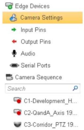
You can then select an individual camera and show its details in the Camera Details screen.
When a camera is selected, the Camera Details screen is shown. Clicking on each of the tabs (Video Settings, Picture Settings, PTZ), displays the corresponding settings.
Note: If the camera selected is not a PTZ camera, the PTZ tab will be disabled.
6.4.1 Camera - Detailed Settings Tabs for different Camera Capabilities
The detailed settings of the selected camera are shown.
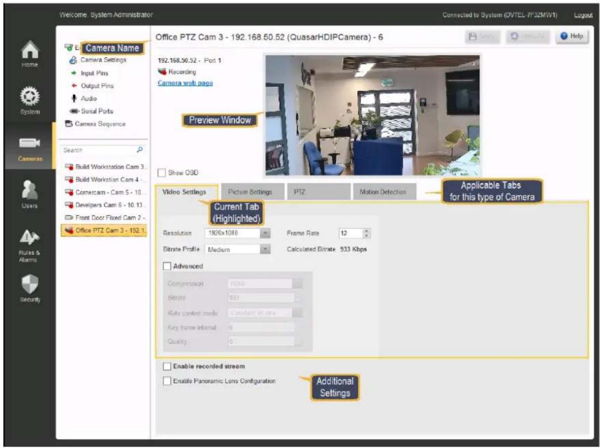
Cameras are initially set with default parameters. Drop-downs indicate where other parameters may be selected. Only parameters that are valid for the selected parameter are shown. Where parameters are disabled (grayed out) this indicates that no other choices are available.
1. Camera Name
The top of the screen shows the selected Camera Name and the regular Horizon/Meridian buttons allowing the user to Apply or Undo any changes that have been made, and to access the Help system.
2. Preview Window
The Preview Window shows the live image from the selected camera.
The paragraphs below provide more information
Available Tabs
The following Settings Tabs present the corresponding parameters for the selected camera. The selection of tabs shown will vary according to the capabilities of the camera.
Video Settings
Picture Settings
Thermal Settings
PTZ Settings
Motion Detection Settings
Analytics Settings
Enable Panoramic Lens Configuration
This tab allows activation of panoramic ("Fisheye") lens capability, when a suitably-equipped camera (such as the Quasar Gen 2), is used or where the associated camera is fitted with a suitable lens..
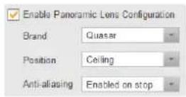
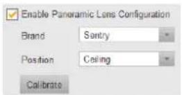
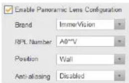
Depending on the type of camera, the applicable list of parameters is shown.
| Parameter | Description |
| Brand | Quasar, Sentry, Immervision |
| RPL Number | Select the appropriate Lens Model(Only shown if Immervision) |
| Position(Orientation of camera) | Ceiling,Ground,Wall (not available for Sentry) |
| Anti-AliasingCalibrate | Enable/Disable (Not available for Sentry)(Only required for Sentry) |
6.4.1.1 Video Settings
By default, the Video Settings tab is always selected when going to the Camera Screen. If one of the other tabs has been selected, the user can return to this tab by clicking on it.
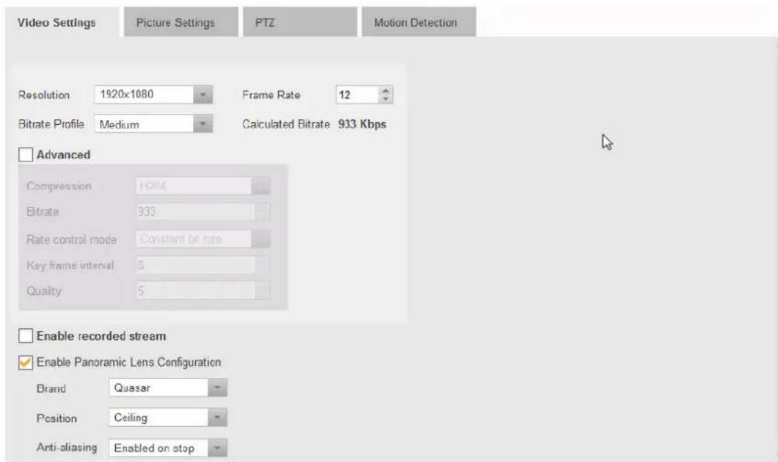
Note:
Resolution, Frame Rate and Compression Quality - Default settings are assigned by the system when the camera is discovered. These should generally not be altered.
Calculated Bitrate - This value is provided by the system.

Enable recorded stream (Click for more detail)
When enabled, this check-box indicates that the selected camera supports dual-stream output. This allows different resolutions to be set for the two streams, so that, for example, a high-definition image can be used for live viewing, and a lower-resolution image (which will consume less archive space) can be stored.
Checking the box opens a second set of Camera Settings parameters, where the characteristics of the recorded stream can be set.
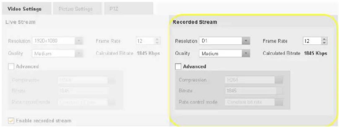
Saving your Settings
Select the required settings, and then click Apply.
Once the settings have been applied, then the details can be seen in a tooltip that is available in the Camera Settings screen, by hovering the mouse over the 'No. of Streams' entry for the relevant camera.
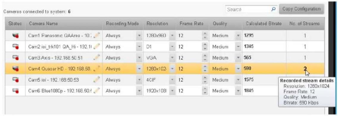
6.4.1.2 Picture Settings
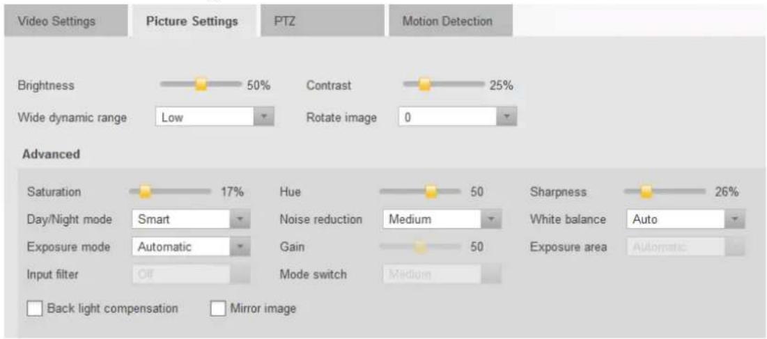
Setting up the best picture
Brightness, Contrast - These two settings are generally adjusted by the user - move the sliders to obtain the best picture in the Preview window.
Default settings are assigned by the system when the camera is discovered. These should generally not be altered.
Other parameters
Wide Dynamic range - This parameter is only enabled for cameras that support the feature.
Rotate Image - Set this parameter to give correct orientation to the picture.
Advanced Settings - Checking this box enables access to the Advanced Settings.
Saving your Settings
Select the required settings, and then click Apply.
6.4.1.3 Thermal Settings

Note: This Tab is only shown when the selected Entity is a Thermal Camera
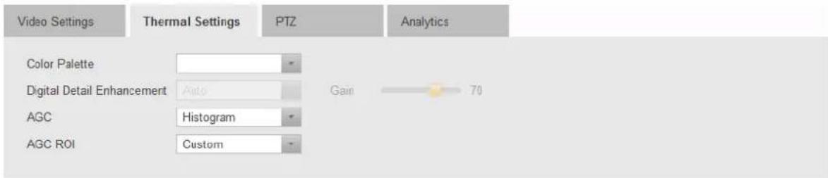
The parameters that may be set are:
Color Palette - The dropdown allows a choice of stored color tables that define different ways to display the Thermal image. Each camera model may have its own set of color palettes. The user should select the palette most suited to the particular situation.
Security cameras will most often display scenes using palettes that provide white-on-black or black-on-white images, while for display of industrial images, the color alternatives might be more useful.
The examples below show how a particular camera (in this case, a PT-334 Thermal Head) display the same Thermal scene using different lookup tables.
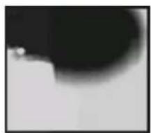
natural_image
Abstract grayscale image with a dark circular shape and a small white dot, no text or symbols present.Lookup Table 1
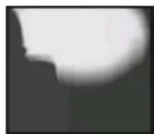
natural_image
Abstract grayscale image with a bright white arc and dark shadow (no text or symbols)Lookup Table 2
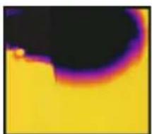
natural_image
Thermal imaging view showing a yellow background with a dark curved region (no text or symbols)Lookup Table 3
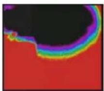
natural_image
Abstract color gradient image with red, black, and purple hues (no text or symbols)Lookup Table 12
DDE - (Digital Detail Enhancement) refers to a built-in capability to enhance the thermal images, making it easier to show transitions between different temperature ranges.
- Auto or Manual - Auto setting allows the settings made in this Tab to be used, while Manual allows the settings made through the camera's web page to be retained.
DDE Gain - Slider setting. When DDE is set to Automatic, the user can change the DDE Gain setting here without using the camera's Web Page.
AGC - (Automatic Gain Control): Each camera model may have its own set of AGC settings. The user should select the setting most suited to the particular situation. Typical settings are Manual, Linear, Plateau, Once Bright, Auto Bright, etc.
AGC ROI - (AGC Region of Interest) - Similar to AGC settings. Each camera model may have its own set of AGC ROI choices. Depending on where the camera is situated, an appropriate ROI should be selected. (For example, where part of the camera's field of view includes the sky, one would normally use a setting that excludes this part of the image).
Typical settings are Custom (allowing the user to 'paint' the desired ROI), Full Screen, Horizontal OPT, Sky OPT, Center 75 Percentage, Center 50 Percentage, etc.
Saving your Settings
Select the required settings, and then click Apply.
Note on use of ioi Analytics with Thermal Cameras: (See Analytics Settings for setup of FLIR Thermal Cameras with Analytic Capabilities)
Setup of ioi Camera Analytics:
The Analytics capabilities of ioi cameras are integrated into the Horizon/Meridian system. For these to be activated, Analytics rules must be defined through the ioi cameras' web pages. This refers to ioi cameras with built-in Analytics only. The Latitude capability of binding TRK101-series Analytic encoders with other IP cameras is not currently supported for cameras attached to Horizon/Meridian.
Arming/Disarming Analytics:
Camera Analytics are Armed and Disarmed through the Control Center Context Menu.
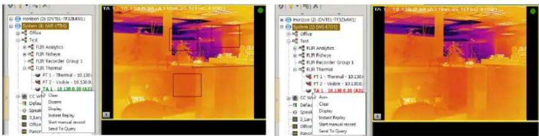
Analytics Armed - Disarm using Context Menu
Analytics Disarmed - Arm using Context Menu
6.4.1.4 PTZ Settings
The PTZ Tab provides control over all the Pan Tilt Zoom functions of applicable cameras.
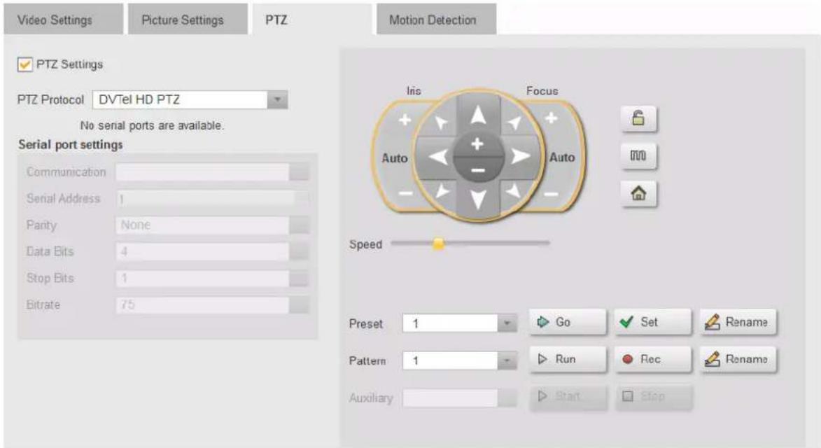
PTZ Settings
On Discovery, if the camera is recognized by the system as a supported PTZ camera, then the following fields are all set to the Camera's correct default settings.
In the PTZ configuration page of a unit with a motorized lens, a dedicated motorized lens driver should appear under "PTZ Protocol" and the following buttons will be enabled: zoom in/out, focus, iris, auxiliary, lock and menu.
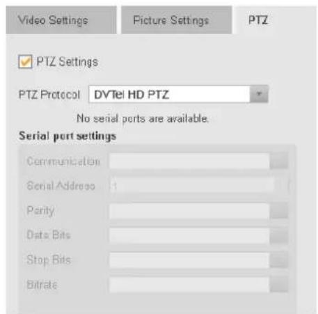
The following fields are shown:
PTZ Settings Check-box
PTZ Protocol
Serial Port Settings
Communication
Serial Address
Parity
Data Bits
Stop bits
Bitrate
Caution: The user should only use these fields when the camera's PTZ functions are controlled through a Serial Port interface (as with an analog PTZ interfaced through an encoder).
Drop-downs indicate where other parameters may be selected. Only values that are valid for the selected parameter are shown. Where parameters are disabled (grayed out) this indicates that no other choices are available.
PTZ Control
The PTZ Control panel allows the user to set up the PTZ Camera's orientation and field of view, store different combinations as 'Presets', set up automatic 'Patterns', and run the Auxiliary mode.
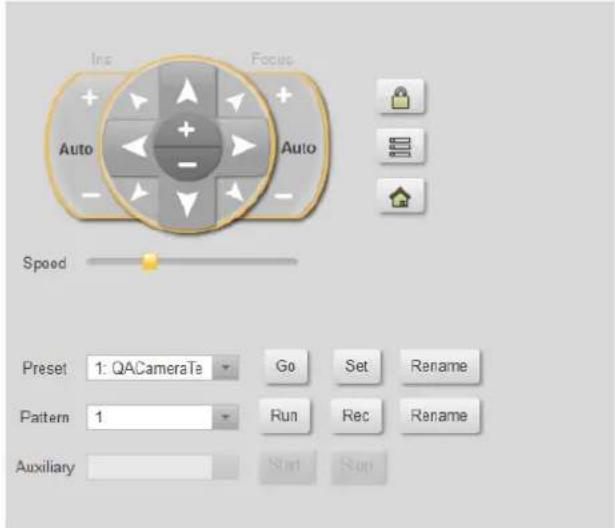
PTZ Control buttons
The PTZ Controls allow the following functions, while in PTZ Control Mode (i.e. the 'Menu' button is not pressed.)
| Field | Normal Mode('Menu' not selected) |
| Iris | |
| + | Opens the Camera Iris |
| Auto | Activates Camera's Auto Iris |
| - | Closes Camera 's Iris |
| Direction Arrows | Moves Camera in the indicated direction |
| + | Zoom in |
| - | Zoom Out |
| Focus | |
| + | Focus further |
| Auto | Activates Camera's Auto Focus |
| - | Focus nearer |
| Lock (toggle) | Locks the camera - other users cannot operate the PTZ functions |
| Home | Sends the Camera to its Home position |
Speed - Sets the speed of movement when the Direction arrows are selected by the mouse
Preset Drop-down - The Camera can be set to defined orientations called Presets. Select a Preset in the drop-down for the following functions:
Go - Move the camera to the preset orientation
Set - after moving the camera with the direction arrows and zoom controls, clicking on Set will store the current orientation as the current preset value.
Rename - Allows a name to be defined for the current Preset.
Pattern Drop-down - The camera can store a set of movements as a Pattern, which can be invoked when required. Select a Pattern in the drop-down for the following functions:
Run - When a Pattern has been defined, clicking on Run will cause the Pattern to be carried out.
Rec - Clicking on Rec starts the recording of a pattern.
(The Rec button changes to Stop.)
The Preview window indicates how much of the camera's Record buffer is used while the recording is being made.
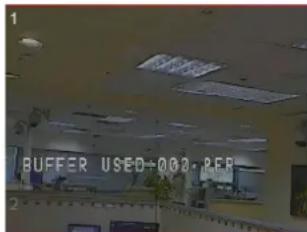
The speed, arrow and zoom controls can be used to create a Pattern.
Clicking on Stop ends the recording of the pattern.
Rename - allows the pattern to be named.
Auxiliary Drop-down - Allows selection of Auxiliary functions where installed (e.g. Wipers, Heaters)
Start - Start the selected auxiliary
Stop- Stop the selected auxiliary
PTZ Menu Mode
When the Menu button is pressed, the PTZ's internal menu is displayed in the Preview window.
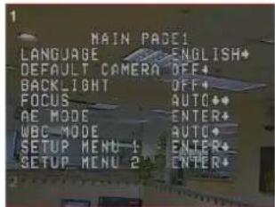
The Controls below are activated for controlling the Menu.
All other buttons and fields in the PTZ Control panel are disabled.
Menu Mode
('Menu' Selected)
Direction Arrows
Up and Down arrows allow navigation through the menu items
Left and Right buttons allow selection of individual values
Select - activates the selected Menu item
Back - Returns to the previous Menu selection
Saving your Settings
Select the required settings, and then click Apply.
6.4.1.5 Motion Detection Settings
Motion Detection Settings
The Motion Detection Settings area lists any zones that are already defined, and allows the user to set new detection zones and change the detection parameters if necessary.
After making any change to the Motion Detection zones or settings, click on Apply to make the change, or Undo to revert to the previous settings.
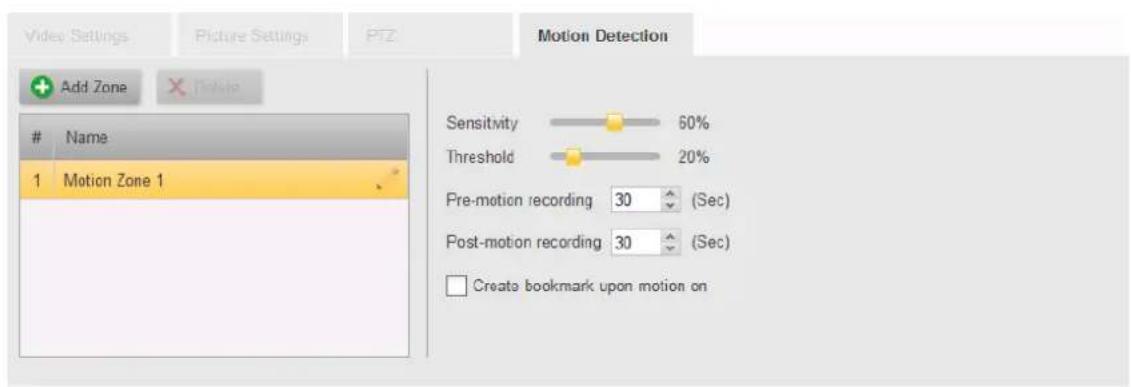
Motion Detection Zones
By default, Motion Detection Zone 1 defines the full picture area.
Editing a Motion Detection Zone
Any Motion Detection Zones that are defined for this camera will be indicated by numbered blocks in the Preview Window.
Click on the zone in the list to select it. The corresponding zone will be highlighted with a red outline in the Preview window.
The sides of the zone can be changed by hovering the mouse over the edge to get the double-arrow symbol, and the edge can then be dragged larger or smaller.
Hovering the mouse inside the zone will give a four-headed arrow, and then whole zone can then be dragged to a different position.
Adding a Motion Detection Zone
Clicking on the Add Zone button adds a new entry to the list of Motion Detection Zones, and indicates the area covered with a corresponding number and a shaded block outlined in red showing the extents of the zone.
You can edit the name given to the zone by clicking on the name, typing the new description, and clicking Apply.
Deleting a Motion Detection Zone
Click on the zone to be deleted to select it, and then click on the Delete button. You will be asked to confirm that you want to delete the zone.
Note. There must always be at least one Motion Detection zone defined.
Changing Motion Detection Settings
Sensitivity, Threshold - Default settings are assigned by the system when the camera is discovered. These should generally not be altered.
Pre - and Post- Recording (Seconds) - For cameras that are set to record based on Motion Detection, the system records continuously, and when a motion detection event occurs, then a clip is created including pre-event and post-event recording as defined by these parameters.
Create Bookmark upon motion on - Check this box if bookmarks are required for all motion events.
Saving your Settings
Select the required settings, and then click Apply.
6.4.1.6 Analytics Settings
The Analytics Tab allows the user to set up Intrusion Zones, virtual Tripwires and Masking Areas to be monitored by the Analytics capability of the camera.
For information about cameras that support Basic Analytics (Ariel Gen III, CF-6308, etc) see Basic Analytics
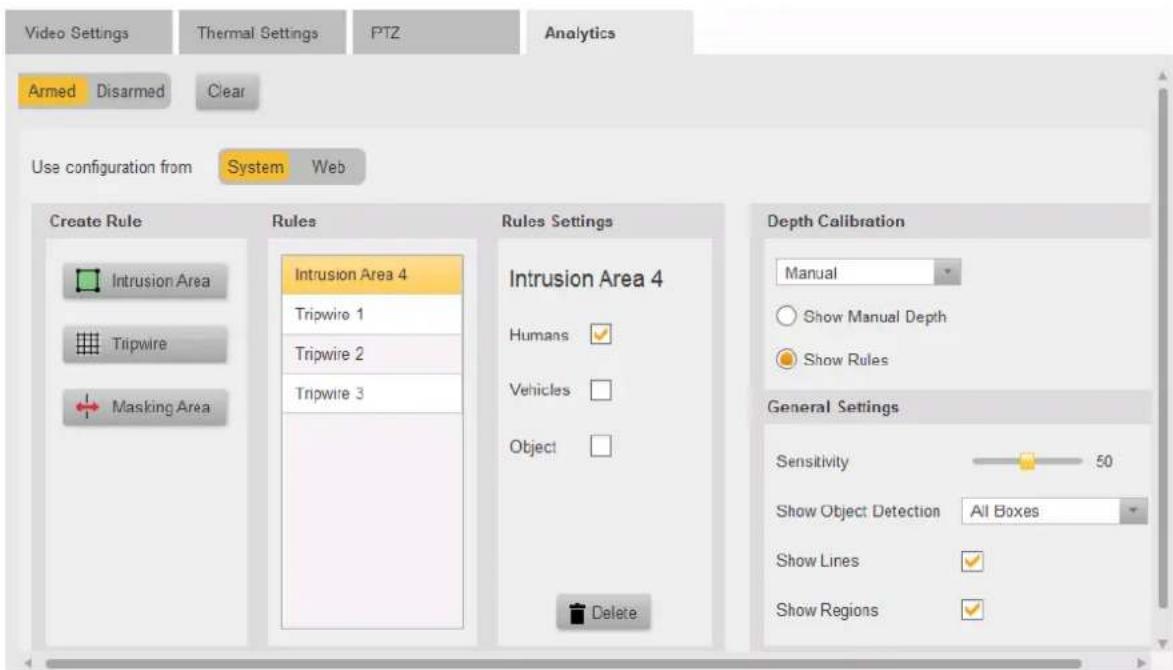
The following facilities are available:
Analytics Status
The user can set the status of the Analytics in the camera (Just as this can be done from the Control Center using the Context Menu)
Armed/Disarmed
Change the status of the Analytics.
Clear
Clear all Analytics data, events, alarms (not Settings).
Configuration Source
Analytics settings created and stored in the system are accessed when this switch is set to System. When set to System, the parameter fields are enabled, and the user can define or change settings. These settings are saved on the Horizon/Meridian system.
When set to Web, the screen will show the current settings that were created using the camera's Web interface. These cannot be edited in this page, and are therefore shown as Disabled.
Create Rule
The user can create three types of Analytic Rules
Clicking on an icon allows the user to use the mouse to create an outline of the required type in the viewing window.
Each left click adds a point to the shape. Right-clicking completes the shape. (For Intrusion Areas and Masking Areas, which are closed shapes, this is is done by connecting the last drawn point to the first.)
The completed shape is shown as a shaded area and given the next available name for that type of rule. (The camera supports up to 4 Rules of each type.).
The Masking Area Rules are always shown at the end of the list.
The user selects a rule in the Rules column, and then the characteristics of each individual rule can be set in this Rules Settings column.
A selected rule may be deleted by clicking the trash icon.
Icon
Type
Rule Description/Rule Setting

Intrusion Area
The boundary of the Intrusion area reacts to anything crossing it in either direction.
The rule may be given one or more 'classified types' (Human, Vehicle, Object) to use as a filter.
The camera will attempt react only to the selected classified types based on size.

Tripwire
In addition to the criteria above, the user can select a 'direction' to monitor.
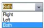

Masking Area
Masking areas are used to define areas that should be excluded from the analytics.
Depth Calibration Tab
- AutomThe Cameras determines the depth of the Relearn - Clicking the relearn button atic scene clears the previous Depth Calibration
- ManuaAllows the user to create a calibration plan and runs it again (Can take several minutes) using the mouse
- Disabl No Depth Calibration is used ed
General Settings Tab
This tab allows the user to set how the Analytics will be displayed when the camera is viewed.
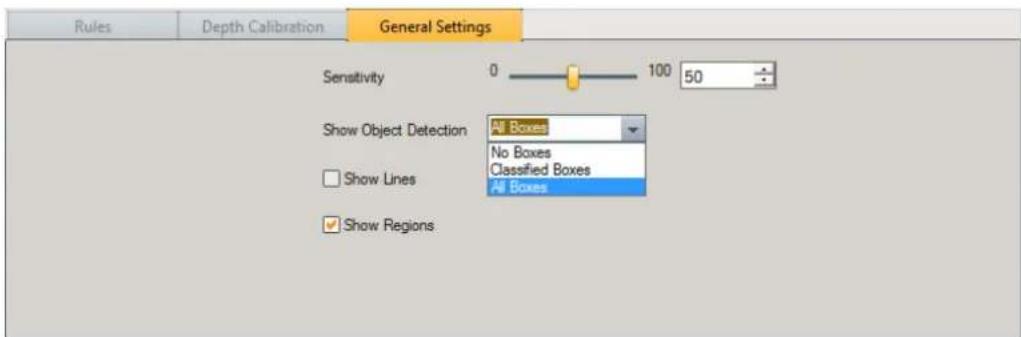
Show Object Detection
* No boxes: doesn't show a bounding box around moving targets, even if they trigger an event
* Classified boxes: shows a black bounding box around targets that have been classified, for example Human. When it triggers an event it will change to white
* All boxes: shows a black bounding box around all moving targets, it changes to white when it triggers an event
Show Lines:
When selected it will show tracking lines, when not selected it does not.
Show regions:
When selected, draws regions in black (when a region or tripwire is active it changes to white)
When not selected, shows no regions
As a general recommendation, we suggest enabling drawing Regions and Classified Boxes.
Saving your Settings
Select the required settings, and then click Apply.
6.4.1.6.1 Basic Analytics
Certain Models of FLIR cameras come with a 'Basic Analytic' feature which allows those cameras to detect analytic events and trigger actions as a result.
The analytic feature uses the same functionality that is used for motion detection and can therefore only support the use of one of these features at a time. I
There are several scenarios which will be effected by this behavior.
- Selecting "Motion recording" from the wizard while some cameras have analytics rules enabled
- Enabling analytics with a configured motion zone
- Setting a new motion zone while analytics are enabled
Supported Models:
CF-6308-00-0, CM-6308-P1-I, CM-3304-XX, CM-3308-XX, CB-3304-XX, CB-3308-XX
Selecting "Motion Recording" from the Wizard:
Setting a motion zone on a camera with enabled analytics rules (set via the camera web page) will disable the analytics rule. Therefore, if a new system is being configured with cameras that have Basic Analytics rules configured and enabled, and the Administrator selects "motion recording" from the wizard, the system will set those cameras to recording "Off" by default so to not disable their analytics configuration with a motion zone.
The user can then choose to change those settings from Admin Center after the Wizard is complete.
These cameras will NOT have the usual default motion zone configured on all other cameras. If the user choose to change recording mode to "motion" they will be prompted with the following message:
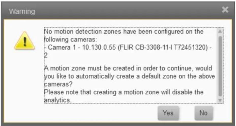
Analytics Tab:
Analytics are configured via the cameras webpage, however, there is a basic user interface for enabling/disabling and arming/disarming a camera that supports basic analytics.
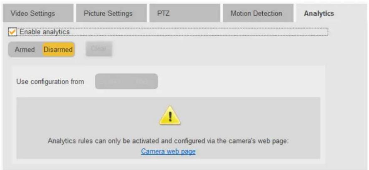
If a motion zone is configured and the user attempts to Enable Analytics, they will be prompted by the following warning:
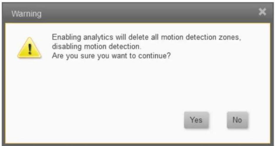
By clicking 'Yes' the motion zone will be disabled immediately (prior to saving) and the Analytics will be enabled upon saving.
By clicking 'No' the dialog box will close and no changes will have been made
If no motion zone is configured, the analytics rule will be enabled and no warning will be shown
Note:
Prior to enabling a rule from Admin Center, the analytics rule has to be configured via the web page.
Motion Tab:
If the camera's analytics are enabled and the user attempts to configure a motion zone, the following message will appear:

By clicking 'Yes' the analytic rule from the camera will be disabled, and the user will continue with their motion detection configuration
By clicking 'No' the dialog box will close and no changes will have been made
If no analytic rule is enabled on the device, the motion detection settings will remain as normal and no warning will be shown
Note: Changing Analytics or motion detection configurations using the camera's web page without deleting the settings from the VMS, may result in those changes being discarded when returning to the VMS.
7 Users Screens
Users are managed using the following screens
Users - this screen lists all the Users who are registered in the system and allows users to be edited. New Users are added using the Add Users screen.
User Groups - this screen shows the 3 default User group definitions, and any groups others added, using the Add User Group screen.
7.1 Users
This screen lists all the Users who are registered in the system, allows users to be edited, or added using the Add Users screen.
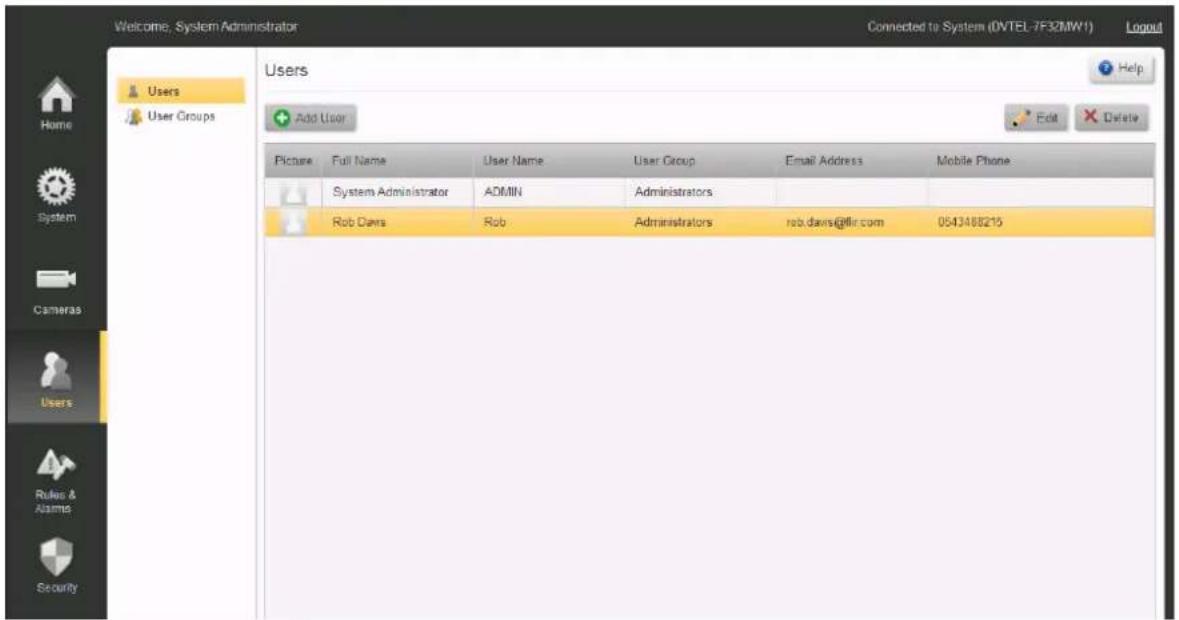
Edit a User
- Select a User by clicking an entry in the User screen.
- Click on the Edit button. The Edit User screen opens, with the selected User displayed.
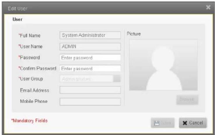
- Edit the information as required.
- Click Save to return to the User screen.
Add User
- Click Add User in the User screen. The Add User window opens.
- Add the User information.
Note: Take care to complete all mandatory fields as indicated (*). - Click Save to return to the User screen.
Delete a User
- Select a User by clicking an entry in the User screen.
- Click on the Delete button. You will be asked to confirm that you want to delete the user.
7.2 User Groups
This screen shows the 3 default User group definitions, and allows more User Groups to be defined using the Add User Group screen.
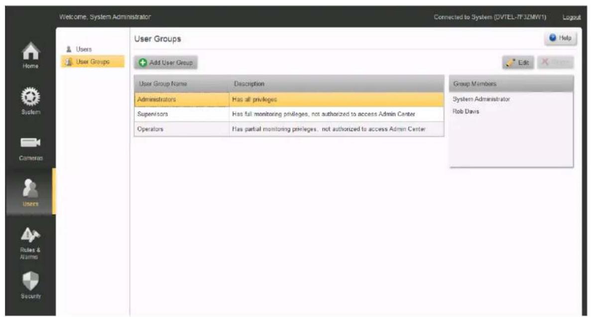
Edit User Group
- Click on the User Group to be edited in the User Group screen.
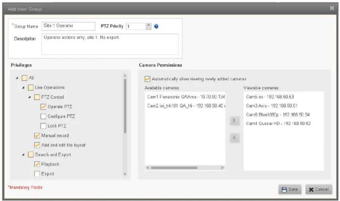
Note: The settings for the default User Groups can be displayed using the Edit button, but they are fixed - they can not be edited. (Administrators, Supervisors, Operators)
- Edit the required information.
- Click the Save button 📋 Save to Save and return to the User Groups screen.
Add User Group
- Click the Add User Group button in the User Group screen. The Add User Group window opens.
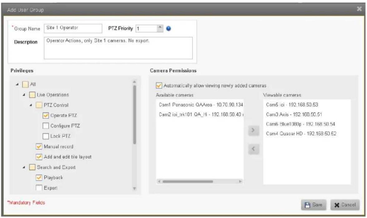
- Add the User Group information.
Note: Take care to complete all mandatory fields as indicated (*).
- Click Save to return to the User Group screen.
Delete User Group
-
Select a User Group by clicking an entry in the User Group screen.
-
Click on the Delete button. You will be asked to confirm that you want to delete the user.
Note: You cannot delete a User Group if it still has members. Before trying to delete a User Group, make sure you have transferred all Users in that group to alternative User Groups.
8 Rules and Alarms Screens
Alarms are definitions of how the system should respond to Events. Alarms can trigger live video and/or recording displays on Control Center consoles, and Alert messages to be sent to associated individual users and/or user groups. These messages must be responded to and 'cleared' by the recipients.
Rules are definitions of what Events can be recognized by the system, and how the system must respond - by raising Alarms, changing the state of switches, sending messages, etc.
Alarms define what video information must be brought to a user's attention. The Alarms screen lists all the defined alarms, and additional alarms are defined using the Add Alarm screen.
8.1 Alarms
Alarms define what video information must be brought to a user's attention. The Alarms screen lists all the defined alarms. Additional alarms are defined using the Add Alarm screen.
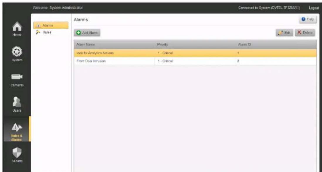
Rules and Alarms/Alarms
To add a new Alarm
- Click Add Alarm to add a new alarm to the system.
The Add Alarm dialog is presented.
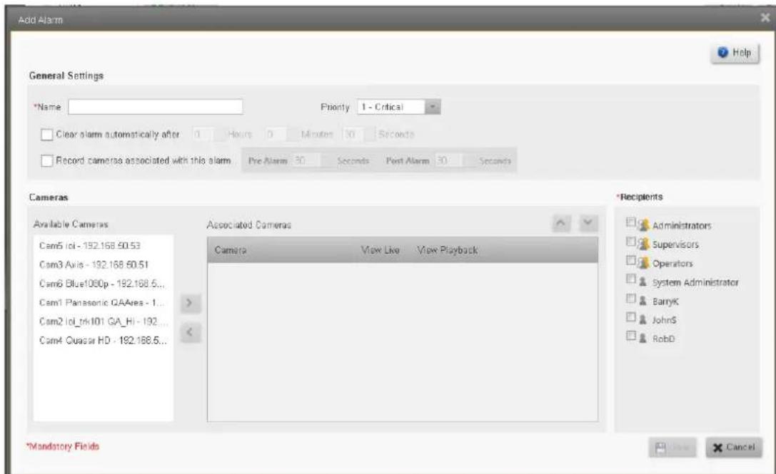
Add Alarm dialog box
- Fill in the required fields.
General Settings
Provide a Name to the alarm and set its priority (Critical, High, Medium, Low or Very Low).
Select whether the alarm should be automatically cleared or not.
If Yes, also set the time for the system to wait before automatically clearing the alarm (Hrs, Mins, Secs, range 1 sec - 24Hrs.)
Selecting 'Record cameras associated with this alarm' will create a recorded clip for all the cameras which are associated with this alarm.
The clip duration will be for the selected number of seconds before and after the trigger event.
Cameras - Table showing all 'Attached' Cameras, and which are 'Associated' with this Alarm
Select camera/s that will be associated with the alarm by clicking on them in 'Available' column, and clicking the arrow to move them to the 'Associated' column.
(Deselect cameras by clicking them in the 'Associated' column and clicking the reverse arrow)
For the selected cameras, you can choose whether live video will be displayed ('View Live', selected by default) and/or playback ('View Playback') will be displayed.
For playbacks, the time range should be specified (Pre- and Post-alarm).
Recipients
Select users and/or user groups who will receive the alarm when it is triggered.
Note: User groups (icon) are displayed in bold type
Users (icon) are displayed in regular type
When all required fields have been entered, click Save. The system will return to the 'Alarm' screen, and the new/changed Alarms will appear in the list of Alarms.
To Edit an Alarm
From the Alarms screen, select an alarm and click Edit, or double-click on the alarm.
The Edit Alarm dialog box will open showing the information for the selected alarm. Make the required changes and click Save.
To Delete an Alarm
From the Alarms screen, select an alarm and click Delete.
You will be asked to confirm that you want to remove the alarm.
8.2 Rules
Rules are definitions of what Events can be recognized by the system, and how the system must respond - by raising Alarms, changing the state of switches, sending messages, etc.
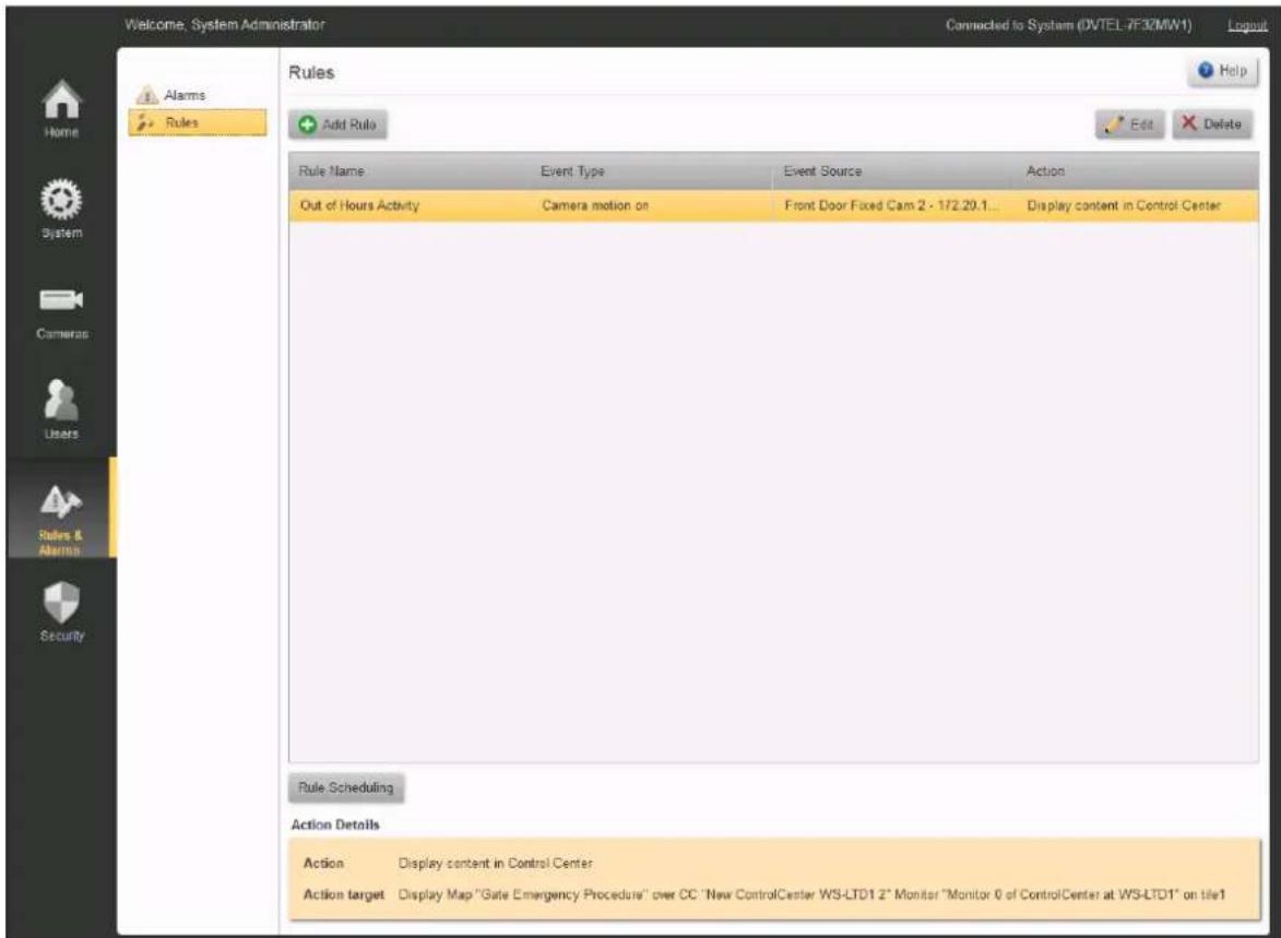
Rules and Alarms/Rules
The Rule screen lists all Rules that are defined in the system.
Select a Rule by clicking it with the mouse, and a summary of that rule is shown in the bottom of the screen.
For more information: Add a Rule Schedule a Rule
Add a Rule
- Click Add Rule in the Rules screen. The Add Rule window opens.
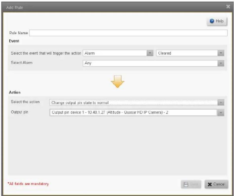
- Add the Rule information. The fields structure and contents varies depending on the Event Type and Action required. (See Events Types, below).
Note: Take care to complete all fields.
- Click Save to return to the Rules screen.
Schedule a Rule
- Once a Rule is defined, click on the Rules Scheduling button to open the Rules Scheduling screen.
By default, the schedule will be set to Always.
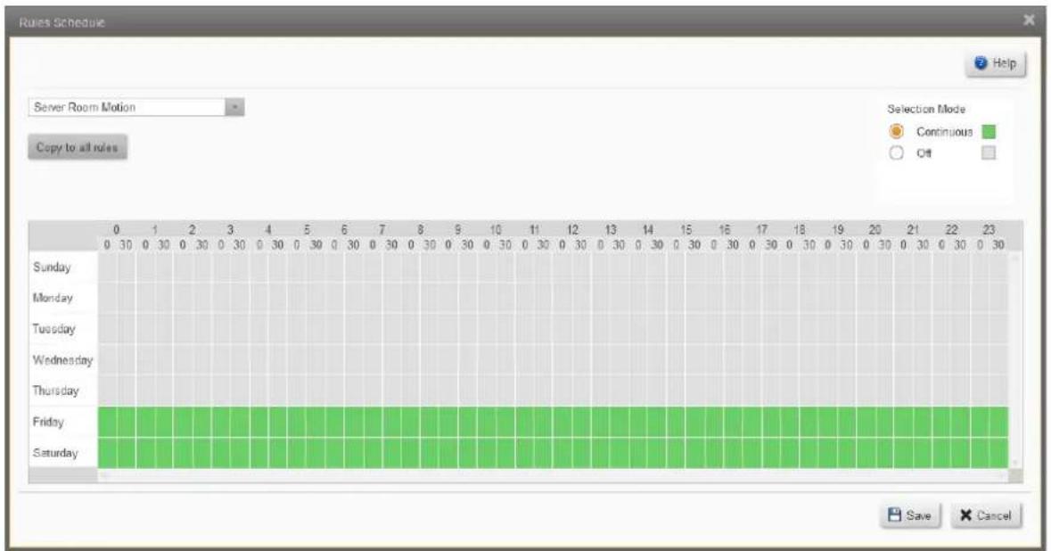
-
In the Selection Mode panel, select Continuous or None, and use the mouse to click-and-drag that selection for the required hours/days.
-
When complete, click Save to return to the Rules screen.
Delete a Rule
From the Rules screen, select a rule and click the Delete button ✗ Delete.
You will be asked to confirm that you want to delete the Rule.
Event types (Sources)
Event Type
Alarm
Camera
Input Pin
Output Pin
User
Storage
Time Trigger
Analytics
Events that are Time Triggered
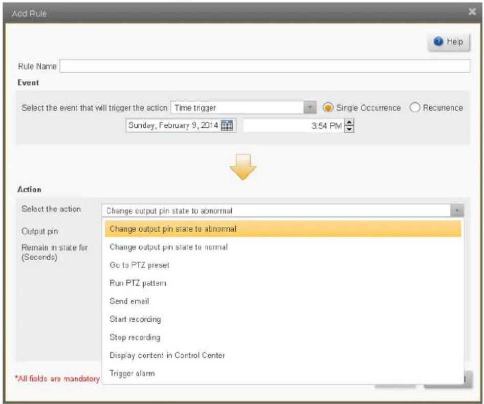
Events that are Triggered by Camera Analytics
The Analytics capabilities of ioi cameras are integrated into the Horizon/Meridian system. For these to be activated, Analytics rules must be defined through the ioi cameras' web pages, and the camera/s must be set to Armed (using the Control Center Context Menu).
9 Security Screens
The Security Screen has the following tabs:
Edge Devices (Security)
Password Policy (Security)
Settings (Security)
9.1 Edge Devices (Security)
The Edge Devices Security screen allows the user to view and modify the security settings for each of the connected devices.
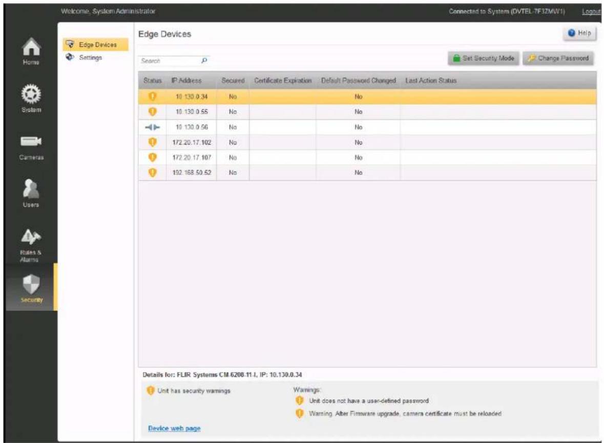
Security Action Buttons

Set Security Mode

Set Certificate

Change Password
Click here to open/close notes on Security Action Buttons
Each of these Security actions can be applied to one or more entries in the table. The actions are only enabled if they are available for the device or devices selected. i.e. If more than one entry
in the table is selected, only actions that are available for all selected devices will be enabled.
- When the user has Quasar Gen II and/or IOI-HD units, the following warning message will always be displayed:
Warning. After Firmware upgrade, camera certificate must be reloaded.
- When using Change Password on PTZ Cameras:

The Change Password functionality interrupts an open PTZ session, and can affect PTZ functionality.
Admin Center operators who wish to change password on PTZ cameras should follow these steps:
-
Go to Edge Security page, and change the password
-
Go to the Camera/PTZ Configuration page (shown here).
-
Carefully note which PTZ Driver is in use for the camera (circled).
-
Disable PTZ Settings (Uncheck)
-
Save the change
-
Re-enable PTZ Settings (Check), using the driver that was in use (Choose from the drop-down menu).
-
Save the change ☐
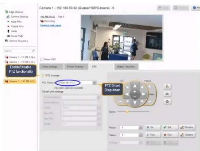
Search Box
The Search Box will filter the list of displayed devices by any information entered in this field.
Device Security Settings
The table shows the following fields:
Status:
- Icons indicate the security status of the device:
Icon Description
Unit connection is secured, but does not have trusted certificate
Unit is fully secured (Secured connection and trusted certificate)
Unit has security warning (see list below)
Unit is unsecured
Unit is blocked
Unit is inaccessible
IP Address:
Secured: Yes/No
Date of Certificate Expiration
Default Password changed : Yes/No - this highlights for the user any devices still using their original password.

It is STRONGLY recommended that these passwords be changed.
Last Action Status: Allows the user to see if an action was successfully completed.
Selected Device
The highlighted line shows which device/s in the table is/are currently selected.
Selected Device ID
Where a single device is selected, its Make, Model and IP address are displayed.
Device Security Warnings
Any warnings that apply to the selected device/s are shown.
9.2 Password Policy (Security)
Password Policy
This panel allows you to create rules regarding passwords across the system.
Settings include the following:
Setting
Minimum password
Description
When set to a value other than 0, enforces a password policy that new passwords must be greater than or equal in length to the value entered.
| Setting | Description |
| length | |
| Minimum lowercase characters | When set to a value other than 0, enforces a password policy that new passwords must contain a greater than or equal number of lowercase alpha characters than the value entered. |
| Minimum uppercase characters | When set to a value other than 0, enforces a password policy that new passwords must contain a greater than or equal number of uppercase alpha characters than the value entered. |
| Minimum numeric characters | When set to a value other than 0, enforces a password policy that new passwords must contain a greater than or equal number of numeric characters than the value entered. |
| Minimum non-alphanumeric characters | When set to a value other than 0, enforces a password policy that new passwords must contain a greater than or equal number of non-alphanumeric characters than the value entered. |
| Prohibited Passwords | This is a password disallow list that can be added to include invalid passwords. Forbidden passwords can be listed here to prevent users from using them if they are considered to pose a security risk, to be too common, or known to be exposed and no longer secure. |
9.3 Settings (Security)
This screen is divided into two sections;
○ Establish and enforce TLS Security Policy for Edge Devices,
○ Enable TLS Security for Web Client connections.
1. TLS Security Policy for Edge Devices
Click to show/hide the list of currently-supported facilities
Establishing and applying these facilities requires support in the system and from the edge devices themselves. The table below shows the current facilities supported.
| Product Type | Discovery method | TLS support | Confirm User-set Password | Change Password |
| FLIR cameras | FLIR Plug-in | Yes* | Yes | Yes** |
| Arecont, Axis, Bosch, Panasonic, Pelco, Sony | Proprietary plugin | No* | Yes | No |
| ONVIF-compatible cameras | ONVIF plug-in | Yes*** | No | Yes |
Notes:
*TLS connection can be established if supported by the unit as well as the VMS
** Changing password is supported for: FLIR core cameras, Quasar Gen II cameras, Ariel cameras and ioi HD cameras
*** Assuming the camera supports TLS
In future versions, as the capabilities of edge devices are enhanced, and as new device plug-ins are developed, this table will be updated.
TLS for Edge Devices – Choosing the options
The user sets under what conditions Edge Devices may communicate with the system.
Terms used here:
Secured Connection - Communication uses HTTPS and encryption to ensure integrity of messages and guard against malicious users.
Self-signed - Certificate is generated by the camera (or unit), rather than by a third-party Trusted Certificate Authority

Before enabling 'Use secured edge connections'
Certificates must be loaded into the cameras BEFORE enabling this option.
- Use the cameras' web pages to check if the target camera/s have an Enable/disable SSL option, and if so, ensure that is it enabled (e.g. Ariel Gen 2)
- Use the web page to upload certificates or generate self-signed certificates.
- If you use the Edge Device Security screen option 'Generate Self-signed certificate', please note that this is not supported by all manufacturers.
- Once certificates have been loaded, you can check that they are correctly set up by accessing the camera's web page through https.
Parameter
Use secured edge connection if available:
- Connecting new units
Comments
IMPORTANT: APPLIES UNITS IN THE CASES SHOWN - Other Units already in the system are not affected.
- If this option is enabled the Archiver will try to establish a secured connection with the camera. If it succeeds then all the communication with the camera will be encrypted.
Parameter
- Rediscovering existing units
- Performing firmware updates
Comments
- Discover using FLIR Plug-in or ONVIF method.
- Units must support HTTPS and have certificate already loaded, or have already created their own self-signed certificate.
Block
communications for devices using unsecured connection, but allow user to secure them
APPLIES TO ALL UNITS.
Archiver will block all communication from units except those actions that are required in order to set up secured connections. (More strict)
Block
communications for devices using untrusted certificates, but allow user to replace them
APPLIES TO ALL UNITS.
Archiver will block all communication from units except those actions that are required in order to replace the certificates. (Most strict)
Click to show/hide Notes on setting Security Policy

Note:
- When activating these rules, keep in mind that 'Use secured edge connection' applies only to new edge devices that are being discovered, Rediscovering units, and updating firmware on units – when reconnecting to devices already in the system, without rediscovering, this is not enforced.
- The two 'block devices' rules are always enforced – devices that do not meet the criteria, including those that are already connected, will be blocked.
- When changing the 2nd and third parameters (Block units with unsecured connection or Block units with untrusted connections), the units are reinitialized by the Archiver, and there may be a delay before the units become accessible again. Users should allow time for units to become available before continuing.
- When Changing passwords, special care must be taken on PTZ units. (See When using Change Password on PTZ Cameras)
- When Updating Firmware on Quasar Gen II and IOI_HD units - If Secure communications are enforced (Certificates in use), then operators must reload certificates on the units after the firmware upgrade.
2. IP Security for connections from Web Clients
The IP Security settings allow the user to activate or deactivate Transport Layer Security (TLS) which encrypts communications between the Horizon/Meridian and Web Clients.
Caution:
These parameters should be set up in consultation with the User's IT Department
Preparing to set up TLS
The following steps must be completed before activating TLS.
-
In order to use this facility, the User's IT department must arrange for a suitable TLS Certificate to be accessible to the system.
-
The system is set up to use default port settings for this feature. The user should verify with the IT department that these ports are available. See IT Setup / Secured Video Transmission for External Connection
Setting up TLS
The IP Security panel initially shows two buttons.
IP Security
Load TLS Certificate
Remove TLS Certificate
Only the 'Load TLS Certificate' button is enabled.
Clicking on this button opens an Explorer window where the user can select a TLS Certificate to be used.
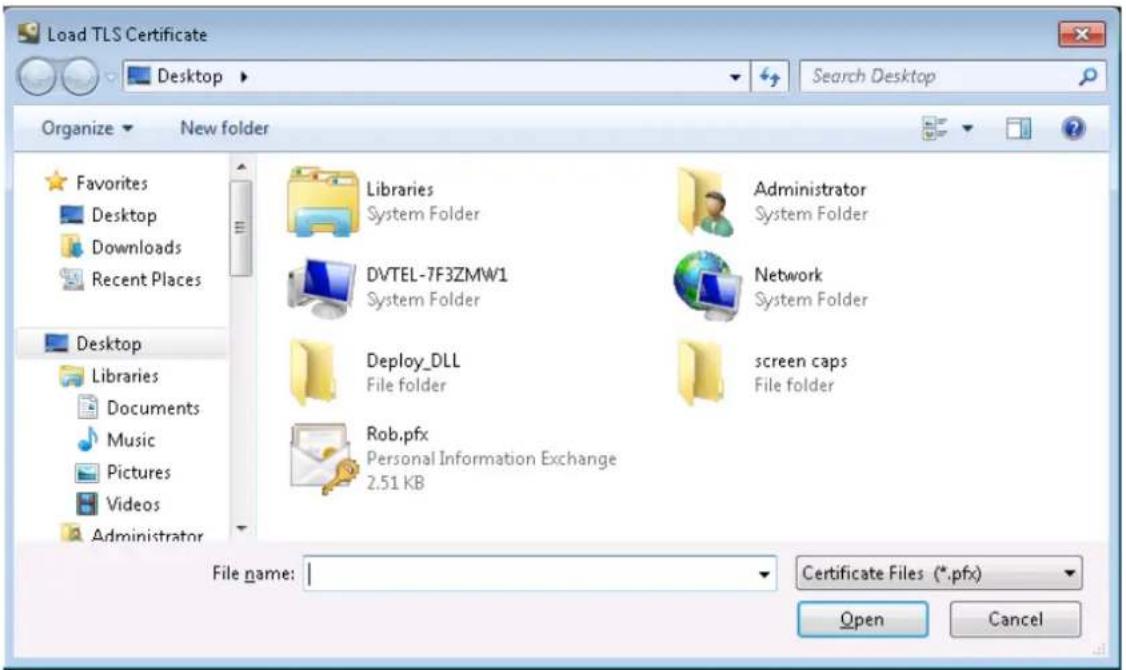
Select the .pfx file (that was previously acquired by your IT department), and click Open.
You will be asked for the Password associated with this Certificate.
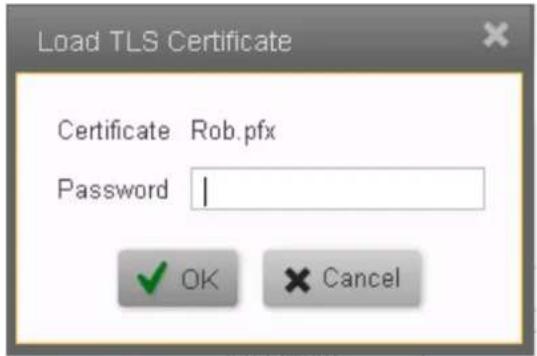
When a valid password has been entered, the system returns to the main parameter screen, and this now shows the options to Replace or Remove the TLS Certificate, and the name of the issuer of the Certificate.

The display returns to the System Parameter screen. The user must Save the changes.
Once the changes have been saved, the system will restart Web Client connections, and all subsequent communications with Web Clients will be encrypted. The https connection and secure icon show in Web Client address bars:
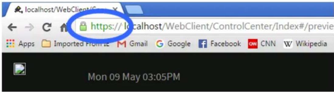
Replacing or Removing the TLS Certificate
Once a Certificate is in use, the user is shown these options.
IP Security
Replace TLS Certificate
Remove TLS Certificate
Issuer: WS-LTD1.dvtel.com
Expiration Date: 05/08/2017 02:00:00
The Replace option may only be used when an alternative Certificate is available.
The Remove option results in TLS encryption being discontinued, and further WebClient traffic is in the clear.
The user must confirm this action before it is carried out.
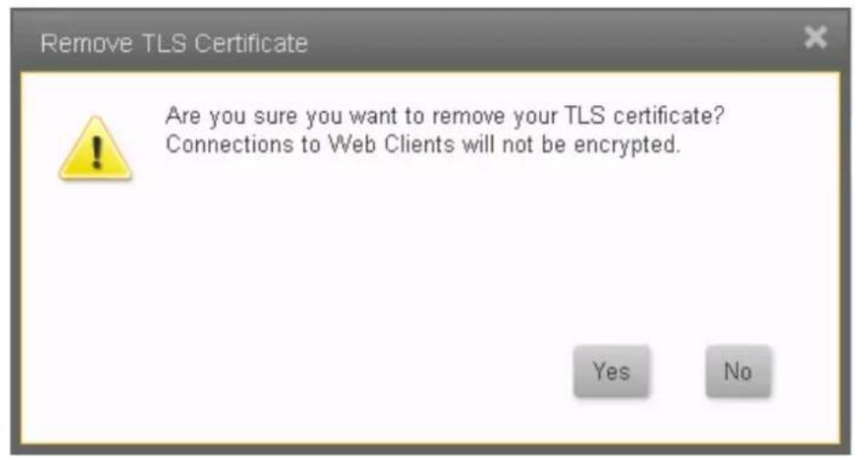
10 About this File
Welcome to the United VMS 9.2.1 Horizon/Meridian Admin Center Help File.
Note: Changes to this file were last introduced after Application Build No: 3333
Summary of latest changes:
| Change | Date Changed | Summary | Links |
| Basic Analytics | Sep 2018 | Added description of basic analytics and behavior with motion detection | Basic Analytics |
| Login Screen | Mar 2018 | The user can choose between entering a new system/IP to connect to or connect to a previously-entered server name/IP | Login Screen |
| Security Screens | Sept 2017 | The Horizon/Meridian system was upgraded to provide Transport Level Security on connections to Edge Devices. Note: This change also required all Help screenshots showing the Sidebar to be updated. | Security Screens, Edge Devices (Security), Settings (Security) |
| ,Web Client Security | Sept 2017 | The Web Client Security Tab was moved from the IT Setup screen to the Security Settings screen | IT Set, Settings (Security) up |
| Reports | Sept 2017 | Note added to Reports screen of where to find Adobe License information if required. | Reports |
| Maps | Sept 2017 | Help information about Maps was updated. | Maps |
| Analytics Tab | Mar 2017 | A new tab was introduced allowing the user to set up Analytics rules through the Horizon/Meridian system, rather than through a Web interface | Analytics Settings |
| Settings Tabs | Mar 2017 | With the addition of an Analytics Tab, the display of all Settings Tabs was re-organized. | Camera - Detailed Settings Tabs for different Camera Capabilities |
| Web Client | Oct 2016 | List compatible browsers | |
| Thermal Analytics | Oct 2016 | Using ioi Thermal Analytics | Thermal Analytics |
| Thermal Cameras | Oct 2016 | Details on the Thermal Settings Tab | Thermal Settings |
| Panoramic cameras | June 2016 | Additional information for setup of Quasar Gen2, Sentry panoramic cameras | Camera - Detailed Settings for Motion Detection, Video Picture and PTZ |
| FLIR Recorder Support | June 2016 | Support for FLIR DVR recorders and their attached cameras was introduced in this upgrade. Because attached FLIR DVRs show as standard devices, no change was made to the Help file.Note: Video recorded on the Recorders is viewable as from normal cameras, but recordings are not transferred to the main system.Details about accessing video from DVR Recorders is described in the Control Center Help file. |
| File information | May 2016 | This new topic was introduced so that users (This topic) could see the file status and have a summary of relevant recent changes. |
| Transport Layer Security (TLS) | May 2016 | Transport Layer Security is available on communications between the Web Server and any connected Web Clients.The user is responsible for acquiring and installing a suitable Certificate. |
| FLIR Branding | March 2016 | The United VMS 7.0 suite was rebranded. |
Please note: This is not a formal Change Register - the list is included so that users can quickly access Topics that contain new or changed information.
File information:
Source Horizon-Meridian Admin Date Monday, November 28, 2022 file: Center User Guide complied: 9.2.1.pdf
Please note: This is a reference to the Source File for the Help system. It is not accessible from User systems.
Americas
27700 SW Parkway Avenue
Wilsonville, OR 97070
USA
6769 Hollister Avenue
Goleta, CA 93117
USA
-3-
360° Lens 51
- A -
About 89
Action Buttons 12
AGC 51
AGC ROI 51
Alarms 73
Analytics 61
Apply 12
Arming/Disarming 51
Auxiliary 51
- C -
Camera List 50
Camera Sequence 47
Camera Settings 41
Cameras Screens 33
Color Palette 51
Copy Configuration 45
- D -
Dashboard 14
DDE 51
DDE Gain 51
Depth Calibration 61
- E -
Edge Devices 34
- H -
Home Screen 4
-1-
Intrusion Area 61
- L -
Licensing 18
Logical IDs 26
Login 3
- M -
Maps 22
Masking Area 61
Motion Detection 51
Motion Detection Settings 51
Motion Detection Zones 51
-0-
Object Detection 61
- P -
panoramic 51
Pattern 51
Picture Settings 51
Preset 51
PTZ 51
PTZ Tab 51
- R -
Recording Schedule 44
Rules 76
- S -
Screen Layout 9
Server Settings 16
Settings Page 12
Sidebar 9
Site Setup 21
Storage Setup 19
System Screens 14
-T-
Thermal Analytics 51
Thermal Settings 51
Tripwire 61
- U -
User Groups 70
Users 69

Video Settings 51
- Admin Center Help File
- Horizon/Meridian
- Table of Contents
- Horizon/Meridian Video Management System
- Compatible Browsers
- Login Screen
- SSA Expiry Notification
- Home Screen
- Notes:
- 'Check for Updates' link:
- Recommended Settings
- Recommended Settings
- Camera Settings
- Users
- Security
- Create system sign-off report
- Advanced Settings
- Advanced Settings
- Rules & Alarms
- Storage Setup
- Site Setup
- Maintenance
- Applications
- Applications
- Control Center
- Web Client
- DNA - Discovery Network Assista
- Special Start-up Screens
- Summary Screen - First time system is run
- Automatic Update
- General Screen Layout
- Sidebar
- Item List
- System Item List
- Users Item list
- Security Item list
- Cameras Item List
- Rules & Alarms Item List
- Settings Page
- Action Buttons and Help Action Buttons
- Apply
- Undo All
- Help
- To open the full Help Table of Contents:
- System Screens
- Dashboard
- Icon
- Icon Description
- Dashboard - Users Panel
- Dashboard - Cameras Panel
- Dashboard - Storage Panel
- Server Settings
- System
- Network
- Mail Server Settings
- Caution:
- Misc Settings
- Licensing
- Acquiring or upgrading a license
- License Features table
- Storage Setup
- Drives Settings
- Fields accessible to the user:
- Lifespan Settings
- Site Setup
- Maps
- Add Maps Dialog
- Option
- Control Center Display
- Add Web Page Dialog
- Logical IDs
- Maintenance
- Server Logs
- Database
- To Create/modify the Schedule for database backups
- Cloud Services
- IT Setup
- Reports
- Cameras Screens
- Edge Devices
- Rescan Network
- Adding Devices Manually - See the separate topic Adding New Devices
- Replacing Devices
- Device Credentials
- Delete
- Discovery Settings
- License information
- Details for:
- Edge Devices Details:
- Input Pins
- Output Pins
- Audio
- Serial Ports
- Adding New Devices
- Camera Settings
- Selected Camera
- Preview Window
- Apply / Undo
- Table of all Attached Cameras
- Selected Camera Details
- Copy Configuration Button
- Calculated Bitrate
- No. of Streams
- Estimated Archive Lifespan
- Recording Schedule
- To Create a new Schedule:
- To Edit an exiting Schedule
- Copy Configuration
- Source
- Destination
- List of possible Camera States
- Camera Sequence
- To Add a new Camera Sequence
- To Edit a Camera Sequence
- To Delete a Camera Sequence
- Camera List
- Camera - Detailed Settings Tabs for different Camera Capabilities
- Camera Name
- The paragraphs below provide more information
- Available Tabs
- Enable Panoramic Lens Configuration
- Video Settings
- Note:
- Enable recorded stream (Click for more detail)
- Saving your Settings
- Picture Settings
- Setting up the best picture
- Other parameters
- Thermal Settings
- PTZ Settings
- PTZ Settings
- PTZ Control
- PTZ Control buttons
- PTZ Menu Mode
- Menu Mode
- ('Menu' Selected)
- Direction Arrows
- Motion Detection Settings
- Motion Detection Settings
- Name
- Motion Detection Zones
- Editing a Motion Detection Zone
- Adding a Motion Detection Zone
- Deleting a Motion Detection Zone
- Changing Motion Detection Settings
- Analytics Settings
- Analytics Status
- Armed/Disarmed
- Clear
- Configuration Source
- Create Rule
- Depth Calibration Tab
- General Settings Tab
- Show Object Detection
- Show Lines:
- Show regions:
- Basic Analytics
- Supported Models:
- Selecting "Motion Recording" from the Wizard:
- Analytics Tab:
- Motion Tab:
- Users Screens
- Users
- Edit a User
- Add User
- Delete a User
- User Groups
- Edit User Group
- Add User Group
- Delete User Group
- Rules and Alarms Screens
- Alarms
- To add a new Alarm
- General Settings
- Cameras - Table showing all 'Attached' Cameras, and which are 'Associated' with this Alarm
- Recipients
- To Edit an Alarm
- To Delete an Alarm
- Rules
- Add a Rule
- Schedule a Rule
- Delete a Rule
- Event types (Sources)
- Event Type
- Events that are Triggered by Camera Analytics
- Security Screens
- Edge Devices (Security)
- Security Action Buttons
- Search Box
- Device Security Settings
- Status:
- IP Address:
- Date of Certificate Expiration
- Selected Device
- Selected Device ID
- Device Security Warnings
- Password Policy (Security)
- Password Policy
- Settings (Security)
- TLS Security Policy for Edge Devices
- TLS for Edge Devices – Choosing the options
- Before enabling 'Use secured edge connections'
- Parameter
- Comments
- Block
- APPLIES TO ALL UNITS.
- Click to show/hide Notes on setting Security Policy
- IP Security for connections from Web Clients
- Preparing to set up TLS
- Setting up TLS
- Replacing or Removing the TLS Certificate
- IP Security
- About this File
- File information:
Brand : FLIR
Model : Meridian 9.3
Category : Uncategorized