
VH-4GW - Wi-Fi Router AIRLIVE - Free user manual and instructions
Find the device manual for free VH-4GW AIRLIVE in PDF.


| Product Type | 4G LTE Vehicle Gateway / Hotspot |
| Brand | AirLive |
| Model | VH-4GW |
| Dimensions (W x D x H) | Approx. 180 x 120 x 30 mm |
| Weight | Approx. 300 g |
| Power Input | 12V DC (vehicle power adapter included) |
| Mobile Network Support | 4G LTE (up to 150 Mbps downlink) |
| Wi-Fi Standard | 802.11 a/b/g/n/ac (dual-band 2.4 & 5 GHz) |
| Ethernet Ports | 2 x 10/100/1000 Mbps LAN (RJ-45) |
| Additional Interface | 1 x SIM card slot (standard), 1 x USB 2.0 (for storage/share) |
| VPN Support | OpenVPN, L2TP, PPTP, IPSec |
| GPS | Built-in GPS module for location tracking |
| Antenna Connectors | 2 x SMA for cellular, 2 x RP-SMA for Wi-Fi |
| Security Features | WPA2-PSK, SPI firewall, VPN pass-through, MAC filtering |
| Main Functions | Mobile internet access, Wi-Fi hotspot, routing, VPN, GPS tracking |
| Care and Cleaning | Wipe with dry cloth; keep away from liquids and extreme temperatures |
| Safety | Do not open; avoid exposure to rain or moisture; disconnect power during storms |
| Spare Parts and Repairability | No user-serviceable parts; contact support for repairs |
| General Information | Designed for use in vehicles; supports up to 32 Wi-Fi clients |
Frequently Asked Questions - VH-4GW AIRLIVE
User questions about VH-4GW AIRLIVE
0 question about this device. Answer the ones you know or ask your own.
Ask a new question about this device
Download the instructions for your Wi-Fi Router in PDF format for free! Find your manual VH-4GW - AIRLIVE and take your electronic device back in hand. On this page are published all the documents necessary for the use of your device. VH-4GW by AIRLIVE.
USER MANUAL VH-4GW AIRLIVE
4G LTE Vehicle Gateway with WiFi
User Manual
Air Live®
Powered by OvisLink Corp.
Version 1.0
This guide is written for firmware version 1.0 or later.
Copyright & Disclaimer
No part of this publication may be reproduced in any form or by any means, whether electronic, mechanical, photocopying, or recording without the written consent of OvisLink Corp.
OvisLink Corp. has made the best effort to ensure the accuracy of the information in this user's guide. However, we are not liable for the inaccuracies or errors in this guide. Please use with caution. All information is subject to change without notice
This product requires professional installation. Please do not attempt to install the device without the necessary knowledge in regards to your country's wireless regulations.
Functions and features in your product's firmware might be different due to regulations in your country.
Table of Contents
1. Introduction...... 1
1.1 Overview.... 1
1.2 Special Notice.... 1
1.3 How to Use This Guide.... 2
1.4 Firmware Upgrade and Tech Support 2
1.5 Features 2
1.6 Wireless Operation Modes.... 3
1.6.1 WDS Bridge Mode....3
1.6.2 AP Router Mode....4
2. Installing the VH-4GW 5
2.1 Before You Start.... 5
2.2 Package Content 5
2.3 Knowing your VH-4GW....6
2.4 Hardware Installation 8
2.4.1 Insert the SIM card....8
2.4.2 Connecting Power....9
2.4.3 Mount VH-4GW 10
2.5 Restore Settings to Default.... 10
3. Configuring the VH-4GW.... 11
3.1 Important Information....11
3.2 Prepare Your PC....11
3.3 Easy Setup by Web Interface.... 12
3.3.1 Wizard 13
3.4 Status 17
3.4.1 Dashboard 18
3.4.2 Networks Status 18
3.4.3 WiFi Status....20
3.4.4 LAN Client List 21
3.4.5 Firewall Status ....21
3.4.6 VPN Status....23
3.4.7 System Management Status 24
3.4.8 DDNS Status....24
3.4.9 UPNP Port Status 25
3.4.10 Statistic & Reports 25
3.4.11 GNSS 26
4. Web Management 27
4.1 Basic Network.... 29
4.1.1 WAN Setup .... 30
4.1.2 LAN and VLAN Setup 49
4.1.3 WiFi Setup 57
4.1.4 IPv6 Setup....72
4.1.5 NAT/Bridging 75
4.1.6 Routing Setup....79
4.1.7 Client/Server/Proxy....83
4.2 Advanced Network....87
4.2.1 Firewall 88
4.2.2 QoS & BWM 99
4.2.3 VPN Setup....107
4.2.4 Redundancy....128
4.2.5 System Management 129
4.2.6 Certificate....133
4.3 Application....141
4.3.1 Mobile Application 141
4.3.2 Captive Portal....148
4.3.3 Position Applications 149
4.4 System 157
4.4.1 System Related.... 158
4.4.2 Scheduling....163
4.4.3 Grouping 164
4.4.4 External Servers 168
4.4.5 MMI 169
5. VH-4GW Specifications ....170
5.1 Features ....170
5.2 Specifications ....170
6. Wireless Network Glossary....173
1
Introduction
natural_image
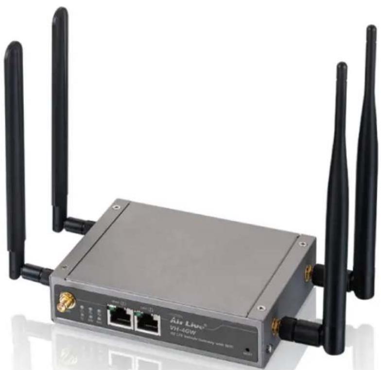
Exterior view of a Air Line® VH-4GW wireless router with two black antennas and ports (no text or symbols on the device body)1.1 Overview
The VH-4GW is a 4G LTE Vehicle Gateway with 2.4 G wireless. It can receive 3G/4G LTE signal and provide 802.11 b/g/n WiFi signal. When installed in Vehicle, it can connect the Car Power directly. It is an innovative product for IoT (Internet of Things) application.
1.2 Special Notice
This product requires professional installation. Please do not attempt to install the device without the necessary knowledge in regards to your country's wireless regulations.
Functions and features in your product's firmware might be different due to regulations in your country.
1.3 How to Use This Guide
VH-4GW is an advanced LTE Vehicle gateway with many functions. It is recommended that you read through the entire user's guide whenever possible. The user guide is divided into different chapters. You should read at least go through the first 3 chapters before attempting to install the device.
Recommended Reading
☐ Chapter 2: Installation the VH-4GW
This chapter is about hardware installation. You should read through the entire chapter.
☐ Chapter 3: Configuration the VH-4GW
This Chapter is about how to configure each function of VH-4GW
1.4 Firmware Upgrade and Tech Support
If you encounter a technical issue that cannot be resolved by information on this guide, we recommend that you visit our comprehensive website support at www.airlive.com. The tech support FAQ are frequently updated with latest information.
In addition, you might find new firmware that either increase software functions or provide bug fixes for VH-4GW. You can reach our on-line support center at the following link:
http://www.airlive.com/support/support_2.jsp
1.5 Features
● Cellular Gateway for vehicle LTE-Fi Hotspot applications
● 802.11n 2Tx2R with 3dBi detachable Antenna
- Detachable 4G antenna
● 4G/3G, WAN Load Balance
● Fully protocol stack for both IPv4 and IPv6,
- VPN supported
● Captive Portal Supported
- QoS and Bandwidth management
● SNMP, Web, and TR069 for administrator to manage system
● Power input range from 9V \~ 36Vdc for vehicle battery
1.6 Wireless Operation Modes
The VH-4GW can perform as a multi-function wireless device. Users can easily select which wireless mode they wish the VH-4GW to perform.
The VH-4GW can be configured to operate in the following wireless operation modes:
1.6.1 WDS Bridge Mode
This mode is also known as “WDS Pure MAC mode”. When configured to operate in the Wireless Distribution System (WDS) Mode, the VH-4GW provides bridging functions with remote LAN networks in the WDS system. The system will support up to total of 8 bridges in a WDS network (by daisy chain). However, each bridge can only associate with maximum of 4 other bridges in the WDS configuration. This mode is best used when you want to connect LAN networks together wirelessly (for example, between office and warehouse). If you have more than 2 AP in WDS Bridges mode, please remember to avoid duple connection to one device, otherwise the network loop can be occurred. This mode usually delivers faster performance than infrastructure mode.

flowchart
graph LR
    A["Office LAN"] -->|Wireless Signal| B["WDS Bridge"]
    B -->|Signal| C["Office LAN"]
    D["Warehouse LAN"] -->|Signal| E["WDS Bridge"]
    E -->|Signal| F["Warehouse LAN"]
1.6.2 AP Router Mode
In AP Router Mode, the VH-4GW behaves like a wireless router. Both the wireless and the PoE port of VH-4GW becomes the LAN side and 3G/4G act as the WAN . User can manage the VH-4GW through the wireless or PoE port. And if the remote management is opened, user can also get to manage VH-4GW via the WAN side.

flowchart
graph TD
    A["Client AP"] --> B["AP Router"]
    B --> C["Internet"]
    D["Laptop"] -->|Wireless Signal| B
    E["Computer"] -->|Wireless Signal| B
    B -->|Wireless Signal| C
2
Installing the VH-4GW
This section describes the hardware features and the hardware installation procedure for the VH-4GW. For software configuration, please go to chapter 3 for more details.
2.1 Before You Start
It is important to read through this section before you install the VH-4GW
The use of 3G/4G LTE, each country have its own telecom regulation for the frequency. Please consult with your country's telecom company for the correct SIM card and suitable mobile internet package.
The use of 2.4GHz spectrum, the allowed WiFi channels can be very in different country. Please consult with your country's telecom regulation first.
■ The VH-4GW is a 2.4GHz CPE device only; it cannot operate in 5GHz.
2.2 Package Content
The VH-4GW package contains the following items:
| Items | Description | Contents | Quantity |
| 1 | VH-4GW |  | 1pcs |
| 2 | Cellular Antenna |  | 2pcs |
| 3 | WiFi Antenna |  | 2pcs |
| 6 | Mounting Bracket |  | 2pcs |
| 7 | DIN-Rail Bracket |  | 1pcs |
2.3 Knowing your VH-4GW
Below are descriptions and diagrams of the product:


LED Behavior

| LED Icon | Indication | LED Color | Description |
 | Power Source | Green | Steady ON: Device is powered on by power source 1 |
 | WLAN (WiFi) Green | Steady ON: Wireless radio is enabledFlash: Data packets are transferredOFF: Wireless radio is disabled | |
 | Internet Green | Steady ON: Internet connection is establishedFlash: Data packets are transferred thru InternetOFF: Internet connection is not established | |
 | SIM Green | Steady ON: SIM card is chosen for connection | |
 | Cellular | Green | Steady ON: Cellular function is enabled |
 | GPS | Green | Steady ON: GPS function is enabled |
2.4 Hardware Installation
Please prepare a screw driver and an outdoor graded PoE Ethernet cable with adequate length according to your need.
2.4.1 Insert the SIM card
Before inserting or changing the SIM card, please power off the VH-4GW
The SIM card slots are located at the bottom side of VH-4GW. Please unscrew and remove the outer bottom over of VH-4GW and follow below instructions to insert SIM cards. After SIM cards are well placed, screw back the outer bottom cover.
Step 1:
Follow red arrow to unlock the SIM card slot.
Step 2:
Lift up SIM holder, and insert SIM card
Step 3:
Put back SIM holder, and follow red arrow to lock SIM socket.

natural_image
Close-up of a green electronic device with a red arrow pointing to a component, no visible text or symbols.
natural_image
Close-up of a green electrical connector with internal components and a red dashed circle highlighting a specific part (no text or symbols visible)
natural_image
Close-up of a green electronic component with a red arrow pointing to a small white component, mounted on a white wall (no text or symbols visible)2.4.2 Connecting Power
The VH-4GW series unit provides a 9 \~36V DC power module. An VH-4GW unit can be powered by connecting a power source to the power terminal block. . Below Figure indicates pin assignments of the power terminal block. Please connect carefully your power source. Make sure the electrodes have been plugged into the right pins according to their assignments.

natural_image
Green electrical connector with two terminals and a central port (no text or symbols visible)The power terminal block
Note :VH-4GW package includes a converter and a DC12V/2A power adapter for you to easily connect DC power adapter to this terminal block.

natural_image
Two electronic components: a black cable with wires and a black power adapter connected to its right (no text or symbols visible)The DC converter and DC 12V/2A power adapter
2.4.3 Mount VH-4GW
The VH-4GWcan be placed on a desktop, mounted on the wall or mounted on a DIN-rail. The DIN-rail bracket is not screwed on the product when out of factory. Please screw the DIN-rail bracket on the product first if necessary.
2.5 Restore Settings to Default
If you have forgotten your VH-4GW's IP address or password, you can restore your VH-4GW to the default settings by pressing on the "reset button" for more than 10 seconds. The reset button is located on button of VH-4GW.
3
Configuring the VH-4GW
In this chapter, we will explain VH-4GW's available management interfaces and how to get into them. Then, we will provide the introduction on Web Management and recommended initial settings. For detail explanations on Web Management functions, please go to Chapter 4 and 5.
3.1 Important Information
The following information will help you to get start quickly. However, we recommend you to read through the entire manual before you start. Please note the password and SSID are case sensitive.
☐ The default IP address is:192.168.123.254
Subnet Mask: 255.255.255.0
☐ The default password is: airlive
☐ The default wireless mode is :AP Router Mode
☐ After power on, please wait for 2 minutes for VH-4GW to finish boot up
3.2 Prepare Your PC
The VH-4GW can be managed remotely by a PC through either the wired or wireless network. The default IP address of the VH-4GW is 192.168.123.254 with a subnet mask of 255.255.255.0. This means the IP address of the PC should be in the range of 192.168.123.1 to 192.168.123.253.
To prepare your PC for management with the VH-4GW, please do the following:
-
Connect your PC directly to the LAN port of VH-4GW
-
Set your PC's IP address to obtain the IP automatically or manually to 192.168.123.100 (or other address in the same subnet)

You are ready now to configure the VH-4GW using your PC.
3.3 Easy Setup by Web Interface
The VH-4GW can be configured using the web interfaces:
Web Management (HTTP): You can manage your VH-4GW by simply typing its IP address in the web browser. Most functions of VH-4GW can be accessed by web management interface. We recommend using this interface for initial configurations. To begin, simply enter VH-4GW's IP address (default is 192.168.123.254) on the web browser. The default password is "airlive".
3.3.1 Wizard
Select "Wizard" for basic network setting and VPN settings in a simple way. Or you can go to "Basic Network/ Advanced Network/ Applications / System" to setup the configuration by own selection.
3.3.1.1 Configure with the Network Setup Wizard
Step 1 : Guideline
The Network setup wizard will guide you to finish some basic settings including login password, time zone, WAN interface, Ethernet LAN interface and WiFi LAN interface. One “EXIT” button at the upper-right corner of each window is provided for you to quit the setup process. Press “Next” to start the wizard.
Step 2: Change Password
Password configuration : You can change the login password of Web UI here. It's strongly recommending you to change this login password from default value. Press "Next" to continue
Step 3: Time Zone
Time Zone configuration: It will detect your time zone automatically. If the result of auto detection is not correct, you can press "Detect Again" button or select manually. Press "Next" to continue
Step 4 WAN Interface setting
WAN interface Configuration: Choose the physical interface and WAN type for Internet connection.. Press "Next" to continue
Step 4-1 : When 3G/4G is selected
Please make sure you have inserted SIM card. If not, please power off this gateway, and insert SIM card first. Then you can select "Auto-Detection" to finish dail-up profile automatically. Press "Next" to continue.
Step 4-2 : When Ethernet is selected
In Ethernet is selected as the Physical interface, there are 5 difference WAN type. Please select the correct WAN type and click Next for setting
Step 5: Ethernet LAN interface
LAN interface configuration: Change the LAN IP address and subnet mask of this gateway for the Intranet. You can keep the default setting and go to next step. Press "Next" to continue.
Step 6 WiFi LAN (2.4G)
WiFi LAN interface configuration: Change the SSID, Channel Number,
Authentication and Encryption for first virtual AP of this gateway. You will see on your PC when doing wireless network scan. It is strongly recommending to add authentication and encryption in your wireless network to prevent any unknown WiFi clients and keep transferred data secured. You can also keep the default setting and go to next step. Press “Next” to continue.
Step 7 Confirm and Apply
Check the new settings again. If all information is correct, please press "Apply" button to save new settings. Then it will take 65 seconds to restart this gateway and take new settings effective.
Step 8 Counting Down
Configuration is completed. Press "Finish" button to close Setup Wizard and browser counts down for 65 seconds and provides you with "Click here" button to reconnect to the device
3.3.1.2 Configure with the VPN setup wizard
Step 1: Guideline
The VPN setup wizard will guide you to finish profiles of IPSec, PPTP, L2TP and GRE VPN connection quickly. Press “Next” to start the wizard.
Step 2 VPN Type
Select type of VPN connection you want to create. Here you can choose IPSec, PPTP, L2TP or GRE. Press "Next" to continue.
Step 3-1: IPSec
If choosing IPSec, there are five options of tunnel scenario can be chosen. "Site to Site" is for two offices to create a VPN tunnel. "Site to Host" is for one office to access one specific server via an IPSec tunnel. "Host to Site" is for service agents in the device to access the intranet of an remote office via a tunnel. "Host to Host" is for two agent peer to create a secure tunnel for data communication. "Dynamic VPN" is for mobile users with dynamic IP address to connect to central office. For other options, please go to [Advanced Network] - [VPN] to setup. And then input the required network information and pre-shared key for VPN connection.
Step 3-2:PPTP
If choosing PPTP, there are two options of mode can be chosen. Choose "Server" if you want other PPTP clients to connect to it. Press "Next" to continue.
If choosing PPTP Client, please input tunnel name, IP/FQDN of PPTP server, user name & password, choose default gateway/remote subnet, authentication protocol and MPPE encryption option. Please make sure these settings are accepted by remote PPTP server. Otherwise, PPTP server will reject the connection. Press “Next” to continue.
If choosing PPTP Server, please choose options of authentication protocol and key length of MPPE encryption. You also need to create a set of username and password for PPTP clients. In this wizard, you only create one user account. If you want to create more user accounts, please go to [Advanced Network] - [VPN] - [PPTP] to add more users. Press “Next” to continue
Step 3-3: L2TP
If choosing L2TP, there are two options of mode can be chosen. Choose "Client" if you want this device to connect to another L2TP server. Or choose "Server" if you want other L2TP clients to connect to it.
Press "Next" to continue.
![Select VPN Type (Step-2) > VPN Type UTP Next Server < Back [ Start > Type > Configurations > Summary > Finish ] Next >](/content/2026/05/914011/images/5b7c8380b4d6ae7e70e88e8dcc15c51f0f3de82aa8a04869ca271393818ff4ac.jpg)
If choosing L2TP Client, please input tunnel name, IP/FQDN of L2TP server, user name & password, choose authentication protocol and MPPE encryption option. Please make sure these settings are accepted by remote L2TP server. Otherwise, L2TP server will reject the connection.
Press "Next" to continue.
![VM3 Configuration (Step 4) [L2TP Client] L2TP Client1 Peer INFQON User Account Default Gateway/Remote Subnet Authentication Protocol MIME Encryption L2TPClient1 148 116.82.98 Account: L2TPAccount Password: ****** Remote Subnet: 15.076.0/24 PAP CHAP MS_CHAP MS_CHAPV2 Enable < Back [ Start > Type > Configuration > Summary > Finish ] Next >](/content/2026/05/914011/images/651669380e9e13507337fb6e8033ebc2f0a4476218c8da93e0c5e0ee32fec558.jpg)
If choosing L2TP Server, please choose options of authentication protocol and key length of MPPE encryption. You also need to create a set of username and password for L2TP clients. In this wizard, you can only create one user account. If you want to create more user accounts, please go to [Advanced Network] - [VPN] - [L2TP] to add more users.
Press "Next" to continue.

Step 3-4: GRE
If choosing GRE, please input tunnel name, IP address of remote GRE peer, Key ID and choose default gateway / remote subnet. Please make sure these settings are accepted by peer GRE site. Otherwise, remote GRE peer will reject the connection.
Press "Next" to continue.
![VPN Configuration (Step-3) [GRE] [ EXIT ] • GRE Tunnel Name • Remote IP • Rcy • Default Gateway/Remote Subnet GRE #1 T40.116.82.36 1254367890 Remote Subnet 10.0.76.024 < Back { Start > Type > Configuration > Summary > Finish } Next >](/content/2026/05/914011/images/3dac4922646521ba4c4eac870fbee0768c096d3dac265b4bcb48c324522a7eac.jpg)
Step 4: Confirm and Apply
Confirm new settings. If all new settings are correct, please press "Apply" button to save these new settings and take them effective.
![[VPN Type] VPN Type GRE [VPN Settings] GRE Tunnel Name GRE #1 Remote IP 140.116.82.98 Key 1234567890 Remote Subner 10.0.70.3/24 Cancel [ Start > Type > Configuration > Summary > Finish ] Apply [EXIT]](/content/2026/05/914011/images/75a86e079b12028bc9d4d1a339606919fa444450192b055171a42afa12de2454.jpg)
3.4 Status
There are 10 kinds of system status to be shown at this window. They are Dash board, Network Status, WiFi Status, LAN Client List, Firewall Status, VPN Status, System Management Status, DDNS Status, UPnP Port Status, Statistic & Report.

3.4.1 Dashboard
In Dashboard, it shows all of the status graphically.

3.4.2 Networks Status
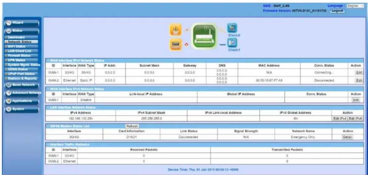
In Network Status page, you can review lots information of network status, including a connection diagram, WAN IPv4 status, WAN IPv6 status, LAN status, and 3G/4G modem status. You can also check the device time at the bottom of this page.
Connection Diagram

flowchart
graph LR
    A["3G/4G"] -->|Wireless Signal| B["Roger"]
    C["xDSL/Cable"] -->|Wireless Signal| B
    B --> D["Client:0"]
    B --> E["Client:1"]
- 3G/4G Icon: Indicates if 3G/4G and USB3G / 4G WAN connections are established or not.
- Wired Client Icon: Indicates how many Ethernet clients are connected now.
- WiFi Client Icon: Indicates how many WiFi clients are connected now.
WAN Interface IPv4 Network Status
Display WAN type, IPv4 information, MAC information, and connection status of multiple WAN interfaces in IPv4 networking. Press "Edit" button if you want to change settings.
| WAN Interface IPv4 Network Status | |||||||||
| WAN ID | Interface | WAN Type | IP Addr. | Subnet Mask | Gateway | DNS | MAC Address | Conn. Status | Actions |
| WAN-1 | 3G/4G | 3G/4G | 0.0.0.0 | 0.0.0.0 | 0.0.0.0 | 0.0.0.0,0.0.0.0 | N/A | Connecting... | Edit |
WAN Interface IPv6 Network Status
Display WAN type, IPv6 information, and connection status of multiple WAN interfaces in IPv6 networking. Press "Edit" button if you want to change settings.
LAN Interface Status
Display IPv4 and IPv6 information of local network. Press "Edit" button if you want to change settings.
| LAN Interface Status | |||||
| IPv4 Address | IPv4 Subnet Mask | IPv6 Link-Local Address | IPv6 Global Address | Actions | |
| 10.0.75.2 | 255.0.0.0 | /64 | Edit IPv4 | Edit IPv6 | |
3G/4G Modem Status
Display modem information, link status, signal strength, and network (carrier) name of 3G/4G connection.
| 3G/4G Modem Status Refresh | |||||
| Physical Interface | Card Information | Link Status | Signal Strength | Network Name | Actions |
| 3G/4G | D16Q1 | Connecting... | N/A | Detail | |
Internet Traffic Statistics
Display number of transmitted packets and received packets of each WAN interface.
| Internet Traffic Statistics | |||
| WAN ID | Physical Interface | Received Packets | Transmitted Packets |
| WAN-1 | 3G/4G | 0 | 0 |
Device Time
Display current time information of device.
Device Time: Thu, 26 Jun 2014 14:25:15 +0800
3.4.3 WiFi Status
WiFi Virtual AP List
In order to view the basic information of WiFi virtual APs, it will display operation band, virtual AP ID, WiFi activity, operation mode, SSID, channel, WiFi system, WiFi security approach and MAC address of all virtual APs on status page. Besides, there is an additional Edit command button for each virtual AP to link to the configuration page of that dedicated virtual AP.
| WiFi Virtual AP List | |||||||||
| Op. Band | VAP ID | WiFi Enable | Op. Mode | SSID | Channel | WiFi System | Auth.&Security | MAC Address | Action |
| 2.4G | VAP-1 | AP Router | JP.CDG761 | Auto | B/G/N Mixed | WPA2-PSK(TKIP) | 00:50:18:12:11:02 | Edit | |
| 2.4G | VAP-2 | AP Router | default | Auto | B/G/N Mixed | Auto(None) | 02:50:18:12:11:02 | Edit | |
| 2.4G | VAP-3 | AP Router | default | Auto | B/G/N Mixed | Auto(None) | 05:50:18:12:11:02 | Edit | |
| 2.4G | VAP-4 | AP Router | default | Auto | B/G/N Mixed | Auto(None) | 0A:50:18:12:11:02 | Edit | |
| 2.4G | VAP-5 | AP Router | default | Auto | B/G/N Mixed | Auto(None) | 0E:50:18:12:11:02 | Edit | |
| 2.4G | VAP-6 | AP Router | default | Auto | B/G/N Mixed | Auto(None) | 12:50:18:12:11:02 | Edit | |
| 2.4G | VAP-7 | AP Router | default | Auto | B/G/N Mixed | Auto(None) | 16:50:18:12:11:02 | Edit | |
| 2.4G | VAP-8 | AP Router | Guest_2.4G | Auto | B/G/N Mixed | Auto(None) | 1A:50:18:12:11:02 | Edit | |
WiFi Traffic Statistics
In order to view the traffic statistics of WiFi virtual APs, it will display operation band, virtual AP ID, the numbers of received packets and transmitted packets of all virtual APs on status page. Besides, there is an additional Reset command button for each virtual AP to clear the traffic statistics.
| WiFi Traffic Statistics Refresh | ||||
| Op. Band | VAP ID | Received Packets | Transmitted Packets | Action |
| 2.4G | VAP-1 | 22 | 5 | Reset |
| 2.4G | VAP-2 | 0 | 0 | Reset |
| 2.4G | VAP-3 | 0 | 0 | Reset |
| 2.4G | VAP-4 | 0 | 0 | Reset |
| 2.4G | VAP-5 | 0 | 0 | Reset |
| 2.4G | VAP-6 | 0 | 0 | Reset |
| 2.4G | VAP-7 | 0 | 0 | Reset |
| 2.4G | VAP-8 | 0 | 0 | Reset |
3.4.4 LAN Client List
In order to view the connection of current active wired / wireless clients, it will display LAN interface, IP address configuration, host name, MAC address and remaining lease time of all client devices on status page.
| LAN Client List | ||||
| LAN Interface | IP Address Configuration | Host Name | MAC Address | Remaining Lease Time |
| Ethernet | Dynamic / 10.0.75.100 | JP-PC | 20-6A-8A-5E-28-BF | 23:37:57 |
| WiFi | Dynamic / 10.0.75.101 | BLACKBERRY-0D73 | A8-6A-6F-47-80-FA | 23:48:31 |
3.4.5 Firewall Status
In Firewall Status page, you can review lots information of filter status, including Packet Filters, URL Blocking, Web Content Filters, MAC Control, Application Filters, IPS and other options of firewall.
Packet Filters
This window displays all fired rules and detected contents of firing activated packet filter rules. Besides, the source IP address and firing time of these events are also shown there. One "Edit" button in the Packet Filters caption can let you change its settings. Another "[+]" or)[-]" button at the upper-right corner can unfold or fold the detected contents.
| Packet Filters | Edit | ||
| Activated Filter Rule | Detected Contents | IP | Time |
URL Blocking
This window displays all fired rules and blocked URLs of firing activated URL blocking rules. Besides, the source IP address and firing time of these events are also shown there. One "Edit" button in the URL Blocking caption can let you change its settings. Another "[+]" or)[-] button at the upper-right corner can unfold or fold the blocked URLs.
| URL Blocking Edit | |||
| Activated Blocking Rule | Blocked URL | IP | Time |
Web Content Filters
This window displays all fired rules and detected contents of firing activated Web content filter rules. Besides, the source IP address and firing time of these events are also shown there. One "Edit" button in the Web Content Filters caption can let you change its settings. Another "[+]" or)[-] button at the upper-right corner can unfold or fold the detected contents.
| Web Content Filters Edit | |||
| Activated Filter Rule | Detected Contents | IP | Time |
MAC Control
This window displays all fired rules and blocked MAC addresses of firing activated MAC control rules. Besides, the source IP address and firing time of these events are also shown there. One "Edit" button in the MAC Control caption can let you change its settings. Another "[+]" or)[--] button at the upper-right corner can unfold or fold the blocked MAC addresses.
| MAC Control | Edit | [+] | ||
| Activated Control Rule | Blocked MAC Addresses | IP | Time | |
Application Filters
This window displays all filtered applications and their categories of firing activated application filter rules. Besides, the source IP address and firing time of these events are also shown there. One "Edit" button in the Application Filters caption can let you change its settings. Another "[+]" or)[-]" button at the upper-right corner can unfold or fold the filtered applications.
| Application Filters Edit | |||
| Filtered Application Category | Filtered Application Name | IP | Time |
IPS
This window displays all events of firing activated rules of IPS. Besides, the source IP address and firing time of these events are also shown there. One "Edit" button in the IPS caption can let you change its settings. Another "[+]" or)[-] button at the upper-right corner can unfold or fold the intrusion events.
| IPS | Edit | [+] | |
| Detected Intrusion | IP | Time | |
Options
Display option settings of firewall.
| Options Edit [-] | |||
| Stealth Mode | SPI | Discard Ping from WAN | Remote Administrator Management |
| Disable | Enable | Disable | |
3.4.6 VPN Status
In VPN Status page, you can review lots information of VPN status, including IPSec status, PPTP Server status, PPTP Client status, L2TP Server status and L2TP Client status.
IPSec Status
Display the tunnel status of all activated tunnels of IPSec.
| IPSec Status Edit | |||||||
| Tunnel Name | Tunnel Scenario | Local Subnet | Local Subnet Mask | Remote IP/FQDN | Remote Subnet | Remote Subnet Mask | Status |
PPTP Server Status
Display the usage status of all activated accounts of PPTP server.
| PPTP Server Status Edit | ||||
| User Name | Peer IP/FQDN | Peer Virtual IP | Peer Call ID | Status |
PPTP Client Status
Display the tunnel status of all activated PPTP clients.
| PPTP Client Status Edit | |||||
| PPTP Client Name | Interface | Virtual IP | Remote IPI/FQDN | Default Gateway/Remote Subnet | Status |
L2TP Server Status
Display the usage status of all activated accounts of L2TP server.
| L2TP Server Status Edit | ||||
| User Name | Peer IP/FQON | Virtual IP | Peer Call ID | Status |
L2TP Client Status
Display the tunnel status of all activated L2TP clients.
| L2TP Client Status Edit | |||||
| L2TP Client Name | Interface | Virtual IP | Remote IP/FQDN | Default Gateway/Remote Subnet | Status |
3.4.7 System Management Status
In System Management Status page, you can review lots information of SNMP and TR-069 status.
SNMP Linking Status
Display information of SNMP linking.
| SNMP Linking Status | ||||||
| User Name | IP Address | Port | Community | Auth. Mode | Privacy Mode | SNMP Version |
SNMP Trap Information
Display information of SNMP traps.
| SNMP Trap Information | ||
| Trap Level | Time | Trap Event |
TR-069 Status
Display link status of TR-069.
3.4.8 DDNS Status
The DDNS status window shows the current DDNS service used, the last update status, and the last update time to the DDNS service server.

3.4.9 UPNP Port Status
This Page is shown UPnP Forwarded Port Summary.
Go to Advanced Network → System Management → UPnP tab to enable the UPNP function.
| Forwarded Port Summary | ||||
| Remote Host | Protocol | External Port | Internal Port | Internal Client |
3.4.10 Statistic & Reports
This page include 3 tab, Internet Surfing List, Network Traffic Statistics and Device Manager Login Statistics.
Internet Surfing tab show the connection track on this router.
| Internet Surfing List (4 entries) | Predecess | Next | First | Last | Export (xml) | Export (csv) | Refresh | |
| User Name | Protocol | Internal IP & Port | MAC | External IP &Port | Duration Time | |||
| UDP | 192.168.127.02.4974 | 192.168.123.10.53 | 2015/11/12 03:58~ | |||||
| UDP | 192.168.127.62.4961 | 192.168.122.10.53 | 2015/11/12 03:50~ | |||||
| UDP | 192.168.127.62.4775 | 192.168.123.10.53 | 2015/11/12 03:59~ | |||||
| TCP | 192.168.127.162.6630 | 192.168.127.62.60 | 2015/11/12 03:58~ | |||||
Network Traffic Statistics tab shows traffic of each interface.

Device Manager Login Statistics tab shows the login information.
| Device Manager Login Statistics Previous Next First Last Export (xml) Export (csv) Refresh | |||||
| User Name | Protocol Type | IP Address | User Level | Duration Time | |
| admin | http/https | 192.168.127.162 | Admin | 2015/11/12 04:17~ | |
3.4.11 GNSS
This page shows the GPS information of the device. It contains nine items to check:
| GPS Information | |||||||
| Condition | No. of Satellites | Satellites ID / Signal Strength (dBm) | UTC (hh:mm:ss) | Position (Lat, Long) | Altitude (meters) | True Course | Ground Speed (km/h) |
| GPS Fix | 12 | 31 ▼ 26 (dBm) | 02:05:48 | 2305.83544 N,12016.97291 E | 35.4 | 0.10 | |
Refresh
This page will auto refresh every 5\~10 second. Also, you can click on Refresh button to renew all GPS information immediately.
| GPS Information Item | Value setting | Description |
| Condition | String format | Indicate the GNSS condition that is in use.There are 5 Conditions: Not Fix, GPS Fix,GPS + A-GPS Fix, GPS + SBAS Fix, andGPS + A-GPS Fix + SBAS Fix. If the device doesn’t support A-GPS or SBAS function, the corresponding conditions won’t appear. |
| No. of Satellites | Number | Show the number of satellites in view. |
| Satellite ID / Signal Strength (dBm) | Number (in dBm) | You can pick up a Satellite ID and browse the corresponding Signal Strength (dBm). |
| UTC (hh:mm:ss) | Time format | Show the UTC Time. |
| Position (Lat, Long) | Position Information | Show the Latitude and Longitude (degrees & minutes). |
| Altitude (meters) | Number (in meter) | Show the altitude (meters) above mean sea level. |
| True Course | NA | Show the moving direction over ground. |
| Ground Speed (km/h) | Number (in km/h) | Show the moving speed over ground. |
4
Web Management
In this chapter, we will explain about VH-4GW settings in web management interface. Please be sure to read through Chapter 3 first.
Whenever you want to configure your network or this device, you can access the Configuration Menu by opening the web browser and typing in the IP Address of the device. The default IP Address is: 192.168.123.254. In the configuration section you may want to check the connection status of the device, to do Basic or Advanced Network setup or to check the system status. These task buttons can be easily found in the cover page of the UI (User Interface).

Enter the default password "airlive" in the Password and then click 'Login' button.

After logging in, select your language from the "Language" list. The user manual uses "English" for the illustration of all functions in the device.
Afterwards, you can go Wizard, Basic Network, Advanced Network, Applications or System respectively on left hand side of web page for device configuration.
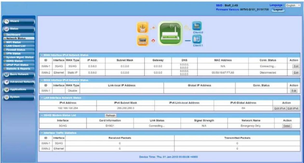
Note: You can see the first screen is located at [Status] - [Network Status] after you logged in and the screen shows the Network Connection Status below.
| WAN Interface IPv4 Network Status | ||||||||||
| ID | Interface | WAN Type | IP Addr. | Subnet Mask | Gateway | DNS | MAC Address | Conn. Status | Action | |
| WAN-1 | 3G/4G | 3G/4G | 0.0.0.0 | 0.0.0.0 | 0.0.0.0 | 0.0.0.0, 0.0.0.0 | N/A | Connecting... | Edit | |
| WAN-2 | Ethernet | Static IP | 0.0.0.0 | 0.0.0.0 | 0.0.0.0 | 0.0.0.0, 0.0.0.0 | 09:50:18:67:F7:A9 | Disconnected | Edit | |
| WAN Interface IPv6 Network Status | ||||||||||
| ID | Interface | WAN Type | Link-local IP Address | Global IP Address | Conn. Status | Action | ||||
| WAN-1 | Disable | Edit | ||||||||
| LAN Interface Network Status | ||||||||||
| IPv4 Address | IPv4 Subnet Mask | IPv6 Link-local Address | IPv6 Global Address | Action | ||||||
| 192.168.100.254 | 255.255.255.0 | /64 | Edit IPv4 Edit IPv6 | |||||||
| 3G/4G Modern Status List Refresh | ||||||||||
| Interface | Card Information | Link Status | Signal Strength | Network Name | Action | |||||
| 3G/4G | D18C1 | Connecting... | N/A | Emergency Only | Detail | |||||
| Interface Traffic Statistics | ||||||||||
| ID | Interface | Received Packets | Transmitted Packets | |||||||
| WAN-1 | 3G/4G | 0 | 0 | |||||||
| WAN-2 | Ethernet | 0 | 0 | |||||||
| WAN Interface IPv4 Network Status | |||||||||
| WAN ID | Interface | WAN Type | IP Addr. | Subnet Mask | Gateway | DNS | MAC Address | Conn. Status | Actions |
| WAN-1 | 3G/4G | 3G/4G | 0.0.0.0 | 0.0.0.0 | 0.0.0.0 | 0.0.0.0, 0.0.0.0 | N/A | Connecting... | Edit |
| WAN Interface IPv6 Network Status | |||||||||
| WAN ID | Interface | WAN Type | Link-Local IP Address | Global IP Address | Connection Status | Actions | |||
| WAN-1 | Disable | Edit | |||||||
| LAN Interface Status | |||||||||
| IPv4 Address | IPv4 Subnet Mask | IPv6 Link-Local Address | IPv6 Global Address | Actions | |||||
| 10.0.75.2 | 255.0.0.0 | /64 | Edit IPv4 Edit IPv6 | ||||||
| 3G/4G Modem Status Refresh | |||||||||
| Physical Interface | Card Information | Link Status | Signal Strength | Network Name | Actions | ||||
| 3G/4G | D16Q1 | Connecting... | N/A | Detail | |||||
| Internet Traffic Statistics | |||||||||
| WAN ID | Physical Interface | Received Packets | Transmitted Packets | ||||||
| WAN-1 | 3G/4G | 0 | 0 | ||||||
You can also check status of WiFi at WiFi Status page, connected clients at LAN Client List page, and other advanced function status at Firewall Status page, VPN Status page and System Management Status page.
4.1 Basic Network
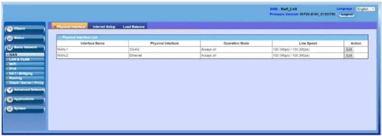
You can enter Basic Network for WAN, LAN & VLAN, WiFi, IPv6, NAT/Bridging, Routing, and Client/Server/Proxy settings as the icon shown here.
4.1.1 WAN Setup
This device is equipped with one WAN Interface to support Internet connection. You can configure it to get connection setup.
3G/4G WAN: The gateway has one 3G/4G modem built-in, please plug in SIM card and follow UI setting to setup.

Caution
☐ Please MUST POWER OFF the gateway before you Insert or remove SIM card.
☐ It will damage SIM card if you insert or remove SIM card during gateway is in operation.
- Please follow instructions at section 2.1.2.
4.1.1.1 Physical Interface
Click on the "Edit" button for the WAN interface and you can get the detail physical Interface settings and then configure the settings as well. By default, the WAN-1 interface is forced to "Always on" mode, and operates as the primary internet connection.
| Physical Interface List | ||||
| Interface Name | Physical Interface | Operation Mode | Line Speed | Action |
| WAN-1 | 3G/4G | Always on | 50 (Mbps) / 150 (Mbps) | Edit |
WAN-1: The operation mode of first interface is forced to "Always on" mode, and operates as the primary Internet connection. You can click on the respective "Edit" button and configure the rest items for this interface.
| Interface Configuration ( WAN- 1 ) | |
| Item | Setting |
| Physical Interface | 3G/4G |
| Operation Mode | Always on |
| Line Speed | 50 Mbps / 150 Mbps (Upload / Download) |
Physical Interface: Select the WAN interface from the available list. For this gateway, there is only "3G/4G" physical interface for Internet connection. To use embedded 3G/4G modem to operate as the primary Internet connection (WAN-1), please configure it with following parameters.
Operation Mode: Since there is only one physical interface as primary WAN connection for the device, its operation mode must be "Always on".
Line Speed: You can specify the upstream / downstream speed (Mbps /Kbps) for the corresponding WAN connection. Such information will be referred in QoS function to manage the traffic load for each kind of services.
VLAN Tagging: If your ISP required a VLAN tag to be inserted into the WAN packets, you can enable this setting, and enter the specified tag value.
Afterwards, click on "Save" to store your settings or click "Undo" to give up the changes.
4.1.1.2 Internet Setup
There is only 3G/4G physical WAN interface in the device that you can configure it to get proper Internet connection setup. It supports only one WAN type to connect to Internet, 3G/4G. For 3G/4G WAN type, the ISP is a mobile operator that can provide LTE, HSPA+, HSPA, WCDMA, EDGE, GPRS data services. And the device, attached with two SIM cards, can supports Dual-SIM failover mechanism for uninterrupted Internet connection.
Here after are some details of 3G/4G WAN type configuration:
3G/4G: If you have subscribed 3G/LTE data services from mobile operators. This gateway can support LTE/3G/2G depends on respective specifications. However, if your 3G data plan is not with a flat rate, it's recommended to set Connection Control mode to Connect-on-demand or Manually.
| Internet Connection List | ||||
| Interface Name | Physical Interface | Operation Mode | WAN Type | Action |
| WAN-1 | 3G/4G | Always on | 3G/4G | Edit |
4.1.1.2.1 3G/4G WAN - 3G/4G
Click on the "Edit" button for the 3G/4G WAN interface and you can get the detail WAN settings and then configure the settings as well.
| Internet Connection List | ||||
| Interface Name | Physical Interface | Operation Mode | WAN Type | Action |
| WAN-1 | 3G/4G | Always on | 3G/4G | Edit |
WAN Type : Leave it be "3G/4G".
| Internet Connection Configuration ( WAN - 1 ) | |
| Item | Setting |
| WAN Type | 3G/4G |
3G/4G WAN: The gateway has one built-in 3G/4G modems that can be configured to be WAN connection. For built-in modem, there are 1 SIM card to be inserted into the modem, please insert the SIM card and follow UI setting to setup.
| Connection with SIM-A Card | |
| Item | Setting |
| Dial-up Profile | Auto-detectionManual-configuration |
| PIN Code | (Optional) |
| ■ Connection with SIM-A Card | |
| Item | Setting |
| ► Dial-up Profile | ○ Auto-detection ● Manual-configuration |
| ► Country | Albania √ |
| ► Service Provider | Vodafone √ |
| ► APN | (Optional) |
| ► PIN Code | (Optional) |
| ► Dial Number | |
| ► Account | (Optional) |
| ► Password | (Optional) |
| ► Authentication | Auto √ |
| ► Primary DNS | (Optional) |
| ► Secondary DNS | (Optional) |
Dial-up Profile: After you subscribe 3G/4G data service, your operator will provide some information for you to setup connection, such as APN, dialed number, account or password. If you know this information exactly, you can choose
"Manual-configuration" option and type in that information by your own. Otherwise, you can select "Auto-detection" to let this gate way detect automatically. Even you choose "Manual" setting, this gateway will show responding information for your reference to setup the dial-up profile after you select country and service provide. If you choose "SIM-A First" or "SIM-A Only" for Preferred SIM Card, you need to input dial-up profile for SIM-A. Similarly, you need to input dial-up profile for SIM-B when you choose "SIM-B First" or "SIM-B Only" as your preferred done.
Country & Service Provider: When you choose "Manual-configuration" option for the Dial-up Profile, you must select the country and service provider to retrieve related parameters from system for dialing up to connect to Internet. Once system doesn't store related parameters or stores not-matched parameters, you must specify them one by one manually.
APN: When you select the target country and service provider for manual dial-up profile, system will show related APN value. Change it if it is not correct for you.
PIN Code: Enter PIN code of SIM card if your SIM card needs it to unlock.
Dial Number: Enter the dialed number that is provided by your ISP.
Account & Password: Enter Account and Password that is provided by your ISP.
Authentication: Choose "Auto", "PAP" or "CHAP" according to your ISP's authentication approach. Just keep it with "Auto" if you can't make sure.
Primary/Secondary DNS: Enter IP address of Domain Name Server. You can keep them in blank, because most ISP will assign them automatically.
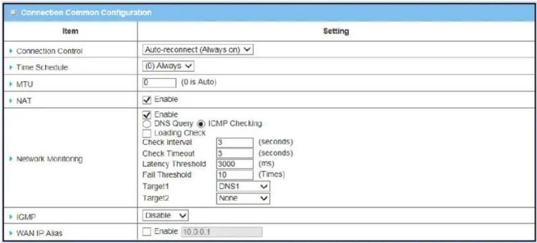
Connection Control: Select your connection control scheme from the drop list: "Auto-reconnect (Always on)", "Dial-on-demand" or "Connect Manually". If selecting "Auto-reconnect (Always son)", this gateway will start to establish Internet connection automatically since it's powered on. It's recommended to choose this scheme if for mission critical applications to ensure Internet connection is available all the time. If choosing "Dial-on-demand", this gateway won't start to establish Internet connection until local data is going to be sent to WAN side. During normal operation, this gateway will disconnect WAN connection if idle time reaches the value of "Maximum Idle Time".
If choosing "Connect Manually", this gateway won't start to establish WAN connection until you press "Connect" button on web UI. During normal operation, this gateway will disconnect WAN connection if idle time reaches the value of "Maximum Idle Time".
Time Schedule: This option allows you to limit WAN connection available in a certain time period. You can select “Always” option or a time schedule object from the schedule object list that you can find them in [System] - [Scheduling].
MTU: MTU refers to "Maximum Transmit Unit". Different WAN types of connection will have different value. You can leave it with 0 (Auto) if you are not sure about this setting.
NAT: By default, it is enabled. If you disable this option, there will be no NAT mechanism between LAN side and WAN side.
Network Monitoring: You can do preferred settings by using this feature to monitor the connection status of WAN interface. Checking mechanism depends on several parameters defined here. The network monitoring provides the WAN interface status and then system can prevent embedded 3G/LTE modem from some sort of auto-timeout and disconnects from the Internet after a period of inactivity.
Enable: Check the box to do Network Monitoring. By default, it is checked.
DNS Query/ ICMP Checking: Do the keep alive through DNS query packets or ICMP packets.
Loading Checking: The response time of replied keep-alive packets may increase when WAN bandwidth is fully occupied. To avoid keep-alive feature work abnormally, enable this option will stop sending keep-alive packets when there are continuous incoming and outgoing data packets passing through WAN connection. By default, the Loading Checking is enabled.
Check Interval: Indicate how often to send keep-alive packet.
Check Time out: Set allowance of time period to receive response of keep-alive packet. If this gateway doesn't receive response with in this time period, this gateway will record this keep alive is failed.
Latency Threshold: Set acceptance of response time. This gateway will record this keep-alive check is failed if the response time of replied packet is longer than this setting.
Fail Threshold: Times of failed checking. This WAN connection will be recognized as broken if the times of continuous failed keep-alive checking equals to this value.
Target 1/ Target 2: Set host that is used for keep alive checking. It can be DNS1, DNS2, default Gateway, or other host that you need to input IP address manually.
IGMP: Enable or disable multi cast traffics from Internet. You may enable as auto mode or select by the option list of IGMPv1, IGMPv2, IGMPv3 and Auto.
WAN IP Alias: The device supports 2 WAN IP addresses for a physical interface, one is for primary connection that provides users/devices in the LAN to access Internet; the other is a virtual connection that let remote user to manage this device.
Click on the "Edit" button for the Ethernet WAN interface and you can get the detail WAN settings and then configure the settings as well. The device provides "Static IP Address", "Dynamic IP Address", "PPP over Ethernet", "PPTP" and "L2TP" WAN types for the Ethernet WAN interface to connect to the Internet.

4.1.1.2.2.1 Dynamic IP Address
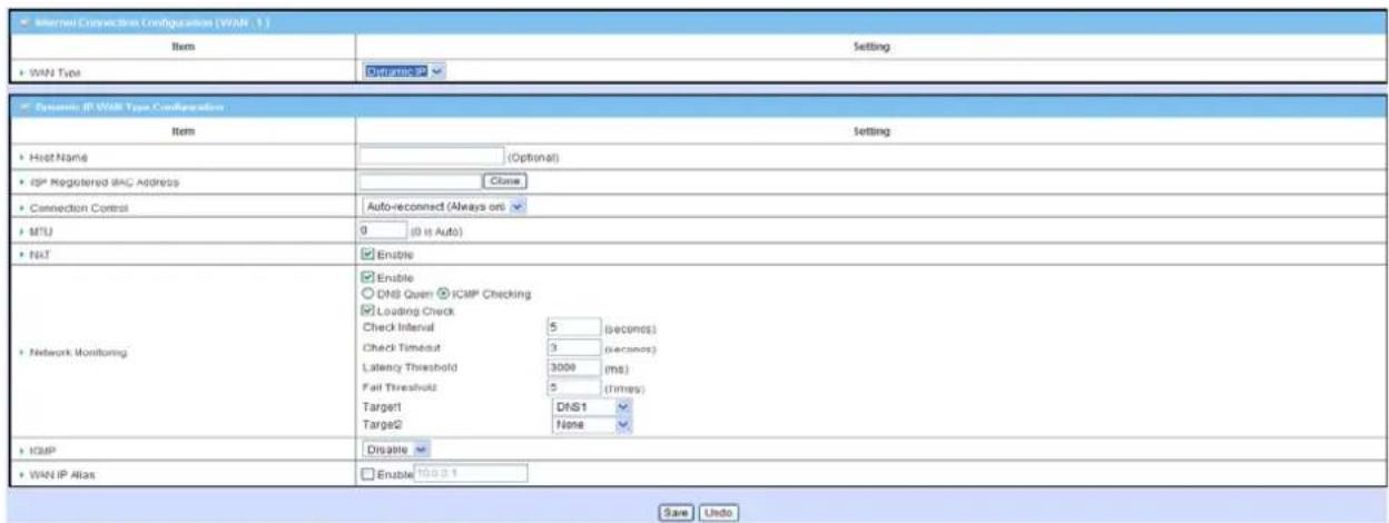
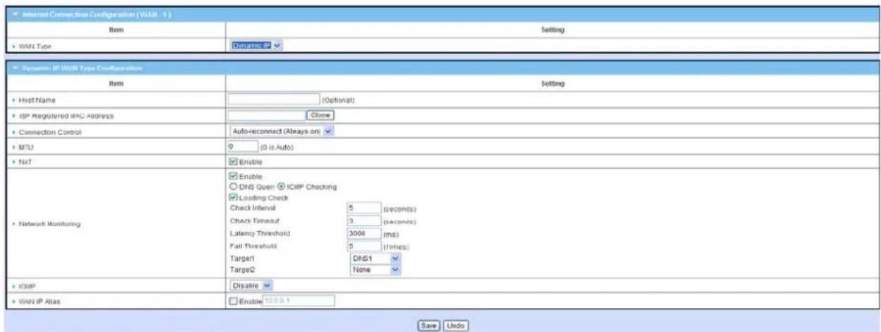
WAN Type: Choose "Dynamic IP" from the drop list.
Host Name: Optional, required by some ISPs. For example: @Home
ISP registered MAC Address: Some ISP would ask you to register a MAC address for Internet connection. In this case, you need to enter the registered MAC address here, or simply press “Clone” button to copy MAC address of your PC to this field.
Connection Control: Select your connection control scheme from the drop list: "Auto-reconnect (Always on)", "Dial-on-demand" or "Manually". If selecting "Auto-reconnect (Always on)", this gateway will start to establish Internet connection automatically since it's powered on. It's recommended to choose this scheme if for mission critical applications to ensure Internet connection is available all the time. If choosing "Dial-on-demand", this gateway won't start to establish Internet connection until local data is going to be sent to WAN side. After that, this gateway will disconnect WAN connection if idle time reaches value of Maximum Idle Time. If choosing "Manually", this gateway won't start to establish WAN connection until you press "Connect" button on web UI. After that, this gateway will disconnect WAN connection if idle time reaches value of Maximum Idle Time.
MTU: Most ISP offers MTU value to users. The default value is 0 (auto).
NAT: By default, it is enabled. If you disable this option, there will be no NAT mechanism between LAN side and WAN side.
Network Monitoring: You can do preferred settings by using this feature to monitor the connection status of WAN interface. Checking mechanism depends on several parameters defined here. The network monitoring provides the WAN interface status and then system can prevent embedded 3G/LTE modem from some sort of auto-timeout and disconnects from the Internet after a period of inactivity.
Enable: Check the box to do Network Monitoring.
DNS Query/ICMP Checking: Do the keep alive through DNS query packets or ICMP packets.
Loading Checking: The response time of replied keep-alive packets may increase when WAN bandwidth is fully occupied. To avoid keep-alive feature work abnormally, enable this option will stop sending keep-alive packets when there are continuous incoming and outgoing data packets passing through WAN connection.
Check Interval: Indicate how often to send keep-alive packet.
Check Timeout: Set allowance of time period to receive response of keep-alive packet. If this gateway doesn't receive response within this time period, this gateway will record this keep alive is failed.
Latency Threshold: Set acceptance of response time. This gateway will record this keep-alive check is failed if the response time of replied packet is longer than this setting.
Fail Threshold: Times of failed checking. This WAN connection will be recognized as broken if the times of continuous failed keep-alive checking equals to this value.
Target1/Target2: Set host that is used for keep alive checking. It can be DNS1, DNS2, default Gateway, or other host that you need to input IP address manually.
IGMP: Enable or disable multicast traffics from Internet. You may enable as auto mode or select by IGMP v1, IGMP v2, IGMP v3 or Auto.
WAN IP Alias: In some cases, ISP will provide you another fixed IP address for management purpose. You can enter that IP address in this field.
4.1.1.2.2.2 Static IP address
Select this option if ISP provides a fixed IP address to you. You will need to enter in the IP address, subnet mask, and gateway address, provided to you by your ISP. Each IP address entered in the fields must be in the appropriate IP form, which is four IP octets separated by a dot (x.x.x.x). The gateway will not accept the IP address if the format is not correct.

| Static IP WAN Type Configuration | |
| Item | Setting |
| WAN IP Address | 192.168.122.174 |
| WAN Subnet Mask | 255.255.255.0 |
| WAN Gateway | 192.168.122.230 |
| Primary DNS | 8.8.8.8 |
| Secondary DNS | 168.95.1.1 |
| MTU | 0 (0 is Auto) |
| NAT | Enable |
| Network Monitoring | Enable DNS Query ICMP Checking Loading Check Check Interval 5 (seconds) Check Timeout 3 (seconds) Latency 3000 (ms) Threshold Fail Threshold 5 (Times) Target1 DNS1 Target2 None |
| IGMP | Disable |
| WAN IP Alias | Enable 10.0.0.1 |
WAN Type: Choose "Static IP" from the drop list.
WAN IP address/Subnet Mask/ Gateway: Enter the IP address, subnet mask, and gateway address which is provided by your ISP.
Primary DNS/ Secondary DNS: Input the IP address of primary and secondary DNS server that is provided by your ISP. Secondary DNS can be ignored if only one DNS server is provided by your ISP.
MTU: Most ISP offers MTU value to users. The default value is 0 (auto).
NAT: By default, it is enabled. If you disable this option, there will be no NAT mechanism between LAN side and WAN side.
Network Monitoring: You can do preferred settings by using this feature to monitor the connection status of WAN interface. Checking mechanism depends on several parameters defined here. The network monitoring provides the WAN interface status and then system can prevent embedded 3G/LTE modem from some sort of auto-timeout and disconnects from the Internet after a period of inactivity.
Enable: Check the box to do Network Monitoring.
DNS Query/ICMP Checking: Do the keep alive through DNS query packets or ICMP packets.
Loading Checking: The response time of replied keep-alive packets may increase when WAN bandwidth is fully occupied. To avoid keep-alive feature work abnormally, enable this option will stop sending keep-alive packets when there are continuous incoming and outgoing data packets passing through WAN connection.
Check Interval: Indicate how often to send keep-alive packet.
Check Timeout: Set allowance of time period to receive response of keep-alive packet. If this gateway doesn't receive response within this time period, this gateway will record this keep alive is failed.
Latency Threshold: Set acceptance of response time. This gateway will record this keep-alive check is failed if the response time of replied packet is longer than this setting.
Fail Threshold: Times of failed checking. This WAN connection will be recognized as broken if the times of continuous failed keep-alive checking equals to this value.
Target1/Target2: Set host that is used for keep alive checking. It can be DNS1, DNS2, default Gateway, or other host that you need to input IP address manually.
IGMP: Enable or disable multicast traffics from Internet. You may enable as auto mode or select by IGMP v1, IGMP v2, IGMP v3 or Auto.
WAN IP Alias: In some cases, ISP will provide you another fixed IP address for management purpose. You can enter that IP address in this field.
4.1.1.2.2.3 PPP over Ethernet
Select this option if your ISP requires you to use a PPPoE connection. This option is typically used for ADSL services
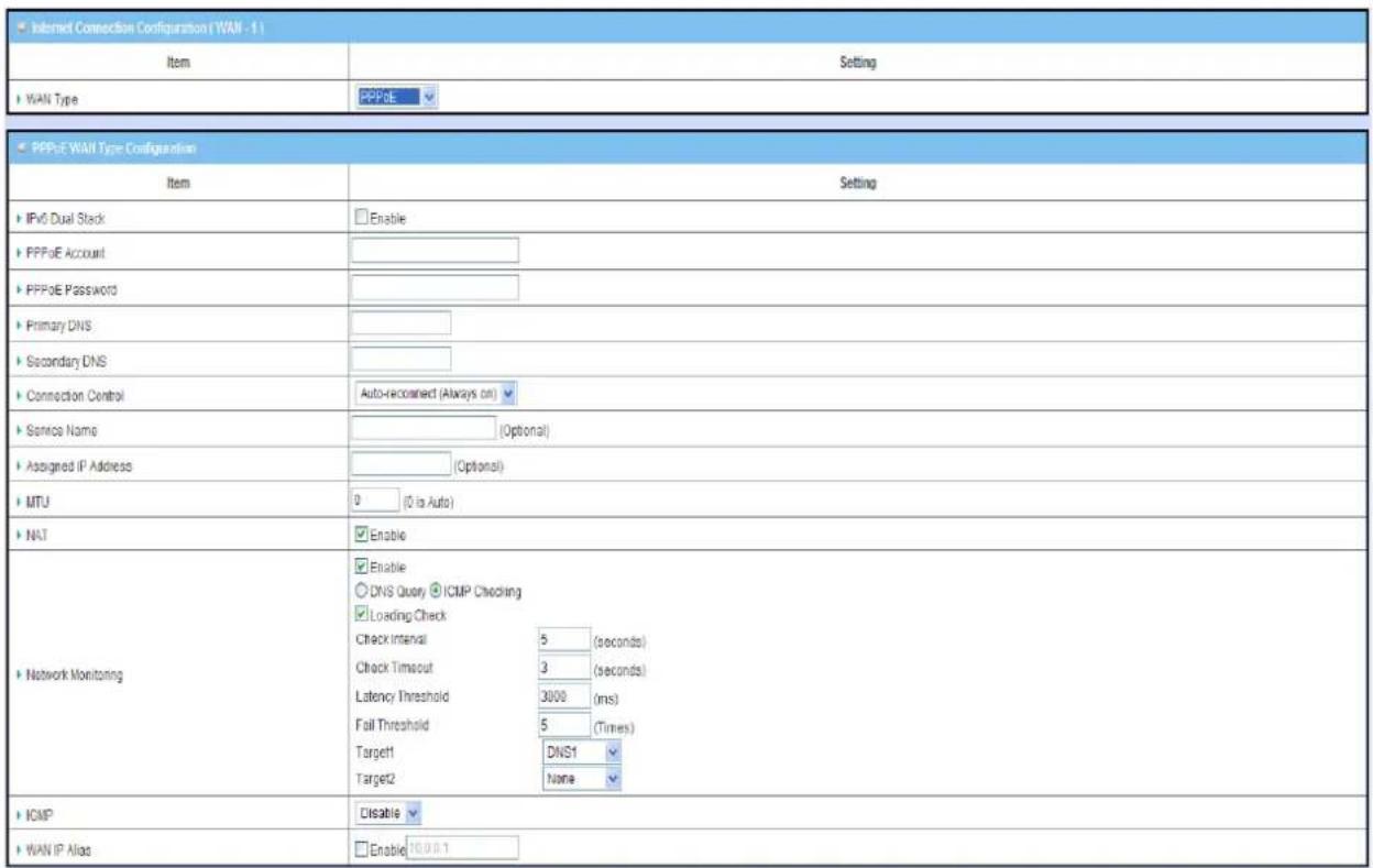

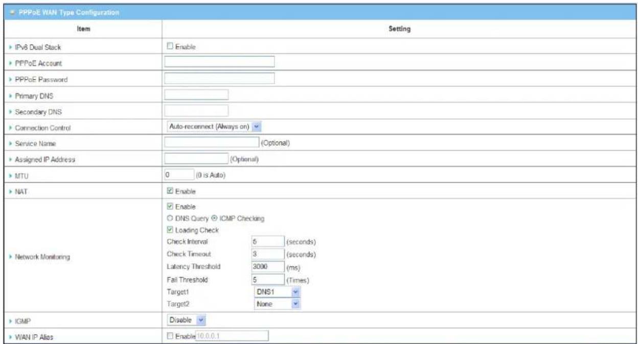

WAN Type: Choose "PPPoE" from the drop list.
IPv6 Dual Stack: You can enable this option if your ISP provides not only one IPv4 but also one IPv6 address.
PPPoE Account and Password: The account and password your ISP assigned to you. Please note the account and password is case sensitive. For security concern, the password you input won't be displayed on web UI.
Primary DNS/ Secondary DNS: In most cases, ISP will assign DNS server automatically after PPPoE connection is established. Input the IP address of primary and secondary DNS server manually if required.
Connection Control: Select your connection control scheme from the drop list: "Auto-reconnect (Always-on)", "Dial-on-demand" or "Manually". If selecting "Auto-reconnect (Always-on)", this gateway will start to establish Internet connection automatically since it's powered on. It's recommended to choose this scheme if for mission critical applications to ensure Internet connection is available all the time. If choosing "Dial-on-demand", this gateway won't start to establish Internet connection until local data is going to be sent to WAN side. After that, this gateway will disconnect WAN connection if idle time reaches value of Maximum Idle Time. If choosing "Manually", this gateway won't start to establish WAN connection until you press "Connect" button on web UI. After that, this gateway will disconnect WAN connection if idle time reaches value of Maximum Idle Time.
Service Name/ Assigned IP Address: ISP may ask you to use a specific service name when connecting PPPoE connection. In some cases, ISP can also provide you a fixed IP address with PPPoE connection. For these cases, you need to add that information in this field.
MTU: Most ISP offers MTU value to users. The default MTU value is 0 (auto).
NAT: By default, it is enabled. If you disable this option, there will be no NAT mechanism between LAN side and WAN side.
Network Monitoring: You can do preferred settings by using this feature to monitor the connection status of WAN interface. Checking mechanism depends on several parameters defined here. The network monitoring provides the WAN interface status and then system can prevent embedded 3G/LTE modem from some sort of auto-timeout and disconnects from the Internet after a period of inactivity.
Enable: Check the box to do Network Monitoring.
DNS Query/ICMP Checking: Do the keep alive through DNS query packets or ICMP packets.
Loading Checking: The response time of replied keep-alive packets may increase when WAN bandwidth is fully occupied. To avoid keep-alive feature work abnormally, enable this option will stop sending keep-alive packets when there are continuous incoming and outgoing data packets passing through WAN connection.
Check Interval: Indicate how often to send keep-alive packet.
Check Timeout: Set allowance of time period to receive response of keep-alive packet. If this gateway doesn't receive response within this time period, this gateway will record this keep alive is failed.
Latency Threshold: Set acceptance of response time. This gateway will record this keep-alive check is failed if the response time of replied packet is longer than this setting.
Fail Threshold: Times of failed checking. This WAN connection will be recognized as broken if the times of continuous failed keep-alive checking equals to this value.
Target1/Target2: Set host that is used for keep alive checking. It can be DNS1, DNS2, default Gateway, or other host that you need to input IP address manually..
IGMP: Enable or disable multicast traffics from Internet. You may enable as auto mode or select by IGMP v1, IGMP v2, IGMP v3 or Auto.
WAN IP Alias: In some cases, ISP will provide you another fixed IP address for management purpose. You can enter that IP address in this field.
4.1.1.2.2.4 PPTP
Choose PPTP (Point-to-Point Tunneling Protocol) if your ISP used a PPTP connection. Your ISP will provide you with a username and password.
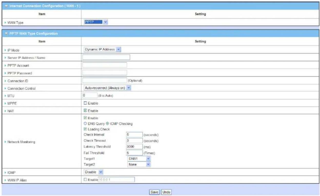

WAN Type: Choose "PPTP" from the drop list.
IP Mode: Please check the IP mode your ISP assigned, and select "Static IP Address" or "Dynamic IP Address" accordingly. If you select "Static IP Address" option, you have to specify additional "WAN IP Address", "WAN Subnet Mask", and "WAN Gateway" settings provided by your ISP.
| IP Mode | Static IP Address |
| WAN IP Address | |
| WAN Subnet Mask | |
| WAN Gateway |
Server IP Address/ Name: IP address of the PPTP server provided by ISP.
PPTP Account and Password: The account and password your ISP assigned to you. Please note the account and password is case sensitive. For security concern, the password you input won't be displayed on web UI.
Connection ID: Optional, input the connection ID if your ISP requires it.
Connection Control: Select your connection control scheme from the drop list: "Auto-reconnect (Always on)", "Dial-on-demand" or "Manually". If selecting "Auto-reconnect (Always on)", this gateway will start to establish Internet connection automatically since it's powered on. It's recommended to choose this scheme if for mission critical applications to ensure Internet connection is available all the time. If choosing "Dial-on-demand", this gateway won't start to establish Internet connection until local data is going to be sent to WAN side. After that, this gateway will disconnect WAN connection if idle time reaches value of Maximum Idle Time. If choosing "Manually", this gateway won't start to establish WAN connection until you press "Connect" button on web UI. After that, this gateway will disconnect WAN connection if idle time reaches value of Maximum Idle Time.
MTU: Most ISP offers MTU value to users. The default MTU value is 0 (auto).
MPPE (Microsoft Point-to-Point Encryption): Enable this option to add encryption on transferred and received data packets. Please check with your ISP to see if this feature is supported or not.
NAT: By default, it is enabled. If you disable this option, there will be no NAT mechanism between LAN side and WAN side.
Network Monitoring: You can do preferred settings by using this feature to monitor the connection status of WAN interface. Checking mechanism depends on several parameters defined here. The network monitoring provides the WAN interface status and then system can prevent embedded 3G/LTE modem from some sort of auto-timeout and disconnects from the Internet after a period of inactivity.
Enable: Check the box to do Network Monitoring.
DNS Query/ICMP Checking: Do the keep alive through DNS query packets or ICMP packets.
Loading Checking: The response time of replied keep-alive packets may increase when WAN bandwidth is fully occupied. To avoid keep-alive feature work abnormally, enable this option will stop sending keep-alive packets when there are continuous incoming and outgoing data packets passing through WAN connection.
Check Interval: Indicate how often to send keep-alive packet.
Check Timeout: Set allowance of time period to receive response of keep-alive packet. If this gateway doesn't receive response within this time period, this gateway will record this keep alive is failed.
Latency Threshold: Set acceptance of response time. This gateway will record this keep-alive check is failed if the response time of replied packet is longer than this setting.
Fail Threshold: Times of failed checking. This WAN connection will be recognized as broken if the times of continuous failed keep-alive checking equals to this value.
Target1/Target2: Set host that is used for keep alive checking. It can be DNS1, DNS2, default Gateway, or other host that you need to input IP address manually.
IGMP: Enable or disable multicast traffics from Internet. You may enable as auto mode or select by IGMP v1, IGMP v2, IGMP v3 or Auto.
WAN IP Alias: In some cases, ISP will provide you another fixed IP address for management purpose. You can enter that IP address in this field.
4.1.1.2.2.5 L2TP
Choose L2TP (Layer 2 Tunneling Protocol) if your ISP used a L2TP connection. Your ISP will provide you with a username and password.
![Internet Connection Configuration [WAN - 1] Item Setting WAN Type L2TP L2TP WAN Type Configuration Item Setting IP Mode Dynamic IP Address Server IP Address / Name L2TP Account L2TP Password Connection Control Auto-reconnect (Always on: MTU 0 (0 is Auto) Service Port User-defined 1702 MFPE Enable NAT Enable DNS Queen ICMP Checking Loading Check Check Interval 0 (seconds) Check Timeout 3 (seconds) Latency Threshold 3000 (ms) Fail Threshold 5 (Times) Target DNS1 Target0 None Network Monitoring IGMP Disable WAN IP Alias Enable 16.3.0.1 Save Undo](/content/2026/05/914011/images/72e1bde1ea14f482ba68cbba4203617d51f7fd499f0f36c68b433e61d85d1a7b.jpg)
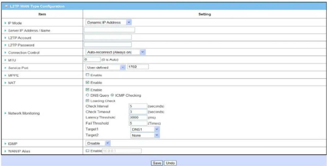
WAN Type: Choose "L2TP" from the drop list.
IP Mode: Please check the IP mode your ISP assigned, and select "Static IP Address" or "Dynamic IP Address" accordingly. If you select "Static IP Address" option, you have to specify additional "IP Address", "Subnet Mask", and "WAN Gateway IP" settings provided by your ISP.
| IP Mode | Static IP Address |
| WAN IP Address | |
| WAN Subnet Mask | |
| WAN Gateway |
Server IP Address / Name: IP address of the L2TP server provided by ISP.
L2TP Account and Password: The account and password your ISP assigned to you. Please note the account and password is case sensitive. For security concern, the password you input won't be displayed on web UI.
Connection Control: Select your connection control scheme from the drop list: "Auto-reconnect (Always on)", "Dial-on-demand" or "Manually". If selecting "Auto-reconnect (Always on)", this gateway will start to establish Internet connection automatically since it's powered on. It's recommended to choose this scheme if for mission critical applications to ensure Internet connection is available all the time. If choosing "Dial-on-demand", this gateway won't start to establish Internet connection until local data is going to be sent to WAN side. After that, this gateway will disconnect WAN connection if idle time reaches value of Maximum Idle Time. If choosing "Manually", this gateway won't start to establish WAN connection until you press "Connect" button on web UI. After that, this gateway will disconnect WAN connection if idle time reaches value of Maximum Idle Time.
MTU: Most ISP offers MTU value to users. The default MTU value is 0 (auto).
MPPE (Microsoft Point-to-Point Encryption): Enable this option to add encryption on transferred and received data packets. Please check with your ISP to see if this feature is supported or not.
NAT: By default, it is enabled. If you disable this option, there will be no NAT mechanism between LAN side and WAN side.
Network Monitoring: You can do preferred settings by using this feature to monitor the connection status of WAN interface. Checking mechanism depends on several parameters defined here. The network monitoring provides the WAN interface status and then system can prevent embedded 3G/LTE modem from some sort of auto-timeout and disconnects from the Internet after a period of inactivity.
Enable: Check the box to do Network Monitoring.
DNS Query/ICMP Checking: Do the keep alive through DNS query packets or ICMP packets.
Loading Checking: The response time of replied keep-alive packets may increase when WAN bandwidth is fully occupied. To avoid keep-alive feature work abnormally, enable this option will stop sending keep-alive packets when there are continuous incoming and outgoing data packets passing through WAN connection.
Check Interval: Indicate how often to send keep-alive packet.
Check Timeout: Set allowance of time period to receive response of keep-alive packet. If this gateway doesn't receive response within this time period, this gateway will record this keep alive is failed.
Latency Threshold: Set acceptance of response time. This gateway will record this keep-alive check is failed if the response time of replied packet is longer than this setting.
Fail Threshold: Times of failed checking. This WAN connection will be recognized as broken if the times of continuous failed keep-alive checking equals to this value.
Target1/Target2: Set host that is used for keep alive checking. It can be DNS1, DNS2, default Gateway, or other host that you need to input IP address manually.
IGMP: Enable or disable multicast traffics from Internet. You may enable as auto mode or select by IGMP v1, IGMP v2, IGMP v3 or Auto.
WAN IP Alias: In some cases, ISP will provide you another fixed IP address for management purpose. You can enter that IP address in this field.
This device supports multi-WAN load balance function and more than one WAN interface can access to Internet at a time. The load balance function can help you to manage the outbound traffics and to maximize the utilization of available bandwidth.
Load Balance: Enable or disable the load balance function.
Load Balance Strategy: Once you enabled the load balance function, you have to further configure which strategy is to be applied for load balancing the outbound traffics. There are three load balance strategy: "By Smart Weight", "By Priority", and "By User Policy".
4.1.1.3.2 By Smart Weight
| Configuration | |
| Item | Setting |
| Load Balance | Enable |
| Load Balance Strategy | By Smart Weight |
If you choose the "By Smart Weight" strategy, no any other setting is required. This device will automatically allocate the outbound traffics to each WAN interface.
4.1.1.3.3 By Priority

If you choose the "By Priority" strategy, you have to further specify the outbound traffic percentage for each WAN interface. The load balancing mechanism will follow these settings to allocate proper connection traffics for each WAN to access the internet.
4.1.1.3.4 By User Policy

If you choose the "By User Policy" strategy, you have to create the expected policies one by one. Click the "add" button to add your load balance policy.

You can manage the outbound traffic flows and force specific traffics to access Internet through designated WAN interface. For those traffics not covered in the user policy rules, the device will allocate the WAN interface by applying “Smart Weight” mechanism simultaneously.
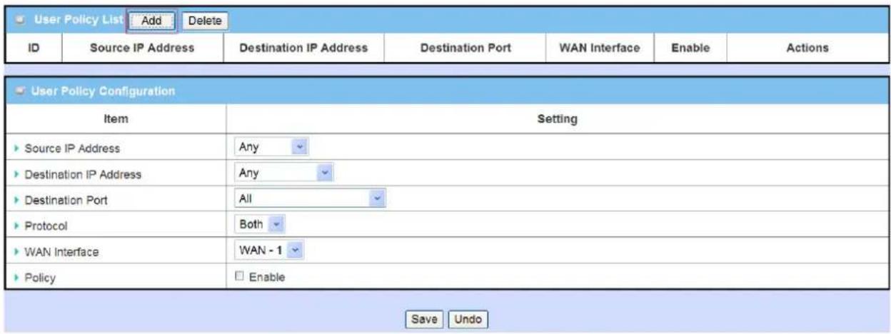
Source IP Address: Enter the expected Source IP Address for the load balance policy. It can be "Any", "Subnet", "IP Range", or "Single IP". Just choose one type of the source IP address, and specify its value as well. If you don't want to specify a certain source IP address for this policy, just leave it as "Any".
Destination IP Address: Enter the expected Destination IP Address for the load balance policy. It can be "Any", "Subnet", "IP Range", "Single IP", or "Domain Name". Just choose one type of the destination IP address, and specify its value as well. If you don't want to specify a certain destination IP address for this policy, just leave it as "Any".
Destination Port: Enter the expected Destination Port number for the load balance policy. It can be "All", "Port Range", "Single Port", or "Well-known Applications". Just choose one type of the destination port, and specify its value as well. If you don't want to specify a certain destination port for this policy, just leave it as "All".
Protocol: Enter the expected protocol type for the load balance policy. It can be "TCP", "UDP" or "Both". If you don't want to specify a certain protocol type for this policy, just leave it as "Both".
WAN Interface: Identify which WAN interface is to be selected for accessing the Internet if all of above source and destination criteria are matched for the outbound traffics.
Policy: Enable or disable this user policy.
4.1.2 LAN and VLAN Setup
This device is equipped with one Gigabit PoE Ethernet LAN port as to connect your local devices via Ethernet cables. Besides, VLAN function is provided to organize your local networks.

4.1.2.1 Ethernet LAN
Please follow the following instructions to do IPv4 Ethernet LAN Setup.
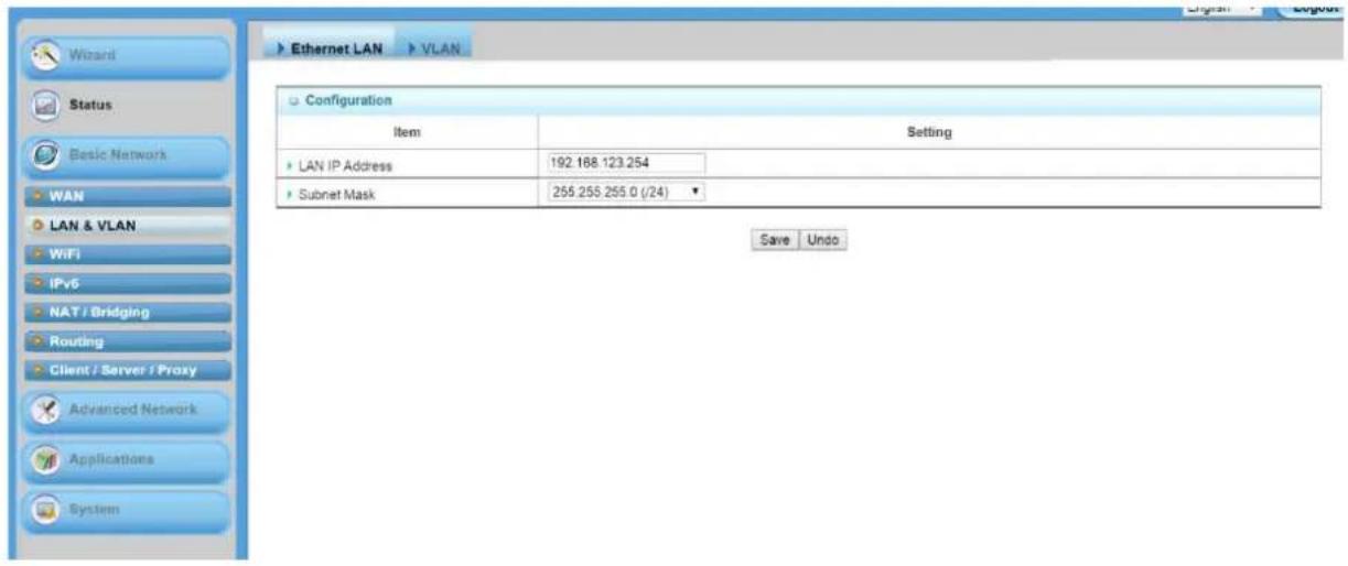
- LAN IP Address: The local IP address of this device. The computers on your network must use the LAN IP address of this device as their Default Gateway. You can change it if necessary. It's also the IP address of web UI. If you change it, you need to type new IP address in the browser to see web UI. By default, LAN IP Address is 192.168.123.254.
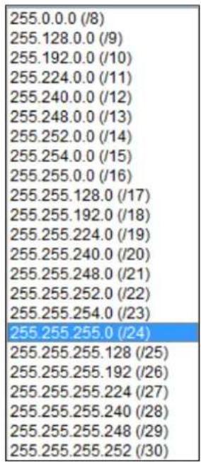
- Subnet Mask: Input your subnet mask. Subnet mask defines how many clients are allowed in one network or subnet. The default subnet mask is 255.255.255.0(/24), and it means maximum 254 IP addresses are allowed in this subnet. However, one of them is occupied by LAN IP address of this gateway, so there are maximum 253 clients allowed in LAN network. Here after are the available options for subnet mask.
4.1.2.2 VLAN
This section provides a brief description of VLANs and explains how to create and modify virtual LANs which are more commonly known as VLANs. A VLAN is a logical network under a certain switch or router device to group lots of client hosts with a specific VLAN ID. This device supports both Port-based VLAN and Tag-based VLAN. In Port-based VLAN, all client hosts belong to the same group by transferring data via some physical ports that are tagged with same VLAN ID in the device. The ports of a VLAN form an independent traffic domain in which the traffic generated by the nodes remains within the VLAN. However, in Tag-based VLAN, all packets with same VLAN ID will be treated as the same group of them and own same access property and QoS property. It is especially useful when individuals of a VLAN group are located at different floor location.
The VLAN function allows you to divide local network into different “virtual LANs”. In some cases, ISP may need router to support “VLAN tag” for certain kinds of services (e.g. IPTV) to work properly. In some cases, SMB departments are separated and located at any floor of building. All client hosts in same department should own common access property and QoS property. You can select either one operation mode, port-based VLAN or tag-based VLAN, and then configure according to your network configuration.
Please be noted, since there is only one physical Ethernet LAN port in the gateway, there is only little configuration if you choose the Port-based VLAN.
4.1.2.2.1 VLAN Scenarios
There are some common VLAN scenarios for the device as follows:
- Port-Based VLAN Tagging for DiffServ
Port-based VLAN function can group Ethernet port, Port-1, and WiFi Virtual Access Points, VAP-1\~VAP-8, together for differentiated services like Internet surfing, multimedia enjoyment, VoIP talking, and soon. Two operation modes, NAT and Bridge, can be applied to each VLAN group. One DHCP server is allocated for an NAT VLAN group to let group host member get its IP address. Thus, each host can surf Internet via the NAT mechanism of business access gateway. At bridge mode, Intranet packet flow was delivered out WAN trunk port with VLAN tag to upper link for different services.
Port-based VLAN is a group of ports on an Ethernet or Virtual Aps of Wired or Wireless Gateway that forma logical LAN segment. Following is an example. In SMB or a company, administrat or schemes out 4 segments, Lobby, Lab&Servers, Office and VoIP&IPTV. In a Wireless Gateway, administrator can configure Lobby segment with VLAN ID4. The VLAN group includes Port-4 and VAP-8(SSID: Guest) with NAT mode and DHCP-3 server equipped. He also configure Lab&Servers segment with VLAN ID3. The VLAN group includes Port-3 with NAT mode and DHCP-2 server equipped. However, he configure Office segment with VLAN ID 2. The VLAN group includes Port-2 and VAP-1 (SSID: Staff) with NAT mode and DHCP-1 server equipped. At last, administrator also configure VoIP&IPTV segment with VLAN ID11. The VLAN group includes Port-1 with bridge mode to WAN interface as shown at following diagram.
Above is the general case for 4 Ethernet LAN ports in the gateway. But the device has only one Ethernet LAN port. So, there is only one VLAN group in the device. But it also supports two different kinds of application for the Port-based VLAN tagging, NAT or Bridge.
- Tag-based VLAN Tagging for Location-free Departments
Tag-based VLAN function can group Ethernet port, Port-1, and WiFi Virtual Access Points, VAP-1 \~ VAP-8, together with different VLAN tags for deploying department subnets in Intranet. All packet flows can carry with different VLAN tags even at the same physical Ethernet port for Intranet. These flows can be directed to different destination because they have differentiated tags. The approach is very useful to group some hosts in different geographic location to be a same department.
Tag-based VLAN is also called a VLAN Trunk. The VLAN Trunk collects all packet flows with different VLAN IDs from Router device and delivers them in the Intranet. VLAN membership in a tagged VLAN is determined by VLAN ID information within the packet frames that are received on a port. Administrator can further use a VLAN switch to separate the VLAN trunk to different groups based on VLAN ID. Following is an example. In SMB or a company, administrator schemes out 3 segments, Lobby&Restaurant, Lab & Meeting Rooms and Office. In a Security VPN Gateway, administrator can configure Lobby&Restaurant segment with VLAN ID12. The VLAN group is equipped with DHCP-3 server to construct a 192.168.12.x subnet. He also configure Lab&Meeting Rooms segment with VLAN ID 11. The VLAN group is equipped with DHCP-2 server to construct a 192.168.11.x subnet for Intranet only. That is, any client host in VLAN 11 group can't access the Internet. However, he configures Office segment with VLAN ID 10. The VLAN group is equipped with DHCP-1 server to construct a 192.168.10.x subnet. In this example, VLAN 10 and 12 groups can access the Internet as following diagram.
• VLAN Group Access Control
Administrator can specify the Internet access right for all VLAN groups. He also can configure which VLAN groups can communicate each other.
VLAN Group Internet Access
Administrator can specify members of one VLAN group to be able to access Internet or not. Following is an example that VLAN groups of VID is 1 and 4 can access Internet but the one with VID is 3 can't. That is, visitors in Lobby and staffs in office can access Internet. But ones in Lab can't since security issue. Servers in Lab serve only for trusted staffs or are accessed in secure tunnels.
Inter VLAN Group Routing:
In Port-based tagging, administrator can specify member hosts of one VLAN group to be able to communicate with the ones of another VLAN group or not. This is a communication pair, and one VLAN group can join many communication pairs. But communication pair has not the transitive property. That is, A can communicate with B, and B can communicate with C, that doesn't mean A can communicate with C. An example is shown at following diagram. VLAN groups of VID is 1 and 3 can access each other but the ones between VID 3 and VID 4 and between VID 1 and VID 4 can't.
4.1.2.2.2 Port-Based VLAN
![Configuration [Help] Item Setting VLAN Type Port-based](/content/2026/05/914011/images/69cb76d6f6df821aba0fdd5006de25bf3feee175ffed21a7ecb90186ad17e5f3.jpg)
A port-based VLAN is a group of ports on an Ethernet switch or router that forma logical Ethernet segment. It also can integrate some WiFi virtual Aps into the group to own same access policies and bandwidth policies. But the device has only one Ethernet port and up to eight WiFi virtual APs. The Ethernet port can serve as NAT or Bridge type of service interface. However, WiFi VAPs can serve as NAT type only. Since only one Ethernet port, there is little configuration to be required in the device for Port-based VLAN settings.
| Port-based VLAN List | |||||||
| Port | NAT/Bridge | VLAN ID | Tx TAG | DHCP Server | Available WAN | WAN VID | Action |
| Port1 | NAT | 1 | X | DHCP 1/Enable10.0.0.0/6 | X | 0 | Edit |
| VAP1 | NAT | 1 | X | DHCP 1/Enable10.0.0.0/6 | X | 0 | Edit |
| VAP2 | NAT | 1 | X | DHCP 1/Enable10.0.0.0/6 | X | 0 | Edit |
| VAP3 | NAT | 1 | X | DHCP 1/Enable10.0.0.0/6 | X | 0 | Edit |
| VAP4 | NAT | 1 | X | DHCP 1/Enable10.0.0.0/6 | X | 0 | Edit |
| VAP5 | NAT | 1 | X | DHCP 1/Enable10.0.0.0/6 | X | 0 | Edit |
| VAP6 | NAT | 1 | X | DHCP 1/Enable10.0.0.0/6 | X | 0 | Edit |
| VAP7 | NAT | 1 | X | DHCP 1/Enable10.0.0.0/6 | X | 0 | Edit |
| VAP8 | NAT | 1 | X | DHCP 1/Enable10.0.0.0/6 | X | 0 | Edit |
| VLAN IDs | Members | NAT/Bridge | DHCP Server | Bridged WAN | Tx Tag |
| 1 | Port1, VAP-1, VAP-2, VAP-3, VAP-4, VAP-5, VAP-6, VAP-7, VAP-8 | NAT | DHCP 1 | X | No |
By default, the Ethernet LAN port (Port-1) and 8 virtual Aps belong to one VLAN, and this VLAN is a NAT type network, all the local device IP addresses are allocated by DHCP server 1. If you want to change Port-1 to be Bridge type of service interface, click on the "Edit" button.
-
Type: Select "NAT" or "Bridge" to identify if the packets are directly bridged to the WAN port or processed by NAT mechanism.
-
LANVID: Specify a VLAN identifier for this port. The ports with the same VID are in the same VLAN group.
-
TxTAG: If you want to let Intranet packets to be inserted with a "VLAN Tag" for the VLAN group, please check the "TxTAG" box.
-
DHCP Server: Specify a DHCP server for the configuring VLAN group at "NAT" type. But the device provides only one DHCP server to serve the DHCP requests from the VLAN group. Leave it be "DHCP-1".
-
WAN VID: The VLAN Tag ID that come from the ISP service. For NAT type VLAN, no WAN VLAN tag is allowed and the value is forced to "0"; For Bridge type VLAN, You have to specify the VLAN Tag value that is provided by your ISP.
-
VLAN Routing Group:
| Summary | |||
| LAN VALN Settings | |||
| Ethernet | NAT/Bridge | VLAN ID | Tx TAG |
| Port1 | NAT | 1 | |
| Wireless LAN VLAN Settings | |||
| Virtual AP | NAT/Dridge | VLAN ID | Tx TAG |
| VAP1 | NAT | 1 | |
| VAP2 | NAT | 1 | |
| VAP3 | NAT | 1 | |
| VAP4 | NAT | 1 | |
| VAP5 | NAT | 1 | |
| VAP6 | NAT | 1 | |
| VAP7 | NAT | 1 | |
| VAP8 | NAT | 1 | |
| VLAN Group Internet Access Definition | |||
| VLAN IDs | Members | Internet Access(WAN) | |
| 1 | Port1,VAP1, VAP2, VAP3, VAP4, VAPS, VAP5, VAP6, VAP7, VAP8 | Allow Edit | |
| Inter VLAN Group Routing | |||
| VLAN IDs | Members | Action | |
| Edit | |||
| Edit | |||
| Edit | |||
| Edit | |||
Above configuration example shows one VLAN group. It includes Port-1 and 8 WiFi virtual Aps, and play NAT mechanism between LAN and WAN sides. They all can access the Internet and since there is only one VLAN group, there is no other VLAN group to communicate with. About the configuration of inter-VAP routing, please refer to [Basic Network]-[WiFi] section.
Afterwards, click on "Save" to store your settings or click "Undo" to give up the changes.
4.1.2.2.3 Tag-Based VLAN
![Configuration [ Help ] Item Setting ► VLAN Type Tag-based ✓](/content/2026/05/914011/images/46cb0d629c5eec3f8a346e91f752b6cec73bf046f51b870ee66e5537e4d75c04.jpg)
The second type of VLAN is the tag-based VLAN. VLAN membership in a tagged VLAN is determined by VLAN information within the packet frames that are received on a port. This differs from a port-based VLAN, where the port VIDs assigned to the ports determine VLAN membership.
When the device receives a frame with a VLAN tag, referred to as a tagged frame, the device forwards the frame only to those ports that share the same VID.

By default, all the LAN ports and virtual Aps belong to one VLAN group, and this VLAN ID is forced to "1" but noted as "None" for avoiding misunderstanding. It is a special Tag-based VLAN group for the Intranet of device to operated, there is not a required in Intranet packets for this default VLAN group with that ID. Also be noted, there is only one Ethernet LAN port in the device.
If you want to configure your own tag-based VLANs, click on the "Edit" button on a new VLAN ID row.
| Tag-based VLAN List Add Delete | ||||
| VLAN ID | Internet | Port | VAP | DHCP Server Actions |
| None | ✓ | ✓ 1 | ✓ 1 ✓ 2 ✓ 3 ✓ 4 5 6 7 8 | DHCP 1 Edit |
| 0 | ✓ | ✓ 1 | □ 1 □ 2 □ 3 □ 4 ✓ 5 ✓ 6 ✓ 7 ✓ 8 | DHCP 1 Edit Select |
| Tag-based VLAN Summary | ||||
| Port | VLAN IDs | |||
| Port1 | 6 | |||
-
VLAN ID: Specify a VLAN tag for this VLAN group. The ports with the same VID are in the same VLAN group.
-
Internet: Specify whether this VLAN group can access Internet or not. If it is checked, all the packet will be un-tagged before it is forward to Internet, and all the packets from Internet will be tagged with the VLAN ID before it is forward to the destination belongs to this configuring VLAN group in the Intranet.
-
Port-1, VAP-1 \~ VAP-8: Specify whether they belong to the VLAN group or not. You just have to check the boxes for dedicated ports.
-
DHCP Server: Specify a DHCP server for the configuring VLAN group. This device provides only one DHCP server to serve the DHCP requests from different VLANs.
Afterwards, click on "Save" to store your settings or click "Undo" to give up the changes.
4.1.3 WiFi Setup
The gateway supports 2.4GHz 802.11n 2Tx2R MIMO WiFi, and also can be back compatible to 802.11b/g clients. WiFi settings allow you to set the wireless LAN configuration items. When the wireless configuration is done, your WiFi LAN is ready to support our local WiFi devices such as your laptop PC, smartphone, tablet, wireless printer and some portable wireless devices.
![Wizard Status Basic Network WAN LAN & VLAN WiFi IPv6 NAT / Bridging Routing Client / Server / Proxy Advanced Network Applications System Configuration > Wireless Client List > Advanced Configuration Basic Configuration [ Help ] Item Setting Operation Band 2.4G Single Band ▼ WPS 2.4G WPS Setup 2.4G WiFi Configuration Item Setting WiFi Module Enable WiFi Operation Mode AP Router Mode ▼ Green AP Enable Multiple AP Names VAP 1 Enable Max STA Enable Time Schedule (0) Always ▼ Network ID (SSID) & Broadcast Airlive Broadcast Enable WLAN Partition Enable Channel Auto ▼ WiFi System 802.11big/n Mixed ▼ Authentication WPA-PSK / WPA2-PSK ▼ Encryption Tekip / AES ▼ Preshare Key 1234567890](/content/2026/05/914011/images/28b1c83896b737deea79807c3f3ccfeee02b1ea5350c9060b4c280b52fb7a0c8.jpg)
4.1.3.1 WiFi Configuration
This device is equipped with IEEE802.11b/g/n2Tx2R wireless radio, you have to configure 2.4GHz operation band's wireless settings and then activate your WLAN.
![Basic Configuration Item Setting Operation Band 2.4G Single Band WPS 2.4G WPS Setup [ Help ]](/content/2026/05/914011/images/3017fa67ee738f17822570c8ab91fc129c6bac91717eb8ef90a893fd544a4ef8.jpg)

There are several wireless operation modes provided by this device. They are: "AP Router Mode", "WDS Hybrid Mode", and "WDS Only Mode". You can choose the expected mode from the wireless operation mode list.
4.1.3.1.1 AP Router Mode
This mode allows you to get your wired and wireless devices connected with NAT.

flowchart
graph LR
    A["Internet"] -->|3G/4G| B["VH-4GW"]
    B -->|WiFi| C["Laptop"]
    B -->|WiFi| D["Notebook"]
In this mode, this gateway is working as a WiFi AP, but also a WiFi hot spot. It means local WiFi clients can associate to it, and go to Internet. With its NAT mechanism, all of wireless clients don't need to get public IP addresses from ISP.
| Basic Configuration [ Help ] | |
| Item | Setting |
| Operation Band | 2.4G Single Band |
| WPS | 2.4G WPS Setup |
-
Operation Band: Select the WiFi operation band that you want to configure. But the device supports only 2.4G single WiFi band.
-
WPS: Click on the button to setup WPS.
| 2.4G WiFi Configuration | |
| Item | Setting |
| WiFi Module | Enable |
| WiFi Operation Mode | AP Router Mode ▼ |
| Green AP | Enable |
| Multiple AP Names | VAP 1 ▼ Enable Max.STA: □ Enable |
| Time Schedule | (0) Always ▼ |
| Network ID (SSID) & Broadcast | Airlive Broadcast ▼ Enable |
| WLAN Partition | Enable |
| Channel | Auto ▼ |
| WiFi System | 802.11b/g/n Mixed ▼ |
| Authentication | WPA-PSK / WPA2-PSK ▼ |
| Encryption | TKIP ▼ |
| Preshare Key | 1234567890 |
-
Wireless Module: Enable the wireless function.
-
Wireless Operation Mode: Choose "AP Router Mode" from the drop list.
-
Green AP: Enable the Green AP function to reduce the power consumption when there is no wireless traffic. By default, it is disabled.
-
Multiple AP Names: This device supports up to 8 SSIDs for you to manage your wireless network. You can select VAP-1 \~ VAP-8 and configure each wireless network if it is required.
-
Time Schedule: The wireless radio can be turned on according to the schedule rule you specified. By default, the wireless radio is always turned on when the wireless module is enabled. If you want to add a new schedule rule, please go to [System]-[Scheduling] menu.
-
Network ID(SSID): Network ID is used for identifying the Wireless LAN (WLAN). Client stations can roam freely over this device and other Access Points that have the same Network ID. (The factory default setting is "default")
-
SSID Broadcast: The router will broadcast beacons that have some information, including SSID so that wireless clients can know how many AP devices by scanning the network. Therefore, if this setting is configured as "Disable", the wireless clients can't find the device from beacons.
-
WLAN Partition: You can check the WLAN Partition function to separate the wireless clients. The wireless clients can't communicate each other, but they can access the internet and other Ethernet LAN devices.
-
Channel: The radio channel number. The permissible channels depend on the Regulatory Domain. The factory default setting is auto channel selection. It's recommended to choose a channel that is not used in your environment to reduce radio interference.
-
WiFi System: This gateway supports 2.4GHz 802.11b/g/n modes, so you can choose adequate WiFi system from the option list of "802.11b Only", "802.11g Only", "802.11n Only", "802.11b/g Mixed", "802.11g/n Mixed" and "802.11b/g/n Mixed" according to your requirement. The factory default setting is "802.11b/g/n Mixed".
-
Authentication & Encryption: You may select one of the following authentications to secure your wireless network: Open, Shared, Auto, WPA-PSK, WPA, WPA2-PSK, WPA2, WPA-PSK/WPA2-PSK, or WPA/WPA2.
- Open
Open system authentication simply consists of two communications. The first is an authentication request by the client that contains the station ID (typically the MAC address). This is followed by an authentication response from the AP/router (WiFi gateway) containing a success or failure message. An example of when a failure may occur is if the client's MAC address is explicitly excluded in the AP/router configuration. In this mode you can enable 802.1x feature if you have another RADIUS server for user authentication. You need to input IP address, port and shared key of RADIUS server here.
| Authentication | Open | 802.1x Enable |
| RADIUS Server | RADIUS Server IP | 0.0.0.0 |
| RADIUS Server Port | 1812 | |
| RADIUS Shared Key |
In this mode, you can only choose "None" or "WEP" in the encryption field.
- Shared
Shared key authentication relies on the fact that both stations taking part in the authentication process have the same "shared" key or pass phrase. The shared key is manually set on both the client station and the AP/router. Three types of shared key authentication are available today for home or small office WLAN environments.
- Auto
The gateway will select appropriate authentication method according to WiFi client's request automatically.
- WPA-PSK
Select Encryption mode and enter the Pre-share Key. You can fill in 64 hexadecimal (0,1,2...8,9,A,B...F)digits, or 8 to 63 ASCII characters as the pre-share key. The available encryption modes are “TKIP”, “AES”, or “TKIP/AES”. In this mode, you don't need additional RADIUS server for user authentication.
- WPA
Select Encryption mode and enter RADIUS Server related information. You have to specify the IP address and port number for the RADIUS Server, and then fill in 64 hexadecimal (0,1,2...8,9,A,B...F) digits, or 8 to 63 ASCII characters as the shared key. The key value is shared by the RADIUS server and this router. This key value must be consistent with the key value in the RADIUS server. The available encryption modes are "TKIP", "AES", or "TKIP/AES".
- WPA2-PSK
Select Encryption mode and enter the Pre-share Key. You can fill in 64 hexadecimal (0,1,2...8,9,A,B...F) digits, or 8 to 63 ASCII characters as the pre-share key. The available encryption modes are "TKIP", "AES", or "TKIP/AES". In this mode, you don't need additional RADIUS server for user authentication.
- WPA2
Select Encryption mode and enter RADIUS Server related information. You have to specify the IP address and port number for the RADIUS Server, and then fill in 64 hexadecimal (0,1,2...8,9,A,B...F) digits, or 8 to 63 ASCII characters as the shared key. The key value is shared by the RADIUS server and this router. This key value must be consistent with the key value in the RADIUS server. The available encryption modes are "TKIP", "AES", or "TKIP/AES".
- WPA-PSK/WPA2-PSK
If some of wireless clients can only support WPA-PSK, but most of them can support WPA2-PSK. You can choose this option to support both of them. Select Encryption mode and enter the Pre-share Key. You can fill in 64 hexadecimal (0,1,2...8,9,A,B...F) digits, or 8 to 63 ASCII characters as the pre-share key. In this mode, you don't need additional RADIUS server for user authentication.
- WPA/WPA2
If some of wireless clients can only support WPA, but most of them can support WPA2. You can choose this option to support both of them. Select Encryption mode and enter RADIUS Server related information. You have to specify the IP address and port number for the RADIUS Server, and then fill in 64 hexadecimal (0,1,2...8,9,A,B...F) digits, or 8 to 63 ASCII characters as the shared key. The key value is shared by the RADIUS server and this router. This key value must be consistent with the key value in the RADIUS server.
Afterwards, click on "Save" to store your settings or click "Undo" to give up the changes.
While acting as a wireless bridge, Wireless Repeater 1 and Wireless Repeater 2 can communicate with each other through wireless interface (with WDS). Thus all stations can communicate each other.
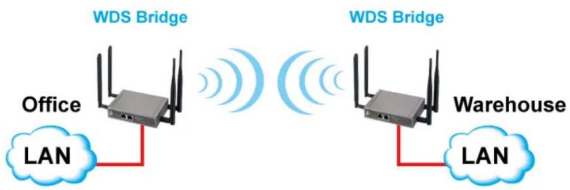
flowchart
graph LR
    A["Office LAN"] -->|Wireless Signal| B["WDS Bridge"]
    B -->|Signal| C["Office LAN"]
    D["Warehouse LAN"] -->|Signal| E["WDS Bridge"]
    E -->|Signal| F["Office LAN"]
| 2.4G WIFI Configuration | |
| Item | Setting |
| WiFi Module | Enable |
| WiFi Operation Mode | WDS Only Mode |
| Lazy Mode | Enable |
| Green AP | Enable |
| Channel | Auto |
| Authentication | Auto |
| Encryption | None |
- Wireless Module: Enable the wireless function.
-
Wireless Operation Mode: Choose "WDS Only Mode" from the drop list.
-
Lazy Mode: This device support the Lazy Mode to automatically learn the MAC address of WDS peers, you don't have to input other peer AP's MAC address. However, not all the APs can be set to enable the Lazy mode simultaneously; at least there must be one AP with all the WDS peers' MAC address filled.
-
Green AP: Enable the Green AP function to reduce the power consumption when there are no wireless traffics.
-
Channel: The radio channel number. The permissible channels depend on the Regulatory Domain. The factory default setting is auto channels election.
-
Authentication & Encryption: You may select one of the following authentications to secure your wireless network: Open, Shared, Auto, WPA-PSK and WPA2-PSK.
- Open
Open system authentication simply consists of two communications. The first is an authentication request by the client that contains the station ID (typically the MAC address). This is followed by an authentication response from the AP/router (WiFi gateway) containing a success or failure message. An example of when a failure may occur if the client's MAC address is explicitly excluded in the AP/router configuration. In this mode you can enable 802.1x feature if you have another RADIUS server for user authentication. You need to input IP address, port and shared key of RADIUS server here.
| Authentication | Open | 802.1x Enable |
| RADIUS Server | RADIUS Server IP | 0.0.0.0 |
| RADIUS Server Port | 1812 | |
| RADIUS Shared Key |
In this mode, you can only choose "None" or "WEP" in the encryption field.
- Shared
Shared key authentication relies on the fact that both stations taking part in the authentication process have the same "shared" key or pass phrase. The shared key is manually set on both the client station and the AP/router. Three types of shared key authentication are available today for home or small office WLAN environments.
- Auto
The gateway will select appropriate authentication method according to WiFi client's request automatically.
- WPA-PSK
Select Encryption mode and enter the Pre-share Key. You can fill in 64 hexadecimal (0,1,2...8,9,A,B...F) digits, or 8 to 63 ASCII characters as the pre-share key. The available encryption modes are "TKIP", "AES", or "TKIP/AES". In this mode, you don't need additional RADIUS server for user authentication.
- WPA2-PSK
Select Encryption mode and enter the Pre-share Key. You can fill in 64 hexadecimal (0,1,2...8,9,A,B...F) digits, or 8 to 63 ASCII characters as the pre-share key. The available encryption modes are "TKIP", "AES", or "TKIP/AES". In this mode, you don't need additional RADIUS server for user authentication.
- Scan Remote AP's MAC List: If you do not enable the Lazy mode, you have to enter the wireless MAC address for each WDS peer one by one. Click on the "Scan" button to get the available AP's MAC list automatically and select the expected item and copy its MAC address to the Remote APMAC1\~4 one by one.

- Remote AP MAC 1 \~ Remote AP MAC 4: If you do not enable the Lazy mode, you have to enter the wireless MAC address for each WDS peer one by one.
Afterwards, click on "Save" to store your settings or click "Undo" to give up the changes.
WDS (Wireless Distributed System) Hybrid function let this access point acts as a wireless LAN access point and a repeater at the same time. Users can use this feature to build up a large wireless network in a large space like airports, hotels and schools...etc.

| 2.4G WiFi Configuration | |
| Item | Setting |
| WiFi Module | Enable |
| WiFi Operation Mode | WDS Hybrid Mode |
| Lazy Mode | Enable |
| Green AP | Enable |
| Multiple AP Names | VAP 1 Enable Max.STA: Enable 16 (1~16) |
| Time Schedule | (0) Always |
| Network ID (SSID) & Broadcast | JP.ODG761 Broadcast Enable |
| WLAN Partition | Enable |
| Channel | Auto |
| WiFi System | 802.11b/g/n Mixed |
| Authentication | WPA2-PSK |
| Encryption | TKIP |
| Preshare Key | 1234567890 |
- Wireless Module: Enable the wireless function.
- Wireless Operation Mode: Choose "WDS Hybrid Mode" from the drop list.
- Lazy Mode: This device support the Lazy Mode to automatically learn the MAC address of WDS peers, you don't have to input other peer AP's MAC address. However, not all the APs can be set to enable the Lazy Mode simultaneously; at least there must be one AP with all the WDS peers' MAC address filled.
- Green AP: Enable the Green AP function to reduce the power consumption when there is no wireless traffic.
- Multiple AP Names: This device supports up to 8 SSIDs for you to manage your wireless network. You can select VAP-1 \~ VAP-8 and configure each wireless network if it is required.
- Time Schedule: The wireless radio can be turned on according to the schedule rule you specified. By default, the wireless radio is always turned on when the wireless module is enabled. If you want to add a new schedule rule, please go to [System]-[Scheduling] menu.
- Network ID(SSID): Network ID is used for identifying the Wireless LAN (WLAN). Client stations can roam freely over this device and other Access Points that have the same Network ID.(The factory default setting is “airlive”)
- SSID Broadcast: The router will broadcast beacons that have some information, including SSID so that wireless clients can know how many AP devices by scanning the network. Therefore, if this setting is configured as "Disable", the wireless clients can't find the device from beacons.
-
Channel: The radio channel number. The permissible channels depend on the Regulatory Domain. This channel number needs to be same as the channel number of peer AP.
-
Authentication & Encryption: You may select one of the following authentications to secure your wireless network: Open, Shared, Auto, WPA-PSK and WPA2-PSK.
- Open
Open system authentication simply consists of two communications. The first is an authentication request by the client that contains the station ID (typically the MAC address). This is followed by an authentication response from the AP/router (WiFi gateway) containing a success or failure message. An example of when a failure may occur is if the client's MAC address is explicitly excluded in the AP/router configuration. In this mode you can enable 802.1x feature if you have another RADIUS server for user authentication. You need to input IP address, port and shared key of RADIUS server here.
In this mode, you can only choose "N one" or "WEP" in the encryption field.
| Authentication | Open | 802.1x Enable |
| RADIUS Server | RADIUS Server IP | 0.0.0.0 |
| RADIUS Server Port | 1812 | |
| RADIUS Shared Key |
- Shared
Shared key authentication relies on the fact that both stations taking part in the authentication process have the same "shared" key or pass phrase. The shared key is manually set on both the client station and the AP/router. Three types of shared key authentication are available today for home or small office WLAN environments.
- Auto
The gateway will select appropriate authentication method according to WiFi client's request automatically.
- WPA-PSK
Select Encryption mode and enter the Pre-share Key. You can fill in 64 hexadecimal (0,1,2...8,9,A,B...F) digits, or 8 to 63 ASCII characters as the pre-share key. The available encryption modes are "TKIP", "AES", or "TKIP/AES". In this mode, you don't need additional RADIUS server for user authentication.
- WPA2-PSK
Select Encryption mode and enter the Pre-share Key. You can fill in 64 hexadecimal (0,1,2...8,9,A,B...F) digits, or 8 to 63 ASCII characters as the pre-share key. The available encryption modes are “TKIP”, “AES”, or “TKIP/AES”. In this mode, you don’t need additional RADIUS server for user authentication.
- Scan Remote AP's MAC List: If you do not enable the Lazy mode, you have to enter the wireless MAC address for each WDS peer one by one. Or you can press the "Scan" button to get the available AP's MAC list automatically and select the expected item and copy its MAC address to the Remote APMAC1\~4 one by one.
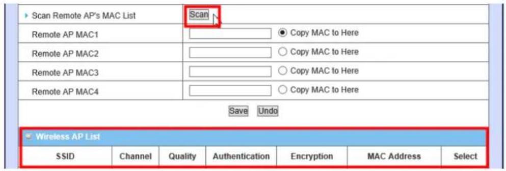
- Remote AP MAC 1 \~ Remote AP MAC 4: If you do not enable the Lazy mode, you have to enter the wireless MAC address for each WDS peer one by one.
Afterwards, click on "Save" to store your settings or click "Undo" to give up the changes.
4.1.3.1.4 WPS Setup
Once you finished the wireless settings for the following sub-sections, you can configure and enable the WPS (Wi-Fi Protection Setup) easy setup feature you're your wireless network by clinking on the "2.4G WPS Setup" button. But please be noted that if you choose "TKIP" for encryption type, WPS function is disabled.
![Basic Configuration [Help] Item Setting Operation Band 2.4G Single Band WPS 2.4G WPS Setup](/content/2026/05/914011/images/e9e052bb8afc76b5ae1e4fe4e85828e10a9abc2845ce31359b2afc454b8fa83d.jpg)
Only one wireless client is allowed to proceeding WPS connection at the same time.
![2.4G Wi-Fi Protected Setup [ Help ] Item Setting WPS Enable Configuration Status CONFIGURED Release Configuration Mode Registrar Allowed STA PIN Code WPS Trigger WPS Trigger WPS Status IDLE](/content/2026/05/914011/images/2585a86a270754e0635845b617c3d6a0b965ff13d43453aa5baf71ef69a95158.jpg)
- WPS: You can enable this function by checking "Enable" box. WPS offers a safe and easy way to allow the wireless clients connected to your wireless network.
- Configuration Status: This configuration status will be "CONFIGURED" or "UNCONFIGURED". "CONFIGURED" means WPS connection is following WiFi settings on this gateway. If it's released to "UNCONFIGURED", the WPS connection will generate a new profile.
- Configuration Mode: Select your Configuration Mode from "Registrar" or "Enrollee". In most cases, for an AP router or AP, it should be in "Registrar" mode, so that other wireless clients in "Enrollee" mode can connect to the discovered "Registrar". Briefly speaking, "Enrollee" is the initiator of WPS connection.
Registrar Mode

Enrollee Mode

- WPS Trigger [Registrar Mode]: Press this button to simulate you have push WPS button and let wireless clients to connect to this gateway in WPS PBC mode.
- Allowed STAPIN Code [Registrar Mode]: Fill the PIN code of device, so all STA clients can operate the WPS process to the device with the certificated code.
-
AP PIN Code & New Generate[Enrollee Mode]:This PIN number is required for WiFi client during WPS connection. You can press "New Generate" to get a new AP PIN.
-
WPS status: According to your setting and activity, the status will show "IDLE", "START PROCESS", or "NOT USED". The status is "IDLE" by default. If you want to start a WPS connection, you need to push "Trigger" button to change its status to "START PROCESS". Only one wireless client is allowed for each WPS connection.
If you want to start a WPS connection, you can click on the "Trigger" button of this device to change the WPS status to "STARTPROCESS" and then initiate the WPS process on other wireless client devices in two minutes to make the client device connected to the activated WLAN.
4.1.3.2 Wireless Client List
In “Wireless Client List” page, the list of connected wireless clients will be shown consequently. You can choose to see “All” of connected wireless clients, or you can
Indicate which virtual AP (SSID) you want to browse. You can check wireless clients of VAP-1\~VAP-8 individually.
![Configuration Wireless Client List Advanced Configuration Target WiFi [ Help ] Item Setting Operation Band 2.4G Multiple AP Names All Client List IP Address Host Name MAC Address Mode Rate Signal Interface Refresh](/content/2026/05/914011/images/7c99aec7ba78cf5e7c309b5ead0850ae9d18c172b705ccbe899fe8a916292801.jpg)
4.1.3.3 Advance Configuration
This device provides advanced wireless configuration for professional user to optimize the wireless performance under the specific installation environment.
| Target WiFi [Help] | |
| Item Setting | |
| Operation Band 2.4G ▼ | |
| Advanced Configuration | |
| Item Setting | |
| Regulatory Domain (1-13) | |
| Beacon Interval 100 Range: (1~1000 msec) | |
| DTIM Interval 3 Range: (1~255) | |
| RTS Threshold 2347 Range: (1~2347) | |
| Fragmentation 2346 Range: (256~2346) | |
| WMM Enable | |
| Short GI 400ns ▼ | |
| TX Rate Best ▼ | |
| RF Bandwidth Auto ▼ | |
| Transmit Power 100% ▼ |
-
Operation Band: Select the WiFi operation band that you want to configure. But the device supports only 2.4G single WiFi band.
-
Regulatory Domain: Indicate number of WiFi channel. It depends on regional government regulations.
-
Beacon interval: Beacons are broadcast packets that are sent by a wireless AP/router. The main purpose of beacon packet is let wireless clients know this AP (SSID) when doing wireless network scan.
-
DTIM interval: A DTIM is a countdown informing clients of the next window for listening to broadcast and multicast messages. When the wireless router has buffered broadcast or multicast messages for associated clients, it sends the next DTIM with a DTIM Interval value.
-
RTS Threshold: If an excessive number of wireless packet collision occurred, the wireless performance will be affected. It can be improved by adjusting the RTS/CTS (Request to Send/Clear to Send) threshold value.
-
Fragmentation: Wireless frames can be divided into smaller units(fragments) to improve performance in the presence of RF interference and at the limits of RF coverage.
-
WMM Capable: WMM can help control latency and jitter when transmitting multimedia content over a wireless connection.
-
Short GI: Time setting of Guard Interval between two Wi-Fi packets. Decrease this time interval will increase Wi-Fi data throughput. But it may cause some side-effects when the quality of Wi-Fi signal is not good. 800ns is the standard time setting of GI.
-
TX Rate: For WiFi transmit rate, you can choose "Best" for auto-adjustment according to WiFi signal quality in your environment, or you can fix it in certain TX rate. Please note the WiFi connection may be dropped if you fix at a higher date rate but in a noisy(poor RF signal quality) environment. Besides, there is only one "Best" option if following "RF Band width" parameter is set to "Auto". When RF Band width is HT40, you can set the WiFi TX Rate to be one of following option list by manual:

When RF Band width is HT20, you can set the WiFi TX Rate to be one of following option list by manual:

- RF Band width: Select Auto, HT20 or HT40 to define the RF band width for a channel. By default, it is Auto for the device.
- Transmit Power: Normally the wireless transmission power operates at 100% out power specification of this device. You can lower down the power ratio to prevent transmissions from reaching beyond your corporate/home office or designated wireless area.
4.1.4 IPv6 Setup
The growth of the Internet has created a need for more addresses than are possible with IPv4. IPv6(Internet Protocol version6) is a version of the Internet Protocol(IP) intended to succeed IPv4, which is the protocol currently used to direct almost all Internet traffic. IPv6 also implements additional features not present in IPv4. It simplifies aspects of address assignment (stateless address auto-configuration), network renumbering and router announcements when changing Internet connectivity providers. This gateway supports two types of IPv6 connection (6to4 / 6in4). Please ask your ISP of what type of IPv6 is supported before you proceed with IPv6 setup.
![Wizard Status Basic Network WAN LAN & VLAN WiFi IPv6 NAT / Bridging Routing Client / Server / Proxy Advanced Network Applications System Configuration IPv6 Configuration [ Help ] Item Setting IPv6 Enable WAN Connection Type 8to4 ▼ 6to4 WAN Type Configuration 6 to 4 Address Primary DNS Secondary DNS MLD Snooping Enable LAN Configuration Global Address 2002 0.0 —1 Link-local Address Address Auto-configuration Auto-configuration Enable Auto-configuration Type Stateless ▼ Router Advertisement Lifetime 200 (seconds) Save Undo](/content/2026/05/914011/images/41dc73500e6d1cca8b8e34ffdcd9ecb753ae96696c1a3bb28b0f12dff7eb1b67.jpg)
4.1.4.1 6 to 4
![IPv6 Configuration [ Help ] Item Setting ► IPv6 ✓ Enable ► WAN Connection Type 6 to 4 ▼](/content/2026/05/914011/images/413647433dfafb3083bc63f1300bebada4bbe258d2a9a3938eee40acbe8b7707.jpg)
When "6 to 4" is selected for the WAN Connection Type, you need to do the following settings:
6 to 4 WAN Type Configuration
| 6to4 WAN Type Configuration | |
| 6 to 4 Address | |
| Primary DNS | |
| Secondary DNS | |
| MLD Snooping | Enable |
- 6 to 4 Address: You may obtain IPv6 DNS automatically or set DNS address manually for Primary DNS address and secondary DNS address.
- Primary / Secondary DNS: Please enter IPv6 primary DNS address and secondary DNS address.
- MLD Snooping: MLD snooping, IPv6 multicast data is selectively forwarded to a list of ports that want to receive the data, instead of being flooded to all ports in a VLAN. This list is constructed by snooping IPv6 multicast control packets. If necessary in your environment, please enable this feature.
LAN Configuration
| LAN Configuration | |
| Global Address | /64 |
| Link-local Address | |
- Global Address: Please enter IPv6 global address for LAN interface.
- Link-local Address: To show the IPv6 Link-local address of LAN interface.
Address Auto-configuration
| Address Auto-configuration | |
| Auto-configuration | Enable |
| Auto-configuration Type | Stateless |
| Router Advertisement Lifetime | 200 (seconds) |
- Auto-configuration: Disable or enable this auto configuration setting.
- Auto-configuration type: You may set stateless or stateful (Dynamic IPv6).
- Router Advertisement Lifetime: You can set the time for the period that the router send (broadcast) its router advertisement. Each router periodically multicasts a Router Advertisement from each of its multicast interfaces, announcing the IP address of that interface. Hosts discover the addresses of their neighboring routers simply by listening for advertisements. When a host attached to a multicast link starts up, it may multicast a Router Solicitation to
ask for immediate advertisements, rather than waiting for the next period icons to arrive; if and only if no advertisements are forthcoming, the host may retransmit the solicitation as mall number of times, but then must desist from sending any more solicitations. Any routers that subsequently start up, or that were not discovered because of packet loss or temporary link partitioning, are eventually discovered by reception of their periodic (unsolicited) advertisements.
4.1.4.2 6 in 4
![IPv6 Configuration [ Help ] Item Setting ► IPv6 ✓ Enable ► WAN Connection Type 6 in 4 ▼](/content/2026/05/914011/images/a51e739c82afd565395df1a266a6da1974d5d0f6a472762e41270609b6db9ffb.jpg)
When "6 in 4" is selected for the WAN Connection Type, you need to do the following settings:
6 in 4 WAN Type Configuration
| 6in4 WAN Type Configuration | |
| ► Remote IPv4 Address | |
| ► Local IPv4 Address | |
| ► Local IPv6 Address | /64 |
| ► Primary DNS | |
| ► Secondary DNS | |
| ► MLD Snooping | Enable |
-
Remote / Local IPv4 and IPv6 Address: you may add remote / local Pv4 address and local IPv6 address, then set DNS address manually for Primary DNS address and secondary DNS address.
-
DNS: Please enter IPv6 primary DNS address and secondary DNS address.
-
MLD Snooping: MLD snooping, IPv6 multicast data is selectively forwarded to a list of ports that want to receive the data, instead of being flooded to all ports in a VLAN. This list is constructed by snooping IPv6 multicast control packets. If necessary in your environment, please enable this feature.
LAN Configuration
| LAN Configuration | |
| Global Address | /64 |
| Link-local Address | |
- Global Address: Please enter IPv6 global address for LAN interface.
- Link-local Address: To show the IPv6 Link-local address of LAN interface.
Address Auto-configuration
| Address Auto-configuration | |
| Auto-configuration | Enable |
| Auto-configuration Type | Stateless |
| Router Advertisement Lifetime | 200 (seconds) |
-
Auto-configuration: Disable or enable this auto configuration setting.
-
Auto-configuration Type: You may set stateless or stateful(Dynamic IPv6).
-
Router Advertisement Lifetime: You can set the time for the period that the router send (broadcast) its router advertisement. Each router periodically multicasts a Router Advertisement from each of its multicast interfaces, announcing the IP address of that interface. Hosts discover the addresses of their neighboring routers simply by listening for advertisements. When a host attached to a multicast link starts up, it may multicast a Router Solicitation to ask for immediate advertisements, rather than waiting for the next period icons to arrive; if and only if no advertisements are forthcoming, the host may retransmit the solicitation as mall number of times, but then must desist from sending any more solicitations. Any routers that subsequently start up, or that were not discovered because of packet loss or temporary link partitioning, are eventually discovered by reception of their periodic (unsolicited) advertisements.
4.1.5 NAT/Bridging
This part includes NAT related settings, such as NAT loopback, Virtual Server, Virtual Computer, Special AP, ALG, and DMZ.
![Wizard Status Basic Network WAN LAN & VLAN WiFi IPv6 NAT / Bridging Routing Client / Server / Proxy Advanced Network Applications System Configuration Virtual Server & Virtual Computer Special AP & ALG DMZ NAT Loopback [ Help ] Item Setting NAT Loopback Enable Save Undo](/content/2026/05/914011/images/adcf832d371388ef6de19c197c1a5db51ecd573f3e2da19f2ac90bb68d3c5bfd.jpg)
4.1.5.1 Configuration
| NAT Loopback | [ Help ] | |
| Item | Setting | |
| NAT Loopback | Enable | |
- NAT Loopback: Allow you to access the WAN IP address from inside your local network. This is useful when you run a server inside your network. For example, if you set a mail server at LAN side, your local devices can access this mail server through gateway's WAN IP address. You don't need to change IP address of mail server no matter you are at local side or go out. This is useful when you run a server inside your network.
4.1.5.2 Virtual Server & Virtual Computer
4.1.5.2.1 Virtual Server

This gateway's NAT firewall filters out unrecognized packets to protect your Intranet, so all hosts behind this device are invisible to the outside world. If you wish, you can make some of them accessible by enabling the Virtual Server Mapping. Press "Add" button to add new rule for Virtual Server.
A virtual server is defined as a Public Port, and all requests to this port will be redirected to the computer specified by the Server IP. Virtual Server can work with Scheduling Rules, and give user more flexibility on Access control. For the details, please refer to [System]-[Scheduling].
| Virtual Server Rule Configuration | |
| Item | Setting |
| Public Port | User-defined Service ▼ |
| Server IP | |
| Private Port | |
| Protocol | Both ▼ |
| Time Schedule | Always ▼ |
| Rule | □ Enable |
For example, if you have an FTP server (Serviceport21) at 10.0.75.1, a Web server 1(Service port 80) at 10.0.75.2, a Web server 2(Service Port 8080 and Private port 80) at 10.0.75.3, and a VPN server at 10.0.75.6, then you need to specify the following virtual server mapping table
| Public Port | Server IP | Private Port | Protocol | Rule |
| 21 | 10.0.75.1 | TCP | Enable | |
| 80 | 10.0.75.2 | TCP | Enable | |
| 8080 | 10.0.75.3 | 80 | TCP | Enable |
| 1723 | 10.0.75.6 | Both | Enable |
4.1.5.2.2 Virtual Computer
Virtual Computer enables you to use the original NAT feature, and allows you to setup the one-to-one mapping of multiple global IP address and local IP address. Press "Add" button to add new rule for Virtual Computer.

![Virtual Computer Rule Configuration [ Help ] Global IP Local IP Enable Save](/content/2026/05/914011/images/e977cb2e8c48567296b01cff2ee1e0caf6d0945ff62c4837650fcb202207c28f.jpg)
- Global IP: Enter the global IP address assigned by your ISP.
- Local IP: Enter the local IP address of your LAN PC corresponding to the global IP address.
- Enable: Check this item to enable the Virtual Computer feature.
4.1.5.3 Special AP & ALG
NAT feature can protect Intranet from outside attacks, but sometimes also blocks some applications, such as SIP VoIP. In this situation, the NAT gateway needs to do special process(ALG) for each application. This gateway can handle SIP ALG, so you need to enable this option if you want to use SIP applications at LAN side of this gateway.
| Configuration | |
| Item | Setting |
| ▶ ALG | SIP ALG ☑ Enable |
Some applications require multiple connections, like Internet games, Video conferencing, Internet telephony, etc. Because of the firewall function, these applications cannot work with a pure NAT router. The Special Applications feature allows some of these applications to work with this product. If the mechanism of Special Applications fails to make an application work, try setting your computer as the DMZ host instead.
| Special AP List Add Delete | |||||
| ID | Trigger Port | Incoming Ports | Time Schedule | Enable | Actions |
Press "Add" button to add new rule for Special AP.
| Special AP Rule Configuration [ Help ] | |
| Item | Setting |
| Trigger Port | Port: Popular Applications: -- select one -- ▼ |
| Incoming Ports | |
| Time Schedule | (0) Always ▼ |
| Rule | |
| Save | |
This device provides some predefined settings. Select your application item, and all related settings will be filled up automatically.
-
Trigger Port: The outbound port number issued by the application.
-
Incoming Ports: When the trigger packet is detected, the inbound packets sent to the specified port numbers are allowed to pass through the firewall.
-
Time Schedule: Each special AP setting can be turned off according to the schedule rule you specified. By default, it is always turned on when the rule is enabled.
-
Rule: Check this item to enable the Special AP rule.
4.1.5.4 DMZ
![Configuration [ Help ] Item Setting ► IP Address of DMZ Host Enable ► Relay DHCP Relay 192.168.123.254](/content/2026/05/914011/images/3ac04bbfcb57afe98d9ad430ae67487a48f946a60ea9935e6cb8972afd293d67.jpg)
DMZ(De Militarized Zone) Host is a host without the protection of firewall. It allows a computer to be exposed to unrestricted 2-way communication for Internet games, Video conferencing, Internet telephony and other special applications. Otherwise, if specific application is blocked by NAT mechanism, you can indicate that LAN computer as a DMZ host to solve this problem.
-
IP Address of DMZ Host: Enter IP address of Server or Host.
-
DHCP Relay: DHCP Relay Agent component relays DHCP messages between DHCP clients and DHCP servers on different IP networks. Because DHCP is a broadcast-based protocol, by default its packets do not pass through routers. If you need this feature in the environment, please enable it.
NOTE: This feature should be used only when needed.
4.1.6 Routing Setup
If you have more than one router and subnet, you will need to enable routing function to allow packets to find proper routing path and allow different subnets to communicate with each other.
![Static Routing Dynamic Routing Routing Information Configuration [ Help ] Item Setting Static Routing Enable Static Routing Rule List Add Delete ID Destination IP Subnet Mask Gateway Interface Metric Enable Actions Save Undo](/content/2026/05/914011/images/cc37f92dbfd93dfd9012d913df3a463c639db445ba7274a02e5b20e5978e8e84.jpg)
4.1.6.1 Status Routing
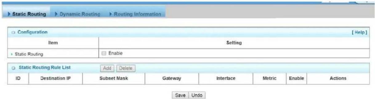
For static routing, you can specify up to 32 routing rules. The routing rules allow you to determine which physical interface addresses are utilized for outgoing IP datagrams. You can enter the destination IP address, Subnet Mask, Gateway, and Metric for each routing rule, and then enable or disable the rule by checking or un-checking the Enable checkbox.
Please click Add or Edit button to configure a static routing rule:
| Static Routing Rule Configuration | |
| Item | Setting |
| Destination IP | 140.116.82.0 |
| Subnet Mask | 255.255.255.0 |
| Gateway IP | 192.168.121.253 |
| Metric | 255 |
| Rule | Enable |
-
Destination IP: Enter the subnet network of routed destination.
-
Subnet Mask: Input your subnet mask. Subnet mask defines the range of IP address in destination network.
-
Gateway: The IP address of gateway that you want to route for this destination subnet network. The assigned gateway is required to be in the same subnet of LAN side or WAN side.
- Metric: The router uses the value to determine the best possible route. It will go in the direction of the gateway with the lowest metric.
- Rule: Check the Enable box to enable this static routing rule.
4.1.6.2 Dynamic Routing
The feature of static route is for you to maintain routing table manually. In addition, this gateway also supports dynamic routing protocol, such as RIPv1/RIPv2, OSPF, BGP for you to establish routing table automatically. The feature of dynamic routing will be very useful when there are lots of subnets in your network. Generally speaking, RIP is suitable for small network. OSPF is more suitable for medium network. BGP is more used for big network infrastructure
![Static Routing Dynamic Routing Routing Information RIP Configuration [Help] Item Setting RIP Disable ▼ OSPF Configuration Item Setting OSPF Enable Backbone Subnet OSPF Area List Add Delete ID Area Subnet Area ID Enable Actions BGP Configuration Item Setting BGP Enable Self ID BGP Neighbor List Add Delete ID Neighbor IP Neighbor ID Enable Actions Save Undo](/content/2026/05/914011/images/30b135cfce4e2e4cc74bb7bd61806327a25bb732d5238555ebaacc596905072f.jpg)
4.1.6.2.1 RIP
![RIP Configuration [ Help ] Item Setting ► RIP Disable RIPv1 RIPv2 ● OSPF Configuration](/content/2026/05/914011/images/f9a7ce472ef305a6679d503a32d9775656044bd9a4c27f37e6a34a553684888f.jpg)
RIP: Routing Information Protocol (RIP) will exchange information about destinations for computing routes throughout the network. Please select RIP v2 only if you have different subnets in your network. Otherwise, please select RIP v1 if you need this protocol
4.1.6.2.2 OSPF
OSPF is an interior gateway protocol that routes Internet Protocol(IP) packets solely within a single routing domain(autonomous system). It gathers link state information from available routers and constructs a topology map of the network. The topology determines the routing table presented to the Internet Layer which makes routing decisions based solely on the destination IP address found in IP packets.

You can enable the OSPF routing function by click on the "Enable" button for OSPF item. There are 8 area subnets can be defined in the OSPF network and enable them individually. When you finished setting, click on "Save" to store your settings. Above settings are just for examples.
4.1.6.2.3 BGP
Border Gateway Protocol(BGP) is the protocol backing the core routing decisions on the Internet. It maintains a table of IP networks or 'prefixes' which designate network reach-ability among autonomous systems(AS). It is described as a path vector protocol. BGP does not use traditional Interior Gateway Protocol (IGP) metrics, but makes routing decisions based on path, network policies and/or rule-sets. For this reason, it is more appropriately termed a reach-ability protocol rather than routing protocol.
| BGP Configuration | |
| Item | Setting |
| EGP | Enable |
| Self ID | 100 |
| ID | Neighbor IP | Neighbor ID | Enable | Actions |
| 1 | 10.101.0.1 | 101 | Edit □ Select | |
| 2 | 10.102.0.1 | 102 | Edit □ Select | |
| 3 | 10.103.0.1 | 103 | Edit □ Select | |
| 4 | 10.104.0.1 | 104 | Edit □ Select |
You can enable the BGP routing function by click on the "Setting" button and fill in the corresponding setting you're your BGP routing configuration. When you finished setting, click on "Save" to store your settings or click "Undo" to give up the changes. Above settings are just for examples.
4.1.6.3 Routing Information
| Routing Table | ||||
| Destination IP | Gateway IP | Subnet Mask | Metric | Interface |
| 111.80.62.48 | 0.0.0.0 | 255.255.255.248 | 0 | WAN-1 |
| 192.168.123.0 | 0.0.0.0 | 255.255.255.0 | 0 | tun0 |
| 127.0.0.0 | 0.0.0.0 | 255.0.0.0 | 0 | lo |
| 0.0.0.0 | 111.80.62.53 | 0.0.0.0 | 0 | WAN-1 |
A routing table, or routing information base(RIB), is a data table stored in a router or a networked computer that lists the routes to particular network destinations, and in some cases, metrics(distances) associated with those routes. The routing table contains information about the topology of the network immediately around it.
This page displays the routing table maintained by this device. It is generated according to your network configuration, above diagram is just an example.
4.1.7 Client/Server/Proxy
4.1.7.1 Dynamic DNS
How does user access your server if your WAN IP address changes all the time? One way is to register a new domain name, and maintain your own DNS server. Another simpler way is to apply a domain name to 3-party DDNS service provider. It can be free or charged.
To host your server on a changing IP address, you have to use dynamic domain name service (DDNS). Therefore, anyone wishing to reach your host only needs to know the name of it. Dynamic DNS will map the name of your host to your current IP address, which changes each time you connect your Internet service provider. This device supports most popular 3-party DDNS service provider, including TZO.com, No-IP.com, Dyn DNS.org(Dynamic), Dyn DNS.org(Custom), and DHS.org. Before you enable Dynamic DNS, you need to register an account on one of these Dynamic DNS servers that we list in Provider field.
![Dynamic DNS ▶ DHCP Server Pre-defined Domain Name List Add Delete Domain Name IP Address Definition Enable Actions Dynamic DNS [Help] Item Setting DDNS Enable Provider DynDNS.org(Dynamic) Host Name Username / E-mail Password / Key Save Undo](/content/2026/05/914011/images/2b8e5beb312ec49f4de6ea3eaf7797e2b11f400c3c72a993574813a77f557bef.jpg)
- DDNS: Check the Enable box if you would like to activate this function.
- Provider: The DDNS provider supports service for you to you're your IP (even private IP) with a certain Domain name. You could choose your favorite provider. There are following options:

- Host Name: Register a domain name to the DDNS provider. The fully domain name is concatenated with host name(you specify) and a suffix(DDNS provider specifies).
- Username/E-mail: Input user name or E-mail based on the DDNS provider you registered.
- Password/Key: Input password or key based on the DDNS provider you select.
Afterwards, click on "Save" to store your settings or click "Undo" to give up the changes.
4.1.7.2 DHCP Server
The gateway supports 1 DHCP server to serve the DHCP requests from different VLAN groups. And there is one default one whose LAN IP Address is the same one of gateway LAN interface, Subnet Mask is "255.255.255.0", and IP Pool ranges from .100 to .200 as shown at following DHCP Server List. You can add or edit one DHCP server configuration by clicking on the "Add" button behind "DHCP Server List" or the "Edit" button at the end of DHCP server information.
There are one additional button can be used to show the fixed mapping bet between
MAC address and IP address of local client hosts as following diagram.

4.1.7.2.2 DHCP Server Configuration

- DHCP Server: Choose DHCP Server to Enable. If you enable the DHCP Server function, this gateway will assign IP address to LAN computers or devices through DHCP protocol. This device provides up to 4 DHCP servers to serve the DHCP requests from different VLANs.
-
LAN IP Address: Specify the local IP address of the enabled DHCP Server. It's the LAN IP address of this gateway for DHCP-1 server. Normally, this IP address will be also the default gateway of local computers and devices.
-
Subnet Mask: Select the subnet mask for the specific DHCP-n server. Subnet Mask define show many clients are allowed in one network or subnet. The default subnet mask is 255.255.255.0/24, and it means maximum 254 IP addresses are allowed in this subnet. However, one of them is occupied by LAN IP address of this gateway, so there are maximum 253 clients allowed in LAN network. Here after are the available options for subnet mask.
| 255.0.0.0 (/8) |
| 255.128.0.0 (/9) |
| 255.192.0.0 (/10) |
| 255.224.0.0 (/11) |
| 255.240.0.0 (/12) |
| 255.248.0.0 (/13) |
| 255.252.0.0 (/14) |
| 255.254.0.0 (/15) |
| 255.255.0.0 (/16) |
| 255.255.128.0 (/17) |
| 255.255.192.0 (/18) |
| 255.255.224.0 (/19) |
| 255.255.240.0 (/20) |
| 255.255.248.0 (/21) |
| 255.255.252.0 (/22) |
| 255.255.254.0 (/23) |
| 255.255.255.0 (/24) |
| 255.255.255.128 (/25) |
| 255.255.255.192 (/26) |
| 255.255.255.224 (/27) |
| 255.255.255.240 (/28) |
| 255.255.255.248 (/29) |
| 255.255.255.252 (/30) |
-
IP Pool Starting/Ending Address: Whenever there is a request, the DHCP server will automatically allocate an unused IP address from the IP address pool to the requesting computer. You must specify the starting/ending address of the IP address pool. Please note the number of IP address in this IP pool must less than the maximum number of subnet network that according to the subnet mask you set.
-
Lease Time: DHCP lease time to the DHCP client.
-
Domain Name: Optional, this information will be passed to the clients.
-
Primary DNS/Secondary DNS: Optional. This feature allows you to assign DNS Servers.
-
Primary WINS/Secondary WINS: Optional. This feature allows you to assign WINS Servers.
-
Gateway: Optional. Gateway address would be the IP address of an alternate Gateway. This function enables you to assign another gateway to your local computer when DHCP server offers IP address. For an example, this gateway will assign IP address to local computers, but local computers will go to Internet through another gateway.
-
Server : To enable or disable the Server function
4.1.7.2.3 Fixed Mapping
Press “Fixed Mapping ...” button at the bottom of the DHCP server list page and you can specify a certain IP address for designated local device (MAC address) by manual, so that the DHCP Server will reserve the special IPs for designated devices. For internal servers, you can use this feature to ensure each of them receives same IP address all the time.
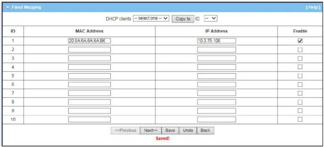
4.2 Advanced Network
This device also supports many advanced network features, such as Firewall, QoS&Bandwidth Management, VPN Security, Redundancy, System Management and Certificate. You can finish those configurations in this section.
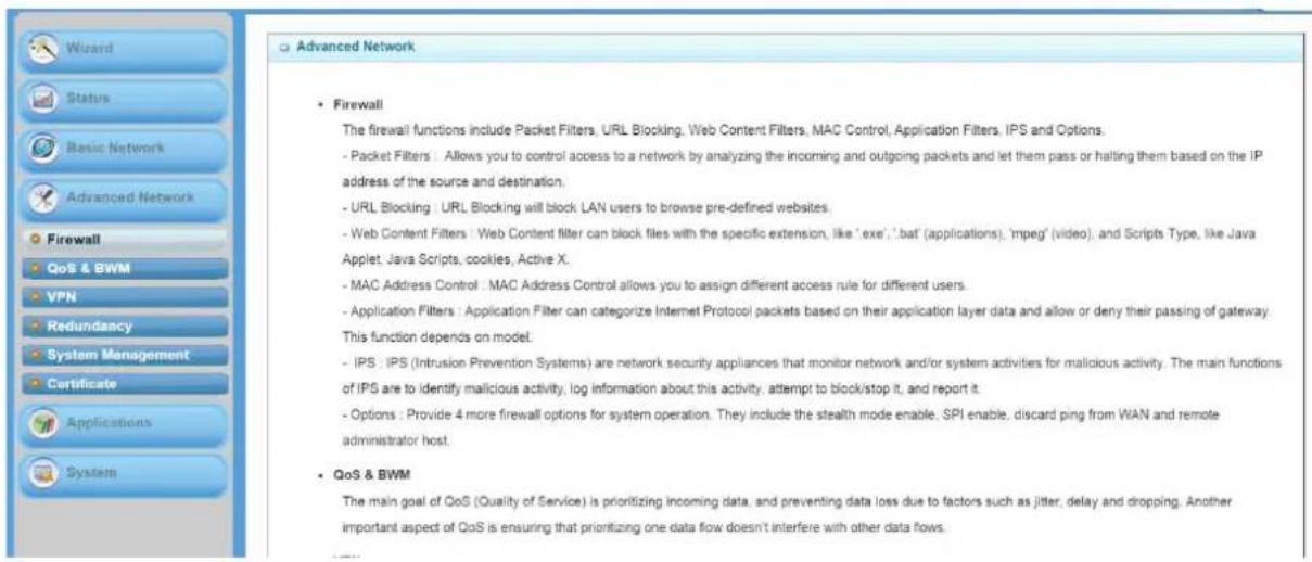
4.2.1 Firewall
The firewall functions include Packet Filters, URL Blocking, Web Content Filters, MAC Control, Application Filters, IPS and some firewall options.
4.2.1.1 Configuration
One Firewall Enable checkbox lets you activate some firewall functions that you want.

4.2.1.2 Packet Filters
Packet Filters function can let you define both outbound filter and inbound filter rules by specifying the source IP and destination IP in a rule. It enables you to control what packets are allowed or blocked to pass the router. Outbound filters are applied to all outbound packets. However, inbound filters are applied to packets that destined to virtual servers or DMZ host/port only.
![Configuration Packet Filters URL Blocking Web Content Filters MAC Control Application Filters IPS Options Configuration [ Help ] Item Setting Packet Filters Enable Black List / White List Allow all to pass except those match the following rules . Log Alert Enable Packet Filter List Add Delete ID Rule Name From Interface To Interface Source IP Destination IP Destination Port Protocol Time Schedule Enable Actions Save Undo MAC Level](/content/2026/05/914011/images/cd39b47ed096b327c10e958b54d3b73ac9f6fc313c5f152cb820c2d123d3d85a.jpg)
4.2.1.2.1 Configuration
You can enable packet filter function here. And select one of the two filtering policies as follows. The first one is to define the black list. System will block the packets that match the active filter rules. However, the second one is the white list. System will allow the packets to pass the gateway, which match the active filter rules.
- Allow all to pass except those match the specified rules.(Black List)
- Deny all to pass except those match the specified rules.(White List)
| Configuration | [ Help ] | |
| Item | Setting | |
| Packet Filters | Enable | |
| Black List / White List | Allow all to pass except those match the following rules | |
| Log Alert | Enable | |
Besides, you also can enable the log alerting so that system will record packet blocking events when filter rules are fired. At the right upper corner of screen, one “[Help]” command let you see the on-line help message about Packet Filter function.
4.2.1.2.2 Packet Filter List
It is a list of all packet filter rules. You can add one new rule by clicking on the "Add" command button. But also you can modify some existed packet filter rules by clicking corresponding "Edit" command buttons at the end of each filter rule in the Packet Filter List. Besides, unnecessary rules can be removed by checking the "Select" box for those rules and then clicking on the "Delete" command button at the Packet Filter List caption.
| ID | Rule Name | From Interface | To Interface | Source IP | Destination IP | Destination Port | Protocol | Time Schedule | Enable | Actions |
| 1 | Block 75.2 Telnet | Any | Any | 10.0.75.2 | 0.0.0.0 | 23-23 | TCP | (0) Always | Edit Select |
4.2.1.2.3 Packet Filter Rule Configuration
It supports the adding of one new rule or the editing of one existed rule. There are some parameters need to be specified in one packet filter rule. They are Rule Name, From Interface, To Interface, Source IP, Destination IP, Destination Port, Protocol, Time Schedule and finally, the rule enable.
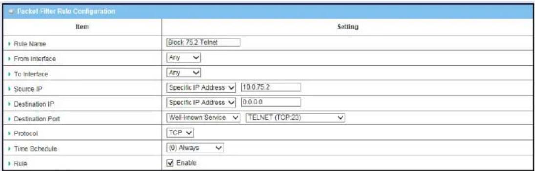
- Rule Name: The name of packet filter rule.
- From Interface: Any inter face or someone LAN interface or someone WAN interface.
- To Interface: Any interface or someone LAN interface or someone WAN interface.
- Source IP: Specify the Source IP address of packets that want to be filtered out in the packet filter rule. You can define a single IP address(4.3.2.1) or arrange of IP addresses(4.3.2.20\~30). A“0.0.0.0” implies all IP addresses.
- Destination IP: Specify the Destination IP address of packets that want to be filtered out in the packet filter rule. You can define a single IP address(4.3.2.1) or arrange of IP addresses(4.3.2.20\~30).A"0.0.0.0" implies all IP addresses.
- Destination Port: Choose "User-defined Service" to let you specify manually the destination service port of packets that want to be filtered out in the packet filter rule. You can define a single port(80) or arrange of ports(1000-1999). A "0" implies all ports are used. You also can choose one well-known service instead so that the chosen service will provide its destination port and protocol number for the rule. The supported well-known services include:
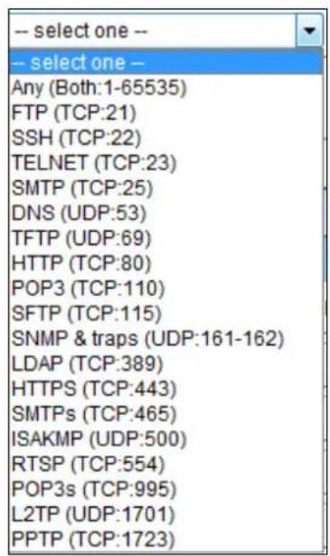
- Protocol: Specify which packet protocol is to be filtered. It can be TCP, UDP, or Both.
- Time Schedule: The rule can be turn on according to the schedule rule you specified, and give user more flexibility on access control. By default, it is always turned on when the rule is enabled. For more details, please refer to the [System] - [Scheduling] menu.
- Rule Enable: Check the enable box if you want to activate the rule. Each rule can be enabled or disabled individually.
Afterwards, click on "Save" to store your settings or click "Undo" to give up the changes.
4.2.1.3 URL Blocking
URL Blocking will block the webs containing pre-defined keywords. This feature can filter both domain input suffix(like.com or .org,etc) and a key word "bct" or "mpe".
![Configuration > Packet Filters > URL Blocking > Web Content Filters > MAC Control > Application Filters > IPS > Options Configuration [ Help ] Item Setting URL Blocking Enable Black List / White List Allow all to pass except those match the following rules. Log Alert Enable Invalid Access Web Radirection Enable URL Blocking Rule List Add Delete ID Rule Name URL / Domain Name / Keyword Destination Port Time Schedule Enable Actions Save Undo](/content/2026/05/914011/images/0c42818faea2511aef0231afdf68cd1134ee4f9789b035d6ae03b52b3f4f3131.jpg)
4.2.1.3.1 Configuration
| Configuration | [ Help ] | |
| Item | Setting | |
| URL Blocking | Enable | |
| Black List / White List | Allow all to pass except those match the following rules. | |
| Log Alert | Enable | |
| Invalid Access Web Redirection | Enable | |
- URL Blocking: Check the enable box if you want to activate URL Blocking function.
-
Black List/White List: Select one of the two filtering policies for the defined rules in URL Blocking Rule List.
-
Allow all to pass except those match the specified rules(Black List).
-
Deny all to pass except those match the specified rules(White List).
-
Log Alert: Enable the log alerting so that system will record URL blocking events when blocking rules are fired.
- Invalid Access Web Redirection: Users will see a specific web page to know their access is blocked by rules.
- [Help]: At the right upper corner of screen, one “[Help]” command let you see the on-line help message about URL Blocking function.
4.2.1.3.2 URL Blocking Rule List
It is a list of all URL Blocking rules. You can add one new rule by clicking on the "Add" command button. But also you can modify some existed URL blocking rules by clicking corresponding "Edit" command buttons at the end of each blocking rule in the URL Blocking Rule List. Besides, unnecessary rules can be removed by checking the "Select" box for those rules and then clicking on the "Delete" command button at the URL Blocking Rule List caption.
| URL Blocking Rule List Add Delete | ||||||
| ID | Rule Name | URL / Domain Name / Keyword | Destination Port | Time Schedule | Enable | Actions |
| 1 | anti-gaming | gaming | (0) Always | Edit Select | ||
4.2.1.3.3 URL Blocking Rule Configuration
It supports the adding of one new rule or the editing of one existed rule. There are some parameters need to be specified in one URL blocking rule. They are Rule Name, URL / Domain Name / Keyword, Destination Port, Time Schedule and finally, the rule enable.

- Rule Name: The name of URL blocking rule.
- URL / Domain Name / Keyword: If any part of the Website's URL matches the pre-defined words, the connection will be blocked. You can enter up to 10 pre-defined words in a rule and each URL keyword is separated by ",", e.g., "google, yahoo, org"; In addition to URL keywords, it can also block the designated domain name, like "www.xxx.com", "www.123aaa.org,mma.com".
- Destination Port: Specify the destination port in URL requests that want to be blocked in the URL blocking rule. You can define a single port (80) or a range of ports (1000-1999). An empty or "0" implies all ports are used.
- Time Schedule : The rule can be turn on according to the schedule rule you specified, and give user more flexibility on access control. By default, it is always turned on when the rule is enabled. For more details, please refer to the [System] - [Scheduling] menu.
- Rule Enable: Check the enable box if you want to activate the rule. Each rule can be enabled or disabled individually.
Afterwards, click on "Save" to store your settings or click "Undo" to give up the changes.
4.2.1.4 Web Content Filters
Web Content Filters can block HTML requests with the specific extension file name, like ".exe", ".bat" (applications), "mpeg" (video), and block HTML requests with some script types, like Java Applet, Java Scripts, cookies and Active X.
![Configuration > Packet Filters > URL Blocking > Web Content Filters > MAC Control > Application Filters > IPS > Options Configuration [ Help ] Item Setting > Web Content Filters Enable > Popular File Extension List Cookie Java ActiveX > Log Alert Enable Web Content Filter List Add Delete ID Rule Name User-defined File Extension List Time Schedule Enable Actions Save Undo](/content/2026/05/914011/images/7f75c405f3ba4b6ffac4c504c2148854f0a222589c1095473fa79fcda814544b.jpg)
4.2.1.4.1 Configuration
| Configuration | |
| Item | Setting |
| Web Content Filters | Enable |
| Popular File Extension List | Cookie Java ActiveX |
| Log Alert | Enable |
- Web Content Filters: Check the Enable box if you want to enable Web Content Filters function.
- Popular File Extension List: Check which extension types, Cookie, Java, ActiveX, are to be blocked.
- Log Alert: Enable the log alerting so that system will record Web content filtering events when filtering rules are fired.
4.2.1.4.2 Web Content Filter Rule List
It is a list of all Web Content Filter rules. You can add one new rule by clicking on the "Add" command button. But also you can modify some existed Web Content Filter rules by clicking corresponding "Edit" command buttons at the end of each filtering rule in the Web Content Filter List. Besides, unnecessary rules can be removed by checking the "Select" box for those rules and then clicking on the "Delete" command button at the Web Content Filter List caption.
| ID | Rule Name | User-defined File Extension List | Time Schedule | Enable | Actions |
| 1 | execution files | exe; com | (0) Always | Edit Select |
4.2.1.4.3 Web Content Rule Configuration
It supports the adding of one new rule or the editing of one existed rule. There are some parameters need to be specified in one Web Content Filter rule. They are Rule Name, User-defined File Extension List, Time Schedule and finally, the rule enable.

- Rule Name: The name of Web Content Filter rule.
- User-defined File Extension List: You can enter up to 10 file extensions to be blocked in a rule by using ‘;’ to concatenate these file extensions.
- Schedule: The rule can be turn on according to the schedule rule you specified, and give user more flexibility on access control. By default, it is always turned on when the rule is enabled. For more details, please refer to the [System] - [Scheduling] menu.
- Enable: Check the box if you want to enable the rule. Each rule can be enabled or disabled individually.
Afterwards, click on "Save" to store your settings or click "Undo" to give up the changes.
4.2.1.5 MAC Control
MAC Control allows you to assign different access right for different users based on device's MAC address.
![Configuration > Packet Filters > URL Blocking > Web Content Filters > MAC Control > Application Filters > IPS > Options Configuration [Help] Item Setting MAC Control Enable Black List / White List Allow all to pass except those match the following rules. Log Alert Enable Known MAC from LAN PC List -- select one -- Copy to MAC Control Rule List Add Delete ID Rule Name MAC Address Time Schedule Enable Actions Save Undo](/content/2026/05/914011/images/873af4bdf1dc46de5a910a71e231c3e587497b7f1151699ee699b11813d64a3b.jpg)
4.2.1.5.1 Configuration
![Configuration [Help] Item Setting ► MAC Control ✓ Enable ► Black List / White List Allow all to pass except those match the following rules. ► Log Alert ✓ Enable ► Known MAC from LAN PC List - select one - Copy to](/content/2026/05/914011/images/babc7a199ab90957236730473e9eb38c84a3a0d93489d408621d5dc046729623.jpg)
-
MAC Control: Check the "Enable" box to activate the MAC Control function. All of the settings in this page will take effect only when "Enable" is checked.
-
Black List / White List : Select one of the two filtering policies for the defined rules.
Black List-Allow all to pass except those match the specified rules. White List-Deny all to pass except those match the specified rules
-
Log Alert: Enable the log alerting so that system will record MAC control events when control rules are fired.
-
Known MAC from LAN PC List: You can see all of connected clients from this list, and copy their MAC address to the MAC Control Rule Configuration window below.
4.2.1.5.2 MAC Control Rule List
It is a list of all MAC Control rules. You can add one new rule by clicking on the "Add" command button. But also you can modify some existed MAC control rules by clicking corresponding "Edit" command buttons at the end of each control rule in the MAC Control Rule List. Besides, unnecessary rules can be removed by checking the "Select" box for those rules and then clicking on the "Delete" command button at the MAC Control Rule List caption.
| ID | Rule Name | MAC Address | Time Schedule | Enable | Actions |
| 1 | Block JP NB | 20:6A:6A:6A:6A:6B | (0) Always | Edit Select |
4.2.1.5.3 MAC Control Rule Configuration
It supports the adding of one new rule or the editing of one existed rule. There are some parameters need to be specified in one MAC Control rule. They are Rule Name, MAC Address, Time Schedule and finally, the rule enable.
| MAC Control Rule Configuration | |||
| Rule Name | MAC Address (Use : to Compose) | Time Schedule | Enable |
| Block JP NB | 20 6A 6A 6A 6A 6B | Always √ | √ |
-
Rule Name: The name of Web Content Filter rule.
-
MAC Address: Input the MAC address of local device. You can input manually or copy it from Known MAC from LAN PC List. Please note the format of MAC address is like "xx:xx:xx:xx:xx:xx". "x" is a hexadecimal digit.
-
Schedule: The rule can be turn on according to the schedule rule you specified, and give user more flexibility on access control. By default, it is always turned on when the rule is enabled. For more details, please refer to the [System] - [Scheduling] menu.
-
Enable: Check the box if you want to enable the rule. Each rule can be enabled or disabled individually.
Afterwards, click on "Save" to store your settings or click "Undo" to give up the changes.
4.2.1.6 Application Filters
Application Filters can categorize Internet Protocol packets based on their application layer data and allow or deny their passing of gateway.
This device supports the application filters for various Internet chat software, P2P download, Proxy, and A/V streaming. You can select the applications to be blocked after the function is enabled, and specify the schedule rule for such Application Filters function.
![Configuration Configuration Item Setting Application Filters Enable Log Alert Enable Schedule (0) Always ▼ Chat Software QQ Enable Facebook Enable Skype Enable Alww Enable P2P Software BT(BitTorrent, BtSpint, BitComet) Enable eDonkey/eMule/Shareaza Enable HTTP Multiple Thread Download Enable Thunder Enable Baofeng Enable [Help]](/content/2026/05/914011/images/1d2470f5401d77abcdfd35d93a3b21817cc21b70482871e8a65ec6fa23cd3202.jpg)
4.2.1.6.1 Configuration

-
Application Filters: Check the "Enable" box to activate the Application Filters function. All of the settings in this page will take effect only when "Enable" is checked.
-
Log Alert: Enable the log alerting so that system will record Application Filter events when filtering rules are fired.
-
Schedule: All Application Filter rules can be turn on according to the schedule rule you specified, and give user more flexibility on access control. By default, they are always turned on when Application Filters function is enabled. For more details, please refer to the [System] - [Scheduling] menu.
4.2.1.7 IPS
IPS (Intrusion Prevention Systems) are network security appliances that monitor network and/or system activities for malicious activity. The main functions of IPS are to identify malicious activity, log information about this activity, attempt to block/stop it and report it.
You can enable the IPS function and check the listed intrusion activities if necessary. There are some intrusion prevention items need a further Threshold parameter to work properly for intrusion detection. Beside, you can enable the log alerting so that system will record intrusion events when corresponding intrusions are detected.
![Configuration Packet Filters URL Blocking Web Content Filters MAC Control Application Filters IPS Options Configuration [ Help ] Item Setting IPS Enable Log Alert Enable Intrusion Prevention Item Setting SYN Flood Defense Enable 300 Packets/second (10~10000) UDP Flood Defense Enable 300 Packets/second (10~10000) ICMP Flood Defense Enable 300 Packets/second (10~10000) Port Scan Detection Enable 200 Packets/second (10~10000) Block Land Attack Enable Block Ping of Death Enable Block IP Spoof Enable Block TCP Flag Scan Enable Block Smurf Enable Block Traceroute Enable Block Fraggle Attack Enable ARP Spoofing Defence Enable 300 Packets/second (10~10000) Save Undo](/content/2026/05/914011/images/558bbb7607df9a16d1ef0c81eb1361b4c3d0f468d56e334ac556c0754d7001f5.jpg)
4.2.1.8 Options
![Configuration > Packet Filters > URL Blocking > Web Content Filters > MAC Control > Application Filters > IPS > Options Firewall Options [ Help ] Item Setting Stealth Mode Enable SPI Enable Discard Ping from WAN Enable Remote Administrator Hosts (IP / Mask : Port) 0.0.0.0 / 0 : 80 Enable Save Undo](/content/2026/05/914011/images/3c9c95cf1e9acbea1e2462abfad7ad53454e842a91ca73168a344285a1eb6c95.jpg)
- Stealth Mode: Enable this feature, this device will not respond to port scans from the WAN so that makes it less susceptible to discovery and attacks on the Internet.
- SPI: When this feature is enabled, the router will record the outgoing packet information pass through the router like IP address, port address, ACK, SEQ number and soon. And the router will check every incoming packet to detect if this packet is valid.
- Discard PING from WAN: If this feature is enabled, this gateway won't reply any ICMP request packet from WAN side. It means any remote host can't get response when "ping" to this gateway. "Ping" is a useful command that we use to detect if a certain host is alive or not. But it also let hacker know about this. Therefore, many Internet servers will be set to ignore IGMP request.
- Remote Administrator Hosts (IP / Mask : Port): In general, only local clients(LAN users) can browse the device's built-in webpages for device administration setting. This feature enables you to perform administration task from a certain remote host. If this feature is enabled, only the specified IP address can perform remote administration. If the specified IP address is 0.0.0.0, any host can connect with this product to perform administration task. You can use subnet mask bits"/nn" notation to specified a group of trusted IP addresses. For example,"10.1.2.0/24".
NOTE: When Remote Administration is enabled, the web server port will be configured to 80 as default. You also can change web server port to other port
Afterwards, click on "Save" to store your settings or click "Undo" to give up the changes.
4.2.2 QoS & BWM
The total amount of data traffic increases now a days as the higher demand of mobile devices, like Game/Chat/VoIP/P2P/Video/Web access. In order to pose new requirements for data transport, e.g. low latency, low data loss, the entire network must ensure them via a connection service guarantee.
The main goal of QoS & BWM(Quality of Service and Bandwidth Management) is prioritizing incoming data, and preventing data loss due to factors such as jitter, delay and dropping. Another important aspect of QoS is ensuring that prioritizing one data flow doesn't interfere with other data flows. So, QoS helps to prioritize data as it enters your router. By attaching special identification marks or headers to incoming packets, QoS determines which queue the packets enter, based on priority. This is useful when there are certain types of data you want to give higher priority to, such as voice packets given higher priority than Web data packets.
To utilize your network through put completely, administrator must define bandwidth control rules carefully to balance the utilization of network bandwidth for all users to access. It is indeed required that an access gateway satisfies there requirements of latency-critical applications, minimum access right guarantee, fair bandwidth usage for same subscribed condition and flexible bandwidth management. AirLive Security Gateway provides a Rule-based QoS to carry out the requirements.
![Configuration Rule-based QoS System Resource Configuration [ Help ] Item Setting Total Priority Queues of All WANs 6 WAN Interface WAN - 1 WAN Interface Resource Item Setting Bandwidth of Upstream 150 Mbps Bandwidth of Downstream 150 Mbps Total Connection Sessions 30000 Save Undo](/content/2026/05/914011/images/d10fb854369ebb91f469aeeb2b8c4abcb6a2234509c9f9640e7748a756e4cff7.jpg)
4.2.2.1 Configuration
| System Resource Configuration [ Help ] | |
| Item | Setting |
| Total Priority Queues of All WANs | 6 |
| WAN Interface | WAN-1 ▼ |
Before QoS & BWM function can work correctly, this gateway needs to define the resource for QoS & BWM function to utilize. They include the maximum number of priority queues that the device supports and some kinds of resources for each WAN interface. You can choose one WAN interface to define its resources, like available bandwidth of WAN connection and the number of total connection sessions. The application of Flexible Bandwidth Management on the interface can also be specified here.
| WAN Interface Resource | |
| Item | Setting |
| Bandwidth of Upstream | 50 Mbps √ |
| Bandwidth of Downstream | 150 Mbps √ |
| Total Connection Sessions | 10000 |
-
Bandwidth of Upstream: The maximum bandwidth of uplink in Mbps.
-
Bandwidth of Downstream: The maximum bandwidth of downlink in Mbps.
-
Total Connection Sessions: Input the maximum number of connection sessions for the WAN interface.
4.2.2.2 Rule-base QoS
This gateway provides lots of flexible rules for you to set QoS policies. Basically, you need to know three parts of information before you create your own policies. First, "who" needs to be managed? Second, "what" kind of service needs to be managed? The last part is "how" you prioritize. Once you get this information, you can continue to learn more details in this section.
Flexible QoS Rule Definition
- Multiple Group Categories
➢ Specify the group category in a QoS rule for the target objects that rule to be applied on.
➢ Group Category can bases on VLAN ID, MAC Address, IP Address, Host Name or Packet Length. Category depends on model.
- DiffServ
➢ Specify the service type in a QoS rule for the target packets that rule to be applied on.
Differentiated services can be base on 802.1p, DSCP, TOS, VLANID, User-defined Services and Well-known Services.
Well-known services include FTP(21), SSH(TCP:22), Telnet(23), SMTP(25), DNS(53), TFTP(UDP:69), HTTP(TCP:80), POP3(110), Auth(113), SFTP(TCP:115), SNMP&Traps(UDP:161-162), LDAP(TCP:389), HTTPS(TCP:443), SMTPs(TCP:465), ISAKMP(500), RTSP(TCP:554), POP3s(TCP:995), NetMeeting(1720), L2TP(UDP:1701) and PPTP(TCP:1723).
• Available Control Functions
There are 4 resources can be applied in a QoS rule: bandwidth, connection sessions, priority queues and DiffServ Code Point (DSCP). Control function that acts on target objects for specific services of packet flow is based on these resources.
For bandwidth resource, control functions include guaranteeing bandwidth and limiting bandwidth. For priority queuere source, control function is setting priority. For DSCP resource, control function is DSCP marking. The last resource is Connection Sessions; the related control function is limiting connection sessions.
• Individual / Group Control
One QoS rule can be applied to individual member or whole group in the target group. This feature depends on model.
- Outbound / Inbound Control
One QoS rule can be applied to the outbound or inbound direction of packet flow, even them both. This feature depends on model.
4.2.2.2.1 Configuration
It supports the activation of Rule-based QoS.
| Configuration | |
| Item | Setting |
| Rule-based Qos Enable | Enable |
| Flexible Bandwidth Management | Enable |
-
Rule-based QoS Enable: Check the box if you want to enable the QoS & BWM function.
-
Flexible Bandwidth Management: Apply flexible bandwidth management on the specific WAN interface by checking the Enable box.
4.2.2.2.2 QoS Rule List
It is a list of all QoS rules. You can add one new rule by clicking on the "Add" command button. But also you can modify some existed QoS rules by clicking corresponding "Edit" command buttons at the end of each rule in the QoS Rule List. Besides, unnecessary rules can be removed by checking the "Select" box for those rules and then clicking on the "Delete" command button at the QoS Rule List caption.
One “Clear” command button can let you clear all rules and “Restart” command button can let you restart the operation of all QoS rules.
| QoS Rule List Add Delete Clear Restart | |||||||||
| Interface | Group | Service | Resource | Control Function | Direction | Sharing Method | Time Schedule | Enable Actions | |
| All WANs | 10.0.75.8/29 | ALL | Bandwidth | 10-15 | Outbound | Group | (0) Always | Edit Select | |
| All WANs | 10.0.75.196/30 | DSCP:CS4 | DSCP | AF23 | Inbound | Group | (0) Always | Edit Select | |
| WAN - 1 | 10.0.75.16/28 | ALL | SESSION | 20000 | Outbound | Group | (0) Always | Edit Select | |
-
Add: After you enabled the rule-based QoS function, you can click on the "Add" button to create a new QoS rule.
-
Delete: After you selected some QoS rules by checking the "Select" box for each rule, you can click on the "Delete" button to remove those rules from the list.
-
Clear: Delete all existed QoS rules.
-
Restart: Press "Restart" button to re-initiate all QoS rules again.
-
Edit: Configure the specific QoS rule again.
4.2.2.2.3 QoS Rule Configuration
It supports the adding of one new rule or the editing of one existed rule. There are some parameters need to be specified in one QoS rule. They are Interface, Group, Service, Resource, Control Function, QoS Direction, Sharing Method, Time Schedule and finally, the rule enable.
| QoS Rule Configuration | |
| Item | Setting |
| Interface | All WANs |
| Group | IP 10.0.75.8 Subnet Mask: 255.265.265.248 (/20) |
| Service | ALL |
| Resource | Bandwidth |
| Control Function | Set MINR & MAXR 10 -- 15 (Mbps) |
| QoS Direction | Outbound |
| Sharing Method | Group Control |
| Time Schedule | (0) Always |
| Rule | Enable |
-
Interface: Select the WAN interface for the QoS rule.
-
Group: Specify the target client members for the rule by their VLAN ID, MAC Address, IP Address, Host Name or Group Object. These base categories depend on product models. Besides, "IP Address" group can be defined as an IP range with an IP address and its subnet mask. And "Group Object" is defined in the System -> Grouping menu. But what kinds of groups to use depend on product models.
-
Service: There are 5 options for service, Including All, DSCP, TOS, User-defined Services and Well-known Service as below.

By default, it is "All". It defines "what" kinds of service packets need to be managed. When "DSCP" is selected, another "DiffServ Code Point" value must be specified. DSCP means DiffServ Code Point, as known as advanced TOS. You can choose this option if your local service gateway supports DSCP tags. The DSCP categories that this gateway can detect areas below.
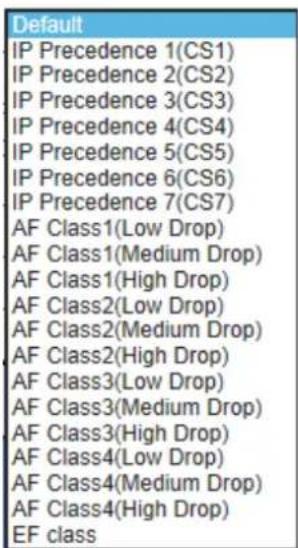
You need to choose a correct one according to your device's specification. When "TOS" is selected for Service, TOS value must be chosen from a list of 4 options. For example:

When “User-defined Services” is selected, two more parameters, Protocol Number and Service Port Range, must be defined. Protocol Number is either TCP or UDP or Both. Finally, when “Well-known Service” is selected, you can choose the well-known from a list like:
| Any(Both 1-65535) |
| FTP(21) |
| SSH(TCP:22) |
| Telnet(23) |
| SMTP(25) |
| DNS(53) |
| TFTP(UDP:69) |
| HTTP(TCP:80) |
| POP3(110) |
| Auth(113) |
| SFTP(TCP:115) |
| SNMP&Traps(UDP:161-162) |
| LDAP(TCP:389) |
| HTTPS(TCP:443) |
| SMTPs(TCP:465) |
| ISAKMP(500) |
| RTSP(TCP:554) |
| POP3s(TCP:995) |
| NetMeeting(1720) |
| L2TP(UDP:1701) |
| PPTP(TCP:1723) |
- Resource: There are 4 resources can be chosen to control in the QoS rule. They are "Bandwidth", "Connection Sessions", "Priority Queues" and "Diff fServ Code Points".
- Control Function: It depends on the chosen resource. For "Bandwidth" resource, the control function is "Set MINR & MAXR". For "Connection Sessions", the control function is "Set Session Limitation". For "Priority Queues", it is "Set Priority". However, for "DiffServ Code Points", it is "DSCP Marking" and you need specify the DSCP value additionally.
- QoS Direction: Select the traffic direction to be applied for this rule.
| Direction | |
| IN | For Inbound data |
| OUT | For Outbound data |
| BOTH | Inbound and Outbound |
-
Sharing Method: If you want to apply the value of control setting on each selected host in the "Group", you need to select "Individual Control" for Sharing Method. On the other hand, if the value of control setting wants to be applied on all selected hosts in the "Group", you need to select "Group Control". For example, you define Control Function as "Set Session Limitation" and the limited sessions are 2000 sessions. You also define Sharing Method as "Individual Control". Then, that means the maximum connection sessions of each selected host can't exceed 2000 sessions. On the contrary, changing to "Group Control", it means that group of client hosts totally can't use over 2000 connection sessions.
-
Schedule: The rule can be turn on according to the schedule rule you specified, and give user more flexibility on access control. By default, it is always turned on when the rule is enabled. For more details, please refer to the [System] - [Scheduling] menu.
- Enable: Check the box if you want to enable the rule. Each rule can be enabled or disabled individually.
Afterwards, click on "Save" to store your settings or click "Undo" to give up the changes.
Example#1 for adding a "DSCP" type QoS rule

Interface: Select "All WANs".
Group: Select "IP" and enter IP range:10.0.75.196/30.
Service: Select "DSCP" with DiffServ Code Points isCS4.
Resource: Select "DiffServ Code Points".
Control Function: Select "DSCP Marking" with "AF Class2 (High Drop)".
QoS Direction: Select "Inbound" for inbound traffic only.
☐ Sharing Method: Select "Group Control".
Schedule: Leave the default value of “(0) Always” as it is.
This rule means IP packets from all WAN interfaces to LAN IP address 10.0.75.196\~10.0.75.199 which have DiffServ code points with "IP Precedence4(CS4)" value will be modified by "DSCP Marking" control function with "AF Class2(High Drop)" value at anytime.
Example#2 for adding a "Connection Sessions" type QoS rule
| QoS Rule Configuration | |
| Item | Setting |
| Interface | WAN - 1 |
| Group | IP 10.0.75.16 Subnet Mask 255.255.255.240 (/28) |
| Service | ALL |
| Resource | Connection Sessions |
| Control Function | Set Session Limitation 20000 |
| QoS Direction | Outbound |
| Sharing Method | Group Control |
| Time Schedule | (0) Always |
| Rule | Enable |
Interface: Select "WAN-1".
Group: Select "IP" and enter IP range:10.0.75.16/28.
Service: Select "ALL".
Resource: Select "Connection Sessions".
Control Function: Select "Set Session Limitation", and set session number to 20000.
QoS Direction: Select "Outbound" for outbound traffic only. It is for the client devices under the gateway to establish multiple sessions with servers in the Internet.
☐ Sharing Method: Select "Group Control".
Schedule: Leave the default value of “(0) Always” as it is.
This rule defines that all client hosts, whose IP address is in the range of 10.0.75.16\~31, can access to the Internet and keep a maximum 20000 connection sessions totally at anytime.
4.2.3 VPN Setup
A virtual private network (VPN) extends a private network across a public network, such as the Internet. It enables a computer to send and receive data across shared or public networks as if it were directly connected to the private network, while benefitting from the functionality, security and management policies of the private network. This is done by establishing a virtual point-to-point connection through the use of dedicated connections, encryption, or a combination of the two. The tunnel technology supports data confidentiality, data origin authentication and data integrity of network information by utilizing encapsulation protocols, encryption algorithms, and hashing algorithms.
The product series supports following tunneling technologies to establish secure tunnels between multiple sites for data transferring, including IPSec, PPTP, L2TP (over IPSec) and GRE. Advanced functions include Full Tunnel, Tunnel Failover, Tunnel Load Balance, Net BIOS over IPSec, NAT Traversal and Dynamic VPN.
4.2.3.1 Configuration

To enable the VPN function, you should go to Configuration before any setting.
4.2.3.2 IPSec
Internet Protocol Security (IPSec) is a protocol suite for securing Internet Protocol(IP) communications by authenticating and encrypting each IP packet of a communication session. IPSec includes protocols for establishing mutual authentication between agents at the beginning of the session and negotiation of cryptographic keys to be used during the session.
An IPSec VPN tunnel is established between IPSec client and server. Sometimes, we call the IPSec VPN client as the initiator and the IPSec VPN server as the responder. There are two phases to negotiate between the initiator and responder during tunnel establishment, IKE phase and IPSec phase. At IKE phase, IKE authenticates IPSec peers and negotiates IKESAs(Security Association) during this phase, setting up a secure channel for negotiating IPSec SAs in phase 2. At IPSec phase, IKE negotiates IPSec SA parameters and setsup matching IPSec SAs in the peers. After these both phases, data is transferred between IPSec peers based on the IPSec parameters and keys stored in the SA database.
4.2.3.2.1 IPSec VPN Tunnel Scenarios
There are some common IPSec VPN connection scenarios as follows:
- Site to Site
The device establishes IPSec VPN tunnels with security gateway in head quarters or branch offices. Either local or remote peer gateway which can be recognized by astatic IP address or a FQDN can initiate the establishing of an IPSec VPN tunnel. Two peers of the tunnel have their own Intranets and these cure tunnel serves for data communication between these two subnets of hosts.
- Dynamic VPN
Business Security Gateway can ignore IP information of clients when using Dynamic VPN, so it is suitable for users to build VPN tunnels with Business Security Gateway from a remote mobile host or mobile site. Remote peer is a host or a site will be indicated in the negotiation packets, including what remote subnets. It must be noted that the remote peer has to initiate the tunnel establishing process first in this application scenario.
There is one more advanced IPSec VPN application:
- Site to Site – Support Full Tunnel Application
When Full Tunnel function of remote Business Security Gateway is enabled, all data traffic from remote clients behind remote Business Security Gateway will goes over the VPN tunnel. That is, if a user is operating at a PC that is in the Intranet of remote Business Security Gateway, all application packets and private at a packets from the PC will be transmitted securely in the VPN tunnel to access the resources behind local Business Security Gateway, including surfing the Internet. As a result, every time the user surfs the web for shopping or searching data on Internet, checking personal emails, or accessing company servers, all are done in a secure way through local Business Security Gateway.
4.2.3.2.2 IPSes Configuration
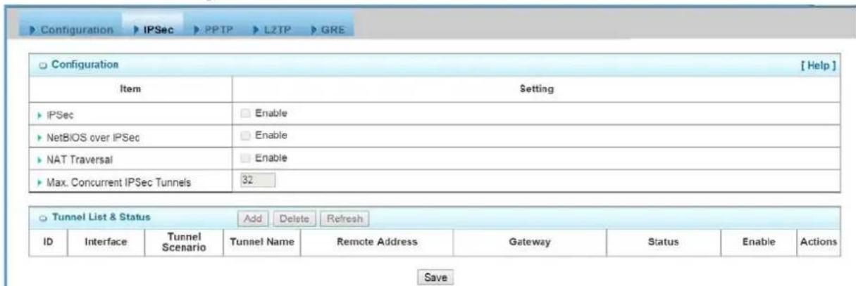
-
IPSec: You could trigger the function of IPSec VPN if you check "Enable" box.
-
Net BIOS over IPSec: If you would like two Intranets behind two Business Security Gateways to receive the Net BIOS packets from Network Neighborhood, you have to check "Enable" box.
-
NAT Traversal: Some NAT routers will block IPSec packets if they don't support
IPSec pass through you're your Business Security Gateway connects to this kind of NAT router which doesn't support IPSec pass through, you need to activate this option in your Business Security Gateway.
-
Max.Tunnels: The device supports up to 32 IPSec tunnels, but you can specify it with the number of maximum current activated IPSec tunnels that is smaller or equal to 32.
-
You can add new, edit or delete some IPSec tunnels in Tunnel List & Status as follows.
4.2.3.2.3 Tunnel List and Status
| ID | Interface | Tunnel Name | Remote Address | Gateway | Status | Enable | Actions |
| 1 | WAN 1 | IPSec-Site2Site | 10.0.76.0/255.255.255.0 | www.ipsec.com.tw | Connecting... | ☑ | Edit ☐ Select |
| 2 | WAN 1 | My Dynamic VPN | Any | Any | On | ☑ | Edit ☐ Select |
-
Add: You can add one new IPSec tunnel with Site to Site scenario by clicking the "Add" button.
-
Delete: Delete selected tunnels by checking the "Select" box at the end of each tunnel list and then clicking the "Delete" button.
-
Refresh: To refresh the Tunnel List & Status each 2 seconds by clicking on the "Refresh" button.
-
Tunnel: Check the "Enable" box to activate the IPSec tunnel.
-
Edit: You can edit one tunnel configuration by clicking the "Edit" button at the end of each tunnel list.
4.2.3.2.4 Tunnel Configuration

-
Tunnel Name: Enter the name of tunnel.
-
Interface: Decide the WAN Interface to establish the tunnel.
-
Tunnel Scenario: Support "Site to Site", "Site to Host", "Host to Site", "Host to Host" and "Dynamic VPN". Select one from them.
-
Operation Mode: Default is "Always on" and other options depend on product models.
-
Encapsulation Protocol: Default is ESP and other options depend on product models.
-
Keep-alive: Check "Enable" box to keep alive the tunnel. By default, keep-alive
method is "Ping IP" and other options depend on product models. Input the IP address of remote host that exists in the opposite side of the VPN tunnel (Ex. You can input the LAN IP address of remote Business Security Gateway). The Interval is specified with the time interval between two ping requests, and by default, it is 30 seconds. Now, the device will start to ping remote host when there is no traffic within the VPN tunnel. If the device can't get ICMP response from remote host anymore, it will terminate the VPN tunnel automatically.
4.2.3.2.5 Local & Remote Configuration
| Item | Setting |
| Local Subnet | 10.0.75.0 |
| Local Netmask | 255 255 255.0 -- select one -- ✓ -- select one -- ✓ -- select one -- ✓ -- select one -- ✓ |
| Full Tunnel | Enable |
| Remote Subnet | 10.0.76.0 |
| Remote Netmask | 255 255 255.0 -- select one -- ✓ -- select one -- ✓ -- select one -- ✓ |
| Remote Gateway | www.jpsec.com.tw (IP Address/FQDN) |
-
Local Subnet: The subnet of LAN site of local Business Security Gateway. It can be a host, a partial subnet, or the whole subnet of LAN site of local gateway. There are 5 entries for Local Subnet.
-
Local Netmask: The local netmask and associated local subnet can define a subnet domain for the local devices connected via the VPN tunnel. There are 5 entries for Local Netmask.
-
Full Tunnel: All traffic from Intranet of Business Security Gateway goes over the IPSec VPN tunnel if these packets don't match the Remote Subnet of other IPSec tunnels. That is, both application data and Internet access packets land up at the VPN concentrator.
-
Remote subnet: The subnet of LAN site of remote Business Security Gateway. It can be a host, a partial subnet, or the whole subnet of LAN site of remote gateway. There are 5 entries for Remote Subnet.
-
Remote Netmask: The remote netmask and associated remote subnet can define a subnet domain for the remote devices connected via the VPN tunnel. There are 5 entries for Remote Netmask.
-
Remote Gateway: Enter the IP address or FQDN of remote Business Security Gateway.
4.2.3.2.6 Authentication

-
Key Management: Select "IKE+Pre-shared Key" or "Manually". Other options depend on product models. By default, "IKE+Pre-shared Key" method is adopted for key management. It is the first key used in IKE phase for both VPN tunnel initiator and responder to negotiate further security keys to be used in IPSec phase. The pre-shared key must be the same for both VPN tunnel initiator and responder. When "Manually" key management is adopted, the Pre-shared is not necessary.
-
Local ID: The Type and the Value of the local Business Security Gateway must be the same as that of the Remote ID of the remote VPN peer. There are 4 types for Local ID: UserName, FQDN, User@FQDN and Key ID.
-
Remote ID: The Type and the Value of the local Business Security Gateway must be the same as that of the local ID of the remote VPN peer. There are also 4 types for Remote ID: UserName, FQDN, User@FQDN and Key ID.
4.2.3.2.7 IKE Phase
| IKE Phase | |
| Item | Setting |
| Negotiation Mode | Main Mode |
| X-Auth | None X-Auth AccountUser Name: Password: |
| Dead Peer Detection (DPD) | EnableTimeout: 180 (seconds) Delay: 30 (seconds) |
| Phase1 Key Life Time | 3600 (seconds) (Max. 86400) |
1. Negotiation Mode: Choose Main Mode or Aggressive Mode:
Main Mode provides identity protection by authenticating peer identities when pre-shared keys are used. The IKE SA's are used to protect the security negotiations. Aggressive mode will accelerate the establishing speed of VPN tunnel, but the device will suffer from less security in the meanwhile. Hosts in both ends of the tunnel must support this mode so as to establish the tunnel properly.
2. X-Auth: For the extended authentication function (XAUTH), the VPN client(or initiator) needs to provide additional user information to the remote VPN server
(or Business Security Gateway). The VPN server would reject the connect request from VPN clients because of invalid user information, even though the pre-shared key is correct. This function is suitable for remote mobile VPN clients. You can not only configure a VPN rule with a pre-shared key for all remote users, but you can also designate account / password for specific users that are permitted to establish VPN connection with VPN server. There are 3 roles to let Business Security Gateway behave as for X-Auth authentication, including None, Server and Client. For None role, there is no X-Auth authentication happens during VPN tunnel establishing. For Server role, click "X-Auth Account" button to modify 10 user accounts for user validation during tunnel establishing to VPN server. Finally, for Client role, there are two additional parameters to fill: "UserName" and "Password" for valid user to initiate that tunnel.
3. Dead Peer Detection: This feature will detect if remote VPN peer still exists. Delay indicates the interval between detections, and Time out indicates the timeout of detected to be dead.
4. Phase 1 Key Life Time: The value of life time represents the life time of the key which is dedicated at Phase 1 between both end gateways.
4.2.3.2.8 IKE Proposal Definition
| IKE Proposal Definition | ||||
| ID | Encryption | Authentication | DH Group | Definition |
| 1 | AES-auto | SHA1 | Group 2 | Enable |
| 2 | AES-auto | MD5 | Group 2 | Enable |
| 3 | DES | SHA1 | Group 2 | Enable |
| 4 | 3DES | SHA1 | Group 2 | Enable |
There are 4 IKE proposals can be defined by you and used in IKE phase of negotiation between two VPN peers.
- Encryption: There are six algorithms can be selected: DES, 3DES, AES-auto, AES-128, AES-192, and AES-256.
- Authentication: There are five algorithms can be selected: None, MD5, SHA1, SHA2-256 and SHA2-512.
- DH Group: There are nine groups can be selected: None, Group1(MODP768), Group2(MODP1024), Group5(MODP1536) and Group14\~18.
- Enable: Check this box to enable the IKE Proposal during tunnel establishing.
4.2.3.2.9 IPSec Phase
| IPSec Phase | |
| Item | Setting |
| Phase2 Key Life Time | 28800 seconds (Max. 86400) |
- Phase 2 Key Life Time: The value of lifetime represents the lifetime of the key which is dedicated at Phase 2 between two VPN peers.
4.2.3.2.10 IPSec Proposal Definition
| IPSec Proposal Definition | ||||
| ID | Encryption | Authentication | PFS Group | Definition |
| 1 | AES-auto √ | SHA1 √ | Group 2 √ | √ Enable |
| 2 | AES-auto √ | MD5 √ | √ Enable | |
| 3 | DES √ | SHA1 √ | √ Enable | |
| 4 | 3DES √ | SHA1 √ | √ Enable | |
There are 4 IPSec proposals can be defined by you and used in IPSec phase of negotiation between two VPN peers.
- Encryption: There are six algorithms can be selected: DES, 3DES, AES-auto, AES-128, AES-192, and AES-256.
- Authentication: There are five algorithms can be selected: None, MD5, SHA1, SHA2-256 and SHA2-512.
- PFS Group: There are nine groups can be selected: None, Group1(MODP768), Group2(MODP1024), Group5(MODP1536) and Group14\~18. Once the PFS Group is selected in one IPSec proposal, the one in other 3 IPSec proposals uses the same choice.
- Enable: Check this box to enable the IKE Proposal during tunnel establishing.
4.2.3.2.11 Manual Proposal
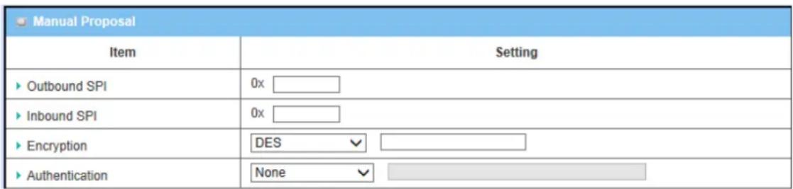
When “Manually” key management is used, there are 4 further parameters need to be specified by you and used in IPSec tunnel establishing.
- Outbound SPI: SPI is an important parameter during hashing. Outbound SPI will be included in the outbound packet transmitted from local gateway. The value of outbound SPI should be set in hex formatted.
- Inbound SPI: Inbound SPI will be included in the inbound packet transmitted from remote VPN peer. It will be used to de-hash the coming packet and check its integrity. The value of inbound SPI should be set in hex formatted.
- Encryption Algorithm: There are five algorithms can be selected: DES, 3DES, AES-128, AES-192, and AES-256. Encryption key is used by the encryption algorithm. Its length is 16 in hex format if encryption algorithm is DES or 48 if 3 DES. However, AES-128 uses 32 length of hex format, AES-192 uses 48 length of hex format, and AES-256 uses 64 length of hex format. The key value should be set in hex formatted here.
- Authentication: There are five algorithms can be selected: None, MD5, SHA1, SHA2-256 and SHA2-512. Authentication key is used by the authentication algorithm and its length is 32 in hex format if authentication algorithm is MD5 or 40 if SHA1. However, SHA2-256 uses 64 length of hex format. Certainly, its length will be 0 if no authentication algorithm is chosen. The key value should be also set in hex formatted.
4.2.3.3 PPTP
The Point-to-Point Tunneling Protocol (PPTP) is a method for implementing virtual private networks. PPTP uses a control channel over TCP and a GRE tunnel operating to encapsulate PPP packets. The PPTP specification does not describe encryption or authentication features and relies on the Point-to-Point Protocol being tunneled to implement security functionality. However, the most common PPTP implementation shipping with the Microsoft Windows product families implements various levels of authentication and encryption natively as standard features of the Windows PPTP stack. The intended use of this protocol is to provide security levels and remote access levels comparable with typical VPN products.
4.2.3.3.1 PPTP / L2TP VPN Tunnel Scenarios
There are some common PPTP/L2TP VPN connection scenarios as follows:
- PPTP / L2TP Server for Remote Mobile Users
The device acts as Server role for remote users to dial in and shares some services in Intranet for them.
• PPTP / L2TP Server / Client Application
The device acts as Server or Client role in SMB Headquarters or Branch Office.
The Business Security Gateway can behave as a PPTP server and a PPTP client at the same time.
![Configuration IPSec PPTP L2TP GRE Configuration [ Help ] Item Setting PPTP Enable Client/Server Server ▼ PPTP Server Configuration Item Setting PPTP Server Enable Server Virtual IP 192.168.0.1 IP Pool Starting Address 10 IP Pool Ending Address 100 Authentication Protocol PAP CHAP MS-CHAP MS-CHAP v2 MPPE Encryption Enable 40 bits ▼ PPTP Server Status Refresh User Name Remote IP Remote Virtual IP Remote Call ID Actions No connection from remote User Account List Add Delete ID User Name Password Enable Actions](/content/2026/05/914011/images/e01d95c534d757a5ed5285e0850f9963a96753b608cb0d65e330c9610620633e.jpg)
- PPTP: Check the "Enable" box to activate PPTP client and server functions.
Client/Server: Choose Server or Client to configure corresponding role of PPTP VPN tunnels for the Business Security Gateway beneath the choosing screen
4.2.3.3.2 PPTP Server Configuration
The Business Security Gateway can behave as a PPTP server, and it allows remote hosts to access LAN servers behind the PPTP server. The device can support four authentication methods: PAP, CHAP, MS-CHAP and MS-CHAP v2. Users can also enable MPPE encryption when using MS-CHAP or MS-CHAP v2.

-
PPTP Server: Enable or disable PPTP server function.
-
Server Virtual IP: It is the virtual IP address of PPTP server used in PPTP tunneling. This IP address should be different from the gateway one and members of LAN subnet of Business Security Gateway.
- IP Pool Starting Address: This device will assign an IP address for each remote PPTP client. This value indicates the beginning of IP pool.
- IP Pool Ending Address: This device will assign an IP address for each remote PPTP client. This value indicates the end of IP pool.
- Authentication Protocol: You can choose authentication protocol as PAP, CHAP, MS-CHAP, or MS-CHAP v2.
- MPPE Encryption: Check the "Enable" box to activate MPPE encryption. Please note that MPPE needs to work with MS-CHAP or MS-CHAP v2 authentication method. In the meantime, you also can choose encryption length of MPPE encryption, 40 bits, 56 bits or 128 bits.
4.2.3.3.3 PPTP Server Status
The user name and connection information for each connected PPTP client to the PPTP server of the Business Security Gateway will be shown in this table.
| PPTP Server Status Refresh | ||||
| User Name | Peer IP | Virtual IP | Peer Call ID | Actions |
| test | 192.168.12.106 | 192.168.0.10 | 6034 | Disconnect |
-
Refresh: To refresh the PPTP Server Status each 2 seconds by clicking on the "Refresh" button.
-
Disconnect: To terminate the connection between PPTP server and remote dialing in PPTP clients by clicking on the "Disconnect" button.
4.2.3.3.4 User Account List
You can input up to 10 different user accounts for dialing in PPTP server.
| User Account List Add Delete | ||||
| ID | User Name | Password | Account | Actions |
| 1 | test | test | Enable | Edit Select |
-
Add: You can add one new user account by clicking on the "Add" button.
-
Delete: Delete selected user accounts by checking the "Select" box at the end of each user account list and then clicking on the "Delete" button.
-
Account: Check the "Enable" box to validate the user account.
-
Edit: You can edit one user account configuration by clicking on the "Edit" button at the end of each user account list.
4.2.3.3.5 User Account Configuration
Add or edit one user account will activate the "User Account Configuration" screen.
| User Account Configuration | ||
| User Name | Password | Account |
| AMIT | tima | ☑ |
| save | ||
-
User Name: Enter the user name of user account.
-
Password: Enter the password of user account.
-
Account: Check the "Enable" box to validate the user account.
-
Save: To save the user account configuration.
4.2.3.3.6 PPTP Client
The Business Security Gateway also can behave as a PPTP client except PPTP server, and PPTP client tries to establish a PPTP tunnel to remote PPTP server. All client hosts in the Intranet of Business Security Gateway can access LAN servers behind the PPTP server.
| PPTP Client Configuration | |
| Item | Setting |
| PPTP Client | Enable |
- PPTP Client: Enable or disable PPTP client function.
4.2.3.3.7 PPTP Client List & Status
You can add new up to 22 different PPTP client tunnels by clicking on the "Add" button, and modify each tunnel configuration by clicking on the corresponding "Edit" button at the end of each existed tunnel.
| PPTP Client List & Status Add Delete | |||||||
| ID | PPTP Client Name | Virtual IP | RemoteIP/FQDN | Default Gateway/Peer Subnet | Status | Tunnel | Actions |
| 1 | PPTP_Tunnel | 192.168.0.11 | 192.168.0.1 | 0.0.0.0/0 | Connected | Enable | Edit Select |
-
Add: You can add one new PPTP client tunnel by clicking on the "Add" button.
-
Delete: Delete selected tunnels by checking the "Select" box at the end of each tunnel list and then clicking on the "Delete" button.
- Tunnel: Check the "Enable" box to activate the tunnel.
- Edit: You can edit one PPTP client tunnel configuration by clicking on the "Edit" button at the end of each tunnel list.
4.2.3.3.8 PPTP Client Configuration
![Configuration > IPSec > PPTP > L2TP > GRE Configuration [ Help ] Item Setting PPTP Enable Client/Server Server PPTP Server Configuration Item Setting PPTP Server Enable Server Virtual IP 192.168.0.1 IP Pool Starting Address 10 IP Pool Ending Address 100 Authentication Protocol PAP CHAP MS-CHAP MS-CHAP v2 MPPE Encryption Enable 40 bits PPTP Server Status Refresh User Name Remote IP Remote Virtual IP Remote Call ID Actions No connection from remote User Account List Add Delete ID User Name Password Enable Actions](/content/2026/05/914011/images/cd1bb2edfd15094836d8d996c450b801477756d0fad958ab934c6b45dc00d240.jpg)
- PPTP Client Name: The name of this tunnel.
- Operation Mode: Default is "Always on" and other options depend on product models.
- Peer IP/Domain: The IP address or Domain name of remote PPTP server.
- User Name: The username which can be validated by remote PPTP server.
- Password: The password which can be validated by remote PPTP server.
-
Default Gateway/Peer Subnet: You can choose "Default Gateway" option or "Peer Subnet" option here. When "Default Gateway" is chosen, all traffic from Intranet of Business Security Gateway goes over this PPTP tunnel if these packets don't match the Peer Subnet of other PPTP tunnels. There is only one PPTP tunnel to own the "Default Gateway" property. However, when "Peer Subnet" is chosen, peer subnet parameter needs to be filled and it should be the LAN subnet of remote PPTP server. If an Intranet packet wants to go to this peer subnet, the PPTP tunnel will be established automatically.
-
Connection Control: There are three connection control options for users to choose when the PPTP tunnel is established. You can choose "Connect-on-Demand", "Auto Reconnect(always-on)", or "Manually". By default, it is "Auto Reconnect(always-on)".
-
Authentication Protocol: You can choose authentication protocol as PAP, CHAP, MS-CHAP, or MS-CHAP v2. The protocol you choose must be supported by remote PPTP server.
-
MPPE Encryption: Check the "Enable" box to activate MPPE encryption. Please note that MPPE needs to work with MS-CHAP or MS-CHAP v2 authentication methods.
-
NAT before Tunneling: Check the "Enable" box to let hosts in the Intranet of Business Security Gateway can go to access Internet via remote PPTP server. By default, it is enabled. However, if you want the remote PPTP Server to monitor the Intranet of local Business Security Gateway, the option can't be enabled.
-
LCP Echo Type: Choose the way to do connection keep alive. By default, it is "Auto" option that means system will automatically decide the time interval between two LCP echo requests and the times that system can retry once system LCP echo fails. You also can choose "User-defined" option to define the time interval and the retry times by yourself. The last option is "Disable".
-
Tunnel: Check the "Enable" box to activate the tunnel.
4.2.3.4 L2TP
In computer networking, Layer 2 Tunneling Protocol (L2TP) is a tunneling protocol used to support virtual private networks(VPNs) or as part of the delivery of services by ISPs. It does not provide any encryption or confidentiality by itself. Rather, it relies on an encryption protocol that it passes within the tunnel to provide privacy.
The Business Security Gateway can behave as a L2TP server and a L2TP client at the same time.
| Configuration | [HELP] | |
| Item | Setting | |
| L2TP | Enable | |
| Client/Server | Server | |
-
L2TP:Check the "Enable" box to activate L2TP client and server functions.
-
Client/Server: Choose Server or Client to configure corresponding role of L2TP VPN tunnels for the Business Security Gateway beneath the choosing screen.
4.2.3.4.1 L2TP Server Configuration
The Business Security Gateway can behave as a L2TP server, and it allows remote hosts to access LAN servers behind the L2TP server. The device can support four authentication methods: PAP, CHAP, MS-CHAP and MS-CHAP v2. Users can also enable MPPE encryption when using MS-CHAP or MS-CHAP v2.
| LZTP Server Configuration | |
| Item | Setting |
| L2TP Server | Enable |
| L2TP over IPsec | Enable Preshare Key(Min. 8 characters) |
| Server Virtual IP | 192.168.10.1 |
| IP Pool Starting Address | 10 |
| IP Pool Ending Address | 100 |
| Authentication Protocol | PAP CHAP MS-CHAP MS-CHAP v2 |
| MPPE Encryption | Enable 40 bits |
-
L2TP Server: Enable or disable L2TP server function.
-
L2TP over IPSec: L2TP over IPSec VPNs allow you to transport data over the Internet, while still maintaining a high level of security to protect data. Enter a Pre-shared key that system will use it in IPSec tunneling. And when you use some devices, like Apple related mobile devices, you should also know that key to establish L2TP over IPSec tunnels.
-
Server Virtual IP: It is the virtual IP address of L2TP server used in L2TP tunneling. This IP address should be different from the gateway one and members of LAN subnet of Business Security Gateway.
-
IP Pool Starting Address: This device will assign an IP address for each remote L2TP client. This value indicates the beginning of IP pool.
-
IP Pool Ending Address: This device will assign an IP address for each remote L2TP client. This value indicates the end of IP pool.
-
Authentication Protocol: You can choose authentication protocol as PAP, CHAP, MS-CHAP, or MS-CHAP v2.
-
MPPE Encryption: Check the "Enable" box to activate MPPE encryption. Please note that MPPE needs to work with MS-CHAP or MS-CHAP v2 authentication method. In the meantime, you also can choose encryption length of MPPE encryption, 40 bits, 56 bits or 128 bits.
4.2.3.4.2 L2TP Server Status
The user name and connection information for each connected L2TP client to the L2TP server of the Business Security Gateway will be shown in this table.
| L2TP Server Status Refresh | ||||
| User Name | Peer IP | Virtual IP | Peer Call ID | Actions |
| test | 192.168.12.106 | 192.168.10.10 | 139911 | Disconnect |
-
Refresh: To refresh the L2TP Server Status each 2 seconds by clicking on the "Refresh" button.
-
Disconnect: To terminate the connection between L2TP server and remote dialing in L2TP clients by clicking on the "Disconnect" button.
4.2.3.4.3 User Account List
You can input up to 10 different user accounts for dialing in L2TP server.
| User Account List Add Delete | ||||
| ID | User Name | Password | Account | Actions |
| 1 | test | test | Enable | Edit Select |
-
Add: You can add one new user account by clicking on the "Add" button.
-
Delete: Delete selected user accounts by checking the "Select" box at the end of each user account list and then clicking on the "Delete" button.
-
Account: Check the "Enable" box to validate the user account.
-
Edit: You can edit one user account configuration by clicking on the "Edit" button at the end of each user account list.
4.2.3.4.4 User Account Configuration
Add or edit one user account will activate the "User Account Configuration" screen.
| User Account Configuration | ||
| User Name | Password | Account |
| AMIT | tima | ☑ |
| save | ||
-
User Name: Enter the user name of user account.
-
Password: Enter the password of user account.
-
Account: Check the "Enable" box to validate the user account.
-
Save: To save the user account configuration.
4.2.3.4.5 L2TP Client
The Business Security Gateway also can behave as a L2TP client except L2TP server, and L2TP client tries to establish a L2TP tunnel to remote L2TP server. All client hosts in the Intranet of Business Security Gateway can access LAN servers behind the L2TP server.
| L2TP Client Configuration | |
| Item | Setting |
| L2TP Client | Enable |
4.2.3.4.6 L2TP Client List & Status
You can add new up to 22 different L2TP client tunnels by clicking on the "Add" button, and modify each tunnel configuration by clicking on the corresponding "Edit" button at the end of each existed tunnel.
| L2TP Client List & Status Add Delete | |||||||
| ID | L2TP Client Name | Virtual IP | Remote IP | Default Gateway/Remote Subnet | Status | Tunnel | Actions |
| 1 | L2TP_Tunnel | 192.168.10.10 | 192.168.10.1 | 0.0.0.0/0 | Connected | Enable | Edit Select |
- Add: You can add one new L2TP client tunnel by clicking on the "Add" button.
- Delete: Delete selected tunnels by checking the "Select" box at the end of each tunnel list and then clicking on the "Delete" button.
- Tunnel: Check the "Enable" box to activate the tunnel.
- Edit: You can edit one L2TP TP client tunnel configuration by clicking on the "Edit" button at the end of each tunnel list.
4.2.3.4.7 L2TP Client Configuration
![User Account Definition for Client [HELP] Item Setting ► L2TP Client Name L2TP_Tunnel ► Operation Mode Always on ► Remote IP/FQDN 192.168.12.109 ► User Namealed funds ► Password ●●●●● ► Default Gateway Default Gateway ▼ 0.0.0.0/0 ► Connection Control Connect-on-demand ► Authentication Protocol ✓ PAP ✓ CHAP ✓ MS-CHAP ✓ MS-CHAP v2 ► MPPE Encryption Enable ► NAT before Tunneling ✓ NAT ► LCP Echo Type Auto Interval 30 seconds Max. Failure Time 6 times ► Tunnel ✓ Enable](/content/2026/05/914011/images/b34fad7e412a00ebffb6783e0941fd94bf15f97543489d8ced71c84de91ffc57.jpg)
- L2TP Client Name: The name of this tunnel.
- Operation Mode: Default is "Always on" and other options depend on product models.
- Peer IP/Domain: The IP address or Domain name of remote L2TP server.
- UserName: The user name which can be validated by remote L2TP server.
- Password: The password which can be validated by remote L2TP server.
- Default Gateway/Peer Subnet: You can choose "Default Gateway" option or "Peer Subnet" option here. When "Default Gateway" is chosen, all traffic from Intranet of Business Security Gateway goes over this L2TP tunnel if these packets don't match the Peer Subnet of other L2TP tunnels. There is only one L2TP tunnel to own the "Default Gateway" property. However, when "Peer Subnet" is chosen, peer subnet parameter needs to be filled and it should be the LAN subnet of remote L2TP server. If an Intranet packet wants to go to this peer subnet, the L2TP tunnel will be established automatically.
- Connection Control: There are three connection control options for users to choose when the L2TP tunnel is established. You can choose "Connect-on-Demand", "Auto Reconnect(always-on)", or "Manually". By default, it is "Auto Reconnect(always-on)".
-
Authentication Protocol: You can choose authentication protocol as PAP, CHAP, MS-CHAP, or MS-CHAP v2. The protocol you choose must be supported by remote L2TP server.
-
MPPE Encryption: Check the "Enable" box to activate MPPE encryption. Please note that MPPE needs to work with MS-CHAP or MS-CHAP v2 authentication methods.
-
NAT before Tunneling: Check the "Enable" box to let hosts in the Intranet of Business Security Gateway can go to access Internet via remote PPTP server. By default, it is enabled. However, if you want the remote PPTP Server to monitor the Intranet of local Business Security Gateway, the option can't be enabled.
-
LCP Echo Type: Choose the way to do connection keep alive. By default, it is "Auto" option that means system will automatically decide the time interval between two LCP echo requests and the times that system can retry once system LCP echo fails. You also can choose "User-defined" option to define the time interval and the retry times by yourself. The last option is "Disable".
-
Tunnel: Check the "Enable" box to activate the tunnel.
4.2.3.5 GRE
Generic Routing Encapsulation (GRE) is a tunneling protocol developed by Cisco Systems that can encapsulate a wide variety of network layer protocols inside virtual point-to-point links over an Internet Protocol internet work.
4.2.3.5.1 GRE VPN Tunnel Scenario
Generic Routing Encapsulation (GRE) is a tunneling protocol developed by Cisco Systems that can encapsulate a wide variety of network layer protocols inside virtual point-to-point links over an Internet Protocol inter network.
4.2.3.5.2 GRE Configuration
There is one common GRE VPN connection scenario as follows:
• GRE Server / Client Application
The Business Security Gateway acts as GRE Server or Client role in SMB Headquarters or Branch Office.
4.2.3.5.3 GRE Tunnel Definition
| GRE Tunnel Definitions Add Delete | ||||||||
| ID | Tunnel Name | Tunnel IP | Peer IP | Key | TTL | Default Gateway/ Peer Subnet | Enable | Actions |
| 1 | 1 | 100.100.1.1 | 200.200.2.2 | 1234 | 255 | 192.168.200.0/24 | Edit | |
- Add: You can add one new GRE tunnel by clicking on the "Add" button.
- Delete: Delete selected tunnels by checking the "Select" box at the end of each tunnel list and then clicking on the "Delete" button.
- Tunnel: Check the "Enable" box to activate the GRE tunnel.
- Edit: You can edit one tunnel configuration by clicking the "Edit" button at the end of each tunnel list.
4.2.3.5.4 GRE rule Configuration
![Configuration IPSec PPTP L2TP GRE Configuration [Help] Item Setting GRE Tunnel Enable GRE Tunnel List Add Delete ID Tunnel Name Interface Operation Mode Tunnel IP Remote IP Key TTL Keep-alive Default Gateway/ Remote Subnet Enable Actions Save Undo](/content/2026/05/914011/images/fe1ae17fe5b1344097e6dcb6339f1baf325fffba2a576c06efda1177e88dc176.jpg)
- Tunnel: Enable or disable this GRE tunnel
- Tunnel Name: The name of this GRE tunnel.
- Tunnel IP: The gateway IP address of Business Security Gateway.
- Peer IP: Enter the IP address of remote peer that you want to connect.
- Key: Enter the password to establish GRE tunnel with remote host.
- TTL: Time-To-Live for packets. The value is within 1 to 255. If a packet passes number of TTL routers and still can't reach the destination, then this packet will be dropped.
- Default Gateway/Peer Subnet: You can choose “Default Gateway” option or “Peer Subnet” option here. When “Default Gateway” is chosen, all traffic from Intranet of Business Security Gateway goes over this GRE tunnel if these packets don’t match the Peer Subnet of other GRE tunnels. There is only one GRE tunnel to own the “Default Gateway” property. However, when “Peer Subnet” is chosen, peer subnet parameter needs to be filled and it should be the LAN subnet of remote GRE server. If an Intranet packet wants to go to this peer subnet, the GRE tunnel will be established automatically.
4.2.4 Redundancy
4.2.4.1 VRRP
The Virtual Router Redundancy Protocol(VRRP) is a computer networking protocol providing device redundancy. It allows a backup router or switch to automatically take over if the primary (master) router or switch fails. This increases the availability and reliability of routing paths via automatic default gateway selections on an IP network.

flowchart
graph TD
    A["Internet Access"] --> B["Host 211.23.11.12"]
    A --> C["Host 118.18.811.33"]
    B --> D["Master: 192.168.12.254"]
    C --> E["Slave: 192.168.12.253"]
    D --> F["VRRP Setting: Virtual Server ID: 1 Priority: 254"]
    D --> G["VRRP Setting: Virtual Server ID: 1 Priority: 253"]
    D --> H["VRRP Setting: Virtual Server ID: 1 Priority: 254"]
    D --> I["VRRP Setting: Virtual Server ID: 1 Priority: 253"]
    D --> J["VRRP Setting: Virtual Server ID: 1 Priority: 254"]
    D --> K["VRRP Setting: Virtual Server ID: 1 Priority: 253"]
    D --> L["VRRP Setting: Virtual Server ID: 1 Priority: 254"]
    D --> M["VRRP Setting: Virtual Server ID: 1 Priority: 253"]
    D --> N["VRRP Setting: Virtual Server ID: 1 Priority: 254"]
    D --> O["VRRP Setting: Virtual Server ID: 1 Priority: 253"]
    D --> P["VRRP Setting: Virtual Server ID: 1 Priority: 254"]
    D --> Q["VRRP Setting: Virtual Server ID: 1 Priority: 253"]
    D --> R["VRRP Setting: Virtual Server ID: 1 Priority: 254"]
    D --> S["VRRP Setting: Virtual Server ID: 1 Priority: 253"]
    D --> T["VRRP Setting: Virtual Server ID: 1 Priority: 254"]
    D --> U["VRRP Setting: Virtual Server ID: 1 Priority: 253"]
    D --> V["VRRP Setting: Virtual Server ID: 1 Priority: 254"]
    D --> W["VRRP Setting: Virtual Server ID: 1 Priority: 253"]
    D --> X["VRRP Setting: Virtual Server ID: 1 Priority: 254"]
    D --> Y["VRRP Setting: Virtual Server ID: 1 Priority: 253"]
    D --> Z["VRRP Setting: Virtual Server ID: 1 Priority: 254"]
    D --> AA["VRRP Setting: Virtual Server ID: 1 Priority: 253"]
    D --> AB["VRRP Setting: Virtual Server ID: 1 Priority: 254"]
    D --> AC["VRRP Setting: Virtual Server ID: 1 Priority: 253"]
    D --> AD["VRRP Setting: Virtual Server ID: 1 Priority: 254"]
    D --> AE["VRRP Setting: Virtual Server ID: 1 Priority: 253"]
    D --> AF["VRRP Setting: Virtual Server ID: 1 Priority: 254"]
    D --> AG["VRRP Setting: Virtual Server ID: 1 Priority: 253"]
    D --> AH["VRRP Setting: Virtual Server ID: 1 Priority: 254"]
    D --> AI["VRRP Setting: Virtual Server ID: 1 Priority: 253"]
    D --> AJ["VRRP Setting: Virtual Server ID: 1 Priority: 254"]
    D --> AK["VRRP Setting: Virtual Server ID: 1 Priority: 253"]
    D --> AL["VRRP Setting: Virtual Server ID: 1 Priority: 254"]
    D --> AM["VRRP Setting: Virtual Server ID: 1 Priority: 253"]
    D --> AN["VRRP Setting: Virtual Server ID: 1 Priority: 254"]
    D --> AO["VRRP Setting: Virtual Server ID: 1 Priority: 253"]
    D --> AP["VRRP Setting: Virtual Server ID: 1 Priority: 254"]
    D --> AQ["VRRP Setting: Virtual Server ID: 1 Priority: 253"]
    D --> AR["VRRP Setting: Virtual Server ID: 1 Priority: 254"]
    D --> AS["VRRP Setting: Virtual Server ID: 1 Priority: 253"]
    D --> AT["VRRP Setting: Virtual Server ID: 1 Priority: 254"]
    D --> AU["VRRP Setting: Virtual Server ID: 1 Priority: 253"]
    D --> AV["VRRP Setting: Virtual Server ID: 1 Priority: 254"]
    D --> AW["VRRP Setting: Virtual Server ID: 1 Priority: 253"]
    D --> AX["VRRP Setting: Virtual Server ID: 1 Priority: 254"]
The protocol achieves this by creation of virtual routers, which are an abstract representation of multiple routers, i.e. master and back up routers, acting as a group. The default gateway of a participating host is assigned to the virtual router instead of a physical router. If the physical router that is routing packets on behalf of the virtual router fails, another physical router is selected to automatically replace it. The physical router that is forwarding packets at any given time is called the master router.

-
VRRP: Enable or disable the VRRP function.
-
Virtual Server ID: Means Group ID. Specify the ID number of the virtual server. Its value ranges from 1 to 255.
-
Priority of Virtual Server: Specify the priority to use in VRRP negotiations. Valid values are from 1 to 254, and a larger value has higher priority.
-
Virtual Server IP Address: Specify the IP address of the virtual server.
Click on "Save" to store what you just select or "Undo" to give up.
4.2.5 System Management
This device supports many system management protocols, such as TR-069, SNMP, Telnet with CLI and UPnP. You can finish those configurations in this sub-section.
![TR-069 > SNMP > Telnet with CLI > UPnP Configuration [ Help ] Item Setting TR-069 Enable Interface WAN-1 ACS URL ACS UserName ACS Password ConnectionRequest Port 8099 ConnectionRequest UserName ConnectionRequest Password Inform Enable Interval 800 Save Undo Basic Network Advanced Network Firewell QoS & BWM VPN Redundancy System Management Certificate Applications System](/content/2026/05/914011/images/508c4e8ff047c2330f699abed541f017911d7f5edfe5e631a6dc15b413533864.jpg)
Forum Technical
4.2.5.1 TR--069
TR-069(Technical Report 069) is a Broadband Forum technical specification entitled CPE WAN Management Protocol(CWMP). It defines an application layer protocol for remote management of end-user devices, like this gateway device. As a bidirectional SOAP/HTTP-based protocol, it provides the communication between customer-premises equipment (CPE) and Auto Configuration Servers (ACS). The Security Gateway is such CPE.
![TR-069 SNMP Telnet with CLI UPnP Configuration [ Help ] Item Setting TR-069 Enable Interface WAN-1 ACS URL ACS Username ACS Password ConnectionRequest Port 8099 ConnectionRequest UserName ConnectionRequest Password Inform Enable Interval 800 Save Undo](/content/2026/05/914011/images/8fda415d493c636adeff201c87b785825811e382a54e2d9ae4b128363ad80463.jpg)
TR-069 is a customized feature for ISP; it is not recommend that you change the configuration for this. If you have any problem in using this feature for device management, please contact you're your ISP or the ACS provider for help. At the right upper corner of TR-069 Setting screen, one "[Help]" command let you see the same message about that.
4.2.5.2 SNMP
In brief, SNMP, the Simple Network Management Protocol, is a protocol designed to give a user the capability to remotely manage a computer network by polling and setting terminal values and monitoring network events.
In typical SNMP uses, one or more administrative computers, called managers, have the task of monitoring or managing a group of hosts or devices on a computer network. Each managed system executes, at all times, a software component called an agent which reports information via SNMP to the manager.
SNMP agents expose management data on the managed systems as variables. The protocol also permits active management tasks, such as modifying and applying a new configuration through remote modification of these variables. The variables accessible via SNMP are organized in hierarchies. These hierarchies, and other metadata (such as type and description of the variable), are described by Management Information Bases(MIBs).
The device supports several public MIBs and one private MIB for the SNMP agent. The supported MIBs are as follow:
- Supported MIBs
• MIB-II (RFC 1213, Include IPv6)
- IF-MIB, IP-MIB, TCP-MIB, UDP-MIB
- SMIv1 and SMIv2
• SNMPv2-TM and SNMPv2-MIB
• AMIB (AirLive Private MIB)
| Configuration [ Help ] | |
| Item | Setting |
| SNMP Enable | LAN WAN |
| Supported Versions | v1 v2c v3 |
| Get / Set Community | ReadC / WriteC |
| Trap Event Receiver 1 | 192.168.123.10 |
| Trap Event Receiver 2 | |
| Trap Event Receiver 3 | |
| Trap Event Receiver 4 | |
| WAN Access IP Address | 192.168.123.10 |
- SNMP Enable: You can check "Local(LAN)", "Remote(WAN)" or both to enable SNMP function. If "Local(LAN)" is checked, this device will respond to the request from LAN. If "Remote (WAN)" is checked, this device will respond to be request from WAN.
- WAN Access IP Address: If you want to limit the remote SNMP access to specific computer, please enter the PC's IP address. The default value is 0.0.0.0, and it means that any internet connected computer can get some information of the device with SNMP protocol.
- SNMP Version: Supports SNMP V1 and V2c.
- Get Community: The community of Get Request that this device will respond. This is a text password mechanism that is used to weakly authenticate queries to agents of managed network devices.
- Set Community: The community of Set Request that this device will accept.
- Trap Event Receiver 1\~4: Enter the IP addresses or Domain Name of your SNMP Management PCs. You have to specify it, so that the device can send SNMP Trap message to the management PCs consequently.
- WAN Access IP Address: The IP address of remote control site to manage the device by using SNMP protocol.
A User Privacy table is used for only SNMPv3. It defines the user list and their privacy and authority settings.
| User Privacy Definition | |||||||||
| ID | User Name | Password | Authentication | Encryption | Privacy Mode | Privacy Key | Authority | Enable | Actions |
| 1 | User1 | Password1 | MD5 √ | DES √ | authNoPriv √ | ReadRead/Write | √ | Edit | |
| 2 | User2 | Password2 | MD5 √ | DES √ | authPriv √ | 1234567890 | ReadRead/Write | √ | Edit |
| 3 | User3 | MD5 √ | DES √ | noAuthNoPriv √ | ReadRead/Write | √ | Edit | ||
| 4 | MD5 | Disable | authNoPriv | Disable | Read | ☐ | Edit | ||
| 5 | MD5 | Disable | authNoPriv | Disable | Read | ☐ | Edit | ||
-
User Name: Input the name for a user.
-
Password & Authentication: Input the password for a user and choose the hashing algorithm for authentication. However, they will not be necessary when you choose the privacy mode to be "no Auth Priv" for the user account.
-
Privacy Mode: Choose the privacy mode for the specific user. There are three options, "no Auth No Priv", "auth No Priv" and "auth Priv".
-
Privacy Key & Encryption: Input the privacy key for a user and choose the encryption algorithm for security.
-
Authority: Specify the Read or Write authority for the user account.
-
Enable: To activate the user account by checking the Enable box.
Afterwards, click on "Save" to store your settings or click "Undo" to give up the changes.
4.2.5.3 Telnet CLI
A command-line interface(CLI), also known as command-line user interface, console user interface, and character user interface (CUI), is a means of interacting with a computer program where the user(or client) issues commands to the program in the form of successive lines of text (command lines). The interface is usually implemented with a command line shell, which is a program that accepts commands as text input and converts commands to appropriate operating system functions. Programs with command-line interfaces are generally easier to automate via scripting. The device supports both Telnet and SSH CLI with default service port 23 and 22, respectively. And it also accepts commands from both LAN and WAN sides.

4.2.5.4 UPnP
UPnP Internet Gateway Device (IGD) Standardized Device Control Protocol is a NAT port mapping protocol and is supported by some NAT routers. It is a common communication protocol of automatically configuring port forwarding. Applications using peer-to-peer networks, multiplayer gaming, and remote assistance programs need away to communicate through home and business gateways. Without IGD one has to manually configure the gateway to allow traffic through, a process which is error prone and time consuming.
![TR-069 SNMP Telnet with CLI UPnP Configuration [Help] Item Setting UPnP Enable Save Undo](/content/2026/05/914011/images/c043fe9ddf2527a43516073add79ab75d30240e94f574fd66243287148da6404.jpg)
This device supports the UPnP Internet Gateway Device(IGD) feature. By default, it is disabled.
4.2.6 Certificate
In cryptography, a public key certificate(also known as a digital certificate or identity certificate) is an electronic document used to prove ownership of a public key. The certificate includes information about the key, information about its owner's identity, and the digital signature of an entity that has verified the certificate's contents are correct. If the signature is valid, and the person examining the certificate trusts the signer, then they know they can use that key to communicate with its owner.
In atypical public-key infrastructure(PKI) scheme, the signer is a certificate authority(CA), usually a company such as VeriSign which charges customers to issue certificates for them. In a web of trust scheme, the signer is either the key's owner(a self-signed certificate) or other users ("endorsements") whom the person examining the certificate might know and trust. The device also plays as a CA role.
Certificates are an important component of Transport Layer Security (TLS, sometimes called by its older name SSL), where they prevent an attacker from impersonating a secure website or other server. They are also used in other important applications, such as email encryption and code signing. Here, it can be used in IPSec tunneling for user authentication.
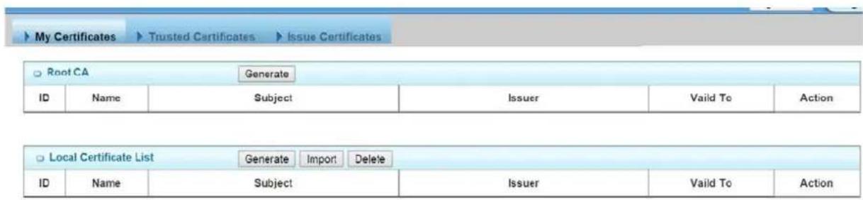
4.2.6.1 My Certificate
My Certificates include Root CA and Local Certificate List. Root CA is the top-most certificate of the tree, the private key of which is used to "sign" other certificates.
Local Certificate is generated in this router. It can be self-signed by its Root CA or just generate a Certificate Signing Request(CSR) which can be signed by another external Root CA.

4.2.6.1.1 Root CA
The device can serve as the Root CA. Root CA can sign local certificate when generate by selected self-signed or the Certificate Signing Request(CSR).

You can generate it by clicking on the "Generate" button.
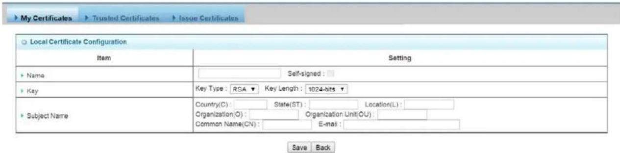
- Name: Enter the name of root CA.
- Key: Key Type is RSA. Key length: The size of the private key in bits. There are five key length can be selected: 512-bits, 765-bits, 1024-bits, 1536-bits, 2048-bits.
- Subject Name: The Subject Name include seven information. Country(C): The two character country code of the certificate authority is located. State(ST): The state where the certificate authority is located. Location(L): The city where the certificate authority is located.
Organization(O): The company whom the certificate authority belongs to. Organization Unit(OU): The company department whom the certificate authority belongs to. Common Name(CN): The common name for certificate authority. It's important as the common name for certificate authority. E-mail: The email address of a contact for the certificate authority.
- Validity: The expiration date. There are four time period can be selected: 3-years, 5-years, 10-years, 20-years.
After successful generating the root CA, you also can delete it by checking the Select box and clicking on the "Delete" button.
You also can view its PEM codes by checking the "View" button.
You can download the local certificate file by clicking on the "Download" button.
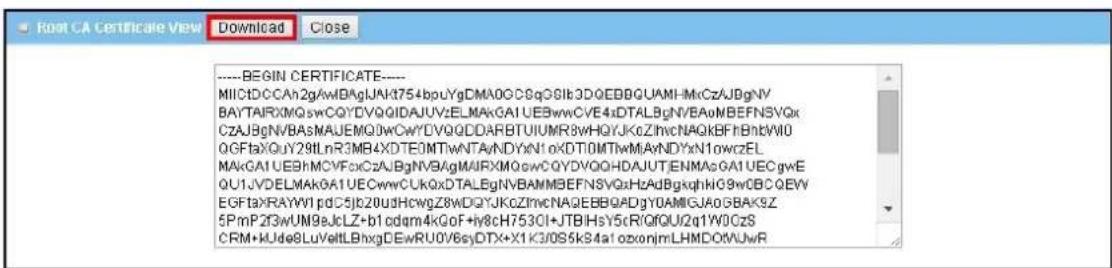
4.2.6.1.2 Local Certificate List
This feature can show the list of all certificates which contain information identifying the applicant. Each certificate involves field of the certificate name, subject, issuer and valid to.
You can generate one certificate by clicking on the "Generate" button.

Save Back
-
Name: Enter the name of certificate.
-
Key: Key Type is RSA. Key length: The size of the private key in bits. There are five key length can be selected: 512-bits, 765-bits, 1024-bits, 1536-bits, 2048-bits.
-
Subject Name: The Subject Name include seven information. Country(C): The two character country code of the certificate is located. State(ST): The state where the certificate is located. Location(L): The city where the certificate is located. Organization(O): The company whom the certificate belongs to. Organization Unit(OU): The company department whom the certificate belongs to. Common Name(CN): The common name for certificate. It's important as the common name for certificate. E-mail: The email address of a contact for the certificate.
You also can import one certificate you're your back up ones by clicking on the "Import" button. There are two approaches to import it. One is from a file and another is copy-paste the PEM codes in Web UI, and then click on the "Apply" button.

Certainly, you also can delete one local certificate by checking corresponding Select box and clicking on the "Delete" button.
You can view its PEM codes by checking the "View" button.
You can download the local certificate file by clicking on the "Download" button.
4.2.6.2 Trusted Certificate
Trusted Certificates include Trusted CA Certificate List and Trusted Client Certificate List. The Trusted CA Certificate List which places the external trusted CA. The Trusted Client Certificate List which place the certificates what you trust.

4.2.6.2.1 Trusted CA Certification List
The device can let you import the certificate of trusted external CA by clicking on the "Import" button.

There are two approaches to import it. One is from a file and another is copy-paste the PEM codes in Web UI, and then click on the "Apply" button.

After successful importing the trusted external CA, you also can delete it by checking the Select box and clicking on the "Delete" button.

You can view its PEM codes by checking the "View" button.
| Trusted CA Certificate List Import Delete | |||||
| ID | Name | Subject | Issuer | Valid To | Action |
| 1 | STARTCOM.cer | /C=IL/O=StartCom Ltd./OU=Secure Digital Certificate Signing/CN=StartCom Certification Authority | /C=IL/O=StartCom Ltd./OU=Secure Digital Certificate Signing/CN=StartCom Certification Authority | Sep 17 19:46:36 2036 GMT | View Select |
You can download the trusted CA file by clicking on the "Download" button.
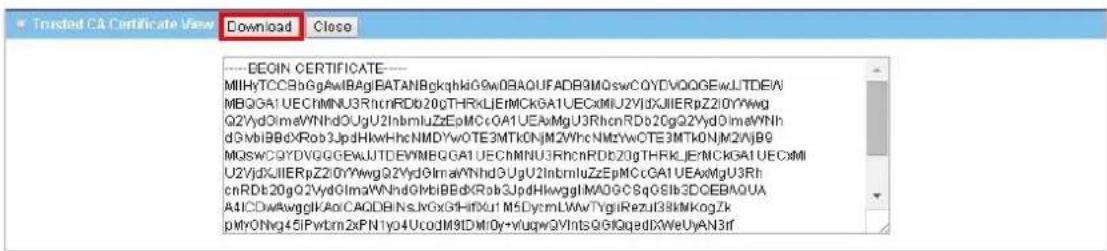
4.2.6.2.2 Trusted Client Certification List
This feature can show the list of all certificates information. Each Certificate involve field of certificate name, subject, issuer and valid to.

You can import one trusted external client certificate by clicking on the "Import" button.

There are two approaches to import it. One is from a file and another is copy-paste the PEM codes in Web UI, and then click on the "Apply" button.
You also can delete one trusted client certificate by checking corresponding Select box and clicking on the "Delete" button.

You can view its PEM codes by checking the "View" button.

You can download the trusted client certificate file by clicking on the "Download" button.

4.2.6.3 Issue Certificates
When you have a Certificate Signing Request (CSR) that needs to be certificated by the root CA of the device, you can issue the request here and let Root CA sign it. There are two approaches to issue it. One is from a file and another is copy-paste the CSR codes in Web UI, and then click on the "Sign" button.
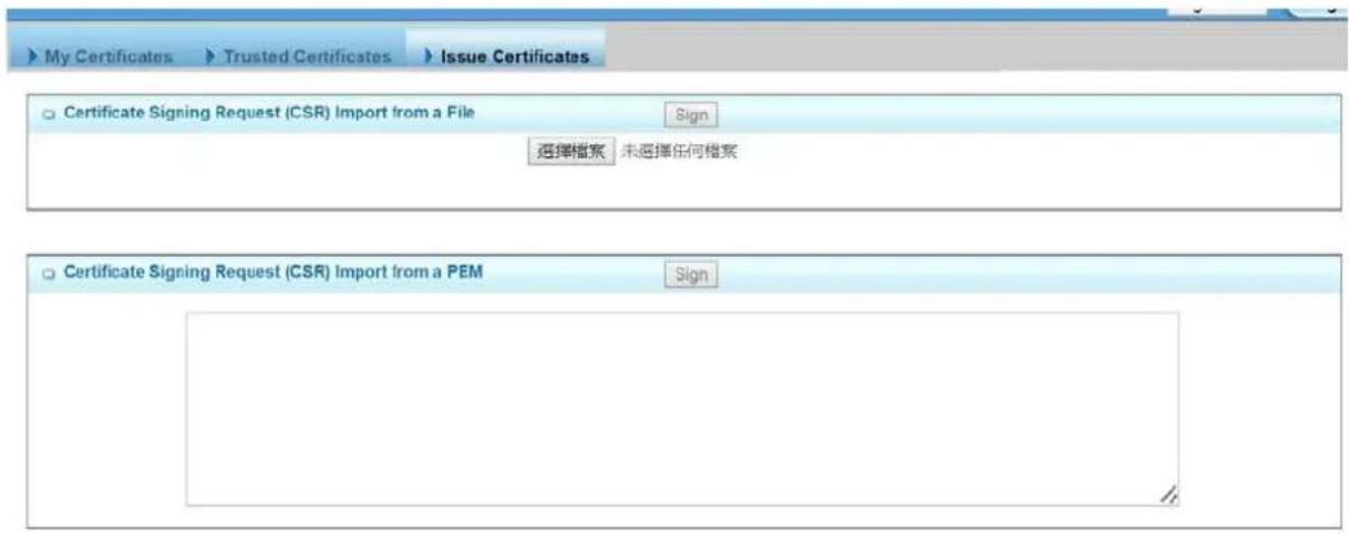
After signing, the Issuer information can be show which is Root CA subject.
| Root CA Delete | |||||
| ID | Name | Subject | Issuer | Vaild To | Action |
| 1 | sam | /C=tw/ST=tw/L=Taipei/O=AirLive/OU=Product/C N=sammy/emailAddress=sammy.chiu@airlive.com | /C=tw/ST=tw/L=Taipei/O=AirLive/OU=Product/C N=sammy/emailAddress=sammy.chiu@airlive.com | Aug 28 06:42:09 2025 G MT | View Select |
You also can view its PEM codes by checking the "View" button and download the issued certificate file by clicking on the "Download" button.

4.3 Application
In this section you can finish the Mobile Application and Captive Portal settings. For Mobile Application, this device is equipped with a 3G/4G module as WAN interface, and it also provide the SMS, USSD, Network Scan, and Remote Management by SMS. Besides, it also serves as an Internet access gateway. Any client host in the Intranet wants to surf the Internet, the device will redirect the Internet surfing request to an external captive portal Web server for user authentication. If the authentication is successful, the requested client host will be allowed to access Internet by the device.

4.3.1 Mobile Application
4.3.1.1 SMS
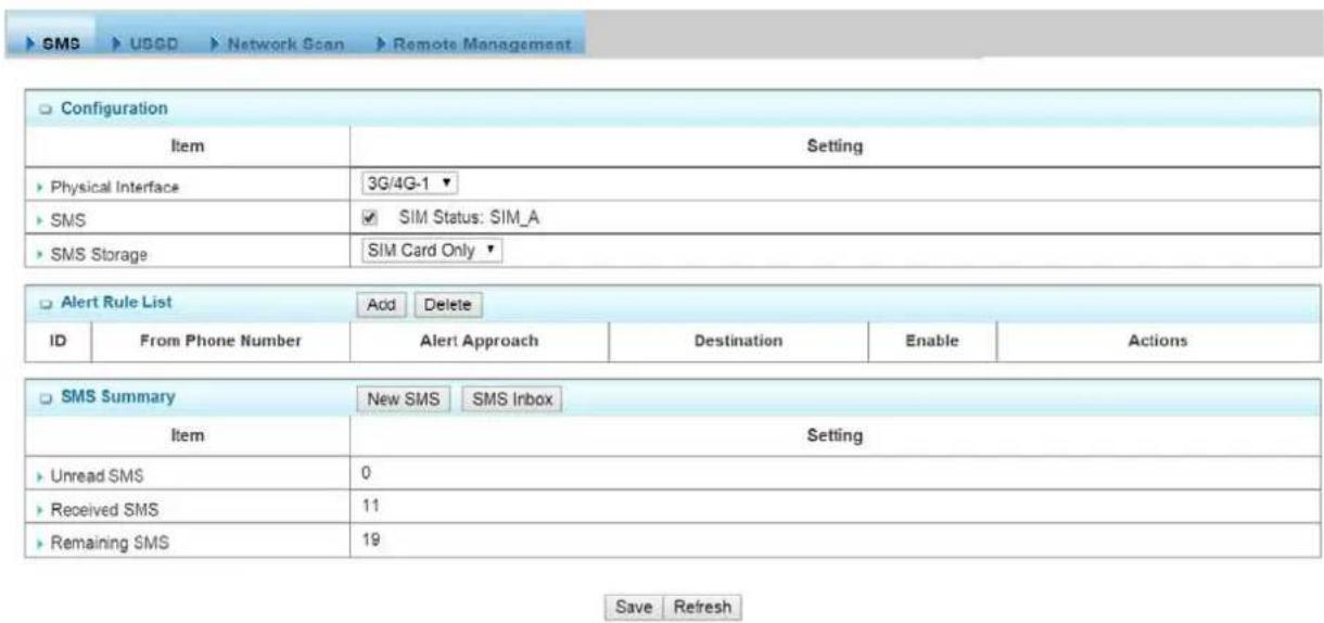
You can compose new SMS message and check received SMS message on this gateway.
| Configuration | |
| Item | Setting |
| Physical Interface | 3G/4G-1 |
| SMS | SIM Status: |
| SMS Storage | SIM Card Only |
- Physical Interface: Indicate which 3G/LTE modem is used for SMS feature.
- SMS: Indicate which SIM card is used for SMS feature.
- SMS Storage: Selects to rage for SMS message. This gateway only supports "SIM Card Only" for SMS storage.
This gateway can forward received SMS message automatically. Press "Add" to add new rule.

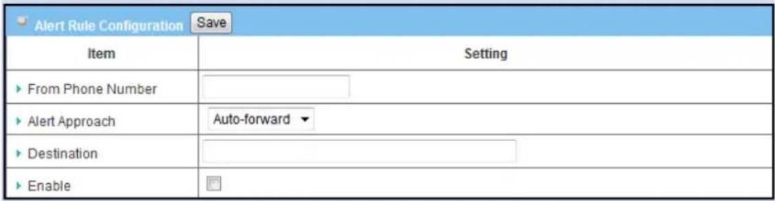
- From Phone Number: Indicate phone number of sender.
- Alert Approach: Decide the way to forward message. You can forward this message to another phone number, or to a mail address, or to a syslog server.
- Destination: Please enter the phone number of receiver if you choose "Auto-forward". Or enter a mail address if choosing "By Email". Or enter the IP address of syslog server if choosing "By Syslog".
- Enable: Enable this rule.
SMS Summary
| SMS Summary New SMS SMS Inbox | |
| Item | Setting |
| ▸ Unread SMS | 0 |
| ▸ Received SMS | 0 |
| ▸ Remaining SMS | 0 |
- Unread SMS: Indicate number of unread SMS message.
- Received SMS: Indicate number of total received SMS message.
- Remaining SMS: Indicate number of new message can be received because of SMS storage limit.
Create New SMS Message
You can create a new SMS message on this page. After finishing the content of message, and filling with phone number of receiver(s), you can press the "Send" button to send this message out. You can see "Send OK" if the new message has been sent successfully.
| New SMS Send | |
| Item | Setting |
| ▶ Receivers | (Use '+' for International Format and '-' to Compose Multiple Receivers) |
| ▶ Text Message | Length of Current Input: 0 |
| ▶ Result | |
Read New SMS Message
You can read, delete, reply, and forward messages in this inbox section.

-
Refresh: You can press "Refresh" button to renew SMS lists.
-
Delete, Reply, Forward Messages: After reading message, you can check the check box on the right of each message to delete, reply, or forward this message.
4.3.1.2 USSD
Unstructured Supplementary Service Data (USSD) is a protocol used by GSM cellular telephones to communicate with the service provider's computers. USSD can be used for prepaid callback service, mobile-money services, location-based content services, and as part of configuring the phone on the network.

USSD Configuration
You can compose a USSD message, and sends it to the service provider, where it is received by a computer dedicated to USSD. The answer from this computer is sent back to this device, but it is usually with a very basic presentation.

- Physical Interface: Indicate which 3G/LTE modem is used for USSD feature. And SIM Status indicates which SIM card is used for USSD feature.
USSD Profile List
You can edit USSD profile for some common used command. Press "Add" button to add new profile. And select some existed profiles to delete by clicking on "Delete" button.

USSD Profile Configuration

-
Profile Name: Indicate name of this profile.
-
USSD Command: Type USSD command of this profile.
3. Comments: Add comments for this profile.
Send USSD Command

You can select USSD command from existed profile or type command manually. Then press "Send" button to send out USSD command.
This part is for 3G/LTE cellular network scan. Usually, this part would be done automatically. Manual scan is used for problem diagnosis.
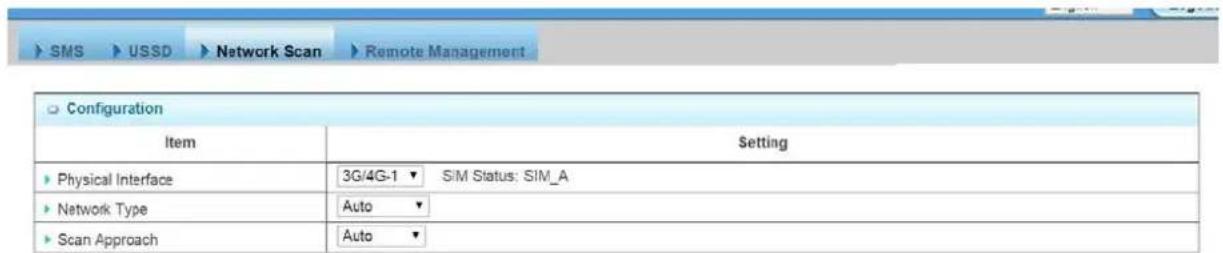
Save
- Physical Interface: Indicate which 3G/LTE modem is used for network scan. And SIM Status indicates which SIM card is used to Network Scan.
- Network Type: Set network type of network scan. You can choose "2G Only", "3G Only", "LTE Only", or "Auto".
- Scan Approach: You can choose "Auto" or "Manually". If you choose "Manually", press "Scan" button to scan cellular network nearby in your environment and select one network provider to apply by clicking on the "Apply" button.

Note Incorrect setting here may cause 3G/LTE connection problems.
4.3.1.4 Remote Management
This part is for remote management functions that are done by text SMS(Short Message Service). Users can send certain SMS to this gateway to activate some actions, such as connect/disconnect/reconnect WAN connection or reboot the system.
Besides, gateway can also send SMS to users to alert some events automatically.
| Management Settings | |
| Item | Setting |
| Remote Management via SMS | Enable Disable |
| Delete SMS for Remote Management | Enable Disable |
| Security Key | |
| Command Settings | |
| Item | Setting |
| Status | Enable Disable |
| Connect | Enable Disable |
| Disconnect | Enable Disable |
| Reconnect | Enable Disable |
| Reboot | Enable Disable |
| Notification Settings | |
| Item | Setting |
| WAN Link Up | Enable Disable |
| WAN Link Down | Enable Disable |
| Access Control List | |
| Item | Setting |
| Access Control | Enable Disable |
| Phone 1 | Management Notification |
| Phone 2 | Management Notification |
| Phone 3 | Management Notification |
Management Settings
| Management Settings | |
| Item | Setting |
| ► Remote Management via SMS | ● Enable ○ Disable |
| ► Delete SMS for Remote Management | ● Enable ○ Disable |
| ► Security Key | SKay |
- Remote Management via SMS: Check this to enable this function.
- Delete SMS for Remote Management: This device will delete received SMS message that is for remote management purpose if enabling this option. This option can prevents to rage space of SIM card from being occupied continuously. If SIM storage is full, this gateway can't receive any new SMS.
- Security Key: This security key will be used for authentication when this gateway receives SMS command. Users need to type this key first and then followed by a command. There should be a “blank” between key and command (e.g.1234 reboot). If this field is empty, users just need to type command without adding any key information.
Note. If security key is empty, access control needs to be activated. The security key can be empty if access control is activated.
Command Settings
| Command Settings | |
| item | Setting |
| Status | ● Enable ○ Disable |
| Connect | ● Enable ○ Disable |
| Disconnect | ● Enable ○ Disable |
| Reconnect | ● Enable ○ Disable |
| Reboot | ● Enable ○ Disable |
- Status: Enable it, and you can send command "status" to query WAN connection status. For 3G/LTE WAN, router will send back WAN IP address, network name, network type, and connection time via SMS. For Ethernet WAN, router will send back WAN IP address and connection time via SMS. The content would be similar to following format:
WAN IP:[xxx.xx.xxx.xx]
Network:[carrier name] (for wireless WAN only)
Type:[GPRS, WCDMA, HSPA, HSPA+, LTE] (for wireless WAN only)
Conn. Time:[connection time]
- Connect: Enable it, and you can send command "connect" to start WAN connection.
- Disconnect: Enable it, and you can send command "disconnect" to disconnect WAN connection.
Note. If this gateway receives "disconnect" command from SMS, it won't try to connect a gain no matter WAN connection mode is set to auto-reconnect.
- Reconnect: Enable it, and you can send command "reconnect" to disconnect WAN connection, and start WAN connection again immediately.
- Reboot: Enable it, and you can send command "reboot" to restart router.
**All management commands are not case sensitive**
Notification Settings
| ▶ Notification Settings | |
| Item | Setting |
| ▶ WAN Link Down | ● Enable ○ Disable |
| ▶ WAN Link Up | ● Enable ○ Disable |
| ▶ Secondary WAN Link is Up | ● Enable ○ Disable |
| ▶ Secondary WAN Link is Down | ● Enable ○ Disable |
-
WAN Link Down: Enable it, and this gateway will send a message to users if primary WAN connection is dropped.
-
WAN Link Up: Enable it, and this gateway will send a message to users if WAN connection is established. This message will also include WAN IP address.
-
Secondary WAN is Up: Enable it, and this gateway will send a message to users if secondary WAN is connected. This message will also include WAN IP address.
-
Secondary WAN is Down: Enable it, and this gateway will send a message to users if secondary WAN is disconnected.
Access Control List

-
Access Control: Users can decide which phone number can send commands to this gateway or receive notifications when enable this option.
-
Phone 1\~5: For security concern, this gateway won't deal with the command if that phone number is not in the list even the security key is correct. The phone number must be with the international prefix (i.e.+886939123456). You can also assign specific phone number can send command and / or also can receive notifications.
4.3.2 Captive Portal
Captive Portal Configuration

Save Refresh
The gateway supports the Captive Portal function, including external captive portal. For external captive portable, you must specify external RADIUS(Remote Authentication Dial In User Service) server and external UAM(Universal Access Method) server.
External Captive Portal
Before enabling external Captive Portal function, please go to System >>External Servers to define some external server objects, like RADIUS server and UAM server. Then configure Captive Portal function in this page to specific WAN Interface, select external Authentication Server and UAM Server from the pre-defined external server object list.
NOTE: All Internet Packets will forward to Captive Portal Web site of the gateway when enabled this feature. Please make sure that you had one account and password.
4.3.3 Position Applications
Position applications are usually referred to applications that take benefits from Global Navigation Satellite System (GNSS). GNSS is the infrastructure that allows devices to determine its position, velocity, and time by processing satellites signals from outer space. GNSS includes varieties of satellite systems and Satellite-Based Augmentation Systems (SBAS). SBAS is usually used for improving positioning accuracy. The tables below show 4 major GNSS system in the world, and SBAS system in different areas.
Major GNSS System in the world
| GNSS System Owner | |
| GPS USA | |
| GLONASS Russia | |
| Galileo European Union | |
| BeiDou (COMPASS) China | |
Satellite-Based Augmentation System (SBAS)
| SBAS Area Coverage | |
| EGNOS Europe | |
| WAAS North America | |
| GAGAN India | |
| MSAS Japan | |
Position applications are widely-used by varieties of industrial applications, including Location-Based Services (LBS), Automatic Vehicle Location (AVL), Fleet Management, or assets tracking. However, in most case, GNSS is a one-way communication. That means GNSS-compatible device can only locate its location by receiving GNSS signal, but it can't forward its location data to any other identity through GNSS system. According to this limitation by GNSS system, devices usually need to equip other technology to transmit their location data to back-end server for track or further analysis. Furthermore, as the position applications are more applied on moving objects, a kind of wireless technology would be more suitable to be adopted to transmit location data. Nowadays, thanks to popularity and wide coverage of cellular technology (GSM, 3G, 4G/LTE), transmitting location data to remote center in real time is no longer a hurdle. In addition, the data format of location data is NMEA 0183 compatible, so the back-end server will be easy to interpret the collected location data.
Hereunder are the main features of GNSS function in the VxG In-Vehicle Gateway.

flowchart
graph TD
    A["Operation Center"] --> B["Internet"]
    B --> C["4G"]
    C --> D["LTE"]
    D --> E["VxG Series"]
    E --> F["GPS Satellite"]
    E --> G["GPS Satellite"]
    E --> H["GPS Satellite"]
    E --> I["GALILEO"]
    E --> J["XIONASS"]
    E --> K["Global Positioning"]
    E --> L["LBS or AVL Applications"]
    style A fill:#f9f,stroke:#333
    style B fill:#ccf,stroke:#333
    style C fill:#cfc,stroke:#333
    style D fill:#fcc,stroke:#333
    style E fill:#cff,stroke:#333
    style F fill:#ffc,stroke:#333
    style G fill:#ffc,stroke:#333
    style H fill:#ffc,stroke:#333
    style I fill:#ffc,stroke:#333
    style J fill:#ffc,stroke:#333
    style K fill:#ffc,stroke:#333
    style L fill:#ffc,stroke:#333
- Retrieve GNSS data from satellites and send to remote operation center periodically or save in local storage.
- Global positioning with multiple GNSS systems, including GPS, and optional for GLONASS, Galileo, or BeiDou.
- Mandatory for varieties of LBS (Location-Based Service) applications, such as advertisement, emergent call.
- Easy integration with AVL (Automatic Vehicle Location) applications, for managing fleet of service vehicles.
- Other value-added applications, such as asset tracking, electronic toll collection, intelligent transport system.
The configuration steps include following items.
- Activate GNSS feature in gateway and finish settings of cellular WAN.
- Indicate remote host, time interval, TCP/UDP, and type of GPS data that would be sent.
- Support NMEA 0183 (compatible to 3.0) protocol, and allow customized prefix and suffix.
Configurable GPS data logging on local microSD card storage for route record tracking.
4.3.3.1 GNSS
With GNSS configuration page, you can configure those functions that are mentioned above. Please note the available GNSS features on different models may be different. Please check product datasheet for details.

Configuration
The configuration part includes all parameters of GNSS function.
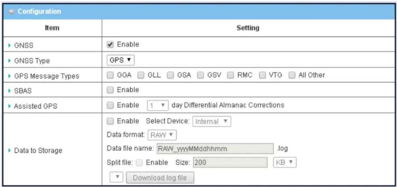
• GNSS
Enable this option if you want to configure and activate GNSS function.
- GNSS Type
There are four major GNSS system (GPS, GLONASS, Galileo, BeiDou) in the world.
| GNSS System Owner | |
| GPS USA | |
| GLONASS Russia | |
| Galileo European Union | |
| BeiDou (COMPASS) China | |
Select a GNSS system that you want to use. Please note this option is hardware dependent. The available options of GNSS type show on this page is according to product specification. You may not see all of these four options in this page if your product doesn't support all of them. Please check product datasheet for details.
- GPS Message Type
This item shows all supported types of NMEA 0183 data format. NMEA 0183 data format was defined and maintained by National Marine Electronics Association (NMEA). Select one or more types that you want to use for transmitting GPS data. In most case, this configuration depends on which data format that your central server can recognize. Only select the type you need, otherwise it will consume unnecessary network bandwidth. The table below shows more information for different types of NMEA 0183 message.
| Type | Description | Example |
| GGA | Fix Information | GPGGA,123519,4807.038,N,01131.000,E,1,08,0.9,545.4,M,46.9,M,*47 |
| GLL | Lat/Lon Data | GPGLL,4916.45,N,12311.12,W,225444,A,*1D |
| GSA | Overall Satellite Data | GPGSA,A,3,04,05,,09,12,,24,,,2.5,1.3,2.1*39 |
| GSV | Detailed Satellite Data | GPGSV,2,1,08,01,40,083,46,02,17,308,41,12,07,344,39,14,22,228,45*75 |
| RMC | Recommended Minimum Data | GPRMC,123519,A,4807.038,N,01131.000,E,022.4,084.4,230394,003.1,W*6A |
| VTG | Vector Track and Speed Over the Ground | GPVTG,054.7,T,034.4,M,005.5,N,010.2,K*48 |
Please note this option is hardware dependent. The available options of GPS message type show on this page is according to product specification. You may not see all options if your product doesn't support all of them. Please check product datasheet for details.
• SBAS
SBAS is Satellite-Based Augmentation Systems that is used to improve accuracy of location data. There are several SBAS systems for different areas in the world.
| SBAS Area Coverage | |
| EGNOS Europe | |
| WAAS North America | |
| GAGAN India | |
| MSAS | Japan |
Please note this option is hardware dependent. You may not see this option if your product doesn't support it. Please check product datasheet for details.
- Assisted GPS
Assisted GPS (as known as A-GPS) is used for speeding up location fix, especially when satellite signal is weak. If activating this option, gateway will download almanac data from A-GPS server through IP network instead of from satellite. You can also choose different valid period of almanac data. The shorter almanac data will get higher accuracy. However, the almanac data with shorter valid period needs to be updated more frequently. It will consume more network bandwidth. Please note this option is hardware dependent. You may not see this option if your product doesn't support it. Please check product datasheet for details.
- Data to Storage
Besides transmitting location data to remote server, you can also store location data into internal storage (e.g. microSD card) or external storage (e.g. USB drive) if any. Regarding to data format, either can be NMEA 0183 raw data format or save it as GPX file format. The location data will be saved to a new file if the original file size is bigger than the pre-defined file size. The “Download log file” button allows you to browse all saved log files and download to your personal devices.
Remote Host List
In most cases, there will be one or many backend servers to deal with GPS data that was sent from field devices for management purpose. For example, the fleet management software would combine map info and GPS data to show specific vehicle track on map. With “Remote Host List”, you can add remote hosts that expect to receive GPS data from this device. Or you can delete or edit existed configuration of existed host list.
| Remote Host Configuration | |
| Item | Setting |
| Host Name | |
| Host IP | |
| Protocol Type | TCP ▼ |
| Port Number | |
| Interval(s) | 1 |
| Prefix Message | |
| Suffix Message | |
| Enable | |
- Host Name
Indicate name of this host record. This name is for identification.
- Host IP
Indicate IP address of remote host that GPS data to be sent.
- Protocol Type
Indicate TCP or UDP packet format will be used to encapsulate GPS data. Please note this option needs to match the corresponding configuration on remote hosts.
- Port Number
Indicate port number of TCP or UDP session will be used to send GPS data. Please note this port number needs to match the port number that remote host is listening.
- Interval
Indicate time interval in seconds between two GPS packets from this device. If with less interval, the backend server will get more accurate location data. However, it will also consume more network bandwidth.
- Prefix Message
Besides standard NMEA 0183 data format, you can also add specific information before NMEA 0183 GPS string if your backend server can recognize. For example, you can input the IMEI code of this device here, and then your backend server can recognize this GPS data is sent from this device. You can also leave this field blank.
- Suffix Message
Besides standard NMEA 0183 data format, you can also add specific information after NMEA 0183 GPS string if your backend server can recognize. For example, you can input the IMEI code of this device here, and then your backend server can recognize this GPS data is sent from this device. You can also leave this field blank.
Scenario of location tracking for fleet management
A fleet owner would like to see the locations of his trucks in real time. He also likes to know where his trucks have been passed through with time information. In his operation office, there is a server (IP: 100.100.100.1) which can interpret NMEA RMC data format and shows truck's location and track on map. This server is listening on TCP port 888 to receive NMEA RMC packet from trucks. IMEI number will be added before NMEA RMC data for identification of each truck. Hereunder is the configuration on each truck.
Basic Settings:
| Configuration Path | [Position Applications]-[Configuration] |
| GNSS | Enable |
| GNSS Type | GPS |
| GPS Message Types | RMC |
| SBAS | Enable |
| Assisted GPS | Enable, 1 |
| Data to Storage | Disable |
Settings for Remote Host:
| Configuration Path | [Position Applications]-[Remote Host Configuration] |
| Host Name | Truck-1 |
| Host IP | 100.100.100.1 |
| Protocol Type | TCP |
| Port Number | 888 |
| Interval(s) | 15 |
| Prefix Message | 123456789012345 |
| Suffix Message | [blank] |
| Enable Checkbox | [Checked] |
The GNSS allows user to set the configuration of GNSS, log NMEA data to storage, and send data to remote host.
Ensure GNSS is enabled and saved.
Go to Applications > Position Applications > GNSS Tab
| Configuration | |
| Item | Setting |
| GNSS | Enable |
| GNSS Type | GPS ▼ |
| GPS Message Types | GGA GLL GSA GSV RMC VTG All Other |
| SBAS | Enable |
| Assisted GPS | Enable1 day Differential Almanac Corrections |
| Data to Storage | Enable Select Device: Internal ▼Data format: RAW ▼Data file name: RAW_yyyMMddhhmmSplit file: Enable Size: 200 KB ▼Download log file |
| GNSS Item | Value setting | Description |
| GNSS Enable | The box is unchecked by default | Check Enable box to activate GNSS functions. |
| GNSS Type | GPS is selected by default | Select a GNSS Type (GNSS System) that you want to use. |
| GNSS Message Types | These box is unchecked by default. | Select one or more GNSS Message Types that you want to use for transmitting or recording GPS data.There are many sentences in the NMEA standard for selecting, GGA, GLL, GSA, GSV, RMC and VTG. ALL Other includes DTM, GNS, GRS, GST, |
| ZDA, and GBS sentences. Only select the type you need, otherwise it will consume unnecessary network bandwidth. | ||
| SBAS | The box is unchecked by default | Check Enable box to activate satellite-based augmentation system (SBAS).Note: Some devices do not support this function. |
| Assisted GPS | The box is checked by default | Check Enable box to activate Assisted GPS (A-GPS).Select the duration for downloading the Differential Almanac Corrections data from A-GPS server through IP network.Note: Some devices may not support this function. |
| Data to Storage | The box is unchecked by default | Enable (The box is unchecked by default)Check Enable box to activate data to storage function.Select Device (A Must filled setting)Select Internal or External device to store log data.Data Format (A Must filled setting)Select data format (RAW, or GPX) to store.Data file name(A Must filled setting)Define file name to store.Split EnableCheck Enable box to activate file splitting function.Split Size& UnitDefine file size and unit for log file.Download log fileSelect a log file and Click Download log file to download through Web GUI. If the log format which is specified to download is GPX, we will convert standard GPX format for used. |
| Save | NA | Click the Save button to save the configuration |
4.4 System
In the System section you can check system related information and execute some system operations, define sometime schedule rules, make object grouping, define external server objects and configure the operation parameters on Web UI surfing.
About system related, you can see system related information and system logs, use system tools for system update and do some network tests.
About Scheduling, you can define sometime scheduling rules here to be applied at various applications in the device system. Whatever one application needs a time schedule, like the "Work Hours" is defined as AM 8:00\~PM 5:00 from Monday to Friday, the time schedule object can be defined in the [System] - [Scheduling] section.
About External Servers, you can define some external server objects here to be applied at various applications in the device system. Whatever one application needs
an external server, like a RADIUS server, the external server object can be defined in the [System] - [External Servers] section. These server objects include Email Server objects, Syslog Server objects, RADIUS Server objects, Active Directory Server objects, LDAP Server objects and UAM Server objects.
About MMI(Man-Machine Interface), it means the Web-based GUI. User can set the administrator time out of Web UI surfing during configuring the device by the administrator.

4.4.1 System Related
System Related section includes "Change Password", "System Information", "System Status" and "System Tools". Change Password is to change the password of administrator for configuring the device by using Web UI. System Tools support system time configuration, FW upgrading, system rebooting, system resetting to default, waking on LAN and configuration settings backup. You also can check the system information and system status log here.
![Change Password System Information System Status System Tools Change Password [ Help ] Item Setting Old Password New Password New Password Confirmation Save Undo](/content/2026/05/914011/images/792e3c1909f3b8bd0d449e0030854a1432e6cde26c8a2d798b40b67d9856ded9.jpg)
4.4.1.1 Change Password
You can change the System Password here. We strongly recommend you to change the system password for security reason. Click on "Save" to store your settings or click "Undo" to give up the changes.
![Change Password > System Information > System Status > System Tools Change Password [ Help ] Item Setting ► Old Password | ► New Password | ► New Password Confirmation | Save Undo](/content/2026/05/914011/images/38010e22be03d0adb8c3a13bc524f68ccd9fa401383705bdc0ccc974d18b60bd.jpg)
-
Old Password: Input the old password of administrator.
-
New Password: Input the new password of administrator for future logging in. Certainly, once the password is changed successfully, system will ask you log in again with new password.
-
New Password Confirmation: Re-type new password again here. It must be the same as the one in "New Password"; otherwise, an error message will be shown out.
4.4.1.2 System Information
You can view the System Information in this page. It includes the WAN Type, Display Time and Modem Information. But the modem information will be existed only at the models with embedded modems, like ADSL modem and 3G/LTE modem.
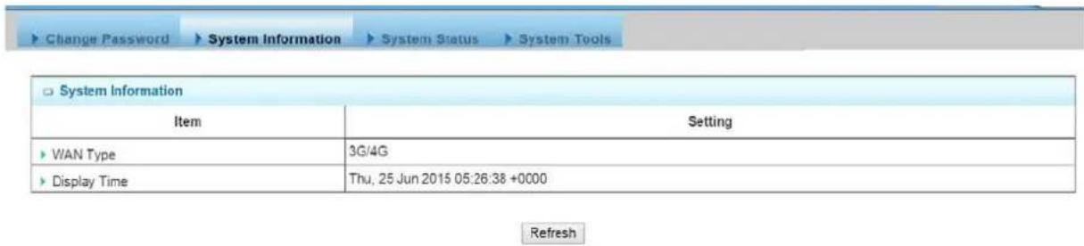
4.4.1.3 System Status
You can view the System Logs in Web UI. You also can send the logs to specific email accounts periodically or instantly by clicking on the "Email Now" command button


Save Refresh
- Web Log: You can select the log types to be collected in the web log area. There are "System", "Attacks", "Drop", and "Debug" types of system logs for you to select.
- View: You can browse, refresh, download, and clear the log messages after clicking on the "View" command button.
- Email Alert: This device can also export system logs via sending emails to specific recipients. The items you have to setup include:
* Enable: Check it if you want to enable Email alert(send system logs via email).
* Server Port: Input the SMTP server IP and port, which are connected with':'. If you do not specify port number, the default value is 25.
* E-mail Addresses: The recipients are the ones who will receive these logs. You can assign more than 1 recipient by using ';' or ',' to separate these email addresses.
* E-mail Subject: The subject of email alert is optional.
- Email Now: A command button to let you email out current web logs right now instead of the email alert period.
4.4.1.4 System Tools
The device supports many system tools, including system time configuration, FW upgrading, system rebooting, system resetting to default, waking on LAN and configuration settings backup.

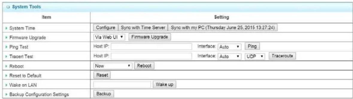
Save
- System Time: There are three approaches to setup the system time. Before the process, some basic information must be filled by clicking on the "Configure" command button. Basic information includes following items:
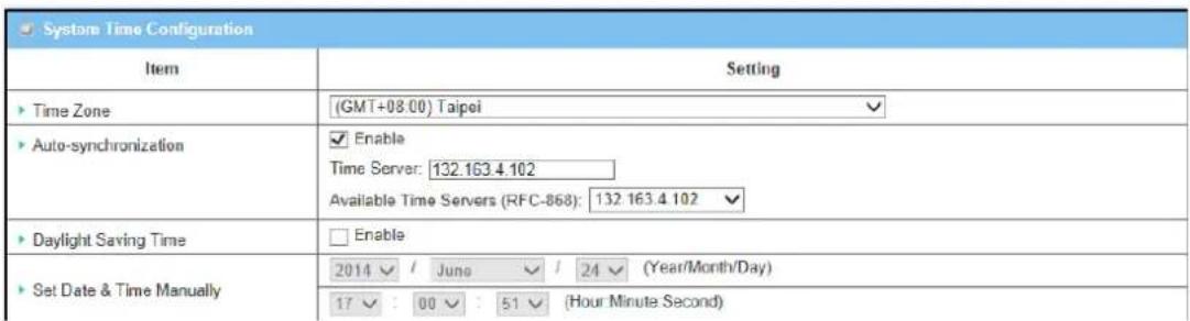
a. Time Zone: Select a time zone where this device locates.
b. Auto-Synchronization: Check the "Enable" check box to enable this function. Besides, you can select a NTP time server to consult UTC time from the available list and by default, it is 132.163.4.102.
c. Daylight Saving Time: Check the "Enable" checkbox to enable this function.
d. Set Date & Time Manually: Set the date and time for system by manual. But Auto-Synchronization must be unchecked beforehand to do it.
Above is the first way to setup system date and time. That is, It is the manual way. The second way is "Sync with Timer Server". Based on your selection of time server in basic information configuration, system will communicate with time server by NTP Protocol to get system date and time after you click on the button. The last way is "Sync with my PC". Click on the button to let system synchronizes its date and time to the ones of the configuration PC.
- FW Upgrade: If new firmware is available, you can upgrade router firmware through the WEB GUI here. After clicking on the "FW Upgrade" command button, you need to specify the file name of new firmware by using "Browse" button, and then click "Upgrade" button to start the FW upgrading process on this device. If you want to upgrade a firmware which is from GPL policy, please check "Accept unofficial firmware".
![Change Password > System Information > System Status > System Tools Firmware Upgrade [ Help ] Firmware Filename 選擇檔案 未選擇任何檔案 Current firmware version is 0LSD0.1001_06171730 Note! Do not interrupt the process or power off the unit when it is being upgraded. When the process is done successfully, the unit will be restarted automatically. □ Accept unofficial firmware. Upgrade Cancel](/content/2026/05/914011/images/168a2dec9c3badc580a347fe7cec16e816a10220c1bc5703270be579772af810.jpg)
NOTE.PLEASE DO NOT TURN THE DEVICE OFF WHEN UPGRADE IS PROCEEDING.
- Ping Test: This allows you to specify an IP/FQDN and the test interface, so system will try to ping the specified device to test whether it is alive after clicking on the "Ping" button. A test result window will appear beneath it. There is a "Close" command button there can let the test result windows disappear.

- Traceroute Test: Trace route command is a network diagnostic tool for displaying the route(path) and measuring transit delays of packets across an IP network. Traceroute proceeds unless all(three) sent packets are lost more than twice, then the connection is lost and the route cannot be evaluated. Ping, on the other hand, only computes the final round-trip times from the destination point. First, you need to specify an IP/FQDN, the test interface and used protocol number. Used protocol number is either "UDP" or "ICMP", and by default, it is "UDP". Then, system will try to trace the specified device to test whether it is alive after clicking on the "Traceroute" button. A test result window will appear beneath it. There is a "Close" command button there can let the test result windows disappear.

-
Reboot: You can also reboot this device by clicking the "Reboot" button.
-
Reset to Default: You can also reset this device to factory default settings by clicking the "Reset" button.
-
Wake on LAN: Wake on LAN(WOL) is an Ethernet networking standard that allows a computer to be turned on or awakened by a network message. You can specify the MAC address of the computer, in your LAN network, to be remotely turned on by clicking on the "Wake up" command button.
-
Backup Configuration Settings: You can backup your settings by clicking the "Backup" button and save it as a bin file. Once you want to restore these settings, please click Firmware Upgrade button and use the bin file you saved.
Afterwards, click on "Save" to store your settings or click "Undo" to give up the changes.
4.4.2 Scheduling
You can set the schedule time to decide which service will be turned on or off. The added rules will be listed as below and they can be up to 100 rules.

-
Enable: Enable or disable the scheduling function.
-
Add New Rule: To create a schedule rule, click the "Add New" button or the "Add New Rule" button at the bottom. When the next dialog popped out you can edit the Name of Rule, Policy, and set the schedule time (Week day, Start Time, and End Time). In a schedule rule, it collects 8 time periods to organize it. You also can specify the rule is to define the enable timing ("In active except the selected days and hours below") or disable timing ("Active except the selected days and hours below").
| Time Schedule Configuration | |
| Item | Setting |
| Rule Name | Sleeping Time |
| Rule Policy | Activate the Selected Days and Hours Below |
| Time Period Definition | |||
| ID | Week Day | Start Time (hh:mm) | End Time (hh:mm) |
| 1 | Every Day | 01:00 | 08:00 |
| 2 | -- choose one -- | □ | □ |
| 3 | -- choose one -- | □ | □ |
| 4 | -- choose one -- | □ | □ |
| 5 | -- choose one -- | □ | □ |
| 6 | -- choose one -- | □ | □ |
| 7 | -- choose one -- | □ | □ |
| 8 | -- choose one -- | □ | □ |
Afterwards, click "save" to store your settings or click "Undo" to give up the changes.
4.4.3 Grouping
This device supports three types of objects to be grouped. They are host objects, file extension objects and L7 Application objects. One “Enable” checkbox provides user to activate the grouping function for all types of objects.

4.4.3.1 Grouping Configuration

- Grouping: Check the "Enable" box to activate the grouping function.
4.4.3.2 Host Grouping
4.4.3.2.1 Host Group List
Host Group List can show the list of all host groups and their member lists and bound services in this window. You can add one new grouping rule by clicking on the "Add" command button. But also you can modify some existed host groups by clicking corresponding "Edit" command buttons at the end of each group record in the Host Group List. Besides, unnecessary groups can be removed by checking the "Select" box for those groups and then clicking on the "Delete" command button at the Host Group List caption.

-
Add: Click on the button to add one host group.
-
Delete: Click on the button to delete the host groups that are specified in advance by checking on the "Select" box of those groups.
-
Edit: Click on the button to edit the host group.
-
Select: Select the host group to delete.
4.4.3.2.2 Host Group Configuration

-
Group Name: Define the name of group.
-
Member List: Show the list of members that have joined the group. A delete button 'is behind each member and can be used to remove the member from the group.
-
Multiple Bound Services: The defined group object can be used in various applications, like Firewall or QoS & BWM.
-
Member to Join: To define a member by using IP address or MAC address. Choose "IP Address-based" or "MAC Address-based" first and then type specific value for the member. Click on the "Join" button to join the member in the group.
-
Group: Check the "Enable" box to activate the group definition.
4.4.3.3 File Extension Grouping
4.4.3.3.1 File Extension Group List
File Extension Group List can show the list of all file extension groups and their member lists and bound services in this window. You can add one new grouping rule by clicking on the "Add" command button. But also you can modify some existed file extension groups by clicking corresponding "Edit" command buttons at the end of each group record in the File Extension Group List. Besides, unnecessary groups can be removed by checking the "Select" box for those groups and then clicking on the "Delete" command button at the File Extension Group List caption.
| File Extension Group List Add Delete | |||||
| ID | Group Name | File Extension Group List | Bound Services | Enable | Actions |
-
Add: Click on the button to add one file extension group.
-
Delete: Click on the button to delete the file extension groups that are specified in advance by checking on the "Select" box of those groups.
-
Edit: Click on the button to edit the file extension group.
-
Select: Select the file extension group to delete.
4.4.3.3.2 File Extension Group Configuration
| File Extension Group Configuration | |
| Item | Setting |
| Group Name | Execution #1 |
| File Extension Group List | .com ☑ .exe ☑ |
| Multiple Bound Services | Firewall Qos |
| Member to Join | Execution √ .exe √ Join |
| Group | Enable |
-
Group Name: Define the name of group.
-
Member List: Show the list of members that have joined the group. A delete button is behind each member and can be used to remove the member from the group.
-
Multiple Bound Services: The defined group object can be used in various applications, like Firewall or QoS & BWM.
-
Member to Join: To define a member by selecting a file extension type category and a file extension name. File extension categories include "Image", "Video", "Audio", "Java", "Compression" and "Execution". And each category has its own list of file extension objects, like ".exe". Choose one to join the group by clicking on the "Join" button.
-
Group: Check the "Enable" box to activate the group definition.
4.4.3.4 L7 Application Grouping
4.4.3.4.1 L7 Application Group List
L7 Application Group List can show the list of all file extension groups and their member lists and bound services in this window. You can add one new grouping rule by clicking on the "Add" command button. But also you can modify some existed file extension groups by clicking corresponding "Edit" command buttons at the end of each group record in the File Extension Group List. Besides, unnecessary groups can be removed by checking the "Select" box for those groups and then clicking on the "Delete" command button at the File Extension Group List caption.

-
Add: Click on the button to add one L7 application group.
-
Delete: Click on the button to delete the L7 application groups that are specified in advance by checking on the "Select" box of those groups.
-
Edit: Click on the button to edit the L7 application group.
-
Select: Select the file extension group to delete.
4.4.3.4.2 L7 Application Group Configuration

-
Group Name: Define the name of group.
-
Member List: Show the list of members that have joined the group. A delete button is behind each member and can be used to remove the member from the group.
-
Multiple Bound Services: The defined group object can be used in various applications, like Firewall or QoS & BWM.
-
Member to Join: To define a member by selecting a L7 application category and an application name. L7 application categories include "Chat", "P2P", "Proxy" and "Streaming". And each category has its own list of L7 application objects, like "eMule". Choose one to join the group by clicking on the "Join" button.
-
Group: Check the "Enable" box to activate the group definition.
4.4.4 External Servers
This device supports six types of external server objects to be created. They are Email Server objects, Syslog Server objects, RADIUS Server objects, Active Directory Server objects, LDAP Server objects and UAM Server objects. These objects can be used in other applications of system, like system log emailing to email server or sending to syslog server in [System] - [System Related] - [System Status], captive portable function in [Applications] - [Captive Portable], SMS forwarding to email server or syslog server in [Applications] - [Mobile Applications] - [SMS], AP Management alerting system in [Applications] - [AP Management], and IO Management alerting handler in [Applications] - [IO Management]. Above usage examples depend on the provided functions of different product models.

| External Server ListAddDelete | ||||||
| ID | Server Name | Server IP/FQDN | Server Port | Server Type | Enable | Setting |
| 1 | hotspot | hotspotsystem.com | 80 | UAM Server | Edit Select | |
| 2 | radius | radius.hotspotsystem.com | 1812 | RADIUS Server | Edit Select | |

4.4.4.1 External Server List
External Server List can show the list of all defined external server objects and their attributes in this window. You can add one new external server object by clicking on the "Add" command button. But also you can modify some existed external server objects by clicking corresponding "Edit" command buttons at the end of each object record in the External Server List. Besides, unnecessary objects can be removed by checking the "Select" box for those objects and then clicking on the "Delete" command button at the External Server List caption.
| External Server List Add Delete | ||||||
| ID | Server Name | Server IP/FQDN | Server Port | Server Type | Enable | Setting |
| 1 | JPEmailAccount | email.amit.com.tw | 25 | undefined | ☑ | Edit ☑ Select |
| 2 | JPEmailAccount | email.amit.com.tw | Email Server | ☑ | Edit ☐ Select | |
-
Add: Click on the button to add one external server object.
-
Delete: Click on the button to delete the external server objects that are specified in advance by checking on the "Select" box of those objects.
-
Edit: Click on the button to edit the external server object.
-
Select: Select the external server object to delete.
4.4.4.2 External Server Configuration

- Server Name: Define the name of external server object.
- Server IP/FQDN: Specify the IP address or domain name of external server.
-
Server Port: Specify the service port of external server.
-
Server Type: Select one server type from the option list of "Email Server", "Syslog Server", "RADIUS Server", "Active Directory Server", "LDAP Server" and "UAM Server". Based on your selection, there are several parameters need to specify. When you select "Email Server" option for the Server Type, you must specify two more parameters, "User Name" and "Password". When "Syslog Server", no more parameter is required. When "RADIUS Server", you can specify primary RADIUS server and secondary RADIUS server for redundancy. For each server, following parameters need to be specified: Shared Key, Authentication Protocol (CHAP or PAP), Session Timeout (1\~60Mins) and Idle Timeout(1\~15Mins). When "Active Directory" Server, you must specify one more parameter, "Domain". When "LDAP" Server, one more parameter, Base Domain Name. When "NT Domains" Server, one more parameter: "Work group". When "UAM" Server, following parameters must be provided: "Login URL", "Shared Secret", "NAS/Gateway ID", "Location ID" and "Location Name". Among them, Location Name is optional.
-
Server: Check the "Enable" box to activate the external server object.
4.4.5 MMI
4.4.5.1 MMI

You can set UI administration time-out duration in this page. If the value is "0", means the time-out is unlimited.
5
VH-4GW Specifications
The specification of VH-4GW is subject to change without notice. Please use the information with caution.
5.1 Features
- Cellular Gateway for Vehicle LTE-Fi Hotspot applications.
- 1x embedded LTE module
● 1x10/100 WAN - 1x10/100 LAN
● 4G/3G and WAN Load Balance
● 802.11n 2T2R with 3 dBi detachable Antenna
● Fully protocol stack for both IPv4 and IPv6, - VPN supported
● QoS and Bandwidth management
● SNMP, Web, and TR069. SMS for administrator to manage system
● Power input range from 9V \~ 36Vdc for vehicle battery
5.2 Specifications
| Chipset | MDM9215 (3G/4G) |
| WAN | LTE Band:1/3/7/8/20/40 |
| 3G Band : 900/2100Mhz | |
| 10/100M WAN Port x 1 | |
| LAN Port | 10/100M (Auto-MDI/MDI-X) UTP Port x 1 |
| Antenna | 2 x 3 dBi detachable Onmi Antenna for LTE |
| 2 x 5 dBi detachable Onmi Antenna for WiFi | |
| Detachable GPS antenna | |
| Frequency Range for WiFi | 2.4G: 2.4000~2.4835GHz |
| WiFi Operation Mode | AP Router, WDS, WDS Hybrid Modes |
| Wireless Security | WEP |
| WPA-PSK | |
| WPA2-PSK | |
| WPA-Radius | |
| 802.1x/EAP | |
| Software | One SIM Card slot |
| IPv6: 6-in-4, 6-to-4 | |
| Multi-SSID | |
| WPS | |
| WMM | |
| VLAN | |
| NAT: ALG, Special AP,DMZ Host, Virtual Server, | |
| PPTP/L2TP/IPSec Passthrough | |
| DDNS | |
| Pacaket Filters | |
| URL Blocking | |
| Web Content Filter | |
| MAC Address Control | |
| Application Filter | |
| QoS and Band Width Management | |
| VPN Tunneling: IPSec, PPTP, L2TP,GRE VPN, L2TP Over IPSec | |
| VPN Scenario: Site to Site, Site to Host, Host to Site, Host to Host, Dynamic VPN | |
| Redundancy: VRRP | |
| Captive Portal | |
| Status & Statistics | |
| Scheduling | |
| FW upgrade | |
| Backup & Restore Setting | |
| Management | Web |
| Telnet | |
| SNMP | |
| SMS | |
| TR-069 | |
| WiFi Output Power (EIRP) | ETSI: 2.4GHz: 19±1dBm |
| Receive Sensitivity | 2.4GHz: -90±2dBm |
| Power Supply | 9~36Vdc |
| Temperature | Operating: -20 ~ 60°C |
| Storage: -40 ~ 85°C | |
| Humidity | Operating: 10~90% (Non-Condensing) |
| Storage: max. 95% (Non-Condensing) | |
| Certification | CE |
| Dimension | 150 x 107 x 31 (mm) |
| Product Weight | 380 (g) |
6
Wireless Network Glossary
The wireless network glossary contains explanation or information about common terms used in wireless networking products. Some of information in this glossary might be outdated, please use with caution.
802.11a
An IEEE specification for wireless networking that operates in the 5 GHz frequency range (5.425 GHz to 5.750 GHz) with a maximum of 54 Mbps data transfer rate. The 5 GHz frequency band is not as crowded as the 2.4 GHz band. In addition, the 802.11a have 12 non-overlapping channels, comparing to 802.11b/g's 3 non-overlapping channels. This means the possibility to build larger non-interfering networks. However, the 802.11a deliver shorter distance at the same output power when comparing to 802.11g.
802.3ad
802.3ad is an IEEE standard for bonding or aggregating multiple Ethernet ports into one virtual port (also known as trunking) to increase the bandwidth.
802.3af
This is the PoE (Power over Ethernet) standard by IEEE committee.803.af uses 48V POE standard that can deliver up to 100 meter distance over Ethernet cable.
802.11b
International standard for wireless networking that operates in the 2.4 GHz frequency band (2.4 GHz to 2.4835 GHz) and provides a throughput up to 11 Mbps.
802.1d STP
Spanning Tree Protocol. It is an algorithm to prevent network from forming. The STP protocol allows network to provide a redundant link in the event of a link failure. It is advice to turn on this option for multi-link bridge network.
802.11d
Also known as “Global Roaming”.802.11d is a standard for use in countries where systems using other standards in the 802.11 family are not allowed to operate.
802.11e
The IEEE QoS standard for prioritizing traffic of the VoIP and multimedia applications. The WMM is based on a subset of the 802.11e.
802.11g
A standard provides a throughput up to 54 Mbps using OFDM technology. It also operates in the 2.4 GHz frequency band as 802.11b.802.11g devices are backward compatible with 802.11b devices.
802.11h
This IEEE standard defines the TPC (transmission power control) and DFS(dynamic frequency selection) required to operate WiFi devices in 5GHz for EU.
802.11i
The IEEE standard for wireless security.802.11i standard includes TKIP, CCMP, and AES encryption to improve wireless security .It is also known as WPA2.
802.11n
The IEEE 802.11 standard improves network throughput over 802.11a and 802.11g, with a significant increase in the maximum data rate from 54 Mbps to 600 Mbps.802.11n standardized support for multiple-input multiple-output (MIMO) and frame aggregation, and security improvements.
802.1Q Tag VLAN
In 802.1Q VLAN, the VLAN information is written into the Ethernet packet itself. Each packet carries a VLAN ID(called Tag) as it traveled across the network. Therefore, the VLAN configuration can be configured across multiple switches. In 802.1Q spec, possible 4096 VLAN ID can be created. Although for some devices, they can only view in frames of 256 ID at a time.
802.1x
802.1x is a security standard for wired and wireless LANs. In the 802.1x parlance, there are usually supplicants (client), authenticator (switch or AP), and authentication server (radius server) in the network. When a supplicants request a service, the authenticator will pass the request and wait for the authentication server to grant access and register accounting. The 802.1x is the most widely used method of authentication by WISP.
Adhoc
A Peer-to-Peer wireless network. An Adhoc wireless network do not use wireless AP or router as the central hub of the network. Instead, wireless client are connected directly to each other. The disadvantage of Adhoc network is the lack of wired interface to Internet connections. It is not recommended for network more than 2 nodes.
Access Point (AP)
The central hub of a wireless LAN network. Access Points have one or more Ethernet ports that can connect devices (such as Internet connection) for sharing. Multi-function Access Point can also function as an Ethernet client, wireless bridge, or repeat signals from other AP. Access Points typically have more wireless functions comparing to wireless routers.
ACK Timeout
Acknowledgement Timeout Windows. When a packet is sent out from one wireless station to the other, it will waits for an Acknowledgement frame from the remote station. The station will only wait for a certain amount of time, this time is called the ACK timeout. If the ACK is NOT received within that timeout period then the packet will be re-transmitted resulting in reduced throughput. If the ACK setting is too high then throughput will be lost due to waiting for the Ack Window to timeout on lost packets. If the ACK setting is too low then the ACK window will have expired and the returning packet will be dropped, greatly lowering throughput. By having the ability to adjust the ACK setting we can effectively optimize the throughput over long distance links. This is especially true for 802.11a and 802.11g networks. Setting the correct ACK timeout value need to consider 3 factors: distance, AP response time, and interference. The VH-4GW provide ACK adjustment capability in form of either distance or direct input. When you enter the distance parameter, the VH-4GW will automatically calculate the correct ACK timeout value.
Bandwidth Management
Bandwidth Management controls the transmission speed of a port, user, IP address, and application. Router can use bandwidth control to limit the Internet connection speed of individual IP or Application. It can also guarantee the speed of certain special application or privileged IP address - a crucial feature of QoS (Quality of Service) function. The VH-4GW's features both "Per-user Bandwidth Control" and "Total Bandwidth Control". "Per-user Bandwidth Control" allow administrator to define the maximum bandwidth of each user by IP, IP Group, or MAC address. Total Bandwidth define the maximum bandwidth of wireless or Ethernet interface.
Bootloader
Bootloader is the under layering program that will start at the power-up before the device loads firmware. It is similar to BIOS on a personal computer. When a firmware crashed, you might be able to recover your device from bootloader.
Bridge
A product that connects 2 different networks that uses the same protocol. Wireless bridges are commonly used to link network across remote buildings. For wireless application, there are 2 types of Bridges. WDS Bridge can be used in Point-to-Point or Point-to-Multipoint topology. Bridge Infrastructure works with AP mode to form a star topology.
Cable and Connector Loss: During wireless design and deployment, it is important to factor in the cable and connector loss. Cable and connector loss will reduce the output power and receiver sensitivity of the radio at connector end. The longer the cable length is, the more the cable loss. Cable loss should be subtracted from the total output power during distance calculation. For example, if the cable and connector loss is 3dBm and the output power is 20dBm; the output power at the cable end is only 17dBm.
Client
Client means a network device or utility that receives service from host or server. A client device means end user device such as wireless cards or wireless CPE.
CPE Devices
CPE stands for Customer Premises Equipment. A CPE is a device installed on the end user's side to receive network services. For example, on an ADSL network, the ADSL modem/router on the subscriber's home is the CPE device. Wireless CPE means a complete Wireless (usually an AP with built-in Antenna) that receive wireless broadband access from the WISP. The opposite of CPE is CO.
CTS
Clear To Send. A signal sent by a device to indicate that it is ready to receive data.
DDNS
Dynamic Domain Name System. An algorithm that allows the use of dynamic IP address for hosting Internet Server. A DDNS service provides each user account with a domain name. A router with DDNS capability has a built-in DDNS client that updates the IP address information to DDNS service provider whenever there is a change. Therefore, users can build website or other Internet servers even if they don't have fixed IP connection.
DHCP
Dynamic Hosting Configuration Protocol. A protocol that enables a server to dynamically assign IP addresses. When DHCP is used, whenever a computer logs onto the network, it automatically gets an IP address assigned to it by DHCP server. A DHCP server can either be a designated PC on the network or another network device, such as a router.
DMZ
Demilitarized Zone. When a router opens a DMZ port to an internal network device, it opens all the TCP/UDP service ports to this particular device. The feature is used commonly for setting up H.323 VoIP or Multi-Media servers.
DNS
A program that translates URLs to IP addresses by accessing a database maintained on a collection of Internet servers.
Domain Name
The unique name that identifies an Internet site. Domain Names always have 2 or more parts, separated by dots. In www.airlive.com, the "airlive.com" is the domain name.
DoS Attack
Denial of Service. A type of network attack that floods the network with useless traffic. Many DoS attacks, such as the Ping of Death and Teardrop attacks, exploit limitations in the TCP/IP protocols.
Encryption
Encoding data to prevent it from being read by unauthorized people. The common wireless encryption schemes are WEP, WPA, and WPA2.
ESSID (SSID)
The identification name of an 802.11 wireless network. Since wireless network has no physical boundary liked wired Ethernet network, wireless LAN needs an identifier to distinguish one network from the other. Wireless clients must know the SSID in order to associate with a WLAN network. Hide SSID feature disable SSID broadcast, so users must know the correct SSID in order to join a wireless network.
Firewall
A system that secures a network and prevents access by unauthorized users. Firewalls can be software, router, or gateway. Firewalls can prevent unrestricted access into a network, as well as restricting data from flowing out of a network.
Firmware
The program that runs inside embedded device such as router or AP. Many network devices are firmware upgradeable through web interface or utility program.
FTP
File Transfer Protocol. A standard protocol for sending files between computers over a TCP/IP network and the Internet.
Fragment Threshold
Frame Size larger than this will be divided into smaller fragment. If there are interferences in your area, lower this value can improve the performance. If there are not, keep this parameter at higher value. The default size is 2346. You can try 1500, 1000, or 500 when there are interference around your network.
Full Duplex
The ability of a networking device to receive and transmit data simultaneously. In wireless environment, this is usually done with 2 or more radios doing load balancing.
Gateway
In the global Internet network, the gateways are core routers that connect networks in different IP subnet together. In a LAN environment with an IP sharing router, the gateway is the router. In an office environment, gateway typically is a multi-function device that integrates NAT, firewall, bandwidth management, and other security functions.
Hotspot
A place where you can access Wi-Fi service. The term hotspot has two meanings in wireless deployment. One is the wireless infrastructure deployment; the other is the Internet access billing system. In a hotspot system, a service provider typically need an authentication and account system for billing purposes, and a wireless AP network to provide access for customers.
IGMP Snooping
Internet Group Management Protocol (IGMP) is a Layer 3 protocol to report IP multicast memberships to neighboring multicast switches and routers. IGMP snooping is a feature that allows an Ethernet switch to "listen in" on the IGMP conversation between hosts and routers. A switch support IGMP snooping has the possibility to avoid multicast traffic being treated as broadcast traffic; therefore, reducing the overall traffic on the network.
Infrastructure Mode
A wireless network that is built around one or more access points to provide wireless clients access to wired LAN / Internet service. The opposite of Infrastructure mode is Adhoc mode.
IP address
IP (Internet Protocol) is a layer-3 network protocol that is the basis of all Internet communication. An IP address is 32-bit number that identifies each sender or receiver of information that is sent across the Internet. An IP address has two parts: an identifier of a particular network on the Internet and an identifier of the particular device (which can be a server or a workstation) within that network. The new IPv6 specification supports 128-bit IP address format.
IPsec
IP Security. A set of protocols developed by the IETF to support secure exchange of packets at the IP layer. IPsec has been deployed widely to implement Virtual Private Networks (VPNs).IPsec supports two encryption modes: Transport and Tunnel. Transport mode encrypts only the data of each packet, but leaves the header untouched. The more secure Tunnel mode encrypts both the header and the payload. On the receiving side, an IPSec-compliant device decrypts each packet.
LACP (802.3ad) Trunking
The 802.3ad Link Aggregation standard defines how to combine the several Ethernet ports into one high-bandwidth port to increase the transmission speed. It is also known as port trunking. Both device must set the trunking feature to work.
MAC
Media Access Control. MAC address provides layer-2 identification for Networking Devices. Each Ethernet device has its own unique address. The first 6 digits are unique for each manufacturer. When a network device have MAC access control feature, only the devices with the approved MAC address can connect with the network.
Mbps
Megabits Per Second. One million bits per second; a unit of measurement for data transmission
MESH
Mesh is an outdoor wireless technology that uses Spanning Tree Protocol (STP) and Wireless Distribution system to achieve self-forming, self-healing, and self-configuring outdoor network. MESH network are able to take the shortest path to a destination that does not have to be in the line of site.
MIMO
Multi In Multi Out.A Smart Antenna technology designed to increase the coverage and performance of a WLAN network. In a MIMO device, 2 or more antennas are used to increase the receiver sensitivity and to focus available power at intended Rx.
NAT
Network Address Translation. A network algorithm used by Routers to enables several PCs to share single IP address provided by the ISP. The IP that a router gets from the ISP side is called Real IP, the IP assigned to PC under the NAT environment is called Private IP.
Node
A network connection end point, typically a computer.
Packet
A unit of data sent over a network.
Passphrase
Used much like a password, a passphrase simplifies the WEP encryption process by automatically generating the WEP encryption keys for the company products.
POE
Power over Ethernet. A standard to deliver both power and data through one single Ethernet cable (UTP/STP). It allows network device to be installed far away from power source. A POE system typically compose of 2 main component: DC Injector (Base Unit) and Splitter(Terminal Unit). The DC injector combines the power and data, and the splitter separates the data and power back. A PoE Access Point or CPE has the splitter built-in to the device. The IEEE 802.3af is a POE spec that uses 48 volt to deliver power up to 100 meter distance.
Port
This word has 2 different meaning for networking.
- The hardware connection point on a computer or networking device used for plugging in a cable or an adapter.
- The virtual connection point through which a computer uses a specific application on a server.
PPPoE
Point-to- Point Protocol over Ethernet. PPPoE relies on two widely accepted standards: PPP and Ethernet. PPPoE is a specification for connecting the users on an Ethernet to the Internet through a common broadband medium, such as a single DSL line, wireless device or cable modem.
PPTP
Point-to-Point Tunneling Protocol: A VPN protocol developed by PPTP Forum. With PPTP, users can dial in to their corporate network via the Internet. If users require data encryption when using the Windows PPTP client, the remote VPN server must support MPPE (Microsoft Point-To-Point Encryption Protocol) encryption. PPTP is also used by some ISP for user authentication, particularly when pairing with legacy Alcatel / Thomson ADSL modem.
Preamble Type
Preamble are sent with each wireless packet transmit for transmission status. Use the long preamble type for better compatibility. Use the short preamble type for better performance
Rate Control
Ethernet switches' function to control the upstream and downstream speed of an individual port. Rate Control management uses "Flow Control" to limit the speed of a port. Therefore, the Ethernet adapter must also have the flow control enabled. One way to force the adapter's flow control on is to set a port to half-duplex mode.
RADIUS
Remote Authentication Dial-In User Service. An authentication and accounting system used by many Internet Service Providers (ISPs). When you dial in to the ISP, you must enter your username and password. This information is passed to a RADIUS server, which checks that the information is correct, and then authorizes access to the ISP system. Radius typically uses port 1812 and port 1813 for authentication and accounting port. Though not an official standard, the RADIUS specification is maintained by a working group of the IETF.
Receiver Sensitivity
Receiver sensitivity means how sensitive is the radio for receiving signal. In general; the slower the transmission speed, the more sensitive the radio is. The unit for Receiver Sensitivity is in dB; the lower the absolute value is, the higher the signal strength. For example, -50dB is higher than -80dB.
RJ-45
Standard connectors for Twisted Pair copper cable used in Ethernet networks. Although they look similar to standard RJ-11 telephone connectors, RJ-45 connectors can have up to eight wires, whereas telephone connectors have only four.
Router
An IP sharing router is a device that allows multiple PCs to share one single broadband connection using NAT technology. A wireless router is a device that combines the functions of wireless Access Point and the IP sharing router.
RSSI
Receiver Sensitivity Index. RSSI is a value to show the Receiver Sensitivity of the remote wireless device. In general, remote APs with stronger signal will display higher RSSI values. For RSSI value, the smaller the absolute value is, the stronger the signal. For example, "-50db" has stronger signal than "-80dB". For outdoor connection, signal stronger than -60dB is considered as a good connection.
RTS
Request To Send. A packet sent when a computer has data to transmit. The computer will wait for a CTS (Clear To Send) message before sending data.
RTS Threshold
RTS (Request to Send). The RTS/CTS(clear to send) packet will be send before a frame if the packet frame is larger than this value. Lower this value can improve the performance if there are many clients in your network. You can try 1500, 1000 or 500 when there are many clients in your AP's network.
SNMP
Simple Network Management Protocol. A set of protocols for managing complex networks. The SNMP network contains 3 key elements: managed devices, agents, and network-management systems (NMSs). Managed devices are network devices that content SNMP agents. SNMP agents are programs that reside SNMP capable device's firmware to provide SNMP configuration service. The NMS typically is a PC based software such as HP Open view that can view and manage SNMP network device remotely.
SSH
Developed by SSH Communications Security Ltd., Secure Shell is a program to log into another computer over a network, to execute commands in a remote machine, and to move files from one machine to another. It provides strong authentication and secure communications over insecure channels. It is a replacement for rlogin, rsh, rcp, and rdist.
SSL
Secure Sockets Layer. It is a popular encryption scheme used by many online retail and banking sites to protect the financial integrity of transactions. When an SSL session begins, the server sends its public key to the browser. The browser then sends a randomly generated secret key back to the server in order to have a secret key exchange for that session. SSL VPN is also known as Web VPN. The HTTPS and SSH management interface use SSL for data encryption.
Subnet Mask
An address code mask that determines the size of the network. An IP subnet are determined by performing a BIT-wise AND operation between the IP address and the subnet mask. By changing the subnet mask, you can change the scope and size of a network.
Subnetwork or Subnet
Found in larger networks, these smaller networks are used to simplify addressing between numerous computers. Subnets connect to the central network through a router, hub or gateway. Each individual wireless LAN will probably use the same subnet for all the local computers it talks to.
Super A
Super A is an Atheros proprietary turbo mode to increase speed over standard 802.11a mode. It adds Bursting and Compression to increase the speed. If you live in countries that prohibit the channel binding technology (i.e. Europe), you should choose “Super-A without Turbo) if you need more speed than 11a mode
TCP
A layer-4 protocol used along with the IP to send data between computers over the Internet. While IP takes care of handling the actual delivery of the data, TCP takes care of keeping track of the packets that a message is divided into for efficient routing through the Internet.
Turbo A
Turbo A is an Atheros proprietary turbo mode to increase speed over standard 802.11a mode. It uses channel binding technology to increase speed. There are 2 types of Turbo A modes: Dynamic Turbo and Static Turbo. In Dynamic Turbo, the channel binding will be used only if necessary. In Static Turbo, the channel binding is always on. This protocol may be combined with Super-A model to increase the performance even more. The used of channel binding might be prohibited in EU countries.
TX Output Power
Transmit Output Power. The TX output power means the transmission output power of the radio. Normally, the TX output power level limit for 2.4GHz 11g/b is 20dBm at the antenna end. The output power limit for 5GHz 802.11a is 30dBm at the antenna end.
UDP
User Datagram Protocol. A layer-4 network protocol for transmitting data that does not require acknowledgement from the recipient of the data.
Upgrade
To replace existing software or firmware with a newer version.
Upload
To send a file to the Internet or network device.
URL
Uniform Resource Locator. The address of a file located on the Internet.
VPN
Virtual Private Network. A type of technology designed to increase the security of information transferred over the Internet. VPN creates a private encrypted tunnel from the end user's computer, through the local wireless network, through the Internet, all the way to the corporate network.
Walled Garden
On the Internet, a walled garden refers to a browsing environment that controls the information and Web sites the user is able to access. This is a popular method used by ISPs in order to keep the user navigating only specific areas of the Web.
WAN
Wide Area Network. A communication system of connecting PCs and other computing devices across a large local, regional, national or international geographic area. A WAN port on the network device means the port (or wireless connection) that is connected to the Internet side of the network topology.
WEP
Wired Equivalent Privacy. A wireless encryption protocol. WEP is available in 40-bit (64-bit), 108-bit (128-bit) or 152-bit (Atheros proprietary) encryption modes.
Wi-Fi
Wireless Fidelity. An interoperability certification for wireless local area network (LAN) products based on the IEEE 802.11 standards. The governing body for Wi-Fi is called Wi-Fi Alliance (also known as WECA).
WiMAX
Worldwide Interoperability for Microwave Access. A Wireless Metropolitan Network technology that complies with IEEE 802.16 and ETSI Hiperman standards. The original 802.16 standard call for operating frequency of 10 to 66Ghz spectrum. The 802.16a amendment extends the original standard into spectrum between 2 and 11 Ghz.802.16d increase data rates to between 40 and 70 Mbps/s and add support for MIMO antennas, QoS, and multiple polling technologies.802.16e adds mobility features, narrower bandwidth (a max of 5 mhz), slower speed and smaller antennas. Mobility is allowed up to 40 mph.
WDS
Wireless Distribution System. WDS defines how multiple wireless Access Point or Wireless Router can connect together to form one single wireless network without using wired uplinks. WDS associate each other by MAC address, each device
WLAN
Wireless Local Area Network. A type of local-area network that uses high-frequency radio waves rather than wires to communicate between nodes. The most popular standard for WLAN is the 802.11 standards.
WMM
Wi-Fi Multimedia (WMM) is a standard to prioritize traffic for multimedia applications. The WMM prioritize traffic\ on Voice-over-IP (VoIP), audio, video, and streaming media as well as traditional IP data over the AP.
WMS
Wireless Management System. An utility program to manage multiple wireless AP/Bridges.
WPA
Wi-Fi Protected Access. It is an encryption standard proposed by WiFi for advance protection by utilizing a password key (TKIP) or certificate. It is more secure than WEP encryption. The WPA-PSK utilizes pre-share key for encryption/authentication.
WPA2
Wi-Fi Protected Access 2.WPA2 is also known as 802.11i.It improves on the WPA security with CCMP and AES encryption. The WPA2 is backward compatible with WPA.WPA2-PSK utilizes pre-share key for encryption/authentication.
- User Manual
- Air Live®
- Powered by OvisLink Corp.
- Version 1.0
- Copyright & Disclaimer
- Table of Contents
- Introduction...... 1
- Installing the VH-4GW 5
- Configuring the VH-4GW.... 11
- Web Management 27
- Basic Network.... 29
- Advanced Network....87
- Application....141
- System 157
- VH-4GW Specifications ....170
- Wireless Network Glossary....173
- 1
- Introduction
- Overview
- Special Notice
- How to Use This Guide
- Recommended Reading
- Firmware Upgrade and Tech Support
- Features
- Wireless Operation Modes
- WDS Bridge Mode
- AP Router Mode
- 2
- Installing the VH-4GW
- Before You Start
- Package Content
- Knowing your VH-4GW
- Hardware Installation
- Insert the SIM card
- Step 1:
- Step 2:
- Step 3:
- Connecting Power
- Mount VH-4GW
- Restore Settings to Default
- 3
- Configuring the VH-4GW
- Important Information
- Prepare Your PC
- Easy Setup by Web Interface
- Wizard
- Configure with the Network Setup Wizard
- Step 1 : Guideline
- Step 2: Change Password
- Step 3: Time Zone
- Step 4 WAN Interface setting
- Step 4-1 : When 3G/4G is selected
- Step 4-2 : When Ethernet is selected
- Step 5: Ethernet LAN interface
- Step 6 WiFi LAN (2.4G)
- Step 7 Confirm and Apply
- Step 8 Counting Down
- Configure with the VPN setup wizard
- Step 3-3: L2TP
- Step 3-4: GRE
- Step 4: Confirm and Apply
- Status
- Dashboard
- Networks Status
- Connection Diagram
- WAN Interface IPv4 Network Status
- WAN Interface IPv6 Network Status
- LAN Interface Status
- 3G/4G Modem Status
- Internet Traffic Statistics
- Device Time
- WiFi Status
- WiFi Virtual AP List
- WiFi Traffic Statistics
- LAN Client List
- Firewall Status
- Packet Filters
- URL Blocking
- Web Content Filters
- MAC Control
- Application Filters
- IPS
- Options
- VPN Status
- IPSec Status
- PPTP Server Status
- PPTP Client Status
- L2TP Server Status
- L2TP Client Status
- System Management Status
- SNMP Linking Status
- SNMP Trap Information
- TR-069 Status
- DDNS Status
- UPNP Port Status
- Statistic & Reports
- GNSS
- 4
- Web Management
- Basic Network
- WAN Setup
- Physical Interface
- Internet Setup
- 3G/4G WAN - 3G/4G
- Dynamic IP Address
- Static IP address
- PPP over Ethernet
- PPTP
- L2TP
- By Smart Weight
- By Priority
- By User Policy
- LAN and VLAN Setup
- Ethernet LAN
- VLAN
- VLAN Scenarios
- - Port-Based VLAN Tagging for DiffServ
- - Tag-based VLAN Tagging for Location-free Departments
- • VLAN Group Access Control
- VLAN Group Internet Access
- Inter VLAN Group Routing:
- Port-Based VLAN
- Tag-Based VLAN
- WiFi Setup
- WiFi Configuration
- AP Router Mode
- - Open
- - Shared
- - Auto
- - WPA-PSK
- - WPA
- - WPA2-PSK
- - WPA2
- - WPA-PSK/WPA2-PSK
- - WPA/WPA2
- WPS Setup
- Registrar Mode
- Enrollee Mode
- Wireless Client List
- Advance Configuration
- IPv6 Setup
- 6 to 4
- to 4 WAN Type Configuration
- LAN Configuration
- Address Auto-configuration
- 6 in 4
- in 4 WAN Type Configuration
- NAT/Bridging
- Configuration
- Virtual Server & Virtual Computer
- Virtual Server
- Virtual Computer
- Special AP & ALG
- DMZ
- Routing Setup
- Status Routing
- Dynamic Routing
- RIP
- OSPF
- BGP
- Routing Information
- Client/Server/Proxy
- Dynamic DNS
- DHCP Server
- DHCP Server Configuration
- Fixed Mapping
- Advanced Network
- Firewall
- Configuration
- Packet Filters
- Configuration
- Packet Filter List
- Packet Filter Rule Configuration
- URL Blocking
- Configuration
- URL Blocking Rule List
- URL Blocking Rule Configuration
- Web Content Filters
- Configuration
- Web Content Filter Rule List
- Web Content Rule Configuration
- MAC Control
- Configuration
- MAC Control Rule List
- MAC Control Rule Configuration
- Application Filters
- Configuration
- IPS
- Options
- QoS & BWM
- Configuration
- Rule-base QoS
- Flexible QoS Rule Definition
- Configuration
- QoS Rule List
- QoS Rule Configuration
- Example#1 for adding a "DSCP" type QoS rule
- Example#2 for adding a "Connection Sessions" type QoS rule
- VPN Setup
- Configuration
- IPSec
- IPSec VPN Tunnel Scenarios
- - Site to Site
- - Dynamic VPN
- - Site to Site – Support Full Tunnel Application
- IPSes Configuration
- Tunnel List and Status
- Tunnel Configuration
- Local & Remote Configuration
- Authentication
- IKE Phase
- Negotiation Mode: Choose Main Mode or Aggressive Mode:
- X-Auth: For the extended authentication function (XAUTH), the VPN client(or initiator) needs to provide additional user information to the remote VPN server
- Dead Peer Detection: This feature will detect if remote VPN peer still exists. Delay indicates the interval between detections, and Time out indicates the timeout of detected to be dead.
- Phase 1 Key Life Time: The value of life time represents the life time of the key which is dedicated at Phase 1 between both end gateways.
- IKE Proposal Definition
- IPSec Phase
- IPSec Proposal Definition
- Manual Proposal
- PPTP
- PPTP / L2TP VPN Tunnel Scenarios
- PPTP Server Configuration
- PPTP Server Status
- User Account List
- User Account Configuration
- PPTP Client
- PPTP Client List & Status
- PPTP Client Configuration
- L2TP
- L2TP Server Configuration
- L2TP Server Status
- User Account List
- User Account Configuration
- L2TP Client
- L2TP Client List & Status
- L2TP Client Configuration
- GRE
- GRE VPN Tunnel Scenario
- GRE Configuration
- GRE Tunnel Definition
- GRE rule Configuration
- Redundancy
- VRRP
- System Management
- TR--069
- SNMP
- Telnet CLI
- UPnP
- Certificate
- My Certificate
- Root CA
- Local Certificate List
- Trusted Certificate
- Trusted CA Certification List
- Trusted Client Certification List
- Issue Certificates
- Application
- Mobile Application
- SMS
- SMS Summary
- Create New SMS Message
- Read New SMS Message
- USSD
- USSD Configuration
- USSD Profile List
- USSD Profile Configuration
- Comments: Add comments for this profile.
- Send USSD Command
- Remote Management
- Management Settings
- Command Settings
- Notification Settings
- Access Control List
- Captive Portal
- External Captive Portal
- Position Applications
- GNSS
- Configuration
- • GNSS
- - GNSS Type
- - GPS Message Type
- • SBAS
- - Assisted GPS
- - Data to Storage
- Remote Host List
- - Host Name
- - Host IP
- - Protocol Type
- - Port Number
- - Interval
- - Prefix Message
- - Suffix Message
- Scenario of location tracking for fleet management
- System
- System Related
- Change Password
- System Information
- System Status
- System Tools
- Scheduling
- Grouping
- Grouping Configuration
- Host Grouping
- Host Group List
- Host Group Configuration
- File Extension Grouping
- File Extension Group List
- File Extension Group Configuration
- L7 Application Grouping
- L7 Application Group List
- L7 Application Group Configuration
- External Servers
- External Server List
- External Server Configuration
- MMI
- MMI
- 5
- VH-4GW Specifications
- Features
- Specifications
- 6
- Wireless Network Glossary
- 802.11a
- 802.3ad
- 802.3af
- 802.11b
- 802.1d STP
- 802.11d
- 802.11e
- 802.11g
- 802.11h
- 802.11i
- 802.11n
- 802.1Q Tag VLAN
- 802.1x
- Adhoc
- Access Point (AP)
- ACK Timeout
- Bandwidth Management
- Bootloader
- Bridge
- Client
- CPE Devices
- CTS
- DDNS
- DHCP
- DMZ
- DNS
- Domain Name
- DoS Attack
- Encryption
- ESSID (SSID)
- Firewall
- Firmware
- FTP
- Fragment Threshold
- Full Duplex
- Gateway
- Hotspot
- IGMP Snooping
- Infrastructure Mode
- IP address
- IPsec
- LACP (802.3ad) Trunking
- MAC
- Mbps
- MESH
- MIMO
- NAT
- Node
- Packet
- Passphrase
- POE
- Port
- PPPoE
- PPTP
- Preamble Type
- Rate Control
- RADIUS
- Receiver Sensitivity
- RJ-45
- Router
- RSSI
- RTS
- RTS Threshold
- SNMP
- SSH
- SSL
- Subnet Mask
- Subnetwork or Subnet
- Super A
- TCP
- Turbo A
- TX Output Power
- UDP
- Upgrade
- Upload
- URL
- VPN
- Walled Garden
- WAN
- WEP
- Wi-Fi
- WiMAX
- WDS
- WLAN
- WMM
- WMS
- WPA
- WPA2
Brand : AIRLIVE
Model : VH-4GW
Category : Wi-Fi Router