
SMB/E01 - Radio transmitter Lectrosonics - Free user manual and instructions
Find the device manual for free SMB/E01 Lectrosonics in PDF.


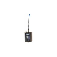
| Product Type | Wireless Bodypack Transmitter |
| Model | SMB/E01 (Single Battery) |
| Dimensions (without microphone) | 2.3 x 1.8 x 0.64 in (58 x 46 x 16 mm) |
| Weight (with lithium battery) | 2.7 oz (75.9 g) |
| Power Source | 1.5V AA lithium or rechargeable NiMH battery |
| Battery Life | Alkaline: 2 hours; Lithium: 7.25 hours; NiMH (2500mAh): 5 hours |
| Frequency Range | 470.100–861.900 MHz depending on block (256 frequencies, 100 kHz steps) |
| RF Power Output | 50 mW nominal |
| Modulation | FM |
| Audio Input | 5-pin TA5F locking jack with Servo Bias for electret, dynamic, or line level |
| Audio Frequency Response | 35 Hz – 20 kHz (±1 dB) |
| Input Limiter | DSP-controlled soft limiter, >30 dB range |
| Compatibility Modes | Digital Hybrid Wireless® and IFB |
| Pilot Tone | 25–32 kHz, 3 kHz deviation in hybrid mode |
| Controls | Membrane switches (AUDIO, FREQ, Up, Down) and LCD display |
| Antenna | Flexible steel whip with SMA connector |
| Included Accessories | Leather pouch with belt clip (PSM) |
| Optional Accessories | Connector kit (SMKITTA5), belt clips (SMBCDN, SMBCUP, SMDBC) |
| Care & Cleaning | Water resistant seals; do not cover Gore-Tex vent; clean with dry cloth |
| Safety & Compliance | CE, UKCA; requires license; use only approved frequencies per region |
| Repair & Service | Factory service recommended; contact Lectrosonics for RMA |
Frequently Asked Questions - SMB/E01 Lectrosonics
User questions about SMB/E01 Lectrosonics
0 question about this device. Answer the ones you know or ask your own.
Ask a new question about this device
Download the instructions for your Radio transmitter in PDF format for free! Find your manual SMB/E01 - Lectrosonics and take your electronic device back in hand. On this page are published all the documents necessary for the use of your device. SMB/E01 by Lectrosonics.
USER MANUAL SMB/E01 Lectrosonics
With Digital Hybrid Wireless® Technology
US Patent 7,225,135

natural_image
Two black electronic devices with attached sensors and antennas, no visible text or symbols on the devices themselves.SMDB/E01 Dual battery SMB/E01 Single battery SMDB/E02 Dual battery SMB/E02 Single battery SMBATELIM Battery
natural_image
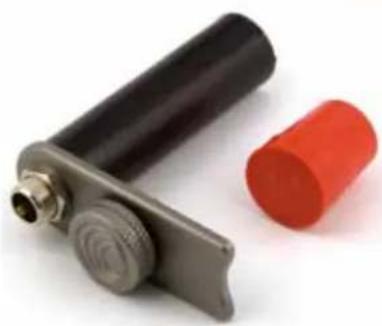
Close-up of a metallic cylindrical device with black and red components, no visible text or symbolsCE UK CA
Fill in for your records:
Serial Number:
Purchase Date:
Table of Contents
Introduction....3
General Technical Description ....4
Servo Bias Input....4
Digital Hybrid Wireless ^4 Technology....4
No Pre-Emphasis/De-Emphasis 4
Low Frequency Roll-Off....4
Input Limiter 4
Signal Encoding and Pilot Tone 5
Microprocessor Control....5
Compatibility Modes....5
Control Panel 5
Battery Options and Operating Time....5
Frequency Blocks 5
Circulator/Isolator 5
Controls and Functions....6
LCD Screen 6
Power LED 6
Power LED Off Feature....6
Audio Input Jack....6
AUDIO Button 6
FREQ Button 6
Up/Down Arrows....6
Antenna....7
Setup Screens....7
Audio Screen....7
Frequency Screen....7
Lock/Unlock Screen 7
Remote Control Operation 7
Configuring for Power Restore....7
Battery and Battery Eliminator Installation....8
Operating Instructions....8
Power Up and Boot Sequence....8
Power Down....8
Standby Mode....9
Selecting the Compatibility Mode....9
Setting Transmitter Operating Frequency....9
Locking or Unlocking the Controls 9
Adjusting Audio Level (Gain)....10
Locking or Unlocking the Controls ....10
Attaching and Removing the Microphone....10
5-Pin Input Jack Wiring....11
Installing the Connector: 11
Microphone Cable Termination for Non-Lectrosonics Microphones 12
Microphone RF Bypassing....13
Line Level Signals....13
Wiring Hookups for Different Sources....14
LectroRM....15
Troubleshooting....16
Straight Whip Antennas 18
Included Accessories....19
Optional Accessories....19
Specifications and Features....20
Service and Repair 21
Returning Units for Repair....21
Introduction
The SMB Series transmitters are the product of many years of engineering and experience in professional audio markets. The unique design provides several distinct features for professional applications:
• Superb, compandor-free audio quality
• Ultra-lightweight, corrosion resistant housing
• Water resistant seals for use in damp environments
- Programmable compatibility modes for use with a wide variety of different receivers
The Digital Hybrid Wireless ^® design (US Patent 7,225,135) combines 24-bit digital audio with analog FM resulting in a system that has the same operating range as analog systems, the same spectral efficiency as analog systems, the same long battery life as analog systems, plus the excellent audio fidelity typical of pure digital systems.
The transmitters feature the unique servo bias input circuitry with a standard TA5M type input jack for use with electret lavaliere mics, dynamic mics, or line level signals. A water resistant control panel with LCD, membrane switches and multi-color LEDs make input gain adjustments, frequency and compatibility mode selection quick and accurate, without having to view the receiver. The battery compartment accepts AA lithium or rechargeable batteries. The housings are machined from solid aluminum blocks to provide an extremely lightweight and rugged package. A special non-corrosive finish resists salt water exposure and perspiration in extreme environments.
The DSP-based design works with Euro version Digital Hybrid and IFB receivers.
The SMB/E01 and SMDB/E01 may be operated in:
| AT BE BG CH CY CZ | ||||
| DE DK EE FI FR GR | ||||
| HU IE IS LT LU LV | ||||
| MT NL NO PT RO SE | ||||
| SI SK UK |
The use of these transmittlers requires a license and is subject to national restrictions on frequency selection and channel spacing.


General Technical Description
Servo Bias Input
The voltage and current requirements of the wide variety of electret microphones used in professional applications has caused confusion and compromises in the wiring needed for wireless transmitters. To address this problem, the unique Servo Bias input circuit provides an automatically regulated voltage over a very wide range of current for compatibility with all microphones.
Digital Hybrid Wireless® Technology
All wireless links suffer from channel noise to some degree, and all wireless microphone systems seek to minimize the impact of that noise on the desired signal. Conventional analog systems use commanders for enhanced dynamic range, at the cost of subtle artifacts (typically “pumping” and “breathing”). Wholly digital systems defeat the noise by sending the audio information in digital form, at the cost of some combination of power, bandwidth and resistance to interference.
Digital Hybrid systems overcome channel noise in a dramatically new way, digitally encoding the audio in the transmitter and decoding it in the receiver, yet still sending the encoded information via an analog FM wireless link. This proprietary algorithm is not a digital implementation of an analog compandor but a technique that can be accomplished only in the digital domain, even though the inputs and outputs are analog.
Because it uses an analog FM link, the Digital Hybrid system enjoys all the benefits of conventional FM wireless systems and it does away with the analog compandor and its artifacts.
No Pre-Emphasis/De-Emphasis
The Digital Hybrid design results in a signal-to-noise ratio high enough to preclude the need for conventional pre-emphasis (HF boost) in the transmitter and de-emphasis (HF roll off) in the receiver. This eliminates the potential for distortion of signals with abundant high-frequency information.
Low Frequency Roll-Off
The low frequency roll-off can be set for a 3 dB down point at 35, 50, 70, 100, 120 and 150 Hz to control subsonic and very low frequency audio content in the audio. The actual roll-off frequency will vary slightly depending upon the low frequency response of the microphone.
Excessive low frequency content can drive the transmitter into limiting, or in the case of high level sound systems, can even cause damage to loudspeaker systems. The roll-off is normally adjusted by ear while listening as the system is operating.
Input Limiter
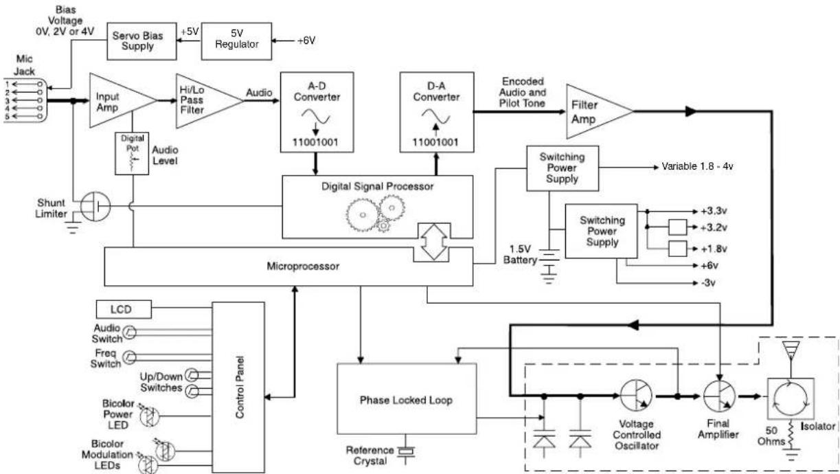
A DSP-controlled analog audio limiter is employed before the A-D converter. The limiter has a range of more than 30 dB for excellent overload protection. A dual release envelope makes the limiter acoustically transparent while maintaining low distortion. It can be thought of as two limiters in series, a fast attack and release limiter followed by a slow attack and release limiter. The limiter recovers quickly from brief transients, with no audible side effects, and also recovers slowly from sustained high levels to keep audio distortion low while preserving short term dynamics.
flowchart
graph TD
    A["Bias Voltage 0V, 2V or 4V"] --> B["Servo Bias Supply"]
    B --> C["+5V Regulator"]
    C --> D["5V"]
    D --> E["+6V"]
    E --> F["Audio Level"]
    F --> G["Digital Signal Processor"]
    G --> H["Digital Pot"]
    H --> I["Input Amp"]
    I --> J["Hi/Lo Pass Filter"]
    J --> K["A-D Converter"]
    K --> L["11001001"]
    L --> M["Digital Signal Processor"]
    M --> N["Microprocessor"]
    N --> O["Control Panel"]
    O --> P["LCD"]
    P --> Q["Audio Switch"]
    P --> R["Freq Switch"]
    P --> S["Up/Down Switches"]
    P --> T["Bicolor Power LED"]
    P --> U["Bicolor Modulation LEDs"]
    O --> V["Phase Locked Loop"]
    V --> W["Reference Crystal"]
    V --> X["Voltage Controlled Oscillator"]
    V --> Y["Final Amplifier"]
    Y --> Z["Isolator"]
    Z --> AA["50 Ohms"]
    Z --> AB["+3.3v"]
    Z --> AC["+3.2v"]
    Z --> AD["+1.8v"]
    Z --> AE["+6v"]
    Z --> AF["-3v"]
    G --> AG["Encoded Audio and Pilot Tone"]
    AG --> AH["Filter Amp"]
    AH --> AI["Switching Power Supply"]
    AI --> AJ["Variable 1.8 - 4v"]
Signal Encoding and Pilot Tone
In addition to controlling the limiter, the DSP also encodes the digitized audio from the A/D converter and adds an ultrasonic pilot tone to control the squelch in the receiver. A pilot tone squelch system provides a reliable method of keeping a receiver output muted when the squelch is active, even in the presence of significant interference. When the system is operating in the hybrid mode, a different pilot tone frequency is generated for each carrier frequency to prevent squelch problems in multi-channel systems.
Microprocessor Control
A microprocessor monitors user command inputs from the control panel buttons and numerous other internal signals. It works intimately with the DSP to ensure the audio is encoded according to the selected Compatibility Mode and that the correct pilot tone is added to the encoded signal.
Compatibility Modes
SMB transmitters are designed to operate with Lectrosonics Digital Hybrid receivers and will yield the best performance when doing so, however, due to the flexibility of digital signal processing, they can also operate with Lectrosonics Euro version IFB receivers.
Control Panel
The control panel includes four membrane switches and an LCD screen to adjust the operational settings. Multicolor LEDs are used to indicate audio signal levels for accurate gain adjustment and for battery status.
Battery Options and Operating Time
Switching power supplies convert regulated battery voltages to operate various circuit stages with maximum efficiency. With the variety of alkaline, lithium and rechargeable NiMH batteries available today in the AA format, there are many choices to maximize operating time or minimize cost as needed for any application.
The firmware “remembers” the power status when a battery fails or power is disconnected, so the transmitter will be turned on automatically when power is restored and previous settings will be enabled.
Frequency Blocks
Lectrosonics established a “block” numbering system years ago to organize the range of frequencies that are available. Legacy transmitters and receivers used two binary switches, each with 16 positions, to set the operating frequency. 16 × 16 = 256 , which defined the standard number of frequencies in each block to be 256. Since the steps between frequencies is 100 kHz, this results in a switching range of 25.6 MHz.
The lowest frequency in the switching range divided by 25.6 yields the block number. For example, 640.000 divided by 25.6 equals 25. In other words, block 25 starts at 640.000 MHz.
To determine what block a particular frequency falls into, divide the frequency and use the two significant digits to the left of the decimal. For example, to calculate the block for 580.500 MHz, divide 580 by 25.6, which equals 22.656, which indicates block 22.
Circulator/Isolator
The RF output circuit includes a one way circulator/isolator using a magnetically polarized ferrite. This device greatly reduces RF intermodulation produced when multiple transmitters are used in close proximity to one another (a meter or two, or less). The isolator also protects the output amplifier against static shock.
Controls and Functions

LCD Screen
The LCD is a numeric-type Liquid Crystal Display with screens for adjusting power, frequency, audio level and low frequency audio roll-off. The transmitter can be powered up with or without the RF output turned on. A countdown appears in the LCD when powering on and off, allowing the transmitter to be turned on without RF for adjustments, and to prevent accidentally turning it off with momentary button presses.
Power LED
The PWR LED glows green when the battery is good. The color changes to red at a mid-point of operating life, and will continue to glow red until the battery gets close to the end of its life. When the LED begins to blink red, there are only a few minutes remaining.
The exact point at which the LED turns red will vary with battery brand and condition, temperature and current drain. The LED is simply a reminder intended to catch your attention, not an exact indicator of remaining time.

line
| Time (Hours) | Voltage | | ------------ | ------- | | 0 | 1.5 | | 2 | 1.4 | | 4 | 1.3 | | 6 | 1.1 | | 8 | 0.8 |A NiMH rechargeable battery will give little or no warning when it is depleted because the voltage does not vary much during its operating life. If you wish to use NiMH batteries, we recommend trying fully charged batteries in the unit and using the battery timer feature available in most receivers to determine the available operating time.
A weak battery will sometimes cause the PWR LED to glow green immediately after the transmitter is turned on, but the battery will soon discharge to the point where the LED will turn red or the unit will turn off completely. When the transmitter is in SLEEP mode, the
LED blinks green every few seconds.
Power LED Off Feature
In normal operating mode, the DOWN and UP Arrow buttons may be used to turn the PWR LED indicators off and on. This setting does not persist through a power cycle nor does it affect the LCD backlight.
Audio Input Jack
The Servo Bias input circuitry accommodates virtually every lavaliere, handheld or shotgun microphone available, plus line level signals.
Modulation LEDs
Proper input gain adjustment is critical to ensure the best audio quality. Two bicolor LEDs will glow either red or green to accurately indicate modulation levels. The input circuitry includes a wide range DSP controlled limiter to prevent distortion at high input levels.
It is important to set the gain (audio level) high enough to achieve full modulation during louder peaks in the audio. The limiter can handle over 30 dB of level above full modulation, so with an optimum setting, the LEDs will flash red during use. If the LEDs never flash red, the gain is too low. In the table below, +0 dB indicates full modulation.
Signal Level -20 LED -10 LED
| Less than -20 dB | Off | Off | ||
| -20 dB to -10 dB | ● Green | ● Off | ||
| -10 dB to +0 dB | ● Green | ● Green | ||
| +0 dB to +10 dB | ● Red | ● Green | ||
| Greater than +10 db | ● Red | ● Red |
AUDIO Button
The AUDIO button is used to display the audio level and low frequency roll-off settings. The UP and DOWN arrows adjust the values.
The AUDIO button is also used with the FREQ button to enter standby mode and to turn the transmitter on or off.
FREQ Button
The FREQ Button displays the selected operating frequency and also toggles the LCD between displaying the actual operating frequency in MHz and a two-digit hexadecimal number that corresponds to the equivalent Lectrosonics Frequency Switch Setting.
The FREQ button is also used with the AUDIO button to enter standby mode and to turn the transmitter on or off.
Up/Down Arrows
The Up and Down arrow buttons are used to select the values on the various setup screens and to lock out the control panel. Pressing both arrows simultaneously enters the lock countdown. When an attempt is made to change a setting while the control panel is locked, a message will flash on the LCD reminding you that the unit is locked. Once locked, the buttons can only be unlocked by removing the battery, or via the RM remote control (if the remote function was enabled in the trans-
Antenna
The transmitter uses a whip antenna with a flexible woven, galvanized steel mesh cable and a standard SMA connector.
Setup Screens
Audio Screen

The Audio screen is used to adjust input gain from 0 to +44 dB, and the low frequency roll-off from 35 to 150 Hz. Repeatedly pressing the AUDIO button toggles back and forth between the two displays.
Press and hold the AUDIO button and use the Up and Down arrows to make adjustments.
Frequency Screen
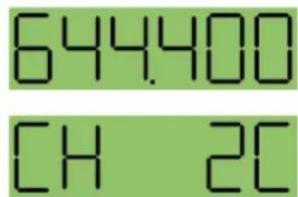
The Frequency Screen displays the operating frequency in MHz or as a two-digit hexadecimal number that corresponds to the equivalent Lectrosonics Frequency Switch Setting. Repeatedly pressing the
FREQ button toggles between the two displays. Press and hold the FREQ button and use the Up and Down arrows to select the frequency.
Lock/Unlock Screen
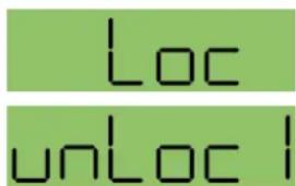
Simultaneously pressing and holding both the Up and Down arrow buttons during normal operation starts the Lock timer. The timer starts at three and counts down to zero. When
the timer reaches zero, the transmitter's controls are locked.
With the controls locked, the AUDIO and FREQ buttons can still be used to display current settings. Any attempt to change a setting by pressing either the Up or Down arrow button will result in an on-screen Loc reminder that the controls are locked. Remove the batteries to unlock the control panel.
Important: Once the transmitter is locked, it cannot be unlocked or powered off using the buttons. The only ways to unlock a locked transmitter are to remove the battery or unlock it using the RM remote control if this function is enabled on the transmitter.
Remote Control Operation

Remote Control Screens
The transmitters can be configured to respond to signals from the LectroRM app or to ignore them. This setting is accessed by holding down the Down arrow button while powering the transmitter on.
If a remote signal is detected but the transmitter is set to rc oFF, the message rc oFF will be displayed briefly on the transmitter's LCD, to confirm that a valid signal was received, but that the transmitter is not configured to respond to it.
Functions available from the remote control are:
- Audio Level
- Frequency
- Lock/Unlock Buttons
- Sleep/Wake (power saving mode)
- Tuning in 25 kHz steps
- Changing the low frequency roll-off setting
- Turning on/off the PWR and Audio LEDs
- Gain up/down functions
In sleep mode, the transmitter uses only 20% of the normal amount of battery drain. Sleep mode can only be invoked with the remote control, and can only be revoked with the remote control or by removing the battery. When in the sleep mode, the PWR LED blinks green every few seconds to indicate that the transmitter is asleep and not turned off.
Configuring for Power Restore
The Power Restore feature will turn the transmitter back on with the same settings that were enabled in the previous use after a battery is replaced or external power has been cycled off and back on.
1) Press and hold the Down Arrow Button then power on the transmitter by pressing the Audio and Freq buttons simultaneously.
2) Press AUDIO or FREQ key to scroll to the setting and then use the arrow keys to select PbAc 1 for ON or PbAc 0 for OFF.
Battery and Battery Eliminator Installation
Note: Standard zinc-carbon batteries marked "heavy-duty" or "long-lasting" are not adequate.
The battery status circuitry is designed for the voltage drop over the life of lithium batteries.
To install new batteries:
- Turn the Battery Cover Plate Thumbscrew counterclockwise a few turns until the door will rotate.
- Insert the new batteries into the housing. The positive (+) battery terminal goes into the transmitter first.
- Align the Battery Cover Plate and tighten the Battery Cover Plate Thumbscrew.

To install the battery eliminator, loosen the thumbscrew completely and remove the battery door. Insert the battery eliminator and tighten the thumbscrew.

Gore - Tex Registered trademark of W. L. Gore and Associates
Operating Instructions
Power Up and Boot Sequence
1) Ensure that good batteries are installed in the unit.
2) Simultaneously press and hold the AUDIO and FREQ buttons until the Power On Boot Sequence is initiated. As the unit turns on, the Modulation LEDs and PWR LED all glow red, then green, and then revert to normal operation.

The LCD displays a bootup sequence which consists of four screens similar to these examples:
Company Name: Lectro
Frequency Block (bXX) and
Firmware Version (rX.X): b21r1.1
Power Level Pr 50
Compatibility Mode: CP Hbr
Audio: Aud 22
Power Down

Initial Power Off Timer Screen
1) Simultaneously press and hold the AUDIO and FREQ buttons while observing that the word OFF appears in the LCD along with a counter.
2) Continue holding the buttons in until the counter reaches 0, and the unit will then turn off.
Note: If the AUDIO and FREQ buttons are released before the LCD goes blank at the end of the countdown, the unit will not turn off. Instead, it will stay energized and the display will return to the previous screen.
Standby Mode
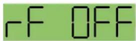
Standby Screen
Press the AUDIO and FREQ buttons briefly to place the unit in Standby Mode. In this mode the RF output is turned off so all setup
adjustments can be made without interfering with other systems operating in the same location. The screen displays rf OFF to remind the user that the unit is not transmitting.
While the unit is in the standby mode, access the setup screens using the AUDIO and FREQ buttons and make adjustments using the Up and Down arrows.
Selecting the Compatibility Mode

Digital Hybrid Wireless ^® compatibility mode
The transmitters will work with Digital Hybrid and IFB analog receivers. The unit automatically enters the Standby Mode when selecting compatibility.
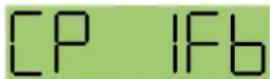
IFB compatibility mode
1) Set the receiver's audio controls to minimum.
2) From a power off condition, hold down the Up arrow, then simultaneously
press the AUDIO and FREQ buttons.
3) Press either AUDIO or FREQ button to select the compatibility screen and use the Up and Down arrows to select the desired mode.
The following Compatibility Modes are available:
• Digital Hybrid mode: CP Hbr
• IFB Series mode: CP IFb
4) Simultaneously press the AUDIO and FREQ buttons to exit this mode and turn off the power.
Adjusting the Low Frequency Roll-off
Repeatedly press the AUDIO button until the LF roll-off adjustment screen appears. Then press and hold the AUDIO button while selecting the desired roll-off frequency with the UP and DOWN arrows.
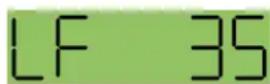

The roll-off frequency can be set to 35, 50, 70, 100, 120 and 150 Hz.
Setting Transmitter Operating Frequency
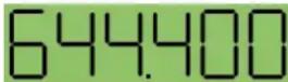
Frequency displayed in MHz

Frequency displayed as two-digit hexadecimal number
The frequency can be displayed either in MHz or as a two-digit hexadecimal number and can be set in the Standby Mode or when the transmitter is powered up. The hexadecimal numbering system is unique to Lectrosonics where two alphanumeric characters correspond to the left and right switch settings on
earlier analog transmitters that used mechanical rotary switches to adjust frequency. The hexadecimal notation is also easier to remember than a six character frequency and is supported on the receiver LCD.
1) Press the FREQ button to select either the MHz screen or the hexadecimal screen.
2) While holding the FREQ button, use the Up or Down arrow buttons to move the operating frequency up or down from the current setting.
Note: The operating frequency displayed on the LCD wraps as it reaches the upper or lower end of its range.
Locking or Unlocking the Controls

Control Panel Locked
The Lock mode protects the transmitter from accidental changes to its settings.
Simultaneously press both the Up and Down arrow
buttons to start the countdown timer. When the timer reaches zero, "Loc" is displayed and the controls are locked. Settings can be reviewed but not changed.
Once the transmitter is locked, it cannot be unlocked or powered off using the buttons. The only ways to unlock a locked transmitter are to remove the battery or unlock it using the remote control. The remote control will work only if the transmitter was previously configured to respond to the remote control. The unit will always power up in "unlocked" mode.
Adjusting Audio Level (Gain)
The control panel Modulation LEDs indicate the audio level and limiter activity. Once set, the transmitter's audio level setting should not be used to control the volume of your sound system or recorder levels. This gain adjustment matches the transmitter gain with the microphone's output level, the user's voice level and the position of the microphone. The audio input level (gain) is adjusted with the unit in the Standby Mode or while powered up while observing the LEDs.
It is desirable to set the gain so that some limiting occurs on louder peaks. The limiter is very transparent and its effect is not audible until the system is close to overload. In other words, don't be shy about turning up the gain. In fact, it is a good idea to turn the gain up to maximum and listen for distortion or compression to get a feel for how much headroom the system actually has.
Signal Level -20 LED -10 LED
| Less than -20 dB | ● Off Off | ● | ||
| -20 dB to -10 dB | ● Green Off | ● | ||
| -10 dB to +0 dB | Green | ● Green | ● | |
| +0 dB to +10 dB | Red | ● Green | ● | |
| Greater than +10 db | ● Red Red | ● | ||
Note: Different voices will usually require different gain settings, so check this adjustment as each new person uses the system. If several different people will be using the transmitter and there is not time to make the adjustment for each individual, adjust it for the loudest voice.
1) With the transmitter powered off, plug in the microphone and make sure the connector is firmly seated.
Warning: If the systems is powered up while connected to a live sound system, be careful to turn the sound system level down first or severe feedback can occur.
2) Place the transmitter in Standby Mode or turn it on for normal use.
3) Position the microphone in the location where it will be used in actual operation.
4) Observe the Modulation LEDs while speaking or singing into the microphone at the same voice level that will be used during use. While holding the AUDIO button, press the UP or DOWN arrow buttons until the both the -20 and -10 LEDs glow green, with the -20 LED occasionally flickering red. This will maximize the signal to noise ratio of the system with full modulation and provide subtle limiting to prevent overload and audible compression.
5) If the unit was set up in Standby Mode, it will be necessary to turn the transmitter off, then power it up again in normal operation so the RF output will be on. Then the other components in the sound or recording system can be adjusted.
Locking or Unlocking the Controls

Control Panel Locked
The Lock mode protects the transmitter from accidental changes to its settings.
Simultaneously press both the Up and Down arrow
buttons to start the countdown timer. When the timer reaches zero, "Loc" is displayed and the controls are locked. Settings can be reviewed but not changed.
Once the transmitter is locked, it cannot be unlocked or powered off using the buttons. The only ways to unlock a locked transmitter are to remove the battery or unlock it using the remote function. The remote function will work only if the transmitter was previously configured to respond. The unit will always power up in “unlocked” mode.
Attaching and Removing the Microphone
The flexible sleeve over the 5-pin plug on the microphone helps prevent dust and moisture from getting into the input jack. A flange is machined into the rim of the connector on the transmitter to help retain the sleeve after it is installed.
The following procedure simplifies the attachment and removal of the microphone to assure the sleeve is seated securely.
Align the pins on the plug and jack and insert the connector.

natural_image
Close-up of hands holding a handheld electronic device with a black cable and control buttons (no visible text or symbols)If the sleeve is pulled down and covering the connector, squeeze the end of the sleeve so you can feel the connector inside and press it into the jack until it latches.

Pinch and squeeze the sleeve near the flange and work it down with a kneading motion over the flange all the way around until it stays in place flush with the housing. Pull on the connector to make sure it is firmly latched.
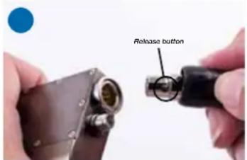
To remove the connector, pull the sleeve back to expose the black release button. Press the button to unlatch the plug.
5-Pin Input Jack Wiring
The wiring diagrams included in this section represent the basic wiring necessary for the most common types of microphones and other audio inputs. Some microphones may require extra jumpers or a slight variation on the diagrams shown.
It is virtually impossible to keep completely up to date on changes that other manufacturers make to their products, thus you may encounter a microphone that differs from these instructions. If this occurs please call our toll-free number listed under Service and Repair in this manual or visit our web site at: www.lectrosonics.com

Audio input jack wiring:
- PIN 1 Shield (ground) for positive biased electret lavaliere microphones. Shield (ground) for dynamic microphones and line level inputs.
- PIN 2 Bias voltage source for positive biased electret lavaliere microphones.
- PIN 3 Low impedance microphone level input for dynamic microphones. Also accepts hand-held electret microphones provided the microphone has its own built-in battery.
- PIN 4 Bias voltage selector for Pin 3. Pin 3 voltage (0, 2 or 4 volts) depends on Pin 4 connection.
Pin 4 tied to Pin 1: 0 V
Pin 4 Open: 2 V
Pin 4 to Pin 2: 4 V
- PIN 5 High impedance, line level input for tape decks, mixer outputs, musical instruments, etc.

Note: If you use the dust boot, remove the rubber strain relief that is attached to the TA5F cap, or the boot will not fit over the assembly.
Installing the Connector:
1) If necessary, remove old connector from microphone cable.
2) Slide Rubber Boot onto microphone cable with the large end facing away from the microphone. (See illustration above.)
3) If necessary, slide the 1/8-inch black shrink tubing onto the microphone cable. (This tubing is needed for some cables to ensure the cable fits snugly in the rubber boot.)
4) Use the resistors and connector included with this kit to configure the TA5F to your particular microphone. A length of .065 OD clear tubing is included if insulating the resistor leads or shield wire is necessary. (Remove rubber strain relief from connector backshell by pulling it out of the backshell.)
5) Slide the Strain Relief over the TA5F Insert and crimp as shown to the right. Then insert the TA5F Insert and Strain Relief in the TA5F Latchlock. Screw the TA5F Flex Relief onto the TA5F Latchlock.
6) If needed, position and shrink the 1/8-inch shrink tubing on the microphone cable, then slide the Rubber Boot down over the TA5F connector.
Microphone Cable Termination
TA5F Connector Assembly

flowchart
graph LR
    A["Component 1"] --> B["Arrow Left"]
    B --> C["Component 2"]
    C --> D["Arrow Right"]
    D --> E["Component 3"]
    E --> F["Arrow Left"]
    F --> G["Component 4"]
    G --> H["Arrow Right"]
Mic Cord Stripping Instructions

Crimping to Shield and Insulation

Strip and position the cable so that the clamp can be crimped to contact both the mic cable shield and the insulation. The shield contact reduces noise with some microphones and the insulation clamp increases ruggedness.
NOTE: This termination is intended for UHF transmitters only. VHF transmitters with 5-pin jacks require a different termination. Lectrosonics lavaliere microphones are terminated for compatibility with VHF and UHF transmitters, which is different than what is shown here.
Microphone RF Bypassing
When used on a wireless transmitter, the microphone element is in the proximity of the RF coming from the transmitter. The nature of electret microphones makes them sensitive to RF, which can cause problems with the microphone/transmitter compatibility. If the electret microphone is not designed properly for use with wireless transmitters, it may be necessary to install a chip capacitor in the mic capsule or connector to block the RF from entering the electret capsule.
Some mics require RF protection to keep the radio signal from affecting the capsule, even though the transmitter input circuitry is already RF bypassed (see schematic diagram).
If the mic is wired as directed, and you are having difficulty with squealing, high noise, or poor frequency response, RF is likely to be the cause.
The best RF protection is accomplished by installing RF bypass capacitors at the mic capsule. If this is not possible, or if you are still having problems, capacitors can be installed on the mic pins inside the TA5F connector housing.
Line Level Signals
The normal hookup for line level signals is:
- Signal Hot to pin 5
- Signal Gnd to pin 1
- Pin 4 jumped to pin 1
This allows signal levels up to 3V RMS to be applied without limiting.
If more headroom is needed, insert a 20 k resistor in series with pin 5. Put this resistor inside the TA5F connector to minimize noise pickup.


3 WIRE MIC2 WIRE
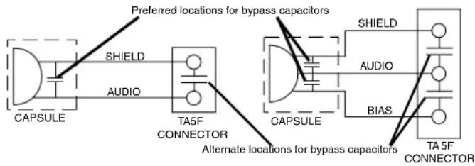
Install the capacitors as follows: Use 330 pF capacitors. Capacitors are available from Lectrosonics. Please specify the part number for the desired lead style.
Leaded capacitors: P/N 15117
Leadless capacitors: P/N SCC330P
All Lectrosonics lavaliere mics are already bypassed and do not need any additional capacitors installed for proper operation.
Wiring Hookups for Different Sources
In addition to the microphone and line level wiring hook-ups illustrated below, Lectrosonics makes a number of cables and adapters for other situations such as connecting musical instruments (guitars, bass guitars, etc.) to the transmitter. Visit www.lectrosonics.com and click on Accessories, or download the master catalog.
A lot of information regarding microphone wiring is also available in the FAQ section of the web site at:
http://www.lectrosonics.com
Hover over Support and click on FAQs. Follow the instructions to search by model number or other search options.
Compatible Wiring for Both Servo Bias Inputs and Earlier Transmitters:
Fig. 1
2 VOLT POSITIVE BIAS 2-WIRE ELECTRET

Fig. 2
4 VOLT POSITIVE BIAS 2-WIRE ELECTRET

Fig. 3 - DPA Microphones
DANISH PRO AUDIO MINIATURE MODELS

Fig. 4
2 VOLT NEGATIVE BIAS 2-WIRE ELECTRET
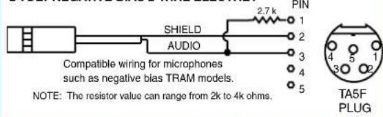
Fig. 5 - Sanken COS-11 and others
4 VOLT POSITIVE BIAS 3-WIRE ELECTRET WITH EXTERNAL RESISTOR

Fig. 6
LO-Z MICROPHONE LEVEL SIGNALS

Fig. 7
BALANCED AND FLOATING LINE LEVEL SIGNALS

Fig. 8
UNBALANCED LINE LEVEL SIGNALS

Simple Wiring - Can ONLY be used with Servo Bias Inputs:
Servo Bias was introduced in 2005 and all transmitters with 5-pin inputs have been built with this feature since 2007.
Fig. 9
2 VOLT POSITIVE BIAS 2-WIRE ELECTRET
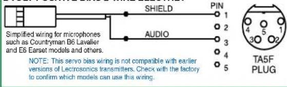
Fig. 10
2 VOLT NEGATIVE BIAS 2-WIRE ELECTRET
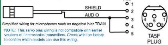
Fig. 11
4 VOLT POSITIVE BIAS 3-WIRE ELECTRET

LectroRM
By New Endian LLC
LectroRM is a mobile application for iOS and Android operating systems. Its purpose is to remotely control Lectrosonics Transmitters, including:
- SM Series
• WM
• L Series
The app remotely changes settings on the transmitter through the use of encoded audio tones, which when received by the attached microphone, will alter the configured setting. The app was released by New Endian, LLC in September 2011. The app is available for download and sells for \$25 on the Apple App Store and Google Play Store.
LectroRM's remote control mechanism is the use of an audio sequence of tones (dweedles) that are interpreted by the transmitter as a configuration change. The settings available in LectroRM are:
- Audio Level
- Frequency
- Sleep Mode
- Lock Mode
User Interface
The user interface involves selecting the audio sequence related to the desired change. Each version has an interface for selecting the desired setting and the desired option for that setting. Each version also has a mechanism to prevent accidental activation of the tone.
iOS
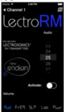

The iPhone version keeps each available setting on a separate page with the list of options for that setting. On iOS, the “Activate” toggle switch must be enabled to show the button which will then activate the audio. The iOS version’s default orientation is upside-down but can be configured to orient right-side up. The purpose for this is to orient the device’s speaker, which is at the bottom of the device, closer to the transmitter microphone.
Android


The Android version keeps all settings on the same page and allows the user to toggle between the activation buttons for each setting. The activation button must be long pressed to activate. The Android version also allows users to keep a configurable list of full sets of settings.
Activation
For a transmitter to respond to remote control audio tones, the transmitter must meet certain requirements:
- The transmitter must not be turned off; it can however be in sleep mode.
- The transmitter must have firmware version 1.5 or later for Audio, Frequency, Sleep and Lock changes.
- The transmitter microphone must be within range.
- The transmitter must be configured to enable remote control activation.
Please be aware this app is not a Lectrosonics product. It is privately owned and operated by New Endian LLC, www.newendian.com.
Troubleshooting
Before going through the following chart, be sure that you have a good battery in the transmitter. It is important that you follow these steps in the sequence listed.
SYMPTOM POSSIBLE CAUSE
TRANSMITTER PWR LED OFF 1) Battery is inserted backwards or dead.
2) Transmitter not powered up. (See Operating Instructions, Power UP and Boot Sequence.)
TRANSMITTER PWR LED BLINKS GREEN EVERY FEW SECONDS, TRANSMITTER DOES NOT RESPOND OTHERWISE 1) Transmitter has been put to sleep by remote.
Either use the remote function to wake it up again or remove and reinsert the transmitter's battery.
AUDIO LEVEL LEDs NOT LIGHTING 1) Gain control set to minimum.
2) Battery is dead or installed backwards. Check PWR LED.
3) Mic capsule is damaged or malfunctioning.
4) Mic cable damaged or mis-wired.
RECEIVER RF INDICATOR OFF 1) Transmitter not turned on, or is in Standby Mode.
2) Transmitter battery is dead.
3) Receiver antenna missing or improperly positioned.
4) Transmitter and receiver not on same frequency. Check switches/display on transmitter and receiver.
5) Transmitter and receiver not on same frequency block.
6) Operating range is too great.
7) Defective transmitter antenna.
NO SOUND (OR LOW SOUND LEVEL), RECEIVER INDICATES PROPER AUDIO MODULATION
1) Receiver output level set too low.
2) Receiver output disconnected, or cable defective or mis-wired.
3) Sound system or recorder input is turned down.
DISTORTED SOUND 1) Transmitter gain (audio level) is far too high. Check audio level LEDs and receiver audio levels during use.
2) Receiver output may be mismatched with the sound system or recorder input. Adjust output level on receiver to the correct level for the recorder, mixer or sound system. (Use the receiver's Tone function to check level.)
3) Transmitter is not set to same frequency as receiver. Check that operating frequency on receiver and transmitter match.
4) Receiver/Transmitter Compatibility Mode mismatched.
EXCESSIVE FEEDBACK
1) Transmitter gain (audio level) too high. Check gain adjustment
and/or reduce receiver output level.
2) Talent standing too close to speaker system.
3) Mic is too far from user's mouth.
SYMPTOM POSSIBLE CAUSE
HISS AND NOISE -- AUDIBLE DROPOUTS 1) Transmitter gain (audio level) far too low.
2) Receiver antenna missing or obstructed.
3) Transmitter antenna broken or missing.
4) Operating range too great.
5) Signal interference. Turn off transmitter. If receiver's signal strength indicator does not drop to nearly zero, this indicates an interfering signal may be the problem.
Try a different operating frequency.
"Loc" APPEARS IN DISPLAY WHEN ANY BUTTON IS PRESSED
1) Control Panel is locked. (See Operating Instructions, Locking
and Unlocking the Control Panel.)
"Hold" APPEARS IN DISPLAY WHEN ARROW BUTTONS ARE PRESSED
1) Reminder that it is necessary to hold down the AUDIO or FREQ button to make adjustments to the audio gain or frequency settings.
"PLL" APPEARS IN DISPLAY 1) Indication that the PLL is not locked. This is a serious condition
that requires factory repair. It may be possible to operate on another frequency far removed from the one that was selected when the condition was indicated.
TRANSMITTER WON'T RESPOND TO REMOTE
1) If LCD blinks "rc oFF", transmitter has not been configured to respond to the remote function. See "Remote Operation" on page 16 for instructions on how to configure.
2) If LCD blinks “- - - - - - ”, transmitter is already set as requested by remote.
3) If transmitter does not respond at all, try moving closer to the transmitter.
4) Make sure transmitter is not in Sleep mode.
Straight Whip Antennas
The Lectrosonics AMMKIT provides the parts to make an antenna with a standard SMA connector for any of the available frequency blocks. Cut the whip according to the lengths in the table below or by laying the antenna over the template to determine the correct length. Be sure to check the scale of your printout by measuring the length of the line below the drawing.
The frequency range and/or block is marked on the outside of the transmitter housing.
Unmarked antennas can be identified by laying them on the template below. Be sure to verify that a print out is at 100% by checking the length of the line below the antenna drawing.

Note: Check the scale of your printout. This line should be 6.00 inches long (152.4 mm).
| BLOCK | FREQUENCY RANGE | CAP/SLEEVE COLOR | ANTENNA WHIP LENGTH |
| 470 470.1 | 100 - 495.600 Black w/ | Label 5.67" | |
| 19 486.4 | 00 - 511.900 Black w/ | Label 5.23" | |
| 20 512.0 | 00 - 537.500 Black w/ | Label 4.98" | |
| 21 537.6 | 00 - 563.100 Brown w/ | Label 4.74" | |
| 22 563.2 | 00 - 588.700 Red w/ | Label 4.48" | |
| 23 588.8 | 00 - 614.300 Orange w/ | Label 4.24" | |
| 606 606.0 | 00 - 631.500 (Use Block 24 Ant) | ||
| 24 614.4 | 00 - 639.900 Yellow w/ | Label 4.01" | |
| 25 640.0 | 00 - 665.500 Green w/ | Label 3.81" | |
| 26 665.6 | 00 - 691.100 Blue w/ | Label 3.62" | |
| 27 691.2 | 00 - 716.700 Violet (Pink) w/ | Label 3.46" | |
| 28 716.8 | 00 - 742.300 Grey w/ | Label 3.31" | |
| 29 742.4 | 00 - 767.900 White w/ | Label 3.18" | |
| 30 768.0 | 00 - 793.500 Black-w/ | Label 3.08" | |
| 31 793.6 | 00 - 819.100 Black-w/ | Label 2.99" | |
| 32 819.2 | 00 - 844.700 Black-w/ | Label 2.92" | |
| 33 844.8 | 00 - 861.900 Black-w/ | Label 2.87" |
Included Accessories
SMB:
PSM Leather pouch with integrated belt clip

natural_image
Black leather wallet with transparent cover (no visible text or symbols)SMDB:
PSMD Leather pouch with integrated belt clip

natural_image
Black leather wrist strap device (no visible text or symbols)35924 Themal insulating pad for SMDB

natural_image
Close-up of a black electronic device with white top and blue connectors (no visible text or symbols)Place Thermal insulation pad on back of unit, as pictured.
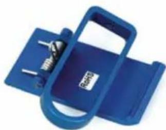
SMBCUPSL Spring-loaded machined aluminum clip
natural_image
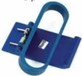
Blue plastic electronic device with a strap and metal clip, no visible text or symbolsSMDBCSL Spring-loaded machined aluminum clip
natural_image
Blue plastic object with a U-shaped handle and metal clip, no visible text or symbolsOptional Accessories
SMKITTA5 Connector kit for SMV series transmitters, 5-pin TA5F plug with sleeve

natural_image
Close-up of a black cable with multiple connectors and a red connector (no text or symbols visible)SMBCDN Machined, wire belt clip for SMV transmitters, antenna down

natural_image
Blue metal chain tag with a loop handle, isolated on white background (no text or symbols)SMBCUP Machined, wire belt clip for SMV transmitters, antenna up

natural_image
Blue metal chain hook with attached metal bracket (no text or symbols)SMDBC Machined, wire belt clip for SMQV and transmitters

natural_image
Blue plastic chain tag with metal hook, isolated on white background (no text or symbols)Specifications and Features
Operating frequencies:
| Block 470 | 470.100 - 495.600 |
| Block 19 | 486.400 - 511.900 |
| Block 20 | 512.000 - 537.500 |
| Block 21 | 537.600 - 563.100 |
| Block 22 | 563.200 - 588.700 |
| Block 23 | 588.800 - 614.300 |
| Block 24 | 614.400 - 639.900 |
| Block 25 | 640.000 - 665.500 |
| Block 26 | 665.600 - 691.100 |
E02 Additional Frequencies:
| Block 27 | 691.200 - 716.700 |
| Block 28 | 716.800 - 742.300 |
| Block 29 | 742.400 - 767.900 |
| Block 30 | 768.000 - 793.500 |
| Block 31 | 793.600 - 819.100 |
| Block 32 | 819.200 - 844.700 |
| Block 33 | 844.800 - 861.900 |
NOTE: It's the user's responsibility to select the approved frequencies for the region where the transmitter is operating.
Frequency range:
256 frequencies in 100 kHz steps for one
25.5 MHz wide block
Channel Spacing: 100 kHz
Type of Modulation: FM
Frequency selection: Control panel mounted membrane switches
RF Power output: E01: 50 mW (nominal)
E02: 10 mW
Compatibility Modes: E01: Digital Hybrid Wireless® and IFB
E02: Digital Hybrid Wireless®, Mode 3, and IFB
Pilot tone: 25 to 32 kHz; 3 kHz deviation in hybrid mode
Frequency stability: ± 0.002%
Deviation: ± 50 kHz max. in hybrid mode
Spurious radiation: Compliant ETSI EN 300 422-1
Equivalent input noise:
-125 dBV, A-weighted
Input level:
If set for dynamic mic: 0.5 mV to 50 mV before limiting. Greater than 1 V with limiting.
If set for electret lavaliere mic: 1.7 uA to 170 uA before limiting. Greater than 5000 uA (5 mA) with limiting.
Line level input: 17 mV to 1.7 V before limiting. Greater than 50 V with limiting.
Input impedance:
Dynamic mic: 300 Ohms
Electret lavaliere: Input is virtual ground with servo adjusted
constant current bias
Line level: 2.7 k Ohms
Input limiter:
Soft limiter, 30 dB range
Bias voltages:
Fixed 5 V at up to 5 mA
Selectable 2 V or 4 V servo bias for any electret lavaliere.
Gain control range: 40 dB; panel mounted membrane switches
Modulation indicators:
-20, -10, 0, +10 dB referenced to full modulation.
Dual bicolor LEDs indicate modulation of
Controls:
Control panel with LCD and four membrane switches.
Low frequency roll-off:
Adjustable from 35 to 150 Hz.

line
| Time (s) | Urea (dB) | Mn-150 Hz (dB) | |---|---|---| | 20 | -13.0 | -12.5 | | 30 | -8.0 | -7.5 | | 100 | -4.0 | -3.5 | | 2k | -12.0 | -11.5 |Audio Frequency Response:
35 Hz to 20 kHz, +/-1 dB (The low frequency roll-off is adjustable - see graph above)
Signal to Noise Ratio (dB): (overall system, 400 Series mode)
| SmartNR | No Limiting | w/ Limiting |
| OFF 103.5 | 108.0 | |
| NORMAL | 107.0 | 111.5 |
| FULL | 108.5 | 113.0 |
(Note: the dual envelope "soft" limiter provides exceptionally good handling of transients using variable attack and release
time constants. The gradual onset of limiting in the design begins below full modulation, which reduces the measured figure for SNR without limiting by 4.5 dB)
Total Harmonic Distortion:
0.2% typical (400 Series mode)
Audio Input Jack:
Switchcraft 5-pin locking (TA5F)
Antenna:
Flexible, unbreakable steel cable.
Batteries:
1.5 Volt AA lithium or rechargeable
NiMH recommended
Battery Life:
SMB: 2 hours (alkaline); 7.25 hours (lithium), 5 hours with 2500mAh NiMH
SMDB: 6 hours (alkaline); 14.5 hours (lithium), 8.5 hours with 2500mAh NiMH
Weight:
SMB: 2.7 oz.. (75.9 grams) with lithium battery
SMDB: 3.7 oz.. (105 grams) with lithium
batteries
Overall Dimensions:
SMB: 2.3 x 1.8 x 0.64 inches (not including microphone)
58 x 46 x 16 mm
(not including microphone)
SMDB: 2.3 × 2.4 × 0.64 inches
(not including microphone)
58 x 60 x 16 mm
(not including microphone)
Specifications subject to change without notice.
CE1313 ⚠
Service and Repair
If your system malfunctions, you should attempt to correct or isolate the trouble before concluding that the equipment needs repair. Make sure you have followed the setup procedure and operating instructions. Check the interconnecting cables and then go through the Troubleshooting section in this manual.
We strongly recommend that you do not try to repair the equipment yourself and do not have the local repair shop attempt anything other than the simplest repair. If the repair is more complicated than a broken wire or loose connection, send the unit to the factory for repair and service. Don't attempt to adjust any controls inside the units. Once set at the factory, the various controls and trimmers do not drift with age or vibration and never require readjustment.
There are no adjustments inside that will make a malfunctioning unit start working.
LECTROSONICS' Service Department is equipped and staffed to quickly repair your equipment. In warranty repairs are made at no charge in accordance with the terms of the warranty. Out-of-warranty repairs are charged at a modest flat rate plus parts and shipping. Since it takes almost as much time and effort to determine what is wrong as it does to make the repair, there is a charge for an exact quotation. We will be happy to quote approximate charges by phone for out-of-warranty repairs.
Returning Units for Repair
For timely service, please follow the steps below:
A. DO NOT return equipment to the factory for repair without first contacting us by email or by phone. We need to know the nature of the problem, the model number and the serial number of the equipment. We also need a phone number where you can be reached 8 A.M. to 4 P.M. (U.S. Mountain Standard Time).
B. After receiving your request, we will issue you a return authorization number (R.A.). This number will help speed your repair through our receiving and repair departments. The return authorization number must be clearly shown on the outside of the shipping container.
C. Pack the equipment carefully and ship to us, shipping costs prepaid. If necessary, we can provide you with the proper packing materials. UPS is usually the best way to ship the units. Heavy units should be “double-boxed” for safe transport.
D. We also strongly recommend that you insure the equipment, since we cannot be responsible for loss of or damage to equipment that you ship. Of course, we insure the equipment when we ship it back to you.
Lectrosonics USA:
Mailing address: Shipping address: Telephone:
Lectrosonics, Inc. Lectrosonics, Inc. (505) 892-4501
PO Box 15900 581 Laser Rd. (800) 821-1121 Toll-free
Rio Rancho, NM 87174 Rio Rancho, NM 87124 (505) 892-6243 Fax
USA USA
Web: E-mail:
www.lectrosonics.com sales@lectrosonics.com
Lectrosonics Canada:
| Mailing Address: | Telephone: | E-mail: | ||
| 720 Spadina Avenue, Suite 600 (877) 753-2876 | (416) 596-2202 | Sales: | colinb@lectrosonics.com | |
| Toronto, Ontario M5S 2T9 | Toll-free Service: joeb@lectrosonics.com (877-7LECTRO) | |||
| (416) | 596-6648 | Fax | ||
Self-Help Options for Non-Urgent Concerns
Our Facebook groups and weblists are a wealth of knowledge for user questions and information. Refer to:
Lectrosonics General Facebook Group: https://www.facebook.com/groups/69511015699
D Squared, Venue 2 and Wireless Designer Group: https://www.facebook.com/groups/104052953321109
The Wire Lists: https://lectrosonics.com/the-wire-lists.html
LIMITED ONE YEAR WARRANTY
The equipment is warranted for one year from date of purchase against defects in materials or workmanship provided it was purchased from an authorized dealer. This warranty does not cover equipment which has been abused or damaged by careless handling or shipping. This warranty does not apply to used or demonstrator equipment.
Should any defect develop, Lectrosonics, Inc. will, at our option, repair or replace any defective parts without charge for either parts or labor. If Lectrosonics, Inc. cannot correct the defect in your equipment, it will be replaced at no charge with a similar new item. Lectrosonics, Inc. will pay for the cost of returning your equipment to you.
This warranty applies only to items returned to Lectrosonics, Inc. or an authorized dealer, shipping costs prepaid, within one year from the date of purchase.
This Limited Warranty is governed by the laws of the State of New Mexico. It states the entire liability of Lectrosonics Inc. and the entire remedy of the purchaser for any breach of warranty as outlined above. NEITHER LECTROSONICS, INC. NOR ANYONE INVOLVED IN THE PRODUCTION OR DELIVERY OF THE EQUIPMENT SHALL BE LIABLE FOR ANY INDIRECT, SPECIAL, PUNITIVE, CONSEQUENTIAL, OR INCIDENTAL DAMAGES ARISING OUT OF THE USE OR INABILITY TO USE THIS EQUIPMENT EVEN IF LECTROSONICS, INC. HAS BEEN ADVISED OF THE POSSIBILITY OF SUCH DAMAGES. IN NO EVENT SHALL THE LIABILITY OF LECTROSONICS, INC. EXCEED THE PURCHASE PRICE OF ANY DEFECTIVE EQUIPMENT.
This warranty gives you specific legal rights. You may have additional legal rights which vary from state to state.

- Table of Contents
- Introduction
- General Technical Description
- Servo Bias Input
- Digital Hybrid Wireless® Technology
- No Pre-Emphasis/De-Emphasis
- Low Frequency Roll-Off
- Input Limiter
- Signal Encoding and Pilot Tone
- Microprocessor Control
- Compatibility Modes
- Control Panel
- Battery Options and Operating Time
- Frequency Blocks
- Circulator/Isolator
- Controls and Functions
- LCD Screen
- Power LED
- Power LED Off Feature
- Audio Input Jack
- Modulation LEDs
- AUDIO Button
- FREQ Button
- Up/Down Arrows
- Antenna
- Setup Screens
- Audio Screen
- Frequency Screen
- Lock/Unlock Screen
- Remote Control Operation
- Configuring for Power Restore
- Battery and Battery Eliminator Installation
- Operating Instructions
- Power Up and Boot Sequence
- Power Down
- Standby Mode
- Selecting the Compatibility Mode
- Adjusting the Low Frequency Roll-off
- Setting Transmitter Operating Frequency
- Locking or Unlocking the Controls
- Adjusting Audio Level (Gain)
- Attaching and Removing the Microphone
- 5-Pin Input Jack Wiring
- Audio input jack wiring:
- Installing the Connector:
- Microphone Cable Termination
- Microphone RF Bypassing
- Line Level Signals
- Wiring Hookups for Different Sources
- http://www.lectrosonics.com
- Compatible Wiring for Both Servo Bias Inputs and Earlier Transmitters:
- Simple Wiring - Can ONLY be used with Servo Bias Inputs:
- LectroRM
- By New Endian LLC
- User Interface
- Activation
- Troubleshooting
- SYMPTOM POSSIBLE CAUSE
- EXCESSIVE FEEDBACK
- TRANSMITTER WON'T RESPOND TO REMOTE
- Straight Whip Antennas
- Included Accessories
- SMB:
- SMDB:
- Optional Accessories
- Specifications and Features
- Service and Repair
- Returning Units for Repair
- Lectrosonics USA:
- Lectrosonics Canada:
- Self-Help Options for Non-Urgent Concerns
- LIMITED ONE YEAR WARRANTY
Brand : Lectrosonics
Model : SMB/E01
Category : Radio transmitter