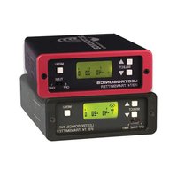
IFBT4 - Radio transmitter Lectrosonics - Free user manual and instructions
Find the device manual for free IFBT4 Lectrosonics in PDF.


| Product Type | IFB Transmitter (Bodypack) |
| Dimensions | 3.0 x 2.4 x 0.8 in (76 x 61 x 20 mm) |
| Weight | 4.2 oz (119 g) with battery |
| Power Source | Two AA alkaline batteries or external DC 5-9V |
| Frequency Range | 470-614 MHz (UHF) |
| RF Output Power | 100 mW (typical) |
| Audio Input | 3.5 mm TRS balanced line/mic level |
| Audio Frequency Response | 50 Hz - 15 kHz ±1 dB |
| Modulation | FM, ±75 kHz deviation |
| Controls | Power switch, gain control, channel select, audio mute |
| Indicators | Power/Battery LED, Audio level LED |
| Compatibility | Lectrosonics IFB receivers (IFBR1, etc.) |
| Battery Life | Approximately 8 hours with alkaline batteries |
| Operating Temperature | -10°C to 50°C (14°F to 122°F) |
| Construction | Machined aluminum with black anodized finish |
| Accessories Included | Antenna, belt clip, AA batteries (2) |
| Mounting Options | Belt clip, optional shoe mount |
| Compliance | FCC, CE, RoHS |
| Warranty | 2 years limited |
Frequently Asked Questions - IFBT4 Lectrosonics
User questions about IFBT4 Lectrosonics
0 question about this device. Answer the ones you know or ask your own.
Ask a new question about this device
Download the instructions for your Radio transmitter in PDF format for free! Find your manual IFBT4 - Lectrosonics and take your electronic device back in hand. On this page are published all the documents necessary for the use of your device. IFBT4 by Lectrosonics.
USER MANUAL IFBT4 Lectrosonics
Synthesized UHF IFB Transmitter
IFBT4, IFBT4/E01, IFBT4/X

Featuring Digital Hybrid Wireless™ Technology
U.S. Patent 7,225,135

Follow Us On:



Fill in for your records:
Serial Number:
Purchase Date:


Opinion Number: KOR1222
DIRECTIVE 1999/5/EC
NOTIFIED BODY STATEMENT OF OPINION
Bay Area Compliance Laboratories Corp.
| Date of Issue: | 2009-03-02 |
| Applicant Details: | Lectonomics, Inc. |
| 561 Laser Bond, Rio Rancón, NM 87174, USA | |
| Model: | JFHT4/EDI |
| Equipment Type: | FM UHF Transmitter |
| Serial Number: | B2011 |
| Network Interferent: | N/A |
| Frequency Range: | Low Band: 470.1-495.6 MHzMid Band: 665.6-691.1 MHzHigh Band: 844.8-862.0 MHz |
| RF Output Power: | 5Hz/8 (ERF) |
| Medulation Type: | FM |
| Antenna Type: | External Antenna (BNC Connection) |
| Notified Body (131): | Bar Area Compliance Laboratories Corp.1274 Antibased Air, Sunnyvale, CA 94089, USATel: 1-(408)732-9162 Fax: 1-(408)732-9164www.hndcorp.com |
| Essential Requirements | Specifications/Standards | Report Identification | Results |
| Radio Spectrum, Article 3.2 | EN 300-422 v1.2.2 (2008-03) | R0012222-422 | Compliant |
| EMC, Article 3.1(b) | EN 301-489-9 v1.4.1 (2007-11)EN 301-489-1 v1.8.1 (2008-04) | R0012222-12 | Compliant |
| Safety, Article 3.3(a) | EN 60956-1: 2001+ A11.1-2004 | R0012222-3 | Compliant |
Our opinion in accordance with Annex IV of Council Directive 1999/5-EC on mobile equipment and telecommunications equipment and the mutual recognition of their conformity is that the apparatus identified above complies with the requirements of that directive stated above.
Making it is recommended that the proposal has the CT work, the nominal body number(s) as depicted to the right, only what all the nominal improvements have been met and a Nomofactor's Declaration of Cochraneity (ICP) (DHL) has been filed with the European Commission. Number of attendees to this statement: 1
CE1313①
Authorized by

Bay Area Compliance Laboratory Corp. 1274 Arvilwood Ave, Sunnyvale, CA 94089, U.S.A. Tel: (408)732-9162 Fax: (408)732-9164

EU Declaration of Conformity
LECTROSONICS, INC.
581 Laser Road
Rio Rancho, NM 87124 USA
Declare under our sole responsibility that the following products,
IFBT4/E01 Transmitter, table top and rack mount
to which this Declaration relates, are in conformity with the following requirements:
Radio Spectrum: Article 3.2, EN 300 422 v1.2.2 (2008-03), BACL reports R0812222-422
EMC: Article 3.1(b), EN 301 489-9 v1.4.1 (2007-11), EN 301 489-1 v1.8.1 (2008-04) BACL reports R0812222-12
Safety: Article 3.1(a), EN 60950-1:2001+A11.1:2004 BACL reports R0812222-3


Postal address:
LECTROSONICS, INC., PO Box 15900, Rio Rancho, NM 87174 USA
Table of Contents
General Technical Description ....4
Introduction....4
Audio Input Interface 4
Input Limiter 4
Audio DSP and Noise Reduction 5
Pilot Tone Squelch System....5
Frequency Agility 5
Power Delay 5
Microcontroller....5
Transmitter 5
Antenna System....5
Front Panel Controls and Functions....6
IFBT4 Front Panel 6
OFF/TUNE/XMIT Switch....6
Power Up Sequence....6
Main Window 6
Frequency Window....6
Audio Input Gain Window....6
Setup Window....6
ROLLOFF Setup Screen 6
COMPAT Setup Screen....7
IFBT4 Menu Diagram....7
TUNING Setup Screen....8
Lock/Unlock Panel Buttons....8
Rear Panel Controls and Functions....9
IFBT4 Rear Panel....9
XLR Jack 9
MODE Switches....9
Power Input Connector 9
Antenna....9
Installation and Operation....10
Operating Notes 10
Supplied Accessories....11
Optional Accessories....12
UHF Transmitter Antenna Specifications....13
Specifications....14
Troubleshooting....15
Service and Repair 16
Returning Units for Repair....16
Introduction
The IFBT4 IFB transmitter brings DSP capability and a convenient LCD interface to the popular Lectrosonics IFB product line. Replacing the venerable IFBT1 transmitter, the IFBT4 retains the same physical size and is fully interchangeable with its predecessor in terms of audio, RF and power interfaces. Along with providing peerless audio quality with wide frequency response and dynamic range in Nu Hybrid mode, the technology used in the IFBT4 includes compatibility modes for Lectrosonics Mode 3 and IFB receivers.
The IFBT4 features a graphics type backlit LCD display with a menu system similar to those featured in our 400 Series receivers. The IFBT4 can be “Locked” to prevent a user from changing any settings but still allow browsing of the current settings.
The IFBT4 can be powered from any external DC source of 6 to 18 Volts at 200 milliamps maximum or from the provided 12 Volt power supply with a locking power connector. The unit has an internal self-resetting fuse and reverse polarity protection.
The IFBT4 is housed in a machined aluminum case with a tough electrostatic powder coating. The front and rear panels are anodized aluminum with laser etched engraving. The included antenna is a right angle, 14 wavelength monopole with a BNC connector, constructed of polymer coated flexible steel cable.
These features, along with the 250 milliwatt RF output and a wide range of selectable audio input types and levels, make the IFBT4 an excellent choice for long range IFB applications and other long range wireless audio needs.
Audio Input Interface
The standard 3 pin XLR connector on the rear panel handles all audio inputs. The four DIP switches allow setting the input sensitivity for low levels, such as microphone inputs, or for high levels, such as line inputs, balanced or unbalanced. The switches also offer special settings to provide the proper input configurations to match to Clear Com, RTS1, and RTS2 intercom systems. Pin 1 of the XLR input connector is normally connected to ground but an internal jumper can be moved if a floating input is desired.
While the XLR input does not offer phantom power, it is fully compatible with standard 48 Volt phantom power. Phantom supplied microphones may be connected to the IFBT4 without the need for DC isolation.
A user-selectable low frequency roll-off can be set for 35 Hz or 50 Hz. The recommended 50 Hz default setting helps to remove wind and traffic noise, air conditioner rumble, and other sources of undesired low frequency audio. The 35 Hz setting offers a fuller range of sound in the absence of adverse conditions.
Input Limiter
A DSP-controlled analog audio limiter is employed before the analog-to-digital converter. The limiter has a range of more than 30 dB for excellent overload protection. A dual release envelope makes the limiter acoustically transparent while maintaining low distortion. It can be thought of as two limiters in series: a fast attack and release limiter followed by a slower attack and release limiter. The dual release limiter recovers quickly from brief transients but recovers more slowly from sustained
IFBT4 Transmitter Block Diagram
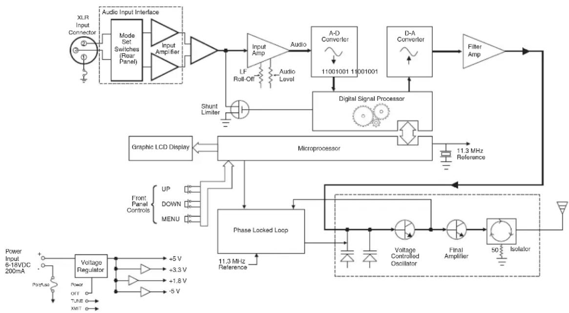
flowchart
graph TD
    A["XLR Input Connector"] --> B["Audio Input Interface"]
    B --> C["Mode Set Switches (Rear Panel)"]
    C --> D["Input Amplifier"]
    D --> E["Input Amp"]
    E --> F["Audio Level"]
    F --> G["A-D Converter 11001001 11001001"]
    G --> H["Digital Signal Processor"]
    H --> I["Filter Amp"]
    I --> J["Output"]
    K["Shunt Limiter"] --> L["Amplifier"]
    L --> M["Microprocessor"]
    M --> N["Phase Locked Loop"]
    N --> O["Voltage Controlled Oscillator"]
    O --> P["Final Amplifier"]
    P --> Q["Isolator"]
    Q --> R["Output"]
    S["Graphic LCD Display"] --> M
    T["Front Panel Controls UP DOWN MENU"] --> N
    U["Power Input 6-18VDC 200mA"] --> V["Voltage Regulator +5V +3.3V +1.8V -5V"]
    V --> W["Power OFF TIME XMT"]
high levels, keeping audio distortion low while preserving short term dynamic changes. When the audio meter on the LCD display widens slightly as it reaches zero, limiting is indicated. When the zero changes to a letter C, severe limiting and/or clipping is indicated.
Audio DSP and Noise Reduction
Lectrosonics IFB systems use a single band compa- dor and pre-emphasis for exceptional IFB audio quality. The IFBT4 performs these traditionally analog functions entirely in the digital domain, maintaining historical compatibility while requiring fewer adjustments. When the IFBT4 is configured for compatibility with other types of wireless systems, the DSP stops IFB companding and instead performs the appropriate audio processing for the chosen mode. The Nu Hybrid mode offers objectively superior audio performance and is recommended when the receiver is capable of supporting it.
Pilot Tone Squelch System
Lectrosonics IFB systems use a special “pilot tone” so that valid IFB signals can be distinguished from RF interference. During normal operation, an IFB receiver will listen for the distinctive pilot tone, remaining silent (squelched) until the pilot tone is detected. The pilot tone is located well above audio frequencies and is never passed through to the receiver’s audio output.
The benefit of the pilot tone squelch system is that the receiver will remain muted until it receives the pilot tone from the matching transmitter, even if a strong interfering RF signal is present on the carrier frequency of the system.
When the IFBT4 is operated in compatibility modes other than IFB, it generates pilot tones as appropriate for the chosen mode.
Frequency Agility
The IFBT4 transmitter uses a synthesized, frequency selectable main oscillator. The frequency is extremely stable over a wide temperature range and over time. The transmitter's standard tuning range covers 256 frequencies in 100kHz steps over a 25.6 MHz band. This flexibility significantly helps avoid interference problems in mobile or traveling applications.
Power Delay
When powering the transmitter on and off, and when switching between the XMIT and TUNE modes, intelligent circuitry adds brief delays in order to allow time for circuits to stabilize, both locally and in the matching receiver. These delays prevent clicks, thumps or feedback from entering the sound system.
Microcontroller
The microcontroller oversees most system operations, including RF frequency and output, DSP audio functions, buttons and display, and more. User settings are stored in non-volatile memory, so they are retained even when the power is turned off.
Transmitter
The IFBT4 transmitter operates at a high RF power level to ensure a clean signal free of dropouts and noise. All transmitter circuits are buffered and filtered for excellent spectral purity. The IFBT4's clean signal reduces the chances for interference in multiple transmitter installations.
Antenna System
The 50 Ohm BNC output connector will work with standard coaxial cabling and remote antennas.
IFBT4 Front Panel

OFF/TUNE/XMIT Switch
OFF Turns the unit off.
TUNE Allows all functions of the transmitter to be set up, without transmitting. The operating frequency may only be selected in this mode.
XMIT Normal operating position. The operating frequency may not be changed in this mode, though other settings may be changed, so long as the unit isn't "Locked."
Power Up Sequence
When power is first turned on, the front panel LCD display steps through the following sequence.
- Displays Model and frequency block number (e.g. IFBT4 BLK 25).
- Displays installed firmware version number (e.g. VERSION 1.0).
- Displays the current compatibility mode setting (e.g. COMPAT IFB).
- Displays the Main Window.
Main Window
The Main window is dominated by an audio level meter, which displays the current audio modulation level in real
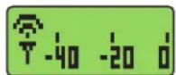
time. In TUNE mode, a blinking capital "T" is displayed in the lower left corner to remind the user that the unit is not yet transmitting. In XMIT mode, the blinking "T" is replaced by an antenna icon.
Audio limiting is indicated when the audio bargraph extends all the way to the right and widens somewhat. Clipping is indicated when the zero in the lower right corner changes to a capital “C”.
The Up and Down buttons are disabled in this Window.
Frequency Window
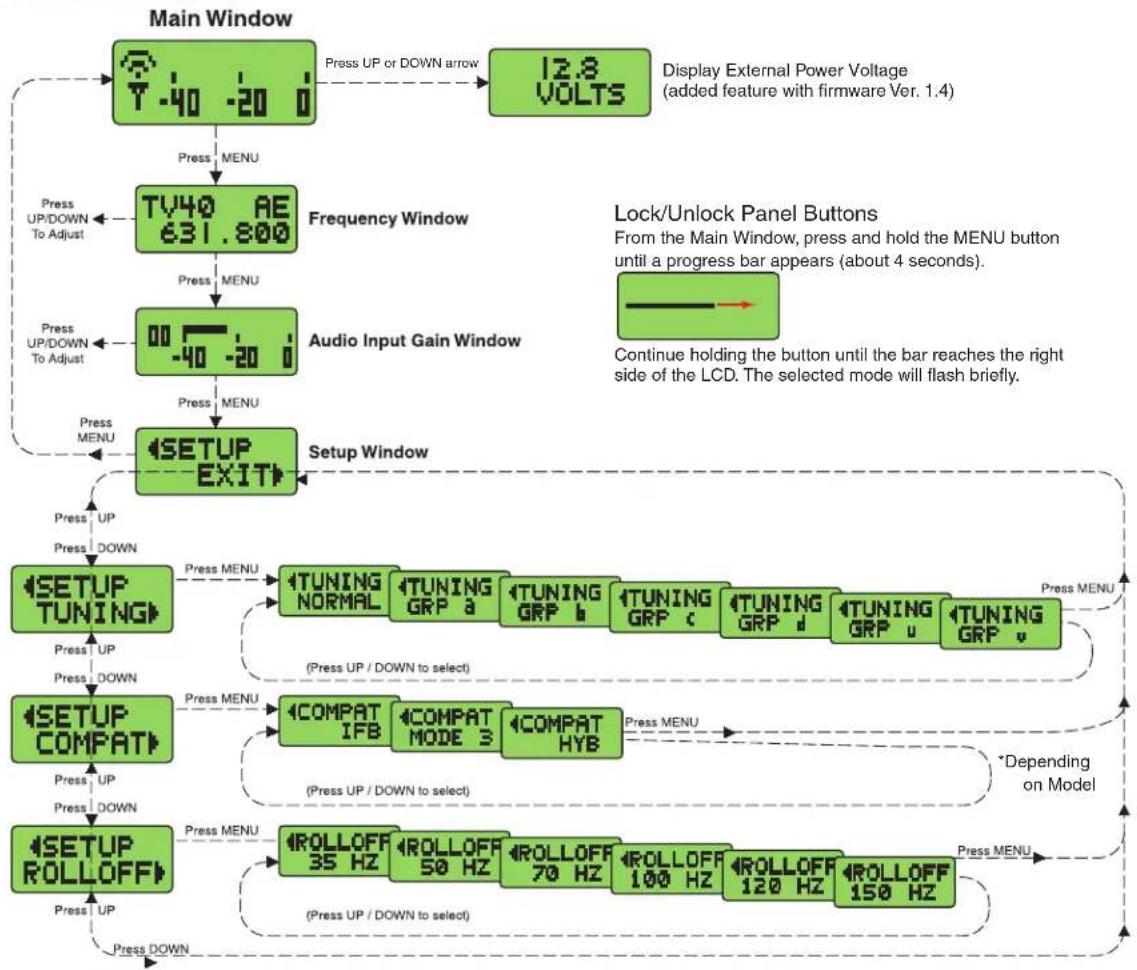
Pressing the MENU button once from the Main window navigates to the Frequency

window. The Frequency window displays the current operating frequency in MHz, as well as the standard Lectrosonics hex code for use with transmitters equipped with hex
switches. Also displayed is the UHF television channel to which the selected frequency belongs.
In XMIT mode, it is not possible to change the operating frequency.
In TUNE mode, the Up and Down buttons may be used to select a new frequency.
If the TUNING mode is set to NORMAL, the Up and Down buttons navigate in single channel increments, and MENU+Up and MENU+Down move 16 channels at a time. In any of the various group tuning modes, the currently selected group identifier is displayed to the left of the hex code, and the Up and Down buttons navigate among the frequencies in the group. In factory group tuning modes A thru D, MENU+Up and MENU+Down jump to the highest and lowest frequencies in the group. In user group tuning modes U and V, MENU+Up and MENU+Down permit access to frequencies not currently in the group.
Pressing and holding the Up or Down button invokes an autorepeat function, for faster tuning.
Audio Input Gain Window
Pressing the MENU button once from the Frequency window navigates to the Audio Input Gain window. This window
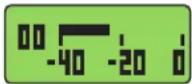
greatly resembles the Main window, with the exception that the current audio input gain setting is displayed in the upper left corner. The Up and Down buttons may be used to alter the setting while reading the realtime audio meter to determine what setting works best.
The gain range is -18 dB to +24 dB with 0 dB nominal center. The reference for this control can be changed with the rear panel MODE switches. See the Installation and Operation section for more information on the MODE switches.
Setup Window
Pressing the MENU button once from the Audio Input Gain window navigates to the Setup window. This window

contains a menu which permits access to various setup screens.
Initially the active menu item is EXIT. Pressing the Up and Down keys permits navigation among the remaining menu items: TUNING, COMPAT and ROLLOFF.
Pressing the MENU button selects the current menu item. Selecting EXIT navigates back to the Main window. Selecting any other item navigates to the associated setup screen.
ROLLOFF Setup Screen

The ROLLOFF setup screen controls the low frequency audio response of the IFBT4 by moving the 3 dB corner of a 4 pole lowpass digital filter. The 50 Hz setting is the default, and should be used whenever wind noise, HVAC rumble, traffic noise or other low frequency sounds may degrade the quality of the audio. The 35 Hz setting may be used in the absence of adverse conditions, for a fuller bass response.
Press MENU to return to the Setup window.
COMPAT Setup Screen
The COMPAT setup screen selects the current compatibility mode, for interoperation with various types of receivers.
US:
Nu Hybrid - This mode offers the best audio quality and is recommended if your receiver supports it.
IFB - Lectrosonics IFB compatibility mode. This is the default setting and is the appropriate setting to use with a compatible IFB receiver.
MODE 3 - Compatible with certain non-Lectrosonics receivers. (Contact factory for more information.)
NOTE: If your Lectrosonics receiver does not have Nu Hybrid mode, use Euro Digital Hybrid Wireless® (EU Dig. Hybrid).
E/01:
IFB - Lectrosonics IFB compatibility mode. This is the default setting and is the appropriate setting to use with the Lectrosonics IFBR1A or a compatible IFB receiver.
400 - Lectrosonics 400 Series. This mode offers the best audio quality and is recommended if your receiver supports it.
X:
IFB - Lectrosonics IFB compatibility mode. This is the default setting and is the appropriate setting to use with the Lectrosonics IFBR1A or a compatible IFB receiver.
400 - Lectrosonics 400 Series. This mode offers the best audio quality and is recommended if your receiver supports it.
100 - Lectrosonics 100 Series compatibility mode.
200 - Lectrosonics 200 Series compatibility mode.
MODE 3 and MODE 6 - Compatible with certain non-Lectrosonics receivers.
Press MENU to return to the Setup window.
IFBT4 Menu Diagram
flowchart
graph TD
    A["Main Window"] --> B["T-40 -20 i"]
    B --> C["Press UP or DOWN arrow"]
    C --> D["12.8 VOLTS"]
    D --> E["Display External Power Voltage (added feature with firmware Ver. 1.4)"]
    E --> F["TV40 AE 631.800"]
    F --> G["Frequency Window"]
    G --> H["Press UP/DOWN To Adjust"]
    H --> I["00 -40 -20 i"]
    I --> J["Audio Input Gain Window"]
    J --> K["Press MENU"]
    K --> L["SETUP EXIT"]
    L --> M["Setup Window"]
    M --> N["SETUP TUNING"]
    N --> O["Press UP"]
    O --> P["Press DOWN"]
    P --> Q["SETUP COMPAT"]
    Q --> R["Press UP"]
    R --> S["Press DOWN"]
    S --> T["SETUP ROLLOFF"]
    T --> U["Press UP"]
    U --> V["Press DOWN"]
    V --> W["SETUP TUNING NORMAL"]
    W --> X["(Press UP / DOWN to select)"]
    X --> Y["COMPAT IFB"]
    Y --> Z["(Press UP / DOWN to select)"]
    Z --> AA["SETUP ROLLOFF 35 Hz"]
    AA --> AB["(Press UP / DOWN to select)"]
    AB --> AC["SETUP ROLLOFF 50 Hz"]
    AC --> AD["(Press UP / DOWN to select)"]
    AD --> AE["SETUP ROLLOFF 70 Hz"]
    AE --> AF["(Press UP / DOWN to select)"]
    AF --> AG["SETUP ROLLOFF 100 Hz"]
    AG --> AH["(Press UP / DOWN to select)"]
    AH --> AI["SETUP ROLLOFF 120 Hz"]
    AI --> AJ["(Press UP / DOWN to select)"]
    AJ --> AK["SETUP ROLLOFF 150 Hz"]
    AK --> AL["(Press UP / DOWN to select)"]
    AL --> AM["SETUP ROLLOFF 35 Hz"]
    AM --> AN["(Press UP / DOWN to select)"]
    AN --> AO["SETUP ROLLOFF 50 Hz"]
    AO --> AP["(Press UP / DOWN to select)"]
    AP --> AQ["SETUP ROLLOFF 70 Hz"]
    AQ --> AR["(Press UP / DOWN to select)"]
    AR --> AS["SETUP ROLLOFF 100 Hz"]
    AS --> AT["(Press UP / DOWN to select)"]
    AT --> AU["SETUP ROLLOFF 120 Hz"]
    AU --> AV["(Press UP / DOWN to select)"]
    AV --> AW["SETUP ROLLOFF 150 Hz"]
    AW --> AX["(Press UP / DOWN to select)"]
    AX --> AY["SETUP ROLLOFF 35 Hz"]
    AY --> AZ["(Press UP / DOWN to select)"]
    AZ --> BA["SETUP ROLLOFF 50 Hz"]
    BA --> BB["(Press UP / DOWN to select)"]
    BB --> BC["SETUP ROLLOFF 70 Hz"]
    BC --> BD["(Press UP / DOWN to select)"]
    BD --> BE["SETUP ROLLOFF 100 Hz"]
    BE --> BF["(Press UP / DOWN to select)"]
    BF --> BG["SETUP ROLLOFF 120 Hz"]
    BG --> BH["(Press UP / DOWN to select)"]
    BH --> BI["SETUP ROLLOFF 150 Hz"]
TUNING Setup Screen
SETUP TUNING
The TUNING setup screen allows selection of one of four factory set fre-
quency groups (Groups A through D), two user programmable frequency groups (Groups U and V) or the choice to not use groups at all.
In the four factory set frequency groups, eight frequencies per group are preselected. These frequencies are chosen to be free of intermodulation products. (Refer to receiver manual for more information).
In the two user programmable frequency groups, up to 16 frequencies can be programmed per group.
Note: The TUNING Setup Screen only selects the tuning mode (NORMAL or Group tuning) and not the operating frequency. Actual operating frequencies are chosen through the Frequency Window.
Press MENU to return to the Setup window.
Lock/Unlock Panel Buttons
To enable or disable the control panel buttons, navigate to the Main Window and press and hold the MENU button for about 4 seconds. Continue holding the button as a progress bar extends across the LCD. When the bar reaches the right side of the screen, the unit will toggle to the opposite locked or unlocked mode.
Frequency Window Behavior, based on TUNING mode selections
If NORMAL tuning mode is selected, the Up and Down buttons select the operating frequency in single channel (100 kHz) increments and the MENU+Up and MENU+Down shortcuts tune in 16 channel (1.6 MHz) increments.
There are two classes of group tuning: factory preset groups (Grp A through D) and user programmable frequency groups (Grp U and V).
In any of the group modes, a lower case a, b, c, d, u or v will be displayed to the immediate left of the transmitter switch settings in the Frequency window. The letter identifies the selected factory or user tuning group. Any time the currently tuned frequency is not in the current group, this group identification letter will blink. Any time the currently tuned frequency is in the current tuning group, the group tuning mode indicator will give a steady (non-blinking) indication.
In any of the group modes, the Up and Down buttons navigate among the selected intermod-free frequencies in the group. In factory groups (A through D), the MENU+Up and MENU+Down shortcuts jump to the first and last frequencies in the group. In user groups (U and V), MENU+Up and MENU+Down permit access to frequencies not already in the group.
User Programmable Frequency Group Behavior
The user programmable frequency groups “U” or “V” work very similarly to the factory groups with a few exceptions. The most obvious difference is the ability to add or remove frequencies from the group. Less obvious is the behavior of a user programmable frequency group with only one entry, or with no entries.
A user programmable frequency group with only one entry continues to display the single frequency stored in the group no matter how many times the Up or Down buttons are pressed (provided the MENU button is not pressed at the same time). The “U” or “V” will not blink.
A user programmable frequency group with no entries reverts to non-group-mode behavior, i.e., access is allowed to all available frequencies in the selected receiver module's frequency block. When there are no entries, the "U" or "V" will of course blink. However, once a frequency has been added to the tuning group, this behavior changes to group-mode behavior where the MENU button must be pressed and held while either the Up or Down buttons are pressed to access frequencies that are not part of the current tuning group.
Adding/Deleting User Programmable Frequency Group Entries
Note: Each User Programmable Frequency Group ("u" or "v") has separate contents. We recommend that you consider the larger issue of frequency coordination prior to adding frequencies in order to minimize potential intermodulation problems.
- Start from the Frequency window and verify that a lower case "u" or "v" is present next to the transmitter switch settings.
- While pressing and holding the MENU button press either the Up or Down button to move to one of the 256 available frequencies in the block. Whenever the selection comes to rest on a frequency that is in the current group, the group tuning mode indicator (letter "u" or "v") will give a steady indication. On frequencies that are not in the group, the indicator will blink.
- To add or remove the displayed frequency from the group, hold down the MENU button while pressing and holding the Up button. The group tuning mode indicator will stop blinking to show that the frequency has been added to the group, or begin blinking to indicate that the frequency has been removed from the group.
Rear Panel Controls and Functions
IFBT4 Rear Panel
XLR Jack
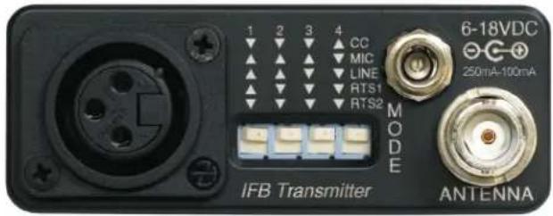
A standard XLR female jack accepts a variety of input sources depending on the setting of the rear panel MODE switches. XLR pin functions can be changed to suit the source depending on the positions of the individual switches. For detailed information on the setting of these switches see the Installation and Operation section.
MODE Switches
The MODE switches allow the IFBT4 to accommodate a variety of input source levels by changing the input sensitivity and the pin functions of the input XLR jack. Marked on the rear panel are the most common settings. Each setting is detailed below. Switches 1 and 2 adjust the XLR pin functions while switches 3 and 4 adjust the input sensitivity.
| Name | 1 | 2 | 3 | 4 | XLR | Pins | Balanced | Input Sensitivity |
| CC | ▼ | ▼ | ▼ | ▲ | 3 = Audio No -10 dBu | |||
| 1 = Common | ||||||||
| MIC | ▲ | ▲ | ▲ | ▼ | 2 = Hi | Yes | -42 dBu | |
| 3 = Lo | ||||||||
| 1 = Common | ||||||||
| LINE | ▲ | ▲ | ▼ | ▼ | 2 = Hi | Yes | 0 dBu | |
| 3 = Lo | ||||||||
| 1 = Common | ||||||||
| RTS1 | ▲ | ▼ | ▼ | ▼ | 2 = Hi | No | 0 dBu | |
| 1 = Common | ||||||||
| RTS2 | ▼ | ▼ | ▼ | ▼ | 3 = Hi | No | 0 dBu | |
| 1 = Common | ||||||||
Power Input Connector
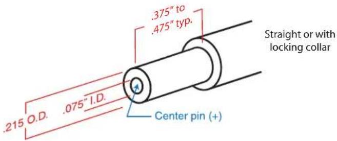
The IFBT4 is designed to be used with the DCR12/A5U external (or equivalent) power source. The nominal voltage to operate the unit is 12 VDC, although it will operate at voltages as low as 6 VDC and as high as 18 VDC. External power sources must be able to supply 200 mA continuously.
The connector dimensions are shown below. Lectrosonics P/N 21425 has a straight back shell. P/N 21586 has a locking collar.
Antenna
The ANTENNA connector is a standard 50 ohm BNC type for use with standard coaxial cabling and remote antennas.
Installation and Operation
1) The IFBT4 transmitter is shipped with pin 1 of the XLR input connector tied directly to ground. If a floating input is desired, a Ground Lift Jumper is provided. This jumper is located inside the unit
on the PC board near the rear panel XLR jack. For floating input, open the unit and move the Ground Lift Jumper to the desired location.

Ground Position

Lift Position
Location of Ground Lift Jumper:

natural_image
Close-up of an electronic circuit board with visible traces, wires, and components (no readable text or symbols)2) Set the MODE switches on the rear panel to match the specific input source to be used. (See MODE Switches.)
3) Insert the power supply plug into the 6-18 VDC jack on the rear panel.
4) Insert the microphone or other audio source XLR plug into the input jack. Ensure that the pins are aligned and that the connector locks into place.
5) Attach the antenna (or antenna cable) to the BNC connector on the rear panel.
6) Set the OFF/TUNE/XMIT switch to TUNE.
7) Press the MENU button to display the Frequency Window and adjust the transmitter to the desired frequency with the front panel Up and Down buttons.
8) Position the microphone. The microphone should be placed where it will be located during actual use.
9) Use the MENU button to navigate to the Audio Input Gain Window. While speaking at the same voice level that will be present during actual use, observe the audio meter display. Use the Up and Down buttons to adjust the audio input gain so that the meter reads close to 0 dB, but only rarely exceeds 0 dB (limiting).
10) Once the transmitter audio gain has been set, the receiver and other components of the system can be turned on and their audio levels adjusted. Set the power switch on the IFBT4 transmitter to XMIT and adjust the associated receiver and sound system level as required.
Note: There will be a delay between the moment the transmitter is energized and the actual appearance of audio at the receiver output. This intentional delay eliminates turn-on thumps, and is controlled by the pilot tone squelch system.
Operating Notes
The AUDIO LEVEL control should not be used to control the volume of the associated receiver. This gain adjustment is used to match the IFBT4 input level to the incoming signal from the sound source to provide full modulation and maximum dynamic range, not to set the volume of the associated receiver.
If the audio level is too high — the audio metering will exceed the 0 dB level too frequently. This condition may reduce the dynamic range of the audio signal.
If the audio level is too low — the audio metering will be too far below the 0 dB level. This condition may cause hiss and noise in the audio, or pumping and breathing in the background noise.
The input limiter will handle peaks over 15 dB above full modulation, regardless of the gain control setting. Occasional limiting is often deemed desirable, indicating that the gain is correctly set and the transmitter is fully modulated for optimum signal to noise ratio. Different voices will usually require different audio input gain settings, so check this adjustment as each new person uses the system. If several different people will be using the transmitter and there is not time to make the adjustment for each individual, adjust it for the loudest voice.
Supplied Accessories
DCR12/A5U
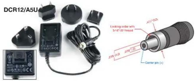
AC power supply for IFBT4 transmitters; 100-240 V, 50/60 Hz, 0.3 A input, 12 VDC regulated output; 7-foot cord with LZR threaded locking plug and interchangeable blades/posts for use in Europe, UK, Australia and USA (sold separately).
21586
DC16A Pigtail power cable, LZR stripped & tinned.
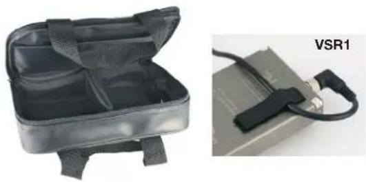
CMINI
A soft sided, padded and zippered carrying case for compact wireless systems
VSR1
Velcro cable strain relief. One piece mounts to receiver and the cable is held between that piece and a mating cover piece.
35679
Lectrosonics screwdriver and adjustment tool for setting transmitter gain and roll-off pots as well as for setting the frequency switches on some older receivers and transmitters.
A500RAxx
UHF antenna, right angle BNC. Specify block such as A500RA-24 for block 24. These antennas can be used one block above and below the specified block. Color coded tip per ANSI resistor code. See page 13 for specification information.

natural_image
Two views of a black plastic device with straps and a close-up of a USB cable labeled VSR1 (no text or symbols on the device itself)
natural_image
Close-up of a white LED with printed label 'LECTROSONICS' and logo, no visible text beyond the product name.
natural_image
Two black and red coaxial cable connectors with metallic connectors (no text or symbols visible)Optional Accessories
SNA600
Collapsible dipole antenna that adjusts over a wide frequency range. Ideal for situations where a full 360 degree receiving pattern is required as opposed to a directional pattern.
ALP Series Antennas
ALP500, ALP620 & ALP650 Shark Fin style Log Periodic Dipole Array (LPDA) Antennas that provide a useful directional pattern over a broad frequency bandwidth. Ideal for portable applications including temporary setups for field production.
ALPKIT
Stainless steel kit for mounting SNA600 and ALP Series antennas on photo and video tripods, lighting equipment, and standard microphone stands.
ARG15
A 15 foot antenna cable of standard RG-58 coax cable with BNC connectors at each end. Loss of 1 to 2 dB with 0.25" diameter.
ARG25/ARG50/ARG100
An antenna cable of Belden 9913F low-loss coax cable with BNC connectors at each end. Double shielded, flexible, 50 Ohms, with a foamed polyethylene dielectric. Lower loss (1.6 to 2.3 dB) with somewhat less weight than standard RG-8 with the same 0.400" diameter. Available in 25, 50 and 100 foot lengths.
RMP195
4 channel rack mount for up to four IFBT4 transmitters. Rocker switch included to work as a master power switch if desired.
21425
6 ft. long power cord; coaxial to stripped & tinned leads. Coaxial plug: ID-.080"; OD-.218"; Depth-.5". Fits all compact receiver models that use CH12 power supply.
21472
6 ft. long power cord; coaxial to stripped & tinned leads. Right angle coaxial plug: ID-.075"; OD-.218"; Depth-.375". Fits all compact receiver models that use CH12 power supply.

natural_image
Coiled black cable with connectors and metallic connectors, no visible text or symbols
natural_image
Black rack-mounted server unit labeled RMP195 with visible internal compartments and mounting brackets (no text beyond label)

UHF Transmitter Antenna Specifications

Measure from this edge of the housing
BLOCK FREQUENCY CAP ANTENNA RANGE COLOR WHIP LENGTH
Lectrosonics A500RA UHF transmitter antennas follow the color code specifications in the chart below to identify operating frequency block range. (The frequency block range is engraved on the outside housing for each individual transmitter.) If a situation exists whereby the antenna is defective and the antenna cap is missing, refer to the following chart to determine the correct replacement antenna.
| 470 470.100 - 495.600 Black 4.73” | ||
| 19 486.400 - 511.900 Black 4.51” | ||
| 20 512.000 - 537.500 Black 4.05” | ||
| 21 537.600 - 563.100 Brown 3.80” | ||
| 22 563.200 - 588.700 Red 3.48” | ||
| 23 588.800 - 614.300 Orange 3.36” | ||
| 24 614.400 - 639.900 Yellow 3.22” | ||
| 25 640.000 - 665.500 Green 3.00” | ||
| 26 665.600 - 691.100 Blue | 2.79” | |
| 27 691.200 - 716.700 Violet (Pink) | 2.58” | |
| 28 716.800 - 742.300 Grey | 2.44” | |
| 29 742.400 - 767.900 White | 2.33” | |
| 30 768.000 - 793.500 Black w/label | 2.27” | |
| 31 793.600 - 819.100 Black w/label | 2.22” | |
| 32 819.200 - 844.700 Black w/label | 1.93” | |
| 33 844.800 - 861.900 Black w/label | 1.88” | |
| 944 944.100 - 951.900 Black w/label | 1.57” |
Specifications
Operating Frequencies (MHz):
US
Block 470 470.100 - 495.600
Block 19 486.400 - 511.900
Block 20 512.000 - 537.500
Block 21 537.600 - 563.100
Block 22 563.200 - 588.700
Block 23 588.800 - 607.900
Block 944 944.100 - 951.900
NOTE: It's the user's responsibility to select the approved frequencies for the region where the transmitter is operating.
E01 and X
Block 470 470.100 - 495.600
Block 19 486.400 - 511.900
Block 20 512.000 - 537.500
Block 21 537.600 - 563.100
Block 22 563.200 - 588.700
Block 23 588.800 - 607.900 and 614.100 - 614.300
Block 24 614.400 - 639.900
Block 25 640.000 - 665.500
Block 26 665.600 - 691.100
Block 27 691.200 - 716.700
Block 28 716.800 - 742.300
Block 29 742.400 - 767.900
Block 30 768.000 - 793.500 (E01 Only)
Block 31 793.600 - 819.100 (E01 Only)
Block 32 819.200 - 844.700 (E01 Only)
Block 33 844.800 - 861.900 (E01 Only)
Block 606 606.000 - 631.500 (E01 Only)
Block 944 944.100 - 951.900 (X Only)
Channel Spacing: 100 kHz (0.1 MHz)
RF Power Output: US, X: 250 mW E01: 50 mW
Pilot tone: US: 25 to 32 kHz; 3.5 kHz deviation (Nu Hybrid mode) E01: 29.997 kHz; 2 kHz deviation (IFB Mode), 25 to 32 kHz
(Digital Hybrid Mode
X: 29.997 kHz IFB & 100 MODE, 32.765kHz 200 MODE, 400 MODE step selected
Spurious Radiation: US:Compliant with ETSI EN 300 422-1 v1.4.2 E01: 37 dBc above 1 GHz
Frequency Stability: ±.001% (10 ppm) @ 25°C
Temperature Stability: ±.001% (10 ppm) from -30°C to +50°C
Channel Selection: Momentary pushbutton switches, TUNE Up and Down
Compatibility Modes US: Mode 3, IFB and Nu Hybrid E01: IFB, Digital Hybrid Wireless (400 Series) X: Digital Hybrid Wireless(tm) 400 Series, 100 Series, 200 Series, Mode 3, Mode 6, and IFB
Audio Frequency
Response: 100 Hz to 8 kHz, ±1 dB, IFB mode system response (see Rolloff) 30 Hz to 20 kHz, ±1 dB, Nu Hybrid mode system response
Rolloff: Low frequency audio rolloff is Menu selectable for 3 dB down at 35 Hz or 50 Hz.
Signal to Noise Ratio: 90 dB typical ("A" weighted)
Output Impedance: 50 ohms
Audio Input Levels: • 0 dBu for Line, RTS1 & RTS2 • -10 dBu for Clear Com • -42 dBu for mic dry inputs (no phantom power) • +/-50Vdc max
Audio Input Config: Balanced and Unbalanced, rear panel selectable for Line, Mic. RTS 1, RTS 2, and Clear Comm
Audio Input Impedance: Greater than 2 K balanced, greater than 1 K unbalanced at any gain setting
Gain Control Range: -18 dB to +24 dB (0 dB nominal center), Menu selectable
Audio Input Jack: Standard XLR female connector
Input Power: 12 to 14 VDC typical, 200 ma. max.; Max. Input Range 6 to 18 VDC
Power Input Jack: Coax type, locking LZR RL26AE
Indicators: Backlit Liquid Crystal Display. Displays modulation meter, frequencies, modes, rolloff, audio level, and tuning groups.
Front panel controls: • MENU momentary pushbutton switch
• Power OFF-TUNE-XMIT, 3 position slide switch
- Select UP momentary pushbutton switch
- Select DOWN momentary pushbutton switch
Rear panel controls: Input Mode Select, 4 section DIP switch
Weight: 9.6 ozs. (272 grams)
Size: 5.25" L (including connectors) x 3.25" W x 1.25" H 133.35 L (including connectors) x 82.55 W x 31.75 H mm
Emission designator: 110KF3E
Specifications subject to change without notice.
This device complies with FCC radiation exposure limits as set forth for an uncontrolled environment. This device should be installed and operated so that its antenna(s) are not co-located or operating in conjunction with any other antenna or transmitter. A separation distance of at least 20cm (8 inches) must be maintained to comply with the FCC Radio Frequency Maximum Permissible Exposure (MPE) requirements.
Troubleshooting
NOTE: Always ensure that the COMPAT (compatibility) setting is the same on both transmitter and receiver. A variety of different symptoms will occur if the settings do not match.
With the IFBR1a receiver no sound will be heard unless the transmitter is set to the IFB mode. When used with receivers other than the IFBR1a, a variety of symptoms will occur when the COMPAT settings do not match, ranging from no sound, to level inconsistencies, to distortion of various degrees.
See the section entitled Front Panel Controls and Functions for details on the available compatibility modes and how to select them.
Symptom:
Possible
Cause:
Display Dead 1) External power supply disconnected or inadequate.
2) The External DC power input is protected by an auto-reset polyfuse. Disconnect power and wait about 1 minute for the fuse to reset.
No Transmitter Modulation 1) Audio input gain setting turned all the way down.
2) Sound source off or malfunctioning.
3) Input cable damaged or mis-wired.
No Received Signal 1) Transmitter not turned on.
2) Receiver antenna missing or improperly positioned. (The IFBR1/IFBR1a headset cable is the antenna.)
3) Transmitter and receiver not on same frequency. Check on transmitter and receiver.
4) Operating range is too great.
5) Transmitter antenna not connected.
6) Transmitter switch in the TUNE position. Switch to XMIT mode.
No Sound (or Low Sound Level), and Receiver is powered on.
1) Receiver output level set too low.
2) Receiver earphone cable is defective or mis-wired.
3) Sound system or transmitter input is turned down.
Distorted Sound 1) Transmitter gain (audio level) is far too high. Check audio level meter on transmitter as it is being used. (Refer to Installation & Operation section for details on gain adjustment.)
2) Receiver output may be mismatched with the headset or earphone. Adjust output level on receiver to the correct level for the headset or earphone.
3) Excessive wind noise or breath "pops." Reposition microphone and/or use a larger windscreen.
Hiss, Noise, or Audible Dropouts 1) Transmitter gain (audio level) far too low.
2) Receiver antenna missing or obstructed. (The IFBR1/IFBR1a headset cable is the antenna.)
3) Transmitter antenna missing or mismatched. Check that the correct antenna is being used.
4) Operating range too great. 5) Defective remote antenna or cable.
Antenna Icon (in Main Window) or Hex Code (in Frequency Window) Blinking
1) PLL is unlocked. Retune transmitter. Factory service may be required if problem persists.
Service and Repair
If your system malfunctions, you should attempt to correct or isolate the trouble before concluding that the equipment needs repair. Make sure you have followed the setup procedure and operating instructions. Check the interconnecting cables and then go through the Troubleshooting section in this manual.
We strongly recommend that you do not try to repair the equipment yourself and do not have the local repair shop attempt anything other than the simplest repair. If the repair is more complicated than a broken wire or loose connection, send the unit to the factory for repair and service. Don't attempt to adjust any controls inside the units. Once set at the factory, the various controls and trimmers do not drift with age or vibration and never require readjustment. There are no adjustments inside that will make a malfunctioning unit start working.
LECTROSONICS' Service Department is equipped and staffed to quickly repair your equipment. In warranty repairs are made at no charge in accordance with the terms of the warranty. Out-of-warranty repairs are charged at a modest flat rate plus parts and shipping. Since it takes almost as much time and effort to determine what is wrong as it does to make the repair, there is a charge for an exact quotation. We will be happy to quote approximate charges by phone for out-of-warranty repairs.
Returning Units for Repair
For timely service, please follow the steps below:
A. DO NOT return equipment to the factory for repair without first contacting us by email or by phone. We need to know the nature of the problem, the model number and the serial number of the equipment. We also need a phone number where you can be reached 8 A.M. to 4 P.M. (U.S. Mountain Standard Time).
B. After receiving your request, we will issue you a return authorization number (R.A.). This number will help speed your repair through our receiving and repair departments. The return authorization number must be clearly shown on the outside of the shipping container.
C. Pack the equipment carefully and ship to us, shipping costs prepaid. If necessary, we can provide you with the proper packing materials. UPS is usually the best way to ship the units. Heavy units should be "double-boxed" for safe transport.
D. We also strongly recommend that you insure the equipment, since we cannot be responsible for loss of or damage to equipment that you ship. Of course, we insure the equipment when we ship it back to you.
Lectrosonics USA:
Mailing address: Shipping address: Telephone:
Lectrosonics, Inc. Lectrosonics, Inc. (505) 892-4501
PO Box 15900 561 Laser Rd. NE, Suite 102 (800) 821-1121 Toll-free
Rio Rancho, NM 87174 Rio Rancho, NM 87124 (505) 892-6243 Fax
USA USA
Web:
E-mail:
www.lectrosonics.com sales@lectrosonics.com
service.repair@lectrosonics.com
Lectrosonics Canada:
Mailing
Address:
Telephone:
E-mail:
720 Spadina Avenue,
(416) 596-2202
Sales:
colinb@lectrosonics.com
Suite 600 (877) 753-2876 Toll-free Service: joeb@lectrosonics.com
Toronto, Ontario M5S 2T9 (877-7LECTRO)
(416)
596-6648
Fax
Self-Help Options for Non-Urgent Concerns
Our Facebook groups and weblists are a wealth of knowledge for user questions and information. Refer to:
Lectrosonics General Facebook Group: https://www.facebook.com/groups/69511015699
D Squared, Venue 2 and Wireless Designer Group: https://www.facebook.com/groups/104052953321109
The Wire Lists: https://lectrosonics.com/the-wire-lists.html
LIMITED ONE YEAR WARRANTY
The equipment is warranted for one year from date of purchase against defects in materials or workmanship provided it was purchased from an authorized dealer. This warranty does not cover equipment which has been abused or damaged by careless handling or shipping. This warranty does not apply to used or demonstrator equipment.
Should any defect develop, Lectrosonics, Inc. will, at our option, repair or replace any defective parts without charge for either parts or labor. If Lectrosonics, Inc. cannot correct the defect in your equipment, it will be replaced at no charge with a similar new item. Lectrosonics, Inc. will pay for the cost of returning your equipment to you.
This warranty applies only to items returned to Lectrosonics, Inc. or an authorized dealer, shipping costs prepaid, within one year from the date of purchase.
This Limited Warranty is governed by the laws of the State of New Mexico. It states the entire liability of Lectrosonics Inc. and the entire remedy of the purchaser for any breach of warranty as outlined above. NEITHER LECTROSONICS, INC. NOR ANYONE INVOLVED IN THE PRODUCTION OR DELIVERY OF THE EQUIPMENT SHALL BE LIABLE FOR ANY INDIRECT, SPECIAL, PUNITIVE, CONSEQUENTIAL, OR INCIDENTAL DAMAGES ARISING OUT OF THE USE OR INABILITY TO USE THIS EQUIPMENT EVEN IF LECTROSONICS, INC. HAS BEEN ADVISED OF THE POSSIBILITY OF SUCH DAMAGES. IN NO EVENT SHALL THE LIABILITY OF LECTROSONICS, INC. EXCEED THE PURCHASE PRICE OF ANY DEFECTIVE EQUIPMENT.
This warranty gives you specific legal rights. You may have additional legal rights which vary from state to state.


- Synthesized UHF IFB Transmitter
- IFBT4, IFBT4/E01, IFBT4/X
- Featuring Digital Hybrid Wireless™ Technology
- DIRECTIVE 1999/5/EC
- NOTIFIED BODY STATEMENT OF OPINION
- Table of Contents
- General Technical Description ....4
- Front Panel Controls and Functions....6
- Rear Panel Controls and Functions....9
- Installation and Operation....10
- Operating Notes 10
- Supplied Accessories....11
- Optional Accessories....12
- UHF Transmitter Antenna Specifications....13
- Specifications....14
- Troubleshooting....15
- Service and Repair 16
- Returning Units for Repair....16
- Introduction
- Audio Input Interface
- Input Limiter
- Audio DSP and Noise Reduction
- Pilot Tone Squelch System
- Frequency Agility
- Power Delay
- Microcontroller
- Transmitter
- Antenna System
- IFBT4 Front Panel
- OFF/TUNE/XMIT Switch
- Power Up Sequence
- Main Window
- Frequency Window
- Audio Input Gain Window
- Setup Window
- ROLLOFF Setup Screen
- COMPAT Setup Screen
- US:
- E/01:
- X:
- TUNING Setup Screen
- SETUP TUNING
- Lock/Unlock Panel Buttons
- Frequency Window Behavior, based on TUNING mode selections
- User Programmable Frequency Group Behavior
- Adding/Deleting User Programmable Frequency Group Entries
- Rear Panel Controls and Functions
- XLR Jack
- MODE Switches
- Power Input Connector
- Antenna
- Installation and Operation
- Operating Notes
- Supplied Accessories
- DCR12/A5U
- 21586
- CMINI
- VSR1
- 35679
- A500RAxx
- Optional Accessories
- SNA600
- ALP Series Antennas
- ALPKIT
- ARG15
- ARG25/ARG50/ARG100
- RMP195
- 21425
- 21472
- UHF Transmitter Antenna Specifications
- Specifications
- Troubleshooting
- Symptom:
- Possible
- Cause:
- Service and Repair
- Returning Units for Repair
- Lectrosonics USA:
- Lectrosonics Canada:
- Self-Help Options for Non-Urgent Concerns
- LIMITED ONE YEAR WARRANTY
Brand : Lectrosonics
Model : IFBT4
Category : Radio transmitter