
Move Mx-VT1A-2-IR - Security Camera Mobotix - Free user manual and instructions
Find the device manual for free Move Mx-VT1A-2-IR Mobotix in PDF.


| Product Type | 2MP IR Vandal Turret Security Camera |
| Brand | Mobotix |
| Model | Move Mx-VT1A-2-IR |
| Resolution | 2 Megapixels |
| Infrared (IR) Capability | Yes (IR) |
| Vandal Resistance | Yes (Vandal Turret design) |
| Field of View Adjustment | Pan: 0° to 360°, Tilt: 0° to 75°, Rotation: 0° to 360° |
| Power Supply | PoE (IEEE 802.3af Class 3) |
| Network Interface | 10/100BASE-T Ethernet (RJ-45) |
| Storage | microSD card slot (not recommended for 24/7 continuous recording) |
| Mounting | Wall or ceiling, with drilling template and included screws/anchors |
| Package Contents | Camera, 3 plastic anchors, 3 self-tapping screws, cable entry cover, waterproof cover, T10 Torx wrench, drilling template |
| Browser Support | Mozilla Firefox, Google Chrome, Apple Safari, Microsoft Edge |
| Operating System Requirements | Microsoft Windows 10 or above, macOS Sierra or above |
| Hardware Requirements | CPU i5-2430M @ 2.40 GHz, 6 GB RAM, NVIDIA GeForce 6 Series or ATI Mobility Radeon 9500 |
| Initial Setup | Must set administrator password (min. 8 characters with uppercase and special character) |
| Protection | Waterproof cover, conforms to local codes for installation |
| Cable Length Limitation | Ethernet cable max 100 m (300 ft) |
| Compliance | EN 50130-4 (recommended UPS for 24/7 operation) |
| Safety | Not for use in explosive, dusty, or damp environments; not for locations where children are present |
Frequently Asked Questions - Move Mx-VT1A-2-IR Mobotix
User questions about Move Mx-VT1A-2-IR Mobotix
0 question about this device. Answer the ones you know or ask your own.
Ask a new question about this device
Download the instructions for your Security Camera in PDF format for free! Find your manual Move Mx-VT1A-2-IR - Mobotix and take your electronic device back in hand. On this page are published all the documents necessary for the use of your device. Move Mx-VT1A-2-IR by Mobotix.
USER MANUAL Move Mx-VT1A-2-IR Mobotix
This guide is only valid for installing and connecting the 2MP IR Vandal Turret. For more information on the camera, please refer to the other documents (see Further Reading, p. 9).
Important Installation Notes
This camera must be installed by qualified personnel and the installation should conform to all local codes.
■ This product must not be used in locations exposed to the dangers of explosion.
■ Do not use this product in a dusty environment.
■ Protect this product from moisture or water entering the housing.
■ Install this product as outlined in this document. A faulty installation can damage the product!
- Do not replace batteries of the camera. If a battery is replaced by an incorrect type, the battery can explode.
■ This equipment is not suitable for use in locations where children are likely to be present.
■ External power supplies must comply with the Limited Power Source (LPS) requirements and share the same power specifications with the camera.
- When using a Class I adapter, the power cord shall be connected to a socket-outlet with proper ground connection.
■ To comply with the requirements of EN 50130-4 regarding the power supply of alarm systems for 24/7 operation, it is highly recommended to use an uninterruptible power supply (UPS) for backing up the power supply of this product.
NOTE! To ensure that the unit is not affected by vibration, twisting, etc. after adjusting the camera, properly tighten all mounting screws.
Package Contents
Check the package for the items listed below.
 | 2MP IR Vandal Turret |
 | 3 x Plastic anchors |
| ### | 3 x self tapping screws |
 | 1 x Cable entry cover |
| ### | 1 x Water proof cover |
 | 1 x Security Torx Wrench (T 10) * 1 |
 | 1 x Drilling template |
Disassembling the Camera
- Loosen the screw ① on the top cover using the T10 Torx wrench.
- Remove the top cover ②.
- Carefully remove the camera lens module ③ from the bottom camera case ④.
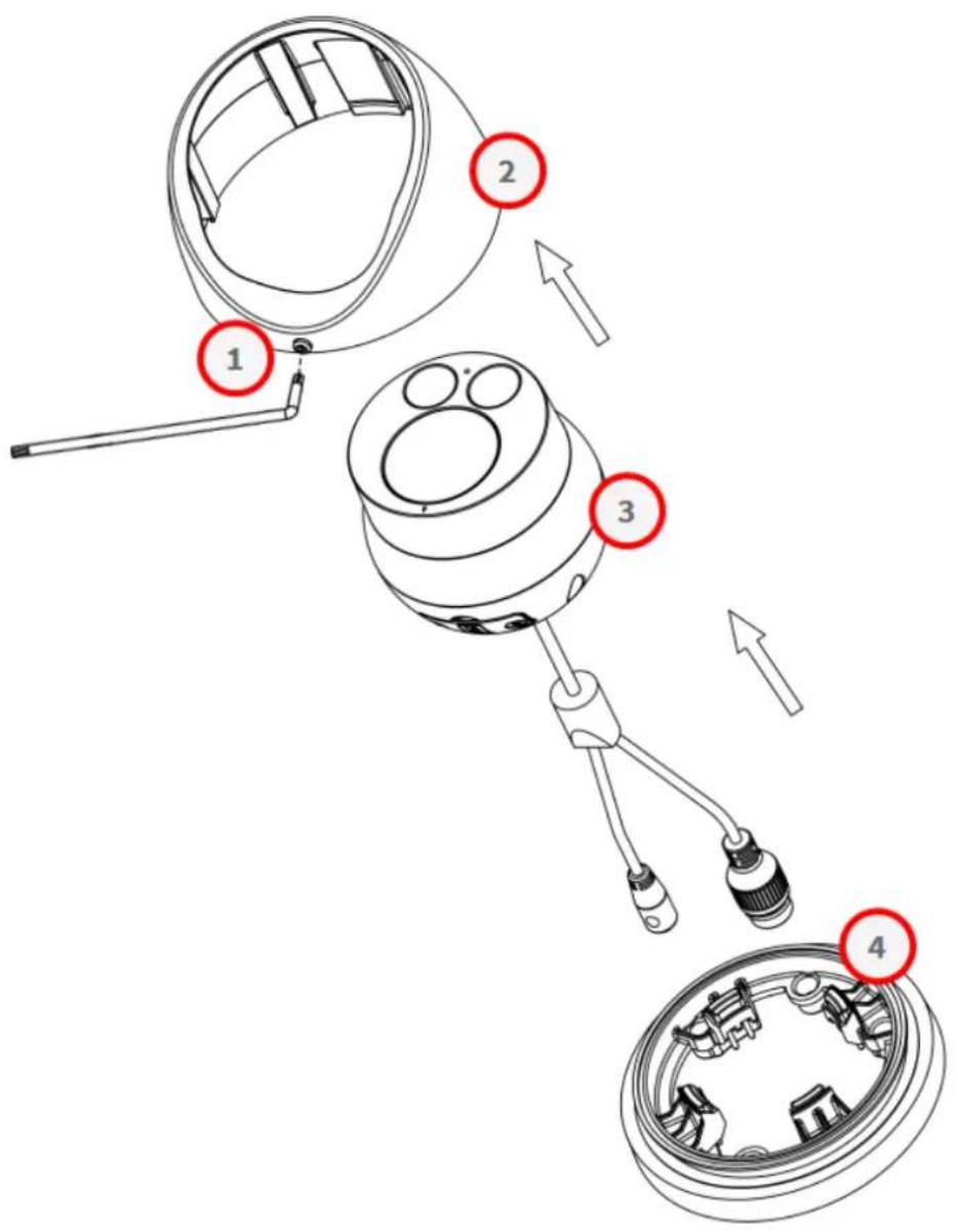
Inserting the SD Card
CAUTION! Always power down the camera before performing the following steps!
-
Remove the SD card cover ① from the camera lens module by loosening the screws ① with the T10 Torx wrench.
-
Insert the SD card into the corresponding slot.
-
Reattach the SD card cover.

NOTE!
It is not recommended to record with the microSD card for 24/7 continuously, as it may not be able to support long term continuous data read/write. Contact the manufacturer of the microSD card for information regarding the reliability and the life expectancy.
Mounting the Camera

natural_image
Technical line drawing of a mechanical device with a base and top component, showing internal components and directional arrows (no text or symbols)Mounting the camera routing the ethernet cable through the Surface

natural_image
Technical line drawing of a mechanical bearing assembly with internal components and a circular component (no text or symbols)Mounting the camera routing the ethernet cable on the surface
- Attach the drilling template to the wall or ceiling.
NOTE! You can choose to drill two or three holes on the mounting template. The following instructions are based on three holes.

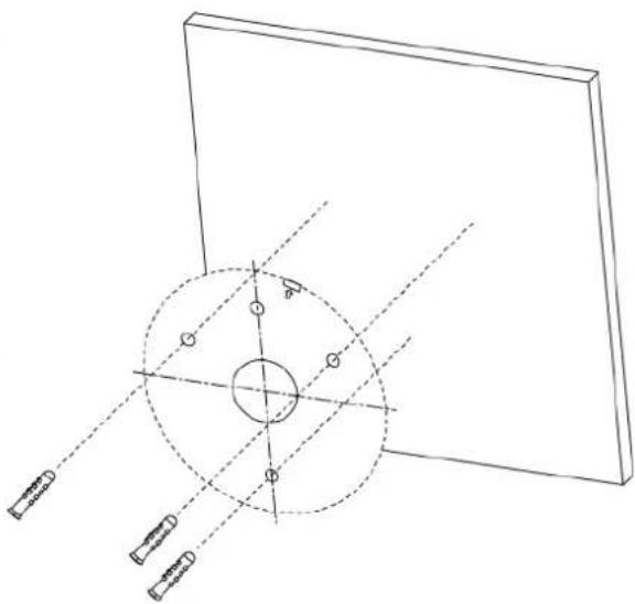
natural_image
Technical line drawing of a mechanical assembly with a circular component and four labeled components (no text or symbols)- Drill the three holes according to the drilling template and insert the plastic dowels supplied.
- If applicable, drill a hole for the cable gland.
- Only when routing the ethernet cable through the surface attach the cable entry cover.
- Use the self-tapping screws ① to attach the camera bottom case to the mounting surface ② prepared with the wall plugs.

- Attach the waterproof cover ③ to the ethernet cable.

- Connect the ethernet cable with the RJ-45 port of the camera and firmly close the waterproof cover.
NOTE!
■ The length of the Ethernet cable should not exceed 100 m/300 ft.
In some cases, an Ethernet crossover cable may be needed when connecting the camera directly to the PC.
- Align the groove on the top cover ④ with the rim one the camera bottom case and attach the camera lens module and top cover to the camera bottom case.

NOTE! Make sure the triangle arrow ⑤ is facing upwards

- Adjust the camera lens module to the desired field of view.

natural_image
Diagram of concentric circular layers with directional arrows indicating rotation (no text or symbols)[0° to 360°]

natural_image
Simple line drawing of a mechanical component with curved arrows indicating rotation (no text or symbols)[0° to 75°]

natural_image
Diagram of a surveillance camera with three lenses and directional arrows indicating rotation (no text or symbols)[0° to 360°]
- Close the housing screw ⑥ with the T10 Torx key to securely fasten the top cover to the lower camera housing.
Client System Requirements
System Hardware
CPU i5-2430M CPU@ 2.40GHZ
RAM 6 GB or above
Display NVIDIA GeForce 6 Series or ATI Mobility Radeon 9500
Power Supply PoE (IEEE 802.3af Class 3)
Network 10/100BASE-T Ethernet (RJ-45 connector)
System Software
Operating System Microsoft Windows 10 or above, MacOS Sierra or above
Browser Mozilla Firefox, Google Chrome, Apple Safari, Microsoft Edge
Accessing the Camera
The IP address of the camera can be found on the label on the camera housing.
-
Access the IP address of the camera with a web browser.
-
If you are accessing the camera's web interface for the first time, you must change the administrator password for user "ADMIN".
This Camera is Not Secure
Please setup the password for this device.
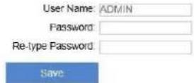
NOTE!
The password must include at least
■ 8 characters including
■ 1 uppercase letter
■ 1 special character
Further information about using the camera can be found in the "User Manual."
Further Reading
Manuals and Quick Installation documents
Technical Specifications
MOBOTIX MOVE Installation Hints
MOBOTIX Community




MOBOTIX
BeyondHumanVision
Brand : Mobotix
Model : Move Mx-VT1A-2-IR
Category : Security Camera