Match UP 1FX - Receiver Audiotec Fischer - Free user manual and instructions
Find the device manual for free Match UP 1FX Audiotec Fischer in PDF.


| Product Type | 1-Channel Upgrade Subwoofer Amplifier |
| Amplifier Technology | Class D |
| RMS Power @ 4 Ohm | 350 Watts |
| RMS Power @ 2 Ohm | 600 Watts |
| RMS Power @ 1 Ohm | 900 Watts |
| Max Power | Up to 1000 Watts RMS @ 1 Ohm |
| Audio Inputs | 1x RCA/Cinch, 2x Highlevel Speaker Input, 1x Remote In, 1x Remote Control Input |
| Speaker Output | 1x Speaker Output |
| Input Sensitivity (RCA) | 0.5 - 3 Volts or 1 - 6 Volts (switchable) |
| Input Sensitivity (Highlevel) | 3 - 16 Volts or 6 - 32 Volts (switchable) |
| Frequency Response | 10 Hz - 25,000 Hz |
| Lowpass Filter | 50 - 250 Hz adjustable (can be turned off) |
| Subsonic Filter | 15 Hz (can be turned off) |
| Signal-to-Noise Ratio | 108 dB |
| Total Harmonic Distortion | 0.002% |
| Damping Factor | 160 |
| Operating Voltage | 10.5 - 18 Volts (min. 6 Volts for 5 sec) |
| Fuse Rating | 2 x 30 A LP-Mini-fuse (APS) |
| Dimensions (H x W x D) | 46 x 130 x 153 mm / 1.81 x 5.12 x 6.02 in |
| Additional Features | DirectDSP, ADEP.3, Start-Stop Capability, Auto Turn-On via Highlevel Input |
Frequently Asked Questions - Match UP 1FX Audiotec Fischer
User questions about Match UP 1FX Audiotec Fischer
0 question about this device. Answer the ones you know or ask your own.
Ask a new question about this device
Download the instructions for your Receiver in PDF format for free! Find your manual Match UP 1FX - Audiotec Fischer and take your electronic device back in hand. On this page are published all the documents necessary for the use of your device. Match UP 1FX by Audiotec Fischer.
USER MANUAL Match UP 1FX Audiotec Fischer
1-channel upgrade subwoofer amplifier with integrated crossover and 1 Ohm stability
Low Voltage Range Konfiguration:
Highlevel: 3 - 16 Volt
Cinch: 0,5 - 3 Volt
High Voltage Range Konfiguration:
Highlevel: 6 - 32 Volt
Cinch: 1 - 6 Volt
- @ 4 Ohm....1 x 350 Watt
- @ 2 Ohm....1 x 600 Watt
- @ 1 Ohm....1 x 900 Watt*
Max. Leistung......Bis zu 1.000 Watt RMS @ 1 Ohm
Verstärkertechnologie......Class D
Eingänge 1 x Cinch
Congratulations on your purchase of this innovative and high-qual ity MATCH product.
We wish you many hours of enjoyment with your new MATCH UP 1FX.
Thanks to more than 30 years of experience in research and development of audio products this amplifier sets new standards in the range of amplifiers.
Yours, AUDIOTEC FISCHER
General instructions
General installation instructions for MATCH components
To prevent damage to the unit and possible injury, read this manual carefully and follow all installation instructions. This product has been checked for proper function prior to shipping and is guaranteed against manufacturing defects.
Before starting your installation, disconnect the battery's negative terminal to prevent damage to the unit, fire and / or risk of injury. For a proper performance and to ensure full warranty coverage, we strongly recommend to get this product installed by an authorized MATCH dealer.
Install your UP 1FX in a dry location with sufficient air circulation for proper cooling of the equipment.
For safety reasons, the UP 1FX must be professionally installed. Therefore, use the two mounting plates which are included in delivery. These are attached to the bottom of the amplifier with two short screws which are included in delivery, too.
When screwing the amplifier to the vehicle chassis, carefully examine the area around and behind the proposed installation location to ensure that there are no electrical cables or components, hydraulic brake lines or any part of the fuel tank located behind the mounting surface. Failure to do so may result in unpredictable damage to these components and possible costly repairs to the vehicle.
General instruction for connecting the UP 1FX amplifier
The UP 1FX amplifier may only be installed in motor vehicles which have a 12 Volts negative terminal connected to the chassis ground. Any other system could cause damage to the amplifier and the electrical system of the vehicle.
The positive cable from the battery for the entire sound system should be provided with a main fuse at a distance of max. 30 cm from the battery. The value of the fuse is calculated from the maximum total current draw of the car audio system.
Use only suitable cables with sufficient cable cross-section for the connection of the UP 1FX. The fuses of the amplifier may only be replaced by identically rated fuses (2 x 30 A) to avoid damage of the amplifier.
Prior to installation, plan the wire routing to avoid any possible damage to the wire harness. All cabling should be protected against possible crushing or pinching hazards. Also avoid routing cables close to potential noise sources such as electric motors, high power accessories and other vehicle harnesses.
Connectors and control units
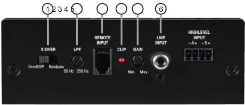
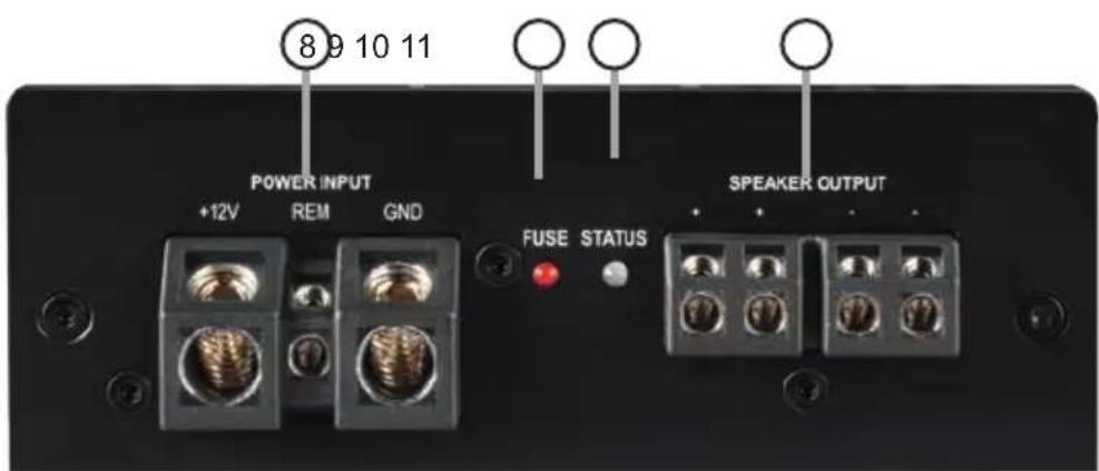
① Filter mode switch
Page 14, point 4
② Lowpass filter control (LPF)
Page 16, point 1
③ Remote control input
Page 16, point 2
④ Clipping LED
Page 16, point 3
⑤ Gain control
Page 15, point 6
⑥ Lowlevel line input
Page 14, point 2
⑦ Highlevel speaker input
Page 14, point 3
⑧ Power & remote connector
Page 14, point 5
⑨ Control LED for internal fuses
Page 16, point 4
⑩ Status LED
Page 16, point 5
⑪ Speaker output
Page 15, point 7
Configure the MATCH UP 1FX as follows
Caution: Carrying out the following steps will require special tools and technical knowledge. In order to avoid connection mistakes and / or damage, ask your dealer for assistance if you have any questions and follow all instructions in this manual (see page 11). It is recommended that this unit will be installed by an authorized MATCH dealer.
1. Adjusting input voltage range
Before proceeding to adjust the input voltage range, please take note of the following guidelines. This adjustment is only necessary when connecting devices from the following categories:
- Aftermarket radios with an output voltage exceeding 3 V RMS
- Premium sound system amplifiers with an output power of more than 50 W RMS
- Stand-alone DSPs with an output voltage exceeding 3 V RMS
For standard applications, such as connecting:
- Audiotec Fischer DSP amplifiers using RCA cables
- Factory radios
- Aftermarket radios with an output voltage of less than 3 V RMS
this adjustment is not required. In such cases, you can proceed directly to page 14, point 2.
To set the input voltage range, follow these steps:
a. Open the amplifier
Remove the side panel with the remote control input by loosening the three Allen screws and sliding out the bottom panel to the side.
b. Determine the output voltage of the signal source
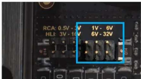
We recommend measuring the maximum output voltage using an appropriate measuring device or contacting your authorized MATCH dealer. If you are unsure, we recommend setting the jumper to the „High Voltage Range“ (Cinch 1 - 6 V / Highlevel 5 - 32 V) to
avoid potential damage to the device. To do this, the jumper must be moved to the factory-unused multi-pin connector, as shown in figure 2.
c. Place the jumper in the corresponding voltage range
To change the position of the jumper, simply lift it upwards and insert it into the desired position. Ensure that the jumper is fully inserted and not offset.
Overview of jumper positions:
Low voltage range configuration ( by default / see fig. 1):
Value range: HLI (Highlevel) 3 - 16 Volts RCA /Cinch 0.5 - 3 Volts
High voltage range configuration (see fig.2):
Value range: HLI (Highlevel) 6 - 32 Volts RCA / Cinch 1 - 6 Volts
Figure 1:
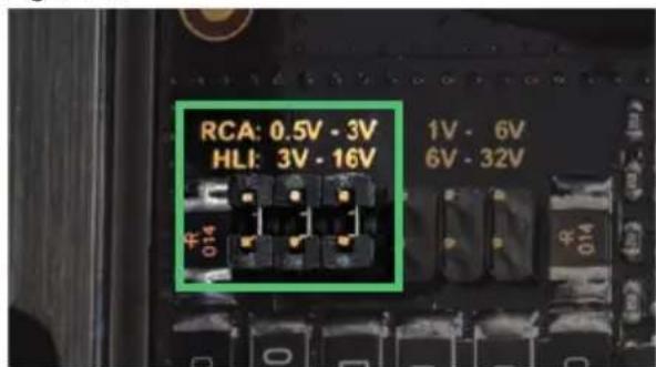
Figure 2:
d. Reassemble the amplifier
2. Connecting the pre-amplifier input
The lowlevel line input can be connected to signal sources such as head units, radios, DSPs and DSP amplifiers using appropriate cables. The input sensitivity can be optimally adapted to the signal source using the gain control (see page 15, point 6).
Important: It is strictly forbidden to use the Highlevel and lowlevel Line Input at the same time as this may cause severe damage to the signal source.
3. Connecting the highlevel speaker inputs
The highlevel loudspeaker inputs A and B can be connected directly to the loudspeaker outputs of the signal source (e.g., head units, radios, DSPs, DSP amplifiers) using appropriate cables (loudspeaker cables with 1 mm^2 / AWG 18 max. ).
The Highlevel Input is equipped with our proprietary ADEP.3 circuit (Advanced Diagnostics Error Protection 3rd generation) which ensures that the car radio detects the amplifier as a speaker and thus neither any function of the radio (e.g. fader) will be deactivated nor any error log in the CPU of the car will be created. If this input is used, the remote input (REM) does not need to be connected, as the amplifier will automatically turn on once a loudspeaker signal is applied.
Attention: Solely use the pluggable screw-terminal for the highlevel connector included in the delivery!
Important: It is strictly forbidden to use the Highlevel and lowlevel Line Input at the same time as this may cause severe damage to the signal source.
4. Adjusting the filter mode of the internal crossover
The UP 1FX is equipped with a DirectDSP function, which allows you to bypass the internal crossover. You can activate or deactivate this function using the X-Over switch (see page 12, point 1).
DirectDSP: In this mode, the internal crossover is deactivated, and the input signal is passed unfiltered to the output stages of the amplifier.
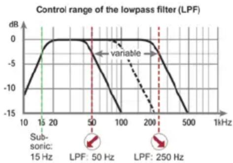
Bandpass: When the switch is set to this position, the internal crossover is active, and a 15 Hz highpass filter (Subsonic) is always active. This means a bandpass is created. By using the lowpass filter control (LPF, page 12, point 2) the bandpass can be adjusted between 50 Hz and 250 Hz.
line
| Frequency | Value | | --------- | ----- | | 15 Hz | -10 | | 50 Hz | 0 | | 250 Hz | -15 |5. Connection to power supply & remote Make sure to disconnect the battery before installing the MATCH UP 1FX!
Ensure correct polarity.
+12 V: Connector for the positive cable.
Connect the +12 V power cable to the positive terminal of the battery. The positive wire from the battery to the amplifiers power terminal needs to have an inline fuse at a distance of no more than 12 inches (30 cm) from the battery. The value of the fuse is calculated from the maximum total current input of the whole car audio system (UP 1FX = max. 60 A RMS at 12 V RMS power supply). If your power wires are short (less than 1 m / 40") then a wire gauge of 16 mm² / AWG 6 will be sufficient. In all other cases we strongly recommend gauges of 25 - 35 mm² / AWG 4 - 2!
GND: Connector for the ground cable. The ground wire should be connected to a common ground reference point (this is located where the negative terminal of the battery is grounded to the metal body of the vehicle) or to a prepared metal location on the vehicle chassis, i.e., an area cleaned of all paint residues. The cable should have the same gauge as the +12 V wire. Inadequate grounding causes audible interference and malfunctions.
REM: The remote input is used to switch on and off the UP 1FX. It is mandatory to connect this in put to the remote output of the preconnected device that provides the input signal to the UP 1FX.
This input does not need to be assigned if the highlevel input is used.
We do not recommend controlling the remote input via the ignition switch to avoid pop noise during turn on / off.
6. Adjustment of the input sensitivity
ATTENTION: It is mandatory to properly adapt the input sensitivity of the UP 1FX to the signal source to achieve the best possible signal quality and avoid damage to the amplifier. It is also mandatory to adjust the "Voltage Range" to the output voltage of your signal source (see page 13, point 1).
The input sensitivity can be optimally adapted to the signal source using the gain control (page 12, point 5).
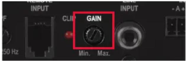
This is not a volume control; it's only for adjusting the amplifier gain. The setting of the control affects both the Highlevel and lowlevel Line Input.
Input sensitivity is factory set to 16 Volts (high-level) and 3 Volts (RCA / Cinch). This is definitely the best setting in most applications.
The Gain control ranges are:
Low Voltage Range configuration:
Highlevel: 3 - 16 Volts
RCA / Cinch: 0.5 - 3 Volts
High Voltage Range configuration:
Highlevel: 6 - 32 Volts
RCA / Cinch: 1 - 6 Volts
If the signal source provides a lower output voltage, the input sensitivity can be smoothly increased via the Gain Control.
If your signal source delivers a higher output voltage – for example, if a factory-installed amplifier serves as a signal source – the input sensitivity must be lowered via the control, and
the correct configuration of the "Voltage Range" jumper must be checked.
If you are not sure regarding the signal source's output voltage, please contact your MATCH specialist dealer.
The Clipping LED (see page 12, point 4) serves as monitoring tool.
Note: Don't connect any loudspeakers to the outputs of the amplifier during this setup.
For adjustment please proceed as follows:
-
Turn on the amplifier.
-
Adjust the volume of your radio to approx. 90 % of the max. volume and playback an appropriate test tone, e.g., pink noise (0 dB).
-
If the Clipping LED already lights up, you have to reduce the input sensitivity via the Gain Control until the LED turns off.
-
Increase the input sensitivity by turning the Gain Control clockwise until the Clipping LED lights up. Now turn the control counterclockwise until the Clipping LED turns off again.
7. Connecting the loudspeaker outputs
The loudspeaker outputs can be connected directly to the wires of the loudspeakers. Never connect any of the loudspeaker cables with the chassis ground as this will damage your amplifier and your speakers. Ensure that the loudspeakers are correctly connected (in phase), i.e., plus to plus and minus to minus.
Exchanging plus and minus causes a total loss of bass reproduction. The plus pole is indicated on most speakers. The impedance must not be lower than 1 Ohm, otherwise, the amplifier protection will be activated. Examples for speaker configurations can be found on page 17 et sqq.
8. Filter settings
When using the DirectDSP function (see page 14, point 4), adjust crossover frequencies in the preconnected DSP or DSP amplifier. For bandpass function, use the lowpass filter control (LPF) on the device. In this case, a 15 Hz high-pass filter (subsonic) is always active.
1. Lowpass filter control (LPF)
This control allows you to adjust the lowpass filter of the bandpass between 50 Hz and 250 Hz. The control is activated when the X-Over switch is set to "Bandpass" (see page 14, point 4).
2. Remote control input
This input is used for connecting an optionally available remote control. The remote control can be used to adjust the volume of the subwoofer.
3. Clipping LED
Normally, the Clipping LED is off and only lights up if the lowlevel Line Input or one of the High-level Inputs is overdriven.
On (red): One of the analog signal inputs is overdriven. Reduce the input sensitivity using the Gain Control until the LED goes out. Instructions on how to reduce the input sensitivity are described on page 15, point 6.
4. Fuse LED
The LED indicates the status of the internal fuses.
Off: Fuses are intact.
On (red): The internal fuses are blown. They may only be replaced by identically rated fuses (2 x 30 A) to avoid damage of the amplifier.
Using higher-rated fuses can lead to dangerous consequential damage!
5. Status LED
The Status LED indicates the operating mode of the amplifier.
Green: The amplifier is ready for operation.
Orange: There is a short circuit at the speaker output or a faulty connection. In this case, check all connections for errors.
Red: Protection Mode active. A malfunction has occurred that may have different root causes. The amplifier is equipped with protection circuits against over- and undervoltage as well as overheating. Please check for connecting failures such as short-circuits or other incorrect connections. If the amplifier is overheated, the internal temperature protection will turn off the signal output until it reaches a safe temperature level again. If the amplifier does not turn on, it is defective and needs to be sent to your local authorized dealer for repair service.
Note: If you have activated the DirectDSP function, the crossover frequencies for the subsonic or lowpass must be set in the preconnected DSP / DSP amplifier.
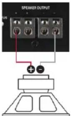
Mono subwoofer application
Subwoofer with one voice coil (single voice coil)
RMS output power ≤ 1% THD+N:
1 x 4 Ohms: 350 Watts
1 x 2 Ohms: 600 Watts
1 x 1 Ohm: 900 Watts
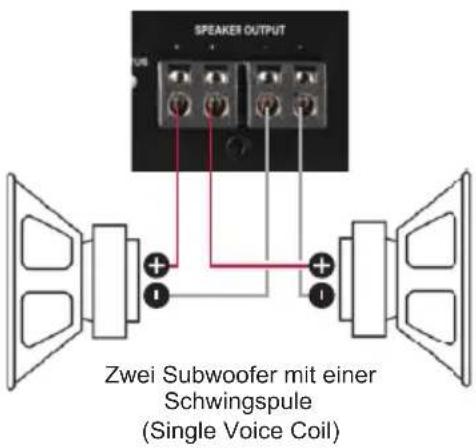
Two subwoofers with one voice coil (single voice coil) or one subwoofer with dual voice coil are connected in parallel.
Note: The parallel connection of two voice coils will result in halving the impedance!
RMS output power ≤ 1% THD+N:
Two subwoofers with 1 x 4 Ohms correspond to a total impedance of 2 Ohms: 600 Watts
One subwoofer with 2 x 4 Ohms also corresponds to a total impedance of 2 Ohms: 600 Watts
Two subwoofers with 1 x 2 Ohms correspond to a total impedance of 1 Ohm: 900 Watts
One subwoofer with 2 x 2 Ohms also corresponds to a total impedance of 1 Ohm: 900 Watts
Note: The parallel connection of 1 Ohm voice coils will result in shutdown of the amplifier.
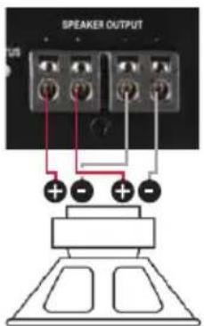
Two subwoofers with one voice coil (single voice coil) or one subwoofer with dual voice coil are connected in series.
Note: The connection of two voice coils in series will result in doubling the impedance!
RMS output power ≤ 1% THD+N;
Two subwoofers with 1 x 2 Ohms correspond to a total impedance of 4 Ohms: 350 Watts
One Subwoofer with 2 x 2 Ohms also corresponds to a total impedance of 4 Ohms: 350 Watts
Two subwoofers with 1 x 1 Ohm correspond to a total impedance of 2 Ohms: 600 Watts
One subwoofer with 2 x 1 Ohm also correspond to a total impedance of 2 Ohms: 600 Watts
Note: The negative terminal of the first voice coil has to be connected to the positive terminal of the second voice coil by using a speaker wire with the same gauge as the other speaker.
Output power RMS ( ≤ 1% THD+N)
- @ 4 Ohms....1 x 350 Watts
- @ 2 Ohms....1 x 600 Watts
- @ 1 Ohms....1 x 900 Watts*
Max. output power.....Up to 1,000 Watts RMS @ 1 Ohm
Amplifier technology ....Class D
Inputs....1 x RCA / Cinch
2 x Highlevel speaker input
1 x Remote In
1 x Remote control input
Input sensitivity....RCA / Cinch: 0.5 - 3 Volts or 1 - 6 Volts
Highlevel: 3 - 16 Volts or 6 - 32 Volts
Input impedance....RCA / Cinch: 8.6 kOhms
Highlevel: 9 - 33 Ohms
Outputs....1 x Speaker output
Frequency response....10 Hz - 25,000 Hz
Lowpass 50 - 250 Hz adjustable (can be turned off)
Subsonic....15 Hz (can be turned off)
Slope ....Lowpass: 12 dB
Subsonic: 12 dB
Signal-to-noise ratio....108 dB
Distortion (THD)....0.002 %
Damping factor....160
Operating voltage 10.5 - 18 Volts (max. 5 sec. down to 6 Volts)
Idle current....1050 mA
Fuse....2 x 30 A LP-Mini-fuse (APS)
Power rating ....DC 12 V=80 A max.
Ambient operating temperature range....-40 °C to +70 °C
Additional features....Active, adjustable crossover, Start-Stop capability, highlevel input with automatic turn on function, ADEP.3, DirectDSP function
Dimensions (H x W x D)....46 x 130 x 153 mm / 1.81 x 5.12 x 6.02"
* Continuous 1 Ohm power achieved only with music signal
Warranty Disclaimer
The warranty service is based on the statutory regulations. Defects and damage caused by overload or improper handling are excluded from the warranty service. Any return can only take place following prior consultation, in the original packaging together with a detailed description of the error and a valid proof of purchase.
Technical modifications, misprints and errors excepted! We accept no liability for damage to the vehicle or device defects caused by the incorrect operation of the device. This product has been issued a CE marking. This means that the device is certified for use in vehicles within the European Union (EU).
AUDIOTEC
FISCHER
- General instructions
- General installation instructions for MATCH components
- General instruction for connecting the UP 1FX amplifier
- Connectors and control units
- Configure the MATCH UP 1FX as follows
- Adjusting input voltage range
- To set the input voltage range, follow these steps:
- a. Open the amplifier
- b. Determine the output voltage of the signal source
- c. Place the jumper in the corresponding voltage range
- Overview of jumper positions:
- Connecting the pre-amplifier input
- Connecting the highlevel speaker inputs
- Adjusting the filter mode of the internal crossover
- Connection to power supply & remote Make sure to disconnect the battery before installing the MATCH UP 1FX!
- Adjustment of the input sensitivity
- The Gain control ranges are:
- Connecting the loudspeaker outputs
- Filter settings
- Lowpass filter control (LPF)
- Remote control input
- Clipping LED
- Fuse LED
- Status LED
- Mono subwoofer application
- RMS output power ≤ 1% THD+N;
- Warranty Disclaimer
Brand : Audiotec Fischer
Model : Match UP 1FX
Category : Receiver