
B150GT5 - Uncategorized BIOSTAR - Free user manual and instructions
Find the device manual for free B150GT5 BIOSTAR in PDF.


| Product Type | Motherboard |
| Form Factor | ATX |
| Dimensions | 305 mm x 225 mm |
| CPU Socket | LGA1151 |
| Chipset | Intel B150 |
| Memory Support | 4x DDR4 DIMM, dual channel, up to 64 GB, 2133/1866 MHz |
| Storage Interfaces | 1x SATA Express, 6x SATA III (6 Gb/s), supports AHCI |
| LAN | 1x Intel I219V, 10/100/1000 Mbps |
| Audio | ALC892, 7.1 channels, High Definition Audio |
| USB Ports | 6x USB 3.0 (4 rear, 2 via header), 6x USB 2.0 (2 rear, 4 via header) |
| Expansion Slots | 1x PCIe 3.0 x16 (x16), 1x PCIe 3.0 x16 (x4), 1x PCIe 3.0 x1, 3x PCI |
| Rear I/O | 1x PS/2, 1x DVI-D, 1x VGA, 1x HDMI, 1x LAN, 2x USB 2.0, 4x USB 3.0, 6x audio jacks |
| Internal I/O | 1x 24-pin ATX, 1x 8-pin ATX 12V, 1x CPU fan, 2x system fan, front panel, audio, USB 2.0/3.0 headers, COM port, S/PDIF out, clear CMOS |
| Power Supply | ATX 24-pin and 8-pin connectors, recommended PSU > 450W |
| Operating System Support | Windows 7, 8.1 (64-bit), 10 (64-bit) |
| Cooling | 1x CPU fan header (4-pin), 2x system fan headers (4-pin) |
| Special Features | Dual BIOS switch, LN2 mode jumper, RGB LED strip header (5050), ECO/Sport mode touch buttons, RACING GT software |
| Package Contents | 4x SATA cables, rear I/O panel, user manual, driver DVD, optional LED strip |
Frequently Asked Questions - B150GT5 BIOSTAR
User questions about B150GT5 BIOSTAR
0 question about this device. Answer the ones you know or ask your own.
Ask a new question about this device
Download the instructions for your Uncategorized in PDF format for free! Find your manual B150GT5 - BIOSTAR and take your electronic device back in hand. On this page are published all the documents necessary for the use of your device. B150GT5 by BIOSTAR.
USER MANUAL B150GT5 BIOSTAR
FCC Information and Copyright
This equipment has been tested and found to comply with the limits of a Class B digital device, pursuant to Part 15 of the FCC Rules. These limits are designed to provide reasonable protection against harmful interference in a residential installation. This equipment generates, uses, and can radiate radio frequency energy and, if not installed and used in accordance with the instructions, may cause harmful interference to radio communications. There is no guarantee that interference will not occur in a particular installation.
The vendor makes no representations or warranties with respect to the contents here and specially disclaims any implied warranties of merchantability or fitness for any purpose. Further the vendor reserves the right to revise this publication and to make changes to the contents here without obligation to notify any party beforehand.
Duplication of this publication, in part or in whole, is not allowed without first obtaining the vendor's approval in writing.
The content of this user's manual is subject to be changed without notice and we will not be responsible for any mistakes found in this user's manual. All the brand and product names are trademarks of their respective companies.

Short Declaration of conformity We declare this product is complying with the laws in force and meeting all the essential requirements as specified by the directives 2004/108/CE, 2006/95/CE and 1999/05/CE whenever these laws may be applied
Table Of Contents
FCC Information and Copyright 1
Chapter 1: Introduction....3
1.1 Before You Start....3
1.2 Package Checklist....3
1.3 Specifications 4
1.4 Rear Panel Connectors....5
1.5 Motherboard Layout 6
Chapter 2: Hardware installation....7
2.1 Install Central Processing Unit (CPU) 7
2.2 Install a Heatsink....9
2.3 Connect Cooling Fans 10
2.4 Install System Memory 10
2.5 Expansion Slots 12
2.6 Jumper & Switch Setting.... 13
2.7 Headers & Connectors.... 14
2.8 Buttons & LEDs 18
Chapter 3: UEFI BIOS & Software....19
3.1 UEFI BIOS Setup.... 19
3.2 BIOS Update.... 19
3.3 Software....23
Chapter 4: Useful help....31
4.1 Driver Installation 31
4.2 AMI BIOS Beep Code 32
4.3 AMI BIOS post code 32
4.4 Troubleshooting.... 34
4.5 RAID Functions.... 35
APPENDIX I: Specifications in Other Languages 37
Arabic....37
German 38
Russian....39
Spanish 40
Thai 41
Chapter 1: Introduction
1.1 Before You Start
Thank you for choosing our product. Before you start installing the motherboard, please make sure you follow the instructions below:
• Prepare a dry and stable working environment with sufficient lighting.
• Always disconnect the computer from power outlet before operation.
- Before you take the motherboard out from anti-static bag, ground yourself properly by touching any safely grounded appliance, or use grounded wrist strap to remove the static charge.
- Avoid touching the components on motherboard or the rear side of the board unless necessary. Hold the board on the edge, do not try to bend or flex the board.
- Do not leave any unfastened small parts inside the case after installation. Loose parts will cause short circuits which may damage the equipment.
- Keep the computer from dangerous area, such as heat source, humid air and water.
- The operating temperatures of the computer should be 0 to 45 degrees Celsius.
• To avoid injury, be careful of:
Sharp pins on headers and connectors
Rough edges and sharp corners on the chassis
Damage to wires that could cause a short circuit
1.2 Package Checklist
- Serial ATA Cable x4
• Rear I/O Panel for ATX Case x1 - User's Manual x1
• Fully Setup Driver DVD x1
• LED Strip x1 (optional)
Note
» The package contents may be different due to the sales region or models in which it was sold. For more information about the standard package in your region, please contact your dealer or sales representative.
1.3 Specifications
| Specifications | |
| CPU Support | Socket 1151 for Intel® Core i7 / i5 / i3 / Pentium / Celeron processorMaximum CPU TDP (Thermal Design Power): 95Watt* Please refer to www.biostar.com.tw for CPU support list. |
| Chipset | INTEL® Z170 (Z170GT5)INTEL® B150 (B150GT5) |
| Memory | Supports Dual Channel DDR4 2133/1866Supports Dual Channel DDR4 3200(OC), only for Z170GT54x DDR4 DIMM Memory Slot, Max. Supports up to 64 GB MemoryEach DIMM supports non-ECC 4/8/16GB DDR4 module* Please refer to www.biostar.com.tw for Memory support list. |
| Storage | INTEL® Z170:1x SATA Express Connector (16Gb/s) / 2x SATA III Connector (6Gb/s)4x SATA III Connector (6Gb/s)supports RAID 0,1,10, 5 & AHCIINTEL® B150:1x SATA Express Connector (16Gb/s) / 2x SATA III Connector (6Gb/s)4x SATA III Connector (6Gb/s)supports AHCI |
| LAN | Intel i219V1x 10/ 100/ 1000 Mb/s auto negotiation, Half / Full duplex capability |
| Audio Codec | ALC8927.1 Channels, High Definition Audio, Hi-Fi(Front + Rear) |
| USB | 6x USB 3.0 port (4 on rear I/Os and 2 via internal header)6x USB 2.0 port (2 on rear I/Os and 4 via internal header) |
| Expansion Slots | 3x PCI Slot1x PCIe 3.0 x1 Slot1x PCIe 3.0 x16 Slot (x4)1x PCIe 3.0 x16 Slot (x16) |
| Rear I/Os | 1x PS/2 Keyboard/ Mouse1x DVI-D Port1x VGA Port1x HDMI Port1x LAN port2x USB 2.0 Port4x USB 3.0 Port6x Audio Jack |
| Internal I/Os | 1x SATA Express Connector / 2x SATA III Connector4x SATA III Connector2x USB 2.0 Header1x USB 3.0 Header1x 8-Pin Power Connector1x 24-Pin Power Connector1x CPU Fan Connector2x System Fan Connector1x Front Panel Header1x Front Audio Header1x Clear CMOS Header1x S/PDIF out Connector1x COM Port Header |
| Form Factor ATX Form Factor, 305 mm x 225 mm | |
| OS Support | Windows 7/ 8.1(64bit)/ 10(64bit)Biostar reserves the right to add or remove support for any OS with or without notice. |
1.4 Rear Panel Connectors
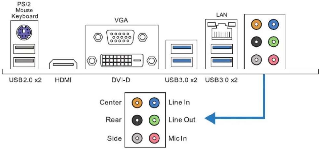
Note
» HDMI, DVI-D & VGA ports only work with an Intel® integrated Graphics Processor.
» Maximum resolution
HDMI: 4096 x 2160 @24Hz, compliant with HDMI 1.4a
VGA: 1920 x 1200 @60Hz
DVI-D: 1920 x 1200 @60Hz
» The mainboard supports three onboard display outputs at same time and the display output configuration can be selected in Intel graphics driver utility.
1.5 Motherboard Layout
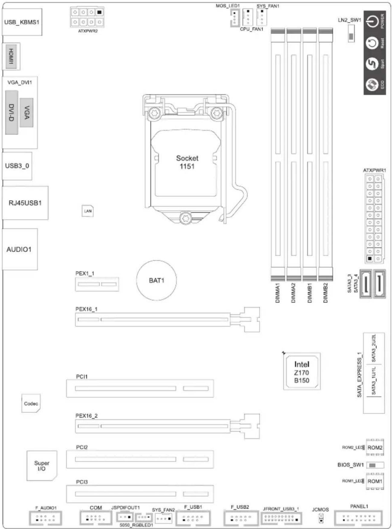
Note
» ■ represents the 1st pin.
Chapter 2: Hardware installation
2.1 Install Central Processing Unit (CPU)
Step 1: Locate the CPU socket on the motherboard
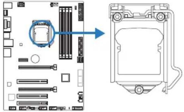
Note
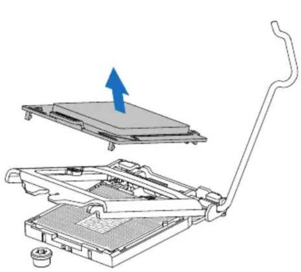
» Remove pin cap before installation, and make good preservation for future use. When the CPU is removed, cover the pin cap on the empty socket to ensure pin legs won't be damaged.
» The motherboard might equip with two different types of pin cap. Please refer below instruction to remove the pin cap.
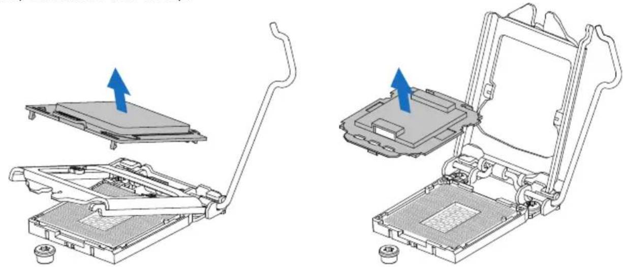
Step 2: Pull the socket locking lever out from the socket and then raise the lever up.
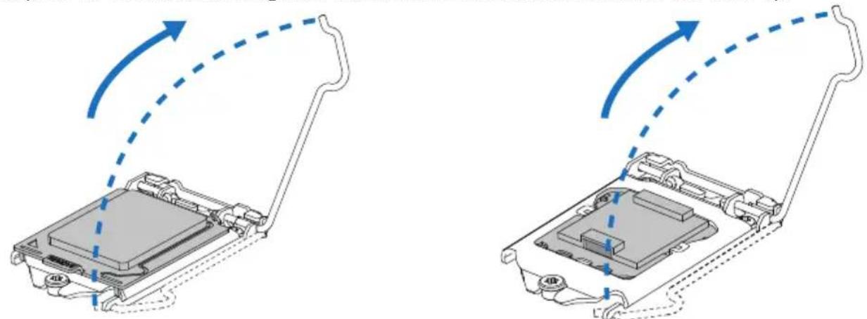
natural_image
Diagram showing two views of a device with arrows indicating motion, no text or symbols presentStep 3: Remove the Pin Cap.
natural_image
Technical illustration of a computer chassis with two views showing internal components and blue arrows indicating assembly direction (no text or symbols present)Step 4: Hold processor with your thumb and index fingers, oriented as shown. Align the notches with the socket. Lower the processor straight down without tilting or sliding the processor in the socket.

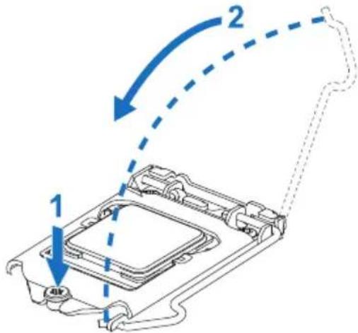
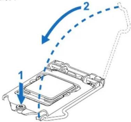
Step 5: Hold the CPU down firmly, and then lower the lever to locked position to complete the installation.
Note
» Ensure that you install the correct CPU designed for LGA1151 socket.
» The CPU fits only in one correct orientation. Do not force the CPU into the socket to prevent damaging the CPU.
2.2 Install a Heatsink
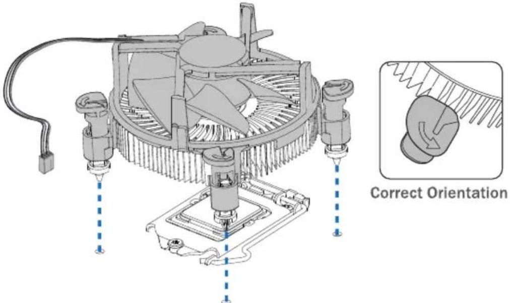
Step 1: Place the CPU fan assembly on top of the installed CPU and make sure that the four fasteners match the motherboard holes. Orient the assembly and make the fan cable is closest to the CPU fan connector.
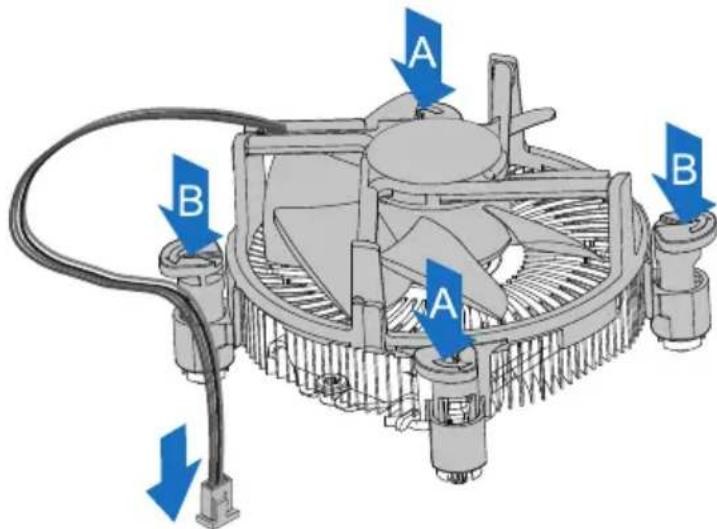
Step 2: Press down two fasteners at one time in a diagonal sequence to secure the CPU fan assembly in place. As each fastener locks into position a click should be heard.
Note
» Apply the thermal interface material on the CPU before heatsink installation, if necessary.
» Do not forget to connect the CPU fan connector.
» For proper installation, please kindly refer to the installation manual of your CPU heatsink.
2.3 Connect Cooling Fans
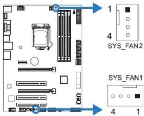
These fan headers support cooling-fans built in the computer. The fan cable and connector may be different according to the fan manufacturer.
CPU_FAN1: CPU Fan Header
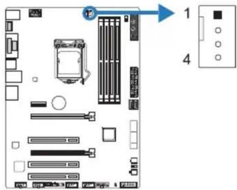
| Pin Assignment |
| 1 Ground |
| 2 +12V |
| 3 FAN RPM rate sense |
| 4 Smart Fan Control (By Fan) |
SYS_FAN1/2: System Fan Header
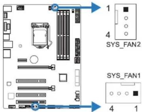
| Pin Assignment |
| 1 Ground |
| 2 +12V |
| 3 FAN RPM rate sense |
| 4 Smart Fan Control (By Fan) |
Note
» CPU_FAN1, SYS_FAN1/2 support 4-pin and 3-pin head connectors. When connecting with wires onto connectors, please note that the red wire is the positive and should be connected to pin#2, and the black wire is Ground and should be connected to pin#1(GND).
2.4 Install System Memory
DDR4 Modules
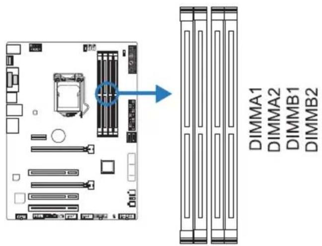
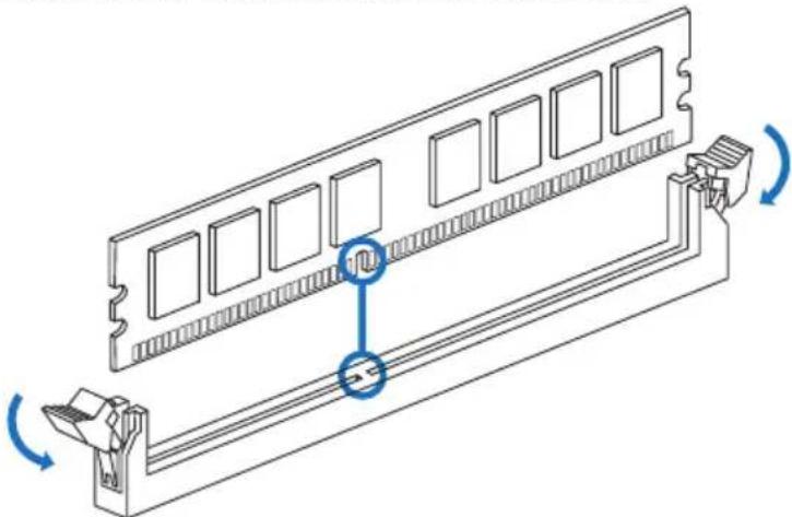
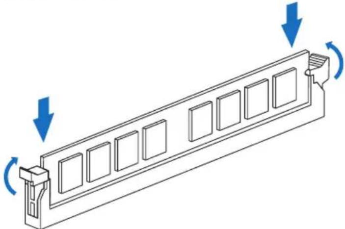
Step 1: Unlock a DIMM slot by pressing the retaining clips outward. Align a DIMM on the slot such that the notch on the DIMM matches the break on the slot.
natural_image
Technical line drawing of a computer RAM module with mounting bracket and scroll wheel (no text or symbols)Step 2: Insert the DIMM vertically and firmly into the slot until the retaining clips snap back in place and the DIMM is properly seated.
natural_image
Technical line drawing of a mechanical component with directional arrows indicating motion (no text or symbols)Note
» If the DIMM does not go in smoothly, do not force it. Pull it all the way out and try again.
Memory Capacity
| DIMM Socket Location DDR4 Module Total Memory Size | |
| DIMMA1 4GB/8GB/16GB | Max is 64GB. |
| DIMMA2 4GB/8GB/16GB | |
| DIMMB1 4GB/8GB/16GB | |
| DIMMB2 4GB/8GB/16GB | |
Dual Channel Memory Installation
Please refer to the following requirements to activate Dual Channel function: Install memory module of the same density in pairs, shown in the table.
| Dual Channel Status DIMMA1 DIMMA2 DIMMB1 DIMMB2 | ||||
| Enabled O X O X | ||||
| Enabled X O X O | ||||
| Enabled O O O O | ||||
(O means memory installed, X means memory not installed.)
Note
» When installing more than one memory module, we recommend to use the same brand and capacity memory on this motherboard.
2.5 Expansion Slots
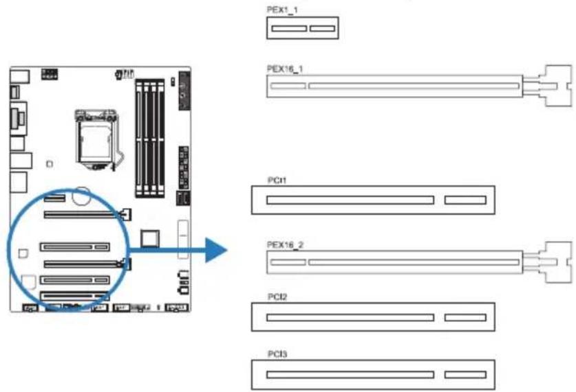
PCI1/PCI2/PCI3: Peripheral Component Interconnect Slots
The PCI slots support cards used in PCs include: LAN cards, sound cards, modems, TV • tuner cards and other cards that comply with PCI standard.
PEX16\_1: PCI-Express Gen3 x16 Slot (x16 speed)
• PCI-Express 3.0 compliant.
- Maximum theoretical realized bandwidth of 16GB/s simultaneously per direction, for an aggregate of 32GB/s totally.
PEX16\_2: PCI-Express Gen3 x16 Slot (x4 speed)
• PCI-Express 3.0 compliant.
• Data transfer bandwidth up to 4GB/s per direction; 8GB/s in total
PEX1\_1: PCI-Express Gen3 x1 Slot
PCI-Express 3.0 compliant.
Data transfer bandwidth up to 1GB/s per direction; 2GB/s in total
Install an Expansion Card
You can install your expansion card by following steps:
- Read the related expansion card's instruction document before install the expansion card into the computer.
- Remove your computer's chassis cover, screws and slot bracket from the computer.
- Place a card in the expansion slot and press down on the card until it is completely seated in the slot.
- Secure the card's metal bracket to the chassis back panel with a screw.
- Replace your computer's chassis cover.
• Power on the computer, if necessary, change BIOS settings for the expansion card.
• Install related driver for the expansion card.
2.6 Jumper & Switch Setting
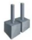
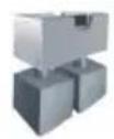
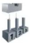
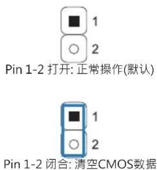
The illustration shows how to set up jumpers. When the jumper cap is placed on pins, the jumper is "close", if not, that means the jumper is "open".
Pin opened Pin closed Pin 1-2 closed
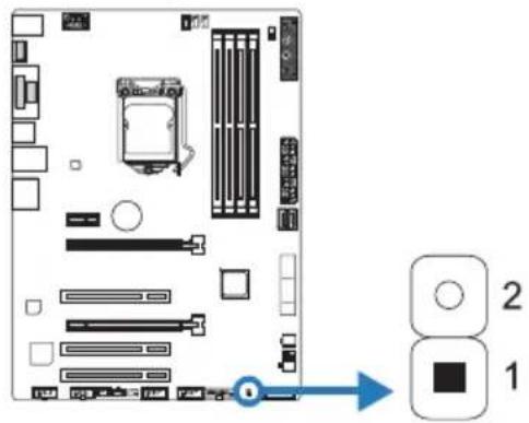
JCMOS1: Clear CMOS Jumper
The jumper allows users to restore the BIOS safe setting and the CMOS data. Please carefully follow the procedures to avoid damaging the motherboard.
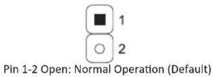
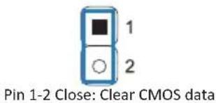
Clear CMOS Procedures:
- Remove AC power line.
- Set the jumper to "Pin 1-2 close", you can use a metal object like a screwdriver to touch the two pins.
- Wait for five seconds.
- After clearing the CMOS values, be sure the jumper is "Pin 1-2 open".
- Power on the AC.
- Load Optimal Defaults and save settings in CMOS.
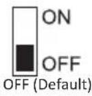
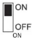
BIOS\_SW1: Dual BIOS Switch
The Dual BIOS Switch allows you to choose one of the BIOS ROMs (ROM1/ROM2) for boot up.
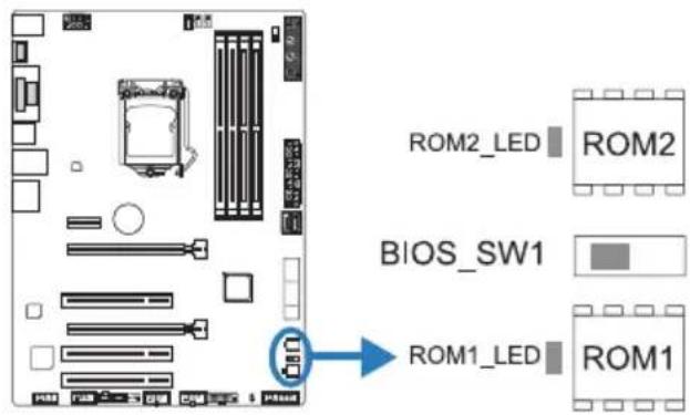
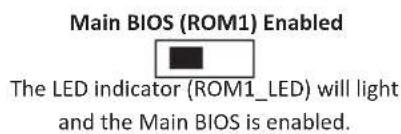
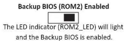
Note
» Do not use this switch when your system is power-on.
» Before flashing BIOS ROMs, please make sure this switch is set to the BIOS ROM which you want to update.
When the LN2 mode is ON, the CPU will run at its lowest frequency (e.g., 800MHz) to avoid unexpected system shutdown.
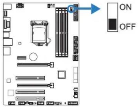
Note
» We are not responsible for the damages or risks caused by overclocking.
2.7 Headers & Connectors
ATXPWR1: ATX Power Source Connector
For better compatibility, we recommend to use a standard ATX 24-pin power supply for this connector. Make sure to find the correct orientation before plugging the connector.
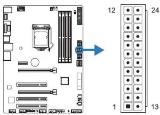
| Pin Assignment Pin Assignment | ||
| 13 +3.3V 1 +3.3V | ||
| 14 -12V 2 +3.3V | ||
| 15 Ground 3 Ground | ||
| 16 PS_ON 4 +5V | ||
| 17 Ground 5 Ground | ||
| 18 Ground 6 +5V | ||
| 19 Ground 7 Ground | ||
| 20 NC 8 PW_OK | ||
| 21 +5V 9 Standby Voltage+5V | ||
| 22 +5V 10 +12V | ||
| 23 +5V 11 +12V | ||
| 24 Ground 12 +3.3V | ||
ATXPWR2: ATX Power Source Connector
The connector provides +12V to the CPU power circuit. If the CPU power plug is 4-pin, please plug it into Pin 1-2-5-6 of ATXPWR2.
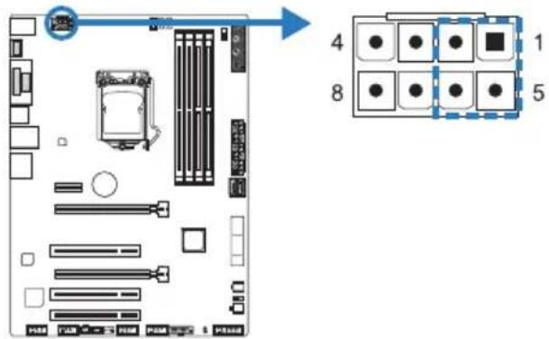
| Pin Assignment |
| 1 +12V |
| 2 +12V |
| 3 +12V |
| 4 +12V |
| 5 Ground |
| 6 Ground |
| 7 Ground |
| 8 Ground |
Note
» Before you power on the system, please make sure that both ATXPWR1 and ATXPWR2 connectors have been plugged-in.
» Insufficient power supplied to the system may result in instability or the peripherals not functioning properly. Use of a PSU with a higher power output is recommended when configuring a system with more power-consuming devices.
PANEL1: Front Panel Header
This 16-pin header includes Power-on, Reset, HDD LED, Power LED, and speaker connection.
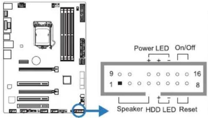
| Pin | Assignment Function Pin A | Assignment Function | |
| 1 +5V | Speaker Connector | 9 N/A | N/A |
| 2 N/A 10 N/A | |||
| 3 N/A 11 N/A N/A | |||
| 4 Speaker 12 Power LED (+) | Power LED | ||
| 5 HDD LED (+) | Hard drive LED 14 | 13 Power LED (+) | |
| 6 HDD LED (-) | 4 Power LED (-) | ||
| 7 Ground | Reset button 15 | 15 Power button | Power-on button |
| 8 Reset control | 6 Ground |
SATA\_Express\_1: SATA Express Connector
Each SATA Express connector can support one SATA Express device or two SATA devices.
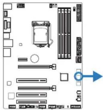
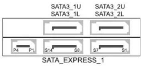
| Pin | Assignment | Pin Assignment | |
| S1/S8 G | round P1 | Reserved | |
| S2/S9 TX+ | P2 | PERST# | |
| S3/S10 | TX- | P3 | CLKREQ#/DEVSLP |
| S4/S11 | Ground | P4 | IFDet |
| S5/S12 | RX- | ||
| S6/S13 | RX+ | ||
| S7/S14 | Ground | ||
SATA3\_3/3\_4: Serial ATA Connectors
These connectors connect to SATA hard disk drives via SATA cables.
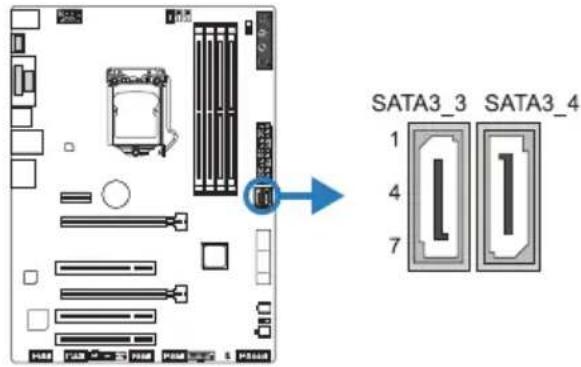
| Pin Assignment |
| 1 Ground |
| 2 TX+ |
| 3 TX- |
| 4 Ground |
| 5 RX- |
| 6 RX+ |
| 7 Ground |
JFRONT\_USB3\_1: Header for USB 3.0 Ports at Front Panel
This header allows user to add additional USB ports on the PC front panel, and also can be connected with a wide range of external peripherals.
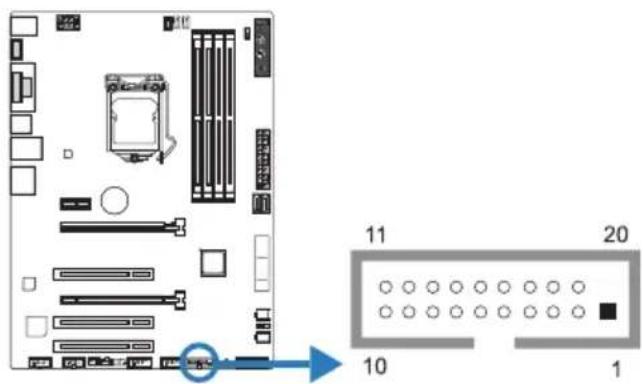
| Pin | Assignment Pin | Assignment |
| 1 | VBUS0 11 D2+ | |
| 2 | SSRX1- 12 D2- | |
| 3 | SSRX1+ 13 Ground | |
| 4 | Ground 14 SSTX2+ | |
| 5 | SSTX1- 15 SSTX2- | |
| 6 | SSTX1+ 16 Ground | |
| 7 | Ground 17 SSRX2+ | |
| 8 | D1- 18 SSRX2- | |
| 9 | D1+ 19 | VBUS1 |
| 10 | ID | 20 Key |
F\_USB1/2: Header for USB 2.0 Ports at Front Panel
This header allows user to add additional USB ports on the PC front panel, and also can be connected with a wide range of external peripherals.
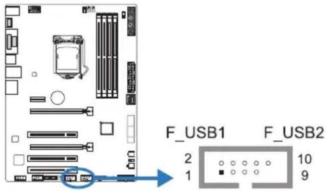
| Pin | Assignment |
| 1 +5V (fused) | |
| 2 +5V (fused) | |
| 3 USB- | |
| 4 USB- | |
| 5 USB+ | |
| 6 USB+ | |
| 7 Ground | |
| 8 Ground | |
| 9 Key | |
| 10 | NC |
JSPDIFOUT1: Digital Audio-out Connector
The connector is for connecting the S/PDIF output bracket.
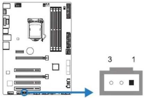
| Pin Assignment |
| 1 +5V |
| 2 SPDIF_OUT |
| 3 Ground |
F\_AUDIO1: Front Panel Audio Header
This header allows user to connect the chassis-mount front panel audio I/O which supports HD and AC'97 audio standards.
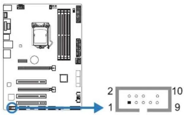
| HD Audio AC'97 | |||
| Pin | Assignment Pin | Assignment | |
| 1 Mic | Left in 1 Mic In | ||
| 2 Ground | 2 Ground | ||
| 3 Mic | Right in 3 Mic | Power | |
| 4 GPIO | 4 Audio Power | ||
| 5 Right | line in 5 RT | Line Out | |
| 6 Jack | Sense 6 RT | Line Out | |
| 7 Front | Sense 7 Reserved | ||
| 8 Key | 8 Key | ||
| 9 Left | line in 9 LFT | Line Out | |
| 10 Jack | Sense 10 LFT | Line Out | |
Note
It is recommended that you connect a high-definition front panel audio module to this connector to avail of the motherboard's high definition audio capability.
» Please try to disable the "Front Panel Jack Detection" if you want to use an AC'97 front audio output cable. The function can be found via O.S. Audio Utility.
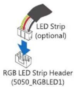
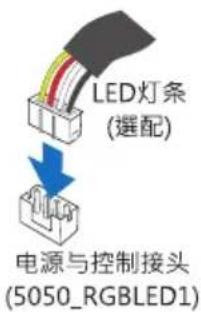
5050\_RGBLED1: RGB LED Strip (5050 SMD) Header
This header providers 12V power and RGB control pins for RGB LED strip (5050 SMD).
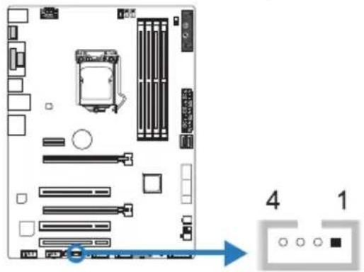
| Pin Assignment |
| 1 VCC12 |
| 2 LED_GREEN |
| 3 LED_RED |
| 4 LED_BLUE |
Note
» Ensure proper pin connecting to your LED strips, wrong connection may damage your LED strips or motherboard.
2.8 Buttons & LEDs
Touch Buttons
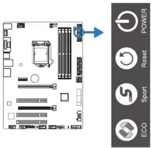
ECO Mode:
Enabled ECO mode, it allows you save energy by slightly reducing system performance.
Sport Mode:
Enabled Sport mode, it allows you to maximize system performance but may use more energy.
Reset:
Touch this button to reboot the system.
Power:
Touch this button to turn-on/off the system.
Note
» ECO/SPORT mode buttons will only be available when running RACING GT Utility in Windows environment.
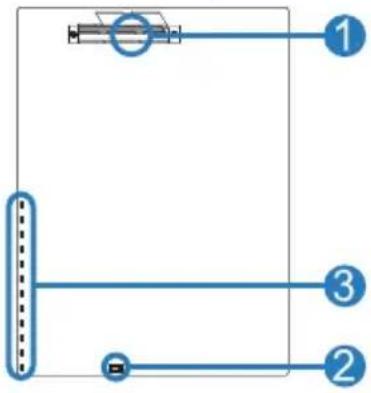
LEDs
Below LEDs are controlled by RACING GT program. Please refer to Chapter 3.3 for more detail software setting.
flowchart
graph TD
    A["Step 1"] --> B["Step 2"]
    B --> C["Step 3"]
- MOSFET Heatsink LED
- RGB LED Strip Header (LED Strip is optional)
- on-board LEDs (x12)
Chapter 3: UEFI BIOS & Software
3.1 UEFI BIOS Setup
- The BIOS Setup program can be used to view and change the BIOS settings for the computer. The BIOS Setup program is accessed by pressing the
key after the Power-On Self-Test (POST) memory test begins and before the operating system boot begins. - For further information of setting up the UEFI BIOS, please refer to the UEFI BIOS Manual on our website.
3.2 BIOS Update
The BIOS can be updated using either of the following utilities:
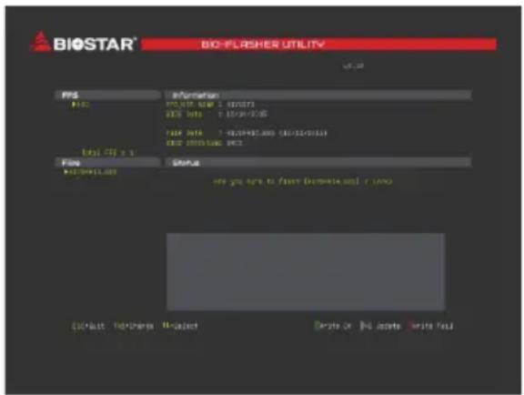
- BIOSTAR BIOS Flasher: Using this utility, the BIOS can be updated from a file on a hard disk, a USB drive (a flash drive or a USB hard drive), or a CD-ROM.
- BIOSTAR BIOS Update Utility: It enables automated updating while in the Windows environment. Using this utility, the BIOS can be updated from a file on a hard disk, a USB drive (a flash drive or a USB hard drive), or a CD-ROM, or from the file location on the Web.
BIOSTAR BIOS Flasher
Note
» This utility only allows storage device with FAT32/16 format and single partition.
» Shutting down or resetting the system while updating the BIOS will lead to system boot failure.
Updating BIOS with BIOSTAR BIOS Flasher
- Go to the website to download the latest BIOS file for the motherboard.
- Then, copy and save the BIOS file into a USB flash (pen) drive.
- Insert the USB pen drive that contains the BIOS file to the USB port.
-
Power on or reset the computer and then press
during the POST process. -
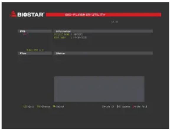
After entering the POST screen, the BIOS-FLASHER utility pops out. Choose
to search for the BIOS file.
-
Select the proper BIOS file, and a message asking if you are sure to flash the BIOS file. Click "Yes" to start updating BIOS.
-
A dialog pops out after BIOS flash is completed, asking you to restart the system. Press the
key to restart system. -
While the system boots up and the full screen logo shows up, press
key to enter BIOS setup.
After entering the BIOS setup, please go to the
BIOS Update Utility (through the Internet)
- Installing BIOS Update Utility from the DVD Driver.
-
Please make sure the system is connected to the internet before using this function.
-
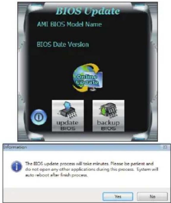
Launch BIOS Update Utility and click the "Online Update" button on the main screen.
-
An open dialog will show up to request your agreement to start the BIOS update. Click "Yes" to start the online update procedure.
-
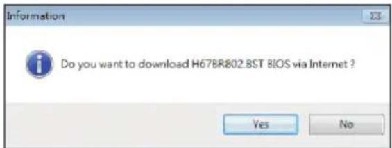
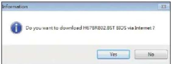
If there is a new BIOS version, the utility will ask you to download it. Click "Yes" to proceed.
-
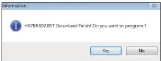
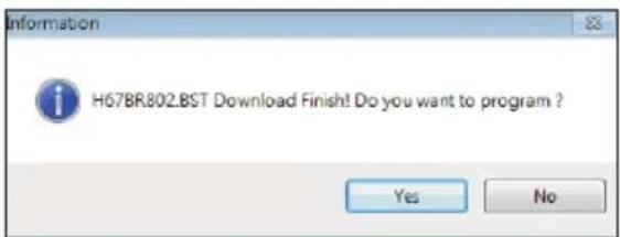
After the download is completed, you will be asked to program (update) the BIOS or not. Click "Yes" to proceed.
-
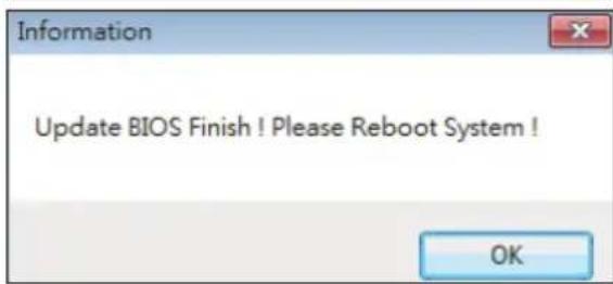
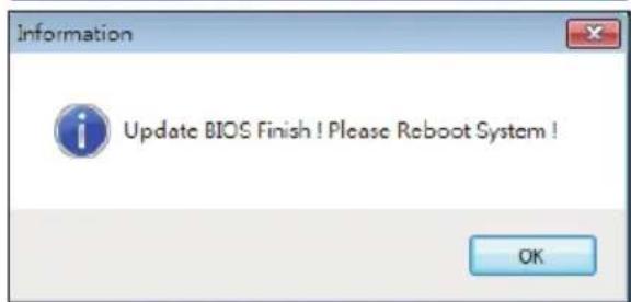
After the updating process is finished, you will be asked you to reboot the system. Click "OK" to reboot.
- While the system boots up and the full screen logo shows up, press
key to enter BIOS setup.
After entering the BIOS setup, please go to the
BIOS Update Utility (through a BIOS file)
- Installing BIOS Update Utility from the DVD Driver.
-
Download the proper BIOS from http://www.biostar.com.tw/
-
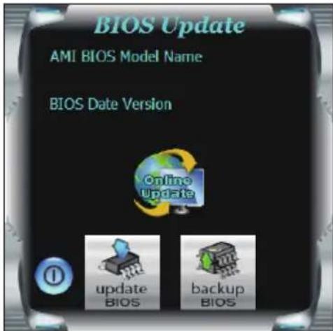
Launch BIOS Update Utility and click the "Update BIOS" button on the main screen.
-
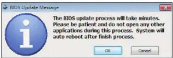
A warning message will show up to request your agreement to start the BIOS update. Click "OK" to start the update procedure.
-
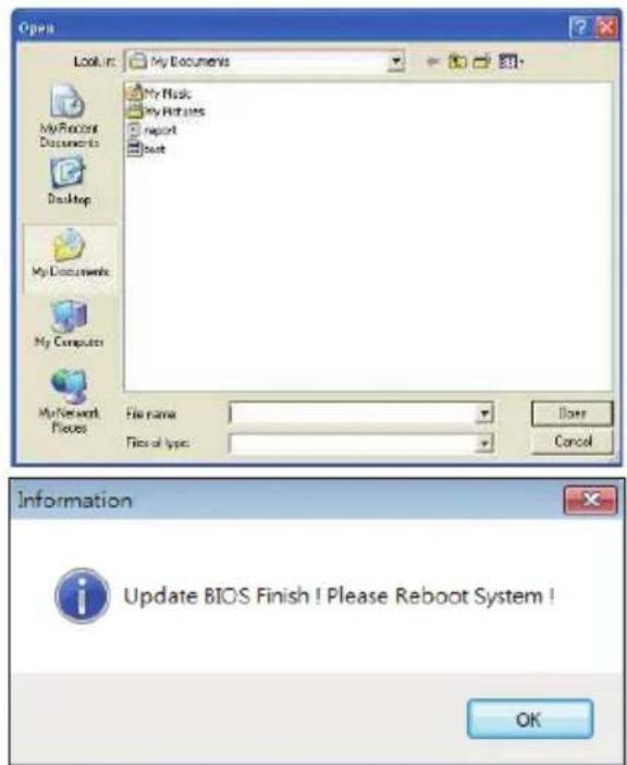
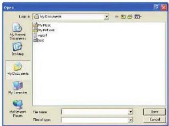
Choose the location for your BIOS file in the system. Please select the proper BIOS file, and then click on "Open". It will take several minutes, please be patient.
-
After the BIOS Update process is finished, click on "OK" to reboot the system.
-
While the system boots up and the full screen logo shows up, press
key to enter BIOS setup.
After entering the BIOS setup, please go to the
Backup BIOS
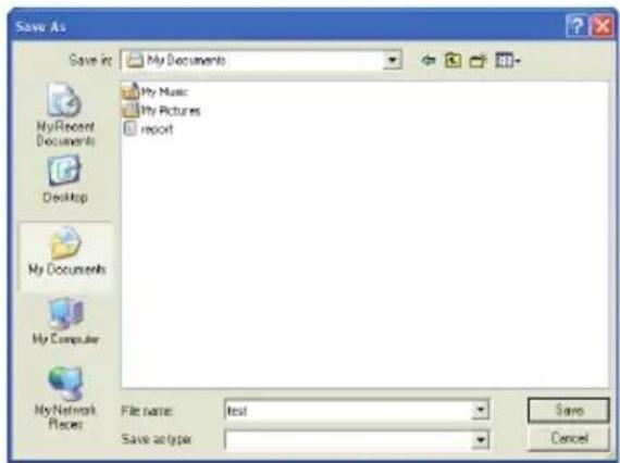
Click the Backup BIOS button on the main screen for the backup of BIOS, and select a proper location for your backup BIOS file in the system, and click "Save".
3.3 Software
Installing Software
- Insert the Setup DVD to the optical drive. The driver installation program would appear if the Auto-run function has been enabled.
- Select Software Installation, and then click on the respective software title.
- Follow the on-screen instructions to complete the installation.
Launching Software
After the installation process is completed, you will see the software icon showing on the desktop. Double-click the icon to launch it.
Note
» All the information and content about following software are subject to be changed without notice. For better performance, the software is being continuously updated.
» The information and pictures described below are for your reference only. The actual information and settings on board may be slightly different from this manual.
BIOScreen Utility
This utility allows you to personalize your boot logo easily. You can choose BMP as your boot logo so as to customize your computer.
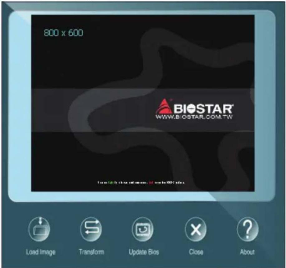
Please follow the step-by-step instructions below to update boot logo:
- Load Image: Choose the picture as the boot logo.
- Transform: Transform the picture for BIOS and preview the result.
- Update Bios: Write the picture to BIOS Memory to complete the update.
eHot-Line
eHot-Line is a convenient utility that helps you to contact with our Tech-Support system. This utility will collect the system information which is useful for analyzing the problem you may have encountered, and then send these information to our tech-support department to help you fix the problem.
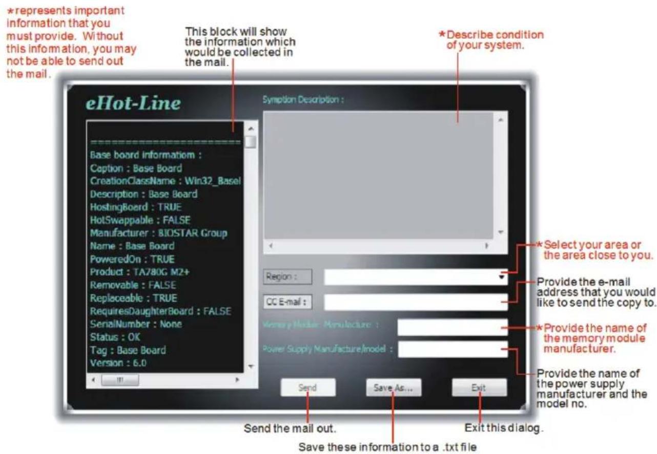
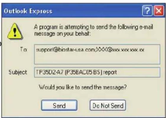
After filling up this information, click "Send" to send the mail out. A warning dialog would appear asking for your confirmation; click "Send" to confirm or "Do Not Send" to cancel.
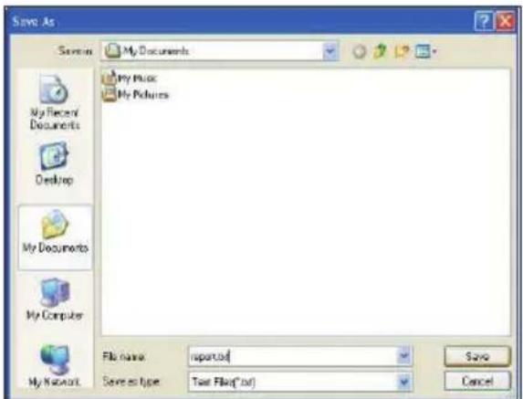
If you want to save this information to a .txt file, click "Save As..." and then you will see a saving dialog appears asking you to enter file name.
Enter the file name and then click "Save". Your system information will be saved to a .txt file.
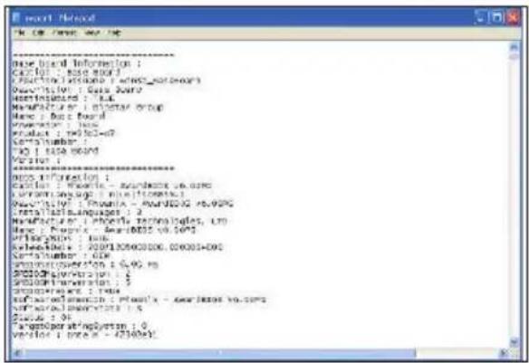
Open the saved .txt file, you will see your system information including motherboard/BIOS/CPU/video/device/OS information. This information is also concluded in the sent mail.
Note
» Before you use this utility, please set Outlook Express as your default e-mail client application program.
» We will not share customer's data with any other third parties, so please feel free to provide your system information while using eHot-Line service.
» If you are not using Outlook Express as your default e-mail client application, you may need to save the system information to a .txt file and send the file to our tech support with other e-mail application. Go to the following website http://www.biostar.com.tw/app/en/about/contact.php for getting our contact information.
RACING GT
RACING GT is an easy-to-use program that integrates several BIOSTAR utilities and allows users to configure these utilities simultaneously and seamlessly.
System Information
This System Information tab provides you an overview of the basic system information.
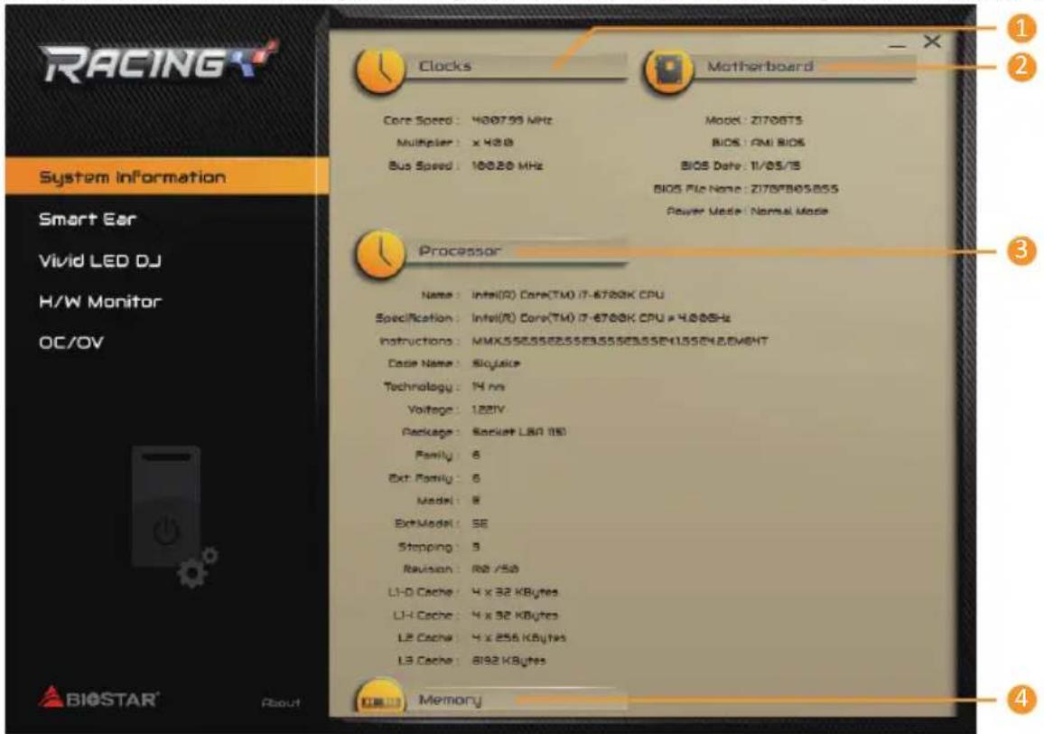
- Clocks: Shows core speed, multiplier and bus speed.
- Motherboard: Shows motherboard information.
- Processor: Shows CPU information.
- Memory: Shows memory information.
SmartEAR
Smart EAR allows you to control system volume and adjust impedance setting (Low/High Gain) to optimize your headphone performance. You can easily enjoy high-quality and awesome sound.
Requirements:
- A chassis with front audio output jacks
- An earphone or a headphone
- Windows 7/8.1(64bit)/10(64bit) operation system
Installation Guide:
- Make sure the front audio cable of the chassis connected to the front audio header of the motherboard properly.
- Install the RACING GT program from the driver DVD.
- Connect the earphone or headphone to the front audio jack of the chassis or audio line-out port of rear I/Os.
» If you want to use an AC'97 front audio output cable, please disable the "Front Panel Jack Detection" setting. This setting can be found via O.S. Audio Utility.
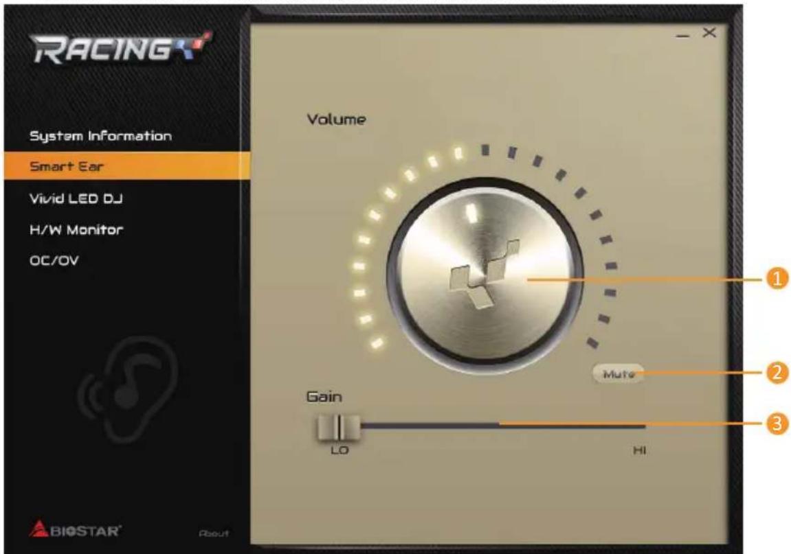
- Volume Control Knob: The volume can be finely adjusted by turning the knob either clockwise or anti-clockwise to increase or decrease system volume accordingly.
- Mute: To disable system sound.
- High/Low Gain Switch: Keep the gain switch to low for low impedance headphone and set to high for high impedance headphone.
Vivid LED DJ
Vivid LED DJ can adjust your color scheme of on-board LEDs, MOSFET Heatsink LED and RGB LED Strip.
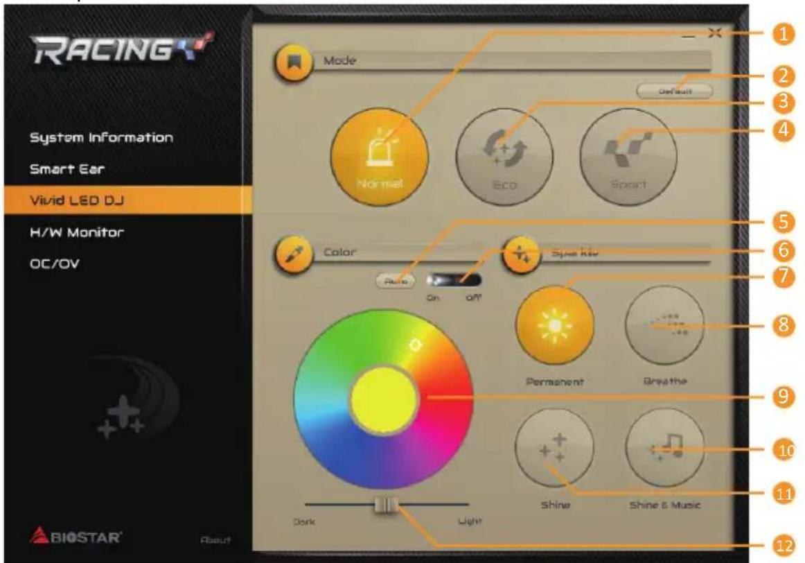
- Normal Mode: It balances energy consumption and system performance.
- Default: All the setting are back to default.
- ECO Mode: It saves energy by slightly reducing system performance.
- Sport Mode: It provides the highest level of performance
» ECO & Sport onboard buttons and LED lights will be available when running RACING GT program in Windows environment.
» The color schemes of Normal, ECO & Sport mode can be adjusted by below setting items.
- Auto: LEDs will automatically change the color.
- LED On/Off: Turn on or off the LEDs.
- Permanent: LEDs are constantly lit.
- Breath: LEDs gradually flash on and off.
- Color Palette: Allows to you choose specific color of the LEDs.
- Shine: LEDs flash at a specific frequency.
- Shine & Music: LEDs will flash according the music played on your system.
» Please make sure your speaker or earphone is properly connected to audio jack before using RACING GT program.
- Light/Dark: Allows you to adjust the LED brightness.
H/W Monitor
The HW Monitor tab allows you to monitor hardware voltage, fan speed, and temperature.
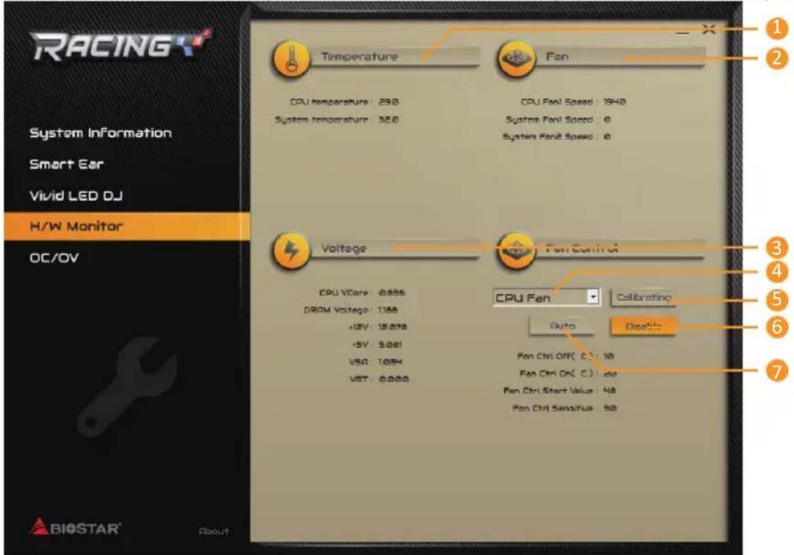
- Temperature: Shows the current CPU and system temperature.
- Fan: Shows the current fans' speed.
- Voltage: Shows the current voltages of CPU and memory.
- CPU Fan/System Fan: Chooses your setting fan.
- Calibration: Calibrates fan speed.
- Disable: Disables smart fan function.
- Auto: Enables smart fan function.
OC/OV
The OC/OV tab allows you to save or load the OC/OV setting profiles, change system frequency and voltage settings.
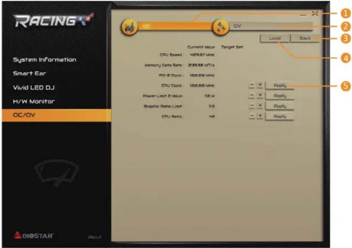
- OC: Allows you to adjust overclocking profile values.
- OV: Allows you to adjust voltage profile values.
- Save: Store the profile values for future use.
- Load: Load the profile values from the file.
- Apply: Apply your changes.
Note
» Not all types of CPU perform above overclock setting ideally; the difference will be based on the selected CPU model.
» Overclock is an optional process, but not a “must-do” process; it is not recommended for inexperienced users. Therefore, we will not be responsible for any hardware damage which may be caused by overclocking. We also would not guarantee any overclocking performance.
» OC/OV tab is only for Z170 motherboard.
Chapter 4: Useful help
4.1 Driver Installation
After you installed your operating system, please insert the Fully Setup Driver DVD into your optical drive and install the driver for better system performance.
You will see the following window after you insert the DVD
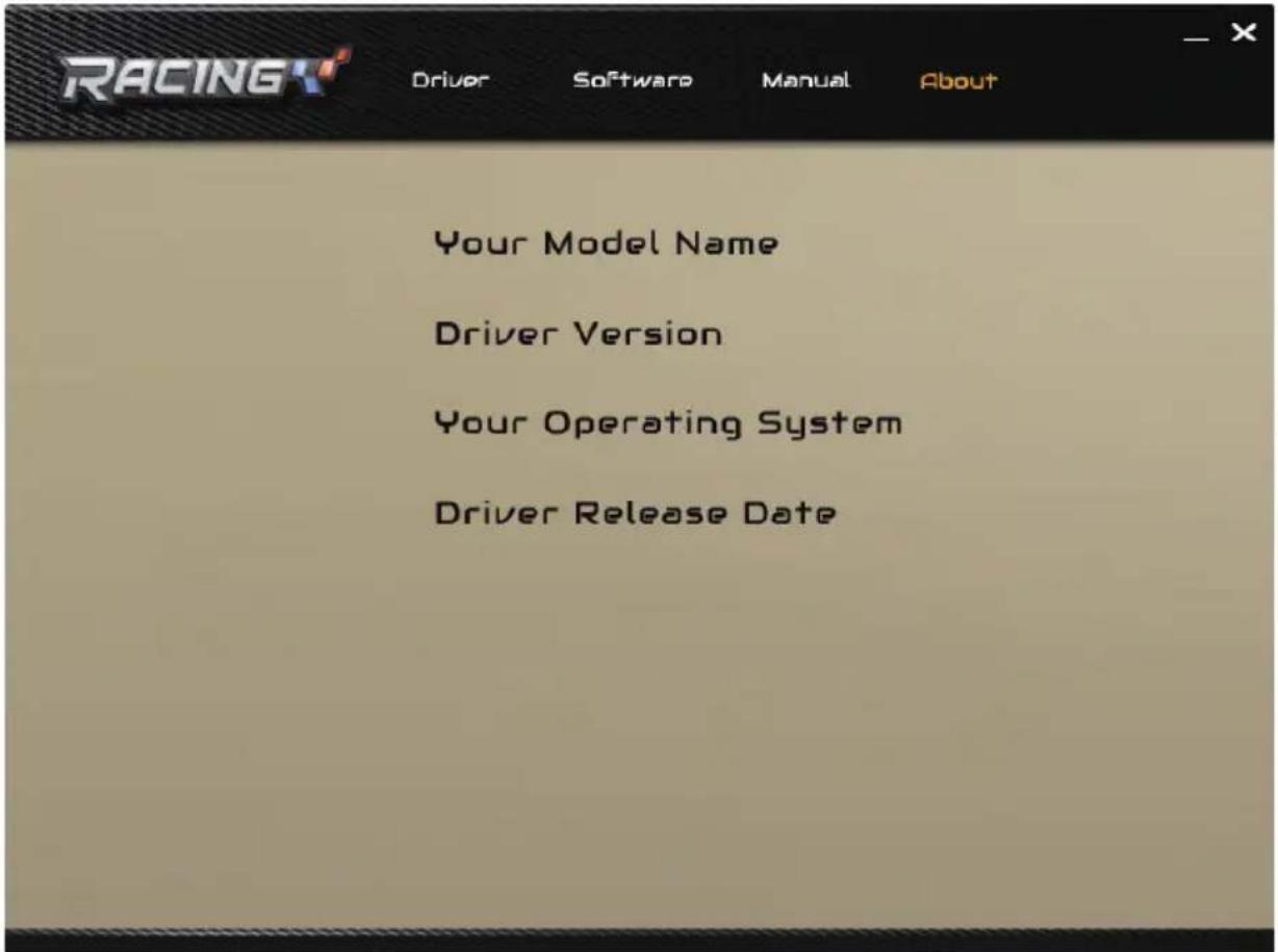
The setup guide will auto detect your motherboard and operating system.
A. Driver Installation
To install the driver, please click on the Driver icon. The setup guide will list the compatible driver for your motherboard and operating system. Click on each device driver to launch the installation program.
B. Software Installation
To install the software, please click on the Software icon. The setup guide will list the software available for your system, click on each software title to launch the installation program.
C. Manual
Aside from the paperback manual, we also provide manual in the Driver DVD. Click on the Manual icon to browse for available manual.
Note
» If this window didn't show up after you insert the Driver DVD, please use file browser to locate and execute the file SETUP.EXE under your optical drive.
» You will need Acrobat Reader to open the manual file. Please download the latest version of Acrobat Reader software from http://get.adobe.com/reader/
4.2 AMI BIOS Beep Code
Boot Block Beep Codes
| Number of Beeps Description |
| Continuing Memory sizing error or Memory module not found |
POST BIOS Beep Codes
| Number of Beeps Description | |
| 1 Success booting. | |
| 8 Display memory error | (system video adapter) |
4.3 AMI BIOS post code
| Code Description |
| 10 PEI Core is started |
| 11 Pre-memory CPU initialization is started |
| 15 Pre-memory North Bridge initialization is started |
| 19 Pre-memory South Bridge initialization is started |
| 2B Memory initialization. Serial Presence Detect (SPD) data reading |
| 2C Memory initialization. Memory presence detection |
| 2D Memory initialization. Programming memory timing information |
| 2E Memory initialization. Configuring memory |
| 2F Memory initialization (other). |
| 31 Memory Installed |
| 32 CPU post-memory initialization is started |
| 33 CPU post-memory initialization. Cache initialization |
| 34 CPU post-memory initialization. Application Processor(s) (AP) initialization |
| 35 CPU post-memory initialization. Boot Strap Processor (BSP) selection |
| 36 CPU post-memory initialization. System Management Mode (SMM) initialization |
| 37 Post-Memory North Bridge initialization is started |
| 3B Post-Memory North Bridge initialization (North Bridge module specific) |
| 4F DXE IPL is started |
| 60 DXE Core is started |
| F0 Recovery condition triggered by firmware (Auto recovery) |
| F1 Recovery condition triggered by user (Forced recovery) |
| F2 Recovery process started |
| F3 Recovery firmware image is found |
| F4 Recovery firmware image is loaded |
| E0 S3 Resume is stared (S3 Resume PPI is called by the DXE IPL) |
| E1 S3 Boot Script execution |
| E2 Video repost |
| E3 OS S3 wake vector call |
| 60 DXE Core is started |
| 61 NVRAM initialization |
| 62 Installation of the South Bridge Runtime Services |
| 63 CPU DXE initialization is started |
| 68 PCI host bridge initialization |
| 69 North Bridge DXE initialization is started |
| 6A North Bridge DXE SMM initialization is started |
| 70 South Bridge DXE initialization is started |
| 71 South Bridge DXE SMM initialization is started |
| 72 South Bridge devices initialization |
| 78 South Bridge DXE Initialization (South Bridge module specific) |
| 79 ACPI module initialization |
| 90 Boot Device Selection (BDS) phase is started |
| 91 Driver connecting is started |
| 92 PCI Bus initialization is started |
| 93 PCI Bus Hot Plug Controller Initialization |
| 94 PCI Bus Enumeration |
| 95 PCI Bus Request Resources |
| 96 PCI Bus Assign Resources |
| 97 Console Output devices connect |
| 98 Console input devices connect |
| 99 Super IO Initialization |
| 9A USB initialization is started |
| 9B USB Reset |
| 9C USB Detect |
| 9D USB Enable |
| A0 IDE initialization is started |
| A1 IDE Reset |
| A2 IDE Detect |
| A3 IDE Enable |
| A4 SCSI initialization is started |
| A5 SCSI Reset |
| A6 SCSI Detect |
| A7 SCSI Enable |
| A8 Setup Verifying Password |
| A9 Start of Setup |
| AB Setup Input Wait |
| AD Ready To Boot event |
| AE Legacy Boot event |
| AF Exit Boot Services event |
| B0 Runtime Set Virtual Address MAP Begin |
| B1 Runtime Set Virtual Address MAP End |
| B2 Legacy Option ROM Initialization |
| B3 System Reset |
| B4 USB hot plug |
| B5 PCI bus hot plug |
| B6 Clean-up of NVRAM |
| B7 Configuration Reset (reset of NVRAM settings) |
4.4 Troubleshooting
| Probable Solution | |
| 1. There is no power in the system. Power LED does not shine; the fan of the power supply does not work2. Indicator light on keyboard does not shine. | 1. Make sure power cable is securely plugged in.2. Replace cable.3. Contact technical support. |
| System is inoperative. Keyboard lights are on, power indicator lights are lit, and hard drives are running. | Using even pressure on both ends of the DIMM, press down firmly until the module snaps into place. |
| System does not boot from a hard disk drive, but can be booted from optical drive. | 1. Check cable running from disk to disk controller board. Make sure both ends are securely plugged in; check the drive type in the standard CMOS setup.2. Backing up the hard drive is extremely important. All hard disks are capable of breaking down at any time. |
| System only boots from an optical drive. Hard disks can be read, applications can be used, but system fails to boot from a hard disk. | 1. Back up data and applications files.2. Reformat the hard drive. Re-install applications and data using backup disks. |
| Screen message shows “Invalid Configuration” or “CMOS Failure.” | Review system’s equipment. Make sure correct information is in setup. |
| System cannot boot after user installs a second hard drive. | 1. Set master/slave jumpers correctly.2. Run SETUP program and select correct drive types. Call the drive manufacturers for compatibility with other drives. |
CPU Overheated
If the system shutdown automatically after power on system for seconds, that means the CPU protection function has been activated.
When the CPU is over heated, the motherboard will shutdown automatically to avoid a damage of the CPU, and the system may not power on again.
In this case, please double check:
- The CPU cooler surface is placed evenly with the CPU surface.
- CPU fan is rotated normally.
- CPU fan speed is fulfilling with the CPU speed.
After confirmed, please follow steps below to relief the CPU protection function.
- Remove the power cord from power supply for seconds.
- Wait for seconds.
- Plug in the power cord and boot up the system.
Or you can:
- Clear the CMOS data. (See "Close CMOS Header: JCMOS1" section)
- Wait for seconds.
- Power on the system again.
4.5 RAID Functions
RAID Definitions
flowchart
graph TD
    A["RAID 0 striping"] --> B["Block 1"]
    A --> C["Block 2"]
    B --> D["Disk 1"]
    C --> E["Disk 2"]
    D --> F["Block 5"]
    E --> G["Block 4"]
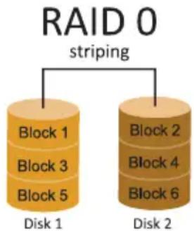
In a RAID 0 system data are split up in blocks that get written across all the drives in the array. By using multiple disks (at least 2) at the same time, this offers superior I/O performance. This performance can be enhanced further by using multiple controllers, ideally one controller per disk.
Features and Benefits
- Drives: Minimum 2, and maximum is up to 6 or 8. Depending on the platform.
- Uses: Intended for non-critical data requiring high data throughput, or any environment that does not require fault tolerance.
- Benefits: provides increased data throughput, especially for large files. No capacity loss penalty for parity.
- Drawbacks: Does not deliver any fault tolerance. If any drive in the array fails, all data is lost.
- Fault Tolerance: No.
• Total Capacity: (Minimal. HDD Capacity) x (Connected HDDs Amount)
flowchart
graph TD
    A["Block 1\nBlock 2\nBlock 3\nDisk 1"] --> B["Block 1\nBlock 2\nBlock 3"]
    C["Block 1\nBlock 2\nBlock 3\nDisk 2"] --> D["Block 1\nBlock 2\nBlock 3"]
    E["RAID 1 mirroring"] --> F["Block 1\nBlock 2\nBlock 3"]
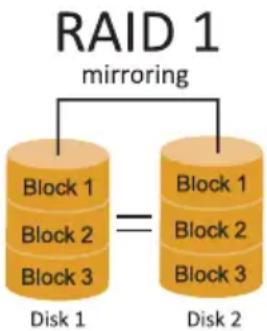
Data are stored twice by writing them to both the data disk (or set of data disks) and a mirror disk (or set of disks). If a disk fails, the controller uses either the data drive or the mirror drive for data recovery and continues operation. You need at least 2 disks for a RAID 1 array.
Features and Benefits
- Drives: Minimum 2, and maximum is 2.
- Uses: RAID 1 is ideal for small databases or any other application that requires fault tolerance and minimal capacity.
- Benefits: Provides 100% data redundancy. Should one drive fail, the controller switches to the other drive.
- Drawbacks: Requires 2 drives for the storage space of one drive. Performance is impaired during drive rebuilds.
- Fault Tolerance: Yes.
RAID 10 (1+0)
flowchart
graph TD
    A["Block 1\nBlock 3\nBlock 5\nDisk 1"] --> B["Block 1\nBlock 3\nBlock 5"]
    C["Block 2\nBlock 4\nBlock 6\nDisk 3"] --> D["Block 2\nBlock 4\nBlock 6"]
    E["Block 2\nBlock 4\nBlock 6"] --> F["Block 2\nBlock 4\nBlock 6"]
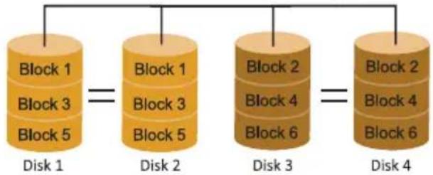
RAID 10 combines the advantages (and disadvantages) of RAID 0 and RAID 1 in one single system. It provides security by mirroring all data on a secondary set of disks (disk 3 and 4 in the drawing below) while using striping across each set of disks to speed up data transfers.
Features and Benefits
- Drives: Minimum 4, and maximum is 6 or 8, depending on the platform.
- Benefits: Optimizes for both fault tolerance and performance, allowing for automatic redundancy. May be simultaneously used with other RAID levels in an array, and allows for spare disks.
- Drawbacks: Requires twice the available disk space for data redundancy, the same as RAID level 1.
- Fault Tolerance: Yes.
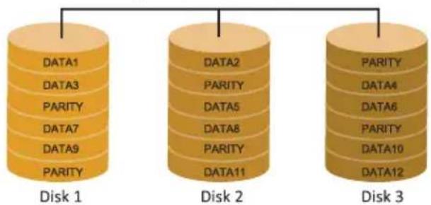
RAID 5
parity across disks
flowchart
graph TD
    A["DATA1"] --> B["Disk 1"]
    C["DATA3"] --> B
    D["PARITY"] --> B
    E["DATA7"] --> B
    F["DATA9"] --> B
    G["PARITY"] --> B
    H["DATA2"] --> I["Disk 2"]
    J["PARITY"] --> I
    K["DATA5"] --> I
    L["PARITY"] --> I
    M["DATA8"] --> I
    N["PARITY"] --> I
    O["DATA11"] --> I
    P["PARITY"] --> Q["Disk 3"]
    R["PARITY"] --> Q
    S["DATA4"] --> Q
    T["DATA6"] --> Q
    U["PARITY"] --> Q
    V["DATA10"] --> Q
    W["DATA12"] --> Q
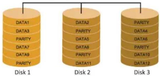
A RAID 5 array can withstand a single disk failure without losing data or access to data. Although RAID 5 can be achieved in software, a hardware controller is recommended. Often extra cache memory is used on these controllers to improve the write performance.
Features and Benefits
• Drives: Minimum 3.
• Uses: RAID 5 is recommended for transaction processing and general purpose service.
- Benefits: An ideal combination of good performance, good fault tolerance, and high capacity and storage efficiency.
- Drawbacks: Individual block data transfer rate same as a single disk. Write performance can be CPU intensive.
- Fault Tolerance: Yes.
Note
» For more details settings about Intel® Rapid Storage Technology (Intel® RST), please visit http://www.intel.com/p/en_US/support/highlights/chpsts/imsm
» PCI-E Storage only supports RAID 0, 1 & 5.
APPENDIX I: Specifications in Other Languages
Arabic
| المواصفات | |
| Intel® Core i7 / i5 / i3 / Pentium / Celeron الماخذ 1151 لمعالج ايه им دي الحد الأقصى للطاقة الحرariansية في نصمين المعالجCPU لقائمة دعم المعالج | freqادة وحدة المعالجة المركزية |
| INTEL® Z170 (Z170GT5) INTEL® B150 (B150GT5) | محموعة الشرانج |
| 2133/1866 DDR4. دی. ار. 3200(OC) (Z170GT5) DDR4. دی. ار. 4DIMM فتحات الذاكرة المزدوچة DDR4. دی. ار. 6 6 6 DDR4 16/8/4 ECC ت二十五 دون DIMM کل فتحة مزدوچة 4x 4x www.biostar.com.tw لقائمة دعم الذاكرة. * | الذاكرة |
| INTEL® Z170: SATA III (6Gb/s) 2x وصلة 1x SATA Express (16Gb/s) وصلة 4x SATA III (6Gb/s) وصلة 4x SATA III (6Gb/s) وصلة 1x SATA Express (16Gb/s) وصلة 4x SATA III (6Gb/s) وصلة 4x SATA III (6Gb/s) وصلة 4x SATA III (6Gb/s) وصلة 4x SATA III (6Gb/s) وصلة 4x SATA III (6Gb/s) وصلة 4x SATA III (6Gb/s) وصلة 4x SATA III (6Gb/s) وصلة 4x SATA III (6Gb/s) وصلة 1x SATA Express (16Gb/s) وصلة 4x SATA III (6Gb/s) وصلة 4x SATA III (6Gb/s) وصلة 4x SATA III (6Gb/s) وصلة 4x SATA III (6Gb/s) وصلة | التخزين |
| Intel i219V ميجابيت / الثانية ، تحديد تلقاني ، النسف / الفردة القصوى المزدوچة | LAN شبكة محليية |
| ALC892 Hi-Fi (Rear + Front), 7.1 قنوات عالية 의فة | الترميز الصوتي |
| ( من خلال الموزع الذاخلي) 4) 3.0 USB 6 6 6 6 6 6 6 6 6 6 6 6 6 6 6 6 6 6 6 6 6 6 6 6 6 6 6 6 6 6 6 6 6 6 6 6 6 6 6 6 6 6 6 6 6 6 6 6 6 6 1 x 3.0 PCIe فتحة mentalحقاقات الإضافية 1 x 3.0 PCIe فتحة mentalحقاقات الإضافية 1 x 3.0 PCIe فتحة mentalحقاقات الإضافية 1 x 3.0 PCIe فتحة mentalحقاقات الإضافية 1 x 3.0 PCIe فتحة mentalحقاقات الإضافية 1 x 3.0 PCIe فتحة mentalحقاقات الإضافية 1 x 3.0 PCIe ف Close 1 x 3.0 PCIe ف Close 1 x 3.0 PCIe ف Close 1 x 3.0 PCIe ف Close 1 x 3.0 PCIe ف Close 1 x 3.0 PCIe ف Close 1 x 3.0 PCIe ف Close 1 x 3.0 PCIe ف Close 1 x 3.0 PCIe ف Close 1 x 3.0 PCIe ف Close 1 x 3.0 PCIe فClose 1 x 3.0 PCIe ف Close 1 x 3.0 PCIe ف Close 1 x 3.0 PCIe ف Close 1 x 3.0 PCIe ف Close 1 x 3.0 PCIe ف Close 1 x 3.0 PCIe ف Close 1 x 3.0 PCIe ف Close 1 x 3.0 PCIe ف Close 1 x 3.0 PCIe ف Close 1 x 3.0 PCIe ف close 1 x 3.0 PCIe ف Close 1 x 3.0 PCIe ف Close 1 x 3.0 PCIe ف Close 1 x 3.0 PCIe ف Close 1 x 3.0 PCIe ف Close 1 x 3.0 PCIe ف Close 1 x 3.0 PCIe ف Close 1 x 3.0 PCIe ف Close 1 x 3.0 PCIe ف Close 1 x 3.0 PCIe فclose 1 x 3.0 PCIe ف Close 1 x 3.0 PCIe ف Close 1 x 3.0 PCIe ف Close 1 x 3.0 PCIe ف Close 1 x 3.0 PCIe ف Close 1 x 3.0 PCIe ف Close 1 x 3.0 PCIe ف Close 1 x 3.0 PCIe ف Close 1 x 3.0 PCIe ف Close 1 x 3.0 PCIe ف_end 1 x 3.0 PCIe ف Close 1 x 3.0 PCIe ف Close 1 x 3.0 PCIe ف Close 1 x 3.0 PCIe ف Close 1 x 3.0 PCIe ف Close 1 x 3.0 PCIe ف Close 1 x 3.0 PCIe ف Close 1 x 3.0 PCIe ف Close 1 x 3.0 PCIe ف Close 1 x 3.0 PCIe ف End 1 x 3.0 PCIe ف Close 1 x 3.0 PCIe ف Close 1 x 3.0 PCIe ف Close 1 x 3.0 PCIe ف Close 1 x 3.0 PCIe ف Close 1 x 3.0 PCIe ف Close 1 x 3.0 PCIe ف Close 1 x 3.0 PCIe ف Close 1 x 3.0 PCIe ف Close 1 x 3.0 PCIe ف Closed 1 x 3.0 PCIe ف Close 1 x 3.0 PCIe ف Close 1 x 3.0 PCIe ف Close 1 x 3.0 PCIe ف Close 1 x 3.0 PCIe ف Close 1 x 3.0 PCIe ف Close 1 x 3.0 PCIe ف Close 1 x 3.0 PCIe ف Close 1 x 3.0 PCIe ف Close 1 x 3.0 PCIe ف Open 1 x 3.0 PCIe ف Close 1 x 3.0 PCIe ف Close 1 x 3.0 PCIe ف Close 1 x 3.0 PCIe ف Close 1 x 3.0 PCIe ف Close 1 x 3.0 PCIe ف Close 1 x 3.0 PCIe ف Close 1 x 3.0 PCIe ف Close 1 x 3.0 PCIe ف Close 1 x 3.0 PCIe فOpen 1 x 3.0 PCIe ف Close 1 x 3.0 PCIe ف Close 1 x 3.0 PCIe ف Close 1 x 3.0 PCIe ف Close 1 x 3.0 PCIe ف Close 1 x 3.0 PCIe ف Close 1 x 3.0 PCIe ف Close 1 x 3.0 PCIe ف Close 1 x 3.0 PCIe ف Close 1 x 3.0 PCIe ف Conoc 1 x 3.0 PCIe ف Close 1 x 3.0 PCIe ف Close 1 x 3.0 PCIe ف Close 1 x 3.0 PCIe ف Close 1 x 3.0 PCIe ف Close 1 x 3.0 PCIe ف Close 1 x 3.0 PCIe ف Close 1 x 3.0 PCIe ف Close 1 x 3.0 PCIe ف Close 1 x 3.0 PCIe فConoc 1 x 3.0 PCIe ف Close 1 x 3.0 PCIe ف Close 1 x 3.0 PCIe ف Close 1 x 3.0 PCIe ف Close 1 x 3.0 PCIe ف Close 1 x 3.0 PCIe ف Close 1 x 3.0 PCIe ف Close 1 x 3.0 PCIe ف Close 1 x 3.0 PCIe ف Close 1 x 3.0 PCIe φ Close 1 x 3.0 PCIe φ Close 1 x 3.0 PCIe φ Close 1 x 3.0 PCIe φ Close 1 x 3.0 PCIe φ Close 1 x 3.0 PCIe φ Close 1 x 3.0 PCIe φ Close 1 x 3.0 PCIe φ Close 1 x 3.0 PCIe φ Close 1 x 3.0 PCIe φ Close 1 x 3.0 PCIeφ Close 1 x 3.0 PCIe φ Close 1 x 3.0 PCIe φ Close 1 x 3.0 PCIe φ Close 1 x 3.0 PCIe φ Close 1 x 3.0 PCIe φ Close 1 x 3.0 PCIe φ Close 1 x 3.0 PCIe φ Close 1 x 3.0 PCIe φ Close 1 x 3.0 PCIe φ Close 1 x 3.0 PCIe γΕΕΟΥΜΑΟΥΜΑΟΥΜΑΟΥΜΑΟΥΜΑΟΥΜΑΟΥΜΑΟΥΜΑΟΥΜΑΟΥΜΑΟΥΜΑΟΥΜΑΟΥΜΑΟΥΜΑΟΥΜΑΟΥΜΑΟΥΜΑΟΥΜΑΟΥΜΑΟΥΜΑΟΥΜΑΟΥΜΑΟΥΜΑΟΥΜΑΟΥΜΑΟΥΜΗΟΥΜΗΟΥΜΗΟΥΜΗΟΥΜΗΟΥΜΗΟΥΜΗΟΥΜΗΟΥΜΗΟΥΜΗΟΥΜΗΟΥΜΗΟΥΜΗΟΥΜΗΟΥΜΗΟΥΜΗΟΥΜΗΟΥΜΗΟΥΜΗΟΥΜΗΟΥΜΗΟΥΜΗΟΥΜΗΟΥΜΗΟΥΜΗΟΥΜΑΟΥΜΑΟΥΜΑΟΥΜΑΟΥΜΑΟΥΜΑΟΥΜΑΟΥΜΑΟΥΜΑΟΥΜΑΟΥΜΑΟΥΜΑΟΥΜΑΟΥΜΑΟΥΜΑΟΥΜΑΟΥΜΑΟΥΜΑΟΥΜΑΟΥΜΑΟΥΜΑΟΥΜΑΟΥΜΑΟΥΜΑΟΥΜΜΟΥΜΑΟΥΜΑΟΥΜΑΟΥΜΑΟΥΜΑΟΥΜΑΟΥΜΑΟΥΜΑΟΥΜΑΟΥΜΑΟΥΜΑΟΥΜΑΟΥΜΑΟΥΜΑΟΥΜΑΟΥΜΑΟΥΜΑΟΥΜΑΟΥΜΑΟΥΜΑΟΥΜΑΟΥΜΑΟΥΜΑΟΥΜΑΟΥΜαΟΥΜΑΟΥΜΑΟΥΜΑΟΥΜΑΟΥΜΑΟΥΜΑΟΥΜΑΟΥΜΑΟΥΜΑΟΥΜΑΟΥΜΑΟΥΜΑΟΥΜΑΟΥΜΑΟΥΜΑΟΥΜΑΟΥΜΑΟΥΜΑΟΥΜΑΟΥΜΑΟΥΜΑΟΥΜΑΟΥΜΑΟΥΜΑΟΥΜΒΟΥΜΑΟΥΜΑΟΥΜΑΟΥΜΑΟΥΜΑΟΥΜΑΟΥΜΑΟΥΜΑΟΥΜΑΟΥΜΑΟΥΜΑΟΥΜΑΟΥΜΑΟΥΜΑΟΥΜΑΟΥΜΑΟΥΜΑΟΥΜΑΟΥΜΑΟΥΜΑΟΥΜΑΟΥΜΑΟΥΜΑΟΥΜΑΟΥΜΔΟΥΜΑΟΥΜΑΟΥΜΑΟΥΜΑΟΥΜΑΟΥΜΑΟΥΜΑΟΥΜΑΟΥΜΑΟΥΜΑΟΥΜΑΟΥΜΑΟΥΜΑΟΥΜΑΟΥΜΑΟΥΜΑΟΥΜΑΟΥΜΑΟΥΜΑΟΥΜΑΟΥΜΑΟΥΜΑΟΥΜΑΟΥΜΑΟΥΜΛΟΥΜΑΟΥΜΑΟΥΜΑΟΥΜΑΟΥΜΑΟΥΜΑΟΥΜΑΟΥΜΑΟΥΜΑΟΥΜΑΟΥΜΑΟΥΜΑΟΥΜΑΟΥΜΑΟΥΜΑΟΥΜΑΟΥΜΑΟΥΜΑΟΥΜΑΟΥΜΑΟΥΜΑΟΥΜΑΟΥΜΑΟΥΜΑΟΥΜAΟΥΜΑΟΥΜΑΟΥΜΑΟΥΜΑΟΥΜΑΟΥΜΑΟΥΜΑΟΥΜΑΟΥΜΑΟΥΜΑΟΥΜΑΟΥΜΑΟΥΜΑΟΥΜΑΟΥΜΑΟΥΜΑΟΥΜΑΟΥΜΑΟΥΜΑΟΥΜΑΟΥΜΑΟΥΜΑΟΥΜΑΟΥΜΑΟΥΜΝΟΥΜΑΟΥΜΑΟΥΜΑΟΥΜΑΟΥΜΑΟΥΜΑΟΥΜΑΟΥΜΑΟΥΜΑΟΥΜΑΟΥΜΑΟΥΜΑΟΥΜΑΟΥΜΑΟΥΜΑΟΥΜΑΟΥΜΑΟΥΜΑΟΥΜΑΟΥΜΑΟΥΜΑΟΥΜΑΟΥΜΑΟΥΜΑΟΥΜΚΟΥΜΑΟΥΜΑΟΥΜΑΟΥΜΑΟΥΜΑΟΥΜΑΟΥΜΑΟΥΜΑΟΥΜΑΟΥΜΑΟΥΜΑΟΥΜΑΟΥΜΑΟΥΜΑΟΥΜΑΟΥΜΑΟΥΜΑΟΥΜΑΟΥΜΑΟΥΜΑΟΥΜΑΟΥΜΑΟΥΜΑΟΥΜΑΟΥΜΕΟΥΜΑΟΥΜΑΟΥΜΑΟΥΜΑΟΥΜΑΟΥΜΑΟΥΜΑΟΥΜΑΟΥΜΑΟΥΜΑΟΥΜΑΟΥΜΑΟΥΜΑΟΥΜΑΟΥΜΑΟΥΜΑΟΥΜΑΟΥΜΑΟΥΜΑΟΥΜΑΟΥΜΑΟΥΜΑΟΥΜΑΟΥΜΑΟΥМΑΟΥΜΑΟΥΜΑΟΥΜΑΟΥΜΑΟΥΜΑΟΥΜΑΟΥΜΑΟΥΜΑΟΥΜΑΟΥΜΑΟΥΜΑΟΥΜΑΟΥΜΑΟΥΜΑΟΥΜΑΟΥΜΑΟΥΜΑΟΥΜΑΟΥΜΑΟΥΜΑΟΥΜΑΟΥΜΑΟΥΜΑΟΥΜΑΟΥΚΑΤΙΚΑΤΙΚΑΤΙΚΑΤΙΚΑΤΙΚΑΤΙΚΑΤΙΚΑΤΙΚΑΤΙΚΑΤΙΚΑΤΙΚΑΤΙΚΑΤΙΚΑΤΙΚΑΤΙΚΑΤΙΚΑΤΙΚΑΤΙΚΑΤΙΚΑΤΙΚΑΤΙΚΑΤΙΚΑΤΙΚΑΤΙΚΑΤΙΚΑΤΣΚΑΤΣΚΑΤΣΚΑΤΣΚΑΤΣΚΑΤΣΚΑΤΣΚΑΤΣΚΑΤΣΚΑΤΣΚΑΤΣΚΑΤΣΚΑΤΣΚΑΤΣΚΑΤΣΚΑΤΣΚΑΤΣΚΑΤΣΚΑΤΣΚΑΤΣΚΑΤΣΚΑΤΣΚΑΤΣΚΑΤΣΚΑΤΣΚΑΤSigmaKAMOYMAYOYMAYOYMAYOYMAYOYMAYOYMAYOYMAYOYMAYOYMAYOYMAYOYMAYOYMAYOYMAYOYMAYOYMAYOYMAYOYMAYOYMAYOYMAYOYMAYOYMAYOYMAYOYMAYOYMAYOYMAYOYMABOYMAYOYMAYOYMAYOYMAYOYMAYOYMAYOYMAYOYMAYOYMAYOYMAYOYMAYOYMAYOYMAYOYMAYOYMAYOYMAYOYMAYOYMAYOYMAYOYMAYOYMAYOYMAYOYMAYOYMAYOYMBYOYMAYOYMAYOYMAYOYMAYOYMAYOYMAYOYMAYOYMAYOYMAYOYMAYOYMAYOYMAYOYMAYOYMAYOYMAYOYMAYOYMAYOYMAYOYMAYOYMAYOYMAYOYMAYOYMAYOYMAYOYMACHOGMADOGMADOGMADOGMADOGMADOGMADOGMADOGMADOGMADOGMADOGMADOGMADOGMADOGMADOGMADOGMADOGMADOGMADOGMADOGMADOGMADOGMADOGMADOGMADOGMADOGMADOGMADOGMADOGMADOGMADOGMADOGMADOGMADOGMADOREMADOGMADOGMADOGMADOGMADOGMADOGMADOGMADOGMADOGMADOGMADOGMADOGMADOGMADOGMADOGMADOGMADOGMADOGMADOGMADOGMADOGMADOGMADOGMADOGMADOGMADOGMADOGMADOGMADOGMADOGMADOGMADOGMADOG MADOGMADOGMADOGMADOGMADOGMADOGMADOGMADOGMADOGMADOGMADOGMADOGMADOGMADOGMADOGMADOGMADOGMADOGMADOGMADOGMADOGMADOGMADOGMADOGMADOGMADOGMADOGMADOGMADOGMADOGMADOGMADOGMADOGMAMOYMADOGMADOGMADOGMADOGMADOGMADOGMADOGMADOGMADOGMADOGMADOGMADOGMADOGMADOGMADOGMADOGMADOGMADOGMADOGMADOGMADOGMADOGMADOGMADOGMADOGMADOGMADOGMADOGMADOGMADOGMADOGMADOGMADOGNATGAROYMADOGMADOGMADOGMADOGMADOGMADOGMADOGMADOGMADOGMADOGMADOGMADOGMADOGMADOGMADOGMADOGMADOGMADOGMADOGMADOGMADOGMADOGMADOGMADOGMADOGMADOGMADOGMADOGMADOGMADOGMADOGMADOGMAMOYAOMOYAOMOYAOMOYAOMOYAOMOYAOMOYAOMOYAOMOYAOMOYAOMOYAOMOYAOMOYAOMOYAOMOYAOMOYAOMOYAOMOYAOMOYAOMOYAOMOYAOMOYAOMOYAOMOYAOMOYAOMOYAOMOYAOMOYAOMOYAOMOYAOMOYAOMOYAOMOYAOMOYAOMoYOMaTOKOYMADOGMADOGMADOGMADOGMADOGMADOGMADOGMADOGMADOGMADOGMADOGMADOGMADOGMADOGMADOGMADOGMADOGMADOGMADOGMADOGMADOGMADOGMADOGMADOGMADOGMADOGMADOGMADOGMADOGMADOGMADOGMADOGMAdOGMADOGMADOGMADOGMADOGMADOGMADOGMADOGMADOGMADOGMADOGMADOGMADOGMADOGMADOGMADOGMADOGMADOGMADOGMADOGMADOGMADOGMADOGMADOGMADOGMADOGMADOGMADOGMADOGMADOGMADOGMADOGMADOGMADONGMADONGMADONGMADONGMADONGMADONGMADONGMADONGMADONGMADONGMADONGMADONGMADONGMADONGMADONGMADONGMADONGMADONGMADONGMADONGMADONGMADONGMADONGMADONGMADONGMADONGMADONGMADONGMADONGMADONGMADONGMADONGMADONGMADONG MADONG MADONG MADONG MADONG MADONG MADONG MADONG MADONG MADONG MADONG MADONG MADONG MADONG MADONG MADONG MADONG MADONG MADONG MADONG MADONG MADONG MADONG MADONG MADONG MADONG MADONG MADONG MADONG MADONG MADONG MADONG MADONG MADONG MAMOYAOMOYAOMOYAOMOYAOMOYAOMOYAOMOYAOMOYAOMOYAOMOYAOMOYAOMOYAOMOYAOMOYAOMOYAOMOYAOMOYAOMOYAOMOYAOMOYAOMOYAOMOYAOMOYAOMOYAOMOYAOMOYAOMOYAOMOYAOMOYAOMOYAOMOYAOMOYAOMOYAAMOYAOMOYAOMOYAOMOYAOMOYAOMOYAOMOYAOMOYAOMOYAOMOYAOMOYAOMOYAOMOYAOMOYAOMOYAOMOYAOMOYAOMOYAOMOYAOMOYAOMOYAOMOYAOMOYAOMOYAOMOYAOMOYAOMOYAOMOYAOMOYAOMOYAOMOYAOMOYAOMOYAUMOYAOMOYAOMOYAOMOYAOMOYAOMOYAOMOYAOMOYAOMOYAOMOYAOMOYAOMOYAOMOYAOMOYAOMOYAOMOYAOMOYAOMOYAOMOYAOMOYAOMOYAOMOYAOMOYAOMOYAOMOYAOMOYAOMOYAOMOYAOMOYAOMOYAOMOYAOMOYAOMOYAOMOHYOMAOMOYAOMOYAOMOYAOMOYAOMOYAOMOYAOMOYAOMOYAOMOYAOMOYAOMOYAOMOYAOMOYAOMOYAOMOYAOMOYAOMOYAOMOYAOMOYAOMOYAOMOYAOMOYAOMOYAOMOYAOMOYAOMOYAOMOYAOMOYAOMOYAOMOYAOMOYAOMOYAOMOYAAMoYOMaTOKOYMADOGMADOGMADOGMADOGMADOGMADOGMADOGMADOGMADOGMADOGMADOGMADOGMADOGMADOGMADOGMADOGMADOGMADOGMADOGMADOGMADOGMADOGMADOGMADOGMADOGMADOGMADOGMADOGMADOGMADOGMAMOYAOMOYAOMOTAOMOYAOMOTAOMOYAOMOTAOMOYAOMOTAOMOYAOMOTAOMOYAOMOTAOMOYAOMOTAOMOYAOMOTAOMOYAOMOTAOMOYAOMOTAOMOYAOMOTAOMOYAOMOTAOMOYAOMOTAOMOYAOMOTAOMOYAOMOTAOMOYAOMOTAOMOYAOMOTAOMOYAAMoYOMaTOKOYMADOGMADOGMADOGMADOGMADOGMADOGMADOGMADOGMADOGMADOGMADOGMADOGMADOGMADOGMADOGMADOGMADOGMADOGMADOGMADOGMADOGMADOGMADOGMADOGMADOGMADOGMADOGMADOGMADOG MADOG MADOG MADOG MADOG MADOG MADOG MADOG MADOG MADOG MADOG MADOG MADOG MADOG MADOG MADOG MADOG MADOG MADOG MADOG MADOG MADOG MADOG MADOG MADOG MADOG MADOG MADOG MADOG MADOG MADOG MADOG MADOG MADOG MAMOYAOMOYAOMOYAOMOYAOMOYAOMOYAOMOYAOMOYAOMOYAOMOYAOMOYAOMOYAOMOYAOMOYAOMOYAOMOYAOMOYAOMOYAOMOYAOMOYAOMOYAOMOYAOMOYAOMOYAOMOYAOMOYAOMOYAOMOYAOMOYAOMOYAOMOYAOMOYAOMOTAOMOYAOMOYAOMOYAOMOYAOMOYAOMOYAOMOYAOMOYAOMOYAOMOYAOMOYAOMOYAOMOYAOMOYAOMOYAOMOYAOMOYAOMOYAOMOYAOMOYAOMOYAOMOYAOMOYAOMOYAOMOYAOMOYAOMOYAOMOYAOMOYAOMOYAOMOYAOMOYAOMOYAUMoYOMaTOKOYMADOGMADOGMADOGMADOGMADOGMADOGMADOGMADOGMADOGMADOGMADOGMADOGMADOGMADOGMADOGMADOGMADOGMADOGMADOGMADOGMADOGMADOGMADOGMADOGMADOGMADOGMADOGMADOGMADOGMADOGMMadOGMADOGMADOGMADOGMADOGMADOGMADOGMADOGMADOGMADOGMADOGMADOGMADOGMADOGMADOGMADOGMADOGMADOGMADOGMADOGMADOGMADOGMADOGMADOGMADOGMADOGMADOGMADOGMADOGMADOGMADOGMADOGMADOGMADÜG MADÜG MADÜG MADÜG MADÜG MADÜG MADÜG MADÜG MADÜG | |
German
this page intentionally left blank
FCC条款
注意
注意
natural_image
Diagram of a device with a lever and arrow indicating motion, showing no text or symbols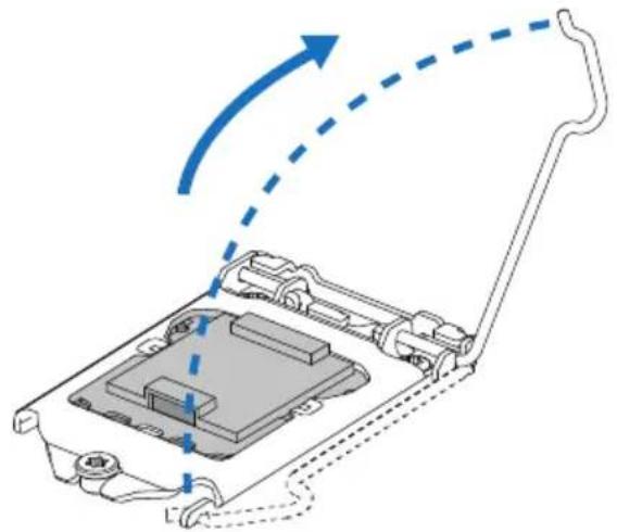
natural_image
Diagram of a mechanical device with internal components and directional arrows indicating motion (no text or symbols)步骤3: 取掉针脚保护盖
natural_image
Diagram of a mechanical device with an upward arrow indicating motion, showing internal components and a handle (no text or symbols)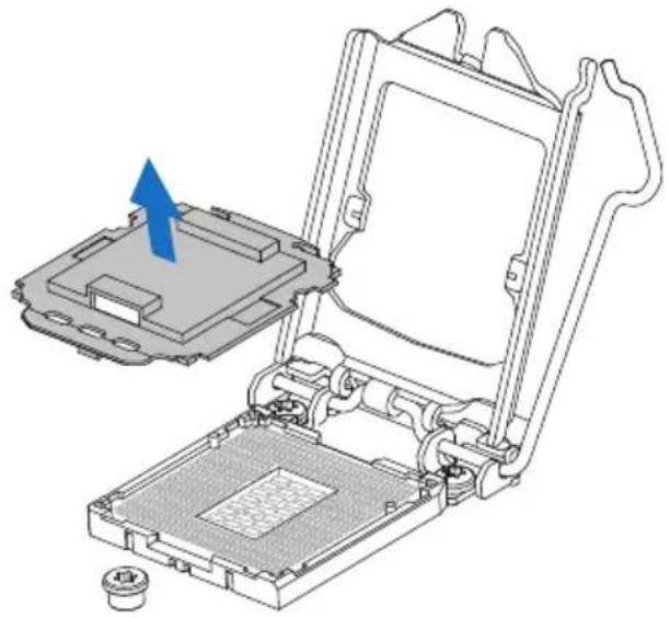
natural_image
Technical diagram of a mechanical assembly with a blue arrow indicating a component, no visible text or symbols步骤5: 固定CPU,将拉杆闭合。
注意
| 针 | 定义 |
| 1 | 接地 |
| 2+12V | |
| 3FAN RPM rate sense | |
| 4 Smart Fan Control (By Fan) | |
SYS_FAN1/2: 系统风扇接头
| 针 | 定义 |
| 1 | 接地 |
| 2+ | 12V |
| 3FAN RPM rate sense | |
| 4 Smart Fan Control (By Fan) | |
注意
natural_image
Technical line drawing of a RAM module with scroll wheel and directional arrows indicating rotation (no text or symbols)natural_image
Technical line drawing of a mechanical component with directional arrows indicating motion (no text or symbols)注意
| 双通道状态 DIMMA1 | DIMMA2 DIM | MMB1 DIM | MB2 | |
| Enabled O X | O X | |||
| Enabled X | O X | O | ||
| Enabled O O O O |
| 针定义针定义 | ||
| 13+3.3V 1 +3.3V | ||
| 14-12V 2 +3.3V | ||
| 15接地3接地 | ||
| 16 PS_ON 4 +5V | ||
| 17接地5接地 | ||
| 18接地6 +5V | ||
| 19接地7接地 | ||
| 20 NC 8 PW_OK | ||
| 21+5V 9唤醒电压 | +5V | |
| 22+5V 10 +12V | ||
| 23+5V 11 +12V | ||
| 24接地12 +3.3V |
ATXPWR2: ATX电源接口
| 针定义针定义 | ||
| 1 VBUS0 11 D2+ | ||
| 2 SSRX1- 12 D2- | ||
| 3SSRX1+ 13 接地 | ||
| 4接地 14 SSTX2+ | ||
| 5 SSTX1- 15 SSTX2- | ||
| 6 SSTX1+ 16 接地 | ||
| 7接地 17 SSRX2+ | ||
| 8 D1- 18 SSRX2- | ||
| 9 D1+ 19 VBUS1 | ||
| 10 ID 20 Key |
| HD Audio AC' 97 | |||
| 针定义针定义 | |||
| 1 Mic Left in 1 Mic In | |||
| 2接地2接地 | |||
| 3Mic Right in 3Mic Power | |||
| 4 GPIO 4 Audio Power | |||
| 5 Right line in 5 RT Line Out | |||
| 6 Jack Sense 6 RT Line Out | |||
| 7Front Sense 7Reserved | |||
| 8 Key 8 Key | |||
| 9 Left line in 9 LFT Line Out | |||
| 10 Jack Sense 10 LFT Line Out | |||
注意
| 针 | 定义 |
| 1 VCC12 | |
| 2 LED_GREEN | |
| 3LED_RED | |
| 4 LED_BLUE | |
ECO模式:
3.3 软件
安装软件
请参照以下步骤来更新开机画面:
注意
RAID 5
parity across disks
flowchart
graph TD
    A["DATA1"] --> B["Data 1"]
    C["DATA3"] --> D["Data 1"]
    E["PARITY"] --> F["Data 1"]
    G["DATA7"] --> H["Data 1"]
    I["DATA9"] --> J["Data 1"]
    K["PARITY"] --> L["Data 1"]
    B --> M["Data 2"]
    D --> N["Data 2"]
    F --> O["Data 2"]
    H --> P["Data 2"]
    J --> Q["Data 2"]
    L --> R["Data 2"]
    N --> S["Data 2"]
    O --> T["Data 2"]
    P --> U["Data 2"]
    Q --> V["Data 2"]
    R --> W["Data 2"]
    S --> X["Data 2"]
    T --> Y["Data 2"]
    U --> Z["Data 2"]
    V --> AA["Data 2"]
    W --> AB["Data 2"]
    X --> AC["Data 2"]
    Y --> AD["Data 2"]
    Z --> AE["Data 2"]
- FCC Information and Copyright
- Table Of Contents
- FCC Information and Copyright 1
- Chapter 1: Introduction....3
- Chapter 2: Hardware installation....7
- Chapter 3: UEFI BIOS & Software....19
- Chapter 4: Useful help....31
- APPENDIX I: Specifications in Other Languages 37
- Chapter 1: Introduction
- Before You Start
- Package Checklist
- Note
- Rear Panel Connectors
- Chapter 2: Hardware installation
- Install Central Processing Unit (CPU)
- Install a Heatsink
- Connect Cooling Fans
- Install System Memory
- Memory Capacity
- Dual Channel Memory Installation
- Expansion Slots
- PCI1/PCI2/PCI3: Peripheral Component Interconnect Slots
- PEX16\_1: PCI-Express Gen3 x16 Slot (x16 speed)
- PEX16\_2: PCI-Express Gen3 x16 Slot (x4 speed)
- PEX1\_1: PCI-Express Gen3 x1 Slot
- Install an Expansion Card
- Jumper & Switch Setting
- JCMOS1: Clear CMOS Jumper
- Clear CMOS Procedures:
- BIOS\_SW1: Dual BIOS Switch
- Headers & Connectors
- ATXPWR1: ATX Power Source Connector
- ATXPWR2: ATX Power Source Connector
- PANEL1: Front Panel Header
- SATA\_Express\_1: SATA Express Connector
- SATA3\_3/3\_4: Serial ATA Connectors
- JFRONT\_USB3\_1: Header for USB 3.0 Ports at Front Panel
- F\_USB1/2: Header for USB 2.0 Ports at Front Panel
- JSPDIFOUT1: Digital Audio-out Connector
- F\_AUDIO1: Front Panel Audio Header
- 5050\_RGBLED1: RGB LED Strip (5050 SMD) Header
- Buttons & LEDs
- ECO Mode:
- Sport Mode:
- Reset:
- Power:
- LEDs
- Chapter 3: UEFI BIOS & Software
- UEFI BIOS Setup
- BIOS Update
- BIOSTAR BIOS Flasher
- BIOS Update Utility (through the Internet)
- BIOS Update Utility (through a BIOS file)
- Backup BIOS
- Software
- Installing Software
- Launching Software
- BIOScreen Utility
- eHot-Line
- RACING GT
- System Information
- SmartEAR
- Requirements:
- Installation Guide:
- Vivid LED DJ
- H/W Monitor
- OC/OV
- Chapter 4: Useful help
- Driver Installation
- Driver Installation
- Software Installation
- Manual
- AMI BIOS Beep Code
- Troubleshooting
- CPU Overheated
- RAID Functions
- RAID Definitions
- Features and Benefits
- APPENDIX I: Specifications in Other Languages
- FCC条款
- 注意
- ATXPWR2: ATX电源接口
- ECO模式:
- 软件
- 安装软件
Brand : BIOSTAR
Model : B150GT5
Category : Uncategorized