
GV-Joystick V2 - Manette de contrôle Geovision - Free user manual and instructions
Find the device manual for free GV-Joystick V2 Geovision in PDF.


| Product Type | PTZ Joystick Controller |
| Brand | Geovision |
| Model | GV-Joystick V2 |
| Dimensions (W x H x D) | 160 x 90 x 118 mm / 6.3 x 3.54 x 4.65 in |
| Weight | 500 g / 1.1 lb |
| Power Supply | DC 5V, 50mA (via USB bus power) |
| Communication Interface | USB 2.0 (to PC), RJ-45 (to GV-Keyboard V3) |
| Operating System Support | Windows 7/8/10, Server 2008/2012/2016/2019 (32/64-bit) |
| PTZ Control Functions | Pan, Tilt, Zoom, Focus (via handle and F1/F3 keys) |
| Function Keys | F1 (Focus In), F2 (Previous Camera), F3 (Focus Out), F4 (Next Camera), F5 (Auto Focus), F6 (Home) – customizable |
| Power LED Indicator | Indicates power activity; blinks red during calibration |
| Calibration Method | Press and hold F1+F2+F3+F4 for 3 seconds until LED blinks red, then release |
| Maximum Units Connected | Up to 8 GV-Joystick V2 |
| Camera Control | Supports multiple PTZ cameras; switch via Previous/Next Camera buttons |
| Compatibility | Works with GV-Software (GV-DVR/NVR/VMS) and GV-Keyboard V3 |
| Packing List | GV-Joystick V2, USB Type A to Type B cable |
| Environmental - Operating Temperature | 0°C ~ 50°C / 32°F ~ 122°F |
| Environmental - Humidity | 5% ~ 95% (non-condensing) |
| Certifications | FCC Class A, CE, RoHS, WEEE |
| Maintenance & Cleaning | Wipe with a dry, soft cloth; do not use liquids or abrasives |
| Spare Parts & Repairability | No user-serviceable parts; contact Geovision support for repairs |
Frequently Asked Questions - GV-Joystick V2 Geovision
User questions about GV-Joystick V2 Geovision
0 question about this device. Answer the ones you know or ask your own.
Ask a new question about this device
Download the instructions for your Manette de contrôle in PDF format for free! Find your manual GV-Joystick V2 - Geovision and take your electronic device back in hand. On this page are published all the documents necessary for the use of your device. GV-Joystick V2 by Geovision.
USER MANUAL GV-Joystick V2 Geovision
natural_image
Exterior view of a GeoVision remote control device with labeled buttons (F1–F5) against a blue background with directional arrows (no text beyond labels)
GeoVision Inc
© 2021 GeoVision, Inc. All rights reserved.
Under the copyright laws, this manual may not be copied, in whole or in part, without the written consent of GeoVision.
Every effort has been made to ensure that the information in this manual is accurate. GeoVision, Inc. makes no expressed or implied warranty of any kind and assumes no responsibility for errors or omissions. No liability is assumed for incidental or consequential damages arising from the use of the information or products contained herein.
GeoVision, Inc.
9F, No. 246, Sec. 1, Neihu Rd.,
Neihu District, Taipei, Taiwan
Trademarks used in this manual: GeoVision, the GeoVision logo and GV series products are trademarks of GeoVision, Inc. Windows and Windows XP are registered trademarks of Microsoft Corporation.
September 2021
Contents
Regulatory Notices......i
1. Introduction......1
1.1 Packing List .... 1
1.2 System Requirements.... 1
2. Overview ...... 2
2.1 Front View.... 2
2.2 Rear View 3
3. Installation 4
3.1 Connecting to GV-Software.... 4
3.2 Connecting to GV-Keyboard V3 4
4. Starting GV-Joystick....5
5. Controlling Multiple PTZ Cameras in GV-System 8
6. Calibrating GV-Joystick V2 9
7. Specifications ...... 10
Regulatory Notices

FCC Notice
This equipment has been tested and found to comply with the limits for a Class A digital device, pursuant to part 15 of the FCC Rules. These limits are designed to provide reasonable protection against harmful interference when the equipment is operated in a commercial environment.
Class A
This equipment generates, uses, and can radiate radio frequency energy and, if not installed and used in accordance with the instruction manual, may cause harmful interference to radio communications. Operation of this equipment in a residential area is likely to cause harmful interference in which case the user will be required to correct the interference at their own expense.

CE Notice
This is a Class A product. In a domestic environment, this product may cause radio interference in which case the user may be required to take adequate measures.
RoHS
RoHS Compliance
The Restriction of Hazardous Substances (RoHS) Directive is to forbid the use of hazardous materials of production. To meet the RoHS Directive requirements, this product is made to be RoHS compliant.

WEEE Compliance
This product is subject to the Waste Electrical and Electronic Equipment (WEEE) Directive and made compliant with the WEEE requirements.
1. Introduction
GV-Joystick V2 is a plug-and-play device, used to pan, tilt, zoom and focus a PTZ camera. It works with GeoVision software and hardware independently, and its compatibility with GV-Keyboard V3 empowers the operation of GV-System as well.
1.1 Packing List
- GV-Joystick V2
- USB Type A to Type B Cable
1.2 System Requirements
| OS | 32-bit | Windows 7 / 8 / 10 / Server 2008 |
| 64-bit | Windows 7 / 8 / 10 / Server 2008 R2 / Server 2012 / Server 2016 / Server 2019 |
Note:
- For the users of Windows 10 update version 1809 or later, you need to update GV-Joystick V2's driver manually. For details, see the technical post.
- The joystick is a HID device compatible with any third-party software supported HID protocol.
2. Overview
2.1 Front View

| No | Name Function | |
| 1 | Power LED Indicates power activity. | |
| 2 | F1 (Focus In) Adjusts focus near. | |
| 3 | F3 (Focus Out) Adjusts focus far. | |
| 4 | F5 (Auto Focus) Automatically focus a camera. | |
| 5 | F2 (Previous Camera) | Controls the previous camera. |
| 6 | F4 (Next Camera) | Controls the next camera. |
| 7 | F6 (Home) Brings the camera to a home position. | |
| 8 | Handle | Use the handle to have the following movements:● Push right / left to pan a camera right / left.● Push up / download to tile a camera up / download.● Turn the handle right to zoom in.● Turn the handle left to zoom out. |
Note:
- F1 \~ F6 keys described here are defaults. You can customize the functions using the Keyboard & Joystick controller.
- For GV-Joystick V2 connected to GV-Keyboard V3, the keys can not be customized, and the F5 and F6 keys are not functional.
2.2 Rear View

| No | Name Function | |
| 1 | USB to DVR port Connects to computer | |
| 2 | To GV-Keyboard port Connects to GV-Keyboard V3 |
3. Installation
There are two ways to connect GV-Joystick V2 to GV-Software:
- Direct connection using the USB to DVR port
- Indirect connection through GV-Keyboard V3 using the To GV-Keyboard port
Note:
- These two ports cannot be used simultaneously.
- For connecting GV-Joystick V2 to GV-Center V2, only the direct connection is supported.
3.1 Connecting to GV-Software
GV-Joystick V2 is a plug-and-play device that works with GV-Software directly. To connect GV-Joystick V2 to GV-Software, use the supplied USB cable.
3.2 Connecting to GV-Keyboard V3
To connect GV-Joystick V2 to GV-Keyboard V3, use the supplied RJ-45 cable.
4. Starting GV-Joystick
When using GV-Joystick V2 to control PTZ cameras connected to GV-Software, it is required to run GV-Mcamctrl Utility in the background. Up to 8 units of GV-Joystick V2 can be connected together, but only one GV-Joystick V2 can control one PTZ camera at one time.
Note: For combining use with GV-Keyboard V3, see GV-Keyboard V3 User's Manual.
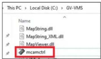
- Run mcamctrl.exe from the GV-Software folder.
- The Keyboard & Joystick controller appears.
![Keyboard & Joystick GVKB1 F1 F2 F3 F4 F5 F6 F7 F8 DVR ID 1 Name: Startup type: Manual PTZ Maximum Speed: Monopoly mode: Joystick Control: Setting Setting Device 1: GeoVision Joystick [70] Device 2: Device 3: Device 4: Device 5: Device 6: Device 7: Device 8: Refresh Keyboard & Joystick](/content/2026/05/912861/images/069c1a8b53bf1f1c795fe298e164e102c1d78779577b857845f414fd710d2c9f.jpg)
- Select GeoVision Joystick from the Device drop-down list.
Tip: If you can not find the GeoVision Joystick option, make sure your GV-Joystick is properly connected and then click the Refresh button from the Keyboard & Joystick controller to scan for the device again.

GeoVision™
- Select the ID of the joystick and name it.
- In Startup Type, select Manual or Automatic to run the Keyboard & Joystick controller manually or automatically at next startup.
- To adjust the camera speed, use the PTZ Maximum Speed slider.
- To customize the function keys:
A. Click the Setting button next to Joystick Control. This dialog box appears.
![Keyboard & Joystick GV-K8 1 F1 F2 F3 F4 F5 F6 F7 F8 DVR ID 1 Name: Startup type: Manual PTZ Maximum Speed: + Monopoly mode: Joystick Control: Setting Joystick Control Button List F1 Focus In Focus Out Previous Camera Next Camera Home Auto Focus Iris In Iris Out Auto Iris OK Cancel Device 1: GeoVision Joystick [70] Device 2: Device 3: Device 4: Device 5: Device 6: Device 7: Device 8: Refresh Keyboard & Joystick](/content/2026/05/912861/images/7645663f8e906b446ccbb7d544effbd38ab9bb654c5d82390228f911ac1642ae.jpg)
B. Select a function key (F1 \~ F6) and select a function.
- To add another GV-Joystick V2, repeat step 3 and select GeoVision Joystick with a different serial number from the Device drop-down list.
- Click the Start Service button ▶ to start the service. If you want to stop the service, click the Stop Service button ■.
Note:
- If you add or remove a GV-Joystick V2, the corresponding COM port in Windows may change. In this case, click the Refresh button and check the GV-Joystick V2 assigned in the Device drop-down list.
- The serial number is randomly generated by Windows and may change if GV-Joystick V2 is re-installed.
- The buttons F1 to F8 and Print on the toolbar of Keyboard & Joystick controller are only available when GV-Keyboard V3 is in use.
- To add a PTZ camera to GV-DVR / NVR / VMS, click the Configure button > General Setting > System Configure > PTZ Device Setup to enable the settings. For details, see PTZ Control in GV-DVR / NVR User's Manual or GV-VMS User's Manual.
5. Controlling Multiple PTZ Cameras in GV-System
GV-Joystick V2 allows you to control more than one PTZ camera at a time. For this, you need to assign PTZ cameras to camera channels in GV-DVR / NVR / VMS first.
- Click the Configure button > Accessories > PTZ Device > Camera Mapping PTZ Dome. This dialog box appears.
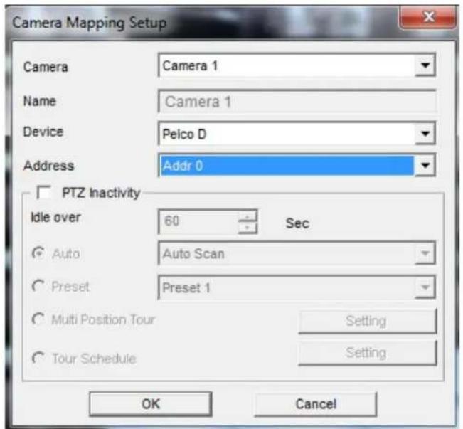
- Select a Camera channel.
- Select the PTZ model connected to the selected channel from the Device drop-down list..
- When more than one identical PTZ brands are connected to the system, use the Address drop-down list to choose the corresponding address.
- Click OK to apply the settings.
- To control multiple cameras using GV-Joystick V2, click the Previous Camera and Next Camera buttons on the joystick.
6. Calibrating GV-Joystick V2
The internal settings may deviate and the control can become less accurate after a period of time. Follow the steps below to calibrate your GV-Joystick V2.
- Press and hold the F1, F2, F3 and F4 buttons on the GV-Joystick for 3 seconds. The Power LED blinks red.
- Release the buttons. The Power LED turns green and the settings are calibrated.

natural_image
Front view of a GeoVision device with labeled buttons (F1–F6) and a central circular dial (no readable text beyond branding)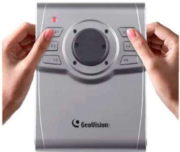
natural_image
Close-up of hands holding a GeoVision device with labeled buttons (F1–F6) and a red indicator light, no readable text or symbols beyond branding.7. Specifications
| OS Supported | 32-bit | Windows XP / Vista / 7 / 8 / Server 2008 |
| 64-bit | Windows 7 / 8 / Server 2008 R2 / Server 2012 | |
| Communication | USB 2.0 | Connects to PC |
| RJ-45 | Connects to GV-Keyboard V3 | |
| Power DC IN | DC 5V 50mA | |
| Environmental Conditions | Operating Temperature | 0°C ~ 50°C / 32°F ~ 122°F |
| Humidity | 5%~95% (non-condensing) | |
| Dimensions (W X H X D) | 160 x 90 x 118 mm / 6.3 x 3.54 x 4.65 in | |
| Weight | 500 g / 1.1 lb | |
All specifications are subject to change without notice.
- GeoVision Inc
- © 2021 GeoVision, Inc. All rights reserved.
- Contents
- Regulatory Notices......i
- Introduction......1
- Overview ...... 2
- Installation 4
- Starting GV-Joystick....5
- Controlling Multiple PTZ Cameras in GV-System 8
- Calibrating GV-Joystick V2 9
- Specifications ...... 10
- Regulatory Notices
- FCC Notice
- Class A
- CE Notice
- RoHS
- RoHS Compliance
- WEEE Compliance
- Introduction
- Packing List
- System Requirements
- Note:
- Overview
- Front View
- Rear View
- Installation
- Connecting to GV-Software
- Connecting to GV-Keyboard V3
- Starting GV-Joystick
- GeoVision™
- Controlling Multiple PTZ Cameras in GV-System
- Calibrating GV-Joystick V2
- Specifications
Brand : Geovision
Model : GV-Joystick V2
Category : Manette de contrôle