SUB 808-AS - Subwoofer RCF - Free user manual and instructions
Find the device manual for free SUB 808-AS RCF in PDF.


| Product Type | Professional Active Subwoofer |
| Brand | RCF |
| Model | SUB 808-AS |
| Frequency Response | 40 Hz - 400 Hz |
| Maximum SPL | 129 dB @ 1m |
| Woofer | 2 x 8" neo, 2.5" voice coil |
| Amplifier Power | 2000 W Peak |
| Cooling | Convection |
| Input Connectors | XLR (balanced/unbalanced), RDNet Ethercon |
| Output Connectors | XLR (loop through), RDNet Ethercon |
| Controls | Volume knob, preset buttons (LP 90 Hz/KX 515-A, Bypass/Local Setup), RDNet software |
| Cabinet Material | Baltic birch plywood |
| Color | Black (polyurea coating) |
| Dimensions (H x W x D) | 243.5 x 603.5 x 430 mm |
| Weight | 20 kg (44.09 lbs) |
| Hardware | 2x M20 threaded pole mounts, 8x M10 flying points, side handle |
| Grille | Steel |
| Power Connection | PowerCON TRUE1 TOP (input and link) |
| Voltage | 100-120V~ / 200-240V~ (switchable by service center) |
| Protection | Complete system with limiter, excursion protection |
| RDNet Compatibility | Yes, for monitoring and control |
| Cardioid Configuration | Supported via RDNet presets |
| Suspension | Yes, with optional brackets (up to 2 units) |
| Pole Mount | Yes, for satellite speakers (e.g., KX 515-A) |
Frequently Asked Questions - SUB 808-AS RCF
User questions about SUB 808-AS RCF
0 question about this device. Answer the ones you know or ask your own.
Ask a new question about this device
Download the instructions for your Subwoofer in PDF format for free! Find your manual SUB 808-AS - RCF and take your electronic device back in hand. On this page are published all the documents necessary for the use of your device. SUB 808-AS by RCF.
USER MANUAL SUB 808-AS RCF
DIMENSIONS / DIMENSIONI 28
SPECIFICATIONS/SPECIFICHE 29
1. SAFETY PRECAUTIONS AND GENERAL INFORMATION
The symbols used in this document give notice of important operating instructions and warnings which must be strictly followed.
 | CAUTION | Important operating instructions: explains hazards that could damage a product, including data loss |
 | WARNING | Important advice concerning the use of dangerous voltages and the potential risk of electric shock, personal injury or death. |
 | IMPORTANT NOTES | Helpful and relevant information about the topic |
 | SUPPORTS, TROLLEYS AND CARTS | Information about the use of supports, trolleys and carts. Reminds to move with extreme caution and never tilt. |
| [TWXA] | WASTE DISPOSAL | This symbol indicates that this product should not be disposed with your household waste, according to the WEEE directive (2012/19/EU) and your national law. |

IMPORTANT
This manual contains important information about the correct and safe use of the device. Before connecting and using this product, please read this instruction manual carefully and keep it on hand for future reference. The manual is to be considered an integral part of this product and must accompany it when it changes ownership as a reference for correct installation and use as well as for the safety precautions. The company will not assume any responsibility for the incorrect installation and / or use of this product.
All the precautions, in particular the safety ones, must be read with special attention, as they provide important information.
SAFETY PRECAUTIONS
GENERAL SAFETY PRECAUTIONS
- Protect loudspeaker AC and signal lines from damage. Make sure they are positioned in a way that they cannot be stepped on or crushed by objects.
- To prevent the risk of electric shock, never open this product: there are no parts inside that the user needs to access. Never attempt to carry out any operations, modifications or repairs that are not expressly described in this manual.
- If this product begins emitting any strange odours or smoke, in case of an active speaker immediately switch it off and disconnect the power cable; in case of a passive speaker switch the amplifier off and remove it from the line.
-
Contact your authorized service centre or qualified personnel if any of the following occur:
-
The device does not function (or works in an anomalous way).
- The cable has been damaged.
- Objects or liquids are inside the loudspeaker.
-
The loudspeaker has been damaged due to heavy impacts or fire.
-
Make sure that no objects or liquids can get into this product, as this may cause a short circuit. This apparatus shall not be exposed to dripping or splashing. No objects filled with liquid, such as vases, shall be placed on this apparatus. No naked sources (such as lighted candles) should be placed on this apparatus.
-
Do not connect this product to any equipment or accessories not foreseen. For suspended installation, only use the dedicated anchoring points and do not try to hang this product by using elements that are unsuitable or not specific for this purpose. Also check the suitability of the support surface to which the product is anchored (wall, ceiling, structure, etc.), and the components used for attachment (screw anchors, screws, brackets not supplied by RCF etc.), which must guarantee the security of the system / installation over time, also considering, for example, the mechanical vibrations normally generated by transducers. To prevent the risk of falling equipment, do not stack multiple units of this product unless this possibility is specified in the user manual.
-
The company strongly recommends to install this product only by professional qualified installers (or specialised firms) who can ensure correct installation and certify it according to the regulations in force. The entire audio system must comply with the current standards and regulations regarding electrical systems.
-
Supports, trolleys and carts: The equipment should be only used on supports, trolleys and carts, where necessary, that are recommended by the manufacturer. The equipment / support / trolley / cart assembly must be moved with extreme caution. Sudden stops, excessive pushing force and uneven floors may cause the assembly to overturn. Never tilt the assembly.
-
Hearing loss: Exposure to high sound levels can cause permanent hearing loss. The acoustic pressure level that leads to hearing loss is different from person to person and depends on the duration of exposure. To prevent potentially dangerous exposure to high levels of acoustic pressure, anyone who is exposed to these levels should use adequate protection devices. When a transducer capable of producing high sound levels is being used, it is necessary to wear ear plugs or protective earphones. See the technical specifications in the instruction manual for the maximum sound pressure the loudspeaker can produce.
ACTIVE DEVICES: ACTIVE SPEAKERS and AMPLIFIERS
- The mains voltage is sufficiently high to involve a risk of electrocution; install and connect this product before plugging it in.
- Before powering up, make sure that all the connections have been made correctly and the voltage of your mains corresponds to the voltage shown on the rating plate on the unit, if not, please contact your dealer.
- The metallic parts of the unit are earthed through the power cable. An apparatus with CLASS I construction shall be connected to a mains socket outlet with a protective earthing connection by a 3-pole power cord.
-
Protect the power cable from damage; make sure it is positioned in a way that it cannot be stepped on or crushed by objects.
-
If the product is not used for a long period, disconnect the power cable.
-
Ensure that no children have access to the installation materials and components.
-
Before powering up, make sure that all the connections have been made correctly and the voltage of your mains corresponds to the voltage shown on the rating plate on the unit. If not, please contact your dealer.
-
Always make sure the power cord and and all plug assemblies are certified and suitable for the use in the particular countries where the product shall be installed.
-
Use the mains plug to disconnect the apparatus from the mains.
-
If the device is provided with internal fuse or if it requires operations, contact your authorized service centre or qualified personnel as defined in the IEC 62368-1 3rd Ed. Interfaces at ES3 level present.
-
If the device is provided with power socket with accessible fuse holder, or accessible independent fuse holder, disconnect mains cable device before fuse replacement. The fuse on the AC mains input may be on the neutral, the AC mains shall be disconnected to de-energize the phase.
PASSIVE DEVICES and ACCESSORIES
- Loudspeaker lines (amplifier outputs) can have a sufficiently high voltage to involve a risk of electrocution: never install or connect this loudspeaker when amplifiers are switched on.
- Make sure all connections have been made correctly and the loudspeaker input impedance is suitable for the amplifier output.
- To ensure a correct sound reproduction, loudspeaker phase is to be respected (loudspeakers are connected respecting the amplifier polarity). This is important when loudspeakers are installed adjacent one another, for instance, in the same room.
- To prevent inductive effects from causing hum, noise and a bad system working, loudspeaker lines should not be laid together with other electric cables (mains), microphone or line level signal cables connected to amplifier inputs.
- The loudspeaker cable shall have wires (twisted, if possible, to reduce inductive effects due to surrounding electro-magnetic fields) with a suitable section and a sufficient electrical insulation. Refer to local regulations since there may be additional requirements about cable characteristics.
- Do NOT connect loudspeaker low impedance (8 - 4 Ω) inputs to 100 / 70 V constant voltage lines.
1. SAFETY PRECAUTIONS AND GENERAL INFORMATION
SUSPENDED DEVICES
- Suspending any object is a potentially dangerous operation and should only be attempted by individuals who have a thorough knowledge of the techniques and regulations of rigging objects overhead.
- The company strongly recommends that all devices should be suspended taking into account all current national, federal, state and local regulations. It is the responsibility of the installer to ensure that all devices are safely installed in accordance with all such regulations.
- The company strongly recommends to inspect the system at least once a year. If any sign of weakness or damage is detected remedial actions should be taken immediately.
- The user is responsible for making sure that the supporting surfaces and any additional hardware used is capable of supporting the system. Any hardware used to suspend a loudspeaker array that is not provided by or associated with the company is not recommended and is under the responsibility of others.
OPERATING PRECAUTIONS
- Install the product in accordance with manufacturer's instructions.
- Mechanical and electrical factors need to be considered when installing a professional audio system (in addition to those which are strictly acoustic, such as sound pressure, angles of coverage, frequency response, etc.).
- If the product needs to be used in a cold environment, slowly warm up the voice coils by sending a low-level signal for about 15 minutes before sending high-power signals.
- Place this product far from any heat sources and always ensure an adequate air circulation around it.
- Do not overload this product with too much power or for a long time.
- Never force the control elements (keys, knobs, etc.).

IMPORTANT
To prevent the occurrence of noise on line signal cables, use screened cables only and avoid putting them close to:
- Equipment that produces high-intensity electromagnetic fields
- Power cables
- Loudspeaker lines


WARNING! CAUTION! To prevent the risk of fire or electric
shock, never expose this product to rain or humidity.

WARNING! To avoid the risk of electric shock, do not connect to the mains supply if the device is open or, in the case of speakers, while the grille is removed.

WARNING! To reduce the risk of electric shock, do not disassemble this product unless you are qualified. Refer servicing to qualified service personnel.
CORRECT DISPOSAL OF THIS PRODUCT

This product should be handed over to an authorized collection site for recycling waste electrical and electronic equipment (EEE). Improper handling of this type of waste could have a possible negative impact on the environment and human health due to potentially hazardous substances that are generally associated with EEE. At the same time, your cooperation in the correct disposal of this product will contribute to the effective usage of natural resources. For more information about where you can drop off your waste equipment for recycling, please contact your local city office, waste authority or your household waste disposal service.
CARE AND MAINTENANCE
To ensure a long-life service, this product should be used following these advices:
- If the product is intended to be set up outdoors, be sure it is under cover and protected to rain and moisture.
- In the case of fixed installations, it is recommended to schedule periodic checks of the entire system and all its parts for the entire duration of the installation.
- All personnel involved in the installation must be adequately trained and educated on safety procedures and equipped with appropriate personal protective equipment (PPE).
- If it is necessary to replace a part, always contact authorized centers only or use only parts supplied by RCF.
- RCF is not responsible for problems or malfunctions encountered in the case of replacements of parts or modifications to the system initiated by the user.
- Do not use abrasives, cleaning solvents, alcohol, benzene or other volatile substances for cleaning the external parts of this product. Always use a dry cloth to clean the exterior surfaces of the speaker and always do it when the power is turned off.


WARNING! CAUTION! For powered devices, clean only
when the power is turned off.
RCF S.p.A. reserves the right to make changes without prior notice to rectify any errors and / or omissions.
Always refer to the latest version of the manual on www.rcf.it.
2. DESCRIPTION
SUB 808-AS - PROFESSIONAL ACTIVE SUBWOOFER
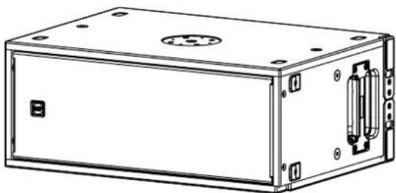
SUB 808-AS is a compact low-profile high-performance active subwoofer. It features two vented-loaded 8" cone woofers powered by a 2000 Watts two-channel amplifier (one for each woofer) on a baltic birch plywood cabinet painted with black or white polyurea.
Management and tuning are available via RDNet software or using the two preset buttons accessible from the back panel. The cabinet features rubber feet on two sides and two threaded pole-mounts for horizontal and vertical placement. Two stabilizing brackets make the vertical placement stable and firm.
SUB 808-AS can be used stand-alone, in subwoofer arrays, or as the low-frequency complement for KX 515-A speaker.
natural_image
Technical line drawing of a rectangular electronic enclosure with mounting holes and internal components (no text or symbols)SUB 808-AS
2000 Watt 2 X 8" Vented Woofers 19,5 Kg (43 lbs)
3. REAR PANEL FEATURES AND CONTROLS
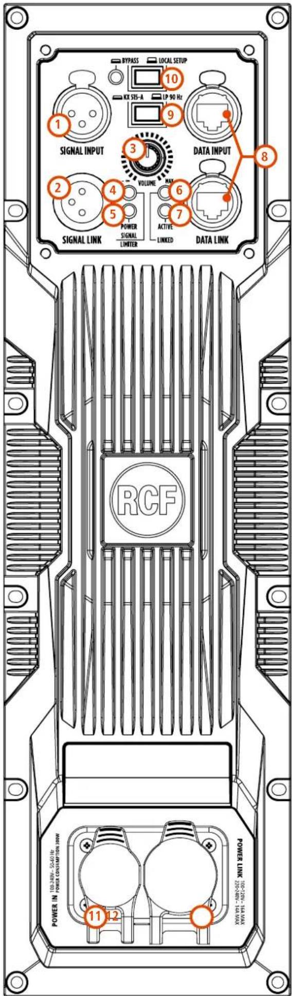
① FEMALE XLR INPUTS (BAL/UNBAL) The system accepts XLR input connectors.
② MALE XLR SIGNAL OUTPUT The output XLR connector provides a loop through for speakers daisy chaining. The balanced connector is connected in parallel and can be used to send the audio signal to other amplified speakers, recorders or supplementary amplifiers.
③ SYSTEM VOLUME KNOB
4 SIGNAL / LIMITER LED The LED light is green when a signal is applied to the speaker. It turns RED when the speaker limiter activates.
5 POWER LED This green led is ON when the speaker is connected to the main power supply.
6 LINK LED This LED turns on when the speaker is connected to RDNet.
7 ACTIVE LED This LED blinks when the speaker is transmitting data over RDNet.
8 RDNET DATA INPUT AND DATA LINK The RDNET IN/OUT PLUG SECTION features etherCON connectors for the RCF RDNet protocol. This allows the user to completely control the speaker using the RDNet software.
9 LP 90 Hz / KX 515-A When this button is released the subwoofer works with its standard subwoofer configuration (40 Hz - 90 Hz). When this button is pressed the subwoofer automatically sets its alignment with RCF KX 515-A; at the same time the button "FLAT / HIGH PASS" on KX 515-A has to be pressed (on "HIGH PASS" mode).
10 BYPASS / LOCAL SETUP When pressed, the setup is loaded from the internal memory that only RDNet can write. Every time the speaker is turned on, the last stored configuration is applied.
When the button is released, the speaker uses its local setup and will not remember its last RDNet setup when turned on again.
11 AC POWER INPUT PowerCON TRUE1 TOP IP-Rated power connection.
12 AC OUTPUT LINK Sends the AC power to another speaker.
Power link: 100-120V\~16 A MAX | 200-240V\~14 A MAX.
WAF
WARNING! CAUTION! Loudspeaker connections should be only made by qualified and experienced personnel having the technical know-how or enough specific instructions (to ensure that connections are made correctly) in order to prevent any electrical danger.
To prevent any risk of electric shock, do not connect loudspeakers when the amplifier is switched on.
Before turning the system on, check all connections and make sure there are no accidental short circuits.
The entire sound system shall be designed and installed in compliance with the current local laws and regulations regarding electrical systems.
4. CONNECTIONS
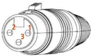
The connectors must be wired according to the standards specified by the AES (Audio Engineering Society).
MALE XLR CONNECTOR
Balanced wiring
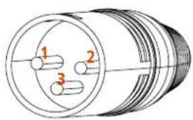
FEMALE XLR CONNECTOR
Balanced wiring
natural_image
Technical line drawing of a cylindrical mechanical component with three labeled ports (no text or symbols present)PIN 1 = GROUND (SHIELD)
PIN 2 = HOT (+)
PIN 3 = COLD (-)
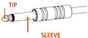
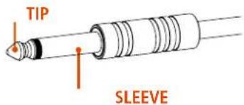
TS CONNECTOR
Unbalanced mono wiring
TRS CONNECTOR
Balanced mono wiring
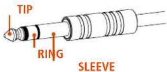
SLEEVE = GROUND (SHIELD)
TIP = HOT (+)
RING = COLD (-)
On the rear panel you will find all the controls, signal and power inputs. At first verify the voltage label applied to the rear panel (115 Volt or 230 Volt). The label indicates the right voltage. If you read a wrong voltage on the label or if you can't find the label at all, please call your vendor or authorized RCF SERVICE CENTRE before connecting the speaker. This fast check will avoid any damage.
In case of need of changing the voltage please call your vendor or authorized RCF SERVICE CENTRE. This operation requires the replacement of the fuse value and is reserved to an RCF SERVICE CENTRE.
You can now connect the power supply cable and the signal cable. Before turning on the speaker make sure the volume control is at the minimum level (even on the mixer output). It is important that the mixer is already ON before turning on the speaker. This will avoid damages to the speaker and noisy "bumps" due to turning on parts on the audio chain. It is a good practice to always turn on the speakers at last and turning them off immediately after their use. You can now turn ON the speaker and adjust the volume control to a proper level.
PROTECTIONS
The speaker is equipped with a complete system of protection circuits. The circuit is acting very gently on audio signal, controlling level and maintaining distortion at acceptable level.
VOLTAGE SETUP (RESERVED TO THE RCF SERVICE CENTRE)
200-240 Volt, 50 Hz SETUP:
FUSE VALUE T 3.15 A L 250V
100-120 Volt, 60 Hz SETUP:
FUSE VALUE T6.3 A L 250V
5. INSTALLATION
The Subowoofer RCF SUB 808-AS can be used either in horizontal or vertical position.
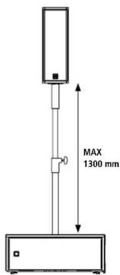
HORIZONTAL CONFIGURATION (setup with RCF KX 515-A)
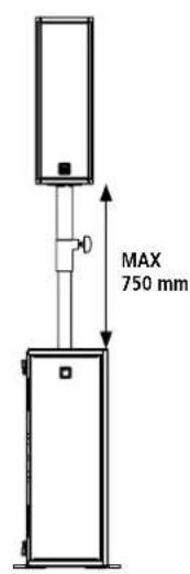
VERTICAL CONFIGURATION (setup with RCF KX 515-A)
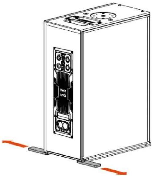
natural_image
Technical line drawing of a server rack unit with mounting base and internal circuit panel (no text or symbols)When used on vertical position, slide the two plastic plates on the bottom of the speaker for a better stability and safety.

CAUTION! When pole mounting a KX 515-A over SUB 808-AS, the maximum pole length must be 1300mm (for the horizontal configuration) and 750mm (for the vertical configuration).

When SUB 808-AS is used together with KX 515-A remember to press both the following buttons:
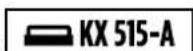
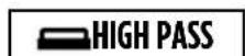
on SUB 808-AS on KX 515-A
FLYING POINTS
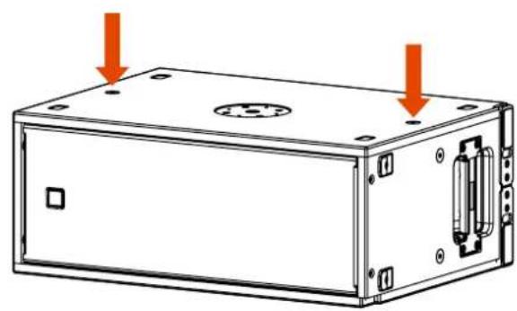
SUB 808-AS can be hanged horizontally or vertically; 4 x M10 flying points are available on two sides (two each side).
natural_image
Technical line drawing of a rectangular electronic device with mounting holes and internal components (no text or symbols)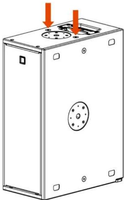
natural_image
Technical line drawing of a rectangular industrial enclosure with mounting holes and a central circular component (no text or symbols)6. FLOOR CONFIGURATIONS
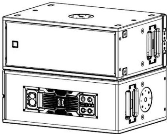
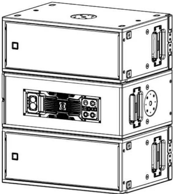
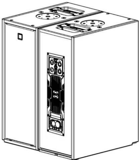
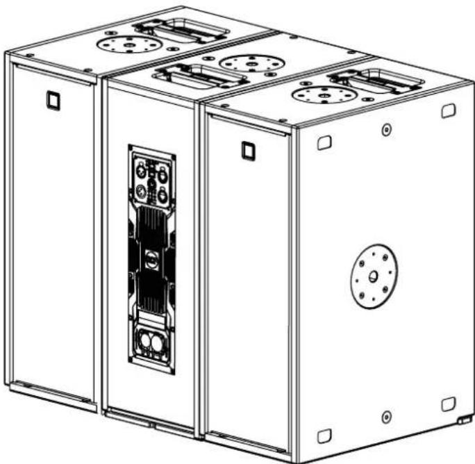
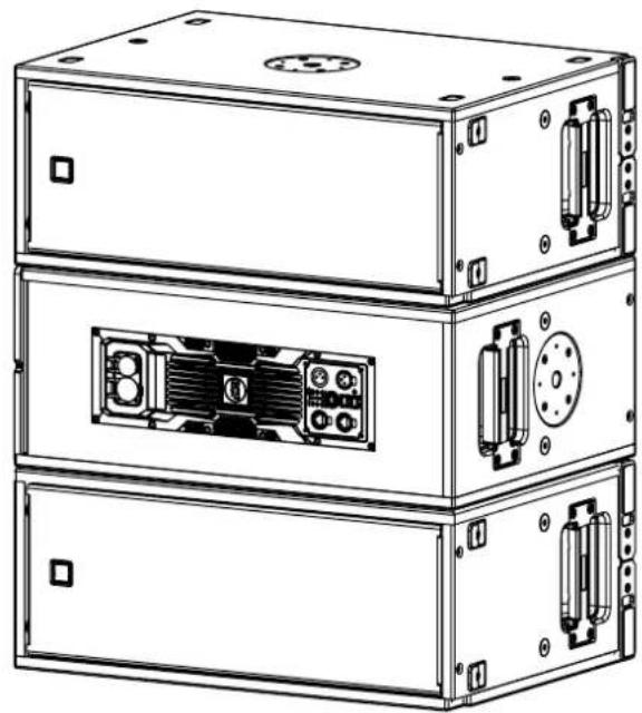
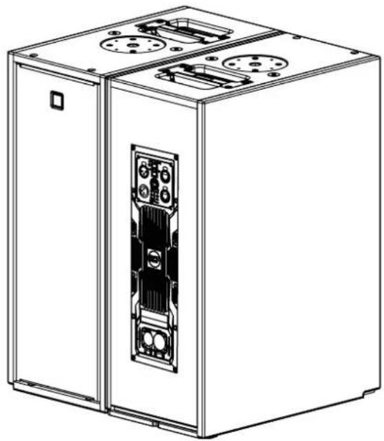
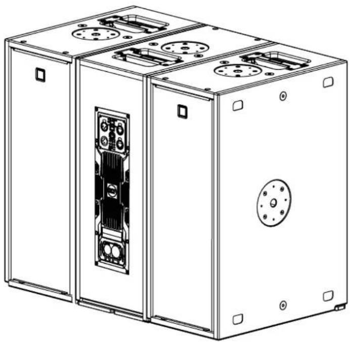
Using the specific preset on RDNet, SUB 808-AS can be used in cardioid configuration, either in horizontal and vertical position.
natural_image
Technical line drawing of a dual-tier electronic device with ports and connectors (no text or symbols)2 x SUB 808-AS CARDIOID CONFIGURATION HORIZONTAL SETUP
natural_image
Technical line drawing of three stacked electronic equipment units with visible ports and connectors (no text or symbols)3 x SUB 808-AS CARDIOID CONFIGURATION HORIZONTAL SETUP
natural_image
Line drawing of a two-port electrical enclosure with internal components and mounting holes (no text or symbols)2 x SUB 808-AS CARDIOID CONFIGURATION VERTICAL SETUP
natural_image
Technical line drawing of a multi-compartment industrial machine with internal components and mounting holes (no text or symbols)3 x SUB 808-AS CARDIOID CONFIGURATION VERTICAL SETUP
7. SUSPENDED CONFIGURATIONS
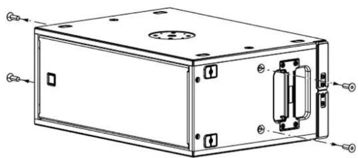
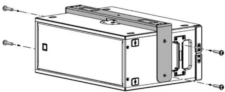
With the use of the vertical bracket it is possible to suspend one or two subwoofers SUB 808-AS.
- Remove the four M10 screws from both the sides of the speakers.
natural_image
Technical line drawing of a rectangular electronic device with mounting holes and internal components (no text or symbols)- Place the bracket over the speaker and screw it to the cabinet with the four M10 screws (and washers) provided.
natural_image
Technical line drawing of a rectangular electronic device with mounting holes and internal components (no text or symbols)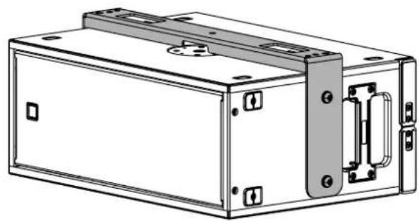
natural_image
Technical line drawing of a rectangular electronic device with mounting holes and internal components (no text or symbols)7. SUSPENDED CONFIGURATIONS
An additional subwoofer SUB 808-AS can be placed below the first one with the use of two linking brackets.
- Remove the four M10 screws from both the sides of the speakers.
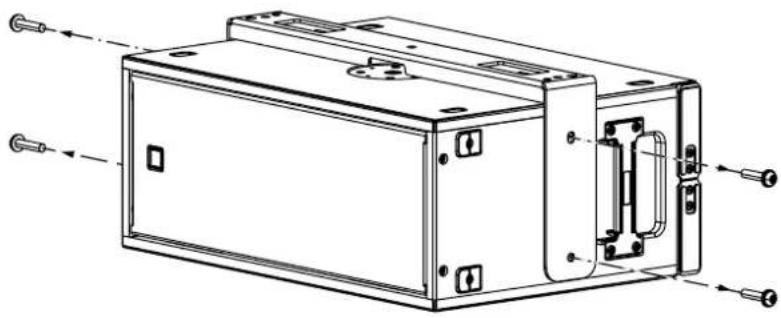
natural_image
Technical line drawing of a mechanical enclosure with mounting holes and internal components (no text or symbols)- Place the linking brackets on both sides (as shown in the picture) and screw them to the cabinet with the same M10 screws (and washers) removed earlier.
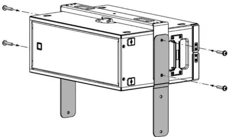
natural_image
Technical line drawing of a mechanical device with mounting flanges and internal components (no text or symbols)- Place the second subwoofer in cardioid configuration and screw the bracket to it with the M10 screws provided.
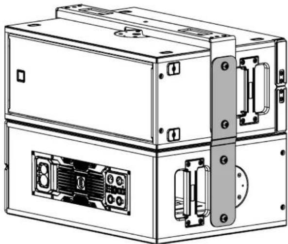
natural_image
Technical line drawing of a multi-tiered electronic device with ports and connectors (no text or symbols)
NOTE: The same operations must be done on both sides of the speaker

NOTE: A maximum of two SUB 808-AS can be suspended with the vertical bracket.
7. SUSPENDED CONFIGURATIONS
With the use of the Link Bar it is possible to suspend a KX 515-A below a single suspended SUB 808-AS.
- Loosen the M10 upper screw and completely remove the lower M10 screw.
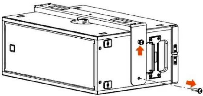
natural_image
Technical line drawing of a mechanical housing or enclosure with internal components and directional arrows indicating movement (no text or symbols)- Place the link bars on both sides and letting the upper screw pass through the circular bottomhole; then screw back the lower screw (do not tighten the screw yet).
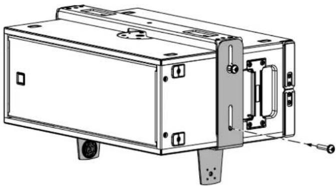
natural_image
Technical line drawing of a mechanical enclosure or housing with mounting holes and internal components (no text or symbols)- Pull down the bracket and tighten both the upper and lower screw.

natural_image
Technical line drawing of a mechanical device with mounting holes and a handle (no text or symbols)7. SUSPENDED CONFIGURATIONS
- Place a KX 515-A between the two brackets and fix it by placing the two knobs or bolts provided.
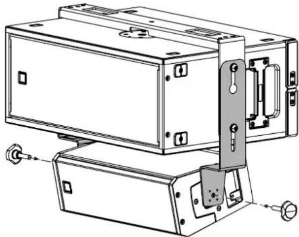
natural_image
Technical line drawing of a mechanical device with mounting base and clamping mechanism (no text or symbols)- Choose the right inclination and tighten the bolts or knobs.
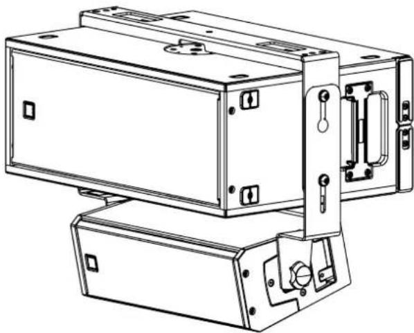
natural_image
Technical line drawing of a mechanical device with mounting brackets and control knobs (no text or symbols)
NOTE: The same operations must be done on both sides of the speaker

NOTE: This configuration can be only done with one SUB 808-AS and one KX 515-A.
8. TROUBLESHOOTING
Make sure the speaker is switched on and connected to an active AC power
THE SPEAKER IS CONNECTED TO AN ACTIVE AC POWER BUT DOESN'T TURN ON
Make sure the power cable is intact and connected correctly.
Check if the signal source is sending correctly and if the signal cables are not damaged.
THE SOUND IS DISTORTED AND THE OVERLOAD LED BLINKS FREQUENTLY
Turn down the output level of the mixer.
THE SOUND IS VERY LOW AND HISSING
The source gain or the output level of the mixer might be too low.
THE SOUND IS HISSING EVEN AT PROPER GAIN AND VOLUME
The source might send a low quality or noisy signal
HUMMING OR BUZZING NOISE
Check out the AC grounding and all the equipments connected to the mixer input including cables and connectors.

WARNING! to reduce the risk of electric shock, do not disassemble this product unless you are qualified. Refer servicing lifted service personnel.
1. AVVERTENZE PER LA SICUREZZA E INFORMAZIONI GENERALI
DISPOSITIVI PASSIVI e ACCESSORI
natural_image
Technical line drawing of a rectangular electronic enclosure with mounting holes and internal components (no text or symbols)SUB 808-AS
2000 Watt 2 X 8" Woofer ventilati 19,5 Kg (43 lbs)
3. PANNELLO POSTERIORE - FUNZIONI E CONTROLLI
natural_image
Technical line drawing of a cylindrical mechanical component with three labeled ports (no text or symbols present)PIN 1 = TERRA (GROUND; SHIELD)
PIN 2 = LATO CALDO (HOT; +)
PIN 3 = LATO FREDDO (COLD; -)
CONNETTORE JACK TS
Connessione mono sbilanciata
CONNETTORE JACK TRS
Connessione mono bilanciata
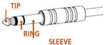
SLEEVE = TERRA (GROUND ;SHIELD)
TIP = LATO CALDO (HOT; +)
RING = LATO FREDDO (COLD; -)
PRIMA DI CONNETTERE IL DIFFUSORE
natural_image
Technical line drawing of a server rack unit with mounting base and internal circuit panel (no text or symbols)natural_image
Technical line drawing of a rectangular electronic device with mounting holes and internal components (no text or symbols)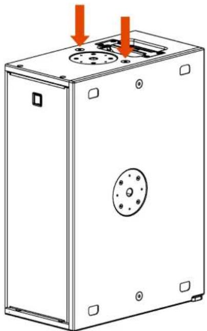
natural_image
Technical line drawing of a rectangular electronic enclosure with mounting holes and a central circular component (no text or symbols)natural_image
Technical line drawing of a dual-chamber electronic device with ports and connectors (no text or symbols)2 x SUB 808-AS CONFIGURAZIONE CARDIOIDE SETUP ORIZZONTALE
natural_image
Technical line drawing of three stacked electronic equipment units with visible ports and connectors (no text or symbols)3 x SUB 808-AS CONFIGURAZIONE CARDIOIDE SETUP ORIZZONTALE
natural_image
Line drawing of a two-port industrial enclosure with internal components and mounting holes (no text or symbols)2 x SUB 808-AS CONFIGURAZIONE CARDIOIDE SETUP VERTICALE
natural_image
Technical line drawing of a multi-compartment electrical enclosure with internal components and mounting holes (no text or symbols)3 x SUB 808-AS CONFIGURAZIONE CARDIOIDE SETUP VERTICALE
natural_image
Technical line drawing of a rectangular electronic device with mounting holes and internal components (no text or symbols)natural_image
Technical line drawing of a rectangular electronic device with mounting holes and internal components (no text or symbols)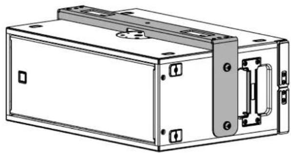
natural_image
Technical line drawing of a rectangular electronic device with mounting holes and internal components (no text or symbols)natural_image
Technical line drawing of a mechanical enclosure with mounting holes and internal components (no text or symbols)natural_image
Technical line drawing of a mechanical device with mounting flanges and internal components (no text or symbols)natural_image
Technical line drawing of a multi-tiered electronic device with ports and connectors (no text or symbols)
natural_image
Technical line drawing of a mechanical device with internal components and directional arrows indicating movement (no text or symbols)natural_image
Technical line drawing of a mechanical enclosure or housing with mounting holes and internal components (no text or symbols)natural_image
Technical line drawing of a mechanical housing or enclosure with mounting feet and internal components (no text or symbols)natural_image
Technical line drawing of a mechanical device with mounting base and clamping mechanism (no text or symbols)natural_image
Technical line drawing of a mechanical device with mounting brackets and control knobs (no text or symbols)
Acoustical specifications Frequency Response: 40 Hz ÷ 400 Hz
Max SPL @ 1m: 129 dB
Transducers Woofer: 2 x 8" neo, 2.5" v.c
Input/Output section Input signal: bal/unbal
Input connectors: XLR, RDNet Ethercon
Output connectors: XLR, RDNet Ethercon
Input sensitivity: -2 dBu/+4 dBu
Processor section Protections: Excurs.
Limiter: Fast Limiter
Controls: Gain, Equalization, ByPass on board
RDNet: Yes
Power section Total Power:
2000 W Peak
Low frequencies: 2000 W Peak
Cooling: Convection
Connections: PowerCON TRUE1 TOP
Standard compliance CE marking: Yes
Physical specifications
Cabinet/Case Material: Baltic birch plywood
Hardware: 2X M20 TOP AND SIDE 8X M10 2X SIDE
Handles: 1 X SIDE
Grille: Steel
Color: Black
Size
Height: 243.5 mm / 9.59 inches
Width: 603.5 mm / 23.76 inches
Depth: 430 mm / 16.93 inches
Weight: 20 kg / 44.09 lbs
Shipping informations
Package Height: 290 mm / 11.42 inches
Package Width: 480 mm / 18.9 inches
Package Depth: 650 mm / 25.59 inches
Package Weight: 21 kg / 46.3 lbs

- SAFETY PRECAUTIONS AND GENERAL INFORMATION
- IMPORTANT
- SAFETY PRECAUTIONS
- GENERAL SAFETY PRECAUTIONS
- ACTIVE DEVICES: ACTIVE SPEAKERS and AMPLIFIERS
- PASSIVE DEVICES and ACCESSORIES
- SUSPENDED DEVICES
- OPERATING PRECAUTIONS
- CORRECT DISPOSAL OF THIS PRODUCT
- CARE AND MAINTENANCE
- DESCRIPTION
- SUB 808-AS - PROFESSIONAL ACTIVE SUBWOOFER
- REAR PANEL FEATURES AND CONTROLS
- CONNECTIONS
- PROTECTIONS
- VOLTAGE SETUP (RESERVED TO THE RCF SERVICE CENTRE)
- INSTALLATION
- FLYING POINTS
- FLOOR CONFIGURATIONS
- SUSPENDED CONFIGURATIONS
- TROUBLESHOOTING
- THE SPEAKER IS CONNECTED TO AN ACTIVE AC POWER BUT DOESN'T TURN ON
- THE SOUND IS DISTORTED AND THE OVERLOAD LED BLINKS FREQUENTLY
- THE SOUND IS VERY LOW AND HISSING
- THE SOUND IS HISSING EVEN AT PROPER GAIN AND VOLUME
- HUMMING OR BUZZING NOISE
- AVVERTENZE PER LA SICUREZZA E INFORMAZIONI GENERALI
- DISPOSITIVI PASSIVI e ACCESSORI
- PANNELLO POSTERIORE - FUNZIONI E CONTROLLI
- PRIMA DI CONNETTERE IL DIFFUSORE
Brand : RCF
Model : SUB 808-AS
Category : Subwoofer