
ADDERLink X50-MS - Audio/video extender Adder - Free user manual and instructions
Find the device manual for free ADDERLink X50-MS Adder in PDF.


| Product Type | Audio/Video Extender |
| Brand | Adder |
| Model | ADDERLink X50-MS |
| Video Interface | HDMI |
| Max Video Resolution | 1920x1080 @ 60Hz |
| Audio Support | Embedded HDMI audio |
| USB Support | USB 2.0 (Keyboard/Mouse) |
| Transmission Medium | Cat5e/6 UTP cable |
| Maximum Distance | 150 meters @ 1080p |
| Power Supply | External 5V DC, 2A |
| Dimensions (WxDxH) | 210 x 150 x 30 mm |
| Weight | 0.5 kg |
| Operating Temperature | 0°C to 40°C |
| Storage Temperature | -20°C to 60°C |
| Humidity | 20% to 80% non-condensing |
| Housing Material | Metal |
| Mounting | Desktop or rack mountable (bracket sold separately) |
| Indicators | Power, Link, Video |
| Maintenance | Wipe with dry, lint-free cloth; do not use liquids |
| Safety | Use only included power adapter; avoid moisture; ensure ventilation |
| Spare Parts & Repairability | Contact Adder support for service; no user-serviceable parts inside |
Frequently Asked Questions - ADDERLink X50-MS Adder
User questions about ADDERLink X50-MS Adder
0 question about this device. Answer the ones you know or ask your own.
Ask a new question about this device
Download the instructions for your Audio/video extender in PDF format for free! Find your manual ADDERLink X50-MS - Adder and take your electronic device back in hand. On this page are published all the documents necessary for the use of your device. ADDERLink X50-MS by Adder.
USER MANUAL ADDERLink X50-MS Adder
Connections at the remote module....8
Dual user configuration ....10
Video display (DDC) information....11
Video sharpness adjustment....12
Operation
General use 13
Dual user arbitration....13
Peripheral operation....13
Further information
Getting assistance....14
Troubleshooting....14
Warranty 15
Safety information 15
Radio Frequency Energy....16

Welcome

Introduction
Thank you for choosing the Adder X50 USB extenders which provide a very effective way to put distance between your computer and its peripherals. The compact casings and ease of use of the Adder X50 modules belie the ingenuity of their operation. Using our proprietary transmission techniques we are able to reliably transfer more signals than ever before along a single length of Category 5, 5e or 6 twisted pair cabling. What this means for you is that your video, audio, USB keyboard, USB mouse and two other USB channels are all readily and reliably available at up to 50 metres away.
Using the Adder X50 extenders does not mean that you need to compromise on functionality in any way. Our highly efficient transmission methods mean that high video resolutions of up to 1920 x 1440 are supported together with CD quality digital sound that produces no crackles - even in the quietest interludes. The USB connections are seamless and thanks to our unique 'Bi-tripos' circuitry, four full speed USB 2.0 devices can be used simultaneously with full support for disconnect/re-connect at any time without causing errors.
The Adder X50 extenders have been designed to be quick to install and totally transparent in operation. All connectors are industry standard and the video sharpness adjustments are made using a simple rotary dial.
Where dual screens are required, an MS2 variant provides double video channels in addition to full support for an RS232 serial device. So whether you are extending your workplace or creating a cost-effective distributed audio visual system, the X50 extenders provide the power and flexibility to create the right solution.

flowchart
graph LR
    PC["PC"] -->|VIDEO 1, VIDEO 2*, AUDIO, RS232 SERIAL*, USB| X50["X50"]
    X50 -->|CATx link cable(s)*| ADDER["ADDER"]
    X50 -->|Upto50metres separation| ADDERLX["X50"]
    ADDERLX -->|REMOTE| ADDER
    ADDERLX -->|USB device, USB device, Serial device| ADDER
    ADDERLX -->|USB device, USB device, Serial device| ADDER
* Secondary video, RS232 serial and a second link cable are available only with the X50 MS2 variant
Supplied items

X50 MS2 variant extender modules

natural_image
Illustration of a X50 M52 local module device with ports and connectors (no text or symbols on the device itself)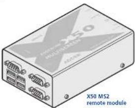
natural_image
Illustration of a X50 MS2 remote module with ports and connectors (no text or symbols on the device itself)The MS2 variant package includes all of the above ancillary items plus:


Optional items

natural_image
Line drawing of a rectangular electronic device with a coiled cable and connector (no text or symbols)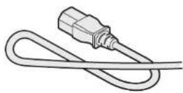
Power adapter and country-specific power lead for local module (if USB powering not possible)
Part number: PSU-IFC-5VDC-2.5A

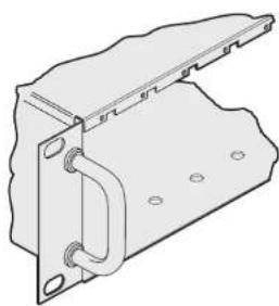
Rack mount plate for X50 standard module (useable for the local or remote modules) Part number: X-RMK-FASCIA

Rack mount plate for X50 MS2 module (usable for the local or remote modules) Part number: X-RMK-FASCIA-DUAL
natural_image
Technical line drawing of a metal bracket with mounting holes and a curved internal component (no text or symbols)Rack mount chassis Part number: X-RMK-CHASSIS

Installation
Connections
Installation of the X50 modules is straightforward with minimal configuration requirements in most cases.
• Connections at the local module
• Connections at the remote module
Important
Do not attach a USB hub to the X50 remote, nor plug the X50 local module into another USB hub. To do so will reduce the maximum cable length over which the system will extend USB; also, some USB hubs may not provide enough power to operate the local unit.
Do not use USB cables that are longer than 3 metres to connect the local module to the computer or to connect the remote module to the USB peripherals.
Mounting
The X50 modules offer two main mounting methods:
• Supplied four self-adhesive rubber feet
- Rack mount brackets - see below


Connections at the local module
1 Where possible ensure that power is disconnected from the computer system to be connected.
2 Attach the video, USB (see the Important note on page 5) and (optionally) audio connections from the computer system to the relevant sockets on the local module.

Note: Do not use a USB cable that is longer than 3 metres to connect the local module to the computer system.
![[MS2 variant only] Optionally attach a second video input from the computer system to the upper video in socket on the MS2 local module. To secondary video output port](/content/2026/05/912555/images/fb5b1efbefaf4baed3b660788e17f434dc7130f8315bf95e426cb42ba9493f65.jpg)
3 Optionally connect local speakers to the audio output connector on the local module.

4 Optionally connect a local video monitor to the video out feed-through connector on the local module.

![[MS2 variant only] Optionally attach a second video monitor to the upper video out socket on the MS2 local module. Tosecondary local monitor](/content/2026/05/912555/images/bfc9e07366edcda6ae0106fb053878028e920bf9d4651aa18db5a06de988b898.jpg)


![[MS2 variant only] Attach the connector of a second category 5, 5e or 6 link cable (up to 50 metres in length) to the 'LINK 2' socket on the MS2 local module. Secondary link to remote module](/content/2026/05/912555/images/3d85ba5d05f1a4194f8b07bd4820868dfa791ff680e084e60b270422513b6f52.jpg)
![6 [MS2 variant only] Optionally attach a serial connection lead to the female connector on the MS2 local module and attach the other end to a vacant serial port on your computer. To computer serial port](/content/2026/05/912555/images/bba3141395fd981894685b6c26089a4f83b9805134e0b9a5088dc6ec7d7c319d.jpg)
Local module power
In the majority of installations, the local module will derive all of its power successfully from the USB link with the computer system. However, if insufficient voltage is available from the computer system, the green indicator adjacent to the link connector will flash. If this occurs (or if you do not intend to use the USB connection with the computer) you will need to purchase and use a power supply identical to the one used for the remote module (part number: PSU-IEC-5VDC-2.5A) from your Adder stockist.
1 If external power input is necessary, attach the output connector of the optional power supply to the 'POWER' socket of the local module.
2 Attach the IEC power lead to the power supply body and insert the mains plug of the lead to a nearby power outlet.
Note: If a power adapter is plugged into the module but not switched on, it will prevent the unit from deriving power from the USB connection.

Connections at the remote module
1 Place the remote module adjacent to the user location.
2 Attach the lead from the video monitor to the video out socket on the remote module.
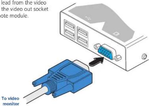
![[MS2 variant only] Optionally attach the lead from a second video monitor to the upper video out socket on the MS2 remote module. To secondary video monitor](/content/2026/05/912555/images/13641d3380a74c048648576a2752b1f64ee31d3e54ddaa3c72caadf11385ee3c.jpg)
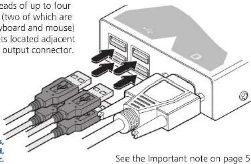
3 Attach the leads of up to four USB devices (two of which are usually a keyboard and mouse) to the sockets located adjacent to the video output connector.
To USB devices, e.g. keyboard, mouse, etc.
[MS2 variant only] Note: When connecting four USB devices to the unit, ensure that their total power requirements do not exceed 1700mA (1.7A). The USB standard states a maximum allowable current draw of 500mA (0.5A) per device, although most devices remain well below this limit - USB keyboards and mice typically require 100mA. Each X50 contains a self-resetting fuse that will prevent damage by shutting down the unit if the total power draw becomes excessive.
![4 [MS2 variant only] Optionally attach a serial device lead to the male serial connector on the remote module. To RS232 serial device](/content/2026/05/912555/images/1efb64e3fdfc18a0a765dab83ecb241aba4607abdd79d5ff234981299468b4df.jpg)


![[MS2 variant only] Attach the connector of a second category 5, 5e or 6 link cable (up to 50 metres in length) to the 'LINK 2' socket on the MS2 remote module. Secondary link to remote module](/content/2026/05/912555/images/3bbb4f34afe8171e40790e4e23c8a54feb2791049de5fdc3cbdeac179009fdf5.jpg)
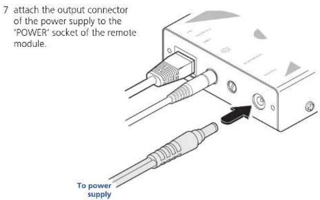
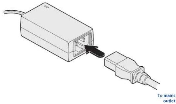
8 Attach the IEC power lead to the power supply body and insert the mains plug of the lead to a nearby power outlet.
natural_image
Diagram of a device with an attached plug and cable, showing no text or symbols on the diagram itself.
Dual user configuration
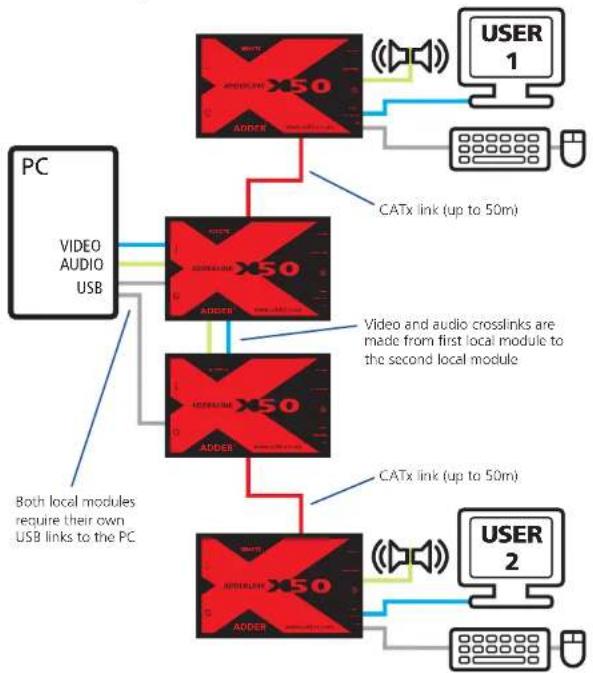
You can combine two Adder X50 extender sets to create a dual user configuration. Such an installation would allow a single computer to be controlled from two different positions, with each position receiving the same audio visual output and having equal and concurrent control over the computer. Arbitration between the two positions is handled by the computer's USB system and so this arrangement is better suited to situations where two users would not often require simultaneous access.
flowchart
graph TD
    PC["PC"] -->|Video and audio crosslinks are made from first local module to the second local module| X50_1["X50 ADDR"]
    PC -->|Video and audio crosslinks are made from first local module to the second local module| X50_2["X50 ADDR"]
    PC -->|Video and audio crosslinks are made from first local module to the second local module| X50_3["X50 ADDR"]
    PC -->|Video and audio crosslinks are made from first local module to the second local module| X50_4["X50 ADDR"]
    PC -->|Video and audio crosslinks are made from first local module to the second local module| X50_1
    PC -->|Video and audio crosslinks are made from first local module to the second local module| X50_2
    PC -->|Video and audio crosslinks are made from first local module to the second local module| X50_3
    PC -->|Video and audio crosslinks are made from first local module to the second local module| X50_4
    PC -->|Video and audio crosslinks are made from first local module to the second local module| X50_1
    PC -->|Video and audio crosslinks are made from first local module to the second local module| X50_2
    PC -->|Video and audio crosslinks are made from first local module to the second local module| X50_3
    PC -->|Video and audio crosslinks are made from first local module to the second localized module| X50_4
    PC -->|Video and audio crosslinks are made from first localized module to the second localized module| X50_1
    PC -->|Video and audio crosslinks are made from first localized module to the second localized module| X50_2
    PC -->|Video and audio crosslinks are made from first localized module to the second localized module| X50_3
    PC -->|Video and audio crosslinks are made from first localized module to the second localized module| X50_4

Most of the connections are similar to the standard configuration. The main difference is in the links to the second local module. Use an audio link lead to connect the audio out socket of the first local module to the audio in socket of the second. Similarly, use a video link lead to connect the video out and video in ports. The second local module then requires its own USB link directly to the computer. In all other respects follow the standard instructions to connect CATx links and all of the remote module connections.

Video display (DDC) information
The Display Data Channel (or DDC) is an industry standard scheme which allows video monitors to declare their capabilities to the computer's video adapter circuitry, allowing the latter to optimise their outputs accordingly. Since the widespread adoption of the scheme, video adapters have become increasingly dependent on receiving relevant DDC information during startup, before they will output anything more than a rudimentary video signal.
It is not possible to transmit DDC data back from the video monitor that is attached to the remote module to the computer's video adapter. Therefore, during startup of the local module, it will search for a video monitor connected to its local feed-through connector:
- If a local video monitor is found, its DDC information will be compared to the information already stored and, if different, will be copied, stored and presented to the video adapter upon request.
- If no local video monitor is found, the local module will make available its previously stored set of DDC parameters to the video adapter upon request; or, if none were stored, a default set.
In either case, the DDC information taken by the video adapter will be used to determine the video output that is sent via the X50 modules to the remote monitor.
If you find that the default DDC information is not completely suitable for your remote monitor, try temporarily connecting your remote monitor to the video out port of the local module. When the local module is powered up, it will read and store the DDC information from your monitor. You can then return the monitor to its remote position and the new DDC information will be used at every power on.
DDC indications
When power is first applied to the local module (either from the computer's USB port or an optional power adapter) it will search for valid DDC data on its video out connector. During this process, the yellow indicator (built into the link connector) will flash to indicate its progress:

- If no valid DDC information is located, the yellow indicator will give one very short flash, representing an attempt to read data. No changes will be made to the information already stored within the local module.
- If the DDC information is the same as that already stored, no change will be made and the yellow indicator will give one single flash as the information is checked and normal operation resumes.
- If different DDC information is located, the yellow indicator will flash rapidly for 2 to 3 seconds while the new information is stored. A single flash will then be given as the information is checked and normal operation resumes.
The local module's yellow indicator also provides fault indications to assist with troubleshooting:
- Two flashes - Checksum error prior to copying - no information will be programmed.
- Three flashes - Too much data to fit into the module - the module can hold a maximum of two pages of DDC information.
- Rapid flashing followed by four flashes - data was lost during copying - the default data was substituted. Repeat the power on process.
- Rapid flashing followed by five flashes - Checksum error during copying - the default data was substituted. Repeat the power on process.

Video sharpness adjustment
The Adder X50 remote module includes a straightforward video adjustment to control picture sharpness on the remote monitor.
To adjust video sharpness
1 On the computer, display a suitable high contrast image (see right).
2 Insert a small flat-bladed screwdriver into the SHARPNESS adjustment hole so that it engages with the slot in the rotary dial.
3 Turn the rotary dial fully clockwise - you should see a bright white shadow to the right of your high contrast image:
4 Turn the rotary dial anti-clockwise until the white shadow disappears and the edges of your image become sharp.
The remote module for the dual video MS2 variant includes two separate sharpness adjustments for each video channel (the upper dial corresponds to the upper video output socket).


Sharpness control for the first (A) video channel
To display a suitable high contrast image The best way to clearly view the effect of sharpness and brightness adjustments is to display a high contrast image, with vertical edges, on the screen.
- Open a word processor, type the capital letter 'H', or 'M' and increase the point size to 72 or higher. For best results, the background should be white and the character should be black.


Operation
General use
In use, the X50 modules should be transparent - the system and its peripherals should operate exactly as normal, the only difference being that they are now up to 50 metres apart.
In some installations, you may see some 'shadows' to the right of high contrast screen characters. This can be caused by an incorrectly selected sharpness setting and it may be necessary to make adjustments to correct this. Please see Video sharpness adjustment in the 'Installation' section.
Dual user arbitration
When using two sets of X50 modules to allow two users to access a single computer, be aware that arbitration between the users is handled by the USB sub-system of the computer. Unlike with other Adder products, this means that both users can control the computer at exactly the same time and the resulting keyboard and mouse influences will be an amalgam of the two inputs - i.e. a mouse move to the right by one user will cancel out a simultaneous left mouse move by the other. The same is also true when the local module has feed-through peripherals attached to it, adjacent to the computer.
For this reason, the X50 dual user arrangement is better suited to situations where two users would not often require simultaneous access.
Peripheral operation
USB
Each X50 remote module provides four USB outlets, each of which can support USB 2.0 peripherals at speeds up to 12Mbps. The X50 appears to the computer as a four port USB hub.
If the link between the modules is interrupted, any connected USB peripherals will be automatically disabled and re-enabled once the connection is restored. [MS2 variant only] Note: When connecting four USB devices to the unit, ensure that their total power requirements do not exceed 1700mA (1.7A). The USB standard states a maximum allowable current draw of 500mA (0.5A) per device, although most devices remain well below this limit - USB keyboards and mice typically require 100mA. Each X50 contains a self-resetting fuse that will prevent damage by shutting down the unit if the total power draw becomes excessive.
RS232 serial
The MS2 variant modules provide additional support for an RS232 device. The 9 way male D-type socket on the remote module supports speeds up to 115,200 baud and all PC-AT flow control pins are supported.

Further information
Getting assistance
If you are still experiencing problems after checking the information contained within this guide, then we provide a number of other solutions:
- Online solutions and updates – www.adder.com/support Check the Support section of the adder.com website for the latest solutions and firmware updates.
- Adder Forum – forum.adder.com Use our forum to access FAQs and discussions.
- Technical support – www.adder.com/contact-support-form For technical support, use the contact form in the Support section of the adder.com website - your regional office will then get in contact with you.
Troubleshooting
Status indicators
The green and yellow indicators built into the link connectors on each module provide useful feedback regarding the connection and power status:
During startup (of the local module)
- One very short yellow flash: no valid DDC information available from a locally connected video monitor, no changes made to stored DDC information.
- Single yellow flash: DDC information being read from a locally connected video monitor, but no changes made to stored DDC information.
- Rapid yellow flash for 2 to 3 seconds, followed by single flash: New DDC information being read and stored from a locally connected video monitor.
- Two yellow flashes - Checksum error prior to copying - no information will be programmed.
- Three yellow flashes - Too much data to fit into the module - the module can hold a maximum of two pages of DDC information.
- Rapid yellow flashing followed by four flashes - data was lost during copying - the default data was substituted. Repeat the power on process.
- Rapid yellow flashing followed by five flashes - Checksum error during copying - the default data was substituted. Repeat the power on process.
During operation (either module)
• Continual yellow: Valid CATx link to other module sensed.
• Continual green: Correct power input sensed.
- Green flashes: Power input too low for normal operation. In the case of the local module, this may be because the USB connection is unable to provide sufficient power. In these cases, an external power supply should be used with the local module.
Important
Do not attach a USB hub to the X50 remote, nor plug the X50 local module into another USB hub. To do so will reduce the maximum cable length over which the system will extend USB; also, some USB hubs may not provide enough power to operate the local unit.
Do not use USB cables that are longer than 3 metres to connect the local module to the computer or to connect the remote module to the USB peripherals.

Warranty
Adder Technology Ltd warrants that this product shall be free from defects in workmanship and materials for a period of two years from the date of original purchase. If the product should fail to operate correctly in normal use during the warranty period, Adder will replace or repair it free of charge. No liability can be accepted for damage due to misuse or circumstances outside Adder's control. Also Adder will not be responsible for any loss, damage or injury arising directly or indirectly from the use of this product. Adder's total liability under the terms of this warranty shall in all circumstances be limited to the replacement value of this product.
If any difficulty is experienced in the installation or use of this product that you are unable to resolve, please contact your supplier.
Safety information
• For use in dry, oil free indoor environments only.
• Do not use to link between buildings.
- Ensure that all twisted pair interconnect cables are installed in compliance with all applicable wiring regulations.
- Do not connect CATx link interfaces (RJ45 style connectors) to any other equipment, particularly network or telecommunications equipment.
- Warning – the power adapter contains live parts.
- No user serviceable parts are contained within the power adapter - do not dismantle.
- Plug the power adapter into a socket outlet close to the module that it is powering.
- Replace the power adapter with a manufacturer approved type only.
- Do not use the power adapter if the power adapter case becomes damaged, cracked or broken or if you suspect that it is not operating properly.
- If you use a power extension cord with the remote module, make sure the total ampere rating of the devices plugged into the extension cord do not exceed the cord's ampere rating. Also, make sure that the total ampere rating of all the devices plugged into the wall outlet does not exceed the wall outlet's ampere rating.
- Do not attempt to service the modules yourself.
- The power supply can get warm in operation – do not situate it in an enclosed space without any ventilation.

Radio Frequency Energy
A Category 5 (or better) twisted pair cable must be used to connect the units in order to maintain compliance with radio frequency energy emission regulations and ensure a suitably high level of immunity to electromagnetic disturbances. All other interface cables used with this equipment must be shielded in order to maintain compliance with radio frequency energy emission regulations and ensure a suitably high level of immunity to electromagnetic disturbances.
European EMC directive 89/336/EEC
This equipment has been tested and found to comply with the limits for a class A computing device in accordance with the specifications in the European standard EN55022. These limits are designed to provide reasonable protection against harmful interference. This equipment generates, uses and can radiate radio frequency energy and if not installed and used in accordance with the instructions may cause harmful interference to radio or television reception. However, there is no guarantee that harmful interference will not occur in a particular installation. If this equipment does cause interference to radio or television reception, which can be determined by turning the equipment on and off, the user is encouraged to correct the interference with one or more of the following measures: (a) Reorient or relocate the receiving antenna. (b) Increase the separation between the equipment and the receiver. (c) Connect the equipment to an outlet on a circuit different from that to which the receiver is connected. (d) Consult the supplier or an experienced radio/TV technician for help.
FCC Compliance Statement (United States)
This equipment generates, uses and can radiate radio frequency energy and if not installed and used properly, that is, in strict accordance with the manufacturer's instructions, may cause interference to radio communication. It has been tested and found to comply with the limits for a class A computing device in accordance with the specifications in Subpart J of part 15 of FCC rules, which are designed to provide reasonable protection against such interference when the equipment is operated in a commercial environment. Operation of this equipment in a residential area may cause interference, in which case the user at his own expense will be required to take whatever measures may be necessary to correct the interference. Changes or modifications not expressly approved by the manufacturer could void the user's authority to operate the equipment.
Canadian Department of Communications RFI statement
This equipment does not exceed the class A limits for radio noise emissions from digital apparatus set out in the radio interference regulations of the Canadian Department of Communications.
Contact: www.adder.com/contact-details
Support: forum.adder.com
Documentation by: www.ctxd.com

© 2012 Adder Technology Limited
All trademarks are acknowledged.
Part No. MAN-X50_X50-MS2 • Release 1.1d


- Operation
- Further information
- Welcome
- Introduction
- Optional items
- Installation
- Connections
- Important
- Mounting
- Connections at the local module
- Local module power
- Connections at the remote module
- Dual user configuration
- Video display (DDC) information
- DDC indications
- Video sharpness adjustment
- To adjust video sharpness
- To display a suitable high contrast image The best way to clearly view the effect of sharpness and brightness adjustments is to display a high contrast image, with vertical edges, on the screen.
- General use
- Dual user arbitration
- Peripheral operation
- USB
- RS232 serial
- Getting assistance
- Troubleshooting
- Status indicators
- During startup (of the local module)
- During operation (either module)
- Warranty
- Safety information
- Radio Frequency Energy
- European EMC directive 89/336/EEC
- FCC Compliance Statement (United States)
- Canadian Department of Communications RFI statement
Brand : Adder
Model : ADDERLink X50-MS
Category : Audio/video extender