
ALIF2020R - Audio/video extender Adder - Free user manual and instructions
Find the device manual for free ALIF2020R Adder in PDF.


| Product Type | Audio/Video Extender (Receiver) |
| Model | AdderLink Infinity ALIF2020R |
| Dimensions (W x H x D) | 198 mm x 44 mm x 150 mm (7.92 x 1.76 x 6.0 in) |
| Weight | 1.1 kg (2.4 lbs) |
| Power Supply | 5 VDC, 20 W adapter; Input: 100-240 VAC, 50/60 Hz, 0.8 A |
| Video Input | Dual single-link DVI-D up to 1920 x 1200 @ 60 Hz per port |
| Audio | Stereo line in/out (3.5 mm jacks); microphone support with +20 dB boost |
| USB | 4 x USB 2.0 ports (Type A) for peripherals; total current 1.2 A |
| Serial (AUX) | RS-232, null-modem cable, up to 115200 baud (software flow control) |
| Network Interfaces | System port (Gigabit Ethernet RJ45), Teaming port (SFP slot for fiber or copper) |
| Management Port | Dedicated RJ45 for configuration (default IP: 192.168.1.42) |
| Video Compression | AFZ lossless, AFZ+ lossy; Magic Eye anti-dither; frame skipping |
| Encryption | TLS for control data; USB encryption selectable |
| Supported Configurations | One-to-one, one-to-many (multicast); up to 13 concurrent USB inputs |
| Operating Temperature | 0°C to 40°C (32°F to 104°F) |
| Cleaning | Wipe with a dry, lint-free cloth; do not use liquids or solvents |
| Safety | Indoor use only; no user serviceable parts; use only supplied power adapter |
| Spare Parts & Repairability | Optional SFP modules, rack brackets, VESA mount, cables; contact supplier for repair |
| Warranty | 2 years from original purchase (defects in workmanship/materials) |
| Regulatory Approvals | CE, FCC Class A |
Frequently Asked Questions - ALIF2020R Adder
User questions about ALIF2020R Adder
0 question about this device. Answer the ones you know or ask your own.
Ask a new question about this device
Download the instructions for your Audio/video extender in PDF format for free! Find your manual ALIF2020R - Adder and take your electronic device back in hand. On this page are published all the documents necessary for the use of your device. ALIF2020R by Adder.
USER MANUAL ALIF2020R Adder
ANE LEA VND NUQ AEA AE2 TEN



Experts in Connectivity Solutions

KVM Extension Solutions
Contents
Introduction
Welcome....2
ALIF features....3
Firmware version 3.3 (or greater) 4
AdderLink Infinity (1002) unit features....5
AdderLink Infinity dual unit features 6
Supplied items - ALIF 1002 7
Supplied items - ALIF dual....8
Optional extras....9
Installation
Connections....10
Mounting....10
TX video link....11
TX audio links....12
TX USB link....12
TX AUX (serial) port....13
TX power in....13
TX/RX high speed links 14
TX/RX Management port 15
RX video display....16
RX microphone & speakers....17
RX USB devices....17
RX AUX (serial) port....18
RX power in....18
Configuration
Initial configuration....19
Manual factory reset....19
AdderLink Infinity browser-based configuration utility 20
Performing an upgrade....21
Options switches....21
Operation
Front panel indicators 22
Further information
Getting assistance 23
Appendix A - Transmitter (TX) unit configuration pages....24
Appendix B - Receiver (RX) unit configuration pages....31
Appendix C - Tips for success when networking ALIF units....39
Appendix D - Troubleshooting....41
Appendix E - Glossary 43
Appendix F - Cable pinouts, video modes and general specifications ...46
Appendix G - Fiber modules and cables....47
Appendix H - Mounting options....48
Warranty 51
Safety information....51
Radio frequency energy....52
Index

Introduction
WELCOME
Thank you for choosing the AdderLink Infinity (aka ALIF) family of high capacity digital extenders/switches. By encoding high quality DVI video, digital audio and USB data into Internet Protocol (IP) messages, ALIF units offer flexible ways to link peripherals and systems via standard networks.
This guide covers the ALIF 1002 and ALIF dual (2002T, 2000R and 2020) models, all of which can transfer single link DVI video, digital audio and USB signals across your network. The ALIF dual 2002T, 2000R and 2020 models can also handle a second single link DVI video stream; while 2002T and 2000R models can additionally transfer one very high resolution Dual Link DVI video connection (or two single link DVI streams). The capabilities are summarized below:
Model ALIF ALIF dual ALIF dual ALIF dual VNC 1002 T/R 2020 T/R 2002T / 2000R 2112T
| Primary video Single link Single link Dual link Dual link | ||||
| Secondary video | x | Single link | Single link | Single link |
| VNC support | x | x | x | Yes |
Note: The ALIF dual VNC (2112T) unit is covered by a separate user guide.
ALIF 1002 and all ALIF dual variants both provide a choice of link connections. Each supports both copper-based Gigabit Ethernet cabling as well as Fiber Channel over Ethernet (FCoE). These can be used in parallel to provide up to 2 Gigabit connection speeds with the added benefit of link redundancy that can maintain operation in the event of a failed connection. Additionally, all ALIF dual models also benefit from a Management port that makes configuration even more straightforward.
ALIF units promote sharing; you can arrange for a limitless number of screens and speakers, distributed anywhere across the network, to receive video and audio. You can also switch between any number of transmitter units using a single screen, keyboard and mouse in order to monitor a potentially vast collection of remote systems.
Mixing ALIF dual units with the original ALIF 1000 series
ALIF dual (2000 series) are complimentary to the original ALIF (1000 series) models which do not support dual DVI channels or fiber optic linking. It is possible to mix ALIF and ALIF dual transmitters and receivers on a network. However, whenever the two types are cross connected, the extra abilities of the ALIF dual units will be temporarily disabled.
The newer ALIF 1002 models now include the ability for a second Gigabit Ethernet or Fiber Channel over Ethernet connection as per the ALIF dual models. ALIF 1002 units can be mixed with all ALIF dual units without any loss of functionality.

One-to-one configuration
The simplest configuration links one RX unit to a single TX unit, either by a direct link or over much greater distances via a high speed network. In both cases, Gigabit cable linking and/or fiber can be used. When both are deployed, connection speeds of up to 2 Gigabits are possible.
![graph LR A["Device"] -->|ALIF TX| B["Computer"] B -->|ALIF RX| A](/content/2026/05/810830/images/7d04190a5bfd08a5b722df9bc7d3128fa298739f499528bedf0bd1d3474de5ee.jpg)
One-to-many configuration
Using multicast techniques, an unlimited number of receivers 4 can receive video and audio data streams from a single TX unit.
![graph LR A["ALIF TX"] --> B["Gigabit Ethernet"] B --> C["ALIF RX"] B --> D["ALIF RX"] B --> E["ALIF RX"] C --> F["Computer"] D --> G["Computer"] E --> H["Computer"] style B fill:#f9f,stroke:#333 note1["* A maximum of thirteen concurrent USB inputs (via multiple RX units) are permitted to a single TX…](/content/2026/05/810830/images/30dc6da7240922fbed609543e8c5e15b65894905ed6f43f9886a200a559a7beb.jpg)
ALIF and A.I.M.
Where multiple ALIF units are used on a network, we have developed the AdderLink Infinity Management (A.I.M.) server to allow comprehensive and secure central control of all transmitters, receivers and users.
When using an A.I.M. server to configure ALIF units, it is vital that all ALIF units that you wish to locate and control are set to their factory default settings. Otherwise they will not be located by the A.I.M. server. If necessary, perform a factory reset on each ALIF unit.
Please also see Appendix C - Tips for success when networking ALIF units
ALIF FEATURES
AFZ lossless codec
The AFZ compression scheme is primarily focused on improving the performance for "natural" images (i.e. photographs and movies) and is automatically selected whenever there is a benefit to do so. The AFZ codec is lossless and is very low latency (a small fraction of a frame delay). It generally achieves 50% improvement (in compression) over the RLE scheme for any areas of the screen that consist of images, gradients, shadows etc., elements commonly found in modern desktop environments.
To maintain compatibility with non AFZ-enabled transmitters and receivers there is an automatic switching method which will revert back to RLE compression when an ALIF (1000) receiver is connected to the newer ALIF 1002 series or ALIF dual (2000 series).
New feature: AFZ+ codec
AFZ+ compliments the existing AFZ codec by providing greater compression for increased speed where pixel perfect results are not the primary focus. The transmitter video configuration page allows you to choose the required compression mode. Choices are:
- 'Pixel perfect' - only uses pixel perfect AFZ,
- 'Adaptive' - guarantees frame rate, builds to pixel perfect,
- 'Smoothest video' - forces the maximum compression, or
- 'Advanced' - allows you to choose the mode:
• 'AFZ only (pixel perfect). - 'AFZ+ Minimum compression',
• 'AFZ+ Middle compression', or
• 'AFZ+ Maximum compression'.
Magic Eye (anti-dither support added)
The Magic Eye feature increases performance and reduces network traffic when ALIF units are used with Apple Macs and other host computers that have dithered video output. It also improves performance if the video source is noisy (e.g. from a VGA-to-DVI converter).
Dithering is a technique used by some graphics cards to improve perceived image quality by continuously varying the color of each pixel slightly. This gives the illusion of more shades of color than the display can really reproduce, and smooths the appearance of gradually shaded areas in images. Unfortunately dithering is an issue for KVM extenders such as ALIF because it makes the image appear to be changing all the time even when it is static, thus creating much more network data than can be carried by a Gigabit Ethernet. The result is a reduction in video frame rate, which the user sees as slow mouse response.
Magic Eye works by ignoring small variations in the video from frame to frame. It is enabled by default as it is not obvious to the user that his poor mouse behaviour is caused by dithering. In most cases Magic Eye is invisible, but it can produce slight color inaccuracies on the monitor. For full color accuracy, Magic Eye can be disabled (within the transmitter video configuration page) for video sources which are not dithered or noisy.
Transport Layer Security (TLS)
ALIF 1002 and ALIF dual units support the industry standard Transport Layer Security (TLS) protocol. This offers protection against eavesdropping and tampering by third parties when data are transferred between ALIF transmitters and receivers across networks (and also between ALIF units and AIM servers).
![graph TD A["Host"] -->|HTTPS (TLS)| B["Gigabit Ethernet"] B -->|Control data (TLS)| C["Internet"] C -->|Video (unencrypted)| B B -->|USB data (TLS)| C C -->|ADMIN| D["Computer"] D -->|Internet| C style A fill:#f9f,stroke:#333 style B fill:#ccf,stroke:#333 style C fill:#cfc,stroke:#333 style D fill:#…](/content/2026/05/810830/images/d051902a1f26c7b6b1eee9f167a0d43a4fca7af65b73571422ecb50478983819.jpg)

Teaming operation
The units have dual network interface ports that can be used in parallel to produce important benefits:
- Improved connection speeds up to 2 Gigabits per second, and
- Important link redundancy that can maintain operation in the event of a failed connection.
Teaming offers immediate speed improvements in a one-to-one arrangement...
![graph LR A["ALIF TX"] -->|System Port link| B["ALIF RX"] B -->|Teaming Port link| A](/content/2026/05/810830/images/c8cd642ee0fd48f51de0408999edad31578b98262994ac4523a556114770897b.jpg)
...and also in multicast installations:
![graph TD A["ALIF TX"] --> B["ALIF RX"] C["System Port Multicast Group Addresses: Video - 224.168.16.1, Audio - 224.168.16.2"] --> D["ALIF RX"] E["Teaming Port Multicast Group Addresses: Video - 224.168.16.11, Audio - 224.168.16.12"] --> F["ALIF RX"] D --> G["Computer"] F --> H["Computer"]](/content/2026/05/810830/images/db283cea93fcf89c8e1a19ef2c8efa2d26115465fa914356b2921443a3f98469.jpg)
FIRMWARE VERSION 3.3 (or greater)
IMPORTANT: Please read this section completely before attempting installation or upgrades.
The basic rule for A.I.M.-controlled installations is:
If firmware version 3.3 (or greater) is to be used anywhere in an A.I.M.-controlled AdderLink Infinity installation, then it must be used everywhere.
For ALIF installations that do not use A.I.M. servers, it is possible to mix ALIF firmware revisions, however, for best results you are recommended to upgrade all ALIF units to v3.3 (or greater).
Important upgrade notes
- Always upgrade the A.I.M. server(s) to v3.3 (or greater) before attempting to upgrade (or add) AdderLink Infinity units at or above v3.3* – you will then be prompted to upgrade the AdderLink Infinity units.
- ALIFI002 units are only available with firmware starting at v3.3 (and cannot be downgraded), so if you add one or more ALIFI002 units to your installation, it is mandatory to upgrade A.I.M. to v3.3 or greater (earlier A.I.M. firmware versions have no knowledge of the new product).
- ALIF2020 units are only available with firmware starting at v3.4 (and cannot be downgraded), so if you add one or more ALIF2020 units to your installation, it is mandatory to upgrade A.I.M. to v3.3 or greater (earlier A.I.M. firmware versions have no knowledge of the new product).
- If an AdderLink Infinity unit at v3.3 or greater is added, but you don't want to upgrade your A.I.M. server; simply upload the current firmware from your A.I.M. server to the AdderLink Infinity unit in order to downgrade it. This is not possible on ALIF1002 and/or ALIF2020 units.
* If you add an AdderLink Infinity unit at or above v3.3 to an earlier version of A.I.M. and then upgrade A.I.M. to v3.3 or greater, the AdderLink Infinity unit will not operate after the upgrade. To rectify this, you will need to delete the record from the A.I.M. database and factory reset the AdderLink Infinity unit before it will reacquire.

ADDERLINK INFINITY (1002) UNIT FEATURES
The ALIF 1002 units are housed within durable, metallic enclosures with most connectors situated at the rear panel - the Ethernet ports are situated on the front panels. The smart front faces also feature the operation indicators.
ALIF 1002 transmitter - front ALIF 1002 receiver - front
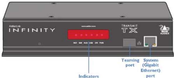
These six indicators clearly show the key aspects of operation:
• NET On when valid network link is present.
- SER On when the AUX (serial) port is enabled and active.
• AUD On when audio is enabled and active.
• USB On when the USB link with the connected PC is active.
• DVI On when a video input signal from the PC is detected.
• PWR Power indicator.
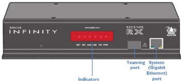
These six indicators clearly show the key aspects of operation:
• NET On when valid network link is present
- SER On when the AUX (serial) port is enabled and active.
• AUD On when audio is enabled and active.
- USB On when USB is enabled and active.
• DVI On when DVI video is enabled and active.
• PWR Power indicator.
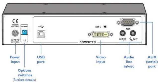
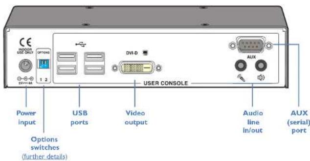
ALIF 1002 receiver - rearALIF 1002 transmitter - rear

ADDERLINK INFINITY DUAL UNIT FEATURES
The ALIF dual units are housed within durable, metallic enclosures with most connectors situated at the rear panel - the Ethernet ports are situated on the front panels. The smart front faces also feature the operation indicators.
ALIF dual (2002 and 2020) transmitter - front ALIF dual (2000 and 2020) receiver - front
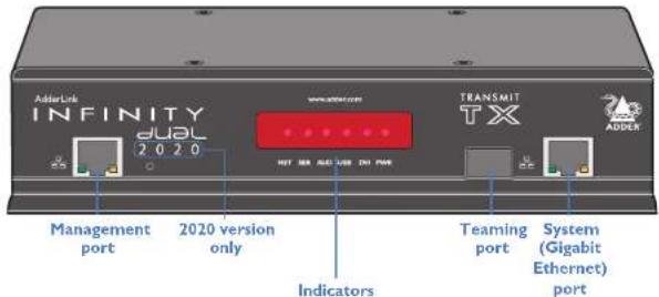
These six indicators clearly show the key aspects of operation:
• NET On when valid network link is present.
- SER On when the AUX (serial) port is enabled and active.
• AUD On when audio is enabled and active.
• USB On when the USB link with the connected PC is active.
• DVI On when a video input signal from the PC is detected.
• PWR Power indicator.
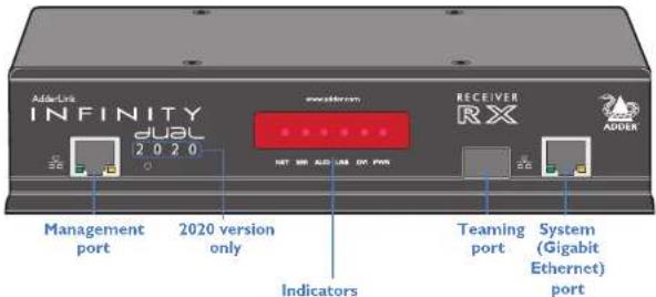
These six indicators clearly show the key aspects of operation:
• NET On when valid network link is present
- SER On when the AUX (serial) port is enabled and active.
• AUD On when audio is enabled and active.
• USB On when USB is enabled and active.
• DVI On when DVI video is enabled and active.
• PWR Power indicator.
ALIF dual (2002 and 2020) transmitter - rear
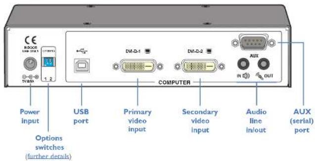
ALIF dual (2000 and 2020) receiver - rear


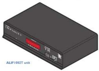
ALIF transmitter (1002T) package
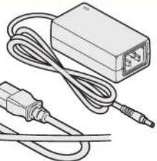
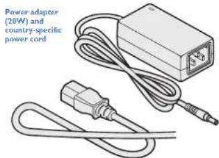
Power adaptor (20W) and country-specific power cord
Information wallet containing:
r self-adhesive rubber feet
Quick start guide:
Safety document
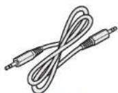
Audio cable 2m (3.5mm stereo jacks)
ALIF receiver (1002R) package
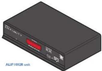
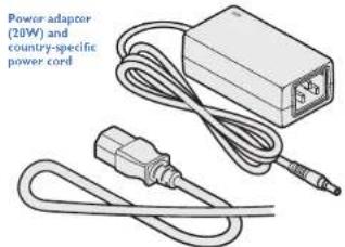
Information wallet containing: Four self-adhesive rubber feet Quick start guide Safety document

ALIF dual transmitter (2002T/2020T) package
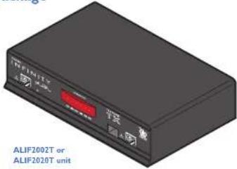
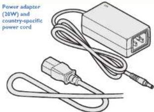
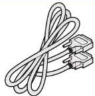
Single link DVI-D to DVI-D video cable

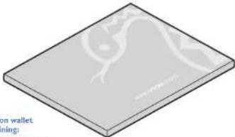
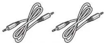
2 x Audio cable 2m (3.5mm stereo jacks)
ALIF dual receiver (2000R/2020R) package
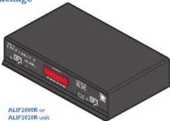
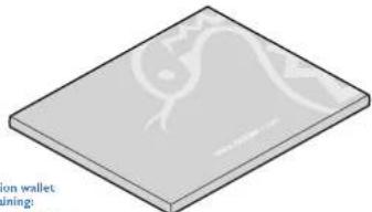
OPTIONAL EXTRAS
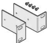
Single unit 19" rack-mount brackets plus four screws
Part number: RMK45
Single mode fiber SFP module
Part number: SFP-SM-LC
Please refer to the table in Appendix E for information about fiber modules and cables.
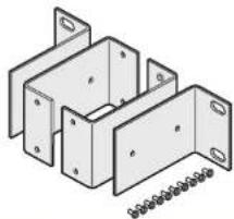
Double unit 19" rack-mount brackets plus ten screws Part number: RMI4D
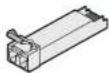
Multi mode fiber SFP module
Part number: SFP-MM-LC
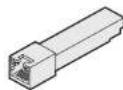
Active copper SFP module
Part number: SFP-CATX-RJ45
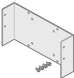
VESA mount bracket plus four screws Part number: RMK4V
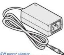
20W power adapter Part number: PSU-IEC-SVDC-4AMP
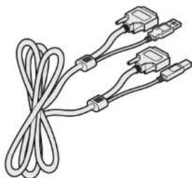
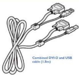
Combined dual link DVI-D and USB (USB type A to B) cable Part numbers: VSCD3 (1.8m length) VSCD4 (5m length)
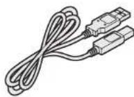
USB cable 2m (type A to B)
Part number: VSC24
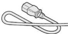
Country-specific power cords
CAB-IEC-AUS (Australia)
CAB-IEC-EURO (Central Europe)
CAB-IEC-LUK (United Kingdom)
CAB-IEC-USA (United States)
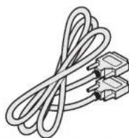
Single link DVI-D to DVI-D video cable
Part number: VSCD1
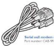
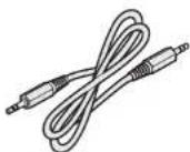
Audio cable 2m (3.5mm stereo jacks) Part number: VSC22

Installation
CONNECTIONS
Installation involves linking the ALIF TX unit to various ports on the host computer, while the ALIF RX unit is attached to your peripherals:
MOUNTING
Please see Appendix H for details about mounting options for the ALIF units.
![graph TD A["ALIF TX"] --> B["VIDEO LINK page 11"] A --> C["MANAGEMENT PORT LINK page 15"] A --> D["MANAGEMENT PORT LINK page 15"] A --> E["VIDEO DISPLAY page 16"] A --> F["MIC & SPEAKERS page 17"] A --> G["USB LINK page 12"] A --> H["SERIAL LINK page 13"] A --> I["POWER IN page 13"] A --> J["TEAMING…](/content/2026/05/810830/images/630c935fc859097bb23b11c8979a20732418e764b4416fcdfe951223e31b90a4.jpg)
Click a connection to see details
IMPORTANT: When using an AdderLink Infinity Management box to configure ALIF units, it is vital that all ALIF units that you wish to locate and control are set to their factory default settings. Otherwise they will not be located by the A.I.M. server. If necessary, perform a factory reset on each ALIF unit. Please also see Appendix C - Tips for success when networking ALIF units
TX video link
Standard ALIF (1002) units support one Single Link video display at pixel clocks up to 165MHz (equivalent to a maximum resolution of 1920 x 1200 at 60Hz).
All ALIF dual units can simultaneously support up to two Single Link high resolution video displays at pixel clocks up to 165MHz (1920 x 1200 at 60Hz maximum). ALIF2002 units can
alternatively support a single Dual Link very high Resolution video display at pixel clocks up to 330MHz (equating to an example display mode of 2560 x 1600 at 60Hz).
![graph TD A["VIDEO LINK"] --> B["ALIF TX"] C["MGMT PORT"] --> B D["AUDIO LINKS"] --> B E["USB LINK"] --> B F["SERIAL LINK"] --> B G["POWER IN"] --> B H["INFINITY RX"] --> I["LINKS"] I --> B](/content/2026/05/810830/images/778bc7ffdc47c1a4ff917cb0b9d51ba5f20466e3738b0122706331f6aec4896d.jpg)
To make a video link
I Wherever possible, ensure that power is disconnected from the ALIF and the host computer.
2 Connect your digital video link cable(s) to the DVI-D socket(s) on the TX unit rear panel:
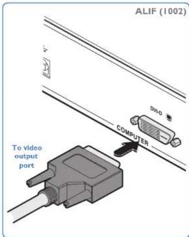
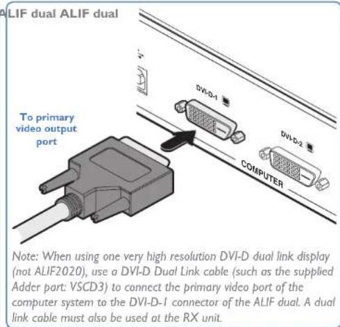
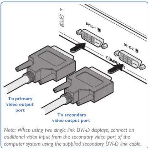
3 Connect the plug at the other end of the cable(s) to the corresponding DVI-D video output socket(s) of the host computer.
TX audio links
ALIF (1002) and ALIF dual units support two way stereo digital sound so that you can use a remote microphone as well as speakers.
![graph TD A["ALIF TX"] --> B["VIDEO LINK"] A --> C["MGMT PORT"] A --> D["USB LINK"] A --> E["SERIAL LINK"] A --> F["POWER IN"] A --> G["INFINITY RX"] B --> H["LINKS"] C --> H D --> H E --> H F --> H G --> H H --> I["INFINITY RX"]](/content/2026/05/810830/images/6da10de27bad30f006b8ee537ff50561096fc53694907806c7f7390a1a828ae2.jpg)
To make audio links
Connect an audio link cable between the in (i) socket on the TX unit rear panel and the speaker output socket of the host computer.
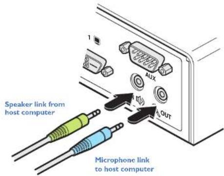
2 [Where a microphone is to be used]: Connect a second audio link cable between the OUT socket on the TX unit rear panel and the Line In socket of the host computer.
TX USB link
ALIF (1002) and ALIF dual units act as USB 2.0 hubs and so can provide four sockets at the RX unit with only a single connection at the TX unit.
![graph TD A["USB LINK"] --> B["ALIF TX"] C["SERIAL LINK"] --> B D["AUDIO LINKS"] --> B E["VIDEO LINK"] --> B F["MGMT PORT"] --> B G["POWER IN"] --> B H["LINKS"] --> I["INFINITY RX"] B --> J["LINKS"]](/content/2026/05/810830/images/4bbe037e70af20049b7850a9feca01127b2bd594783a89e0032c9a191118e7d9.jpg)
To make a USB link
Connect the type B connector of the supplied USB cable to the USB port on the TX unit rear panel.
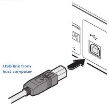
2 Connect the type A connector of the cable to a vacant USB socket on the host computer.
TX AUX (serial) port
The AUX port is an RS232 serial port that allows extension of RS232 signals up to a baud rate of 115200. The port has software flow control, but no hardware flow control.
![graph TD A["ALIF TX"] --> B["VIDEO LINK"] A --> C["MGMT PORT"] A --> D["USB LINK"] A --> E["AUDIO LINKS"] A --> F["POWER IN"] A --> G["INFINITY RX"] A --> H["SERIAL LINK"]](/content/2026/05/810830/images/92b91f818feefeaea71ed5adda6589c876aba8379ba1edbbe449b63337991ed3.jpg)
To connect the AUX port
Connect a suitable serial 'null-modem' cable (see Appendix F for pin-out) between a vacant serial port on your computer and the AUX port on the right hand side of the ALIF rear panel.
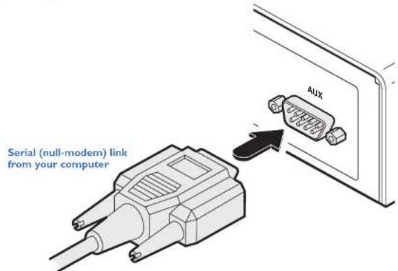
TX power in
Each ALIF unit is supplied with a power adapter and country-specific power cord. When all other connections have been made, connect and switch on the power adapter unit.
![graph TD A["ALIF TX"] --> B["VIDEO LINK"] A --> C["MGMT PORT"] A --> D["AUDIO LINKS"] A --> E["USB LINK"] A --> F["SERIAL LINK"] A --> G["POWER IN"] A --> H["LINKS"] A --> I["INFINITY RX"]](/content/2026/05/810830/images/a6cc196995c9450bf4cde6eaa537631ba0d0c8010b86e52e74e580cb3f57df1f.jpg)
To apply power in
1 Attach the output lead from the power adapter to the 5V socket on the rear panel of the unit.
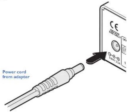
Note: Ensure that Options switches 1 and 2 are both in the 'OFF' (up) position to enable normal operation of the unit. See Options switches for details.
2 Connect the IEC connector of the supplied country-specific power cord to the socket of the power adapter.
3 Connect the power cord to a nearby main supply socket.
Note: Both the unit and its power supply generate heat when in operation and will become warm to the touch. Do not enclose them or place them in locations where air cannot circulate to cool the equipment. Do not operate the equipment in ambient temperatures exceeding 40°C. Do not place the products in contact with equipment whose surface temperature exceeds 40°C.
TX/RX high speed links
ALIF (1002) and ALIF dual units can be either connected directly to each other or via a high speed network. The connections can be copper-based Gigabit Ethernet as well as Fiber Channel over Ethernet (FCoE). These can be used in parallel to provide up to 2 Gigabit connections speeds.
A single System port (Gigabit Ethernet) is provided as standard on the right side of the front panel. Additionally, the Teaming port, located just to the left, allows you to insert either an optional Fiber Channel SFP module or Active Copper SFP module. The chosen module can then allow either a fiber optic or additional Gigabit Ethernet link to be used in parallel with the fixed System (Gigabit Ethernet) port.
To link ALIF dual units using the Teaming port
I Insert the appropriate optional SFP module (SFP-MM-LC, SFP-SM-LC or SFP-CATX-RJ45) into the aperture on the ALIF front panel:
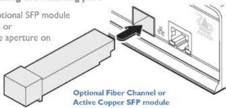
2 Make your connection(s) between the chosen SFP module and either the other ALIF unit or a suitable network switch:
Connect the transmit and receive fiber optic links to the sockets on the Fiber Channel SFP module. Then close the latch over the link connectors to lock them into place.
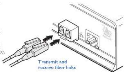
or
Connect a CAT 5, 5e, 6, or 7 cable to the socket on the Active Copper SFP module.
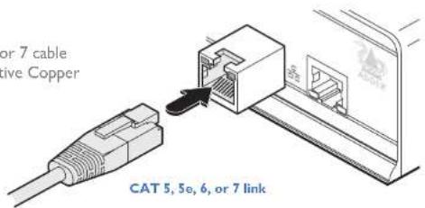
![graph LR A["ALIF TX"] --> B["LINKS"] A --> C["ALIF RX"] A --> D["AUDIO LINKS"] A --> E["USB LINK"] A --> F["SERIAL LINK"] A --> G["POWER IN"] A --> H["MGMT PORT"] A --> I["MGMT PORT"] A --> J["VIDEO DISPLAY"] A --> K["MIC & SPEAKERS"] A --> L["USB DEVICES"] A --> M["SERIAL LINK"]](/content/2026/05/810830/images/b2fc814f76fe1c7dff3000c45556d5b7de62d3dad40fa48184895348dc1d9741.jpg)
Please see Appendix C for important tips about networking ALIF units.
To link ALIF units using the System port
Connect a CAT 5, 5e, 6, or 7 cable to the System port socket on the front panel of the ALIF unit.
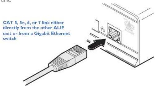
2 Connect the other end of the cable either to the other ALIF unit or to a Gigabit Ethernet switch, as appropriate.
3 [For connections via a network] repeat steps 1 and 2 for the other ALIF unit.
Cable and fiber details
- For direct links over Ethernet cable, the length of cable should not exceed 100 metres (328 feet). Network cables used for connections may be category 5, 5e, 6 or 7 twisted-pair cable. ALIF TX units have an autosensing capability on their network interfaces, so for direct point-to-point connections, no 'crossover' Ethernet cable is required.
- For direct links via fiber, varying distances can be achieved depending on the module and cable types used. Please refer to the table in Appendix G for detailed information. The fiber links must have crossovers.
TX/RX Management port (ALIF dual units only)
The Management port on each ALIF dual unit provides a consistent method to gain access to the internal configuration utility of each ALIF dual. Although the configuration utility is accessible via the System (Gigabit Ethernet) port and also the Teaming port; if the ALIF dual units are being used in a point-to-point arrangement, then it would be necessary to temporarily reconnect each unit to a network in order to make configuration changes. The Management port allows the admin user to simply connect a computer directly to each ALIF dual unit and access the configuration utility using a consistent IP address - thus negating the need to know the main port addresses of each ALIF dual unit in advance.
To connect a computer to access the configuration utility
Connect a CAT 5, 5e, 6, or 7 link cable to the Management port socket located on the far left side of the ALIF dual front panel. The port automatically configures itself, so no cross-over cable is required (but is supported if you do use one).
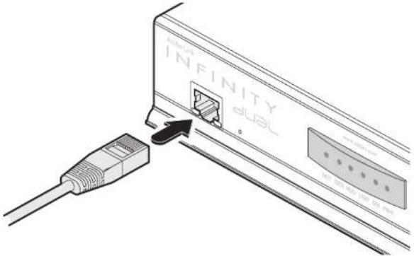
2 Connect the other end of the link cable directly to the network port of your computer.
3 Use a web browser to gain access to the internal configuration utility. The standard IP address of the Management port is 192.168.1.42
Note: This standard IP address can be changed within the configuration utility.
Please see the section AdderLink Infinity browser-based configuration utility for further details.
![graph LR A["ALIF TX"] -->|LINKS| B["ALIF RX"] A --> C["VIDEO LINK"] A --> D["AUDIO LINKS"] A --> E["USB LINK"] A --> F["SERIAL LINK"] A --> G["POWER IN"] B --> H["VIDEO DISPLAY"] B --> I["MGMT PORT"] B --> J["VIDEO LINK"] B --> K["MEMS"] B --> L["MEMS"] B --> M["MEMS"] B --> N["MEMS"] B --> O["MEMS"…](/content/2026/05/810830/images/7b52bb592cbcbfbac9a7ff47850d3eee8191f67e3d49fa56b08ccdfa5311adc9.jpg)

RX video display
Standard ALIF (1002) units support one Single Link video display at pixel clocks up to 165MHz (equivalent to a maximum resolution of 1920 x 1200 at 60Hz).
All ALIF dual units can simultaneously support up to two Single Link high resolution video displays at pixel clocks up to 165MHz (1920 x 1200 at 60Hz maximum). ALIF2000 units can
alternatively support a single Dual Link very high Resolution video display at pixel clocks up to 330MHz (equating to an example display mode of 2560 x 1600 at 60Hz).
![graph TD A["VIDEO DISPLAY"] --> B["ALIF RX"] C["INFINITY TX"] --> B D["LINKS"] --> B E["MIC & SPEAKERS"] --> B F["USB DEVICES"] --> B G["SERIAL LINK"] --> B H["MGMT PORT"] --> B I["POWER IN"] --> B](/content/2026/05/810830/images/1f48ecda270942f66fcaf72d1efd6f1339f3a53458e0bc83b67371e36c422e50.jpg)
To connect video displays
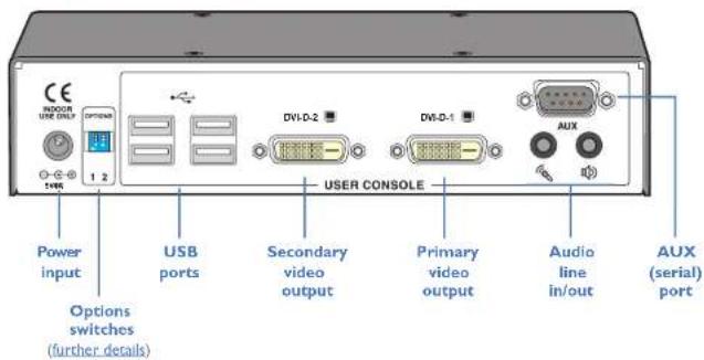
Connect the lead from the primary video display to the DVI-D-1 (DVI-D on ALIF 1002 models) socket on the RX unit rear panel:
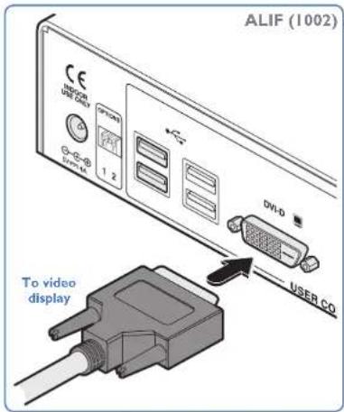
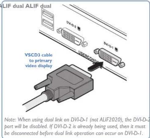
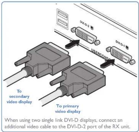
2 (ALIF dual only) If required, connect the lead from the second video display to the DVI-D-2 socket on the RX unit rear panel.
RX microphone & speakers
ALIF units can support a microphone as well as speakers providing the necessary connections have been made between the ALIF TX unit and the host computer.
![graph TD A["INFINITY TX"] --> B["ALIF RX"] C["LINKS"] --> B B --> D["VIDEO DISPLAY"] B --> E["MIC & SPEAKERS"] B --> F["USB DEVICES"] B --> G["SERIAL LINK"] B --> H["POWER IN"] B --> I["MGMT PORT"]](/content/2026/05/810830/images/bb273a224c2a53c715ea570b98c1a0d055a0a4fc40af2292f53263c9ce539060.jpg)
To connect a microphone (or line in) and/or speakers
Connect the lead from a mono microphone to the 3.5mm socket labeled "on the rear panel.
2 Connect the lead from stereo speakers to the 3.5mm socket labeled on the rear panel.
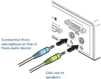
3 Once the unit has been fully connected and powered on, access the RX System Configuration page to check that the Audio Input Type setting matches the connection that you have made to the port: line, mic or mic boost (the latter provides +20dB gain).
RX USB devices
The ALIF RX unit has four USB ports to which peripherals may be connected. The ports are interchangeable. To connect more than four peripherals, one or more USB hubs may be used. The total current that may be drawn from the USB ports is 1.2A, which should be sufficient for a keyboard, mouse (no more than 100mA each) and any two other devices (500mA maximum each). If more power for USB devices is required, USB hub.
![graph TD A["INFIN/TY TX"] --> B["ALIF RX"] C["LINKS"] --> B B --> D["VIDEO DISPLAY"] B --> E["MIC & SPEAKERS"] B --> F["USB DEVICES"] B --> G["SERIAL LINK"] B --> H["POWER IN"] B --> I["MGMT PORT"]](/content/2026/05/810830/images/0005af4526a313d0e06352d829ef8c78edfe5868f5bab84fa8915e2b58625a19.jpg)
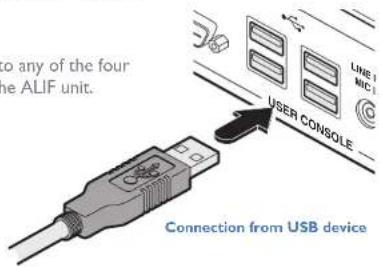
To connect a USB device
Connect the lead from the device to any of the four USB sockets on the rear panel of the ALIF unit.
Supported USB Devices
The transmitter unit uses True Emulation technology to emulate the signals of certain USB peripherals to the computer. This means that those peripherals appear to the computer to be permanently connected, even when the receivers are switched elsewhere. This enables faster keyboard and mouse switching and allows for more than 13 identical USB devices. If the keyboards and mice are identical across the connected receivers, they are only enumerated once by the host. The following limitations apply:
• Keyboards, mice and other HID devices are supported.
- Storage devices (i.e. flash drives, USB hard disks, CD-ROM drives) are supported, but they may operate more slowly than with a direct connection.
- Isochronous devices (including microphones, speakers, webcams and TV receivers) are not currently supported.
- Many other devices (such as printers, scanners, serial adapters and specialist USB devices) will work, but due to the huge variety of devices available, successful operation cannot be guaranteed.
- If a device cannot be made to work, please contact Adder technical support as a special entry within the advanced configuration may solve it.
RX AUX (serial) port
The AUX port is an RS232 serial port that allows extension of RS232 signals up to a baud rate of 115200. The port has software flow control, but no hardware flow control.
![graph TD A["ALIF RX"] --> B["INFINITY TX"] A --> C["LINKS"] A --> D["VIDEO DISPLAY"] A --> E["MIC & SPEAKERS"] A --> F["USB DEVICES"] A --> G["SERIAL LINK"] A --> H["MGMT PORT"] A --> I["POWER IN"]](/content/2026/05/810830/images/41b13d883e4bc84955c220393b6e8719d9b7ce6ffe54f94f0bc52292f662fbab.jpg)
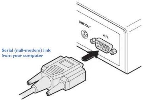
To connect the AUX port
Connect a suitable serial 'null-modem' cable (see Appendix F for pin-out) between the AUX port on the right hand side of the ALIF rear panel and your remote serial device.
RX power in
Each ALIF unit is supplied with an appropriate power adapter. When all other connections have been made, connect and switch on the power adapter unit.
![graph TD A["ALIF RX"] --> B["INFINITY TX"] A --> C["LINKS"] A --> D["VIDEO DISPLAY"] A --> E["MIC & SPEAKERS"] A --> F["USB DEVICES"] A --> G["SERIAL LINK"] A --> H["POWER IN"] H --> I["MGMT PORT"]](/content/2026/05/810830/images/1d2c7a24f07c5865e765b193ef322ad59fbdce7ac036b7fd3e2958dfb971618a.jpg)
To apply power in
1 Attach the output lead from the power adapter to the 5V socket on the rear panel of the unit.
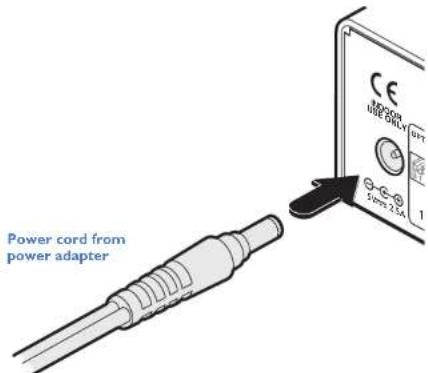
Note: Ensure that Options switches 1 and 2 are both in the 'OFF' (up) position to enable normal operation of the unit. See Options switches for details.
2 Connect the IEC connector of the supplied country-specific power cord to the socket of the power adapter.
3 Connect the power cord to a nearby main supply socket.
Note: Both the unit and its power supply generate heat when in operation and will become warm to the touch. Do not enclose them or place them in locations where air cannot circulate to cool the equipment. Do not operate the equipment in ambient temperatures exceeding 40°C. Do not place the products in contact with equipment whose surface temperature exceeds 40°C.
Configuration
ALIF units are designed to be as flexible as possible and this principle extends also to their configuration.
Direct linking
Where ALIF transmitters and receivers are directly linked to each other, very little configuration action is required, provided that they have their factory default settings in place. If the standard settings have been changed in a previous installation, you merely need to perform a factory reset on each unit.
Networked linking
Where ALIF units are connected via networked links, you can either configure them individually, or configure them collectively using an A.I.M. server:
- Configuring networked ALIF units individually - You need to specify the network addresses of the ALIF units so that they can locate each other. This is done by running the AdderLink Infinity browser-based configuration utility on a computer system linked to the same network as the ALIF units.
- Configuring ALIF units collectively - The AdderLink Infinity Management (A.I.M.) server allows you to configure, control and coordinate any number of ALIF transmitters and receivers from a single application.
IMPORTANT: When using A.I.M. to configure ALIF units, it is vital that all units that you wish to locate and control are set to their factory default settings. Otherwise they will not be located by the A.I.M. server. If necessary, perform a factory reset on each ALIF unit.
Please also see Appendix C - Tips for success when networking ALIF units
Note: Please read the important advice in the section Firmware version 3.3 (or greater) before attempting installation or upgrades.
Manual factory reset
A factory reset returns an ALIF TX or RX unit to its default configuration. You can perform factory resets using the AdderLink Infinity browser-based configuration utility or by using this direct manual method.
To perform a manual factory reset
I Remove power from the ALIF unit.
2 Use a narrow implement (e.g. a straightened-out paper clip) to press-and-hold the recessed reset button on the front panel. With the reset button still pressed, reapply power to the unit and then release the reset button.
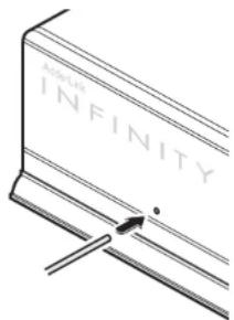
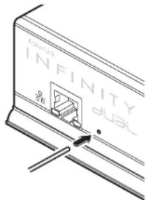
Use a straightened-out paper clip to press the reset button while powering on the unit
After roughly eight seconds, when the factory reset has completed, five of the front panel indicators will flash for a period of three seconds to indicate a successful reset operation.
AdderLink Infinity browser-based configuration utility
The browser-based configuration utility within all TX and RX units requires a network connection between the ALIF unit and a computer on the same network. The configuration utility allows you to perform many important functions. Please see Appendix A for TX unit details and Appendix B for RX unit details.
It is possible to gain access to the internal configuration utility via any of the ports located on the front panel of each ALIF dual unit. For temporary connections on ALIF dual units, you are recommended to use the Management port. There is no Management port on ALIF 1002 models, so use the System port instead.
To connect a computer to access the configuration utility
1 Connect a CAT 5, 5e, 6, or 7 link cable to either the Management (ALIF dual only) or System port socket on the front panel. The port automatically configures itself, so no cross-over cable is required (but is supported if you do use one).
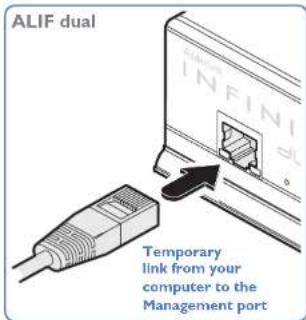
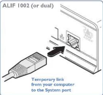
2 Connect the other end of the link cable directly to the network port of your computer.
To access the browser-based configuration utility
I Temporarily connect the ALIF unit and your computer, as discussed left.
2 Run a web browser on your computer and enter the IP address of the ALIF port that you are using.
The default settings are as follows:
| TX units RX units | ||
| Management port | 192.168.1.42 | 192.168.1.42 |
| System port | 169.254.1.33 | 169.254.1.32 |
| Teaming port | 169.254.1.43 | 169.254.1.42 |
Note: Where the port addresses of a unit have been changed and are not known, providing it is appropriate to do so, perform a manual factory reset to restore the default addresses.
The opening page of the ALIF configuration utility should be displayed:
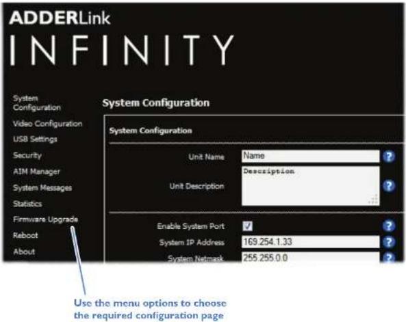
You can find further information about the configuration pages for the TX and RX units within separate appendices later in this guide:
- Appendix A - Transmitter (TX) unit configuration pages
- Appendix B - Reciever (RX) unit configuration pages
PERFORMING AN UPGRADE
ALIF units are flash upgradeable using the method outlined here. However, for larger installations we recommend that you use the AdderLink Infinity Manager (A.I.M.) to upgrade multiple ALIF units. When using the method below, the ALIF unit will be upgraded in sequence.
IMPORTANT: Upgrades must be performed on both the transmitters and the receivers at the same time. Mixed firmware operation is not supported.
WARNING: During the upgrade process, ensure that power is not interrupted as this may leave the unit in an inoperable state.
If the upgrade process is interrupted and fails, it may be necessary to switch to the backup firmware image in order to regain operation. See right for details.
To upgrade a single unit via network link
I Download the latest upgrade file from the Adder Technology website. Note: There are separate upgrade files for TX and RX units.
2 Temporarily connect the ALIF unit and a computer via a network (see AdderLink Infinity browser-based configuration utility section for details).
3 Run a web browser on your computer and enter the IP address of the ALIF unit to be upgraded.
4 Click the Firmware Upgrade link. Within the Firmware Upgrade page, click the Choose File button. In the subsequent file dialog, locate the downloaded upgrade file - check that the file is correct for the unit being upgraded. The file contains main and backup images, you can choose to upgrade either the Main or the Backup.
5 Click the Upgrade Now button. A progress bar will be displayed (however, if your screen is connected to the unit being upgraded then video may be interrupted) and the indicators on the front panel will flash while the upgrade is in progress.
6 The indicators should stop flashing in less than one minute, after which the unit will automatically reboot itself. The upgrade process is complete.
Finding the latest upgrade files
Firmware files for the ALIF units are available from the Technical Support > Updates section of the Adder Technology website (www.adder.com).
Note: It is possible to downgrade the AdderLink Infinity firmware. After installing the older firmware, perform a factory reset on each AdderLink Infinity in order to clear the configuration file.
Note: If you have an ALIF unit at v3.3 or higher, and you wish to downgrade its firmware via A.I.M. v2.5 to v2.9 (so as to use it within an A.I.M. v2.5 system), this can only be done via the copper interface and not the fiber interface.
Note: Please read the important advice in the section Firmware version 3.3 (or greater) before attempting installation or upgrades.
OPTIONS SWITCHES
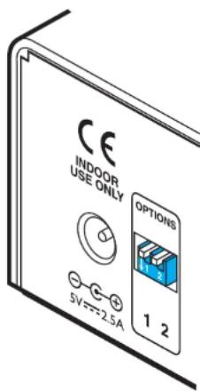
A pair of Options switches are located on the rear panel of every ALIF unit.
Switch I - firmware image select
Each ALIF unit retains a backup firmware image which can be used in situations where the primary firmware becomes corrupted (most often through failed upgrade operations). Using the backup firmware will allow you to regain operation of the unit.
Option switch I OFF Normal operation using the main firmware ON Operate using the backup firmware image
Option switch 2 is reserved and must remain in the OFF (up) position for normal operation.
Operation
In operation, many ALIF installations require no intervention once configured. The TX and RX units take care of all connection control behind the scenes so that you can continue to work unhindered.
FRONT PANEL INDICATORS
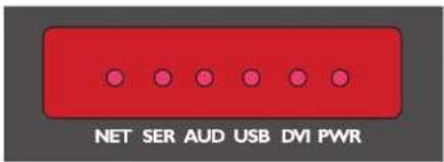
The six front panel indicators on each unit provide a useful guide to operation:
Indicators
These six indicators clearly show the key aspects of operation:
• NET On when valid network link is present.
- SER On when the AUX (serial) port is enabled and active.
• AUD On when audio is enabled and active.
- USB On when USB is enabled and active.
• DVI On when the DVI Video channel is enabled and active.
• PWR Power indicator.

INSTALLATIONCONFIGURATION

FURTHER INFORMATION
INDEX
Further information
This chapter contains a variety of information, including the following:
• Getting assistance - see right
- Appendix A - Transmitter (TX) unit configuration pages
- Appendix B - Receiver (TX) unit configuration pages
- Appendix C - Tips for success when networking ALIF units
• Appendix D - Troubleshooting
- Appendix E - Glossary
- Appendix F - RS232 'null-modem' cable, General specifications.
• Appendix G - Fiber modules and cables
- Appendix H - Mounting options
• Safety information
- Warranty
• Radio frequency energy statements
GETTING ASSISTANCE
If you are still experiencing problems after checking the information contained within this guide, then we provide a number of other solutions:
• Online solutions and updates – www.adder.com/support
Check the Support section of the adder.com website for the latest solutions and firmware updates.
- Adder Forum – forum.adder.com
Use our forum to access FAQs and discussions.
• Technical support – www.adder.com/contact-support-form
For technical support, use the contact form in the Support section of the adder.com website - your regional office will then get in contact with you.

APPENDIX A - Transmitter (TX) unit configuration pages
This section covers the browser-based configuration utility for the AdderLink Infinity TX (transmitter) unit. The TX utility has ten pages, titled as follows:
- System Configuration • System Messages
• Video Configuration • Statistics - USB Settings • Firmware Upgrade
• Security • Reboot ____
• AIM Manager • About

TX System Configuration
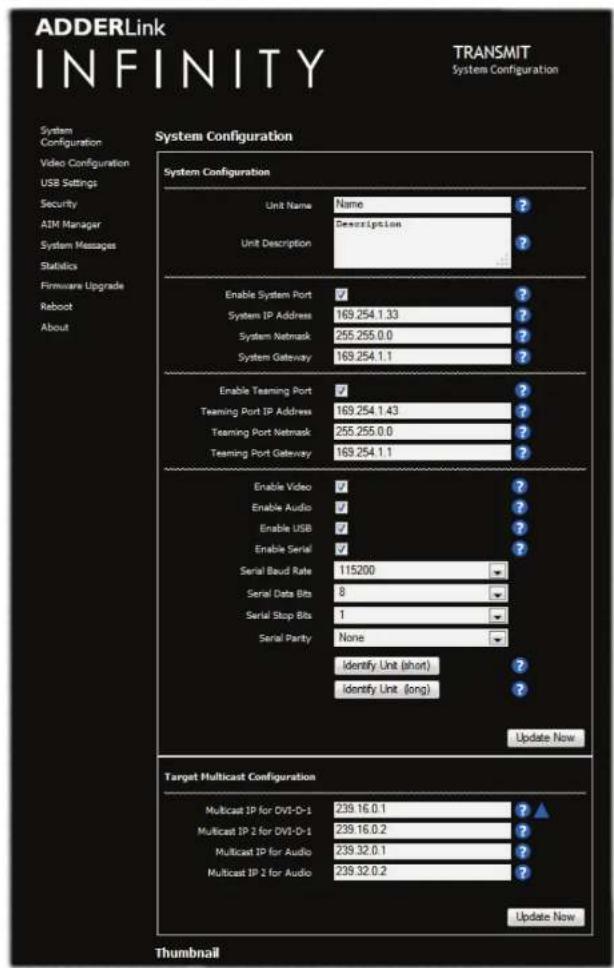
Unit Name
Name details that you can alter to distinguish this unit from all others. The name entered here will be read by A.I.M. units (if used) for administration purposes.
Unit Description
Allows you to optionally add a description of the unit, such as its location. Useful when many ALIF units are being used.
System port
This section determines the IP address, netmask and gateway details for the main Gigabit Ethernet port located on the right side of the front panel. The default IP address is 169.254.1.33 which is the zero config IP address that allows the unit to work immediately in point-to-point mode. You are recommended to change this to an appropriate address in the private IP range 192.168.xxx.xxx
The default netmask is 255.255.0.0. If you change the IP address to the private range, you are recommended to change this to 255.255.255.0 The default gateway address is 169.254.1.1
Management port (ALIF dual models only - not shown in screenshot left)
Determines whether the port on the left side of the front panel is enabled and which IP address details it should use. The default IP address is 192.168.142. You are recommended to leave this address unchanged (or at least keep such addresses constant across all of your ALIF dual units) so that all visiting engineers will know which address to use.
Teaming port
Determines whether the SFP socket on the right side of the front panel is enabled and which IP address details it should use. The default IP address is 169.254.1.43 which is the zero config IP address that allows the unit to work immediately in point-to-point mode. You are recommended to change this to an appropriate address in the private IP range 192.168.xxx.xxx. The default netmask is 255.255.0.0. If you change the IP address to the private range, you are recommended to change this to 255.255.255.0
The default gateway address is 169.254.1.1 Note: Before the Teaming port can be used for connection via a network, you need to ensure that the System port has been configured away from its zero config IP address.
Enable options
These checkboxes allow you to determine which peripheral options will be used: Video, audio, USB and serial.
Serial port options
These allow you to match the serial configuration being used by the attached PC host.
Identify unit
When clicked, these buttons cause the front panel indicators to flash to assist with identifying the ALIF unit within a rack.
• The Identify Unit (short) button flashes the indicators for five seconds.
- The Identify Unit (long) button flashes the indicators for one hour but can be overridden by clicking the Identify Unit (short) button.
Thumbnail
The Thumbnail shows snap shots of the video feeds that are connected and reports the video resolutions/color depths that have been detected. Click the Refresh Thumbnail button to update.
Target Multicast Configuration
The items within this section are required if a multicast group is being arranged i.e. many receivers connected to the one transmitter. For the video port(s) and/or audio channel, you need to enter the multicast IP addresses. In each case, the first address relates to the System (Gigabit Ethernet) port and the second address to the optional Teaming port.
In previous revisions of firmware, the destination IP address for video was decided by the RX. If multiple RX units requested the same video source then all had to provide the same multicast destination IP address. In revision 3.3 and above, the TX now decides the destination IP address for video and automatically informs any interested RX units. In a system with a mix of new and old units, both RX and TX units must be configured with the same destination IP address for video.
Note: All multicast addresses for each service endpoint must be unique across the whole ALIF installation.
TX Video Configuration
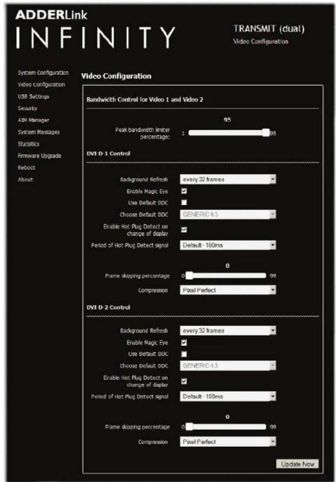
Note: ALIF dual screenshot shown above. ALIF 1002 models will provide options for a single video port.
Peak bandwidth limiter percentage
The TX unit will employ a 'best effort' strategy in sending video and other data over the IP network. This means it will use as much of the available network bandwidth as necessary to achieve optimal data quality, although typically the TX unit will use considerably less than the maximum available. In order to prevent the TX unit from 'hogging' too much of the network capacity, you can reduce this setting to place a tighter limit on the maximum bandwidth permissible to the TX unit. Range: 0 to 95%.
Note: All of the following controls are available separately for each video port:
Background Refresh
The TX unit sends portions of the video image only when they change. In order to give the best user experience, the TX unit also sends the whole video image, at a lower frame rate, in the background. The Background Refresh parameter controls the rate at which this background image is sent. The default value is 'every 32 frames', meaning that a full frame is sent in the background every 32 frames. Reducing this to 'every 64 frames' or more will reduce the amount of bandwidth that the TX unit consumes. On a high-traffic network this parameter should be reduced in this way to improve overall system performance. Options: every 32 frames, every 64 frames, every 128 frames, every 256 frames or disabled.
Enable Magic Eye
This feature, enabled as standard, aims to reduce the effect of dithering - a technique used by some graphics cards to improve the perceived quality and color depth of images by diffusing or altering the colour of pixels between video frames. The Magic Eye feature increases the frame rate and eliminates unnecessary network traffic by ignoring the color dithering where it occurs. If the video source is not noisy or dithered then you can switch off Magic Eye to enable full colour accuracy.
Use Default DDC and Choose Default DDC
When the Use Default DDC option is unticked, AdderLink Infinity will use the EDID that is reported by the monitor connected to the receiver unit. However, if you tick the Use Default DDC option, you can then select from a range of preset video resolutions from the Choose Default DDC drop down box. Once selected, the TX will report itself capable of only supporting this one video resolution. Please note that all of the listed video resolutions are single link DVI with a maximum pixel clock of 165MHz and a 60Hz refresh rate.
Enable Hot Plug Detect...
When this option is ticked, every time the monitor is changed at the receiver unit, a hot plug detect message will be sent to the graphics card of the PC attached to the TX unit.
Period of Hot Plug Detect signal
This is the length of time that a hot-plug detect signal is applied. The default of 100mS is sufficient for the majority of graphics cards, however, a small minority may need to be given a longer a period.
Frame skipping percentage
Frame Skipping involves 'missing out' video frames between those captured by the TX unit. For video sources that update only infrequently or for those that update very frequently but where high fidelity is not required, frame skipping is a good strategy for reducing the overall bandwidth consumed by the system. Range: 0 to 100%.
Compression
Determines the (AFZ and AFZ+) compression method used for video transmission. Choices are:
• 'Pixel perfect' - only uses pixel perfect AFZ,
- 'Adapive' - guarantees frame rate, builds to pixel perfect,
* 'Smoothest video' - forces the maximum compression, or
* 'Advanced' - allows you to choose a fixed compression mode:
• 'AFZ only (pixel perfect),
- 'AFZ+ Minimum compression',
• 'AFZ+ Middle compression', or
• 'AFZ+ Maximum compression'
To get here
Connect your computer to a port on the front panel.
2 Run a web browser and enter the IP address of the Management (ALIF dual only) or System port used: http://192.168.1.42 (management port) or http://169.254.1.33 (system port) If the address is unknown, perform a manual factory reset.
3 If necessary, click the Video Configuration link.

TX USB Settings
TX Security

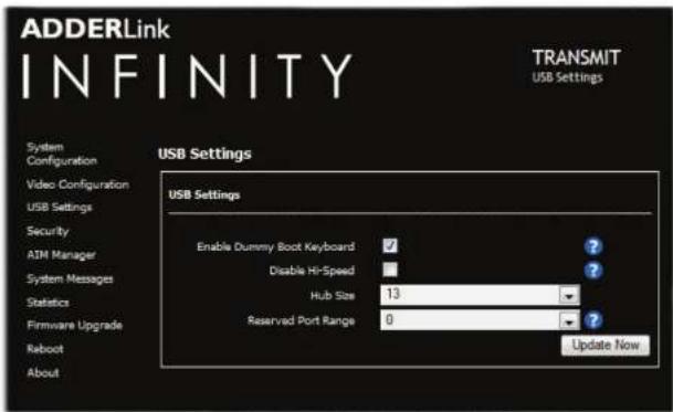
Enable Dummy Boot Keyboard
When ticked, the TX unit reports a virtual dummy boot keyboard to the attached PC to ensure that a keyboard is always reported when the PC boots up. The dummy boot keyboard uses one of the 13 USB endpoints, therefore if all 13 endpoints are required elsewhere for USB devices (or a KVM switch only supports two HID devices) then it can be disabled by deselecting this option. See also Reserved Port Range below.
Disable Hi-Speed
This option allows you to force the system to run at the low/full USB speed of 12Mb/s, thus forcing USB 2.0 Hi-Speed devices to adapt to the lower rate.
Hub Size
Using this option you can select whether the transmitter should report itself as a 13 or a 7 port USB hub. Some USB hosts are only able to support 7 port USB hubs. If this option is set to 7, then only 7 USB devices are supported by the PC.
Reserved Port Range
For some devices, e.g. touch screens, you may wish to ensure that they are always reported to the same USB port number so that the USB driver will always find the device. This option allows you reserve up to 8 ports for certain devices. At the RX unit, the devices are assigned to the reserved ports. If a port reservation is to be applied, then the dummy boot keyboard should be disabled. The default value for this option is '0', i.e. disabled. See Port Reservation on RX unit for further details.
USB Encryption
This setting determines whether encryption should be applied to the USB data passed across the link. Note that video data is never encrypted.
Control Encryption
This setting determines whether encryption should be applied to the control data passed across the link. Note that video data is never encrypted.
Secure Web pages with password
When ticked, this option enables https security so that the configuration pages are only accessible to the admin user with a password.
Change/confirm password
These options allow you to change the admin password for the system.
To get here
I Connect your computer to a port on the front panel.
2 Run a web browser and enter the IP address of the Management (ALIF dual only) or System port used: http://192.168.1.42 (management port) or http://169.254.1.33 (system port)
If the address is unknown, perform a manual factory reset.
3 Click either the USB Settings or Security links, as appropriate.

TX AIM Manager
TX System Messages
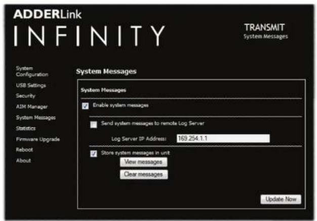
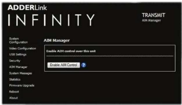
Enable AIM Control
Click this button to allow an A.I.M. (Adder Infinity Manager) box to take control of this TX. When the button is clicked, the TX unit will be rebooted to allow the A.I.M. box to discover and control it.
Enable system messages
Tick to allow the creation of status and error messages by the unit.
Send system messages to remote Log Server
Choose this option to send the system messages to a remote server via the network. Provide the IP address of a suitable server here also.
AdderLink Infinity servers use the User Datagram Protocol (UDP) for all Syslog traffic.
Store system messages in unit
When ticked, this option will store system messages within the memory of the unit. Click the View messages button to view the list or the Clear messages button to delete the list.
Update Now
Click to save and implement any changes that you make.
To get here
I Connect your computer to a port on the front panel.
2 Run a web browser and enter the IP address of the Management (ALIF dual only) or System port used: http://192.168.1.42 (management port) or http://169.254.1.33 (system port)
If the address is unknown, perform a manual factory reset.
3 Click either the AIM Manager or System Messages links, as appropriate.

TX Statistics
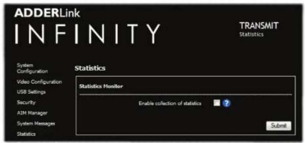
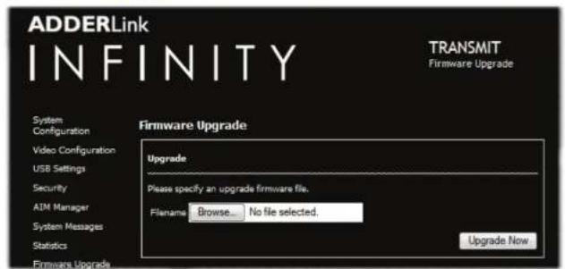
TX Firmware Upgrade
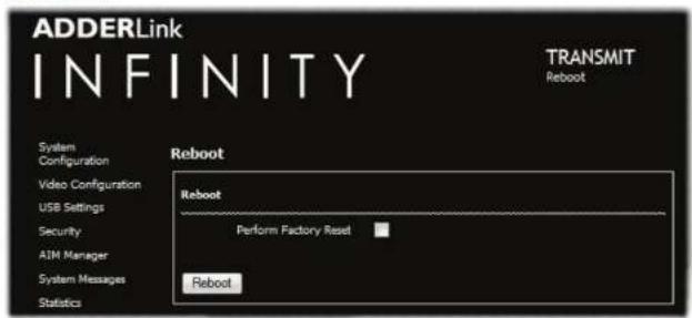
TX Reboot
Enable collection of bandwidth statistics
ALIF units can record data transfer statistics from the System port and plot them on a graph for troubleshooting and optimization purposes. When you enable this option, you will first be presented with a pop up from which you can choose which aspects you would like to graph: Data throughput, various packet rates and/or frame rates.
Submit
Click this button after ticking the above checkbox to plot the chosen statistics on a pop up graph.
Upgrade
Use this page to upgrade the main or backup firmware image on the unit. Please see the section Performing an upgrade for details.
Reboot
Use this page to perform a reboot or a factory reset. Please see the section Manual factory reset for details.
To get here
Connect your computer to a port on the front panel.
2 Run a web browser and enter the IP address of the Management (ALIF dual only) or System port used: http://192.168.1.42 (management port) or http://169.254.1.33 (system port)
If the address is unknown, perform a manual factory reset.
3 Click either the Statistics, Firmware Upgrade or Reboot links, as appropriate.

TX About
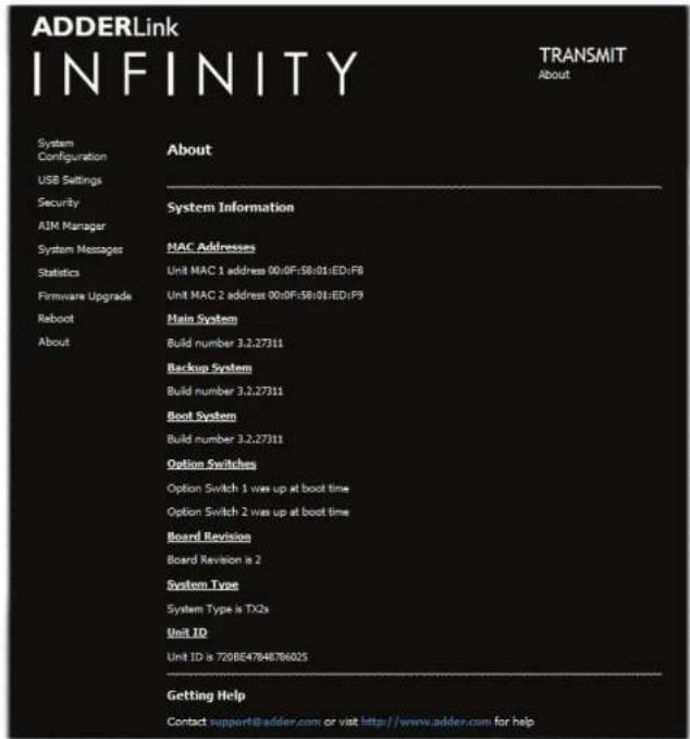
About
This page displays key information about the TX unit that may be requested by Adder Technical Support.
To get here
I Connect your computer to a port on the front panel.
2 Run a web browser and enter the IP address of the Management (ALIF dual only) or System port used: http://192.168.1.42 (management port) or http://169.254.1.33 (system port)
If the address is unknown, perform a manual factory reset.
3 Click the About link.

APPENDIX B - Receiver (RX) unit configuration pages
This section covers the browser-based configuration utility for the AdderLink Infinity RX (receiver) unit. The RX utility has nine pages, titled as follows:
- System Configuration • Statistics
• USB Settings • Firmware Upgrade - Security - Reboot
• AIM Manager • About - System Messages

RX System Configuration (1 of 2)
ADDERLink
INFINITY
RECEIVER
System Configuration
System Configuration
USB Settings
Covonity
(1)基因通过控制 通过控制
AIN Manager
System Messages
Stefinger
Egenvo-ve1-mercado
2.1.3
REDDU
About
System Configuration

Unit Name
Name details that you can alter to distinguish this unit from all others.
Unit Description
Allows you to add a description of the unit, such as its location. Useful when many ALIF units are being used.
System port
This section determines the IP address, netmask and gateway details for the main Gigabit Ethernet port located on the right side of the front panel. The default IP address is 169.254.1.32 which is the zero config IP address that allows the unit to work immediately in point-to-point mode. You are recommended to change this to an appropriate address in the private IP range 192.168.xxx.xxx
The default netmask is 255.255.0.0. If you change the IP address to the private range, you are recommended to change this to 255.255.255.0 The default gateway address is 169.254.1.1
Management port (ALIF dual models only - not shown in screenshot left)
Determines whether the port on the left side of the front panel is enabled and which IP address details it should use. The default IP address is 192.168.1.42. You are recommended to leave this address unchanged (or at least keep such addresses constant across all of your ALIF units) so that all visiting engineers will know which address to use.
Teaming port
Determines whether the SFP socket on the right side of the front panel is enabled and which IP address details it should use. The default IP address is 169.254.1.42 which is the zero config IP address that allows the unit to work immediately in point-to-point mode. You are recommended to change this to an appropriate address in the private IP range 192.168.xxx.xxx. The default netmask is 255.255.0.0. If you change the IP address to the private range, you are recommended to change this to 255.255.255.0
The default gateway address is 169.254.1.1 Note: Before the Teaming port can be used for connection via a network, you need to ensure that the System port has been configured away from its zero config IP address.
Enable options
These checkboxes allow you to determine which peripheral options will be used: Video, audio, USB and serial.
Audio Input Type
Choose 'line' for stereo line input, 'mic' for mono microphone or 'mic boost' for a mono microphone that requires extra gain (+20dB).
Enable Video Compatibility Check (for DVI-D I and 2 on ALIF dual models)
If enabled, this option compares the EDID reported by the PC graphics card and determines whether the display connected to the RX is capable of displaying the chosen video resolution. If not, an error message is generated and the connection is not made.
Force Video Refresh Rate to 60Hz
If enabled, the receiver frame rate is held at 60Hz regardless of the video input frame rate. The Video Switching options (below) cannot be altered when this option is enabled.
Video switching
Provides two options for video switching:
- Fast Switching (default state) - Retains the same frame rate (at either 50Hz or 60Hz) depending upon which video resolution was displayed first.
- Match Frame Rate - Follows the source frame rate and will change the frame rate every time this changes even if the video resolution doesn't change. If you have one receiver switching between 1920x1080@60Hz and
1920x1080@50Hz then this setting will change the frame rate from 60Hz to 50 Hz every time that you switch.
Identify unit
These buttons cause the front panel indicators to flash. The (short) button flashes indicators for 5 seconds; the (long) button for one hour. Click the (short) button to override.
To get here
I Connect your computer to a port on the front panel.
2 Run a web browser and enter the IP address of the Management (ALIF dual only) or System port used: http://192.168.1.42 (management port) or http://169.254.1.32 (system port)
If the address is unknown, perform a manual factory reset.
3 If necessary, click the System Configuration link.

RX System Configuration (2 of 2)
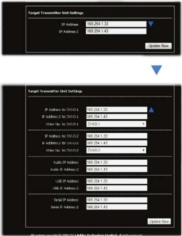
Note: ALIF dual screenshot shown above. ALIF 1002 models will provide options for a single video port only.
Target Transmitter Unit Settings
This section is where you configure the IP address details of the ALIF transmitter(s) that this receiver will connect with. You can quickly set all peripheral feeds (video 1/2, audio, USB and serial) to use the same primary (and secondary) locations using the IP Address (System port) and IP Address 2 (Teaming port) entries. For normal one-to-one connections enter the IP address(es) that match the System IP Address and Teaming Port IP Address settings of the target transmitter unit in this section. However, if this receiver is to take part in a multicast connection then you need to enter the IP address(es) that are set within the transmitter's Target Multicast Configuration section.
Alternatively, click the Arrow to expand the section as shown bottom left. In the expanded view, for each peripheral feed, the first IP address is that of the targeted TX unit's System port (to match the address(es). IP Address 2 corresponds to the optional Teaming port (when used).
The use of the Teaming port as a parallel secondary link offers a degree of redundancy for your ALIF installation. With the Teaming ports of the TX and RX units connected in addition to the System ports, if one of the links should fail for any reason, there will be a short delay for a few video frames (and possibly some on-screen corruption) as all the data packets are rearranged to be sent down the other link. Obviously the bandwidth will be halved and frame rate will automatically drop, but a fully usable system will remain.
[ALIF dual only] The Video No. for DVI-D-x option allows you to determine which video feed is sent to each output port. By default, the primary video feed is presented at port 1 while the secondary feed goes to port 2. These options allow you to 'clone' one of the video signals and deliver it to both ports - thus, requiring only one receiver to drive two displays. This solution is commonly used where two signage displays are mounted back-to-back and need to show the same video feed. With these options, you can also swap the two video feeds between the two ports.
To get here
Connect your computer to a port on the front panel.
2 Run a web browser and enter the IP address of the Management (ALIF dual only) or System port used: http://192.168.1.42 (management port) or http://169.254.1.32 (system port)
If the address is unknown, perform a manual factory reset
3 If necessary, click the System Configuration link.
4 Click ▼ within the Target Transmitter Unit Settings section.

RX USB Settings
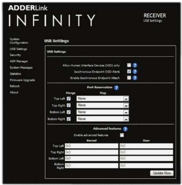
Allow Human Interface Devices (HID) only
When enabled, this option restricts supported USB devices to keyboards and mice only. The use of memory sticks and other devices will be disabled.
Isochronous Endpoint OSD Alerts
The ALIF USB system does not support Isochronous USB. When enabled, this option will alert the user when an Isochronous USB device is connected.
Enable Isochronous Endpoint Attach
When enabled, this option will allow for an exchange of control information with an isochronous device. Some devices have multiple endpoints e.g. a keyboard with an audio controller. By enabling this option, the keyboard functionality will work even though the isochronous audio functionality will not. Without this setting, the entire keyboard would be rejected as it would be detected as being solely an isochronous device.
Port Reservation
This section allows you map the four USB connectors on the receiver to a specific USB port that has been reserved on the transmitter. It is useful if you have a specific device e.g. a touch screen that must allows be reported to a specific USB port on the USB host device. If you have two touch screens of the same type for each of the video displays, then using Port Reservation disables the USB merging mechanism and assigns individual USB ports for each display. This means that the driver can now separate the left hand screen from the right hand screen. See Reserved Port Range on the TX unit for further details.
Advanced features
This section is used for special configuration and is disabled by default. If a USB device fails to operate as expected, this section allows special codes to be inserted to attempt to solve the issue.
To get here
Connect your computer to a port on the front panel.
2 Run a web browser and enter the IP address of the Management (ALIF dual only) or System port used: http://192.168.1.42 (management port) or http://169.254.1.32 (system port)
if the address is unknown, perform a manual factory reset
3 Click the USB Settings link.

RX Security
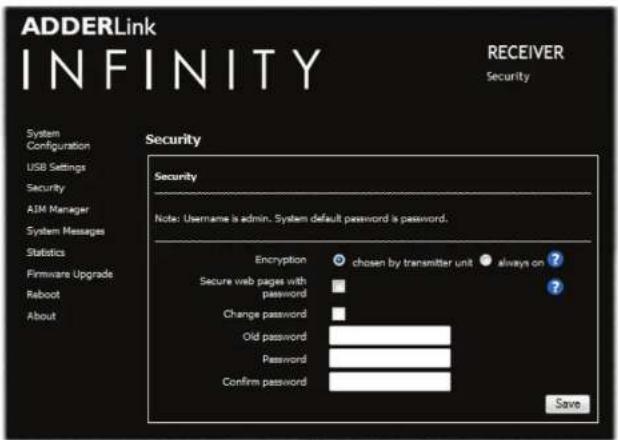
Encryption
This setting allows you to apply encryption to the USB and control data passed across the link. Note that video data is never encrypted.
Secure Web pages with password
When ticked, this option enables https security so that the configuration pages are only accessible to the admin user with a password.
Change/confirm password
These options allow you to change the admin password for the system.
To get here
I Connect your computer to a port on the front panel.
2 Run a web browser and enter the IP address of the Management (ALIF dual only) or System port used: http://192.168.1.42 (management port) or http://169.254.1.32 (system port)
If the address is unknown, perform a manual factory reset.
3 Click the Security link.

RX AIM Manager
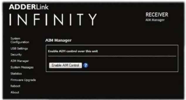
RX System Messages
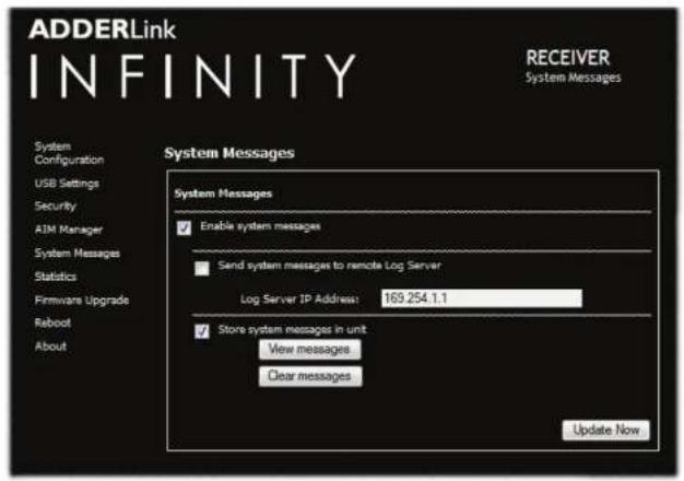
Enable AIM Control
Click this button to allow an A.I.M. (Adder Infinity Manager) box to take control of this RX. When the button is clicked, the RX unit will be rebooted to allow the A.I.M. box to discover and control it.
Enable system messages
Tick to allow the creation of status and error messages by the unit.
Send system messages to remote Log Server
Choose this option to send the system messages to a remote server via the network. Provide the IP address of a suitable server here also.
AdderLink Infinity servers use the User Datagram Protocol (UDP) for all Syslog traffic.
Store system messages in unit
When ticked, this option will store system messages within the memory of the unit. Click the View messages button to view the list or the Clear messages button to delete the list.
Update Now
Click to save and implement any changes that you make.
To get here
1 Connect your computer to a port on the front panel.
2 Run a web browser and enter the IP address of the Management (ALIF dual only) or System port used: http://192.168.1.42 (management port) or http://169.254.1.32 (system port)
If the address is unknown, perform a manual factory reset.
3 Click either the AIM Manager or System Messages links, as appropriate.

RX Statistics
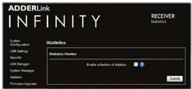
RX Firmware Upgrade
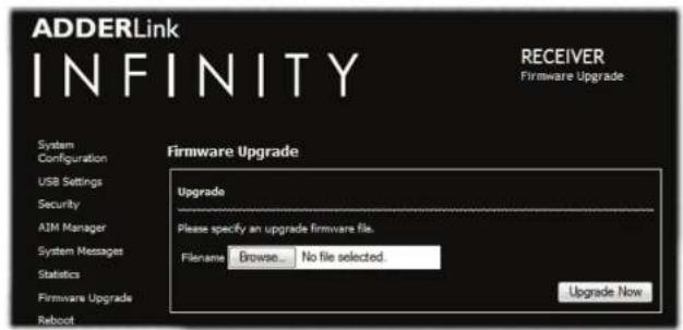
RX Reboot
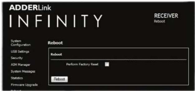
Enable collection of bandwidth statistics
The ALIF unit can record data transfer statistics from the System port and plot them on a graph for troubleshooting and optimization purposes. When you enable this option, you will first be presented with a pop up from which you can choose which aspects you would like to graph: Data throughput, various packet rates and/or frame rates.
Submit
Click this button after ticking the above checkbox to plot the chosen statistics on a pop up graph.
Upgrade
Use this page to upgrade the main or backup firmware image on the unit. Please see the section Performing an upgrade for details.
Reboot
Use this page to perform a reboot or a factory reset. Please see the section Manual factory reset for details.
To get here
Connect your computer to a port on the front panel.
2 Run a web browser and enter the IP address of the Management (ALIF dual only) or System port used: http://192.168.1.42 (management port) or http://169.254.1.32 (system port)
If the address is unknown, perform a manual factory reset
3 Click either the Statistics, Firmware Upgrade or Reboot links, as appropriate.

RX About
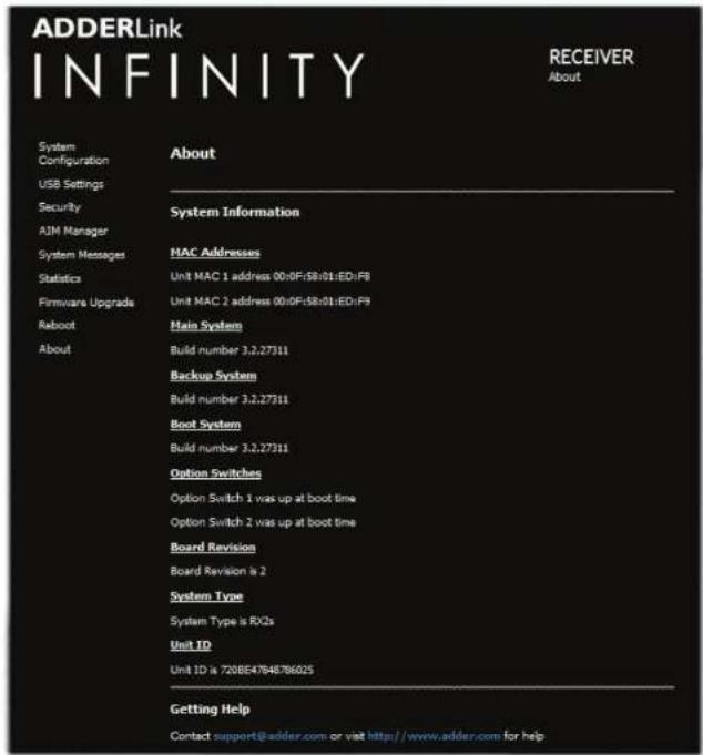
About
This page displays key information about the RX unit that may be requested by Adder Technical Support.
To get here
I Connect your computer to a port on the front panel.
2 Run a web browser and enter the IP address of the Management (ALIF dual only) or System port used: http://192.168.1.42 (management port) or http://169.254.1.32 (system port)
If the address is unknown, perform a manual factory reset.
3 Click the About link.

APPENDIX C - Tips for success when networking ALIF units
ALIF units use multiple strategies to minimize the amount of data that they send across networks. However, data overheads can be quite high, particularly when very high resolution video is being transferred, so it is important to take steps to maximize network efficiency and help minimize data output. The tips given in this section have been proven to produce very beneficial results.
Summary of steps
- Choose the right kind of switch.
• Create an efficient network layout. - Configure the switches and devices correctly.
Choosing the right switch
Layer 2 switches are what bind all of the hosts together in the subnet. However, they are all not created equally, so choose carefully. In particular look for the following:
• Gigabit (1000Mbps) or faster Ethernet ports,
• Support for IGMP v2 (or v3) snooping,
• Support for Jumbo frames up to 9216-byte size,
- High bandwidth connections between switches, preferably Fiber Channel.
- Look for switches that perform their most onerous tasks (e.g. IGMP snooping) using multiple dedicated processors (ASICS).
- Ensure the maximum number of concurrent 'snoopable groups' the switch can handle meets or exceeds the number of ALIF transmitters that will be used to create multicast groups.
- Check the throughput of the switch: Full duplex, 1Gbps up- and down- stream speeds per port.
- Use the same switch make and model throughout a single subnet.
- You also need a Layer 3 switch. Ensure that it can operate efficiently as an IGMP Querier.
For the latest list of switches known to work with ALIF, please download the latest white paper 'Successful AdderLink Infinity Implementation' from www.adder.com/white-papers
Creating an efficient network layout
Network layout is vital. The use of IGMP snooping also introduces certain constraints, so take heed:
- Keep it flat. Use a basic line-cascade structure rather than a pyramid or tree arrangement.
- Keep the distances between the switches as short as possible.
- Ensure sufficient bandwidth between switches to eliminate bottlenecks.
- Where the A.I.M. server is used to administer multiple ALIF transceivers, ensure the A.I.M. server and all ALIF units reside in the same subnet.
- Do not use VGA to DVI converters, instead replace VGA video cards in older systems with suitable DVI replacements. Converters cause ALIF TX units to massively increase data output.
• Wherever possible, create a private network.
The recommended layout
The layout shown below has been found to provide the most efficient network layout for rapid throughput when using IGMP snooping:
![graph TD A["ALIF RX"] --> B["Layer 3 Switch (Quarter)"] C["ALIF RX"] --> B D["ALIF RX"] --> B E["ALIF RX"] --> F["Layer 2 Switch"] G["ALIF RX"] --> F H["ALIF RX"] --> I["Layer 2 Switch"] J["ALIF RX"] --> I K["ALIF TX"] --> B L["ALIF TX"] --> F M["ALIF TX"] --> I N["ALIF TX"] --> I O["ALIF RX"] --> F…](/content/2026/05/810830/images/27ed6e33606c4a9338f12f6aea56f4ddd13c6e14bbc7f7b66351f07e7fdb241b.jpg)
Note: From firmware version 3.1, tree and hierarchical structures of network switches are also supported. The Transmitter now joins its own multicast group so there is always a route from the querier to the transmitter which was previously missing in earlier firmware versions.
• Use no more than two cascade levels.
- Ensure high bandwidth between the two L2 switches and very high bandwidth between the top L2 and the L3. Typically 10GB and 20GB, respectively for 48 port L2 switches.
continued

Configuring the switches and devices
The layout is vital but so too is the configuration:
- Enable IGMP Snooping on all L2 switches.
- Ensure that IGMP Fast-Leave is enabled on all switches with ALIF units connected directly to them.
- Enable the L3 switch as an IGMP Querier.
- Enable Spanning Tree Protocol (STP) on all switches and importantly also enable portfast (only) on all switch ports that have ALIF units connected.
- If any hosts will use any video resolutions using 2048 horizontal pixels (e.g. 2048 x 1152), ensure that Jumbo Frames are enabled on all switches.
- Choose an appropriate forwarding mode on all switches. Use Cut-through if available, otherwise Store and forward.
-
Optimize the settings on the ALIF transmitters:
-
If moving video images are being shown frequently, then leave Frame Skipping at a low percentage and instead reduce the Peak bandwidth limiter.
- Where screens are quite static, try increasing the Background Refresh interval and/or increasing the Frame skipping percentage setting.
Make changes to the ALIF transmitters one at a time, in small steps, and view typical video images so that you can attribute positive or negative results to the appropriate control.
- Ensure that all ALIF units are fully updated to the latest firmware version (at least v2.1).

APPENDIX D - Troubleshooting
Problem: The video image of the ALIF receiver shows horizontal lines across the screen.
This issue is known as Blinding because the resulting video image looks as though you're viewing it through a venetian blind.
When video is transmitted by ALIF units, the various lines of each screen are divided up and transmitted as separate data packets. If the reception of those packets is disturbed, then blinding is caused. The lines are displayed in place of the missing video data packets. There are several possible causes for the loss of data packets:
- Incorrect switch configuration. The problem could be caused by multicast flooding, which causes unnecessary network traffic. This is what IGMP snooping is designed to combat, however, there can be numerous causes of the flooding.
- Speed/memory bandwidth issues within one or more switches. The speed and capabilities of different switch models varies greatly. If a switch cannot maintain pace with the quantity of data being sent through it, then it will inevitably start dropping packets.
- One or more ALIF units may be outputting Jumbo frames due to the video resolution (2048 horizontal pixels) being used. If jumbo frames are output by an ALIF unit, but the network switches have not been configured to use jumbo frames, the switches will attempt to break the large packets down into standard packets. This process introduces a certain latency and could be a cause for dropped packets.
- One or more ALIF units may be using an old firmware version. Firmware versions prior to v2.1 exhibited an issue with the timing of IGMP join and leave commands that caused multicast flooding in certain configurations.
Remedies:
- Ensure that IGMP snooping is enabled on all switches within the subnet.
- Where each ALIF unit is connected as the sole device on a port connection to a switch, enable IGMP Fast-Leave (aka Immediate Leave) to reduce unnecessary processing on each switch.
- Check the video resolution(s) being fed into the ALIF transmitters. If resolutions using 2048 horizontal pixels are unavoidable then ensure that Jumbo frames are enabled on all switches.
- Check the forwarding mode on the switches. If Store and forward is being used, try selecting Cut-through as this mode causes reduced latency on lesser switch designs.
- Ensure that one device within the subnet is correctly configured as an IGMP Querier, usually a layer 3 switch or multicast router.
- Ensure that the firmware in every ALIF unit is version 2.1 or greater.
- Try adjusting the transmitter settings on each ALIF to make the output data stream as efficient as possible. See ALIF transmitter video settings for details.
continued

Problem: The mouse pointer of the ALIF receiver is slow or sluggish when moved across the screen.
This issue is often related to either using dithering on the video output of one or more transmitting computers or using VGA-to-DVI video converters.
Dithering is used to improve the perceived quality and color depth of images by diffusing or altering the color of pixels between video frames. This practice is commonly used on Apple Mac computers using ATI or Nvidia graphics cards. VGA-to-DVI converters unwittingly produce a similar issue by creating high levels of pixel background noise.
ALIF units attempt to considerably reduce network traffic by transmitting only the pixels that change between successive video frames. When dithering is enabled and/or VGA-to-DVI converters are used, this can have the effect of changing almost every pixel between each frame, thus forcing the ALIF transmitter to send the whole of every frame: resulting in greatly increased network traffic and what's perceived as sluggish performance.
Remedies:
- Linux PCs
Check the video settings on the PC. If the Dither video box option is enabled, disable it.
• Apple Mac with Nvidia graphics
Use the Adder utility for Mac's – Contact technical support.
• Apple Mac with ATI graphics
Enable the Magic Eye dither removal feature.
- Windows PCs
If you suspect these issues with PC's, contact technical support for assistance. - Replace old VGA adapters on host computers with DVI video cards.
Problem: My monitor is displaying a pink screen
It is possible that the source computer and ALIF transmitter are sending a high resolution Dual Link signal in response to a request from your Dual Link monitor. However, your ALIF receiver is unable to correctly process the signal, causing the pink screen issue (DVI resolutions above 1920 x 1200 are generally Dual Link).
ALIF2002T and 2112T transmitters are able to send Dual Link video when requested, however, an ALIF2000R receiver is required to process the higher resolution signal fully at the other end. Other receivers, such as the ALIF1000R, 1002R and 2020R units cannot process Dual Link DVI as they are Single Link devices.
Ensure that the ALIF transmitter is set to supply a Single Link EDID to the graphics card. When the video source is changed to a Single Link video resolution, the pink screen should disappear and the video should be displayed normally. Alternatively, change the monitor to a Single Link DVI monitor.
It is important not to mix Dual Link Transmitters with Single Link Receivers.
On an A.I.M. controlled system, ensure that the Video compatibility check is enabled as this ensures that the correct video mode is displayed for the monitor being used.
Problem: The audio output of the ALIF receiver sounds like a scratched record.
This issue is called Audio crackle and is a symptom of the same problem that produces blinding (see previous page). The issue is related to missing data packets.
Remedies:
As per blinding discussed previously.
Problem: A.I.M. cannot locate working ALIF units.
There are a few possible causes:
- The ALIF units must be reset back to their zero config IP addresses for A.I.M. discovery. If you have a working network of ALIF's without A.I.M. and then add A.I.M. to the network A.I.M. will not discover the ALIFs until they are reset to the zero config IP addresses.
- This could be caused by Layer 2 Cisco switches that have Spanning Tree Protocol (STP) enabled but do not also have portfast enabled on the ports to which ALIF units are connected. Without portfast enabled, ALIF units will all be assigned the same zero config IP address at reboot and A.I.M. will only acquire them one at a time on a random basis.
You can easily tell whether portfast is enabled on a switch that is running STP: When you plug the link cable from a working ALIF unit into the switch port, check how long it takes for the port indicator to change from orange to green. If it takes roughly one second, portfast is on; if it takes roughly thirty seconds then portfast is disabled.
Remedies:
- Ensure that the ALIF units and the A.I.M. server are located within the same subnet because A.I.M. cannot cross subnet boundaries.
- Manually reset the ALIF units to their zero config IP addresses.
- Enable portfast on all switch ports that have ALIF units attached to them or try temporarily disabling STP on the switches while A.I.M. is attempting to locate ALIF units.

APPENDIX E - Glossary
Internet Group Management Protocol
Where an ALIF transmitter is required to stream video to two or more receivers, multicasting is the method used.
Multicasting involves the delivery of identical data to multiple receivers simultaneously without the need to maintain individual links. When multicast data packets enter a subnet, the natural reaction of the switches that bind all the hosts together within the subnet, is to spread the multicast data to all of their ports. This is referred to as Multicast flooding and means that the hosts (or at least their network interfaces) are required to process plenty of data that they didn't request. IGMP offers a partial solution.
The Internet Group Management Protocol (IGMP) is designed to prevent multicast flooding by allowing Layer 3 switches to check whether host computers within their care are interested in receiving particular multicast transmissions. They can then direct multicast data only to those points that require it and can shut off a multicast stream if the subnet has no recipients.
There are currently three IGMP versions: 1, 2 and 3, with each version building upon the capabilities of the previous one:
- IGMPvI allows host computers to opt into a multicast transmission using a Join Group message, it is then incumbent on the router to discover when they no longer wish to receive; this is achieved by polling them (see IGMP Querier below) until they no longer respond.
- IGMPv2 includes the means for hosts to opt out as well as in, using a Leave Group message.
- IGMPv3 encompasses the abilities of versions 1 and 2 but also adds the ability for hosts to specify particular sources of multicast data.
AdderLink Infinity units make use of IGMPv2 when performing multicasts to ensure that no unnecessary congestion is caused.
IGMP Snooping
The IGMP messages are effective but only operate at layer 2 - intended for routers to determine whether multicast data should enter a subnet. A relatively recent development has taken place within the switches that glue together all of the hosts within each subnet: IGMP Snooping. IGMP snooping means these layer 2 devices now have the ability to take a peek at the IGMP messages. As a result, the switches can then determine exactly which of their own hosts have requested to receive a multicast – and only pass on multicast data to those hosts.
IGMP Querier
When IGMP is used, each subnet requires one Layer 3 switch to act as a Querier. In this lead role, the switch periodically sends out IGMP Query messages and in response all hosts report which multicast streams they wish to receive. The Querier device and all snooping Layer 2 switches, then update their lists accordingly (the lists are also updated when Join Group and Leave Group (IGMPv2) messages are received).
IGMP Fast-Leave (aka Immediate Leave)
When a device/host no longer wishes to receive a multicast transmission, it can issue an IGMP Leave Group message as mentioned above. This causes the switch to issue an IGMP Group-Specific Query message on the port (that the Leave Group was received on) to check no other receivers exist on that connection that wish to remain a part of the multicast. This process has a cost in terms of switch processor activity and time.
Where ALIF units are connected directly to the switch (with no other devices on the same port) then enabling IGMP Fast-Leave mode means that switches can immediately remove receivers without going through a full checking procedure. Where multiple units are regularly joining and leaving multicasts, this can speed up performance considerably.
Jumbo frames (Jumbo packets)
Since its commercial introduction in 1980, the Ethernet standard has been successfully extended and adapted to keep pace with the ever improving capabilities of computer systems. The achievable data rates, for instance, have risen in ten-fold leaps from the original 10Mbit/s to a current maximum of 100Gbit/s.
While data speeds have increased massively, the standard defining the number of bytes (known as the Payload) placed into each data packet has remained resolutely stuck at its original level of 1500 bytes. This standard was set during the original speed era (10Mbits/s) and offered the best compromise at that speed between the time taken to process each packet and the time required to resend faulty packets due to transmission errors.
But now networks are much faster and files/data streams are much larger; so time for a change? Unfortunately, a wholesale change to the packet size is not straightforward as it is a fundamental standard and changing it would mean a loss of backward compatibility with older systems.
Larger payload options have been around for a while, however, they have often been vendor specific and at present they remain outside the official standard. There is, however, increased consensus on an optional 'Jumbo' payload size of 9000 bytes and this is fully supported by the AdderLink Infinity (ALIF) units.
Jumbo frames (or Jumbo packets) offer advantages for ALIF units when transmitting certain high resolution video signals across a network. This is because the increased data in each packet reduces the number of packets that need to be transferred and dealt with - thus reducing latency times. The main problem is that for jumbo frames to be possible on a network, all of the devices on the network must support them.
Spanning Tree Protocol (STP)
In order to build a robust network, it is necessary to include certain levels of redundancy within the interconnections between switches. This will help to ensure that a failure of one link does not lead to a complete failure of the whole network.
The danger of multiple links is that data packets, especially multicast packets, become involved in continual loops as neighbouring switches use the duplicated links to send and resend them to each other.
To prevent such bridging loops from occurring, the Spanning Tree Protocol (STP), operating at layer 2, is used within each switch. STP encourages all switches to communicate and learn about each other. It prevents bridging loops by blocking newly discovered links until it can discover the nature of the link: is it a new host or a new switch?
The problem with this is that the discovery process can take up to 50 seconds before the block is lifted, causing problematic timeouts.
The answer to this issue is to enable the portfast variable for all host links on a switch. This will cause any new connection to go immediately into forwarding mode. However, take particular care not to enable portfast on any switch to switch connections as this will result in bridging loops.
Forwarding modes
In essence, the job of a layer 2 switch is to transfer as fast as possible, data packets arriving at one port out to another port as determined by the destination address. This is known as data forwarding and most switches offer a choice of methods to achieve this. Choosing the most appropriate forwarding method can often have a sizeable impact on the overall speed of switching:
- Store and forward is the original method and requires the switch to save each entire data packet to buffer memory, run an error check and then forward if no error is found (or otherwise discard it).
- Cut-through was developed to address the latency issues suffered by some store and forward switches. The switch begins interpreting each data packet as it arrives. Once the initial addressing information has been read, the switch immediately begins forwarding the data packet while the remainder is still arriving. Once all of the packet has been received, an error check is performed and, if necessary, the packet is tagged as being in error. This checking 'on-the-fly' means that cut-through switches cannot discard faulty packets themselves. However, on receipt of the marked packet, a host will carry out the discard process.
- Fragment-free is a hybrid of the above two methods. It waits until the first 64 bits have been received before beginning to forward each data packet. This way the switch is more likely to locate and discard faulty packets that are fragmented due to collisions with other data packets.
- Adaptive switches automatically choose between the above methods. Usually they start out as a cut-through switches and change to store and forward or fragment-free methods if large number of errors or collisions are detected.
So which one to choose? The Cut-through method has the least latency so is usually the best to use with AdderLink Infinity units. However, if the network components and/or cabling generate a lot of errors, the Store and forward method should probably be used. On higher end store and forward switches, latency is rarely an issue.
Layer 2 and Layer 3: The OSI model
When discussing network switches, the terms Layer 2 and Layer 3 are very often used. These refer to parts of the Open System Interconnection (OSI) model, a standardized way to categorize the necessary functions of any standard network.
There are seven layers in the OSI model and these define the steps needed to get the data created by you (imagine that you are Layer 8) reliably down onto the transmission medium (the cable, optical fiber, radio wave, etc.) that carries the data to another user; to complete the picture, consider the transmission medium is Layer 0. In general, think of the functions carried out by the layers at the top as being complex, becoming less complex as you go lower down.
![graph TD A["Layer 1"] --> B["Layer 2"] B --> C["Layer 3"] C --> D["Layer 4"] D --> E["Layer 5"] E --> F["Layer 6"] F --> G["Layer 7"] H["Physical"] --> B I["Data Link"] --> C J["Network"] --> D K["Transport"] --> E L["Session"] --> F M["Application"] --> G](/content/2026/05/810830/images/8aeb14b84ae6f1a5e35453b61e5db2bf8a4eaba130c27e02c38618a1dfc32812.jpg)
Network connection
As your data travel down from you towards the transmission medium (the cable), they are successively encapsulated at each layer within a new wrapper (along with a few instructions), ready for transport. Once transmission has been made to the intended destination, the reverse occurs: Each wrapper is stripped away and the instructions examined until finally only the original data are left.
So why are Layer 2 and Layer 3 of particular importance when discussing AdderLink Infinity? Because the successful transmission of data relies upon fast and reliable passage through network switches – and most of these operate at either Layer 2 or Layer 3.
The job of any network switch is to receive each incoming network packet, strip away only the first few wrappers to discover the intended destination then rewrap the packet and send it in the correct direction.
continued

In simplified terms, the wrapper that is added at Layer 2 (by the sending system) includes the physical address of the intended recipient system, i.e. the unique MAC address (for example, 09:f8:33:d7:66:12) that is assigned to every networking device at manufacture. Deciphering recipients at this level is more straightforward than at Layer 3, where the address of the recipient is represented by a logical IP address (e.g. 192.168.0.10) and requires greater knowledge of the surrounding network structure. Due to their more complex circuitry, Layer 3 switches are more expensive than Layer 2 switches of a similar build quality and are used more sparingly within installations.

APPENDIX F - Cable pinouts, video modes and general specifications
RS232 'null-modem' cable pin-out
![graph LR RXD["2"] --> RXD2["2"] TXD["3"] --> TXD2["3"] DTR["4"] --> DTR2["4"] DSR["6"] --> DSR2["6"] DCD["1"] --> DCD2["1"] GND["5"] --> GND2["5"] RTS["7"] --> RTS2["7"] CTS["8"] --> CTS2["8"] RXD2 --> RXD TXD2 --> TXD DTR2 --> DTR DSR2 --> DSR DCD2 --> DCD GND2 --> GND RTS2 --> RTS CTS2 --> CTS](/content/2026/05/810830/images/011b80b8aac1b8bd07409c36717fea5b9c4d805474da0e1a120b3296ec6106b3.jpg)
Supported video modes
ALIF units support all VESA and CEA video modes.
General specifications
Casing (w x h x d): 198mm (7.92") × 44mm (1.76") × 150mm (6.0")
Construction: IU compact case, robust metal design
Weight: 1.1kg (2.4lbs)
Mount kits: Rack mount - single or dual units per IU slot.
VESA monitor / wall mount chassis.
Power to adapter: 100-240VAC 50/60Hz, 0.8A,
Power to unit: 5VDC 20W
Operating temp: 0°C to 40°C (32°F to 104°F)
Approvals: CE, FCC
APPENDIX G - Fiber modules and cables
To suit your installation layout, two fiber modules are available for the ALIF dual units to suit various fiber optic cables. The specifications for all are summarized in the table below:
| Fiber Type | Fiber size | Fiber Type | Coding | Distance at 1Gbps | Adder part number for SFP module | Bar color | Conn. type | ||
| Normal Applications | Military Applications | Suggested Print Nomenclature | |||||||
| OM1 (62.5/125) | Multimode | (TIA-492AAAA) | Orange | Slate | 62.5/125 | 220m | SFP-MM-LC | Black | LC |
| OM2 (50/125) | Multimode | (TIA-492AAAB) | Orange | Orange | 50/125 | 550m | “ | “ | “ |
| OM3 (50/125) | Multimode | (850 nm Laser-optimized)(TIA-492AAAC) | Aqua | Undefined | 850 LO 50 /125 | 550m | “ | “ | “ |
| OM4 (50/125) | Multimode | (850 nm Laser-optimized)(TIA-492AAAC) | Aqua | Undefined | 850 LO 50 /125 | 550m | “ | “ | “ |
| OS1 and OS2 | (9/125) | Single-mode(TIA-492C000 / TIA-492E000) | Yellow | Yellow | SM/NZDS, SM | 10Km | SFP-SM-LC | Blue | LC |

APPENDIX H - Mounting options
There are several mounting methods for transmitter and receiver units:
• The supplied four self-adhesive rubber feet
• Optional single unit rack brackets - this page
- Optional dual unit rack brackets
• Optional VESA bracket mount
Single unit rack brackets
The optional single unit brackets (plus four screws), allow a unit to be secured within a standard rack half width slot.
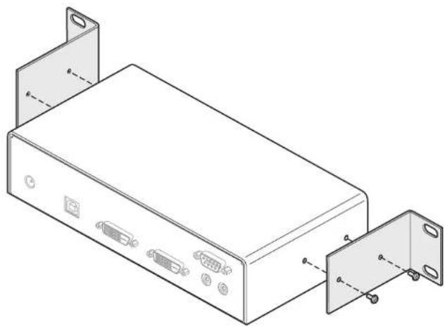
IMPORTANT - allow space for airflow
The ALIF units and their power supplies generate heat when in operation and will become warm to the touch.
Do not place them in locations where air cannot circulate to cool the equipment. When mounting units within a rack chassis, allow a 1/3rd U space (1.5cm) between rows of devices:
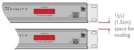
Do not operate the equipment in ambient temperatures exceeding 40° C. Do not place the products in contact with equipment whose surface temperature exceeds 40° C.

Double unit rack brackets
This optional kit comprises four brackets (plus twelve screws) and allows two ALIF units to be mounted side by side and fitted into a IU rack slot.
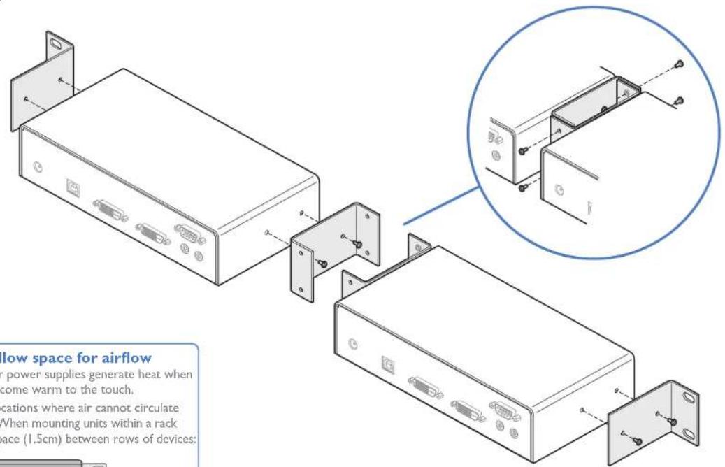
IMPORTANT - allow space for airflow
The ALIF units and their power supplies generate heat when in operation and will become warm to the touch.
Do not place them in locations where air cannot circulate to cool the equipment. When mounting units within a rack chassis, allow a 1/3rd U space (1.5cm) between rows of devices:
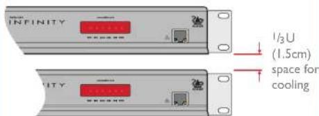
Do not operate the equipment in ambient temperatures exceeding 40°C. Do not place the products in contact with equipment whose surface temperature exceeds 40°C.

VESA bracket mount
This optional kit comprises a bracket that allows a single AdderLink Infinity module to be mounted onto the rear of a video display*. The kit includes the bracket plus eight screws.
* The video display must adhere to the VESA standard for mounting holes on its rear panel.
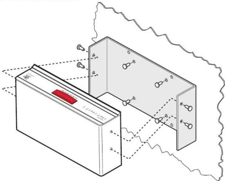

SAFETY INFORMATION
• For use in dry, oil free indoor environments only.
- Warning - live parts contained within power adapter.
- No user serviceable parts within power adapter - do not dismantle.
- Plug the power adapter into a socket outlet close to the module that it is powering.
- Replace the power adapter with a manufacturer approved type only.
- Do not use the power adapter if the power adapter case becomes damaged, cracked or broken or if you suspect that it is not operating properly.
- If you use a power extension cord with the units, make sure the total ampere rating of the devices plugged into the extension cord does not exceed the cord's ampere rating. Also, make sure that the total ampere rating of all the devices plugged into the wall outlet does not exceed the wall outlet's ampere rating.
- Do not attempt to service the units yourself.
WARRANTY
Adder Technology Ltd warrants that this product shall be free from defects in workmanship and materials for a period of two years from the date of original purchase. If the product should fail to operate correctly in normal use during the warranty period, Adder will replace or repair it free of charge. No liability can be accepted for damage due to misuse or circumstances outside Adder's control. Also Adder will not be responsible for any loss, damage or injury arising directly or indirectly from the use of this product. Adder's total liability under the terms of this warranty shall in all circumstances be limited to the replacement value of this product.
If any difficulty is experienced in the installation or use of this product that you are unable to resolve, please contact your supplier.
RADIO FREQUENCY ENERGY
A Category 5 (or better) twisted pair cable must be used to connect the units in order to maintain compliance with radio frequency energy emission regulations and ensure a suitably high level of immunity to electromagnetic disturbances.
All other interface cables used with this equipment must be shielded in order to maintain compliance with radio frequency energy emission regulations and ensure a suitably high level of immunity to electromagnetic disturbances.
European EMC directive 2004/108/EC
This equipment has been tested and found to comply with the limits for a class A computing device in accordance with the specifications in the European standard EN55022. These limits are designed to provide reasonable protection against harmful interference. This equipment generates, uses and can radiate radio frequency energy and if not installed and used in accordance with the instructions may cause harmful interference to radio or television reception. However, there is no guarantee that harmful interference will not occur in a particular installation. If this equipment does cause interference to radio or television reception, which can be determined by turning the equipment on and off, the user is encouraged to correct the interference with one or more of the following measures: (a) Reorient or relocate the receiving antenna. (b) Increase the separation between the equipment and the receiver. (c) Connect the equipment to an outlet on a circuit different from that to which the receiver is connected. (d) Consult the supplier or an experienced radio/TV technician for help.
FCC Compliance Statement (United States)
This equipment generates, uses and can radiate radio frequency energy and if not installed and used properly, that is, in strict accordance with the manufacturer's instructions, may cause interference to radio communication. It has been tested and found to comply with the limits for a class A computing device in accordance with the specifications in Subpart J of part 15 of FCC rules, which are designed to provide reasonable protection against such interference when the equipment is operated in a commercial environment. Operation of this equipment in a residential area may cause interference, in which case the user at his own expense will be required to take whatever measures may be necessary to correct the interference. Changes or modifications not expressly approved by the manufacturer could void the user's authority to operate the equipment.
Canadian Department of Communications RFI statement
This equipment does not exceed the class A limits for radio noise emissions from digital apparatus set out in the radio interference regulations of the Canadian Department of Communications.
Contact: www.adder.com/contact-details
Support: forum.adder.com
Documentation by:

www.ctxd.com
© 2015 Adder Technology Limited
All trademarks are acknowledged.
Part No. MAN-ALIF2000-ADDER • Release 3.4

Index
A
Active Copper 14
Adaptive 45
AFZ 3.26
Anti-dither support 3
B
Bracket
rack mount 48,49
Browser-based utility 20
C
Cable
null-modem 46
Cloning displays 33
CODEC 3
Compression 26
Configuration
browser-based utility 20 switches 21
Connections
network link 14
overview 10
RX audio 17
RX AUX port 18
RX power in 18
RX USB devices 17
RX video display 16
TX audio links 12
TX AUX port 13
TX power in 13
TX USB link 12
TX video link II
Connectors
overview 5,6
Cut-through 45
D
Dimensions 46
Display cloning 33
Dithering 3
F
Factory reset 19
Fast-Leave 43
Fibre Channel 14
Firmware
upgrade 21
Forwarding modes 45
Fragment-free 45
Frame Skipping 26
Front panel 5,6
Front panel indicators 22
G
Gigabit Ethernet 14
1
IGMP 43
fast-leave 43
querier 43
snooping 43
Indicators 5,6,22
Initial configuration 19
1
Jumbo frames (packets) 43
L
Layers 2 and 3 45
Link cable lengths 14
M
Magic Eye 3,26
Management port 6,25,32
RX settings 32
TX settings 25
Multicast settings 33
N
Network layout 39
Network switch
choosing 39
Null-modem cable
pin-out 46
0
Optimization
statistics for 29,37
Options switches 21
OSI model 45
Q
Querier 43
R
Rack mounting 48
Rear panel 5,6
Reset
manual 19
s
Safety information 51
SFP module 14
Snooping 43
Spanning Tree Protocol 44
Specifications 46
Statistics
graphing 29,37
Store and forward 45
Switch
choosing 39
configuring 40
System port 5,6,14,25,32
RX settings 32
TX settings 25
T
Teaming port 5,6,14,25,32
RX settings 32
TX settings 25
TLS 3
Transport Layer Security 3
Troubleshooting 41
U
Upgrade
firmware 21
V
Video modes 46
W
Warranty 51
Weight 46


- CONTENTS
- INTRODUCTION
- INSTALLATION
- CONFIGURATION
- OPERATION
- FURTHER INFORMATION
- INDEX
- WELCOME
- MIXING ALIF DUAL UNITS WITH THE ORIGINAL ALIF 1000 SERIES
- ONE-TO-ONE CONFIGURATION
- ONE-TO-MANY CONFIGURATION
- ALIF AND A.I.M
- ALIF FEATURES
- AFZ LOSSLESS CODEC
- NEW FEATURE: AFZ+ CODEC
- MAGIC EYE (ANTI-DITHER SUPPORT ADDED)
- TRANSPORT LAYER SECURITY (TLS)
- TEAMING OPERATION
- FIRMWARE VERSION 3.3 (OR GREATER)
- IMPORTANT UPGRADE NOTES
- ADDERLINK INFINITY (1002) UNIT FEATURES
- ADDERLINK INFINITY DUAL UNIT FEATURES
- OPTIONAL EXTRAS
- CONNECTIONS
- MOUNTING
- TX VIDEO LINK
- TO MAKE A VIDEO LINK
- TX AUDIO LINKS
- TO MAKE AUDIO LINKS
- TX USB LINK
- TO MAKE A USB LINK
- TX AUX (SERIAL) PORT
- TO CONNECT THE AUX PORT
- TX POWER IN
- TO APPLY POWER IN
- TX/RX HIGH SPEED LINKS
- TO LINK ALIF DUAL UNITS USING THE TEAMING PORT
- TO LINK ALIF UNITS USING THE SYSTEM PORT
- CABLE AND FIBER DETAILS
- TX/RX MANAGEMENT PORT (ALIF DUAL UNITS ONLY)
- TO CONNECT A COMPUTER TO ACCESS THE CONFIGURATION UTILITY
- RX VIDEO DISPLAY
- TO CONNECT VIDEO DISPLAYS
- RX MICROPHONE & SPEAKERS
- TO CONNECT A MICROPHONE (OR LINE IN) AND/OR SPEAKERS
- RX USB DEVICES
- TO CONNECT A USB DEVICE
- SUPPORTED USB DEVICES
- RX AUX (SERIAL) PORT
- RX POWER IN
- DIRECT LINKING
- NETWORKED LINKING
- MANUAL FACTORY RESET
- TO PERFORM A MANUAL FACTORY RESET
- ADDERLINK INFINITY BROWSER-BASED CONFIGURATION UTILITY
- TO ACCESS THE BROWSER-BASED CONFIGURATION UTILITY
- PERFORMING AN UPGRADE
- FINDING THE LATEST UPGRADE FILES
- OPTIONS SWITCHES
- SWITCH I - FIRMWARE IMAGE SELECT
- FRONT PANEL INDICATORS
- INDICATORS
- GETTING ASSISTANCE
- APPENDIX A - TRANSMITTER (TX) UNIT CONFIGURATION PAGES
- UNIT NAME
- UNIT DESCRIPTION
- SYSTEM PORT
- MANAGEMENT PORT (ALIF DUAL MODELS ONLY - NOT SHOWN IN SCREENSHOT LEFT)
- TEAMING PORT
- ENABLE OPTIONS
- SERIAL PORT OPTIONS
- IDENTIFY UNIT
- THUMBNAIL
- TARGET MULTICAST CONFIGURATION
- PEAK BANDWIDTH LIMITER PERCENTAGE
- BACKGROUND REFRESH
- ENABLE MAGIC EYE
- USE DEFAULT DDC AND CHOOSE DEFAULT DDC
- ENABLE HOT PLUG DETECT
- PERIOD OF HOT PLUG DETECT SIGNAL
- FRAME SKIPPING PERCENTAGE
- COMPRESSION
- TO GET HERE
- ENABLE DUMMY BOOT KEYBOARD
- DISABLE HI-SPEED
- HUB SIZE
- RESERVED PORT RANGE
- USB ENCRYPTION
- CONTROL ENCRYPTION
- SECURE WEB PAGES WITH PASSWORD
- CHANGE/CONFIRM PASSWORD
- ENABLE AIM CONTROL
- ENABLE SYSTEM MESSAGES
- SEND SYSTEM MESSAGES TO REMOTE LOG SERVER
- STORE SYSTEM MESSAGES IN UNIT
- UPDATE NOW
- ENABLE COLLECTION OF BANDWIDTH STATISTICS
- SUBMIT
- UPGRADE
- REBOOT
- TX ABOUT
- ABOUT
- APPENDIX B - RECEIVER (RX) UNIT CONFIGURATION PAGES
- RX SYSTEM CONFIGURATION (1 OF 2)
- ADDERLINK
- INFINITY
- RECEIVER
- AUDIO INPUT TYPE
- ENABLE VIDEO COMPATIBILITY CHECK (FOR DVI-D I AND 2 ON ALIF DUAL MODELS)
- FORCE VIDEO REFRESH RATE TO 60HZ
- VIDEO SWITCHING
- TARGET TRANSMITTER UNIT SETTINGS
- ALLOW HUMAN INTERFACE DEVICES (HID) ONLY
- ISOCHRONOUS ENDPOINT OSD ALERTS
- ENABLE ISOCHRONOUS ENDPOINT ATTACH
- PORT RESERVATION
- ADVANCED FEATURES
- ENCRYPTION
- RX ABOUT
- APPENDIX C - TIPS FOR SUCCESS WHEN NETWORKING ALIF UNITS
- SUMMARY OF STEPS
- CHOOSING THE RIGHT SWITCH
- CREATING AN EFFICIENT NETWORK LAYOUT
- THE RECOMMENDED LAYOUT
- CONFIGURING THE SWITCHES AND DEVICES
- APPENDIX D - TROUBLESHOOTING
- REMEDIES
- PROBLEM: THE MOUSE POINTER OF THE ALIF RECEIVER IS SLOW OR SLUGGISH WHEN MOVED ACROSS THE SCREEN
- PROBLEM: MY MONITOR IS DISPLAYING A PINK SCREEN
- PROBLEM: THE AUDIO OUTPUT OF THE ALIF RECEIVER SOUNDS LIKE A SCRATCHED RECORD
- PROBLEM: A.I.M. CANNOT LOCATE WORKING ALIF UNITS
- APPENDIX E - GLOSSARY
- INTERNET GROUP MANAGEMENT PROTOCOL
- IGMP SNOOPING
- IGMP QUERIER
- IGMP FAST-LEAVE (AKA IMMEDIATE LEAVE)
- JUMBO FRAMES (JUMBO PACKETS)
- SPANNING TREE PROTOCOL (STP)
- FORWARDING MODES
- LAYER 2 AND LAYER 3: THE OSI MODEL
- APPENDIX F - CABLE PINOUTS, VIDEO MODES AND GENERAL SPECIFICATIONS
- SUPPORTED VIDEO MODES
- GENERAL SPECIFICATIONS
- APPENDIX G - FIBER MODULES AND CABLES
- APPENDIX H - MOUNTING OPTIONS
- SINGLE UNIT RACK BRACKETS
- IMPORTANT - ALLOW SPACE FOR AIRFLOW
- DOUBLE UNIT RACK BRACKETS
- VESA BRACKET MOUNT
- SAFETY INFORMATION
- WARRANTY
- RADIO FREQUENCY ENERGY
- EUROPEAN EMC DIRECTIVE 2004/108/EC
- FCC COMPLIANCE STATEMENT (UNITED STATES)
- CANADIAN DEPARTMENT OF COMMUNICATIONS RFI STATEMENT
- A
- B
- C
- D
- F
- G
- 1
- L
- M
- N
- 0
- Q
- R
- S
- T
- U
- V
- W
Brand : Adder
Model : ALIF2020R
Category : Audio/video extender