
Femto Mega I - 3D Printer Orbbec - Free user manual and instructions
Find the device manual for free Femto Mega I Orbbec in PDF.


| Product Type | Industrial 3D Depth and RGB Camera |
| Dimensions (W x H x D) | 180 mm × 50 mm × 110 mm |
| Weight | 1080 g |
| Power Supply | PoE+ (IEEE 802.3at, 24W) or DC 12-24V |
| Power Consumption | Average 11W, Peak 18W |
| Depth Technology | iToF (Indirect Time-of-Flight) |
| Depth Resolution (Max) | 1024 × 1024 (WFOV) / 640 × 576 (NFOV) |
| RGB Resolution (Max) | 3840 × 2160 (4K) |
| Depth Range | 0.25 m – 5.46 m (depending on mode) |
| Field of View (Depth WFOV) | 120° × 120° |
| Field of View (Depth NFOV) | 75° × 65° |
| RGB Field of View | 80° × 51° |
| Processor | NVIDIA Jetson Nano™ |
| Data Interface | Gigabit Ethernet (M12 X-coding) |
| Connectors | 8-pin M12 Ethernet, 12-pin M12 for power/I/O/RS232 |
| Ingress Protection | IP65 |
| Operating Temperature | 0°C to 45°C |
| Storage Temperature | -20°C to 60°C |
| Certifications | CE, FCC, RoHS, REACH, Class 1 (Laser), WEEE |
| SDK Compatibility | Windows and Linux (Orbbec SDK) |
| Multi-Camera Sync | Supported via 12-pin connector |
| Cleaning Instructions | Use soft, lint-free cloth; lens cleaner for lens; avoid alcohol or solvents |
| Safety Precautions | Class 1 laser; do not look into laser for >20s; keep away from children; avoid dropping |
| Spare Parts / Repairability | Disassembly voids warranty; contact manufacturer for repairs |
Frequently Asked Questions - Femto Mega I Orbbec
User questions about Femto Mega I Orbbec
0 question about this device. Answer the ones you know or ask your own.
Ask a new question about this device
Download the instructions for your 3D Printer in PDF format for free! Find your manual Femto Mega I - Orbbec and take your electronic device back in hand. On this page are published all the documents necessary for the use of your device. Femto Mega I by Orbbec.
USER MANUAL Femto Mega I Orbbec
| Product Brief | 02 |
| Product Specifications | 03 |
| Product Information | 04 |
| SDK | 05 |
| Camera Setup and Operation | 05 |
| Installation Guide | 07 |
| Product Drawings | 08 |
| Field of View Illustration | 08 |
| Multi-Camera Synchronization | 09 |
| Safety and Handling | 09 |
| Glossary of Terms | 10 |
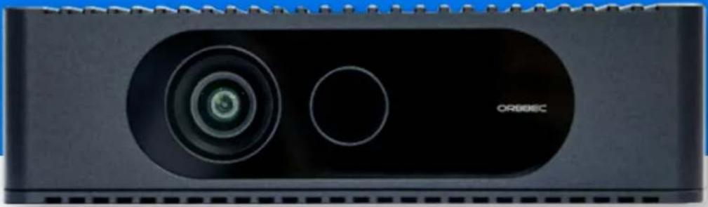
natural_image
Close-up of a black rectangular electronic device with a circular lens and circular button, labeled 'ORIGEC' (no additional text or symbols visible)Developed with

Microsoft

NVIDIA
1. Product Brief
Product Overview
Femto Mega I is a programmable multi-mode industrial grade (IP65) Depth and RGB camera with real-time streaming of processed images over Ethernet connections. The camera uses Microsoft's industry proven TOF technology and the NVIDIA ^ Jetson ^TM platform to deliver a software-defined Depth and RGB vision platform for computer vision and AI developers.
Product Features
- 1Mega Pixel ToF sensor
- 4K RGB
- Processor: NVIDIA Jetson Nano™
• Data interfaces: Ethernet - Power: PoE/DC
- Trigger/Sync Control
- OS: Windows or Linux
- Operating temperature: 0^ C 45^ C
Product Characteristics
Performance
• High resolution sensor provides detailed scene understanding
- Wide Field of View covers a large area
- Various operating modes for different applications
• IP65 dust and water protection
Programmability
- In-camera processing of advanced depth vision algorithms
- Integrated NVIDIA Jetson Nano™ system-on-module for AI processing can remove need for dedicated compute
- Orbbec SDK enables easy setup and provides a rich set of APIs for integration with various applications
Packaging
- Depth and RGB cameras in a single device
- Combined data and power with Power over Ethernet (PoE) connections eliminate need for multiple cables
- Can be directly connected to servers or cloud as an IoT device
2. Product Specifications
| Parameter Specifications | |
| Model OI-BC3001 | |
| VID/PID 0x2BC5/0x06c0 | |
| Technology iToF | |
| Shutter Type IR: Global | Shutter; Color: Rolling Shutter |
| Wavelength 850nm | |
| Mode | Resolution FoV FPS Range Format | ||||
| Depth(Snapshot Mode) | 1024 x 1024 | H 120°V 120° | 3, 10 | 0.25m – 2.21m | Y16 |
| 640 x 576 | H 75°V 65° | 3, 10 | 0.5m – 3.86m | ||
| Depth(Stream Mode) | 1024 x 1024 | H 120°V 120° | 5, 15 0.25m – | 2.21m | |
| 512 x 512 | 5, 15, 25, 30 | 0.25m – 2.88m | |||
| 640 x 576 | H 75°V 65° | 5, 15, 25, 30 | 0.5m – 3.86m | ||
| 320 x 288 | 5, 15, 25, 30 | 0.5m – 5.46m | |||
| RGB(Snapshot Mode) | 3840 x 2160 | H 80°V 51° | 3 | N/A | YUYV |
| 1920 x 1080 | 3, 10 | N/A | |||
| RGB(Stream Mode) | 3840 x 2160 | 5, 15, 25 | N/A | YUY2,MJPG,H.264,H.265 | |
| 2560 x 1440 | 5, 15, 25, 30 | N/A | |||
| 1920 x 1080 | 5, 15, 25, 30 | N/A | |||
| 1280 x 720 | 5, 15, 25, 30 | N/A | |||
| Depth typical systematic error (accuracy)* < 11 mm + 0.1% distanceDepth random error std. dev (precision)A ≤ 17 mm,Passive-IR mode supported*15% to 95% reflectivity at 850nm, 2.2 μW/cm2/nm without multi-path interference.Depending on object reflectivity, depth may be provided outside of the operating range indicated above.Supported SDK: Snapshot Mode – Orbbec Industry SDK; Stream Mode – Orbbec SDKSwitching to Stream Mode requires editing of the Sync Config in Orbbec SDK and a reboot of the device. To revert to Snapshot Mode, a factory reset in the Orbbec SDK is necessary. | |||||
| Parameter | Specifications |
| IMU | 6 DoF; Frequency range: 50-2,000Hz; Data format: float |
| Mirror Mode | Supported, non-mirror by default |
| Processing | NVIDIA Jetson NanoTM for in-camera processing |
| Data Connection | M12 A-coding Connector 12 pinsM12 X-coding Connector 8 pins |
| Power Mode | DC/POE |
| Power Input | DC 12~24VPOE+/802.3at (24W) |
| Operating Modes | POE Power + Gigabit Ethernet DataDC Power + Gigabit Ethernet Data |
| Power Consumption | Average: 11 W, Peak: 18W |
| Operating Environment | 0°C - 45°C, 8%RH - 90 %RH (non-condensing), Indoor/Semi-Outdoor |
| Supported Functions | D2C, Multi-Camera Sync |
| Dimensions (W x H x D) | 180 mm × 50 mm × 110 mm |
| Weight | 1080g |
| Certifications | CE, FCC, RoHS, REACH, Class 1, WEEE, IP65 |
| Installation | 8 x M5 |
3. Product Information
3.1 Product Components
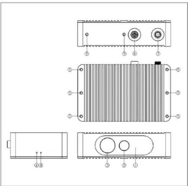
Femto Mega I Components
| Description Parts Functions | ||
| 1 Laser Module Projects laser onto the surface of the object being measured | ||
| 2 Depth Sensor Receives images of the measurement scene to calculate depth information | ||
| 3 Color Sensor Receives RGB images of the measurement scene, mainly used for instance segmentation, etc. | ||
| 4 Indicator Light Displays device operation status, refer to Table 3-2 for details | ||
| 5 Screw Holes Six M5 screw holes on the back of the device for mounting; can also be secured to a bracket using screws, then mounted through the bracket | ||
| 6 Ethernet Port 8-pin M12 connector for Gigabit Ethernet, used for data transmission and Power over Ethernet (PoE) capabilities | ||
| 7 12-pin Interface Provides power, I/O, RS232 serial port functions, etc., see Table 3-3 for details | ||


natural_image
Pure electrical circuit lines without any symbols

natural_image
Pure diagram of a mechanical component with three circular features and labeled parts (1, 2, 3), no text or symbols present.3.2 Product Interfaces
The connection interfaces of Femto Mega I camera are shown in the figure below.
8-pin Network Connector:

| Pin | Signal | Description |
| 1 TX_DA+ | Transmit Data+ | |
| 2 TX_DA- | Transmit Data- | |
| 3 RX_DB+ | Receive Data+ | |
| 4 RX_DB- | Receive Data- | |
| 5 B1_DD+ | Bi-directional Data+ | |
| 6 B1_DD- | Bi-directional Data- | |
| 7 B1_DC- | Bi-directional Data- | |
| 8 B1_DC- | Bi-directional Data+ | |
12-pin Connector:
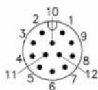
| Pin | Signal | Description | |
| 1 RS232-TX | RS232 | transmission | |
| 2 ISO-GND | Signal | ground | |
| 3 | DC-IN | Camera power (standard power cord, 3 and 4 combined) | |
| 4 DC-IN | |||
| 5 GND | Camera | power ground (standard power cord, 5 and 11 ground combined) | |
| 6 | NC | ||
| 7 | NC | ||
| 8 | NC | ||
| 8 VSYNC-OUT | I/O output | ||
| 8 R232-RX | RS232 | reception | |
| 8 GND | Camera | power ground (standard power cord, 5 and 11 ground combined) | |
| 8 VSYNC-IN | I/O input | ||
4. Software Development Kit (SDK)
Orbbec SDK is a flexible and modular platform for easy camera setup that runs on Linux/Windows with a rich set of APIs. It supports camera access; device setup and configuration; data stream reading, processing, and viewing; RGB-D registration; and frame synchronization.
Functions include:
- Access and control of camera devices
• Control of frame synchronization and alignment
• Acquisition of point cloud data - Orbbec Viewer for camera testing
Please check https://www.orbbec.com/developers/orbbec-sdk/ for the latest SDK.
5. Camera Setup and Operation
Packing List
• Orbbec Femto Mega I device
- 10 x M5 screws
Initialization and Operation
- Connect Femto Mega I via the cable to the host PC.
- Check the indicator on the camera and validate that all cameras are enumerated correctly in Windows device manager.
- Download the Orbbec SDK from https://www.orbbec.com/developers/orbbec-sdk/
- Validate that the cable can stream reliably on all sensors in the Orbbec Viewer, with the following settings:
• Depth camera: 640 x 576
- RGB Camera: 2160p
- If the camera is not responding or not being detected for any reason, please remove all cables from the camera and replug to the host PC to reset the camera state.
Connection
Method 1:
When using the POE connection, there is no need for any external power supply. Use the M12 connection on the camera to connect to a compatible POE switch or external computer.
Method 2:
Connect one end of the Ethernet cable to the industrial control computer's network port, and the other end to the 8-PIN network port of the industrial 3D camera. Connect one end of the power cable to the power switch, and the other end to the 12-PIN power port of the industrial 3D camera. (All cables and power switch connections are available as optional accessories)
Camera Setup and Operation: Continued from previous page
Power Switch Installation:
Pay attention to the following when using the power switch:
- Before using the product, be sure to read the product introduction and instructions first. Place the power supply in an enclosed power supply box to ensure electrical safety.
2 Before installation, be sure to check that the wiring labels on the power supply match the diagram. Use a conduit between connections to prevent contact between primary and secondary circuits. Cover the power ports to avoid electric shock and ensure safe use of the power supply.
3 Secure mounting: Place the power supply in an enclosed power supply box and fasten it inside the box to prevent the power supply from sliding. - When connecting, disconnect the input power. To ensure safety and minimize interference, ensure the ground terminal is reliably grounded.
5 It is recommended to add heat sink fins to the power supply box. Maximize contact between the housing and box for heat dissipation and longer power supply life.
6 Check to make sure that installation screws do not contact power supply board devices. Measure insulation resistance between the enclosure, input and output to avoid electric shock. - Before powering up after installation, check the connections at each terminal again to confirm correct input/output, AC/DC, positive/negative. Avoid reverse or incorrect connections.
- If the power supply fails, notify the company immediately. Describe the failure to facilitate troubleshooting and repair/replacement as needed

natural_image
Pure electrical circuit lines without any symbolsIndicators
| Number Device Status Indicator Light Status | |
| 1Device is starting up Red light slowly flashing, blue light off | |
| 2Device is normal, idle state Blue light steady, red light off | |
| 3Normal outflow Blue light slowly flashing, red light off | |
| 4No data flow from the optical module | Blue light flashing quickly, red light off |
| 5Firmware is being burned Red and blue lights quickly flashing alternately |
Temperature sensor and recording
The temperature of camera core components — including the CPU temperature, laser temperature, and IR sensor temperature — can be obtained through API commands.
6. Installation Guide
Use outside of the specified conditions could cause the device to fail and/or function incorrectly. These conditions are applicable for the environment immediately around the device under all operational conditions. When used with an external enclosure, active temperature control and/or other cooling solutions are recommended to ensure that the device is maintained within these ranges.
6.1 Installation Recommendations
- Avoid the application of external forces to the camera chassis during the installation process.
- Disassembling the chassis and mounting brackets will void the warranty.
6.2 Heat Dissipation
- Avoid any direct heat sources around the camera.
- Maximizing the space inside the external housing may help lower the operating temperature.
6.3 Transmittance Requirements
Transmittance requirements for the front cover protection lens of Femto Mega 3D camera are listed as follows:
- RGB transmittance: 835\~865nm T_min > 85%, 800\~960nm T_ave > 88% and 400\~700nm T_ave > 85%
- RX transmittance: 420\~680nm T _min > 97%
- Flatness of front cover lens material: < 0.005mm.
- Glass is recommended.
Any protective glass placed in front of the camera lens must meet the above requirements
6.4 Cable Design Guide
The default length for power cables and network cables is 5 meters, while the default length for AC power cables is 2 meters. The cable type and length can be modified to meet actual requirements.
6.5 Mounting the Camera using the Threaded Hole
Use M5 screws to mount the camera.
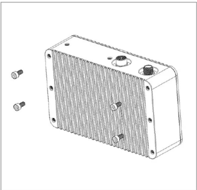
natural_image
Technical line drawing of a rectangular electronic component with multiple screw holes and a central screw (no text or symbols)7. Product Drawings

Product Dimensions
8. Field of View Illustration
The image below shows the depth and RGB camera field-of-view, or the angles that the sensors "see". This diagram shows the RGB camera in a 4:3 mode.

This image demonstrates the camera's field-of-view as seen from the front at a distance of 2000 mm. When depth is in NFOV mode, the RGB camera has better pixel overlap in 4:3 than 16:9 resolutions.


9. Multi-Camera Synchronization
Advantages of multi-camera setup
- Increase camera coverage in a given space and fill in the occlusions where a single camera may have blind spots.
• Capture multiple images of the same scene and scan objects from different angles. - Increase the effective frame rate (FPS).
A multi-camera and multi-sensor network can be designed by following the 12-pin connector guide and using a matching cable. Recommended minimum delay setting is 160us (please follow the instructions in the SDK)
10. Safety and Handling
10.1 Safety Precautions
- Follow the camera operation instructions. Improper operation may cause damage to internal components.
- Do not drop or subject the camera to external force.
- Do not attempt to modify the camera. Modifications may cause permanent damage or inaccuracies.
- The camera temperature may increase during long periods of continuous usage.
- Do not touch the lens. Fingerprints on the lens may affect image quality.
- Keep the product beyond the reach of children or animals to avoid accidents.
- If the camera is not recognized by the computer, check if the cable meets the power/data transfer requirements and reinsert the USB for reconnection.
- This product uses a Class 1 laser. Looking at the laser for more than 20s is not recommended.
10.2 Cleaning
To clean the camera body, use a clean, soft cloth to wipe away dust and debris. To remove stains from the lens, carefully wipe with a clean, soft, lint-free cloth moistened with lens cleaning solution to avoid scratching the camera.
- Do not use alcohol, gasoline, kerosene, or other corrosive or volatile solvents to clean the camera.
- Do not use pressure washers or hoses to spray the camera.
10.3 Storage
This product has an IP65 protection rating, which prevents dust from entering the camera and affecting its functionality. However, submerging the camera in water or exposing it to high humidity environments may cause malfunctions. When not in use, store the camera in a cool, dry, and well-ventilated indoor location. Avoid leaving the camera outdoors for extended periods to prevent damage from rain, snow, or other harsh conditions. The camera's storage temperature range is -20 to 60°C (-4 to 140°F).
- Disconnect the power supply before storing the camera
- Do not point the lens directly at the sun; avoid exposing the lens to strong light sources for extended periods.
11. Glossary of Terms
| Term Description | |
| D2C | Depth to Color function maps each pixel on a depth map to the corresponding color image according to the intrinsic and extrinsic parameters of depth camera and color camera. |
| Depth | Depth video streams are like color video streams except each pixel has a value representing the distance away from the sensor instead of color information. |
| Depth Camera | Includes the external interface and the depth imaging module, which is generally composed of the infrared projector, the infrared camera, and the depth computing processor. |
| FOV | Field of View (FoV) describes the angular extent of a given scene that is captured by a camera, which can be measured in horizontal, vertical, or diagonal. |
| I2C | I2C bus refers to a kind of simple bidirectional two-wire synchronous serial bus developed by Philips. It can be used for transferring information among devices connected to the bus with two wires. |
| IR Camera | Infrared camera. |
| IR Flood | IR floodlights are used to illuminate the environment. |
| ISP | Image signal processor, which is used for image post-processing. |
| MIPI | Mobile Industry Processor Interface (MIPI) is an open standard and specification formulated by the MIPI Alliance for mobile application processors. |
| PCBA | Circuit board that includes the depth computing processor, memory, and other electronic devices. |
| Point Cloud | A point cloud is a discrete set of data points in space. |
| SoC | System on Chip, an integrated circuit (IC) that integrates all components of a computing system. |
| TBD | To Be Determined. In the context of this document, information will be available in a later revision. |

natural_image
Abstract pattern of blue circles arranged in a symmetrical radial shape (no text or symbols)ORBBEC
Copyright 2023 Orbbec Inc. All rights reserved. The product described may contain defects or errors or deviation from published specifications. Contact your sales representative to obtain the latest Orbbec 3D product specifications. Orbbec is not responsible for any users infringing on third party copyright or other rights in use of Orbbec products. In addition, Orbbec does not assume any liability for damages or any losses resulting from the use of this product. All information provided here is subject to change without notice.

- Product Brief
- Product Overview
- Product Features
- Product Characteristics
- Performance
- Programmability
- Packaging
- Product Specifications
- Product Information
- Product Interfaces
- Software Development Kit (SDK)
- Functions include:
- Camera Setup and Operation
- Packing List
- Initialization and Operation
- Connection
- Method 1:
- Method 2:
- Power Switch Installation:
- Pay attention to the following when using the power switch:
- Temperature sensor and recording
- Installation Guide
- Installation Recommendations
- Heat Dissipation
- Transmittance Requirements
- Cable Design Guide
- Mounting the Camera using the Threaded Hole
- Product Drawings
- Field of View Illustration
- Multi-Camera Synchronization
- Advantages of multi-camera setup
- Safety and Handling
- Safety Precautions
- Cleaning
- Storage
- Glossary of Terms
- ORBBEC
Brand : Orbbec
Model : Femto Mega I
Category : 3D Printer