
CXR-210 - Audio Equipment HK AUDIO - Free user manual and instructions
Find the device manual for free CXR-210 HK AUDIO in PDF.


| Product Type | Passive 2-way loudspeaker |
| System | Bass reflex |
| Woofer | 10" (254 mm) neodymium |
| Tweeter | 1" (25 mm) compression driver |
| Power Handling (RMS) | 400 W |
| Power Handling (Program) | 800 W |
| Impedance | 8 ohms |
| Frequency Range (-10 dB) | 55 Hz - 20 kHz |
| Maximum SPL | 130 dB |
| Dimensions (H x W x D) | 560 x 340 x 300 mm |
| Weight | 16.5 kg |
| Power Supply | Passive, requires external amplifier |
| Enclosure Material | Birch plywood |
| Grille | Powder-coated steel |
| Connectors | 2 x SpeakON NL4 |
| Rigging Points | 16 x M10 threaded inserts |
| Pole Mount | 35 mm socket |
| Applications | Live sound, DJ, PA systems |
| Maintenance | Clean with dry cloth; check connections regularly |
| Safety | Do not expose to moisture; use stable stands; professional installation recommended |
Frequently Asked Questions - CXR-210 HK AUDIO
User questions about CXR-210 HK AUDIO
0 question about this device. Answer the ones you know or ask your own.
Ask a new question about this device
Download the instructions for your Audio Equipment in PDF format for free! Find your manual CXR-210 - HK AUDIO and take your electronic device back in hand. On this page are published all the documents necessary for the use of your device. CXR-210 by HK AUDIO.
USER MANUAL CXR-210 HK AUDIO
Mounting instructions
- Important notes on safety and use....2
- Introduction 4
- Dimensions & technical specifications....4
- ICF....4
- Mounting the CXR-210 4
- Angle table....6
- Intended use....6
Montageanleitung
Welcome to the HK Audio family!
Thank you for choosing a brand-name product made by our company. It was engineered and built with the greatest care so it will serve you well for many tomorrows to come.

Be sure to read these operating instructions carefully and keep them for future
reference. Here's wishing you the best sound at every occasion!
Your HK Audio Team
Warranty
Register each individual HK Audio product – you'll then get a free 5-year warranty! Register online with ease at www.hkaudio.com.

http://warranty.hkaudio.com
The warranty registration is only valid if made within 30 days of the date of purchase.
HK Audio
Technical service
Postfach 1509
66595 St. Wendel, Germany
Fax: +49 6851 905 100
Important notes on safety and use! Please read before use!

This symbol, wherever it appears, alerts to important operating and maintenance actions in the accompanying literature. Read manual.

This symbol, wherever it appears, tells take care! Hot surface! To prevent burns you not touch.

All electrical and electronic products including batteries should be disposed of separately from the municipal waste stream via designated collection facilities appointed by the government or the local authorities.
Safety instructions

The suitability of the supporting structure, load-bearing capacity of the structure, as is the suitability and dimensioning of the moment points must be ensured before ing the system.
"Information on the load-bearing capacity of structures generally refers to static loads in a vertical direction (without dynamic load components).
Attachment points on the supporting structure are regarded as interfaces to the structure and must be able to safely absorb loads. Attachment points are defined positions on the supporting structure, e.g. intersections on truss girders or eyelets permanently attached to the supporting structure. Below this interface to the structure, all elements in the load line are designed to be intrinsically safe. In addition, single-fault safety measures are implemented where necessary. The attachment of loads to structures is only permitted if the operator can provide clear information on the nominal load capacity of the attachment points. In particular, these are:
• Size of the rated load capacity
- Rated load capacity in relation to the direction of force
Only the attachment points approved by the operator may be used. The operator's specifications for the load capacity of the attachment points must not be exceeded either during assembly and dismantling or during operation. A load measuring device can be used for this purpose. When planning an event or production, dynamic forces, possible incident-induced loads and additional loads during operation as well as during assembly and dismantling must be taken into account in addition to the dead loads. For example, additional forces arise due to inclined bracing and acceleration of loads as well as jerky stopping of moving loads." (Source: DGUV Information 215-313).
In addition, the respective national law must be observed.

The suitability and sufficient load-bearing activity of the components used in connection to the system in the load line (e.g. shackles other slings, lanyards, tensioning elements, load-bearing equipment) must be used for the application. Persons are only suited to stand under the system if all (other) elements in the load line are designed to be physically safe. Elements that are not expressly used for use above persons may be suitable or certain circumstances if they are loaded to maximum of half the specified load capacity. Slings made of synthetic fi bres may not be over people without additional securing condition, the respective national law must be used. The operator is responsible for maintaining the safe operating condition and for suitability of the elements used in the load

The operator must arrange for the ving inspections to be carried out:
- Inspection of the components of the rigging hardware (fl light rail, the rigging hardware attached to the speaker cabinet and all other components used for rigging) before first use and thereafter periodically by a qualified/competent person to ensure that they are in a safe operating condition.
- After particular damage-causing events (e.g. crash, overloading of system components), the operator must arrange for an extraordinary inspection of the affected components by a competent person.
The applicable national laws and regulations must be observed with regard to the type, deadlines and scope of the inspections. The operating conditions must be taken into account.
However, the scope of testing for the inspection before initial commissioning, periodic inspection and inspection after particular damage-causing events includes at least the following criteria:
Condition, damage, cracks, deformation, corrosion, functionality/mobility, wear, fastening and securing of detachable connections, effectiveness of interlocks, completeness of connecting elements, legibility of type plate/permissible load capacity.
The inspection interval for the periodic inspection must not be more than one year. The inspections must be documented.
- The components of the rigging hardware (flight rail, the rigging hardware attached to the speaker cabinet and all other components used for rigging) must be checked for visible defects, wear, functionality, apparent operational safety and legibility of markings by a person instructed with regard to this inspection at least before each use.
If defects are found that impair safety or if the markings can no longer be clearly identified, the work equipment must be withdrawn from further use until it has been properly repaired.

The secondary safety devices (safeties) be attached to the following points on the high units: - Suitable attachment points are things for attaching the shackles - The shipment of secondary safety devices to parts of mid/high units other than thoseioned here is prohibited.

Direct attachment (without flight rail) only be carried out as described in these actions. To tilt the lifted system using a, only double-stranded slings that are also lined for edge loading or equipped with edge action may be used. It must be ensured that hackles attached under the mid/high unit align freely and are not subjected to diagonal Attach the sling to the mid/high units using side lugs in the centre of the speakers – it is laden to attach it in the intermediate position (between two speakers).
The components used in connection with the attachment or rigging of the system (e.g. hoists, slings, lanyards) must be inspected periodically by competent persons, taking into account the ambient conditions, the respective manufacturer's specifications and the respective national regulations, and before each installation by instructed persons.
The operator must carry out a risk assessment for the respective use of the system. Among other things, the suitability of the components used, the deadlines and scope of the inspection of the work equipment and the suitability of the personnel deployed must be checked. With regard to the assembly and dismantling of the systems, the need for measures such as barriers and coordination of the trades involved must also be determined on a case-by-case basis. Conditions of use and interactions with the working environment must be taken into account.
The fl own system must be secured against twisting and unintentional movement in the event of wind. This is done by attaching safety cords to the openings for attaching the shackles.
Do not use in windy conditions with impermissible wind speeds. The system must be removed or lowered and secured by the time wind force 8 or a gust wind speed of 20 m/s is reached. Measures must be planned, coordinated and carried out professionally.
Only slings and hoists certified by their manufacturer as conforming to 2006/42/EC (outside the scope of 2006/42/EC of equivalent quality in accordance with the respective national regulations) may be used in rigging operations.
Only personnel who are trained and qualified for the respective task may be deployed. This applies to assembly, dismantling, operation, maintenance, troubleshooting, repair and inspection.
To create a system consisting of several mid/high units for rigging operation, these must first be fully connected to each other on the top side before lifting. The system may then only be lifted high enough for the connections to be made on the underside. Only once the mid/high units have been fully connected to each other can the system be lifted further.
The connections of the individual components of the flight rail are self-locking and may only be loosened/replaced by the manufacturer or by a specialist company authorised by the manufacturer.
To avoid swaying when lifting loads using a hoist, make sure the load's centre of gravity is vertically below the hoist.
Suitable and sufficient lighting must be provided for assembly/dismantling, cleaning, troubleshooting, maintenance and repair. National regulations must be observed in this respect.
Materials must be stored securely on a sufficiently stable surface. Traffic routes, in particular escape and rescue routes, as well as fi re extinguishing equipment, must always be kept clear at the place of use.
Operating the system outdoors, including any work carried out on the system, is prohibited during thunderstorms. If there is a thunderstorm on the way when used outdoors: Stop work, do not touch any conductive parts, do not stand under/near raised systems. If possible, go to a safe room/area. Weather forecasts must be continuously monitored.
Read these instructions. Keep these instructions. Follow all warnings and instructions marked on the product and in this manual.
- Do not place objects containing liquid on the product - vases, glasses, bottles etc.
- Clean only with dry cloth.
- Do not remove any covers or sections of the housing.
• Refer all servicing to qualified service personnel. Servicing is required when the unit has been damaged in any way, such as: -
If liquid has been spilled or objects have fallen into the product.
-
If the product does not operate normally when the operating instructions are followed.
-
If the product has been dropped or the cabinet has been damaged.
-
Do not install near heat sources such as radiators, heat registers, stoves or other devices that produce heat.
- Do not place naked flame sources, such as lighted candles on the product.
- Use only with the cart, stand, tripod, bracket or table specified by the manufacturer or sold with the product.
- When a cart is used, use caution when moving the cart/product combination to avoid injury from tip-over.
- Use only accessories recommended by the manufacturer, this applies for all kind of accessories, for example protective covers, transport bags, stands, wall or ceiling mounting equipment.
In case of attaching any kind of accessories to the product, always follow the instructions for use, provided by the manufacturer. Never use fixing points on the product other than specified by the manufacturer.
- No objects should be inserted through the housing openings.
- This device is capable of producing sound pressure levels of more than 90 dB.
This could lead to permanent hearing damage! Exposure to extremely high noise levels may cause a permanent hearing loss.
Wear hearing protection if continuously exposed to such high levels.
- The manufacturer only guarantees the safety, reliability and efficiency of this product if:
- Assembly, extension, re-adjustment, modifications or repairs are carried out by the manufacturer or by persons authorized to do so.
- The unit is used in accordance with the operating instructions.
• This product is optimized for use with music and voice content.
Using this product with sine wave, square wave or other kind of measuring signals at higher level may lead to severe damage of the product.
Introduction
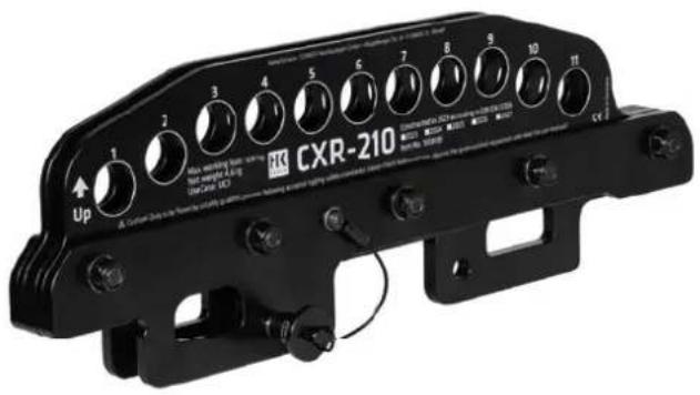
The CXR-210 is the optional flight & tilting rail for precise angling of the CONTOUR X 210 LT. It allows a single speaker to be angled up to a horizontal array of four speakers at just one mounting point with 44 different angle options.
Dimensions & technical specifications

Made from: 1.0976 (S355MC steel)
Weight: 4.6 kg
ICF Integrated Cluster- & Flyware
The CONTOUR X 210 LT is equipped with integrated cluster & fl yware (ICF), allowing several speakers to be connected directly to form a horizontal array, and the speakers to be fl own without additional accessories.
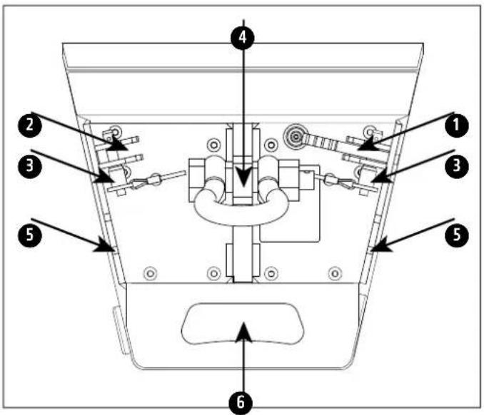
Upper ICF
1 Flap for connecting the speakers to form a horizontal array
2 Insertion opening for connector flap of an additional speaker
3 QRP (Quick Release Pin) for securing the fl aps when parked and when connected
4 Pick point for attaching a shackle for flying as a single speaker and in a horizontal triple array
5 Pick point for attaching a shackle for flying in a horizontal array of two or four.
Flying without the CXR-210 tilt bracket results in the following angles:
Single: 6°
Cluster of 2: 8°
Cluster of 3: 2°
Cluster of 4:1°
6 Rear access
Top view CONTOUR X 210 LT
Lower ICF
1 Flap for connecting the speakers to form a horizontal array
2 Insertion opening for connector flap of an additional speaker
3 QRP (Quick Release Pin) for securing the flaps when parked and when connected
4 36mm stand flange mounting opening for stands for individual application
5 Lower pick point for attaching a shackle (also suitable for securing the CONTOUR X 210 LT)
6 Rear access. This is also used to securely attach a sling for tilting without using the CXR-210 flight rail

Bottom view CONTOUR X 210 LT
Mounting the CXR-210 flight rail
Flying the CONTOUR X 210 LT in a horizontal array with the CXR-210 rigging rail
- Only move the speakers with the assistance of another person, to avoid possible injuries
- Place the speakers connected to form a horizontal array on a flat surface (for clustering, see instructions on connecting the speakers to form a horizontal array)
- The CONTOUR X 210 LT has a mounting point for attaching the CXR-210 in the centre of the upper ICF, as well as on the side edge of the upper ICF
- The mounting point in the centre of the ICF must be used to fly a single speaker or a horizontal array of three. The CXR-210 flight rail is designed to fit into the intended mount in one direction only. After attaching the CXR-210, the QRP must be pushed into the openings provided in the flight rail to secure it until it clicks into place with an audible click

- To fly a horizontal array of two and a horizontal array of four, the mounting point between the connected speakers must be used. The CXR-210 flight rail is designed to fit into the intended mount in one direction only.
After attaching the CXR-210, the QRP must be pushed into the openings provided in the flight rail to secure it until it clicks into place with an audible click

- Connect the horizontal array at the desired angle (see table with 44 angle options) to the designated pick point using a shackle, insert the threaded bolt and secure by tightening the nut. Secure the connection with the spring pin (split pin) to further secure it
- Raise the horizontal array to working height (approx. 1.50 m) using the chain hoist
- Slide the QRPs on the underside (lower ICF) for securing the flaps into the openings provided in the flaps on both sides of the respective speakers until they click into place with an audible click

- Pull the horizontal array to the desired height

Heads Up: Suitable secondary securing devices (safeties) must always be used. A securing element (safety) must be installed in such a way that it does not allow any fall distance. If a fall distance is unavoidable, it must be minimised as far as possible. A secondary securing device can only be omitted if all components in the load line are intrinsically safe, can only be released with tools and are secured against self-release.

Heads Up: If the individual speaker or the cluster is raised or lowered,
it is prohibited for people to stand underneath it!
Angle table
Please read these instructions carefully before starting assembly and always have them available when working on or with the system!
Use
• Intended use for the rigging hardware
The rigging hardware, consisting of the ICF (Integrated Cluster & Flyware) and CXR-210 rigging rail, is intended for permanent or temporary "flown" (suspended) installation of the CONTOUR X 210 LT speakers from HK Audio, in accordance with the manufacturer's specifications.
Any use other than that described here is considered improper use. The manufacturer is not liable for any resulting damage from this. Intended use also includes observing all instructions in the operating instructions and carrying out all necessary inspection and maintenance work. The applicable national laws and regulations must be observed. The configuration and load conditions must be adjusted using the EASE Focus 3 software before installation.
The system must be assembled and dismantled as described in the operating instructions.
The connections must be made properly and fully: two mounting points per speaker pair (one in the upper ICF and one in the lower ICF) for clustering via the flaps and the quick release pins.
• Warranty and liability
HK Audio is not responsible for damage caused by improper use or by contravention of applicable law or the safety instructions in the operating instructions. Warranty and liability claims for personal injury and damage to property are excluded if they are due to one or more of the following causes:
- Failure to observe the instructions given in the operating instructions may invalidate claims under product liability and warranty claims
- Improper use of the rigging hardware (ICF or ICF in combination with the CXR-210 rigging rail)
- Disregarding the instructions in the operating instructions regarding transport, storage, commissioning, installation, dismantling, operation, maintenance, repair, inspection and disposal of the system components.
- Unauthorised structural changes to parts of the system
- Unauthorised changes to the parameters specified in the operating instructions
Unauthorised or improperly performed repairs
Intended use of the rigging rail
Used as part of the rigging hardware, the rigging rail is intended for the permanent or temporary "flown" (suspended) installation of one to a maximum of four HK Audio CX-210 LT mid/high units.
The rigging hardware is intended for use in hoist operation as well as for assembly without a hoist. When permanently installed without a hoist, the product is not used as a lifting accessory within the meaning of the Machinery Directive. In other words, this type of application is not fully considered in this risk assessment. This only considers the possibility of interactions, e.g., possible damage to the rigging hardware during assembly without hoist operation, which may have an impact during subsequent operation using hoists.
Holding loads above persons is considered to be in accordance with the intended use.
Any use other than that described above is prohibited.
Reasonably foreseeable misuse.
The following applications are considered non-intended and are therefore prohibited:
- Any use other than that specified as intended is generally not permitted
- Use of the rigging hardware for flown operation of non-system speakers or other loads
• Overloading the rigging hardware or individual components of the rigging hardware, overloading any hoist used, overloading slings used such as shackles, ropes, chains. - Rigging a cluster consisting of more than 4 mid/high units
- Incorrect or incomplete connection of the components*
- The use of non-system components to connect the mid/high units to each other
• Overloading and/or instability of the supporting structure to which the hoist/system is attached - Lifting loads with the centre of gravity not perpendicular to the hoist's attachment point
- Use of unsuitable or unauthorised components*
- Use of faulty components*
- Use outside the permissible temperature ranges
- Use at unauthorised wind speeds
• Influence of aggressive media on the components' material*
• Operation in areas in which the formation of a hazardous explosive atmosphere cannot be ruled out - Transport or storage of the components where they are exposed to damaging influences (e.g. heat, moisture, aggressive media, high mechanical forces)
• Unauthorised changes to system components - Improper repairs to system components
- Moving loads over people
* concerns components of the rigging harness as well as components used with it, e.g. hoist, slings, parts of the supporting structure
Storage, maintenance and repair of rigging hardware
- Storage, putting away when not in use
If the rigging hardware is not in use, it must be protected from damage-causing influences.
- Maintenance
Wear parts or standard parts that are easy to replace can be replaced by the user with the express approval of the manufacturer and in accordance with the manufacturer's instructions. Original spare parts must always be used. Screws and screw connections must be tightened if necessary.
- Cleaning
Only mild soapsuds or similar cleaning agents may be used to clean the rigging hardware. Protect the components from aggressive media such as acids or strong alkaline solutions.
- Repairs
The manufacturer shall decide whether deformed parts of the load suspension device can be repaired. All welding and repair work on the load suspension device is carried out by the manufacturer.
| Wind force(Beaufort scale) | Speed (m/s) Description Perceptible effects | ||
| 0 v < 0.51 | Galm No air movement, smoke rises vertically | ||
| 10.51 ≤ v < | 2.06 Light air | barely noticeable, smoke drifts slightly, wind vanes motionless | |
| 22.06 ≤ v < | 3.60 Light breeze Leaves | ustle, wind felt on face | |
| 33.60 ≤ v < | 5.66 Gentle breeze | Leaves and small twigs moved; light flags extended | |
| 45.66 ≤ v < | 8.23 Moderate breeze | Small branches moved, loose paper raised from the floor | |
| 58.23 ≤ v < | 11.32 Fresh breeze | Larger trees and branches moved, wind clearly audible | |
| 6 | 11.32 ≤ v < 14.40 | Strong breeze | Large branches moved, whistling heard in wire ropes and telegraph wires |
| 7 | 14.40 ≤ v < 17.49 High wind | Whole trees sway, resistance felt when walking against the wind | |
| 8 | 17.49 ≤ v < 21.09 | Gale | Large trees moved, shutters are opened, twigs break off trees, considerable inconvenience felt when walking |
| 9 | 21.09 ≤ v < 24.69 Severe gale | Branches break, bricks are lifted, garden furniture is knocked over and blown away, considerable inconvenience felt when walking | |
| 10 | 24,69 ≤ v < 28,81 | Storm | Trees are uprooted, garden furniture is blown away, major damage to buildings |
| 11 | 28.81 ≤ v < 32.92 | Violent storm | Heavy gusts, roofs are blown off, cars are thrown off track, thick walls are knocked over, walking is impossible |
| 12 | v < 32.92 | Hurricane-force | Severe storm damage, devastation |
Technical data of the CONTOUR X 210 LT rigging hardware
• Maximum load capacity:
CXR-210 rigging rail 160 kg (max. working load)
Coefficient used for static testing: 3x
Permissible ambient temperature during operation: -10° to +60°C
Permissible wind speed: <8 on the Beaufort scale, gust speed <20 m/s
• Maximum number of flown speakers
A maximum of 4 CONTOUR X 210 LT units are permitted in a cluster for the CXR-210. For the ICF (Integrated Cluster & Flyware) the maximum is 4 units. The rigging mechanics are designed for standard clusters. Please refer to the examples in the overview on page 20.
When determining the flown loads, please note that the weights of motors, cables and other slings must be added!
- Modifying the CONTOUR X 210 LT rigging hardware
No design modifications may be made without the manufacturer's authorisation. This applies in particular to welding on load-bearing parts. Conversion measures require the written consent of the manufacturer.
• Original HK Audio accessories
Only use original HK Audio accessories. The manufacturer's product liability shall not apply if third-party parts are used! Assembly must be carried out in accordance with the rigging manual! Keep all documents relating to the system in a safe place!
ICF Integrated Cluster- & Flyware
- MOUNTING INSTRUCTIONS
- MONTAGEANLEITUNG
- WELCOME TO THE HK AUDIO FAMILY
- WARRANTY
- HK AUDIO
- IMPORTANT NOTES ON SAFETY AND USE! PLEASE READ BEFORE USE
- SAFETY INSTRUCTIONS
- INTRODUCTION
- ICF INTEGRATED CLUSTER- & FLYWARE
- UPPER ICF
- LOWER ICF
- MOUNTING THE CXR-210 FLIGHT RAIL
- FLYING THE CONTOUR X 210 LT IN A HORIZONTAL ARRAY WITH THE CXR-210 RIGGING RAIL
- USE
- INTENDED USE FOR THE RIGGING HARDWARE
- WARRANTY AND LIABILITY
- INTENDED USE OF THE RIGGING RAIL
- REASONABLY FORESEEABLE MISUSE
- STORAGE, MAINTENANCE AND REPAIR OF RIGGING HARDWARE
- STORAGE, PUTTING AWAY WHEN NOT IN USE
- MAINTENANCE
- CLEANING
- REPAIRS
- TECHNICAL DATA OF THE CONTOUR X 210 LT RIGGING HARDWARE
- MAXIMUM LOAD CAPACITY
- MAXIMUM NUMBER OF FLOWN SPEAKERS
- MODIFYING THE CONTOUR X 210 LT RIGGING HARDWARE
- ORIGINAL HK AUDIO ACCESSORIES
Brand : HK AUDIO
Model : CXR-210
Category : Audio Equipment