
Cadis - Speaker HK AUDIO - Free user manual and instructions
Find the device manual for free Cadis HK AUDIO in PDF.


| Product Type | Line Array System (Mid/High Enclosure + Subwoofer) |
| Model | CADIS (CAD 208 Mid/High, CAD 115 Sub) |
| CAD 208 Drivers | 2x 8" woofers, 2x 1" HF drivers with CD horns |
| CAD 208 Power Handling | 250 W RMS, 500 W program (AES, 6 dB crest) |
| CAD 208 Impedance | 8 ohms nominal |
| CAD 208 Frequency Range | 75/100 Hz - 18 kHz (±3 dB, depending on controller) |
| CAD 208 SPL (1W@1m) | 95 dB full-space, 101 dB half-space |
| CAD 208 Max SPL | 136 dB @10% THD half-space (1m, with 4 enclosures) |
| CAD 208 Dimensions (W x H x D) | 57.8 cm x 23.8 cm x 37.3 cm (22.75" x 9.38" x 14.69") |
| CAD 208 Weight | 17.5 kg (38.6 lbs) |
| CAD 115 Subwoofer Driver | 1x 15" neodymium woofer |
| CAD 115 Sub Power Handling | 600 W RMS (AES, 6 dB crest) |
| CAD 115 Sub Impedance | 8 ohms |
| CAD 115 Sub Frequency Range | 47 Hz - 150 Hz (±3 dB, depending on controller) |
| CAD 115 Sub SPL (1W@1m) | 96 dB full-space, 102 dB half-space (50-200 Hz) |
| CAD 115 Sub Max SPL | 128 dB @10% THD half-space (1m, 60-150 Hz) |
| CAD 115 Sub Dimensions (W x H x D) | 58.3 cm x 57.3 cm x 64 cm (22.95" x 22.56" x 25.20") |
| CAD 115 Sub Weight | 38 kg (83.8 lbs) |
| Housing Material | CAD 208: Polyamide resin reinforced with glass fibers; CAD 115 Sub: 18-mm birch plywood with acrylic enamel |
| Connectors | 2x Speakon NL4 (input/through) per enclosure; optional barrier strip or PG glands |
| Rigging Hardware | Integrated on CAD 208 with 3 pick-points; CAD 115 Sub with 4 rigging rails; standard rigging frame (max load 400 kg) |
| Controller | FIRNET Linear Phase Controller (optional, for system optimization) |
| Recommended Amplifier | HK AUDIO VX 2400 or Lab.gruppen FP 10000Q |
| Cleaning | Clean only with a dry cloth. Do not use liquid cleaners. |
| Spare Parts | Use only original HK AUDIO parts: 8" woofer (9940261), 15" woofer (9940184), 1" HF driver (9940173), voice coil (9940190), etc. |
| Safety Certifications | Complies with EMC Directive 2004/108/EC and Low Voltage Directive 2006/95/EC; TÜV certified rigging system |
Frequently Asked Questions - Cadis HK AUDIO
User questions about Cadis HK AUDIO
0 question about this device. Answer the ones you know or ask your own.
Ask a new question about this device
Download the instructions for your Speaker in PDF format for free! Find your manual Cadis - HK AUDIO and take your electronic device back in hand. On this page are published all the documents necessary for the use of your device. Cadis by HK AUDIO.
USER MANUAL Cadis HK AUDIO
Important Safety Instructions Before connecting, read instructions
Important Advice on Safety! Please read before use and keep for later use!
- Read all of these instructions!
- Save these instructions for later use!
- Follow all warnings and instructions marked on the product!
- Do not use this product near water, i.e. bathtub, sink, swimming pool, wet basement, etc.
- Do not place this product on an unstable cart, stand or table. The product may fall, causing serious damage to the product or to persons!
- Slots and openings in the cabinet and the back or bottom are provided for ventilation; to ensure reliable operation of the product and to protect it from overheating, these openings must not be blocked or covered. This product should not be placed in a built-in installation unless proper ventilation is provided.
- This product should not be placed near a source of heat such as a stove, radiator, or another heat producing amplifier.
- Use only the supplied power supply or power cord. If you are not sure of the type of power available, consult your dealer or local power company.
- Do not allow anything to rest on the power cord. Do not locate this product where persons will walk on the cord.
- Never break off the ground pin on the power supply cord.
- Power supply cords should always be handled carefully. Periodically check cords for cuts or sign of stress, especially at the plug and the point where the cord exits the unit.
- The power supply cord should be unplugged when the unit is to be unused for long periods of time.
- If this product is to be mounted in an equipment rack, rear support should be provided.
- This product should be used only with a cart or stand that is recommended by HK AUDIO®.
- Never push objects of any kind into this product through cabinet slots as they may touch dangerous voltage points or short out parts that could result in risk of fire or electric shock. Never spill liquid of any kind on the product.
- Do not attempt to service this product yourself, as opening or removing covers may expose you to dangerous voltage points or other risks. Refer all servicing to qualified service personnel.
• Clean only with dry cloth. - Do not defeat the safety purpose of the polarized or grounding-type plug. A polarized plug has two blades with one wider than the other. A grounding type plug has two blades and a third grounding prong. The wide blade or the third prong are provided for the safety. If the provided plug does not fit into your outlet, consult an electrician for replacement of the obsolete outlet.
- Place the product always in a way that the mains switch is easily accessible.
- Unplug this product from the wall outlet and refer servicing to qualified service personnel under the following conditions:
- When the power cord or plug is damaged or frayed.
- If liquid has been spilled into the product.
• If the product has been exposed to rain or water. - If the product does not operate normally when the operating instructions are followed.
- If the product has been dropped or the cabinet has been damaged.
- If the product exhibits a distinct change in performance, indicating a need of service!
- Adjust only these controls that are covered by the operating instructions since improper adjustment of other controls may result in damage and will often require extensive work by a qualified technician to restore the product to normaloperation.
- Exposure to extremely high noise levels may cause a permanent hearing loss.
- Individuals vary considerably in susceptibility to noise induced hearing loss, but nearly everyone will lose some hearing if exposed to sufficiently intense noise for a sufficient time. The U.S. Government's Occupational Safety and Health Administration (OSHA) has specified the following permissible noise level exposures:
- According to OSHA, any exposure in excess of the above permissible limits could result in some hearing loss.
- Ear plug protectors in the ear canals or over the ears must be worn when operating this amplification system in order to prevent a permanent hearing loss if exposure is in excess of the limits as set forth above. To ensure against potentially dangerous exposure to high sound pressure levels, it is recommended that all persons exposed to equipment capable of producing high sound pressure levels such as this amplification system be protected by hearing protectors while this unit is in operation.
- Fuses: Replace with IEC 127 (5x 20 mms) type and rated fuse for best performance only.
Duration Per Day In Hours Sound LeveldBA, Slow Response
| 8 | 90 | |
| 6 | 92 | |
| 4 | 95 | |
| 3 | 97 | |
| 2 | 100 | |
| 11/2 | 102 | |
| 1 | 105 | |
| 1/2 | 110 | |
| 1/4 | or less | 115 |
TO PREVENT THE RISK OF FIRE AND SHOCK HAZARD, DO NOT EXPOSE THIS APPLIANCE TO MOISTURE OR RAIN. DO NOT OPEN CASE; NO USER SERVICE-ABLE PARTS INSIDE. REFER SERVICING TO QUALIFIED SERVICE PERSONNEL.
- The unit has been built by HK AUDIO® in accordance with IEC 60065 and left the factory in safe working order. To maintain this condition and ensure non-risk operation, the user must follow the advice and warning comments found in the operating instructions. The unit conforms to Protection Class 1 (protectively earthed).
- HK AUDIO® ONLY GUARANTEE THE SAFETY, RELIABILITY AND EFFICIENCY OF THE UNIT IF:
- Assembly, extension, re-adjustment, modifications or repairs are carried out by HK AUDIO® or by persons authorized to do so.
- The electrical installation of the relevant area complies with the requirements of IEC (ANSI) specifications.
• The unit is used in accordance with the operating instructions. - The unit is regularly checked and tested for electrical safety by a competent technician.
WARNING:
- If covers are opened or sections of casing are removed, except where this can be done manually, live parts can become exposed.
- If it is necessary to open the unit this must be insulated from all power sources. Please take this into account before carrying out adjustments, maintenance, repairs and before replacing parts.
- The appliance can only be insulated from all power sources if the mains connection is unplugged.
- Adjustment, maintenance and repairs carried out when the unit has been opened and is still live may only be performed by specialist personnel who are authorized by the manufacturer (in accordance with VBG 4) and who are aware of the associated hazards.
- Loudspeaker outputs which have the IEC 417/5036 symbol (Diagram 1, below) can carry voltages which are hazardous if they are made contact with. Before the unit is switched on, the loudspeaker should therefore only be connected using the lead recommended by the manufacturer.
- Where possible, all plugs on connection cables must be screwed or locked onto the casing.
- Replace fuses only with IEC127 type and specified ratings.
- It is not permitted to use repaired fuses or to short-circuit the fuse holder.
- Never interrupt the protective conductor connection.
- Surfaces which are equipped with the "HOT" mark (Diagram 2, below), rear panels or covers with cooling slits, cooling bodies and their covers, as well as tubes and their covers are purposely designed to dissipate high temperatures and should therefore not be touched.
- High loudspeaker levels can cause permanent hearing damage. You should therefore avoid the direct vicinity of loudspeakers operating at high levels. Wear hearing protection if continuously exposed to high levels.
MAINS CONNECTION:
• The unit is designed for continuous operation.
• The set operating voltage must match the local mains supply voltage.
- The unit is connected to the mains via the supplied power unit or power cable.
- Power unit: Never use a damaged connection lead. Any damage must be rectified by a competent technician.
- Avoid connection to the mains supply in distributor boxes together with several other power consumers.
- The plug socket for the power supply must be positioned near the unit and must be easily accessible.
PLACE OF INSTALLATION:
- The unit should stand only on a clean, horizontal working surface.
• The unit must not be exposed to vibrations during operation. - Place the product always in a way that the mains switch is easily accessible.
- Keep away from moisture and dust where possible.
- Do not place the unit near water, baths, wash basins, kitchen sinks, wet areas, swimming pools or damp rooms. Do not place objects containing liquid on the unit - vases, glasses, bottles etc.
- Ensure that the unit is well ventilated.
- Any ventilation openings must never be blocked or covered. The unit must be positioned at least 20 cm away from walls. The unit may only be fitted in a rack if adequate ventilation is ensured and if the manufacturer's installation instructions are followed.
- Keep away from direct sunlight and the immediate vicinity of heating elements and radiant heaters or similar devices.
- If the unit is suddenly moved from a cold to a warm location, condensation can form inside it. This must be taken into account particularly in the case of tube units. Before switching on, wait until the unit has reached room temperature.
- Accessories: Do not place the unit on an unsteady trolley, stand, tripod, base or table. If the unit falls down, it can cause personal injury and itself become damaged. Use the unit only with the trolley, rack stand, tripod or base recommended by the manufacturer or purchased together with the unit. When setting the unit up, all the manufacturer's instructions must be followed and the setup accessories recommended by the manufacturer must be used. Any combination of unit and stand must be moved carefully. A sudden stop, excessive use of force and uneven floors can cause the combination of unit and stand to tip over.
• Additional equipment: Never use additional equipment which has not been recommended by the manufacturer as this can cause accidents. - To protect the unit during bad weather or when left unattended for prolonged periods, the mains plug should be disconnected. This prevents the unit being damaged by lightning and power surges in the AC mains supply.
Diagram 1


A CADISTM Speaker Cabinets 5
1 CAD 208 Mid/High Enclosure .... 5
1.1 Technical Data, CAD 208 5
2 CAD 115 Sub Subwoofer 6
2.1 Technical Data, CAD 115 Sub ....6
B CADISTM Transport Solution 7
1 CADIS 208 Mid/High Cases 7
1.1 Dimensions and Weights of CAD 208 Cases ....7
2 CAD 115 Sub Dolly 7
C Rigging the CADISTM System 8
1 Use 8
1.1 Intended Use 8
1.2 Misuse 8
2 Warranty and Liability 8
2.1 Responsibilities of the Operator 8
2.2 Storage, Maintenance, Inspection and Repair
of CADISTM Rigging Hardware 8
2.3 Technical Specifications of CADISTM Rigging Hardware ....9
2.4 Maximum Number of Flown CAD 208 Mid/High Enclosures .....9
2.5 Maximum Number of Flown CADISTM CAD 115 Subs ......9
2.6 Pick-points for Flying CADISTM Enclosures ....9
2.7 Structural Modifications of CADISTM Rigging Hardware ......9
2.8 Original HK AUDIO Accessories: 9
2.9 Initiation and Operation....10
3 Flown Applications and Components of CADISTM Rigging Hardware... 10
4 Adjusting the Set angle Between Two CAD 208 Enclosures .....11
4.1 Compression Mode .....11
4.2 Fixed Mode 13
5 Flying CAD 115 Subwoofers....13
5.1 Components....13
5.2 As an Independent Bass Array on a Second Rigging Frame ....14
5.3 In Combination with CAD 208 Mid/High Enclosures .....14
5.4 With a Standard Rigging Frame 14
5.5 With CAD 115 Subwoofers....14
5.6 Connecting Speaker Cords....15
5.7 Checking Individual Mid/High Enclosures ....15
5.8 Configuring the Controller Network Using Audio Controller Software ..15
6 Tearing Down and Transporting the System 15
D CADISTM Aiming Software Setups with EASE Focus 16
E Controlling CADISTM 16
F Controllers and Controller Software....17
G Service....25
1 CADISTM Replacement Parts 25
2 A Look at the Required Tools 25
3 Replacing Loudspeakers and Voice Coils 25
3.1 8" Woofers ....26
3.2 The 1" Drivers' Voice Coils....26
H Appendix/Reference Library.... 27
1 CADISTM FIRNET Controller Filter Sets 27
Index of Figures:
Fig. 1: CAD 208....5
Fig. 2: Subwoofer CAD 115 Sub 6
Fig. 3: CAD 208 case and CAD 115 dolly....7
Fig. 4: 12 flown CAD 208 mid/high enclosures .... 10
Fig. 5: CAD 208 mid/high enclosure with integrated rigging hardware.. 10
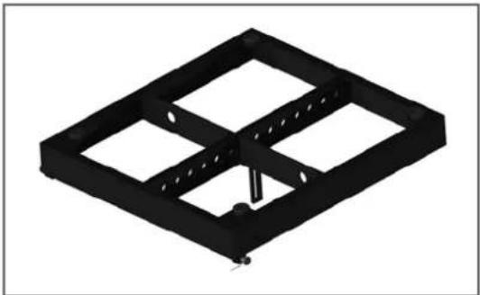
Fig. 6: CADISTM standard rigging frame 10
Fig. 7: CADISTM connector frame.... 10
Fig. 8: CADISTM wall mount, ceiling mount .... 10
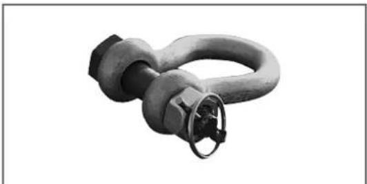
Fig. 9: Shackles for attaching motors, straps 10
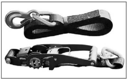
Fig. 10: Lashing strap for curving the array in compression mode .....11
Fig. 11: Quick-release pin ....11
Fig. 12: The CAD 208's set angle in compression mode 4.5° .....11
Fig. 13: Rigging frame at 0^ ......11
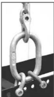
Fig. 14: Adjusting intermediate angles to curve the overall array .....12
Fig. 15: Mounting the standard rigging frame .....12
Fig. 16: Setting the angle to curve a CAD 208 array .....12
Fig. 17: Hoisting the top four CAD 208 enclosures .....12
Fig. 18: a, b, c: Rigging additional CAD 208 enclosures .....12/13
Fig. 19: Attaching the lashing strap ....13
Fig. 20: Example of a fixed mode application with a 4.5° angle .....13
Fig. 21: CAD 115 Sub rigging kit....14
Fig. 22: CAD 115 Sub pick points .....14
Fig. 23: Ground stack with the standard rigging frame .....14
Fig. 24: Ground stack with CAD 115 subwoofers .....14
Fig. 25: FirNet™ – Entering your PC's IP address ....17
Fig. 26: FirNet™ – Opening the Update Scene + Filter Settings dialog ....18
Fig. 27: FirNet™ – Selecting filters and controllers .....18
Fig. 28: FirNet™ – Opening the dialog box for loading individual filters ..18
Fig. 29: FirNet™ – Admin menu settings .....18
Fig. 30: FirNet™ – Front 19
Fig. 31: FirNet™ – Networked FIRNET and PC ......20
Fig. 32: FirNet™ – Networked hub and PC ....20
Fig. 33: FirNet™ – Rear .....21
Fig. 34: Required service tools....25
Fig. 35: CAD 208 with the grille removed....26
Fig. 36: CAD 208 with the side panels detached 26
Fig. 37: Dismantled CAD 208 baffle board with the woofer .....26
Fig. 38: Voice coil removed from the CAD 208 HF driver 26
Index of Tables:
Table 1: Weights of CADIS™ mid/high enclosures ....9
Table 2: Weights of CADISTM CAD 115 subwoofers ......9
Table 3: Set angle between the rigging frame and the first mid/high enclosure ....14
Table 4: Replacement parts list as of June 2009 ......25
Table 5: CADISTM FIRNET filter sets as of June 2009.... 27
A CADIS™ Speaker Cabinets
1 CAD 208 Mid/High Enclosure

natural_image
Black rectangular electronic device with perforated top panel and side connectors (no visible text or symbols)Fig. 1: CAD 208
Design and Construction
The CAD 208 mid/high enclosure's top and bottom panels are sloped at an angle of 7.5^ . The housing is made of polyamide resin reinforced with glass fibers, a tough, rugged, and weatherproof plastic exceptionally well-suited for constructing loudspeaker enclosures. When configured in a 0^ array, each cabinet may be tilted up to 15^ measured from the next higher rigging point, in 1.5^ steps. The baffle board covering consists of a metal grilled backed with two 8" speakers and the horns fed by the two 1" drivers.
The (passive) CAD 208 unit weighs 17.5 kg. It is 57.8 cm wide, 37.3 cm high and 27.2 cm deep (including rigging hardware).
Fully integrated rigging hardware serves to fly the mid/high units. It consists of four quick-release pins and three rigging connectors, two mounted on the sides and one on the back panel.
Electrical and Acoustical Data
The CAD 208 enclosure is loaded with two 8" cone chassis speakers and two 1" high frequency drivers feeding CD horns. An internal passive crossover addresses the drivers. The separating frequency for the HF drivers is 2,200 Hz.
The CAD 208 enclosure's nominal electrical power-handling capacity is 500 watts program (AES signal, 6 dB crest) at 16 ohms overall impedance. It produces a sound pressure level of 101 dB (1W@1m), measured under half-space conditions. Maximum SPL measured under the same conditions at a distance of one meter is 136 dB at 10% THD.
The enclosure radiates sound at a horizontal angle of 100^ and a vertical angle of 15%. Frequency response ranges from 100 Hz to 20 kHz ( ±3 dB).
Note: The bottom threshold frequency can drop to 70 Hz, depending on the height of the array.
The CAD 208 is thus able to serve as a fullrange speaker for pure speech reinforcement applications. We recommend using at least two enclosures for this.
Connections
The connector panel on the rear of the CAD 208 is recessed to protect the ports from harm. This enclosure may be equipped with three types of connectors:
a: Connector panel with two Speakon NL 4 ports (Input/Through)
Both ports' four pins are wired in parallel. Pin assignments are pin 1+ = mid/high +, 1- = mid/ high -, 2+ = sub +, 2- = sub 2-.
b: Connector panel with binding posts
for tri-amped (without internal crossover, with external controller) or passive (internal crossover network) and operating modes - optional
c: Connector panel with PG glands
with terminals inside; optional
1.1 Technical Data, CAD 208
(You'll find frequency measurements on page xxx.)
Nominal power handling (AES, 6 dB crest): 250 W RMS, 500 W program
Frequency range ± 3 dB:
75/100 Hz - 18 kHz (depending on controller)
SPL, 1W@1m:
95 dB full-space
101 dB half-space
SPL, max. SPL@1m:
130 dB@10%THD full-space*
136 dB@10%THD half-space*
Nominal impedance: 8 ohms
Woofers: 2x8" speakers
HF drivers: 2x1"
Horn: 100° horizontal, 15° vertical
X-over frequency: 2.2 KHz, 12 dB/ octave
Connector options:
2x Speakon NL 4
Barrier strip, optional
PG glands, optional
Housing: Polyamide resin
X-over: 2.5-way passive, pure crossover
Filter: Controller
Color: Black, white (or any RAL color on demand)
Front grille: Metal
Rigging hardware: Integrated, with three pick-points
Variable set angle for curving arrays:
0^, 1.5^, 3^, 4.5^, 6^, 7.5^, 9^, 10.5^, 12^, 13.5^ 15^
Weight:
17.5 kg / 38.6 lbs.
Dimensions (W x H x D):
57.8 cm × 23.8 cm × 37.3 cm
22-3/4 × 9-3/8 × 14-11/16"
Accessories:
• Rigging/ stacking frame for one to 24 CAD 208s
• Wall mount, ceiling mount
• Flight cases for four and eight CAD 208s each
* with four CAD 208s
2 Subwoofer CAD 115 Sub

natural_image
Black square speaker with textured grille and logo (no visible text or symbols)Fig. 2 Subwoofer CAD 115 Sub
Design and Construction of the Subwoofer
Made of 18-mm, 13-ply birch plywood, the CAD 115 Sub enclosure is coated with water-repellent, black acrylic enamel. The baffle board cover consists of a metal grille. The CAD 115 Sub weighs 38 kg. It is 58.3 cm wide, 57.3 high and 64 cm deep. Two slot grips have been routed into the side panels for easy transport and set-up.
Electrical and Acoustical Data
The CADIST™ 115 Sub enclosure is loaded with one 15" woofer. The CAD 115 Sub enclosure's nominal electrical power-handling capacity is 600 watts RMS at 8 ohms impedance. It produces a sound pressure level of 102 dB (1W@1m), measured under half-space conditions. Maximum SPL measured under the same conditions at a distance of one meter is 122 dB at 10% THD. The frequency response of the CAD 115 Sub ranges from 47Hz to 150 Hz (±3 dB).
Connections
The connector panel on the rear of the CAD 115 Sub enclosure is recessed to protect the ports from harm. On this enclosure, you'll find two Speakon NL4 connectors. Both ports' four pins are wired in parallel. Pin assignments are pin 1+ = mid/high +, 1- = mid/high -, 2+ = sub +, 2- = sub 2 .
2.1 Technical Data, CAD 115 Sub
(You'll find frequency measurements on page xxx.)
Nominal power handling (AES, 6 dB crest): 600 W
Frequency range ± 3dB: 47 Hz – 150 kHz (depending on controller)
Sensitivity, 1W@1m: 96 dB (50 Hz – 200 Hz) full-space 102 dB (50 Hz – 200 Hz) half-space
SPL @1m, max. SPL: 122 dB@ 10% THD full-space (60 Hz - 150 Hz) 128 dB@ 10% THD half-space (60 Hz - 150 Hz)
SPL, peak: 125 dB@ 10% THD full-space (70 Hz - 90 Hz) 131 dB@ 10% THD half-space (70 Hz - 900 Hz)
SPL @1m, max. calculated: 129 dB@ 10% THD full-space (2400 W peak) 135 dB@ 10% THD half-space (2400 W peak)
Nominal impedance: 8 ohms X-over frequency: External controller Speaker: 1x 15" neodymium woofer Connectors: 2x Speakon NL 4
Housing: 18-mm birch plywood
Color: Black, white (or any RAL color on demand)
Front grille: Metal
Rigging hardware: Four rigging rails integrated in the housing
Weight: 38 kg / 83.8 lbs.
Dimensions (W x H x D): 58.3 cm x 57.3 cm x 64 cm 22-15/16 x 22-9/16 x 2-1/2"
Optional accessories: - Rigging/ stacking frame - Connector frame (for up to ten CAD 208s under a CAD 115) - Set with 4 rigging adapters and quick-release pins for mounting up to two CAD 115 Subs and up to eight CAD 208s below the CADIS system rigging frame - Dolly with four 100-mm Blue Wheels
B CADIS™ Transport Solution
1 CAD 208 Cases
Two specially designed cases serve to transport four or eight CAD 208s each.

natural_image
Exterior view of a black industrial airbag with metal frame and wheels (no text or symbols visible)
natural_image
Exterior view of a dark metal-framed air duct box with attached mounting brackets and wheels (no text or symbols visible)Fig. 3a: CAD 208 cases
2 CAD 115 Sub Dolly
A dolly with four 100-mm Blue Wheels (optional) serves to transport CAD 115 Subs.

natural_image
Black rectangular electronic component with four metallic wheels and mounting brackets (no text or symbols visible)Fig. 3b: CAD 115 dolly
1.1 Dimensions and Weights of CAD 208 Cases
Case 4x CAD 208:
Width: 66 cm/26"
Depth: 46 cm/18-1/8"
Height (incl. casters): 121 cm/ 47-5/8"
Weight (empty): 42.5 kg/ 93.7 lbs.
Case 8x CAD 208:
Width: 85 cm/33-1/2"
Depth: 67 cm/26-3/8"
Height (incl. casters): 121 cm/ 47-5/8"
Weight (empty): 62.5 kg/ 137.8 lbs.
C Rigging the CADIS™ System
Please read these instructions carefully before you begin setting up the system!
1 Use
1.1 Intended Use
Specifications for intended use include the following:
When rigging enclosures, make sure the load is centered directly under the suspension point on the rigging frame. The rigging frame may be tilted (not to be confused with curved!) no more than 10% (6°). Note that the specifications for intended use require you to read and heed all of the operating instructions and comply with inspection and maintenance requirements.
Any use other than specified is misuse. The manufacturer shall not be liable for damages resulting from misuse.
1.2 Misuse
Improper use of rigging frames and incorrect handling of this load-carrying equipment can pose a serious danger. Never:
- use rigging frames to exert diagonal force or tension on loads
- use a crane to dislodge stuck or immovable loads
- lift people
- strike, knock or dent rigging frames
- heat-treat or weld rigging frames
- exceed the truss's maximum load-carrying capacity!
Note that in addition to the above specifications, the operational safety regulations of VBG 9 (accident prevention regulations of the German employers' liability insurance association) apply.
2 Warranty and Liability
HK AUDIO shall not be held responsible for damages due to improper use or failure to comply with the safety specifications for setup and operation.
All warranty and liability claims for personal injury and property damages are excluded if attributable to one or several of the following causes:
- failure to comply with operating manual instructions, voiding product liability and warranty claims
- unintended use and misuse of rigging frames
- failure to comply with operating manual instructions regarding transportation, storage, initial setup, operation, maintenance and repair of rigging frames
- unauthorized structural modifications performed on rigging frames
- unauthorized modification of the parameters specified in the operating manual
- inadequate or improper repairs
Important Notes on Safety!
Original CADIST™ rigging accessories have been certified as a complete and cohesive system by the safety standards authority TÜV. The rigging system's provisions for use require that it be installed in accordance with the following specifications. Before you begin installation, ensure that the rigging points (for example, a chain hoist) on the stage roof or the venue's ceiling comply with BGV-C1 accident prevention regulations and that the safety standards authority TÜV has certified them for the full load (see table 1). Prior to every installation, inspect all components to ensure they are in good operating condition, taking particular care to confirm that all quick-release pins and hardware connectors are undamaged.
The principle requirement for safe handling and trouble-free operation of rigging frames is a thorough understanding of fundamental operating safety and safety regulations.
This manual contains important instructions on how to safely use rigging frames.
2.1 Responsibilities of the Operator
As the operator, you are obligated to allow only those persons to work with rigging frames who are:
• 16 years of age or older,
- physically and mentally able, familiar with the basic rules of industrial safety and accident prevention, and trained in the handling of rigging frames.
Regularly review and confirm personnel's work safety awareness. In addition, task personnel with specific responsibilities for setting up, putting into service, operating, maintaining, and repairing equipment. Ensure that personnel are trained to work with the rigging frame only under the supervision of a proficient and experienced technician. Ensure also that defects, flaws and other damage that could impede safety are repaired immediately.
2.2 Storage, Maintenance, Inspection and Repair of CADIS™ Rigging Hardware
Storage and safekeeping when not in use
When not in use store the rigging frame in a safe place where it cannot be tipped over and is protected from exposure to the elements.
Inspections
§ 39, VBG ga of the German employers' liability insurance association's accident prevention regulations requires that load-carrying equipment be inspected by a qualified expert and possible defects be eliminated prior to initial commissioning by the recipient.
§ 40, VBG 9a requires that load-carrying equipment be inspected at least annually for cracks.
Additionally, equipment used in mobile applications where it is frequently set up and torn down must be inspected for cracks every six months.
Maintenance
You are authorized to replace easily serviceable wearing or standard parts in accordance with the manufacturer's instructions. Use original parts for this purpose.
Tighten screws and bolted connections whenever necessary.
Repair
In the event that parts of the load-carrying equipment have been deformed, it is up to the manufacturer to determine if they are repairable.
Solely the manufacturer is authorized to perform welding and repair jobs on load-carrying equipment.
2.3 Technical Specifications of CADIS™ Rigging Hardware
Load-carrying capacity of the rigging frame: 400 kg / 881.9 lbs.
Test load: 2,500 kg / 5,512 lbs.
Ambient temperature when in operation: min. -10^ C, max. +60^ C
2.4 Maximum Number of Flown CAD 208 Mid/High Enclosures
Caution: Flying more than 20 enclosures in a stacked array voids the safety standards authority TÜV's certification!
Refer to table 1 to determine flown loads. The sum of the weights of CADISTM enclosures plus the weight of the rigging frames equals the total load.
Note: Ensure that you add the weights of chain hoists, motors, cables and further stops to determine total weight!
| Quantity Weight [kg] [lbs.] | ||
| Passive: | ||
| 1 17.5 38.6 | ||
| 2 35 77.2 | ||
| 3 52.5 115.7 | ||
| 4 70 154.3 | ||
| 5 87.5 192.9 | ||
| 6 105 231.5 | ||
| 7 122.5 | 270.1 | |
| 8 140 | 308.6 | |
| 9 157.5 | 347.2 | |
| 10 | 175 | 385.8 |
| 11 | 192.5 424.4 | |
| 12 | 210 | 463 |
| 13 | 227.5 501.5 | |
| 14 | 245 | 540.1 |
| 15 | 262.5 578.7 | |
| 16 | 280 617.3 | |
| 17 | 297.5 655.9 | |
| 18 | 315 | 694.5 |
| 19 | 332.5 | 733 |
| 20 | 350 | 771.6 |
Table 1: Weights of CADIS™ mid/high enclosures
Weight of the standard rigging frame with shackles: 11.5 kg/25.35 lbs.
2.5 Maximum Number of Flown CADISTM CAD 115 Subs
When assembling CAD 115 Sub below the rigging frame, you have to turn the rigging frame round (pads appears to bottom)
| Quantity Weight [kg] [lbs.] | ||
| 1 38 | 83.8 | |
| 2 76 | 167.6 | |
| 3 114 | 251.3 | |
| 4 152 | 335.1 | |
| 5 190 | 418.9 | |
| 6 228 | 502.7 | |
Table 2: Weights of CAD 115 subwoofers
The combination of CAD 115 Sub and CAD 208 is based on the maximum authorised load for the rigging frame and connector frame.
• 1x CAD 115 Sub + 10 CAD 208
• 2x CAD 115 Sub + 8 CAD 208
Caution: Flying more than two subwoofers in stacked array with the connector frame voids the safety standards authority TÜV's certification!
CAD 115 subwoofers and CAD 208 mid/high enclosures may also be flown together on one rigging frame. Refer to table 2 to determine flown loads. The sum of the weights of CADISTM subwoofers and mid/high enclosures plus the weight of the rigging frames equals the total load.
Note: Ensure that you add the weights of chain hoists, motors, cables and further stops to determine total weight!
Weight of the standard rigging frame with shackles: 11.5 kg/25.35 lbs.
2.6 Pick-points for Flying CADIS ^™ Enclosures
Use only the rigging frame's shackles to attach motors, chain hoists and straps, inserting them into the holes in the center rod! Clear the area immediately below arrays of people before raising or lowering loads. Hoist and lower flown enclosures smoothly, avoiding abrupt stops or jerky motions. Secure the flown array with straps to prevent it from moving, for example, in the event of gusting winds.
2.7 Structural Modifications of CADIS™ Rigging Hardware
No structural modifications may be made without the manufacturer's consent. This also applies to welding work performed on load-bearing parts. Structural alterations require the manufacturer's written approval. Use original replacement and wearing parts only.
2.8 Original HK AUDIO Accessories
Use original HK AUDIO parts only (see chapter 3). The safety standards authority TÜV has not certified any other parts for use. Always install parts in accordance with these installation instructions. Compile and store all documents pertaining to the system in a safe place.
2.9 Initiation and Operation
§ 39, VBG 9a of the German employers' liability insurance association's accident prevention regulations requires that load-carrying equipment be inspected by a qualified expert and possible defects be eliminated prior to initial commissioning by the recipient.
§ 41 VBG 9a requires that load-carrying equipment be subjected to a non-routine inspection following damage, repair work and other incidents that can affect load-carrying capacity.
3 Flown Applications and Components of CADIS™ Rigging Hardware

natural_image
Black industrial container or structure with multiple tiers and mounting holes, mounted on a metal frame (no visible text or symbols)Fig. 4: 8 flown CAD 208 mid/high enclosures
CADISTM rigging hardware consists of the following parts:
- a standard rigging frame with two shackles for attaching motors, lashing straps or chain hoists. The rigging frame also serves as the base for ground stacks.
- an optional two-part lashing strap for curving the array in compression mode
- integrated rigging hardware on the side and back for flying CADIST™ enclosures
- four quick-release pins per CAD 208 for connecting the enclosure to another enclosure or the rigging frame (eight 17-mm QRP)
- connectors for mounting the CAD 115 Sub to the rigging frame
- rigging yoke for mounting the CAD 208 below the CAD 115 Sub
Important note on pins: Quick-release pins serve to connect rigging hardware and speaker enclosures, and their proper function must be tested and verified. The pins must always engage fully in the (fitted) hole. Under no circumstances may these pins release on their own when subjected to tractional forces. The nib in the center of the pinhead must always be depressed to insert pins; it releases the ball detents in front. Once the pin engages in the hole, the nib must glide back to its initial position.

natural_image
Two stacked black electronic equipment units with visible ports and cables, no text or symbols present.Fig. 5: CAD 208 mid/high enclosure with integrated rigging hardware
natural_image
3D rendering of a black rectangular electronic component with four square cutouts and a central mounting bracket (no text or symbols)Fig. 6: CADISTM standard rigging frame

natural_image
Black metal frame with mounting brackets and a central vertical support (no text or symbols)Fig. 7: CADISTM connector frame

natural_image
Two black metal structural components with mounting flanges and a circular component on the right (no text or symbols visible)Fig. 8: CADIS ceiling mount / CADIS wall mount
natural_image
Close-up of a metallic pipe fitting with a coiled spring (no text or symbols visible)Fig. 9: Shackles for attaching motors, straps
natural_image
Two black-and-white images of cable harnesses with hooks and straps, no text or symbols visible.Fig. 10: Lashing strap for curving the array in compression mode

natural_image
Close-up of a black cylindrical mechanical component with a flanged end (no text or symbols visible)Fig. 11: Quick-release pin
4 Adjusting the Set Angle between Two CAD 208 Mid/High Enclosures
You have two options for adjusting the set angle between CAD 208 enclosures - compression mode and fixed mode. In compression mode, the angle is easily adjusted after the flown array is up and in place. This requires a lashing-strap or chain hoist. In fixed mode, the angle is determined during setup and the flown array cannot be adjusted later. This option does not require a lashing-strap or chain hoist.
4.1 Compression Mode
Determine the set angle between two enclosures simply by adjusting the lower Set Angle pin; the top pin always glides in the slot on the Link connector. This way one person can easily curve the array.
The following angles may be adjusted between two CAD 208 enclosures: 0^ , 1.5^ , 3^ , 4.5^ , 6^ , 7.5^ , 9^ , 10.5^ , 12^ , 13.5^ , and 15^ .

Fig. 12: The CAD 208's set angle in compression mode is 4.5°
The rigging hardware is designed so that you can adjust the set angle on a flown CADISTM array; that is, after it has been hoisted.
How does this work?
The pin that determines the set angle is merely a predefined stop for the flexible connector component when the entire CADISTM array is compressed accordion-style at the back and adjusted using a lashing strap or chain hoist. When no force is exerted, the entire mid/high array is suspended at 0°, meaning that the Set Angle pin is easily repositioned. kann verstellt werden.
Important note: The pin labeled Link connects individual CAD 208 cabinets. Ensure this pin is inserted; otherwise the enclosures will not be connected to each other and may swing forward!
4.1.1 Preparations
The following section describes how to set up an array in compression mode. Use CADIST™ CAPS software to select rigging frame pick points for setting the angles between CADIST™ 208 mid/high enclosures.
4.1.2 Mounting the Rigging Frame
It takes two people to perform these tasks. Remove the quick-release pins from the rigging frame and the two pins on the back of the top CAD 208 enclosure. Place the rigging frame on the enclosure. First attach the two front connectors. Turn the rigging frame's connector component down and slide it into the rear rigging connector.
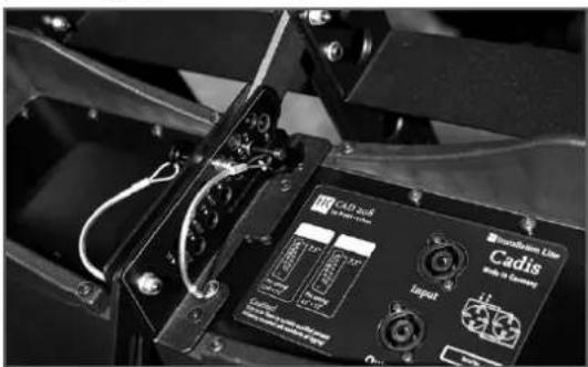
You may mount the top mid/high enclosure to the rigging frame in fixed or in compression mode. To attach it in compression mode, insert the first pin through the hole labeled Link on the enclosure and attach the connector component by inserting the second pin through the slot into the hole labeled 7.5°. To attach it in fixed mode, insert the first pin through the hole labeled 4.5° on the enclosure and attach the connector component by inserting the second pin through the slot into the hole labeled 7.5°.
Note: The maximum set angle for the top mid/high enclosure is 7.5^ (with the rigging frame set to 0^ ).
natural_image
Close-up of a mechanical device with labeled components including CAD/Tool, Input, and Transform Line (no readable text or symbols beyond labels)Fig. 13: Rigging frame set to o°
Attach to the top rigging frame the shackle that will hold the motor's hook. Your choice of pick point depends on how sharply you aim to curve the entire array later.
Note: Depending on application, you may not be able to select a pick point with a shackle. In this case, use two shackles and a suitable O ring as shown in Figure 14.
natural_image
Close-up of a metallic chain link with hanging weights (no text or symbols visible)Fig. 14: Adjusting intermediate angles to curve the overall array
Check all pins on the top rigging frame to ensure they are firmly seated and attach the motor to the shackle.
Important: Ensure the motor's chain bag hangs freely and does not rest on the rigging frame!

natural_image
Close-up of a mechanical device with a long rod inserted into a black box, no visible text or symbols.Fig. 15: Mounting the standard rigging frame
Engage the motor to lift the cabinet from the case. Roll the case off to the side. Remove the two front pins from the lowest enclosure and fold down its connector component. Now you can rig the second two-cabinet block.
Curve the four CAD 208 enclosures as desired for the given application by setting the pins on the back accordingly. Determine the desired angle using the pin labeled "Set Angle".

natural_image
Black-and-white photo of four stacked electronic devices with visible circuitry and control panels (no readable text or symbols)Fig. 16: Setting the angle to curve a CAD 208 array
Connect the speaker cords to the four enclosures that will later be at the top of the array. Bear in mind that you must attach one of the shackles on the rigging frame to the lashing strap or chain hoist that will later serve to pull back the ends of the array and curve out its front face. Do this now.
Tip: If you intend to rig more CAD 208 enclosures, we recommend that you attach all the required speaker cords to the top rigging frame now because this task gets more difficult as the array grows. Be sure to use cords of sufficient length!
4.1.3 Rigging Additional CAD 208 Enclosures
Hoist the mounted mid/high enclosures to a height that allows you to roll additional CAD 208 cabs under the array. Remove the two front pins from the lowest flown enclosure.

natural_image
Large black industrial equipment with vertical supports and a suspended load, no visible text or symbolsFig. 17: Hoisting the top four CAD 208 enclosures
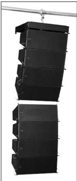
Move the additional CAD 208 enclosures into position. Slowly lower the top four cabinets until the two front connectors engage. Insert the two front pins first, ensuring that they engage fully and securely. You may have to shift the two enclosures slightly to ease the pins into position. In order to attach the rear connector component, you must swivel it out of the rail so that it faces down. To connect the two blocks, insert the pin through the connector's slot and through the hole labeled "Link".
natural_image
Two black industrial storage tanks suspended in a metal rack, no visible text or symbolsFig. 18a: Mounting additional CAD 208 cabs: Mounting block a

natural_image
Black-and-white photo of two stacked electronic equipment units with visible ports and wiring, no readable text or symbols.Fig. 18b: Mounting additional CAD 208 cabs: Setting the CAD 208's angle

natural_image
Black industrial structure with multiple vertical panels and a horizontal pipe, no visible text or symbolsFig. 18c: Mounting additional CAD 208 cabs: Mounting block b
Hoist the CADISTM array with the eight enclosures high enough so you can add further cabs to the bottom of the array.
Insert the pins on the back of the bottom four enclosures' "Set Angle" holes to achieve the desired curvature. Connect the remaining speaker cords.
Repeat the above procedure if you wish to add more CAD 208 enclosures to the flown stacked array.
4.1.4 Hoisting the System
The enclosures are rigged, speaker cords are all connected, and the pins are set in the required configuration.
If you have opted for compression mode and want to use the lashing strap to curve the CADIST™ array, connect one of its hooks to the rigging frame. Using a shackle (with an 8-mm bolt), attach the hook on the other end to the bottom cab, with the best choice of anchor being the connector component.
Tighten the strap until it exerts enough force to curve the array as desired.

natural_image
Curved black staircase with horizontal panels, no visible text or symbolsFig. 19: Attaching the lashing strap
Once you have hoisted the CADISTM array, secure it against gusts of wind or unintended twisting using two lashing straps or ropes.
4.2 Fixed Mode
To determine the set angle between two enclosures in fixed mode, you must insert one pin (Set Angle) and secure the connector in place with the second pin. To set the selected angle, insert the pin into the neighboring hole labeled "Link" above the selected angle (Set Angle). This fixes the connector component in place so that it is immobile in all directions.
This gives you the same set angles between two CAD 208 enclosures to choose from as in compression mode; that is, 0^ to 15^ in 1.5^ steps.

Fig. 20: Example of a fixed mode application with a 4.5° angle
Follow the same procedure as for compression mode to set up the system in fixed mode. Often when arrays are sharply curved it becomes difficult to rig additional blocks. In this event, you must mount enclosures individually from below.
5 Flying CAD 115 Subwoofers
5.1 Components
You'll need the following components to fly CAD 115 subwoofers:
- a standard rigging frame
• the pick points on the side panels of CAD 115 subwoofers - CAD 115 subwoofer rigging kit consisting of four connector components and eight pins
- rigging yokes for mounting CAD 208 enclosures to CAD 115 subwoofers (2 parts + 6 pins)

natural_image
Black mechanical device with two circular components connected by a coiled cable (no text or symbols visible)Fig. 21: CAD 115 Sub rigging kit

natural_image
Close-up of a white curved metal bracket with black connectors and a small circular component attached (no text or symbols visible)Fig. 22: CAD 115 Sub pick points
5.2 As an Independent Bass Array on a Second RiggingFrame
The standard rigging frame is certified to fly up to ten CAD 115 subwoofers in stacked array. Be sure to also read and heed the safety regulations in chapter C of the manual.
Rigging
Set the standard rigging frame on the CAD 115 subwoofer with the rubber feet facing down. Remove the four pins on the rigging frame. Attach the four (optional) connector components between the rigging frame and the CAD 115 enclosure using the pins. Attach the shackles for the motor to the rigging frame. Attach the motor to the shackle and lift the subwoofer. Now you can rig additional CAD 115 bins below this subwoofer. You need four connector components and eight pins for each subwoofer to do this.
5.3 In Combination with CAD 208 Mid/High Enclosures
Configuring subwoofers and mid/high enclosures together in a single array may be practical, depending on application. Subwoofers must be rigged on top of the flown array for this application.
Mind the rigging frame's maximum permissible load. Before you begin, add up the individual components' weights to determine the total system weight. Refer to tables 1 and 2 in chapter C, Rigging the CADIST™ System, for weight specifications.
Use the connector to attach the top CAD 115 Sub to the rigging frame. To add mid-/high-range enclosures to the array, mount the optional rigging yoke to the bottom subwoofer by inserting four pins into the enclosure's recessed rigging rails.
You may mount the first mid/high enclosure to the rigging yoke in fixed or in compression mode. For a o° set angle, insert the first pin through the slot labeled Link on the enclosure and attach the connector component by inserting the second pin in the hole labeled o° Ground-stacking.
This configuration is recommended for smaller venues, for example, in which enclosures cannot be flown, or when you want to aim the array to cover galleries, terraces or balconies.
5.4 With a Standard Rigging Frame
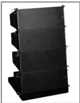
Set the standard rigging frame, without shackles and with the rubber feet facing down, on the ground, on bass bins (attaching the frame to the bin) or on the stage so that the connector components for the CAD 208 enclosures face up.
natural_image
Stacked black industrial equipment unit with three vertical panels and mounting brackets (no visible text or symbols)Fig. 23: Ground stack with the standard rigging frame
Remove all pins from the rigging frame and mount the CAD 208 enclosures upside down, one after another. The procedure is the same as for a flown system in fixed mode, except that enclosures are stacked upside down. This lets you tilt the stack downwards by up to 7.5°. To do this, use the set angles in fixed mode. The table below shows which angle between the rigging frame and the first mid/high enclosure gives you the desired down-tilt:
| Desired down-tilt Label on the CAD 208 | |
| 0^ (horizontal) 7.5^ | |
| 1.5^ 6^ | |
| 3^ 4.5^ | |
| 4.5^ 3^ | |
| 6^ 1.5^ | |
| 7.5^ 0^ | |
Table 3: Set angle between the rigging frame and the first mid/high enclosure
Caution: Always secure ground stacks with a suitable lashing strap to prevent slippage!
5.5 With CAD 115 Subwoofers
natural_image
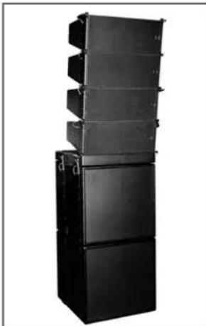
Stacked black industrial equipment units on a white background (no text or symbols visible)Fig. 24: Ground stack with CAD 115 subwoofers
Operating the System
We recommend that you follow the procedure described to help prevent errors and quickly troubleshoot problems. The adverse effect of a mid/high cabinet dropping out or an incorrect connection can seriously degrade any system's performance, especially that of a line array!
5.6 Connecting Speaker Cords
Always lay out cables clearly and orderly. You should be able to readily identify which enclosure connects to which power amp channel at any time. This ensures flaws such as defective cords can be pinpointed and redressed quickly.
5.7 Checking Individual Mid/High Enclosures
The best method of checking cabinets is to play a familiar track on a CD (for example, the latest HK Audio demo CD), routing the signal into the mixer and out via the master channel. Set the master level to a low to medium setting.
Turn up the given channel's gain knob. You will hear the signal rendered by the two connected mid/high cabinets and the assigned controller should indicate the incoming signal level.
Important note: If you are located outside the high frequency signal's directivity coverage, you will not be able to hear this signal! This system check is best performed with a helper positioned a suitable distance from the array. If you see the bottom of the mid/high unit as a flat surface, you are definitely outside its directivity coverage.
Turn the power amp channel's gain knob back down after hearing the signal. Follow the same procedure for all other power amp channels that you wish to use. Be sure to turn the gain knob down after each successful test.
Note: This procedure checks mid/high cabinets in descending order; that is, from top to bottom. A cabinet's height affects its directivity, so the lower the enclosures, the closer the listener should move in towards the array.
Follow the same procedure to check subwoofers.
Once you have checked all cabinets successfully, turn up all gain knobs, one after the other.
Start with the channel 1 gain knob for the top mid/high units, and then turn up the channel 2 gain knob, and so forth. With every additional channel that you activate, you should hear a boost in low midrange response. If not, this may be due to a phase inversion in the NF (or in extreme cases, in the speaker cords). Proceed in the same manner for the subwoofer channels.
5.8 Configuring the Controller Network Using Audio Controller Software
Once you have performed these tests, you can configure the controller network. The type and size of the configuration of course depends on the given sound reinforcement task (PA left/right, center, out-fills, etc.).
Read the chapter on controller software in the manual to learn more about networking controllers, creating groups, and setting delays and levels.
6 Tearing Down and Transporting the System
To tear down the system, start where you left off and work your way backward; that is, proceed in the reverse order of assembly.
These tips should make the job of tearing down the mid/high array easier if you use cases for your CADISTM system:
Lower the array until the bottom of the case for mid/high units fits under it.
Engage the motor or chain hoist to relax the tension on the strap that is curving the array. Caution: The array may swing out towards the front! Disconnect at least the four lower cabinets' cords.
Set the Set Angle pins that are determining the array's curving to 0^ ! This ensures the array will not buckle when lowering and setting it on the bottom of the case. This also makes it easier to dismantle the four-cabinet block.
Always insert the front pins into the holes on the rigging connector to ensure they are not damaged or torn off when the array is lowered into the case! Carefully lower the array into the case. First remove the rear Link pin connecting the two mid/high units. Then remove the two front pins. Raise the array slightly so that the lower four-cabinet block can be rolled away.
D CADIS™ Aiming Software Setups with EASE Focus
1 Acoustic Simulation of CADIS™ Setups with EASE Focus and the CADIS-GLL for EASE
An acoustic simulation serves to predict expected audio results. Its ability to predict how well a proposed sound reinforcement solution will work in practice makes it very helpful in mastering sound reinforcement challenges. Best of all, it lets you perfect the sound system before you actually set it up. The simulation helps detect errors beforehand, sparing you the considerable extra effort it takes to correct flaws after the system is up. For this reason, acoustic simulations have become standard practice for fixed installations and a handy tool used in many projects.
With the arrival of line arrays, acoustic simulations are seeing more frequent use for mobile sound reinforcement. And for good reason, because achieving a satisfying audio result with a line array requires very careful configuration and alignment. To help you determine such a best-case configuration and alignment of the CADIST™ Line Array before you set up or install it, HK AUDIO offers a system definition file (CADIS.EFO) for the simulation program EASE Focus and a generic speaker library file (CADIS.GLL) for EASE version 4.2 and higher.
EASE 4.2 takes into account the given acoustical conditions to calculate all relevant audio parameters such as direct and overall sound levels, delay times, clarity, speech intelligibility, and so forth, as well as to create auralizations. EASE 4.2 is used above all to plan CADISTM system configurations for fixed installations and larger mobile sound reinforcement projects.
In contrast, EASE Focus is employed for mobile sound reinforcement applications that allow little time for complex simulations. It calculates a CADIST™ configuration's sound dispersion across audience areas in a vertical sectional view, whereby the room's acoustical influences are not taken into account. EASE Focus lets you determine the best configuration and alignment for a sound rein-
forcement application in a virtual simulation; that is, without having to map the room's complexities and without setting up, testing, and adjusting the system until you find the optimum solution.
Note: Bear in mind that precisely measuring a room's dimensions and geometry (particularly of the audience areas) and carefully planning the CADISTM configuration will always take less time than determining the best possible configuration by trial and error. Oftentimes, CAD files - or at least scale diagrams of halls – are available on venues' websites. These sources can provide all the information required for prior simulation.
The following applies to every simulation:
Calculated SPL values can only be reproduced precisely using the appropriate test signals. In (live) music applications, differences may occur as a result of different spectra and crest factors.
To learn more about how to simulate sound reinforcement scenarios and handle EASE Focus and EASE 4.2 simulation programs, functions, and parameters, see the given program's manual or online help (http://www.easefocus.de/downloads.html). You'll find a description of functions and options of the generic loudspeaker library file (CADIS.GLL) embedded in EASE 4.2. Open this description by clicking the Embedded Files button in CADIS.GLL. To access it in the EASE GLL Viewer, open CADIS.GLL, go to the File menu, and select the option Embedded Data Files.
E Controlling CADIS ^TM
You have two options for controlling a CADISTM system:
- In two-way active mode, the FIRNET serves as a stereo FIR controller.
- In tri-amped mode, the amps drive the CAD 208 speakers directly, without internal X-overs.
You have a choice of two amps for powering the system, and the appropriate filter settings are available for each:
- FIRNET Linear Phase Controller / VX2400 power amp (abbreviated VX in the following)
- FIRNET Linear Phase Controller / LAB.gruppen FP 10000Q (abbreviated FP in the following)
Note: When operating your system, always ensure components are connected properly and the correct gain settings are dialed in at the controller and on the power amps. For more on this, see section F, Controllers and Controller Software.
F Controllers and Controller Software

1 FirNet™ Controller
Note: This quick guide provides fast orientation if you have experience using devices similar in design. A detailed user manual is available for downloading at www.hkaudio.com.
Getting started
1. Fundamentals
The controller requires different settings for systems driven by different power amps, so you must adjust the Max Output Level in the Admin menu according to which amps you're using, HK AUDIO VX 2400 or Lab.Gruppen FP10000Q. What's more, different system configurations need different speaker filters. The controller ships without speaker filters, so you'll have to load the entire filter library or the individual filter that you need. You'll find the filters alongside LI-PAN software and other important info on the included CD-Rom.
Here's what you must do before you run the FIRNET controller for the first time:
- Us a network cable to connect the network ports of your PC and the FIRNET controller.
- Store the files on the CD-Rom in a new folder on your PC.
- Install LIPAN software so you can load filters and edit the FIRNET on your PC.
- Load speaker filters. You'll also find filter banks and individual filters serving to operate the FIRNET with Lab.Gruppen FP10000Q and HK AUDIO VX 2400 power amps on the included CD-Rom.
- Check the analog gain structures in the FIRNET controller's Admin menu items "Max Input Level" and "Max Output Level". Adjust the settings if necessary – that is, if you're using the FIRNET with Lab.Gruppen amps.
2. PC settings
Entering an IP address to the PC:
The connected PC must have an IP address with the first seven numerals 192.168.1.100 (-254). In other words, ensure the bold numbers appear in the first three address blocks. Feel free to use any number from 100 to 254 in the last address block. However, the PC and connected controller may not have the same numerals in the last block.
Viewing the controller's IP address:
Network environment → double-click network link → Scroll down to and right-click TCPIP:
→IP address properties (If you change the IP address, you must restart the PC.) This is where you can view your controller's preset IP address after the FIRNET boots: Navigation wheel → Scroll down one in the menu to view the IP address. You can only change it on the FIRNET controller. Read the detailed explanation in the Quick Guide or FIRNET manual to learn more about this.
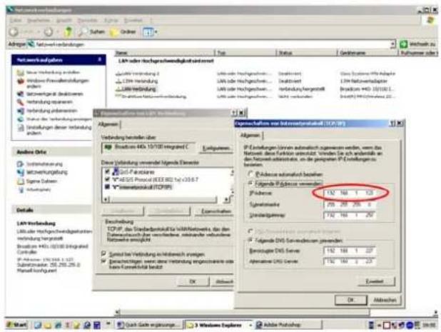
Fig. 25: FirNet™ Entering your PC's IP address
3. Installing LIPAN software
Use a Cat 5 cable (RJ 45) to connect your PC's network port to the X port on the rear of the FIRNET. If you want to run several FIRNET controllers simultaneously, connect the first controller's II port to the next controller's X port.
Place the CD-Rom in your disk drive and store all data in a newly created folder. Then select the file named XP_Install HK AUDIO LIPAN Ver 1.2.0.4.zip, or VISTA_Install HK AUDIO LIPAN Ver 1.2.0.4.zip if your PC runs WIN Vista.
Unzip the .zip file on your disk drive into the same folder. Double-click XP_Install HK AUDIO LIPAN Ver 1.2.0.4.exe to start the LIPAN software's installation routine.
Once you have installed the LIPAN application (for WIN XP or WIN Vista) on your PC, load to your controller(s) the filter banks or individual filters you need to run your system. The installation routine placed a blue LIPAN button on your desktop; double-click it.
4. Loading filter banks
4.1 Loading an entire filter bank
Open the filter dialog via Controller/Update Scenes + Filter Libraries. Select the filters you wish to load from the folder (Open Libraries), and then the target controllers (click Select All or checkmark them -individually). Click the Send button to start loading.

Fig. 26: FirNet™ - Opening the Update Scene + Filter Settings dialog
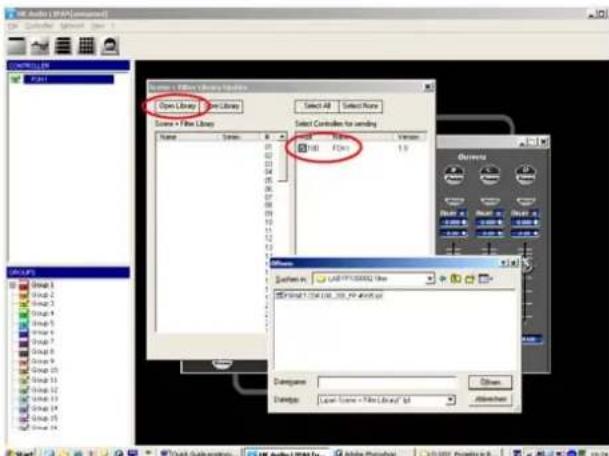
Fig. 27: FirNet™ - Selecting filters and controllers
4.2 Loading a single filter
Open the Controller/Save Filter to Controller dialog and select the filter from the file in the newly created folder.
Heads up: Always wait until the devices finish loading filters. A message will appear on your desktop.
![Audio LPAE [Comma] File Edit View Insert Show Format Help Update Format Update Screen + Filter Library Composition Name: Linear 1.0000 Language Group 1 Group 2 Group 3 Group 4 Group 5 Group 6 Group 7 Group 8 Group 9 Group 10 Group 11 Group 12 Group 13 Group 14 Group 15 Group 16 Group 17 Group 18 Group 19 Group 20 Group 21 Group 22 Group 23 Group 24 Group 25 Group 26 Group 27 Group 28 Group 29 Group 30 Group 31 Group 32 Group 33 Group 34 Group 35 Group 36 Group 37 Group 38 Group 39 Group 40 Group 41 Group 42 Group 43 Group 44 Group 45 Group 46 Group 47 Group 48 Group 49 Group 50 Group 51 Group 52 Group 53 Group 54 Group 55 Group 56 Group 57 Group 58 Group 59 Group 60 Group 61 Group 62 Group 63 Group 64 Group 65 Group 66 Group 67 Group 68 Group 69 Group 70 Group 71 Group 72 Group 73 Group 74 Group 75 Group 76 Group 77 Group 78 Group 79 Group 80 Group 81 Group 82 Group 83 Group 84 Group 85 Group 86 Group 87 Group 88 Group 89 Group 90 Group 91 Group 92 Group 93 Group 94 Group 95 Group 96 Group 97 Group 98 Group 99 Group 100](/content/2026/05/911917/images/4d2682243b4d4b17587b6ee2bfc10eebb1541400bf8e30435382fa3a4c87eedd.jpg)
Fig. 28: FirNet™ - Opening the dialog box for loading individual filters
Then go to the Admin window and enter the correct values for Max Output level (+6 dB for HK AUDIO VX 2400 amps, +18 dB for Lab.Gruppen FP 10000Q amps).
![HC Audio LPAI [Control] File Edit View Insert CONTROLLER FPGA Continuous Wave (1000 / 1000) Signal Quinture Control Rate Output Rate IF Amplitude Continuous Wave Continuous Wave Max. Distortion Line Max. Amplitude Continuous Wave Max. Distortion Line Max. Amplitude Continuous Wave Max. Distortion Line Max. Amplitude Continuous Wave Max. Distortion Line Max. Amplitude Continuous Wave Max. Distortion Line Max. Amplitude Continuous Wave Max. Distortion Line Max. Amplitude Continuous Wave Max. Distortion Line Max. Amplitude Continuous Wave Max. Distortion Line Max. Amplitude Conventional Wave Output Quinture Continuous Wave Output Max. Distortion Line Max. Amplitude Continuous Wave Max. Distortion Line Max. Amplitude Continuous Wave Max. Distortion Line Max. Amplitude](/content/2026/05/911917/images/e939a9c5786129b9832bdd7ab16b2f4df5226af87aefc4955fbf47eb621f62cd.jpg)
Fig. 29: FirNet™ - Admin menu settings
For more info, read the LIPAN software's and FIRNET controller's operating manuals, which are also on the included CD-Rom.
You'll find all the latest files for downloading on our website at www.hkaudio.com.
FirNet Display
The LCD shows information on presets and parameters. The default readout appears after the device is powered up, and then the display indicates current speaker selection settings and the LAN status. Once you begin navigating adjustable parameters, it shows values pertaining to these parameters.
FirNet Menu Keys
Menu keys (Speaker, Level, Scene, Delay/Phase und Admin) serve to access the various parameter sections. You can adjust the indicated parameters and save these settings using the edit select keys (cursors and back key) for the selected input and output. Pressing the back key always takes you to the next higher menu level.
Note: The device retains stored values even if a power failure occurs or it is unplugged from the mains supply.
FirNet Channel Mute
• Using Channel Mute Shortcuts to Mute Outputs A/B/C/D
You can use combinations of the Admin menu key and the four other menu keys (Speaker, Scene, Level, Delay/Phase) to mute the FIRNET's output channels in A/B/C/D sequence. For example, if you wish to mute output A, press Admin + Speaker; to mute output D, press Admin + Delay/Phase. Press the same combination again to reactivate the output.
Note: Each of the output channels' red signal LEDs show the given output's mute status (constant red = MUTE).

Fig. 30: FirNet™ - Front
Control features Front
1 SPEAKER Key
- Selects a speaker-specific filter set from the FIRNET speaker series database
2 SCENE Key
- Loads scenes setups from the FIRNET database and stores them to the database
3 LEVEL Key
- Adjusts input and output levels in the range of -40 dB to 12 dB
- Increment = 0.1 dB in the range of 12 dB to -12 dB
• Increment = 0.5 dB below -12 dB
4 DELAY/PHASE Key
- Adjusts delay time up to 500 ms for the FIRNET controller's inputs
- Adjusts delay time up to 25 ms for the FIRNET controller's outputs
- Inverts the phase position of the audio signal routed to the FIRNET controller's inputs and outputs
5 ADMIN Key
- Locks keys to prevent unauthorized or unintentional handling
- Selects the audio signal input and associated options
- Adjusts peak analog input and output levels to match FIRNET to upstream or downstream audio devices
- Edits the IP address, controller name, and display contrast
- Serves to select the delay unit of measure (ms, m, ft, samples) and enter the surrounding temperature to calculate the speed of sound
6 AES IN LED Display
- Lights up blue when the FIRNET controller's digital AES/EBU IN signal input is selected
- Extinguished when the FIRNET's analog signal inputs are selected
EXT SYNC LED Display
- This LED lights up blue when an external AES/EBU signal is enabled for the FIRNET's synchronization option and the device receives an incoming signal.
- Extinguished when the controller's internal synchronization is selected
8 INPUT LED Displays (10 LEDs, green/yellow/red)
- Green segment: Audio input level in the range of -48 to -12 dB at full scale
- Yellow segment: Audio input level in the range of -12 to 0 dB at full scale
- Red segment: Audio input level is overdriving the AD converter
Note: An overdriven AD converter generates -distortion that the FIRNET's limiter cannot suppress. If the red LED lights up, set the FIRNET's input gain to a higher value (see the section Setting Peak AD Level in the -Adjusting Parameters chapter) or reduce the source audio device's -output level! Be sure to heed the gain level recommendations for -connected amps, particularly when operating an FP10000Q power amp.
9 LCD
- 2 x 24 characters
• Shows in normal operating mode the controller name, the selected filter, and the existence of a network link
• Shows options and editable parameters when you access a menu
10 OUTPUT LED Displays (10 LEDs, green/yellow/red)
- Green segment: Audio input level in the range of -48 to -12 dB below the limitervalue
- Yellow segment: Audio input level in the range of -12 to 0 dB at below the limiter value
- Red segment: Limiter is attenuating the audio input level. The given output is muted (LED lights up continuously)
11 Back Key
- Returns to the next higher menu level
- Exits edit windows without assigning adjusted values
12 Navigation Keys
- Navigates to the next or previous menu option
- Selects and changes parameters in the edit windows
- Top key: Arrow up while scrolling in the menus
- Bottom key: Arrow down while scrolling in the menus
• Right key to the right to adjust (lower numerical values) - Left key to adjust parameter values (lower numerical values)
- Enter key to confirm the adjusted value
13 Reset Button
The FIRNET controller reboots after 10 seconds, and then loads the most recent settings. Unsaved settings are not retained.
14 Soft Reset and Hard Reset key combinations
The FIRNET offers two more reset functions:
Soft Reset: (Admin+Back+Enter for 3 seconds)
Loading the default preset "Szene O" Functions:
- No speaker/ no filter selected
- No signal routed to the exits
- All FIR initial coefficients set to o
- No filters set; filter must be reloaded!
- X-Over set to bypass
- Input/ output gain set to o
- Delay parameter set to o
• IIR EQs all input gains set to o,
• All limiters set to +10dB threshold - Admin parameters remain unchanged
- Outputs 1-4 muted
• IIR EQs output set to bypass (LIPAN Off) and gain to o
Hard Reset: Factory default
(Speaker+Admin+Back for 3 seconds)
Functions:
- Filter banks deleted
- Input assign A/B
- Analog input source
• Sample rate 96 kHz
• Dig Clk Sync: internal
- Admin: Keylock deactivated
- Delay unit: ms
• Temperature: 20°C
• Display contrast: 15
• Device name o
• Max input: +18 dBu
• Max. output + 6 dBu (setting for VX 2400)
- IP not reset
Rear Panel Connectors
14 100-240 V\~ / 50-60 Hz Mains
This three-pole non-heating equipment connector with a ground contact connects the FIRNET controller to the mains power supply. The multi-voltage power supply unit allows the controller to be connected directly to all mains voltages ranging between 100 V and 240 V without requiring transformers and the like. Its maximum power consumption is 40 VA, which corresponds to about 175 mA maximum current consumption at 230 V mains voltage and about 400 mA at 100 V. Do not connect the device using anything other than a three-pole connector with a ground contact. The mains outlet must also be equipped with a ground contact. Never use damaged cords, plugs, or sockets.
15 GPIO
This 25-pin sub-D port provides four each floating inputs and outputs for future firmware versions' use, for example, to remote-control power amps or switch controlled devices. Current firmware does not support this feature.
16 Ethernet PC Control Ports
Ethernet ports relay remote control and monitoring data between a PC and FIRNET controllers via computer networking hardware. The Ethernet X and Ethernet II connectors are RJ-45 ports (Input X = for cross input, II = parallel input).
Cabling:
If you do not wish to use further network hardware such as hubs and switches, connect the PC's network port to the first FIRNET's Ethernet X port using CAT5 network cable. Then also use a CAT5 network cable to connect the first FIRNET's Ethernet II port to the second controller's Ethernet X port, and so forth.
Use a CAT5 network cable to connect the FIRNET controller to hubs or switches, patching the FIRNET controller's Ethernet II port to the hub or switch's network port. To daisy-chain further FIRNET controllers, connect the first FIRNET's Ethernet X port to the second controller's Ethernet II port, and so forth.
Tip: We recommend that you connect all FIRNET controllers to switches. If you do not, and one controller fails in setups comprising several -connected FIRNET controllers, the entire networked chain will drop out.
Fig. 31: FirNet™ - Networked FIRNET and PC
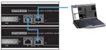
Fig. 32: FirNet™ - Networked hub and PC

17 AES/EBU IN Digital Audio Input
Connect signal sources with digital outputs to these three-pin female XLR sockets. Pin assignments are pin 1 = ground, pin 2 = signal, and pin 3 = signal. The FIRNET controller accepts sampling rates of 48 kHz and 96 kHz, which may be selected via a menu option.
Input-Output Signal Routing:
The analog INPUT A – that is, the left channel of the digital AES/EBU signal - delivers the signal to OUTPUT A and OUTPUT B. OUTPUT C and OUTPUT D receive their signal from analog INPUT B, that is, the right channel of the digital AES/EBU signal. You can reroute signals in the LIPAN software's Admin window.
18 AES/EBU OUT Digital Audio Output
The signal patched into the AES/EBU input can be routed through in digital format to other devices via this three-pin male XLR port. Pin assignments are pin 1 = ground, pins 2 and 3 = signal. The FIRNET amplifi es the incoming digital audio signal to preserve signal quality. If a FIRNET controller drops out, the signal is routed directly from the digital AES/EBU IN to the digital AES/EBU OUT via a parallel circuit.
To select the digital input, go to the Admin menu (press ADMIN once), choose the menu option Input Options (press 1x ☑), and then press ENTER to confirm:
Menu option - ADMIN/Input Options/ Input Source
Keylock
Input Assign: A/B ←↑ Input Source: Analog → ↓
Input Assign: A/B < Input Source: Analog
Synchronization Ports for Analog Audio Signals:
If you wish to address several FIRNET controllers via their analog inputs, you can use digital AES/EBU IN inputs and AES/EBU OUT outputs to synchronize these controllers to ensure the audio signal remains coherent.
To do this, connect the first FIRNET controller's digital AES/EBU OUT to the second FIRNET's digital AES/EBU IN. Then connect the second FIRNET controller's digital AES/EBU OUT to the third FIRNET's digital AES/EBU IN, and so forth.

Fig. 33: FirNet™ - Rear
Leave the first FIRNET's digital AES/EBU IN and the last FIRNET's digital AES/EBU OUT unoccupied. The first FIRNET is the master, providing the clock for the other slaved controllers, so access this FIRNET's menu function to select the internal clock. Configure the other controllers so they accept synchronization commands via the AES/EBU signal and select their analog inputs for the audio signal using the appropriate menu options.
Note: The Sync LED on subsequent controllers in the network light up to confirm they are synchronized.
19 INPUT A, INPUT B Analog Audio Inputs
Connect signal sources with analog outputs to these three-pin female XLR sockets. Pin assignments are pin 1 = ground, pin 2 = signal (+), pin 3 = signal (-). These electronically balanced ports' input impedance is 9 kohms. An electronic filter protects them against HF interference.
A menu option lets you adjust input sensitivity in four steps (6 dBu, 12 dBu, 18 dBu, 24 dBu) to match the FIRNET controller's input to the connected audio device's analog output. Proper matching vastly -improves the signal-to-noise ratio at the FIRNET controller's analog input.
To match levels, go to the Admin menu (press ADMIN once), choose the menu option Analog Levels (press down arrow thrice), and then confirm by pressing ENTER.
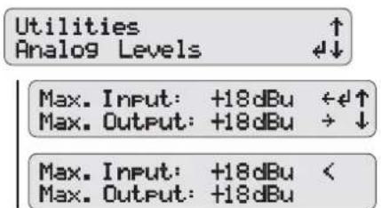
Menu option - ADMIN/Analog Levels
The FIRNET uses stacked AD converters to achieve >128 dB (A) input dynamic range.
Note: You must manually set analog levels to 18 dBu after a firmware update.
20 OUTPUT A to OUTPUT D Analog Audio Outputs
Use these three-pin XLR male sockets to route output signals to power amps. Pin assignments are pin 1 = ground, pin 2 = signal (+), and pin 3 = signal (-). These electronically balanced connectors' output impedance is 35 ohms.
The DA converters' output dynamic range is >125 dB (A). A menu option lets you adjust the maximum output level in four steps (6 dBu, 12 dBu, 18 dBu, 24 dBu) to match the levels of the FIRNET controller's output and the connected power amp's analog input.
Adjust the FIRNET's analog output signal's maximum level (Max. Output) to match the downstream power amp.
Heads up: Correct limiter settings ensure the FIRNET operates safely with the various power amplifiers that drive HK AUDIO loudspeakers. To this end, adjust Max. Output Level settings as follows:
Gain (L.A.B. FP10000Q): +26 dBu
Voltage Peak Limiter: 150 V, Soft Mode Max Output (Firnet): +18 dBu
Settings for HK AUDIO VX 2400 amps:
Gain VX 2400: +35 dBu Max Output ( Firnet): +6 dBu
Important note:: The FIRNET's limiter cannot effectively attenuate signals when set to other dBu levels, so connected speakers may be damaged or destroyed.
Menu Options
A General Survey of Menu Options:

Mute Output A/B/C/D
These control keys serve to mute individual outputs. Simply press and hold the Admin key while pressing key 1 to 4 to select and mute an output.

A General Survey of Control Keys:


Start Menu - Viewing Current Settings
The device begins booting as soon as it is -connected to the mains supply and powered up. The display first reads TEST, and then a < symbol wanders across the display. At the end of the boot sequence, the display indicates the current firmware for about two seconds.
Then the controller's start menu shows the -following parameters:
- Preset no.
• Controller name and LAN status - Current IP address
- Current scene
- Current routing
- Routing input
- Current input
- Current sample rate
• Current synchronization status - Current firmware version
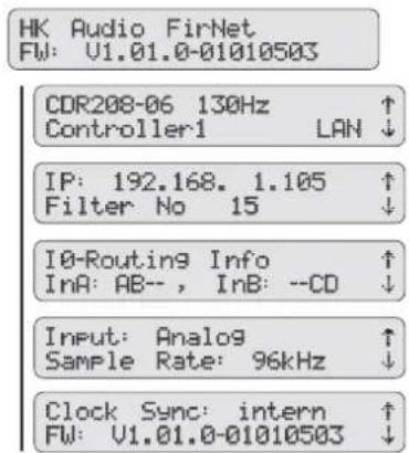
Adjusting Parameters
Controller Menus

Five menu options are available for editing individual parameters. Simply press the appropriate key to select a menu.
Speaker-Auswahl
A quick run-down on how to select the speaker series and the right filter for the connected speaker(s) follows.


Scenes - Loading and Saving Previously Stored Settings
Load Scene - Accessing Previously Stored Settings

Save Scene - Storing Settings as a Scene

Adjusting Levels
Adjusting Input Levels
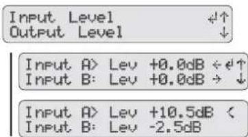
Adjusting Output Levels
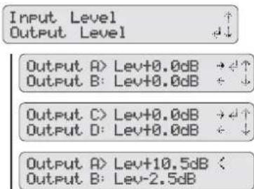
Delay/Phase
Adjusting Input Delays

Adjusting Output Delays

Selecting the Input Phase Position
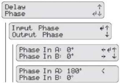
Selecting the Output Phase Position

Admin - Adjusting the -Remaining Parameters

Key Lock – Preventing - Unauthorized Access
Locking Keys

Input Options

Utilities: Delay, Temperature, Display Contrast, Controller Name

Analog Levels
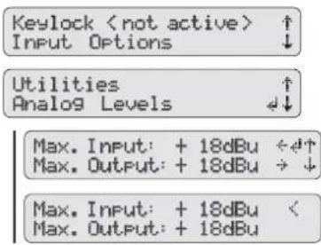
Technical Data FirNet™ Controller
| Connector Analog Input 3-pol. XLR female | |
| Pin assignments 1 = ground, 2 = Signal(+), 3 = Signal(-) | |
| Input impedance 9 k-ohm | |
| Maximum input level Variable; 6, 12, 18, and 24 dBu | |
| Dynamic range, input >128 dB (A) | |
| Digital input 3-pol. XLR female | |
| Pin assignments 1 = ground, 2 = Signal, 3 = Signal | |
| Input impedance 110 ohms | |
| Protocol AES 3 (AES/EBU) | |
| Clock rate 48 or 96 kHz, and 96 kHz internal | |
| Synchronization To an external source (slave mode) | |
| Digital output 3-pol. XLR male | |
| Pin assignments 1 = ground, 2 = Signal, 3 = Signal | |
| Output impedance 110 ohms | |
| Protocol AES 3 (AES/EBU) | |
| Signal processing Refresh signal form and level (Bypass at power failure) | |
| Analog outputs 3-pol. XLR male | |
| Pin assignments 1 = ground, 2 = Signal(+), 3 = Signal(-) | |
| Output impedance 35 ohms | |
| Maximum output level | Variable; 6, 12, 18, and 24 dBu |
| Dynamic range, output | >125 dB(A) |
| Mains voltage connector | Three-pole non-heating equipment connector |
| Mains voltage / frequency | 100 to 240 V / 50 - 60 Hz |
| Power consumption | 40 VA |
| Max. curr. cons. at 100 V mains voltage | 400 mA |
| Max. curr. cons. at 230 V mains voltage | 175 mA |
| Ethernet X port RJ-45, RJ-45, cross-connected | |
| Ethernet II port | RJ-45, RJ-45, direct-connected |
| Audio data (Linear Through mode) | |
| Frequency response (-1 dB) | 5.5 Hz to 34 KHz |
| THD+N (20 Hz bis 20 kHz) | AD>DA input level 21 dBu, R=100 k, 96 kHz 0,0012%-0,0013% |
| AES>DA input level -3dB FS, R=100k, 96 kHz 0,0010%-0,0012% | |
| Latency (incl. limiter): | AD > DA 96 KHz 3,15 ms |
| AD > AES/EBU 96 KHz | |
| AES/EBU > A 96 KHz | |
| + FIR filter | 5.8 ms (Cohedra / Coh. Compact) |
| Internal sampling rate | 96 kHz |
| Internal data format | 32 bit floating point |
| AD converter resolution | 28 Bit |
| DA converter resolution | 24 Bit |
| Temperature range -10°C to +70°C | |
| Weight | 3 kg · 6.,6 lbs. |
| Measurements (D x H x W) | 48 x 4.4 x 23.2 cm |
| 18-7/8 x 17-5/16 x 9-1/8" |
G Service
1 CADIS™ Replacement Parts
If you require a replacement part for HK AUDIO CADISTM equipment, please request it using the designation and part number indicated in the list below.
Note:
Please turn to your HK Audio dealer or the HK Audio distributor in your country if your equipment needs service. They stock the required spare parts. In the event of a defect, always indicate the defective device's serial number. This way the HK Audio service team can immediately find out if an update is available for your product.
Use original HK Audio replacement speakers and parts only. Most were developed especially for HK Audio products and are not available direct from speaker manufacturers.
Replacement parts list with separate numbers for black and white parts
| Designation black white | ||
| 1" HF driver 9940173 9940173 | ||
| Diaphragm 1" driver 9940190 9940190 | ||
| 15" woofer 9940184 9940184 | ||
| 8" woofer 9940261 9940261 | ||
| Connector panels | ||
| CAD 208 barrier strip 5200148 5200 | 54 | |
| CAD 208 barrier strip-triamped 5200 | 51 5200157 | |
| CAD 208 NL4 5200146 | 5200152 | |
| CAD 208 NL8 | 5200149 | 5200155 |
| CAD 208 PG | 5200147 | 5200153 |
| CAD 208 PG tri-amped | 5200150 | 5200156 |
| Blue wheels 100 mm | 9760158 | 9760158 |
| Rigging connector, CAD 115 Sub | 1006092 - | |
| Front grille CAD 115 Sub | 3400176 | 3400181 |
| Front grille CAD 208 | 3400175 | 3400182 |
| Rubber foot CAD 115 Sub | 9760009 | 9760009 |
| Quick- release pins | 9760184 | 9760184 |
| Housing CAD 115 Sub | 4000559 4000565 | |
| Housing CAD 208 | 9590150 4000558 | |
| Grip CAD 115 Sub | 9760189 / 9760190 | - |
| Rear rigging connector CAD 208 | 7000826 7000888 | |
| Subwoofer dolly | 1006400 | - |
Table 4: Replacement parts list, June 2009
2 A Look at the Required Tools
Three tools are all you need to service speakers:
• a 4-mm Allen (hex) wrench
• a Torx T25 wrench
• a Phillips head or power screwdriver

natural_image
Three different types of screwdrivers shown in black and gray, no text or symbols presentFig. 34: Required service tools
3 Replacing Loudspeakers and Voice Coils
Note on safety:
- Be sure to proceed with due care and caution when reassembling the speaker.
Note:
- To service a CADISTM CAD 208 cabinet, remove it from the rig and place it on its back on a level, stable base.
- When servicing a speaker, always ensure the speaker chassis' polarity is correct!
The following table shows the correct polarities:
| Wire color | Speaker | Polarity |
| Red | Tweeter, HF above | + |
| Black | Tweeter 2, HF below | - |
| Yellow | Woofer, center position, MF | + |
| White Woofer, center position, MF | - | |
| Green Subwoofer, outer position, LF | + | |
| Blue | Subwoofer, outer position, LF | - |
Caution! The "+" terminal of tweeter 2 and the "-" terminal of tweeter 1 are connected via a plugged in cable bridge (in a serial circuit)!
3.1 8" Woofers
Proceed as follows to replace the 8" speaker:
- Unfasten and remove the grille's four Phillips head screws on the housing's left and right panels.
- Lift the grille towards you to carefully disengage it from its frame.
- Unfasten the four Torx T25 screws from the right 8" speaker's chassis to removeit.
- Unfasten and remove the ten Torx T25 screws on the baffle board.
- Use the 4-mm Allen wrench to unfasten and remove the three hex head screws in the baffle board.
- Use the 4-mm Allen wrench to unfasten and remove the three each hex head screws securing the quick-release pins on the left and right panels.
- Unfasten and remove the two each Torx T25 screws on the left and right panels and detach the panels from the housing.
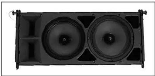
natural_image
Top-down view of a black rectangular speaker or audio device with two circular speakers, no visible text or symbols.Fig. 35: CAD 208 with the grille removed
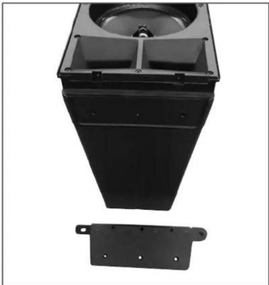
natural_image
Black plastic mechanical component with a circular top and two side mounting brackets (no text or symbols visible)Fig. 36: CAD 208 with the side panels detached
- Remove the entire baffle board from the housing and disconnect the wires.
- Place the dismantled baffle board face down on a surface where it won't slide around while you're working.
- Unfasten and remove the 8" speaker's four Torx T25 screws.
- Now that the speaker is detachable, disconnect the speaker wires.

natural_image
Black-and-white photo of a mechanical fan assembly with three circular components and a separate disassembled component (no visible text or symbols)Fig. 37: Dismantled CAD 208 baffle board with the woofer
When installing and connecting a replacement speaker, ensure that the polarity is correct!
A red dot marks the 8" speaker's positive terminal.
3.2 The 1" Drivers' Voice Coils
Proceed as follows to replace the voice coil:
- Unfasten and remove the grille's four Phillips head screws on the housing's left and right panels.
- Lift the grille towards you to carefully remove it from its frame.
- Unfasten and remove the ten Torx T25 screws on the baffle board.
- Use the 4-mm Allen wrench to unfasten and remove the three hex head screws in the baffle board.
- Use the 4-mm Allen wrench to unfasten and remove the three each hex head screws securing the quick-release pins on the left and right panels.
- Unfasten and remove the two each Torx T25 screws on the left and right panels and detach the panels from the housing.
- Remove the entire baffle board from the housing and disconnect the wires.
- Place the dismantled baffle board face down on a soft surface where it won't slide around while you're working.
- Unfasten and remove the defective HF driver's four Phillips head screws.
Now that the HF driver is detachable, disconnect the speaker wires.
Remove the HF driver and turn it so the magnet faces down.
- Unfasten and remove the four Phillips head screws on the HF driver's flange.
- Lift the HF driver's flange and remove it from the magnet. Now you can detach the voice coil unit and install a replacement part.

natural_image
Three mechanical components with mounting holes and bolts, shown from different angles (no text or symbols visible)Fig. 38: Voice coil removed from the CAD 208 HF driver
Note: The two HF drivers are wired in series!
Important note: Replace the voice coil in a clean working environment only. Be sure to keep dust and dirt out of the open driver. If despite your precautions particles manage to get in, use a strip of adhesive tape to remove them or carefully blow compressed air into the back of the driver to whisk the particles out. When installing the new voice coil, ensure it is centered properly.
Proceed as follows to check this: Close the cover of the voice coil housing and reconnect the wires (red = positive, black = negative).
Feed a sine wave signal with a frequency between 1000 Hz and 1500 Hz into the mid/high enclosure's input. Sweep through the frequency. If you hear any abrasive noise like crackling or scratching, the voice coil is not centered properly. Reopen the voice coil chassis and turn the voice coil a bit until it renders the signal cleanly!
H Appendix/Reference Library
1 CADIS™ FIRNET Controller Filter Sets
| Application (per side) Filter name Version Date | |||
| 4 x CAD 208 Fullrange CAD20 | 8-4 fullr 1 06-01-09 | ||
| 4 x CAD 208 + 2 x CAD 115 CAD | D208-4 100Hz 1 06-01-09 | ||
| 6 x CAD 208 Fullrange CAD20 | 8-6 fullr 1 06-01-09 | ||
| 6 x CAD 208 + 3 x CAD 115 CAD | D208-6 100Hz 1 06-01-09 | ||
| 8 x CAD 208 Fullrange CAD20 | 8-8 fullr 1 06-01-09 | ||
| 8 x CAD 208 + 4 x CAD 115 CAD | D208-8 100Hz 1 06-01-09 | ||
| 12 x CAD 208 Fullrange CAD20 | 8-4 fullr 1 06-01-09 | ||
| 12 x CAD 208 + 6 x CAD 115 CAD | D208-4 100Hz 1 06-01-09 | ||
| 16 x CAD 208 Fullrange CAD20 | 8-8 fullr 1 06-01-09 | ||
| 16 x CAD 208 + 8 x CAD 115 CAD | D208-8 100Hz 1 06-01-09 | ||
Table 5: CADIST™ FIRNET filter sets as of June 2009. You'll find more settings and controller setups on the download pages of our website at www.hkaudio.com.
This is to certify that
Cadis CAD 208, Cadis CAD 115 Sub
complies with the provisions of the Directive of the Council of the European Communities on the approximation of the laws of the Member States relating to electromagnetic compatibility according to EMC directive 2004/108/EC and low voltage directive 2006/95/EC.
This declaration of conformity of the European Communities is the result of an examination carried out by the Quality Assurance Department of STAMER GmbH in accordance with European Standards EN61000-6-1, EN61000-6-2, and EN 60065 for low voltage.

Magdeburger Str. 8, 66606 St. Wendel

Lothar Stamer Dipl.Ing.
Managing Director
St. Wendel, 06/02/2009
Version 2.0 08/2008
Inhalt:
A CADISTM-Lautsprecher 29
1 CAD 208 Mid/ High-Box 29
1 CADIS 208 Mid/ High-Cases ....31
E CADISTM Controlling Konzept....40
1 CAD 208 Mid/High-Box

natural_image
Black rectangular electronic device with mesh backrest and ventilation slots (no visible text or symbols)Abb. 1: CAD 208
Aufbau und Mechanik
0^, 1,5^, 3^, 4,5^, 6^, 7,5^, 9^, 10,5^, 12^, 13,5^ 15^
Gewicht
17,5 kg / 38,6 lbs.
natural_image
Black rectangular speaker with mesh grille and visible sound waves (no text or symbols)Abb. 2 Subwoofer CAD 115 Sub
Schalldruck @1m, max. calculated:
129 dB@ 10% THD Fullspace (2400 W Peak)
135 dB@ 10% THD Halfspace (2400 W Peak)
Anschlüsse: 2x Speakon NL 4
natural_image
Exterior view of a black industrial airbag with metal frame and wheels (no text or symbols visible)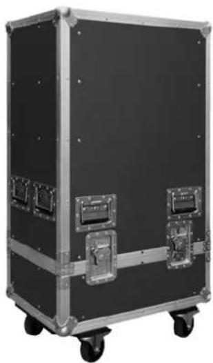
natural_image
Exterior view of a black industrial equipment box with metal frame and mounting brackets (no visible text or symbols)Abb. 3a: CAD 208-Cases
2 CAD 115 Sub-Rollbrett
natural_image
Black rectangular electronic component with four metallic wheels and mounting brackets (no text or symbols visible)Abb. 3b: CAD 115 Sub-Rollbrett
natural_image
Black industrial container or structure with multiple horizontal bands and a metal frame (no visible text or symbols)natural_image
Two stacked black electronic equipment units with visible ports and wiring, no text or symbols present.natural_image
3D rendering of a black rectangular mechanical component with four circular holes and a central rod (no text or symbols)Abb. 6: CADIS - Standard Flugrahmen

natural_image
3D rendering of a black rectangular frame with mounting brackets and a central vertical slot (no text or symbols)Abb. 7: CADIS - Verbinderrahmen
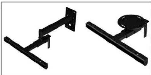
natural_image
Two black metal structural components with mounting flanges and a circular component on the right (no text or symbols visible)natural_image
Close-up of a mechanical clamp or spring with a coiled spring and handle (no text or symbols visible)natural_image
Two black-and-white images of industrial cable harnesses with hooks and straps (no text or symbols visible)natural_image
Close-up of a black mechanical component with a cylindrical shaft and flange (no text or symbols visible)natural_image
Close-up of a CAD Lab device with visible wiring and control buttons (no readable text or symbols)natural_image
Close-up of a metallic chain link with two hanging rings and bolts (no text or symbols visible)natural_image
Close-up of a mechanical device with a metallic blade and clamped components (no visible text or symbols)natural_image
Interior view of a dual-chamber electronic device with labeled ports and cables (no readable text or symbols)natural_image
Large black industrial equipment with vertical supports and a suspended load, no visible text or symbolsnatural_image
Stacked black industrial equipment units suspended by metal chains (no visible text or symbols)natural_image
Black-and-white photo of four stacked electronic equipment units with visible wiring and control panels (no readable text or symbols)natural_image
Black industrial structure with multiple vertical panels and mounting brackets, suspended by a metal rod (no visible text or symbols)natural_image
Curved black mechanical component with a connecting rod (no visible text or symbols)natural_image
Black mechanical device with coiled cable and two spherical components (no visible text or symbols)Abb. 21: CAD 115 Sub Montage-Set

natural_image
Close-up of a metallic clamp securing a U-shaped wire against a dark background (no text or symbols visible)natural_image
Stacked black industrial equipment unit with three vertical panels and mounting brackets (no visible text or symbols)natural_image
Stacked black rectangular storage units on a white background (no text or symbols visible)Abb. 26: FirNet™ - Öffnen des Dialogfeldes Update Scene+ Filter Settings
![Open Library Fines Library Select All Select Name Score + Fines Library Name Series 0 0 0 0 0 0 0 0 0 0 0 0 0 0 0 0 0 0 0 0 0 0 0 0 0 0 0 0 0 0 0 0 0 0 0 0 0 0 0 0 0 0 0 0 0 0 0 0 0 0 188 Fines 1.5 Options Systems in: LAD-PTC23332.1.1.1.1.1.1.1.1.1.1.1.1.1.1.1.1.1.1.1.1.1.1.1.1.1.1.1.1.1.1.1.1.1.1.1.1.1.1.1.1.1.1.1.1.1.1.1.1.1.1.2 DIF/STOCKENIX_268_PPI_AKPCX.PG. Denspace: Design: Layer 7 - File Library / Alt... Options: Quick Quick Response... OK Audio LPAP [x] ... Adobe Photoshop D:\MSC Projects in R... 19:24](/content/2026/05/911917/images/a97fabc62a829140bff387995452a935819a987d22c30e475de9ed6a8855f5cd.jpg)
Menüpunkt - ADMIN/Input Options/ Input Source:

Mute Output A/B/C/D

Utilities: Delay, Temperature, Display Contrast, Controller Name

Analog Levels

Technical Data FirNet™ Controller
natural_image
Three different types of screwdrivers shown in black and gray, no text or symbols presentnatural_image
Top-down view of a black rectangular speaker with two circular speakers, no text or symbols visiblenatural_image
Black plastic mechanical component with a circular top and side mounting bracket, plus a separate black metal bracket (no text or symbols visible)natural_image
Black-and-white photo of a mechanical fan assembly with three circular components and a separate disassembled component (no visible text or symbols)natural_image
Three mechanical components with bolts and a central hub, shown from different angles (no text or symbols visible)radar
| Angle | 3.76.3 | 4000 | 5398.2 | |---|---|---|---| | 0 | 0 | 0 | 0 | | 30 | 0 | 0 | 0 | | 60 | 0 | 0 | 0 | | 90 | 0 | 0 | 0 | | 120 | 0 | 0 | 0 | | 150 | 0 | 0 | 0 | | 180 | 0 | 0 | 0 | | 210 | 0 | 0 | 0 | | 240 | 0 | 0 | 0 | | 270 | 0 | 0 | 0 | | 300 | 0 | 0 | 0 | | 330 | 0 | 0 | 0 | | 360 | 0 | 0 | 0 | | 390 | 0 | 0 | 0 | | 420 | 0 | 0 | 0 | | 450 | 0 | 0 | 0 | | 480 | 0 | 0 | 0 | | 510 | 0 | 0 | 0 | | 540 | 0 | 0 | 0 | | 570 | 0 | 0 | 0 | | 600 | 0 | 0 | 0 | | 630 | 0 | 0 | 0 | | 660 | 0 | 0 | 0 | | 690 | 0 | 0 | 0 | | 720 | 0 | 0 | 0 | | 750 | 0 | 0 | 0 | | 780 | 0 | 0 | 0 | | 810 | 0 | 0 | 0 | | 840 | 0 | 0 | 0 | | 870 | 0 | 0 | 0 | | 900 | 0 | 0 | 0 | | Note: The data provided in the image is a representation of the original data and may not be extracted from the code. The numbers '3.76.3' and '4.598.2' are estimated based on the provided code format. There is no additional data series or trends plotted in this view. The values in the chart are estimated based on the provided code format.radar
| Angle | 6276.7 | 0000 | |---|---|---| | 0 | 150 | 150 | | 30 | 145 | 145 | | 60 | 140 | 140 | | 90 | 135 | 135 | | 120 | 130 | 130 | | 150 | 125 | 125 | | 180 | 120 | 120 | | 210 | 115 | 115 | | 240 | 110 | 110 | | 270 | 105 | 105 | | 300 | 100 | 100 | | 330 | 95 | 95 | | 360 | 90 | 90 | | 390 | 85 | 85 | | 420 | 80 | 80 | | 450 | 75 | 75 | | 480 | 70 | 70 | | 510 | 65 | 65 | | 540 | 60 | 60 | | 570 | 55 | 55 | | 600 | 50 | 50 | | 630 | 45 | 45 | | 660 | 40 | 40 | | 690 | 35 | 35 | | 720 | 30 | 30 | | 750 | 25 | 25 | | 780 | 20 | 20 | | 810 | 15 | 15 | | 840 | 10 | 10 | | 870 | 5 | 5 | | 900 | 0 | 0 | The chart displays a polar coordinate system with two data series: '6276.7' and '0000'. The x-axis represents the angle in degrees (from -180° to +180°). The y-axis represents the magnitude of the measured variable. The data is plotted as a line connecting the points along the circular axis. There is no legend categories provided in the image.CAD 115 Sub Phase Response

HK Audio® • Postfach 1509 • 66595 St. Wendel Germany • info@hkaudio.com • www.hkaudio.com International Inquiries: fax +49-68 51-905 215 international@hkaudio.com
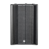
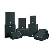
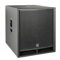
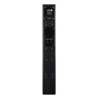
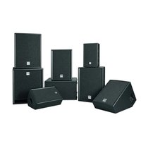
- Important Safety Instructions Before connecting, read instructions
- Important Advice on Safety! Please read before use and keep for later use!
- WARNING:
- MAINS CONNECTION:
- PLACE OF INSTALLATION:
- A CADISTM Speaker Cabinets 5
- B CADISTM Transport Solution 7
- C Rigging the CADISTM System 8
- D CADISTM Aiming Software Setups with EASE Focus 16
- E Controlling CADISTM 16
- F Controllers and Controller Software....17
- G Service....25
- H Appendix/Reference Library.... 27
- Index of Figures:
- Index of Tables:
- A CADIS™ Speaker Cabinets
- CAD 208 Mid/High Enclosure
- Design and Construction
- Electrical and Acoustical Data
- Connections
- a: Connector panel with two Speakon NL 4 ports (Input/Through)
- b: Connector panel with binding posts
- c: Connector panel with PG glands
- Technical Data, CAD 208
- Accessories:
- Subwoofer CAD 115 Sub
- Design and Construction of the Subwoofer
- Technical Data, CAD 115 Sub
- B CADIS™ Transport Solution
- CAD 208 Cases
- CAD 115 Sub Dolly
- Dimensions and Weights of CAD 208 Cases
- Case 4x CAD 208:
- Case 8x CAD 208:
- C Rigging the CADIS™ System
- Use
- Intended Use
- Misuse
- Warranty and Liability
- Important Notes on Safety!
- Responsibilities of the Operator
- Storage, Maintenance, Inspection and Repair of CADIS™ Rigging Hardware
- Storage and safekeeping when not in use
- Inspections
- Maintenance
- Repair
- Technical Specifications of CADIS™ Rigging Hardware
- Maximum Number of Flown CAD 208 Mid/High Enclosures
- Maximum Number of Flown CADISTM CAD 115 Subs
- Caution: Flying more than two subwoofers in stacked array with the connector frame voids the safety standards authority TÜV's certification!
- Note: Ensure that you add the weights of chain hoists, motors, cables and further stops to determine total weight!
- Pick-points for Flying CADIS ™ Enclosures
- Structural Modifications of CADIS™ Rigging Hardware
- Original HK AUDIO Accessories
- Initiation and Operation
- Flown Applications and Components of CADIS™ Rigging Hardware
- CADISTM rigging hardware consists of the following parts:
- Adjusting the Set Angle between Two CAD 208 Mid/High Enclosures
- Compression Mode
- How does this work?
- Preparations
- Mounting the Rigging Frame
- Rigging Additional CAD 208 Enclosures
- Hoisting the System
- Fixed Mode
- Flying CAD 115 Subwoofers
- Components
- As an Independent Bass Array on a Second RiggingFrame
- Rigging
- In Combination with CAD 208 Mid/High Enclosures
- With a Standard Rigging Frame
- With CAD 115 Subwoofers
- Operating the System
- Connecting Speaker Cords
- Checking Individual Mid/High Enclosures
- Configuring the Controller Network Using Audio Controller Software
- Tearing Down and Transporting the System
- D CADIS™ Aiming Software Setups with EASE Focus
- Acoustic Simulation of CADIS™ Setups with EASE Focus and the CADIS-GLL for EASE
- E Controlling CADIS TM
- F Controllers and Controller Software
- FirNet™ Controller
- Getting started
- Fundamentals
- PC settings
- Installing LIPAN software
- Loading filter banks
- Loading an entire filter bank
- Loading a single filter
- FirNet Display
- FirNet Menu Keys
- FirNet Channel Mute
- Control features Front
- SPEAKER Key
- SCENE Key
- LEVEL Key
- DELAY/PHASE Key
- ADMIN Key
- AES IN LED Display
- EXT SYNC LED Display
- INPUT LED Displays (10 LEDs, green/yellow/red)
- LCD
- OUTPUT LED Displays (10 LEDs, green/yellow/red)
- Back Key
- Navigation Keys
- Reset Button
- Soft Reset and Hard Reset key combinations
- Soft Reset: (Admin+Back+Enter for 3 seconds)
- Hard Reset: Factory default
- Rear Panel Connectors
- 100-240 V\~ / 50-60 Hz Mains
- GPIO
- Ethernet PC Control Ports
- Cabling:
- AES/EBU IN Digital Audio Input
- Input-Output Signal Routing:
- AES/EBU OUT Digital Audio Output
- Synchronization Ports for Analog Audio Signals:
- INPUT A, INPUT B Analog Audio Inputs
- OUTPUT A to OUTPUT D Analog Audio Outputs
- Menu Options
- A General Survey of Menu Options:
- Mute Output A/B/C/D
- A General Survey of Control Keys:
- Start Menu - Viewing Current Settings
- Speaker-Auswahl
- Delay/Phase
- Admin - Adjusting the -Remaining Parameters
- G Service
- CADIS™ Replacement Parts
- Note:
- A Look at the Required Tools
- Replacing Loudspeakers and Voice Coils
- Note on safety:
- 8" Woofers
- Proceed as follows to replace the 8" speaker:
- The 1" Drivers' Voice Coils
- Proceed as follows to replace the voice coil:
- Note: The two HF drivers are wired in series!
- H Appendix/Reference Library
- CADIS™ FIRNET Controller Filter Sets
- Cadis CAD 208, Cadis CAD 115 Sub
- Inhalt:
- CAD 208 Mid/High-Box
- Aufbau und Mechanik
- CAD 115 Sub-Rollbrett
Brand : HK AUDIO
Model : Cadis
Category : Speaker