
DES-1526 - Network switch D-LINK - Free user manual and instructions
Find the device manual for free DES-1526 D-LINK in PDF.


| Product Type | Smart Managed Switch |
| Brand | D-Link |
| Model | DES-1526 |
| Number of Ports | 24 ports 10/100BASE-TX + 2 combo Gigabit ports (1000BASE-T/SFP) |
| Port Type | RJ-45 10/100 Mbps, SFP Gigabit |
| Management Features | VLAN, QoS, IGMP Snooping, Spanning Tree, Port Mirroring, Loop Detection |
| Switching Capacity | 8.8 Gbps |
| Maximum Forwarding Rate | 6.55 Mpps (64-byte packets) |
| Buffer Memory | 512 KB |
| MAC Address Table | 8,000 entries |
| Power Supply | Internal, 100-240 V AC, 50/60 Hz |
| Power Consumption | 13.5 W (max) |
| Dimensions (W x D x H) | 280 x 180 x 44 mm |
| Weight | 1.5 kg |
| Operating Temperature | 0°C to 40°C |
| Operating Humidity | 10% to 90% non-condensing |
| Network Standards | IEEE 802.3, 802.3u, 802.3ab, 802.3z, 802.3x, 802.1p, 802.1Q, 802.1w, 802.1D |
| Mounting | Desktop or 19-inch rack (mounting kit included) |
| Package Contents | DES-1526 Switch, power cord, rack mount kit, quick installation guide, documentation CD |
| Maintenance and Cleaning | Disconnect before cleaning; use a dry lint-free cloth; do not use solvents |
| Safety | Do not expose to water or excessive heat; respect specified power supply voltages |
| Spare Parts and Repairability | No user-serviceable parts; contact D-Link technical support in case of failure |
| Warranty | Manufacturer warranty 3 years (according to conditions) |
| Recycling | Do not dispose of with household waste; comply with local WEEE recycling regulations |
Frequently Asked Questions - DES-1526 D-LINK
User questions about DES-1526 D-LINK
0 question about this device. Answer the ones you know or ask your own.
Ask a new question about this device
Download the instructions for your Network switch in PDF format for free! Find your manual DES-1526 - D-LINK and take your electronic device back in hand. On this page are published all the documents necessary for the use of your device. DES-1526 by D-LINK.
USER MANUAL DES-1526 D-LINK
Web-Smart 26-Port Ethernet Switch with
24 10/100Mbps 802.3af Power Over Ethernet Ports
&
2 10/100/1000Mbps Combo Gigabit Ethernet Ports
Manual
First edition
Building Networks for People
FCC Warning
This equipment has been tested and found to comply with the limits for a Class A digital device, pursuant to Part 15 of the FCC Rules. These limits are designed to provide reasonable protection against harmful interference when the equipment is operated in a commercial environment. This equipment generates, uses, and can radiate radio frequency energy and, if not installed and used in accordance with this manual, may cause harmful interference to radio communications. Operation of this equipment in a residential area is likely to cause harmful interference in which case the user will be required to correct the interference at his own expense.
CE Mark Warning
This is a Class A product. In a domestic environment, this product may cause radio interference in which case the user may be required to take adequate measures.
Warnung!
Table of Contents......iii
About This Manual....1
Purpose....1
Terms/Usage .... 1
Introduction....2
Fast Ethernet Technology....2
Gigabit Ethernet Technology....3
Switching Technology....4
VLAN (Virtual Local Area Network)......5
Power over Ethernet (PoE) 6
Features......6
Unpacking and Installation....8
Unpacking....8
Installation....8
Installing the Switch on a Desktop....9
Installing the Switch on a Rack....10
Connecting Network Cables 11
AC Power....12
Identifying External Components....14
Front Panel....14
LED Indicator:....14
10/100Mbps PoE Ports (Port 1\~24):....14
1000BASE-T Gigabit Ethernet Ports (Port 25\~26): ...... 15
mini-GBIC Ports (Port 25F\~26F):....15
Reset:....16
Rear Panel....16
Understanding LED Indicators....17
System LEDs ....17
POWER:....17
Power Maximum (PWR MAX)....17
CPU: Management Indicator....18
Fast Ethernet PoE Port Status LEDs (Port 1 \~ 24)......18
Link/ACT: Link/Activity 18
100Mbps....18
PoE Status....18
Gigabit Ethernet Port Status LEDs 19
Link/ACT: Link/Activity 19
1000Mbps....19
100Mbps....19
mini-GBIC (Use Combo ports or SFP)....19
Configuration 20
Installing the Web Management Utility....20
Discovery List....21
Monitor List....22
View Trap 23
Add Item....24
Delete Item....24
Device Setting....24
Configuration Setting....24
Password Change 25
Firmware Upgrade....26
Web Access ......26
Toolbar....27
File TAB....27
View TAB....27
Option TAB 28
Help TAB....28
Configuring the Switch....28
Login....29
Setup Menu....31
Configuring Setup Setting....32
Port Settings 32
802.1Q VLAN Settings (Virtual Local Area Network)......34
Trunk Setting....37
Mirror Setting 38
SNMP Setting....39
PoE Setting....47
Device Status....50
Statistics 52
System Setting....53
Trap Setting 55
Set Password ....57
Backup Setting 58
Reset Setting....59
Logout 59
Technical Specifications....58
Congratulations on your purchase of the DES-1526. This Switch integrates 100Mbps Fast Ethernet and 10Mbps Ethernet network capabilities in a highly flexible package. Since this Switch's Port-1 to Port-24 are Power over Ethernet (PoE) ports, it will automatically detect the presence of IEEE 802.3af-compliant devices and will provide power through these PoE ports. The Switch provides up to 15.4Watts per port and can be connected to WLAN access points, IP phones, video cameras, and other PD devices. The Switch will automatically detect the network appliance's requirements, and the Switch will supply the required power current to each appliance.
Purpose
Thismanualdiscusses how to install your DES-1526.
Terms/Usage
In this manual, the term “Switch” (first letter upper case) refers to your DES-1526 and “switch” (first letter lower case) refers to other Ethernet switches.
This chapter describes the features of the DES-1526 and some background information about Fast Ethernet, Gigabit Ethernet, Switching, VLAN, and Power over Ethernet technologies.
Fast Ethernet Technology
The growing importance of LANs and the increasing complexity of desktop computing applications are fueling the need for high performance networks. A number of high-speed LAN technologies have been proposed to provide greater bandwidth and improve client/server response times. Among them, 100BASE-T (Fast Ethernet) provides a non-disruptive, smooth evolution from the current 10BASE-T technology. The non-disruptive and smooth evolution nature, and the dominating potential market base, virtually guarantees cost-effective and high performance Fast Ethernet solutions.
100Mbps Fast Ethernet is a standard specified by the IEEE 802.3 LAN committee. It is an extension of the 10Mbps Ethernet standard with the ability to transmit and receive data at 100Mbps, while maintaining the CSMA/CD Ethernet protocol. Since 100Mbps Fast Ethernet is compatible with all other 10Mbps Ethernet environments, it provides a straightforward upgrade and takes advantage of the existing investment in hardware, software, and personnel training.
Gigabit Ethernet Technology
Gigabit Ethernet is an extension of IEEE 802.3 Ethernet utilizing the same packet structure, format, and support for CSMA/CD protocol, full-duplex, flow control, and management objects, but with a tenfold increase in theoretical throughput over 100Mbps Fast Ethernet and a one hundred-fold increase over 10Mbps Ethernet. Since it is compatible with all 10Mbps and 100Mbps Ethernet environments, Gigabit Ethernet provides a straightforward upgrade without wasting a company's existing investment in hardware, software, and trained personnel. The increased speed and extra bandwidth offered by Gigabit Ethernet are essential to coping with the network bottlenecks that frequently develop as computers and their busses get faster and more users use applications that generate more traffic. Upgrading key components, such as your backbone and servers to Gigabit Ethernet can greatly improve network response times as well as significantly speed up the traffic between your sub-networks. Gigabit Ethernet enables support for video conferencing, complex imaging, and similar data-intensive applications. Likewise, since data transfers occur 10 times faster than Fast Ethernet, servers outfitted with Gigabit Ethernet NIC's are able to perform 10 times the number of operations in the same amount of time. In addition, the phenomenal bandwidth delivered by Gigabit Ethernet is the most cost-effective method to take advantage of today and tomorrow's rapidly improving switching and routing internetworking technologies.
Switching Technology
Another approach to pushing beyond the limits of Ethernet technology is the development of switching technology. A switch bridges Ethernet packets at the MAC address level of the Ethernet protocol transmitting among connected Ethernet or Fast Ethernet LAN segments.
Switching is a cost-effective way of increasing the total network capacity available to users on a local area network. A switch increases capacity and decreases network loading by dividing a local area network into different segments, which do not compete with each other for network transmission capacity.
The switch acts as a high-speed selective bridge between the individual segments. The switch, without interfering with any other segments, automatically forwards traffic that needs to go from one segment to another. By doing this the total network capacity is multiplied, while still maintaining the same network cabling and adapter cards.
Switching LAN technology is a marked improvement over the previous generation of network bridges, which were characterized by higher latencies. Routers have also been used to segment local area networks, but the cost of a router, the setup, and maintenance required make routers relatively impractical. Today switches are an ideal solution to most kinds of local area network congestion problems.
VLAN (Virtual Local Area Network)
A VLAN is a group of end-stations that are not constrained by their physical location and can communicate as if a common broadcast domain, a LAN. The primary utility of using VLAN is to reduce latency and the need for routers, using faster switching instead. Other VLAN utility includes:
◆ Security: Security is increased with the reduction of opportunity in eavesdropping on a broadcast network because data will be switched to only those confidential users within the VLAN.
◆ Cost Reduction: A VLAN can be used to create multiple broadcast domains, thus eliminating the need of expensive routers.
◆ 802.1Q VLAN: The VLAN tagging option is a standard set by the IEEE to facilitate the spanning of VLANs across multiple switches. (Reference: IEEE Std 802.1Q-1998 Virtual Bridged Local Area Networks.)
Power over Ethernet (PoE)
Power over Ethernet (PoE) integrates power and data onto one single cabling infrastructure, eliminating the need to have AC power available at all locations.
Power and Data are integrated onto the same cable. Supporting category 5/5e up to 100 Meters, PoE will provide power to PoE compatible devices, such as IP telephones, wireless LAN access points, and IP security cameras.
PoE is already widely adopted in the market, saving up to 50% of overall installation costs by eliminating the need to install separate electrical wiring and power outlets.
Features
◆ 24×10/100Mbps Auto-negotiation Fast Ethernet RJ-45 ports PoE enabled
◆ 2 x 1000BASE-T/mini-GBIC combo Gigabit Ethernet ports
◆ Compliant with 802.3af specification
◆ Supports PoE power up to 15.4W for each PoE port
◆ Supports PoE power maximum 170W for the device
◆ Supports PoE Powered Device (PD) classification identify
◆ Each port supports auto MDI/MDIX, so there is no need to use cross-over cables or an up-link port
◆ Full-duplex transfer mode for speed of 10Mbps, 100Mbps, and 1000Mbps
◆ Half-duplex transfer mode for speed of 10Mbps and 100Mbps
◆ Wire speed reception and transmission
◆ Store-and-Forward switching scheme capability to support rate adaptation and ensure data integrity
◆ Up to 4K unicast addresses entities per device, self-learning, and table aging
◆ 768KBytes packet buffer
◆ Supports IEEE 802.3x flow control for full-duplex mode ports
◆ Supports Back-pressure flow control for half-duplex mode ports
◆ Supports 802.1Q VLAN
◆ Supports Port-based Trunking
◆ Supports Port-mirroring
◆ Supports Port-setting for Speed/Disable, Flow control, and Port based QoS (Quality of Service)
◆ Easy configuration via Web Browser
◆ Easy setting via Web Management Utility
◆ Standard 19" Rack-mount size
This chapter provides unpacking and installation information for the Switch.
Unpacking
Open the shipping cartons of the Switch and carefully unpacks its contents. The carton should contain the following items:
One DES-1526
One AC power cord, suitable for your area's electrical power connections
◆ Four rubber feet to be used for shock cushioning
◆ Screws and two mounting brackets
◆ CD-ROM with Web Management Utility and Manual
If any item is found missing or damaged, please contact your local reseller for replacement.
Installation
The site where you install the Switch stack may greatly affect its performance. When installing, consider the following pointers:
◆ Install the Switch in a fairly cool and dry place. See Technical Specifications for the acceptable temperature and humidity operating ranges.
◆ Install the Switch in a site free from strong electromagnetic field generators (such as motors), vibration, dust, and direct exposure to sunlight.
Leave at least 10cm (4 in.) of space at the front and rear of the Switch for ventilation.
◆ Install the Switch on a sturdy, level surface that can support its weight, or in an EIA standard-size equipment rack. For information on rack installation, see the next section, titled Rack Mounting.
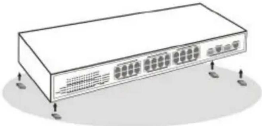
When installing the Switch on a level surface, attach the rubber feet to the bottom of each device. The rubber feet cushion the Switch and protect the Switch case from scratching.
Installing the Switch on a Desktop
When installing the Switch on a desktop or shelf, the rubber feet included with the Switch should first be attached. Attach these cushioning feet on the bottom at each corner of the device. Allow enough ventilation space between the Switch and any other objects in the vicinity.
natural_image
Illustration of a network switch device with multiple ports and ventilation slots (no text or labels)Figure 1. Installed on a Desktop
Installing the Switch on a Rack
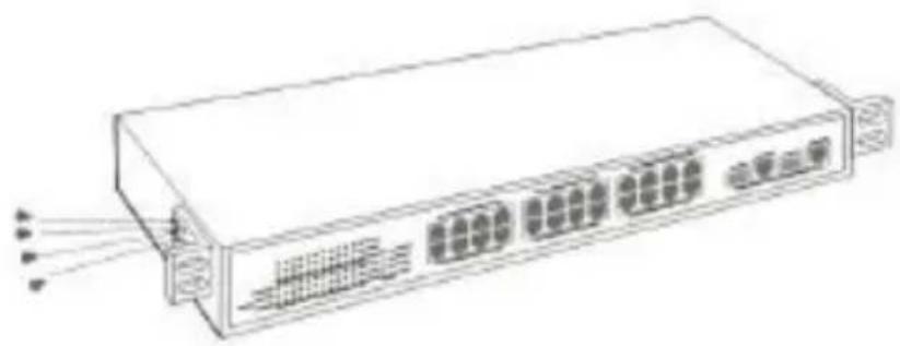
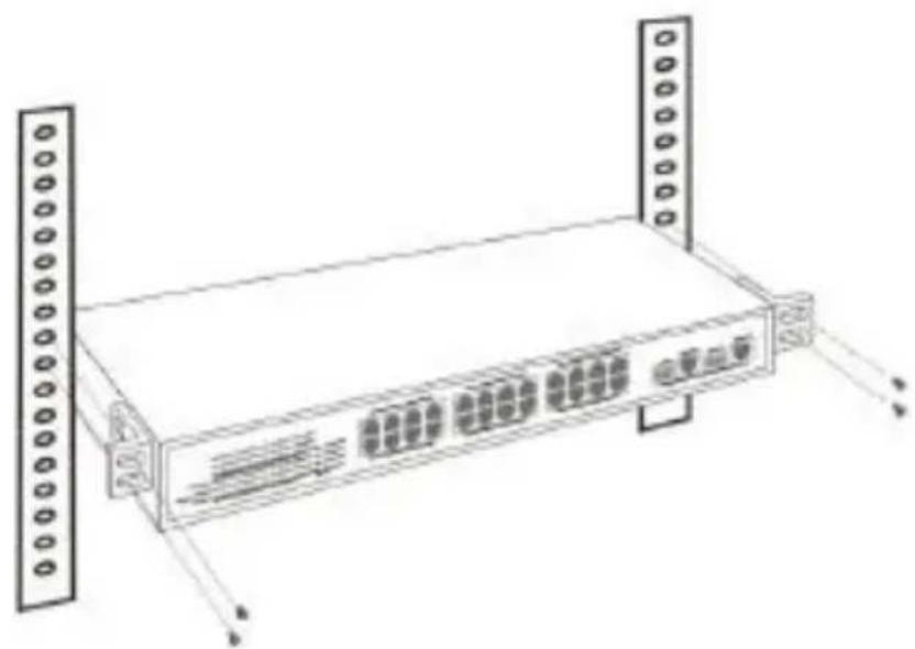
The Switch can be mounted in an EIA standard-size, 19-inch rack, which can be placed in a wiring closet with other equipment. Attach the mounting brackets at the Switch's front panel (one on each side), and secure them with the provided screws.
natural_image
Line drawing of a server rack with multiple ports and connectors (no text or symbols)Figure 2. Combine the Switch with the provided screws.
Then, use screws provided with the equipment rack to mount each switch in the rack.
natural_image
Line drawing of a server rack with multiple ports and connectors (no text or symbols)Connecting Network Cables
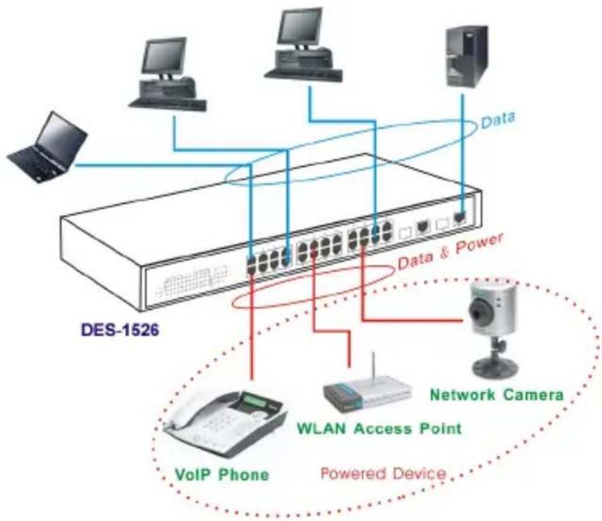
The Switch supports 24 10/100BASE-TX Fast Ethernet PoE enabled ports and 2 1000BASE-T/mini-GBIC combo ports. These 24 PoE ports will be automatically activated when a compatible terminal is identified. The Switch will supply power through the PoE port to the connected PD.
For Legacy devices that are not yet compatible, the PoE port will not offer the power to these devices. This feature allows users to freely and safely mix legacy and Power over Ethernet compatible devices on their network.
The Switch supports 10Mbps Ethernet or 100Mbps Fast Ethernet and it runs both in half- and full-duplex mode using two pairs of Category 5 cables.
The Switch also supports 2 1000BASE-T/mini-GBIC combo Gigabit Ethernet ports. When using the RJ-45 ports, it runs in Auto-negotiation mode with 10/100Mbps that runs in both half- and full-duplex mode and 1000Mbps that runs in full-duplex mode using four pair Category 5. When using the mini-GBIC ports, it runs in optional 1000BASE-SX/LX fiber connectivity with mini-GBIC transceiver module. The Combo Gigabit Ethernet port will run only one of the mini-GBIC ports or RJ-45 ports. The mini-GBIC port priority is higher than the RJ-45 port, therefore if both the mini-GBIC port and RJ-45 port are connected, then only the mini-GBIC will activate.
These RJ-45 ports are Auto-MDI type ports. The Switch can auto transform to MDI-II or MDI-X type, so you can just make an easy connection without worrying if you are using a standard or crossover RJ-45 cable.
flowchart
graph TD
    A[" laptop "] --> B[" Data "]
    C[" VoIP Phone "] --> D[" Network Camera "]
    E[" Wireless Access Point "] --> F[" Data & Power "]
    G[" DES-1526 "] --> B
    G --> D
    G --> F
    style A fill:#f9f,stroke:#333
    style C fill:#f9f,stroke:#333
    style E fill:#f9f,stroke:#333
    style G fill:#ccf,stroke:#333
    style B fill:#ccf,stroke:#333
    style D fill:#ccf,stroke:#333
    style F fill:#ccf,stroke:#333
    style G fill:#ccf,stroke:#333
Figure 4. Connecting Network Cables
AC Power
The Switch uses the AC power supply 100-240V AC, 50-60 Hz. The power switch is located at the rear of the unit adjacent to the AC power connector and the system fan. The Switch's power supply will adjust to the local power source automatically and may
be turned on without having any or all LAN segment cables connected.
IDENTIFYING EXTERNAL COMPONENTS
This chapter describes the front panel, rear panel, and LED indicators of the Switch.
Front Panel
The figure below shows the front panels of the Switch.

Figure 5. Front panel view
LED Indicator:
Comprehensive LED indicators display the status of the Switch and the network (see the LED Indicators chapter below).
10/100Mbps PoE Ports (Port 1\~24):
These ports are PoE enable ports. These PoE ports will be automatically activated when a compatible terminal is identified, and the PoE port will supply power to the connected PoE device.
The Switch PoE function supports PoE ports priority management. When there is a system power shortage with the PD, the Switch will enforce the PoE port priority management; the lower port number will have the higher priority than the higher port number, Port 1 > Port 2 > ... > Port 24.
For legacy devices that are not yet compatible, the PoE port will not offer the power to these devices. This feature allows users to freely and safely mix legacy and Power over Ethernet compatible devices on their network.
These ports support network speeds of either 10Mbps or 100Mbps, and can operate in half- and full-duplex transfer modes. These ports also support the automatic MDI/MDIX crossover detection function, providing true “plug and play” capability. Just plug-in the network cable to the Switch directly and regardless if the end node is a NIC (Network Interface Card) or switch and Switch.
1000BASE-T Gigabit Ethernet Ports (Port 25\~26):
The Switch is equipped with two Gigabit twisted pair ports, supported auto negotiable 10/100/1000Mbps and auto MDI/MDIX crossover detection function. These two ports can operate in half-duplex mode for 10/100Mbps and full-duplex mode for 10/100/1000Mbps.
Note: When the port is set to “Forced Mode”, the Auto MDI/MDIX will be disabled.
mini-GBIC Ports (Port 25F\~26F):
The Switch is equipped with two mini-GBIC ports, which supports optional 1000BASE-SX/LX mini-GBIC modules.
Note: Port 25 and 26 are the same ports with the mini-GBIC Port 25F and 26F ports, when plug in the mini-GBIC module, the device will activate mini-GBIC, and the RJ-45 port will be disabled.
Reset:
The Reset button is to reset all settings back to the factory defaults.
Note: Be sure that you record the settings of your device, or else all settings will be erased when pressing the “Reset” button.
Rear Panel

natural_image
Simple line drawing of a rectangular device with a small socket on top (no text or symbols)Figure 6. Rear panel of the Switch
AC Power Connector:
This is a three-pronged connector that supports the power cord. Plug in the female connector of the provided power cord into this connector, and the male into a power outlet. Supported input voltages range from 100-240V AC at 50-60Hz.
The front panel LEDs provide instant status feedback, and helps monitor and troubleshoot when needed.
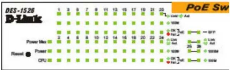
Figure 7. LED indicators of the Switch
System LEDs
POWER:
| On : | When the Power LED lights on, the Switch is receiving power. |
| Off : | When the Power turns off or the power cord has improper connection. |
Power Maximum (PWR MAX)
| On : | When the system power resource remain <=15.4W (the system power consumption >= 155W), the LED will be on, the system will not provide power to the additional POE PD inserted. |
| Off : | When the system has enough power more then 15.4W (the system power consumption <155W). |
CPU: Management Indicator
| Blinking : | When the CPU is working, the CPU LED is blinking. |
| On/Off : | The CPU is not working. |
Fast Ethernet PoE Port Status LEDs (Port 1 \~ 24)
Link/ACT: Link/Activity
| On : | When the Link/ACT LED lights on, the respective port is successfully connected to an Ethernet network. |
| Blinking : | When the Link/ACT LED is blinking, the port is transmitting or receiving data on the Ethernet network. |
| Off : | There is no link. |
100Mbps
| On : | When the 100Mbps LED lights on, the respective port is connected to a 100Mbps Fast Ethernet network. |
| Off : | When the respective port is connected to a 10Mbps Ethernet network. |
PoE Status
| Green : | When the PoE powered device (PD) is connected and the port supplies power normally. |
| Red : | When the PoE port have the following failure happens:● PoE power circuit shortage.● Power over current: over the power current of PD's classification.● Out of PoE voltage of 44 ~ 57 VDC output.● Cost fail. |
| Off : | No PoE powered device (PD) connected or unplugged the PoEoutput port. |
Gigabit Ethernet Port Status LEDs
Link/ACT: Link/Activity
| On : | When the Link/ACT LED lights on, the respective port is successfully connected to an Ethernet network. |
| Blinking : | When the Link/ACT LED is blinking, the port is transmitting or receiving data on the Ethernet network. |
| Off : | There is no link. |
1000Mbps
| On : | When the 1000Mbps LED lights on, the respective port is connected to a 1000Mbps Gigabit Ethernet network. |
| Off : | When the respective port is connected to a 10Mbps Ethernet or 100Mbps Fast Ethernet network. |
100Mbps
| On : | When the 100Mbps LED lights on, the respective port is connected to a 100Mbps Fast Ethernet network. |
| Off : | When the respective port is connected to a 10Mbps Ethernet or 1000Mbps Gigabit Ethernet network. |
mini-GBIC (Use Combo ports or SFP)
| On : | When the mini-GBIC module is installed and connected to a network, the mini-GBIC LED lights on. |
| Off : | No mini-GBIC module installed. |
Through the Web browser you can configure Switch functions such as VLAN, Trunking, and QoS... etc.
With the attached Web Management Utility, you can easily discover all the Web Management Switches, assign the IP Address, changing the password, and upgrade new firmware.
Installing the Web Management Utility
The following instructions guide you through the installation of the Web Management utility.
- Insert the Utility CD in the CD-ROM Drive.
- From the Start menu on the Windows desktop, choose Run.
- In the Run dialog box, type D:\Web Management Utility\setup.exe (D:\ depends where your CD-ROM drive is located) and click OK.
- Follow the on-screen instructions to install the utility.
- Upon completion, go to Program Files -> web_management_utility and execute the Web Management utility. (Figure 6.)
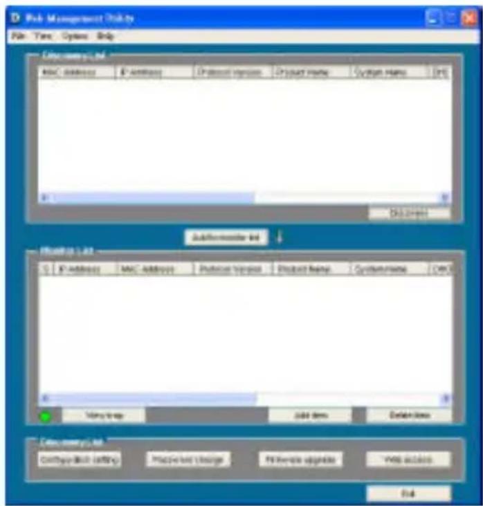
Figure 8. Web Management Utility
The Web Management Utility is divided into four parts, Discovery List, Monitor List, Device Setting, and Toolbar function, for detailed instructions, follow the section below.
Discovery List
This is the list where you can discover all the Web management devices in the entire network.
By pressing the “Discovery” button, you can list all the Web Management devices in the discovery list.
Double click or press the “Add to monitor list” button to select a device from the Discovery List to the Monitor List.
System word definitions in the Discovery List:
◆ MAC Address: Shows the device MAC Address.
◆ IP Address: Shows the current IP address of the device.
◆ Protocol version: Shows the version of the Utility protocol.
◆ Product Name: Shows the device product name.
◆ System Name: Shows the appointed device system name.
◆ Location: Shows where the device is located.
◆ Trap IP: Shows the IP where the Trap is to be sent.
◆ Subnet Mask: Shows the Subnet Mask set of the device.
◆ Gateway: Shows the Gateway set of the device.
Monitor List
All the Web Smart Devices in the Monitor List can be monitored. You can also receive the trap and show the status of the devices.
System word definitions in the Monitor List:
◆ S: Shows the system symbol of the Web-Smart device, represents a device system that is not alive.
◆ IP Address: Shows the current IP address of the device.
◆ MAC Address: Shows the device MAC Address.
◆ Protocol version: Shows the version of the Utility protocol.
◆ Product Name: Shows the device product name.
◆ System Name: Shows the appointed device system name.
◆ Location: Shows where the device is located.
◆ Trap IP: Shows the IP where the Trap is to be sent.
◆ Subnet Mask: Shows the Subnet Mask set of the device.
View Trap
The Trap function can receive the events that happen on the Web Management Switch in the Monitor List.
There is a light indicator behind the “View Trap” button. When the light is green, it means that there is no trap transmitted, and when it is red, it means that a new trap has been transmitted, reminding us to view the trap. (Figure 9)
Figure 9. View trap button
When the “View Trap” button is clicked, a Trap Information window will pop up. It will display the trap information including the Symbol, Time, Device IP, and the Event occurred. (Figure 10) The symbol “!” represents the trap signal. This symbol will disappear after you review and click on the event record.
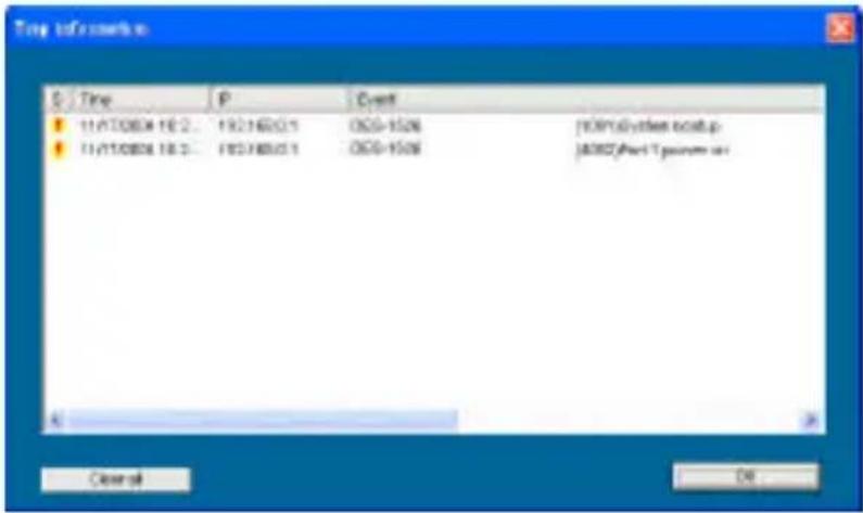
Figure 10. Trap information
Note: In order to receive Trap information, the Switch has to be configured with Trap IP and Trap Events in the Web browser. These settings are available in the Trap Setting Menu.
Add Item
To add a device to the Monitor List manually, enter the IP Address of the device that you want to monitor.
Delete Item
To delete the device in the Monitor List.
Device Setting
You can set the device by using the function key in the Device Setting Dialog box.
Configuration Setting
In this Configuration Setting, you can set the IP Address, Subnet Mask, Gateway, Set Trap to (Trap IP Address), System name, Location, and DHCP setting.
In factory default, the IP address of the DES-1526 will be atomically assigned from a DHCP server (DHCP enabled). If your network has no DHCP server, the DES-1526 will fail to get an IP address, and the DES-1526 will be assigned the default IP address of 192.168.0.1 with a netmask of 255.255.255.0.
Select the device in the Discovery list or Monitor List and press this button; then the Configuration Setting window will pop up (Figure 11). After filling in the data that you want to change, you
must fill in the password and press the “Set” button to process the data change immediately.
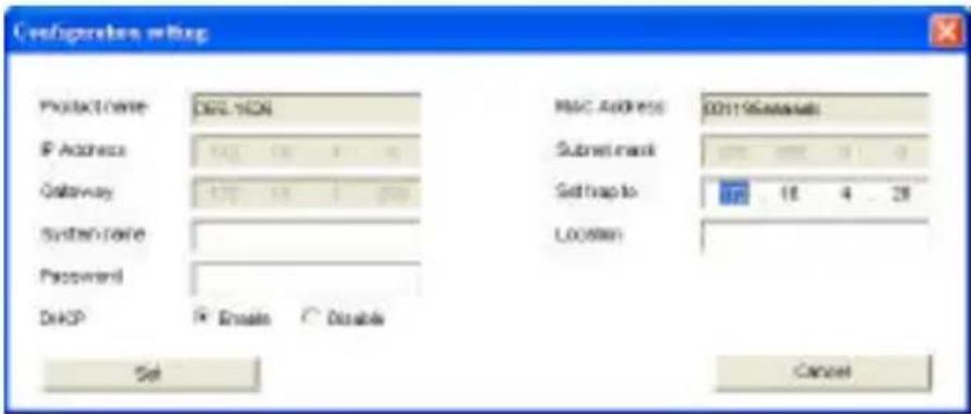
Figure 11. Configuration Setting
Password Change
You can use this when you need to change the password. Fill in the required passwords in the dialog boxes and press the “Set” button to process the password change immediately.
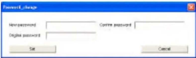
Figure 12. Password Change
Firmware Upgrade
When the device has a new function, there will be a new firmware to update the device; use this function to upgrade the firmware.
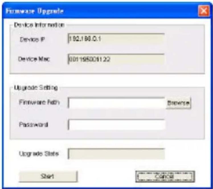
Figure 13. Firmware upgrade
Web Access
Double click the device in the Monitor List or select a device in the Monitor List and press the “Web Access” button to access the device in a Web browser.
Toolbar
The toolbar in the Web Management Utility has four main tabs: File, View, Options, and Help.
File TAB
In the “File TAB”, there is Monitor Save, Monitor Save As, Monitor Load, and Exit.
Monitor Save: To record the settings of the Monitor List to the default settings so that when you open the Web Management Utility the next time, it will automatically load the default recorded setting.
Monitor Save As: To record the setting of the Monitor List to an appointed filename and file path.
Monitor Load: To manually load the setting file of the Monitor List.
Exit: To exit the Web Management Utility.
View TAB
In the “View TAB”, there are the view log and clear log functions, the view log function will help you display trap settings.
View Log: To display the event of the Web Management Utility and the device.
Clear Log: To clear the log.
Option TAB
In the “Option TAB”, there is the Refresh Time function. This function helps you to refresh the time for monitoring the device. Choose 15 secs, 30 secs, 1 min, 2 min, and 5 min to select the time for monitoring.
Help TAB
In the “Help TAB”, there is the About function; it displays the version of the Web Management Utility.
Configuring the Switch
The DES-1526 has a Web GUI interface for smart switch configuration. The Switch can be configured through the Web browser. A network administrator can manage, control, and monitor the Switch from the local LAN. This section indicates how to configure the Switch to enable its smart functions including: Port Settings VLAN Settings, Trunk Settings, Port Mirroring, SNMP Settings, PoE Settings, Status, Statistics, System Settings, Trap Settings, Password Settings, Backup Settings, and Reset Settings.
Login
Before you configure this device, note that when the Web Smart Switch is configured through an Ethernet connection, make sure the manager PC must be set on same the IP network. For example, when the default IP address of the Web Smart Switch is 192.168.0.1, then the manager PC should be set at 192.168.0.x (where x is a number between 2 and 254), and the default subnet mask is 255.255.255.0.
Open the Web browser program and Enter IP address http://192.168.0.1 (the factory-default IP address setting) to the address location.
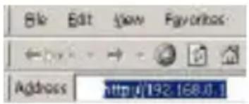
Figure 14.
Or through the Web Management Utility, you do not need to remember the IP Address, select the device shown in the Monitor List of the Web Management Utility to settle the device on the Web browser.
When the following dialog page appears, enter the default password "admin" and press Login to enter the main configuration window.
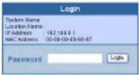
Figure 15
After entering the password, the main page appears, and the screen will display the device status.
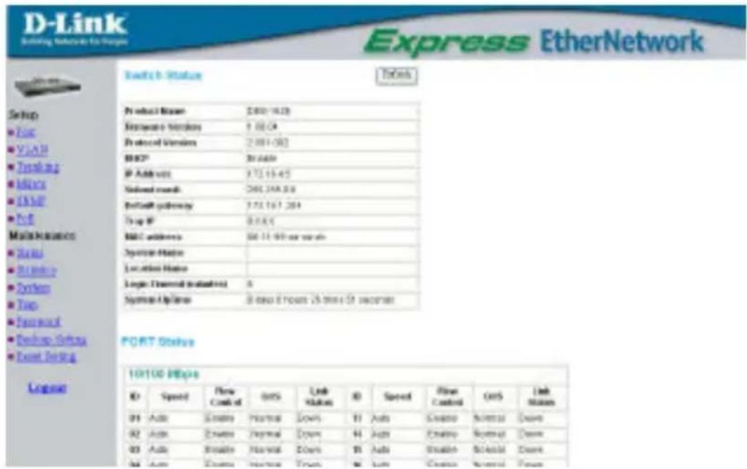
Figure 16
Setup Menu
When the main page appears, the Setup menu is on the left side of the screen (Figure 17). Click on the setup item that you want to configure. There are eleven options: Port Settings, VLAN Settings, Trunk Settings, Mirror Settings, SNMP Settings, PoE Settings, Device Status, Statistics, System Settings, Trap Settings, Password Settings, Backup Settings, and Reset Settings as shown in the Main Menu screen.
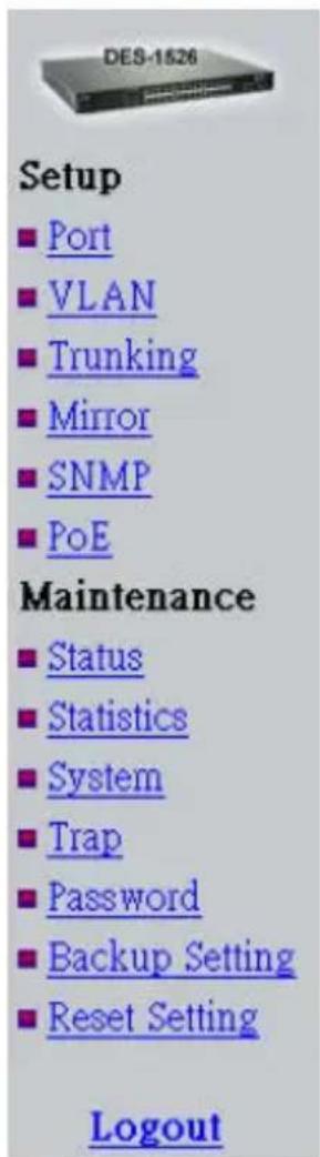
Figure 17. Setup menu
Configuring Setup Setting
There are six items, including Port Settings, VLAN Settings, Trunk Settings, Mirror Settings, SNMP Settings, and PoE Settings in Setup menu.
Port Settings
In the Port Settings menu (Figure 18), this page will display each port's status. Press the ID parameter to set each port's Speed, Flow Control, QoS and Link Status. When you need to renew the posted information, press the “Refresh” button.
The Link Status in the screen will display the connection speed and duplex mode; otherwise this dialog box will display down when the port is disconnected.
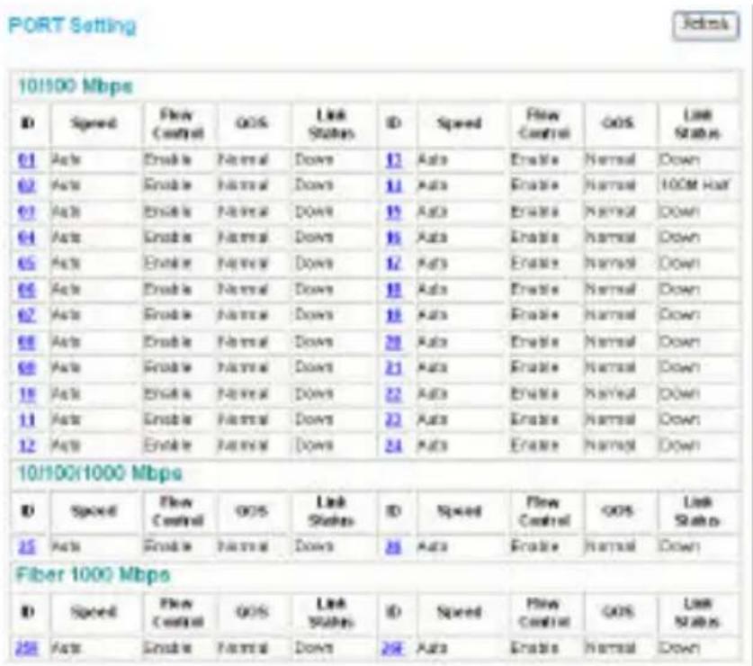
Figure 18. Port Configuration
To change the port setting, click on the ID parameter to enter the selected port to configure its Speed/Disable and Flow control.
PORT Settings
Please be aware that speed must set as some as link partner. Otherwise, packet loss or link error might occur.
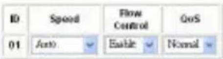

Figure 19. Port Settings.
Speed/Disable:
This setting has six modes—100M Full, 100M Half, 10M Full, 10M Half, Auto, and Disable—for speed or port disable selections.
Flow Control:
This setting determines whether or not the Switch will be handling flow control. Set FlowCtrl to Enable for avoiding data transfer overflow. If it is set to Disable, there is either no flow control or other hardware/software management.
When the 10/100M port is set to full-duplex mode, then the flow control will be automatically set to disable; and if the 10/100M port is set to half-duplex mode, the flow control will be automatically set to enable.
QoS:
In some ports that need to have a high priority to manage the data transfer, QoS should be changed. Set the port's QoS to high to determine the port will always transfer their data first.
802.1Q VLAN Settings (Virtual Local Area Network)
A VLAN is a collection of switch ports that make up a single broadcast domain. You can configure a VLAN for a single switch, or for multiple switches. When you create a VLAN, you can control traffic flow and ease the administration of moves, adds, and changes on the network, by eliminating the need to change physical cabling.
On VLAN settings, there are two main settings, VID Table Setting and Port VLAN Setting.
VID: Select the VID group that you set.
When you select VID Table Setting, press “Add new VID” to create new VID group, from port 01 \~ port 26 (26F), select Untag Port, Tag Port, or Not Member for each port. To save the VID group, press the “Apply” button. To remove the selected VID group, select the VID group and press “Remove the VID” button. To modify the VID group setting, select the VID group and change the setting, and press the “Apply” button to save the settings.
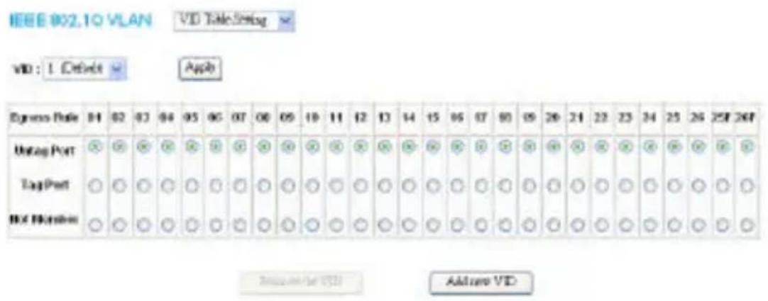
Figure 20. VLAN Settings
When you select Port VLAN setting, fill in each port's PVID value between 1 and 4094.
IEEE 802.1Q VLAN
Port VID Setting

| Port | PVID | Port | PVID | Port | PVID | Port | PVID |
| 01 | 1 | 02 | 1 | 03 | 1 | 04 | 1 |
| 05 | 1 | 06 | 1 | 07 | 1 | 08 | 1 |
| 09 | 1 | 10 | 1 | 11 | 1 | 12 | 1 |
| 13 | 1 | 14 | 1 | 15 | 1 | 16 | 1 |
| 17 | 1 | 18 | 1 | 19 | 1 | 20 | 1 |
| 21 | 1 | 22 | 1 | 23 | 1 | 24 | 1 |
| 25 | 1 | 26 | 1 | 25F | 1 | 26F | 1 |

Figure 21.
Trunk Setting
The Trunk function enables you to cascade two or more devices with larger bandwidths.
There are four Trunking groups to be set; and there are default ports in each member. Checked “Enable” to use the trunk function, select the ports in each member to be trunk, and click “Apply” to activate the selected trunk group.
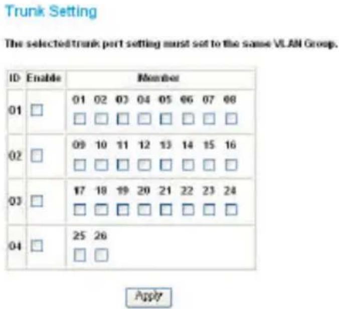
Figure 22. Trunk Settings
Be sure that the selected trunk setting port is connected to the device with a same VLAN group.
Mirror Setting
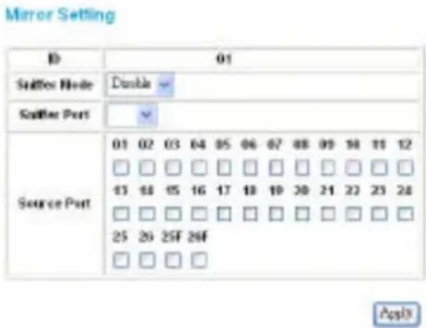
Port Mirroring is a method of monitoring network traffic that forwards a copy of each incoming and/or outgoing packet from one port of a network switch to another port where the packet can be studied. It enables the manager to keep close track of switch performance and alter it if necessary.
Configuring the port mirroring by assigning a source port from which to copy all packets and a sniffer port where those packets will be sent.
The selections of the sniffer mode are as follows:
TX (transmit) mode: This mode will duplicate the data transmitted from the source port and forward it to the sniffer port.
RX (receive) mode: This mode will duplicate the data sent to the source and forward it to the sniffer port.
Both (transmit and receive) mode: This mode will duplicate both the data transmitted from and data sent to the source port, and then it will forward the data to the sniffer port.
SNMP Setting
Simple Network Management Protocol (SNMP) is an OSI Layer 7 (Application Layer) designed specifically for managing and monitoring network devices. SNMP enables network management stations to read and modify the settings of gateways, routers, switches, and other network devices. Use SNMP to configure system features for proper operation, monitor performance and detect potential problems in the Switch, switch group, or network.
Managed devices that support SNMP include software (referred to as an agent), which runs locally on the device. A defined set of variables (managed objects) is maintained by the SNMP agent and used to manage the device. These objects are defined in a Management Information Base (MIB), which provides a standard presentation of the information controlled by the on-board SNMP agent. SNMP defines both the format of the MIB specifications and the protocol used to access this information over the network.
The DES-1526 supports the SNMP versions 1. In SNMP v.1, user authentication is accomplished using 'community strings', which function like passwords. The remote user SNMP application and the Switch SNMP must use the same community string. SNMP packets from any station that has not been authenticated are ignored (dropped).
The default community strings for the Switch used for SNMP v.1 management access are:
public - Allows authorized management stations to retrieve MIB objects.
private - Allows authorized management stations to retrieve and modify MIB objects.
Traps
Traps are messages that alert network personnel of events that occur on the Switch. The events can be as serious as a reboot (someone accidentally turned OFF the Switch), or less serious like a port status change. The Switch generates traps and sends them to the trap recipient (or network manager). Typical traps include trap messages for Device boot up, Authentication Failure, Port status change, and Abnormal transmit/receive data packet error.
MIBs
Management and counter information are stored by the Midspan in the Management Information Base (MIB). The DES-1526 uses the standard MIB-II Management Information Base module and Power over Ethernet MIB (RFC3621). Consequently, values for MIB objects can be retrieved from any SNMP-based network management software. In addition, the DES-1526 also supports its own proprietary enterprise MIB as an extended Management Information Base. The proprietary MIB may also be retrieved by specifying the MIB Object Identifier. MIB values can be either read-only or read-write.
Enabled / Disabled: To enable or disable the SNMP function on the Switch.
SNMP Community / Trap: To configure the SNMP Community or SNMP Trap configuration.
Configure SNMP Community:
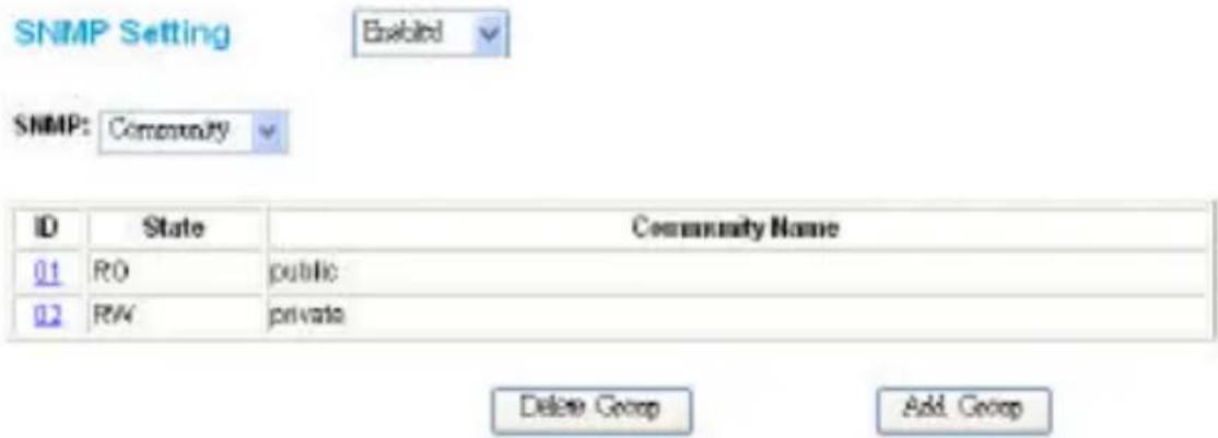
Figure 24. SNMP Community Setting
Add Group: To add a SNMP Community group, press the “Add Group” button. The Add SNMP Community configuration window will pop up. Fill in the community name and assign the community enable read_only or read_write. Press the “Apply” button to execute the setting.
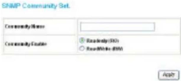
Figure 25. Add SNMP Community group
Delete Group: To delete previously defined SNMP Community group, press the “Delete Group” button. The Delete SNMP Community configuration window will pop up; check the delete dialog box. Press “Apply” to delete the selected SNMP Community Group.
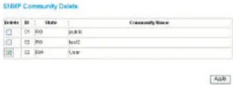
Figure 26. Delete SNMP Community group
Modify Group: To modify a previously defined SNMP Community group, click on the ID parameter to enter to the selected SNMP Community Group to configure its community name and community enable. Press “Apply” to save change of the SNMP Community Group.
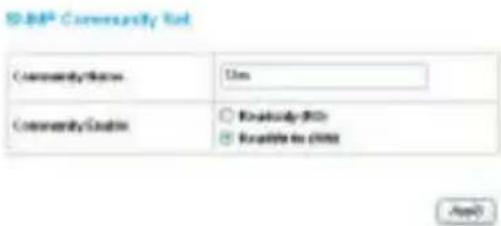
Figure 27. Modify SNMP Community group
Configure SNMP Trap:
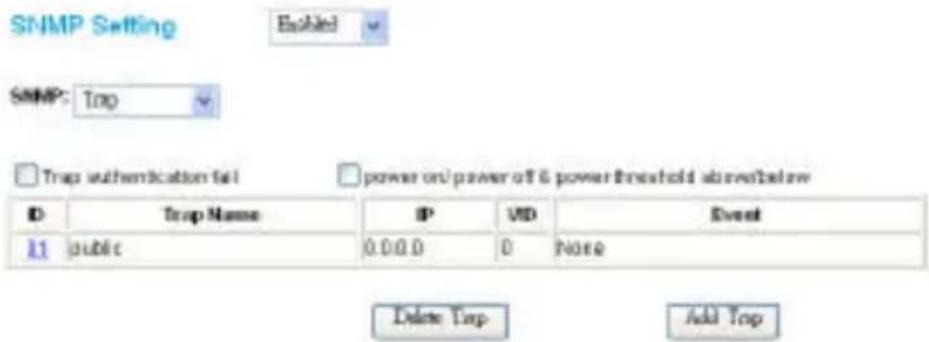
Figure 28. Configure SNMP Trap Setting
Trap authentication fail: When checked, the dialog box of the Trap authentication fail. A trap when authentication fails, the Switch will trap the authentication failure even to the SNMP host.
Power on/power off & threshold above/below: When checked the dialog box of the power on/power off & power threshold above/below. A trap when the PoE port's power turned on/turned off; or radio of the system power supply larger than or smaller than the System power Threshold setting.
Add Trap: To create a recipient of SNMP traps generated by the Switch's SNMP agent, press the “Add Trap” button, and the SNMP Trap Set window will pop up. You can fill in the community name and trap IP address of the remote management station that will serve as the SNMP host for the Switch and check the events selection to enabled selected event traps.
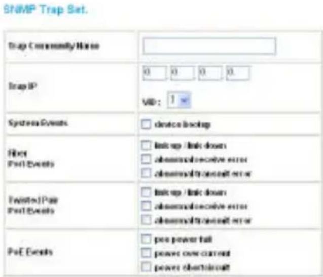
Figure 29. Add SNMP Trap
System Events: Monitoring the Switch status.
Device bootup: A trap when the Switch Bootup was successful.
Fiber Port Events: Monitoring the Fiber port status.
Link Up/Link Down: A trap when there is linking status in the fiber port.
Abnormal* Receive Error: A trap when there is a receive data error in the fiber port.
Abnormal* Transmit Error: Atrap when there is a transmit data error in the fiber port.
Twisted Pair Port Events: Monitoring the twisted pair port status.
Link Up/Link Down: A trap when there is linking statusin the twisted pair port.
Abnormal* Receive Error: A trap when there is a receive data error in the twisted pair port.
Abnormal* Transmit Error: A trap when there is a transmit data error in the twisted pair port.
Abnormal\*: 50 error packet count within 10 seconds.
PoE Events: Monitoring the PoE ports status.
PoE Power fail: A trap when the port's power source fails or the PD64012 fails.
Power over current: A trap when the PoE port's power is over current.
Power short circuit: A trap when the PoE port's power circuit was short.
Delete Trap: To delete previously defined SNMP Trap, press the “Delete Trap” button. The Delete SNMP Trap Delete configuration window will pop up; check the delete dialog box. Press “Apply” to delete the selected SNMP Trap setting.
SNMP Trap Delete.
| Delete | ID | Trap Name | IP | VID | Event |
| 01 | public | 0.0.0.0 | 0 | None | |
| 02 | public | 172.16.4.28 | 1 | 01, F2, F3, F4, T1, T2, T3, p1, p2, p3, p4, p5. |

Figure 30. Delete SNMP Trap
Modify Trap: To modify a previously defined SNMP Trap, click on the ID parameter to enter to the selected SNMP Trap to configure its community name, IP address, and events. Press “Apply” to save changes of the SNMP Trap.
SNMP Trap Set.
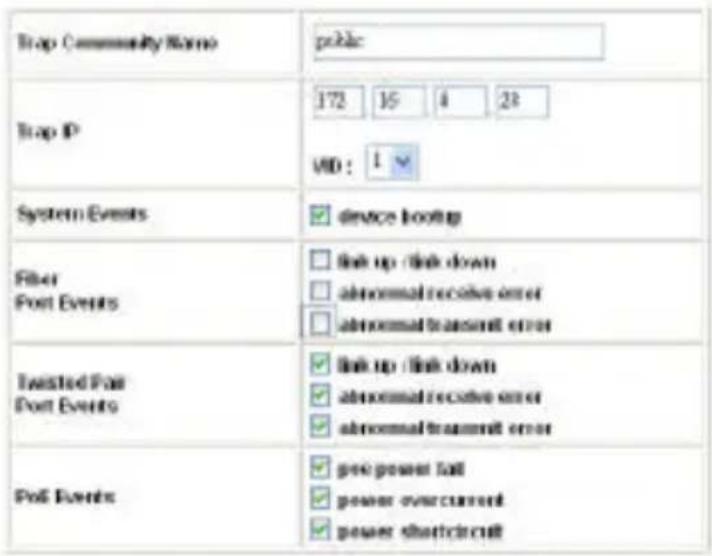
Figure 31. Modify SNMP Trap
PoE Setting
When you click on the PoE Setting, the PoE Status will appear on the screen. It will display the PoE status including, Port Enable, Power limit, Power (W), Voltage(V), Current (mA), Classification, Port status, System Budget Power, Support Total Power, Remainder Power, and The ratio of system power supply.
Note: The PoE Status information of Power current, Power Voltage, and Current is the power usage information of the connected PD; please “Refresh” to renew the information.
| POE Port Status | |||||||
| ID | Power Enable | power limit | Power (W) | Voltage (V) | Consumal (mA) | Classification | Status |
| 01 | Enable | Auto | 0.00 | 0.00 | 0.00 | + | Normal |
| 02 | Enable | Auto | 0.00 | 0.00 | 0.00 | + | Normal |
| 03 | Enable | Auto | 0.00 | 0.00 | 0.00 | + | Normal |
| 04 | Enable | Auto | 0.00 | 0.00 | 0.00 | + | Normal |
| 05 | Enable | Auto | 0.00 | 0.00 | 0.00 | + | Normal |
| 06 | Enable | Auto | 0.00 | 0.00 | 0.00 | + | Normal |
| 07 | Enable | Auto | 0.00 | 0.00 | 0.00 | + | Normal |
| 08 | Enable | Auto | 0.00 | 0.00 | 0.00 | + | Normal |
| 09 | Enable | Auto | 0.00 | 0.00 | 0.00 | + | Normal |
| 10 | Enable | Auto | 0.00 | 0.00 | 0.00 | + | Normal |
| 11 | Enable | Auto | 0.00 | 0.00 | 0.00 | + | Normal |
| 12 | Enable | Auto | 0.00 | 0.00 | 0.00 | + | Normal |
| 13 | Enable | Auto | 0.00 | 0.00 | 0.00 | + | Normal |
| 14 | Enable | Auto | 0.00 | 0.00 | 0.00 | + | Normal |
| 15 | Enable | Auto | 0.00 | 0.00 | 0.00 | ||
| 16 | Enable | Auto | 0.00 | 0.00 | - | ||
Figure 32. PoE Status
POE Port Status:
Selected “POE Port Status” to configure the PoE Port setting.
To configure the settings, click on the ID parameter to enter the selected port.
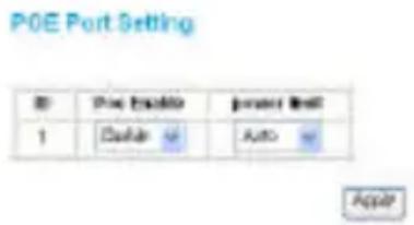
Figure 33. PoE Port Setting
Poe Enable: Select to enable or disable the PoE function.
Power limit: This function allows you to manually set the port power current limitation to be given to the PD. To protect the DWL-P1526 and the connected device, the power limit function will disable the PoE function of the port when the power is overloaded. Select “<5W”, “<10W”, “<14W” and “Auto” for the power limit. “Auto” will follow the classification from the PD power current.
POE System Setting:
Selected “POE System Setting” to configure the PoE System setting.
POE System Setting
POB System.fing
Systempower Threshold
图 C-40
APPL?
Figure 34. PoE System Setting
System power Threshold: When the radio of the system power supply is large than or smaller than the System power Threshold setting, the Switch will send trap event to the Management Station.
Note: When there is a system power shortage with the PD, the Switch will enforce the PoE port priority management. The lower port number will have the higher priority than the higher port number, Port 1 > Port 2 > ... > Port 24.
Device Status
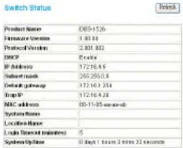
Click on the “Status” button to display the device status on this screen. It will display the System Status, Port Status, VLAN Status, Trunk Status, Mirror Status, and PoE Status.
Press “Refresh” when you need to renew the posted information.
PORT Status
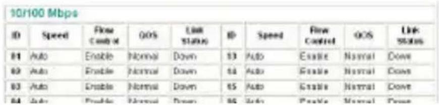
Figure 35. System Status
Statistics
The Statistics Menu screen will display the status of each port packet count.
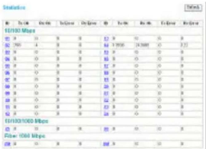
Figure 36. Statistic
For detailed packet information, click on the ID parameter as Figure 26.
| Port | 10 | ||
| Tx | |||
| Bytes | 4340847 | ||
| UnicastParks | 6142 | DropParks | D |
| RikicarsParks | 7402 | PasserParks | D |
| BroadcastParks | 13 | TransNetDisc | D |
| DeferredConcertal | 562 | Collision | 115 |
| LabtCollection | 0 | Successive Collision | D |
| RX | |||
| Bytes | 67253948 | ||
| UnicastParks | 135775 | DropParks | D |
| RikicarsParks | 58398 | PasserParks | D |
| BroadcastParks | 67641 | SuccessiveDisc | D |
| UnderSizeParks | 0 | OverSizeParks | 48 |
| Adderies | 0 | Recravants | 78 |
| PCSEmors | 0 | SBCCharges | 152755 |
| 64 Bps@Parks | 425 | 90 to 127 Bps@Parks | 114143 |
| 128 to 255Bps@Parks | 45458 | 258 to 515Bps@Parks | 52478 |
| 512 to 1023 Bps@Parks | 19708 | 1024to 1522 Bps@Parks | 18608 |
Figure 37. Port Statistics
System Setting
The System Setting includes the System name, Location name, Login Timeout, IP Address, Subnet Mask, and Gateway. Through the Web Management Utility, you can easily recognize the device by using the System Name and the Location Name.
The Login Timeout is to set the idle time-out for security issues, When there is no action when running the Web Smart Utility and the time is up, you must re-login to Web Smart Utility before you set the Utility.
Fill in the IP address, Subnet mask, and Gateway for the device or enable DHCP get IP address from DHCP server.
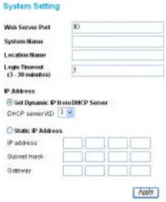
Figure 38.
Trap Setting
The Trap Setting enables the device to monitor the Trap through the Web Management Utility. Set the Trap IP Address of the manager where the trap is to be sent.
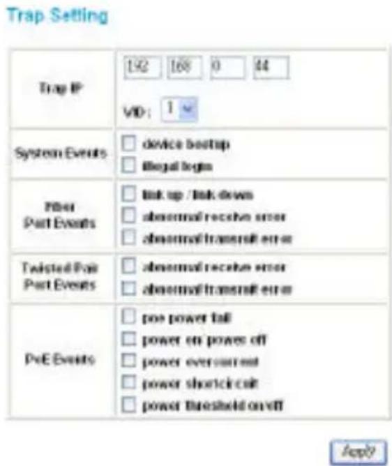
Figure 39. Trap Setting
System Events: Monitoring the system's trap.
Device Bootup: A trap when booting up the system.
Illegal Login: A trap when there is an incorrect password login. It will record the IP that attempted to login.
Fiber Port Events: Monitoring the Fiber port status.
Link Up/Link Down: A trap when there is linking status in the fiber port.
Abnormal* Receive Error: A trap when there is a receive data error in the fiber port.
Abnormal* Transmit Error: A trap when there is a transmit data error in the fiber port.
Twisted Pair Port Events: Monitoring the twisted pair port status.
Abnormal* Receive Error: A trap when there is a receive data error in the twisted pair port.
Abnormal* Transmit Error: A trap when there is a transmit data error in the twisted pair port.
Abnormal*: 50 error packet count within 10 seconds.
PoE Events: Monitoring the PoE ports status.
PoE Power fail: A trap when the port's power source fails or the PD64012 fails.
Power on/Power off: A trap when the PoE port's power is on and off.
Power over current: A trap when the PoE port's power is over current.
Power short circuit: A trap when the PoE port's power circuit was short.
Power threshold on/off: A trap when the radio of the system power supply larger than or smaller than the System power Threshold setting.
Set Password
Password is the invaluable tool for the manager to secure the Web Management Switch. You can use this function to change the password.
If you forget the password, press the “Reset” button in the rear panel of the Switch. The current setting includes VLAN, Port Setting... etc. will be lost and the Switch will be restored to the default setting.
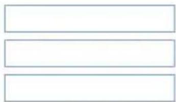
Password Setting
The maximum length is 20 and is case-sensitive.
Old Password
New Password
Re-type New Password
natural_image
Three horizontal rectangular frames with no text or symbols
Figure 40.Set Password
Backup Setting
The backup tools help you to backup the current setting of the Switch. Once you need to backup the setting, press the “Backup” button to save the setting.
To restore a current setting file to the device, you must specify the backup file and press the “Restore” button to process the setting of the recorded file.
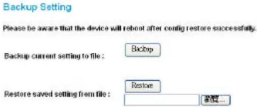
Figure 41. Backup Setting
Note: When restoring a recorded file, the current password will not be erased.
Reset Setting
The Factory Reset button helps you to reset the device back to the default setting from the factory. Be aware that the entire configuration will be reset, the IP address of the device will be retrieved from DHCP server (factory default is DHCP enabled) or the default IP address of 192.168.0.1 will be used when the device fails to retrieve the IP address from DHCP server.
Factory Reset
Please be aware that all configuration will reset to default value.
Factory Reset
Figure 42. Reset Setting
Logout
When you select this function, the Web configuration will log out and return to first Login page.
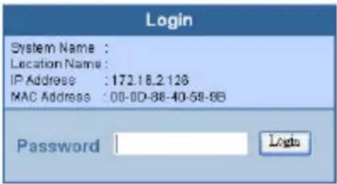
Figure 43. Logout
TECHNICAL SPECIFICATIONS
| General | |
| Standards | IEEE 802.3 10BASE-T EthernetIEEE 802.3u 100BASE-TX Fast EthernetIEEE 802.3ab 1000BASE-T Gigabit EthernetIEEE 802.3x Full Duplex Flow ControlIEEE 802.3af compliant |
| Protocol CSMA/CD | |
| Data Transfer Rate | Ethernet: 10Mbps (half-duplex), 20Mbps (full-duplex)Fast Ethernet: 100Mbps (half-duplex), 200Mbps (full-duplex)Gigabit Ethernet: 2000Mbps (full-duplex) |
| Topology Star | |
| Network Cables | 10BASET: 2-pair UTP Cat. 3, 4, 5; up to 100m100BASE-TX: 2-pair UTP Cat. 5; up to 100m1000BASE-T: 4-pair UTP Cat. 5; up to 100mPoE: 4-pair UTP Cat. 5; up to 100m |
| Number of Ports | 24 x 100BASE-TX PoE Ethernet ports2 x 1000BASE-T Gigabit Ethernet ports2 x mini-GBIC ports (shared) |
| Power over Ethernet | |
| Standard IEEE | 802.3af |
| Power current | Up to 15.4W per portMaximum 170W per device |
| PD Classification | Auto PD classification identify |
| PoE pin assignment | Power(+): pin 3 & pin 6 in RJ-45Power(-): pin 1 & pin 2 in RJ-45 |
| Safety protection | Over current protectCircuit shortage protect |
| Physical and Environmental | |
| AC inputs | 100-240V AC, 50-60 Hz internal universal power supply |
| Power Consumption | 9Watts (max. no PD Device connected)180Watts (max. with 11 x 15.4 w PoE Device connected) |
| Temperature | Operating: 0° ~ 40°C (32° ~ 104°F), Storage: -10° ~ 70°C (14° ~ 158°F) |
| Humidity | Operating: 10% ~ 90%, Storage: 5% ~ 90% |
| Dimensions | 440 x 310 x 44 mm |
| EMI: | FCC Class A, CE Mark Class A, VCCI Class A |
| Safety: | cUL(UL60950), CB(IEC60950) |
| Performance | |
| Transmits Method: | Store-and-forward |
| Filtering Address Table: | 4K entries per device |
| Packet Filtering/Forwarding Rate: | 10Mbps Ethernet: 14,880/pps100Mbps Fast Ethernet: 148,800/pps1000Mbps Gigabit Ethernet: 1,488,000/pps |
| MAC Address Learning: | Automatic update |
| Transmits Method: | Store-and-forward |
| RAM Buffer: | 768K bytes per device |
Warranty and Registration Information
(All countries and regions excluding USA and Europe)
IF YOU PURCHASED A D-LINK PRODUCT IN THE UNITED STATES, SOME STATES DO NOT ALLOW THE LIMITATION OR EXCLUSION OF LIABILITY FOR INCIDENTAL OR CONSEQUENTIAL DAMAGES, SO THE ABOVE LIMITATION MAY NOT APPLY TO YOU.
Limited Warranty
Hardware:
D-Link warrants each of its hardware products to be free from defects in workmanship and materials under normal use and service for a period commencing on the date of purchase from D-Link or its Authorized Reseller and extending for the length of time stipulated by the Authorized Reseller or D-Link Branch Office nearest to the place of purchase.
This Warranty applies on the condition that the product Registration Card is filled out and returned to a D-Link office within ninety (90) days of purchase. A list of D-Link offices is provided at the back of this manual, together with a copy of the Registration Card.
If the product proves defective within the applicable warranty period, D-Link will provide repair or replacement of the product. D-Link shall have the sole discretion whether to repair or replace, and replacement product may be new or reconditioned. Replacement product shall be of equivalent or better specifications, relative to the defective product, but need not be identical. Any product or part repaired by D-Link pursuant to this warranty shall have a warranty period of not less than 90 days, from date of such repair, irrespective of any earlier expiration of original warranty period. When D-Link provides replacement, then the defective product becomes the property of D-Link.
Warranty service may be obtained by contacting a D-Link office within the applicable warranty period, and requesting a Return Material Authorization (RMA) number. If a Registration Card for the product in question has not been returned to D-Link, then a proof of purchase (such as a copy of the dated purchase invoice) must be provided. If Purchaser's circumstances require special handling of warranty correction, then at the time of requesting RMA number, Purchaser may also propose special procedure as may be suitable to the case.
After an RMA number is issued, the defective product must be packaged securely in the original or other suitable shipping package to ensure that it will not be damaged in transit, and the RMA number must be prominently marked on the outside of the package. The package must be mailed or otherwise shipped to D-Link with all costs of mailing/shipping/insurance prepaid. D-Link shall never be responsible for any software, firmware, information, or memory data of Purchaser contained in, stored on, or integrated with any product returned to D-Link pursuant to this warranty.
Any package returned to D-Link without an RMA number will be rejected and shipped back to Purchaser at Purchaser's expense, and D-Link reserves the right in such a case to levy a reasonable handling charge in addition mailing or shipping costs.
Software:
Warranty service for software products may be obtained by contacting a D-Link office within the applicable warranty period. A list of D-Link offices is provided at the back of this manual, together with a copy of the Registration Card. If a Registration Card for the product in question has not been returned to a D-Link office, then a proof of purchase (such as a copy of the dated purchase invoice) must be provided when requesting warranty service. The term "purchase" in this software warranty refers to the purchase transaction and resulting license to use such software.
D-Link warrants that its software products will perform in substantial conformance with the applicable product documentation provided by D-Link with such software product, for a period of ninety (90) days from the date of purchase from D-Link or its Authorized Reseller. D-Link warrants the magnetic media, on which D-Link provides its software product, against failure during the same warranty period. This warranty applies to purchased software, and to replacement software provided by D-Link pursuant to this warranty, but shall not apply to any update or replacement which may be provided for download via the Internet, or to any update which may otherwise be provided free of charge.
D-Link's sole obligation under this software warranty shall be to replace any defective software product with product which substantially conforms to D-Link's applicable product documentation. Purchaser assumes responsibility for the selection of appropriate application and system/platform software and associated reference materials. D-Link makes no warranty that its software products will work in combination with any hardware, or any application or system/platform software product provided by any third party, excepting only such products as are expressly represented, in D-Link's applicable product documentation as being compatible. D-Link's obligation under this warranty shall be a reasonable effort to provide compatibility, but D-Link shall have no obligation to provide compatibility when there is fault in the third-party hardware or software. D-Link makes no warranty that operation of its software products will be uninterrupted or absolutely error-free, and no warranty that all defects in the software product, within or without the scope of D-Link's applicable product documentation, will be corrected.
Subject to the terms and conditions set forth herein, D-Link Systems, Inc. ("D-Link") provides this Limited Warranty:
- Only to the person or entity that originally purchased the product from D-Link or its authorized reseller or distributor, and
- Only for products purchased and delivered within the fifty states of the United States, the District of Columbia, U.S. Possessions or Protectorates, U.S. Military Installations, or addresses with an APO or FPO.
Limited Warranty: D-Link warrants that the hardware portion of the D-Link product described below ("Hardware") will be free from material defects in workmanship and materials under normal use from the date of original retail purchase of the product, for the period set forth below ("Warranty Period"), except as otherwise stated herein.
• Hardware (excluding power supplies and fans): Five (5) Years
• Power supplies and fans: One (1) Year
• Spare parts and spare kits: Ninety (90) days
The customer's sole and exclusive remedy and the entire liability of D-Link and its suppliers under this Limited Warranty will be, at D-Link's option, to repair or replace the defective Hardware during the Warranty Period at no charge to the original owner or to refund the actual purchase price paid. Any repair or replacement will be rendered by D-Link at an Authorized D-Link Service Office. The replacement hardware need not be new or have an identical make, model or part. D-Link may, at its option, replace the defective Hardware or any part thereof with any reconditioned product that D-Link reasonably determines is substantially equivalent (or superior) in all material respects to the defective Hardware. Repaired or replacement hardware will be warranted for the remainder of the original Warranty Period or ninety (90) days, whichever is longer, and is subject to the same limitations and exclusions. If a material defect is incapable of correction, or if D-Link determines that it is not practical to repair or replace the defective Hardware, the actual price paid by the original purchaser for the defective Hardware will be refunded by D-Link upon return to D-Link of the defective Hardware. All Hardware or part thereof that is replaced by D-Link, or for which the purchase price is refunded, shall become the property of D-Link upon replacement or refund.
Limited Software Warranty: D-Link warrants that the software portion of the product ("Software") will substantially conform to DLink's then current functional specifications for the Software, as set forth in the applicable documentation, from the date of original retail purchase of the Software for a period of ninety (90) days ("Software Warranty Period"), provided that the Software is properly installed on approved hardware and operated as contemplated in its documentation. D-Link further warrants that, during the Software Warranty Period, the magnetic media on which D-Link delivers the Software will be free of physical defects. The customer's sole and exclusive remedy and the entire liability of D-Link and its suppliers under this Limited Warranty will be, at D-Link's option, to replace the non-conforming Software (or defective media) with software that substantially conforms to DLink's
functional specifications for the Software or to refund the portion of the actual purchase price paid that is attributable to the Software. Except as otherwise agreed by D-Link in writing, the replacement Software is provided only to the original licensee, and is subject to the terms and conditions of the license granted by D-Link for the Software. Replacement Software will be warranted for the remainder of the original Warranty Period and is subject to the same limitations and exclusions. If a material non-conformance is incapable of correction, or if D-Link determines in its sole discretion that it is not practical to replace the non-conforming Software, the price paid by the original licensee for the non-conforming Software will be refunded by D-Link; provided that the non-conforming Software (and all copies thereof) is first returned to D-Link. The license granted respecting any Software for which a refund is given automatically terminates.
Non-Applicability of Warranty: The Limited Warranty provided hereunder for Hardware and Software portions of D-Link's products will not be applied to and does not cover any refurbished product and any product purchased through the inventory clearance or liquidation sale or other sales in which D-Link, the sellers, or the liquidators expressly disclaim their warranty obligation pertaining to the product and in that case, the product is being sold "As-Is" without any warranty whatsoever including, without limitation, the Limited Warranty as described herein, notwithstanding anything stated herein to the contrary.
Submitting A Claim: The customer shall return the product to the original purchase point based on its return policy. In case the return policy period has expired and the product is within warranty, the customer shall submit a claim to D-Link as outlined below:
- The customer must submit with the product as part of the claim a written description of the Hardware defect or Software nonconformance in sufficient detail to allow D-Link to confirm the same, along with proof of purchase of the product (such as a copy of the dated purchase invoice for the product) if the product is not registered.
- The customer must obtain a Case ID Number from D-Link Technical Support at 1-877-453-5465, who will attempt to assist the customer in resolving any suspected defects with the product. If the product is considered defective, the customer must obtain a Return Material Authorization ("RMA") number by completing the RMA form and entering the assigned Case ID Number at https://rma.dlink.com/.
- After an RMA number is issued, the defective product must be packaged securely in the original or other suitable shipping package to ensure that it will not be damaged in transit, and the RMA number must be prominently marked on the outside of the package. Do not include any manuals or accessories in the shipping package. D-Link will only replace the defective portion of the product and will not ship back any accessories.
- The customer is responsible for all in-bound shipping charges to D-Link. No Cash on Delivery ("COD") is allowed. Products sent COD will either be rejected by D-Link or become the property of D-Link. Products shall be fully insured by the customer and shipped to D-Link Systems, Inc., 17595 Mt. Herrmann, Fountain Valley, CA 92708. D-Link will not be held responsible for any packages that are lost in transit to D-Link. The repaired or replaced packages will be shipped to the customer via UPS Ground or any common carrier selected by D-Link. Return shipping charges shall be prepaid by D-Link if you use
an address in the United States, otherwise we will ship the product to you freight collect. Expedited shipping is available upon request and provided shipping charges are prepaid by the customer.
D-Link may reject or return any product that is not packaged and shipped in strict compliance with the foregoing requirements, or for which an RMA number is not visible from the outside of the package. The product owner agrees to pay D-Link's reasonable handling and return shipping charges for any product that is not packaged and shipped in accordance with the foregoing requirements, or that is determined by D-Link not to be defective or non-conforming.
What Is Not Covered: The Limited Warranty provided herein by D-Link does not cover: Products that, in D-Link's judgment, have been subjected to abuse, accident, alteration, modification, tampering, negligence, misuse, faulty installation, lack of reasonable care, repair or service in any way that is not contemplated in the documentation for the product, or if the model or serial number has been altered, tampered with, defaced or removed; Initial installation, installation and removal of the product for repair, and shipping costs; Operational adjustments covered in the operating manual for the product, and normal maintenance; Damage that occurs in shipment, due to act of God, failures due to power surge, and cosmetic damage; Any hardware, software, firmware or other products or services provided by anyone other than D-Link; and Products that have been purchased from inventory clearance or liquidation sales or other sales in which D-Link, the sellers, or the liquidators expressly disclaim their warranty obligation pertaining to the product. While necessary maintenance or repairs on your Product can be performed by any company, we recommend that you use only an Authorized D-Link Service Office. Improper or incorrectly performed maintenance or repair voids this Limited Warranty.
Disclaimer of Other Warranties: EXCEPT FOR THE LIMITED WARRANTY SPECIFIED HEREIN, THE PRODUCT IS PROVIDED "AS-IS" WITHOUT ANY WARRANTY OF ANY KIND WHATSOEVER INCLUDING, WITHOUT LIMITATION, ANY WARRANTY OF MERCHANTABILITY, FITNESS FOR A PARTICULAR PURPOSE AND NON-INFRINGEMENT. IF ANY IMPLIED WARRANTY CANNOT BE DISCLAIMED IN ANY TERRITORY WHERE A PRODUCT IS SOLD, THE DURATION OF SUCH IMPLIED WARRANTY SHALL BE LIMITED TO THE DURATION OF THE APPLICABLE WARRANTY PERIOD SET FORTH ABOVE. EXCEPT AS EXPRESSLY COVERED UNDER THE LIMITED WARRANTY PROVIDED HEREIN, THE ENTIRE RISK AS TO THE QUALITY, SELECTION AND PERFORMANCE OF THE PRODUCT IS WITH THE PURCHASER OF THE PRODUCT.
Limitation of Liability: TO THE MAXIMUM EXTENT PERMITTED BY LAW, D-LINK IS NOT LIABLE UNDER ANY CONTRACT, NEGLIGENCE, STRICT LIABILITY OR OTHER LEGAL OR EQUITABLE THEORY FOR ANY LOSS OF USE OF THE PRODUCT, INCONVENIENCE OR DAMAGES OF ANY CHARACTER, WHETHER DIRECT, SPECIAL, INCIDENTAL OR CONSEQUENTIAL (INCLUDING, BUT NOT LIMITED TO, DAMAGES FOR LOSS OF GOODWILL, LOSS OF REVENUE OR PROFIT, WORK STOPPAGE, COMPUTER FAILURE OR MALFUNCTION, FAILURE OF OTHER EQUIPMENT OR COMPUTER PROGRAMS TO WHICH D-LINK'S PRODUCT IS CONNECTED WITH, LOSS OF INFORMATION OR DATA CONTAINED IN, STORED ON, OR INTEGRATED WITH ANY PRODUCT RETURNED TO D-LINK FOR WARRANTY SERVICE) RESULTING FROM THE USE OF THE PRODUCT, RELATING TO WARRANTY SERVICE, OR ARISING OUT OF ANY BREACH OF THIS LIMITED WARRANTY, EVEN IF D-LINK HAS BEEN ADVISED OF THE POSSIBILITY OF SUCH DAMAGES. THE SOLE REMEDY FOR A BREACH OF THE FOREGOING LIMITED WARRANTY IS REPAIR, REPLACEMENT OR REFUND OF THE DEFECTIVE OR NON-CONFORMING PRODUCT. THE MAXIMUM LIABILITY OF D-LINK UNDER THIS WARRANTY IS LIMITED TO THE PURCHASE PRICE OF THE PRODUCT COVERED BY THE WARRANTY. THE FOREGOING EXPRESS WRITTEN
WARRANTIES AND REMEDIES ARE EXCLUSIVE AND ARE IN LIEU OF ANY OTHER WARRANTIES OR REMEDIES, EXPRESS, IMPLIED OR STATUTORY.
Governing Law. This Limited Warranty shall be governed by the laws of the State of California. Some states do not allow exclusion or limitation of incidental or consequential damages, or limitations on how long an implied warranty lasts, so the foregoing limitations and exclusions may not apply. This Limited Warranty provides specific legal rights and you may also have other rights which vary from state to state.
Trademarks: D-Link is a registered trademark of D-Link Systems, Inc. Other trademarks or registered trademarks are the property of their respective owners.
Copyright Statement: No part of this publication or documentation accompanying this product may be reproduced in any form or by any means or used to make any derivative such as translation, transformation, or adaptation without permission from D-Link Corporation/D-Link Systems, Inc., as stipulated by the United States Copyright Act of 1976 and any amendments thereto. Contents are subject to change without prior notice. Copyright 2004 by D-Link Corporation/D-Link Systems, Inc. All rights reserved.
CE Mark Warning: This is a Class A product. In a residential environment, this product may cause radio interference, in which case the user may be required to take adequate measures.
FCC Statement: This equipment has been tested and found to comply with the limits for a Class A digital device, pursuant to part 15 of the FCC Rules. These limits are designed to provide reasonable protection against harmful interference in a commercial installation. This equipment generates, uses, and can radiate radio frequency energy and, if not installed and used in accordance with the instructions, may cause harmful interference to radio communication. However, there is no guarantee that interference will not occur in a particular installation. Operation of this equipment in a residential environment is likely to cause harmful interference to radio or television reception. If this equipment does cause harmful interference to radio or television reception, which can be determined by turning the equipment off and on, the user is encouraged to try to correct the interference by one or more of the following measures:
• Reorient or relocate the receiving antenna.
- Increase the separation between the equipment and receiver.
- Connect the equipment into an outlet on a circuit different from that to which the receiver is connected.
- Consult the dealer or an experienced radio/TV technician for help.
For detailed warranty information applicable to products purchased outside the United States, please contact the corresponding local D-Link office.
Product Registration
Register online your D-Link product at http://support.dlink.com/register/
Product registration is entirely voluntary and failure to complete or return this form will not diminish your warranty rights.
- Trademarks
Copyright 2002 D-Link Corporation. Contents subject to change without prior notice. D-Link is a registered trademark of D-Link Corporation/ D-Link Systems Inc. All other trademarks belong to their respective proprietors.
- Copyright statement
No part of this publication may be reproduced in any form or by any means or used to make an derivative such as translation, transformation, or adaptation without permission from DLink Corporation/ DLink Systems Inc as stipulated by the United States Copyright Act of 1976.
CE EMI class A warning
This is a Class A product. In a domestic environment, this product may cause radio interference, in which case the user may be required to take adequate measures.
D-Link Europe Limited Product Warranty General Terms
The Limited Product Warranty set forth below is given by D-LINK (Europe) Ltd. (herein referred to as "D-LINK"). This Limited Product Warranty is only effective upon presentation of the proof of purchase. Upon further request by D-LINK, this warranty card has to be presented, too.
EXCEPT AS EXPRESSLY SET FORTH IN THIS LIMITED WARRANTY, D-LINK MAKES NO OTHER WARRANTIES, EXPRESS OR IMPLIED, INCLUDING ANY IMPLIED WARRANTIES OF MERCHANTABILITY AND FITNESS FOR A PARTICULAR PURPOSE. D-LINK EXPRESSLY DISCLAIMS ALL WARRANTIES NOT STATED IN THIS LIMITED WARRANTY. ANY IMPLIED WARRANTIES THAT MAY BE IMPOSED BY LAW ARE LIMITED IN DURATION TO THE LIMITED WARRANTY PERIOD. SOME STATES OR COUNTRIES DO NOT ALLOW A LIMITATION ON HOW LONG AN IMPLIED WARRANTY LASTS OR THE EXCLUSION OR LIMITATION OF INCIDENTAL OR CONSEQUENTIAL DAMAGES FOR CONSUMER PRODUCTS. IN SUCH STATES OR COUNTRIES, SOME EXCLUSIONS OR LIMITATIONS OF THIS LIMITED WARRANTY MAY NOT APPLY TO YOU. THIS LIMITED WARRANTY GIVES YOU SPECIFIC LEGAL RIGHTS. YOU MAY ALSO HAVE OTHER RIGHTS THAT MAY VARY FROM STATE TO STATE OR FROM COUNTRY TO COUNTRY. YOU ARE ADVISED TO CONSULT APPLICABLE STATE OR COUNTRY LAWS FOR
A FULL DETERMINATION OF YOUR RIGHTS.
This limited warranty applies to D-LINK branded hardware products (collectively referred to in this limited warranty as "D-LINK Hardware Products") sold by from DLINK (Europe) Ltd., its worldwide subsidiaries, affiliates, authorized resellers, or country distributors (collectively referred to in this limited warranty as "D-LINK") with this limited warranty. The Term "D-LINK Hardware Product" is limited to the hardware components and all its internal components including firmware. The term "D-LINK Hardware Product" DOES NOT include any software applications or programs.
Geographical Scope of the Limited Product Warranty
This Limited Product Warranty is applicable in all European Countries as listed in the addendum “European Countries for D-LINK Limited Product Warranty”. The term “European Countries” in this D-LINK Limited Product Warranty only include the countries as listed in this addendum. The Limited Product Warranty will be honored in any country where DLINK or its authorized service providers offer warranty service subject to the terms and conditions set forth in this Limited Product Warranty. However, warranty service availability and response times may vary from country to country and may also be subject to registration requirements.
Limitation of Product Warranty
D-LINK warrants that the products described below under normal use are free from material defects in materials and workmanship during the Limited Product Warranty Period set forth below ("Limited Product Warranty Period"), if the product is used and serviced in accordance with the user manual and other documentation provided to the purchaser at the time of purchase (or as amended from time to time). D-LINK does not warrant that the products will operate uninterrupted or error-free or that all deficiencies, errors, defects or non-conformities will be corrected.
This warranty shall not apply to problems resulting from: (a) unauthorised alterations or attachments; (b) negligence, abuse or misuse, including failure to operate the product in accordance with specifications or interface requirements; (c) improper handling; (d) failure of goods or services not obtained from D-LINK or not subject to a then-effective D-LINK warranty or maintenance agreement; (e) improper use or storage; or (f) fire, water, acts of God or other catastrophic events. This warranty shall also not apply to any particular product if any D-LINK serial number has been removed or defaced in any way.
D-LINK IS NOT RESPONSIBLE FOR DAMAGE THAT OCCURS AS A RESULT OF YOUR FAILURE TO FOLLOW THE INSTRUCTIONS FOR THE D-LINK HARDWARE PRODUCT.
Limited Product Warranty Period
The Limited Product Warranty Period starts on the date of purchase from D-LINK. Your dated sales or delivery receipt, showing the date of purchase of the product, is your proof of the purchase date. You may be required to provide proof of purchase as a condition of receiving warranty service. You are entitled to warranty service according to the terms and conditions of this document if a repair to your D-LINK branded hardware is required within the Limited Product Warranty Period.
This Limited Product Warranty extends only to the original end-user purchaser of this D-LINK Hardware Product and is not transferable to anyone who obtains ownership of the D-LINK Hardware Product from the original end-user purchaser.
| Product Type Product Warranty Period | |
| Managed Switches (i.e. switches with built in SNMP agent)(including modules and management software) | Five (5) years |
| All other products Two (2) years | |
| Spare parts (i.e. External Power Adapters, Fans) | One (1) year |
The warranty periods listed above are effective in respect of all D-LINK products sold in European Countries by D-LINK or one of its authorized resellers or distributors from 1st of January 2004. All products sold in European Countries by DLINK or one of its authorized resellers or distributors before 1st January 2004 carry 5 years warranty, except power supplies, fans and accessories that are provided with 2 year warranty.
The warranty period stated in this card supersedes and replaces the warranty period as stated in the user's manual or in the purchase contract for the relevant products. For the avoidance of doubt, if you have purchased the relevant D-LINK product as a consumer your statutory rights remain unaffected.
Performance of the Limited Product Warranty
If a product defect occurs, D-LINK's sole obligation shall be to repair or replace any defective product free of charge to the original purchaser provided it is returned to an Authorized D-LINK Service Center during the warranty period. Such repair or replacement will be rendered by D-LINK at an Authorized D-LINK Service Center. All component parts or hardware products removed under this limited warranty become the property of D-LINK. The replacement part or product takes on the remaining limited warranty status of the removed part or product. The replacement product need not be new or of an identical make, model or part; D-LINK may in its discretion replace the defective product (or any part thereof) with any reconditioned equivalent (or superior) product in all material respects to the defective product. Proof of purchase may be required by D-LINK.
Warrantor
D-Link (Europe) Ltd.
4th Floor, Merit House
Edgware Road
Colindale
London NW9 5 AB
United Kingdom
Telephone: +44-020-8731-5555
Facsimile: +44-020-8731-5511
www.dlink.co.uk
D-Link Europe Limited Produktgarantie Allgemeine Bedingungen
4th Floor, Merit House
Edgware Road
Colindale
London NW9 5 AB
4th Floor, Merit House
Edgware Road
Colindale
London NW9 5 AB
Royaume-Uni
Tél : +44-020-8731-5555
Fax : +44-020-8731-5511
www.dlink.co.uk
4th Floor, Merit House
Edgware Road
Colindale
London NW9 5 AB
United Kingdom
4th Floor, Merit House
Edgware Road
Colindale
Londra NW9 5 AB
Regno Unito
Telefono: +44-020-8731-5555
- Manual
- FCC Warning
- CE Mark Warning
- Warnung!
- Table of Contents......iii
- About This Manual....1
- Introduction....2
- Unpacking and Installation....8
- Identifying External Components....14
- Purpose
- Terms/Usage
- Fast Ethernet Technology
- Gigabit Ethernet Technology
- Switching Technology
- VLAN (Virtual Local Area Network)
- Power over Ethernet (PoE)
- Features
- Unpacking
- Installation
- Installing the Switch on a Desktop
- Installing the Switch on a Rack
- Connecting Network Cables
- AC Power
- IDENTIFYING EXTERNAL COMPONENTS
- Front Panel
- LED Indicator:
- 10/100Mbps PoE Ports (Port 1\~24):
- 1000BASE-T Gigabit Ethernet Ports (Port 25\~26):
- mini-GBIC Ports (Port 25F\~26F):
- Reset:
- Rear Panel
- AC Power Connector:
- System LEDs
- Gigabit Ethernet Port Status LEDs
- Installing the Web Management Utility
- Discovery List
- System word definitions in the Discovery List:
- Monitor List
- System word definitions in the Monitor List:
- View Trap
- Add Item
- Delete Item
- Device Setting
- Configuration Setting
- Password Change
- Firmware Upgrade
- Web Access
- Toolbar
- File TAB
- View TAB
- Option TAB
- Help TAB
- Configuring the Switch
- Login
- Setup Menu
- Configuring Setup Setting
- Port Settings
- Speed/Disable:
- Flow Control:
- QoS:
- 802.1Q VLAN Settings (Virtual Local Area Network)
- Trunk Setting
- Mirror Setting
- SNMP Setting
- Traps
- MIBs
- Configure SNMP Community:
- Configure SNMP Trap:
- Abnormal\*: 50 error packet count within 10 seconds.
- PoE Setting
- POE Port Status:
- POE System Setting:
- Device Status
- Statistics
- System Setting
- Trap Setting
- Set Password
- Password Setting
- Backup Setting
- Reset Setting
- Logout
- Warranty and Registration Information
- (All countries and regions excluding USA and Europe)
- Limited Warranty
- Hardware:
- Software:
- D-Link Europe Limited Product Warranty General Terms
- Geographical Scope of the Limited Product Warranty
- Limitation of Product Warranty
- Limited Product Warranty Period
- Performance of the Limited Product Warranty
- Warrantor
- D-Link Europe Limited Produktgarantie Allgemeine Bedingungen
Brand : D-LINK
Model : DES-1526
Category : Network switch