
AM 1621X - Mixer PHONIC - Free user manual and instructions
Find the device manual for free AM 1621X PHONIC in PDF.


| Product Type | Mixing Console |
| Model | AM 1621X |
| Brand | Phonic |
| Number of Input Channels | 18 (16 mono + 2 stereo) |
| Mic Preamps | 18 (16 mono + 2 stereo with mic preamp) |
| Equalization | 3-band EQ with swept mid (100 Hz-8 kHz) on mono channels; 4-band EQ (High Mid, Low Mid) on stereo channels |
| Low Cut Filter | 75 Hz, 18 dB/octave on each mono channel |
| Aux Sends | 4 (AUX 1 & 2 with XLR and 1/4" outputs, EFX 1 & 2) |
| Stereo Returns | 2 (1/4" TS) |
| Built-in Effects | 16 programs (32/40-bit DSP) with parameter control and tap delay |
| Phantom Power | +48V DC (global switch) |
| Main Outputs | Stereo L/R (XLR and 1/4" TS), Mono/Subwoofer (XLR and 1/4" TS) |
| Other Outputs | Control Room/Phones (1/4"), Rec Out (RCA and mini stereo) |
| Inputs | Balanced Mic/Line (XLR/1/4" combo), Stereo Line (1/4" TS), Tape In (RCA and mini stereo) |
| Dimensions (W x H x D) | 774 x 112 x 437.2 mm (30.5" x 4.4" x 17.2") |
| Net Weight | 10.5 kg (23.1 lbs) |
| Power Supply | Built-in switching, 100-240 VAC, 50/60 Hz, 50W |
| Frequency Response | 20 Hz - 60 kHz (+0/-1 dB); 20 Hz - 100 kHz (+0/-3 dB) |
| THD | <0.005% (any output, 1 kHz @ +14 dBu) |
| Signal-to-Noise Ratio | >90 dB |
| Microphone E.I.N. | <-129.5 dBm (150 ohms terminated, max gain) |
| Crosstalk | <-90 dB (1 kHz @ 0 dBu, channel to main) |
| Faders | 60 mm (channel, aux, effects, mono, main L/R) |
| Level Meter | 12-segment stereo |
| Accessories | Optional rack-mount kit (ER8IM) for AM821X only; foot switch jack for effects |
Frequently Asked Questions - AM 1621X PHONIC
User questions about AM 1621X PHONIC
0 question about this device. Answer the ones you know or ask your own.
Ask a new question about this device
Download the instructions for your Mixer in PDF format for free! Find your manual AM 1621X - PHONIC and take your electronic device back in hand. On this page are published all the documents necessary for the use of your device. AM 1621X by PHONIC.
USER MANUAL AM 1621X PHONIC
AM2421X
AM 821X
AM 1221X
AM 1621X
AM 2421X
User's Manual
Manual del Usuario
AM 821X AM 1221X AM 1621X AM 2421X
MIXING CONSOLE CONSOLA DE MEZCLA
ENGLISH ......I
ESPAÑOL ......II
USER'S MANUAL
CONTENTS
INTRODUCTION 1
FEATURES 1
BASIC SETUP 1
GETTING STARTED 1
CHANNEL SETUP 1
MAKING CONNECTIONS 2
CONNECTING PANEL 2
REAR PANEL 3
MAIN MIXING PANEL 3
CONTROLS AND SETTINGS 3
REAR PANEL 3
CHANNEL CONTROLS 4
DIGITAL EFFECT ENGINE 5
TAPE IN SECTION 6
MASTER CONTROL SECTION 6
SPECIFICATIONS 8
APPENDIX
DIGITAL EFFECT TABLE 1
APPLICATIONS 2
DIMENSIONS 4
BLOCK DIAGRAMS 5
Phonic preserves the right to improve or alter any information within this document without prior notice
IMPORTANT SAFETY INSTRUCTIONS
The apparatus shall not be exposed to dripping or splashing and that no objects filled with liquids, such as vases, shall be placed on the apparatus. The MAINS plug is used as the disconnect device, the disconnect device shall remain readily operable.
Warning: the user shall not place this apparatus in the confined area during the operation so that the mains switch can be easily accessible.
-
Read these instructions before operating this apparatus.
-
K eep these instructions for future reference.
-
H eed all warnings to ensure safe operation.
-
Follow all instructions provided in this document.
-
Do not use this apparatus near water or in locations where condensation may occur.
-
Clean only with dry cloth. Do not use aerosol or liquid cleaners. Unplug this apparatus before cleaning.
-
Do not block any of the ventilation openings. Install in accordance with the manufacturer's instructions.
-
Do not install near any heat sources such as radiators, heat registers, stoves, or other apparatus (including amplifiers) that produce heat.
-
Do not defeat the safety purpose of the polarized or grounding-type plug. A polarized plug has two blades with one wider than the other. A grounding type plug has two blades and a third grounding prong. The wide blade or the third prong is provided for your safety. If the provided plug does not fit into your outlet, consult an electrician for replacement of the obsolete outlet.
-
Protect the power cord from being walked on or pinched particularly at plug, convenience receptacles, and the point where they exit from the apparatus.
-
Only use attachments/accessories specified by the manufacturer.
-
Use only with a cart, stand, tripod, bracket, or table specified by the manufacturer, or sold with the apparatus. When a cart is used, use caution when moving the cart/apparatus combination to avoid injury from tip-over.
-
Unplug this apparatus during lighting storms or when unused for long periods of time.
-
Refer all servicing to qualified service personnel. Servicing is required when the apparatus has been damaged in any way, such as power-supply cord or plug is damaged, liquid has been spilled or objects have fallen into the apparatus, the apparatus has been exposed to rain or moisture, does not operate normally, or has been dropped.

CAUTION: TO REDUCE THE RISK OF ELECTRIC SHOCK, DO NOT REMOVE COVER (OR BACK) NO USER SERVICEABLE PARTS INSIDE REFER SERVICING TO QUALIFIED PERSONNEL

The lightning flash with arrowhead symbol, within an equilateral triangle, is intended to alert the user to the presence of uninsulated "dangerous voltage" within the product's enclosure that may be of sufficient magnitude to constitute a risk of electric shock to persons.

The exclamation point within an equilateral triangle is intended to alert the user to the presence of important operating and maintenance (servicing) instructions in the literature accompanying the appliance.
WARNING: To reduce the risk of fire electric shock, do not expose this apparatus to rain or moisture.
CAUTION: Use of controls or adjustments or performance of procedures other than thosepecified may result in hazardous radiation exposure.




CAUTION: Use of controls or adjustments or performance of procedures other than thosepecified may result in hazardous radiation exposure.
INTRODUCTION
Thank you for choosing one of Phonic's many quality compact mixers. The AM mixing consoles - designed by the same talented engineers that have created a variety of mixers fantastic in style and performance in the past - display similar proficiency that previous Phonic products have shown; with more than a few refinements, of course.
With a total of 4 models in the 'AM 21X' series, the AM821X, AM1221X, AM1621X and AM2421X, all with varying inputs yet displaying the same efficacy, you have no doubt purchased a mixer that will not only prove ideal for your application, but will outlast many others.
We know how eager you are to get started - wanting to get the mixer out and hook it all up is probably your number one priority right now - but before you do, we strongly urge you to take a look through this manual. Inside, you will find important facts and figures on the set up, use and applications of your brand new mixer. If you do happen to be one of the many people who flatly refuse to read user manuals, then we just urge you to at least glance at the Instant Setup section. After reading through the manual, please store it in a place that is easy for you to find, because chances are there is something you missed the first time around.
FEATURES
• Audiophile-Quality & ultra low noise
- Mono channels with inserts and phantom power
• 2 stereo channels with 4-band EQ
- 10, 14, 18, 26 mic preamps on the AM821X, AM1221X, AM1621X and AM2421X
- 3-band EQ with swept mid-range plus low cut on each mono channel
- 18dB/oct, 75Hz low cut filter on each mono channels
- 4 aux sends, aux 1 & 2 with XLR and 1/4" output jacks
- 2 stereo aux returns, each with effect to monitor
- Pad on mono channels to handle difficult signals
- Main Stereo and Mono output with XLR and 1/4" jacks
- Mono output with variable low pass filter for subwoofer speaker
- Tape input can be routed to aux 1 and aux 2
- Handy mini-stereo I/O for MD, MP3 player/recorder
- Built-in switching power supply with universal connector, 100-240VAC, 50/60Hz
- Optional rack-mounting kit for AM821X only, model name ER8IM
- 32/40-bit digital multi-effect processor with 16 programs with parameter control and tap delay
BASIC SETUP
GETTING STARTED
- Ensure all power is turned off on the AM Mixer. To totally ensure this, the AC cable should not be connected to the unit.
- All faders and level controls should be set at the lowest level and all channels switched off to ensure no sound is inadvertently sent through the outputs when the device is switched on. All levels should be altered to acceptable degrees after the device is turned on.
- Plug all necessary instruments and equipment into the device's various inputs as required. This may include line signal devices, as well as microphones and/or guitars, keyboards, etc.
- Turn the gain of the selected channel to a degree that allows the audio level shown in the level meter to sit around 0 dB, ensuring it never reaches 7 dB..
- Plug the supplied AC cable into the AC inlet on the back of the device ensuring the local voltage level is identical to that required on your device.
- Plug the supplied AC cable into a power outlet of a suitable voltage.
- Turn the power switch on.
CHANNEL SETUP
- To ensure the correct audio levels of each input channel is selected, every channel should first be switched off and all faders set to 0.
- Choose the channel that you wish to set the level of and ensure that channel has a signal sent to it similar to the signal that will be sent when in common use. For example, if the channel is using a microphone, then you should speak or sing at the same level the performer normally would during a performance. If a guitar is plugged into that channel, then the guitar should also be used as it normally would be.
- Press the PFL button of the channel, allowing you to see the audio properties in the level meter.
- Turn the gain of the selected channel to a degree that allows the audio level shown in the level meter to sit around 0 dB, ensuring it never reaches 7 dB.
- This channel is now ready to be used; you can stop making the audio signal and disengage the PFL button.
- You should now select the next channel to set and go back to follow steps 1 through 6.
MAKING CONNECTIONS CONNECTING PANEL
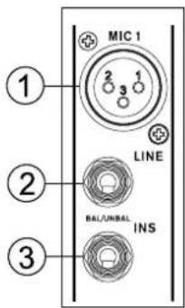
1. XLR Jacks
These jacks accept XLR inputs for balanced signals. They can be used in conjunction with microphones such as professional condenser, dynamic or ribbon microphones - with standard XLR male connectors. With low noise preamplifiers, these inputs serve for crystal clear sound replication.
NB. When using an unbalanced microphone, please ensure phantom power is switched off. However, when using condenser microphones the phantom power should be activated.
2. Line In Jacks
These balanced inputs accept 1/4" TRS and 1/4" TS line inputs for the addition of various music instruments – such as keyboards, drum machines, electric guitars, as well as a variety of other electric instruments.
3. Insert Jacks
The primary use for these TRS phone jacks is for the addition of external devices, such as dynamic processors or equalizers, to the corresponding mono input channel. This will require a Y cord that can send and receive signals of the mixer to and from an external processor. The tip of the TRS jack will send the signal from the input channel, and the ring will return the signal back to the mixer (the sleeve is the grounding).
4. Stereo Channels
The two stereo channels on the mixers include XLR Mic inputs and 1/4" TS phone jacks. They can be used in conjunction with various stereo devices, such as synthesizers and keyboards. Also, by connecting a mono signal to the left phone jack, the mixer automatically doubles the signal over to the right channel. This is known as jack normalizing.
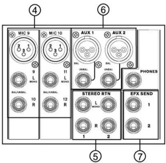
5. Stereo Returns
The 1/4" TS Stereo Return inputs are for the return of audio to the mixer, processed by an external signal processor. If really needed, they can also be used as additional stereo inputs. The feed from these inputs can be adjusted using the Stereo Return controls on the face of the mixer. When connecting a monaural device to the AUX Return inputs, simply plug a 1/4" phone jack into the left (mono) input, and the signal will appear in the right as well.
6. Auxiliary (AUX) 1 and 2 Outputs
These balanced XLR jacks and unbalanced 1/4" TS phone jacks are the final output of line-level signal fed from the corresponding auxiliary send mixing buses, and are best suited for use with external effect processors or stage monitors. Feeding the output from the Auxiliary outs to an amplifier - and possibly an equalizer - and then to a floor monitor speaker allows artists to monitor their own instruments or vocals whilst performing.
These 1/4" TS outputs are the final output from the EFX send mixing bus. This feed may be used to connect to an external digital effect processor or even to an amplifier and speakers, depending on your desired settings.
REAR PANEL
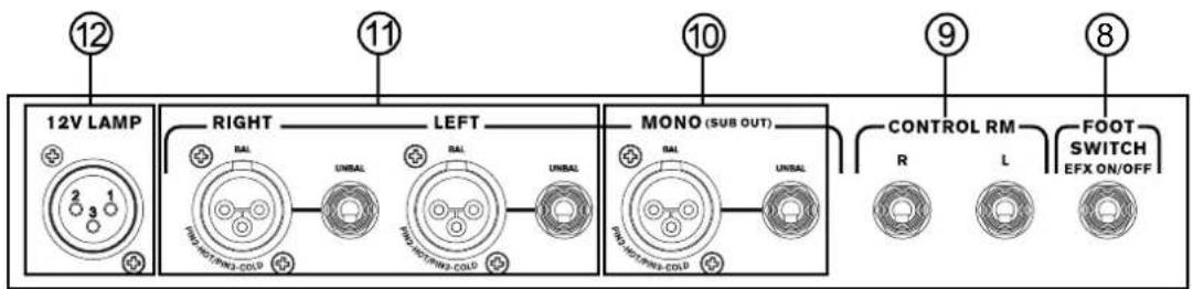
8. Foot Switch Jacks
This port is for the inclusion of a foot switch (non-latchable), used to remotely adjust properties of the built-in Digital Effects Engine. Using a footswitch with this jack will allow users to mute and un-mute the Digital Effects.
9. Control Room / Phones
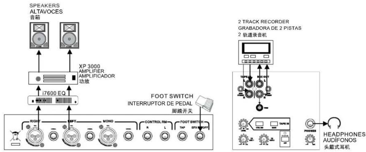
These two 1/4" Phone Jack outputs feed the signal altered by the Control Room level control on the face of the mixer. This output has extensive use, as it can be used to feed the signal from the mixer to an active monitor, for the monitoring of the audio signal from within a booth, among many other possible uses.
10. Mono / Subwoofer Output
This male XLR and 1/4" TS output feeds a monaural signal of the Main L-R signals combined, as adjusted by the accompanying level control. This is ideal for use with a mono sound system, or for the addition of a subwoofer to your set of speakers, adding more punch to low frequency sounds.
11. Main Outputs
These outputs will output the final stereo line level signal sent from the main mixing bus. The primary purpose of the two male XLR jacks and 1/4" phone jacks is to send the main left and right output signal to external devices, which may include power amplifiers (and in-turn, a pair of speakers), other mixers, as well as a wide range of other possible signal processors (equalizers, crossovers, etcetera).
12. 12V Lamp
This XLR socket allows you to attach a 12 Volt (7 Watt) gooseneck lamp, allowing better visibility in areas with poor light.
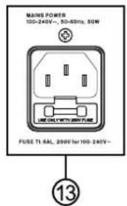
13. Power Connector
This is for the addition of an AC power cable, allowing power to be supplied to the mixer. Please use the power cable that is included with this mixer only. The Fuse holder, located below the AC Power connector, is, of course, for the mixer's fuse. If the fuse happens to blow, open the holder cover, and replace the fuse with a suitable replacement (as indicated underneath the power connector).
MAIN MIXING PANEL
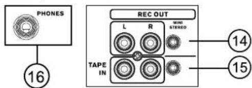
14. Tape Inputs
The first of these inputs accommodates RCA cables from such devices as tape and CD players. In addition to these inputs, however, Phonic has incorporated a mini stereo port for the inclusion of mini disc (MD), portable CD, and MP3 players (such as the Apple iPod), as well as laptop computers. The line from this feed is directed to the Tape In mixing bus, which users are able to feed to the Control Room, AUX 1 and 2 or Main L/R mixing buses.
15. Record Outputs
As with the Tape In ports, these outputs will accommodate RCA cables, able to be fed to a variety of recording devices. Also included are mini stereo ports for the addition of recording devices such as MD players and laptop computers.
16. Headphones Output
This output port is best suited for use with headphones, allowing monitoring of the mix. The audio level of this output is controlled using the Control Room / Phones control on the front panel's master section.
CONTROLS AND SETTINGS
REAR PANEL
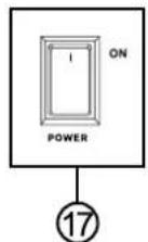
17. Power Switch
This switch is used to turn the mixer on and off. Ensure you turn all level controls down before activating.
CHANNEL CONTROLS
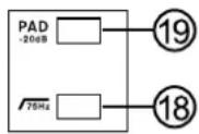
18. Low Cut Filter (75 Hz)
This button, located on all mono channels, will active a high-pass filter that reduces all frequencies below 75 Hz at 18 dB per octave, helping to remove
any unwanted ground noise or stage rumble.
19. PAD Button (Stereo Channels Only)
This button, located on channels the final 4 mono channels of all models, attenuates the input signal of the Mic or Line inputs by 20 dB. This gives a greater dynamic range to the input, allowing inputs with higher-level signals to be used without the possibility of clipping.
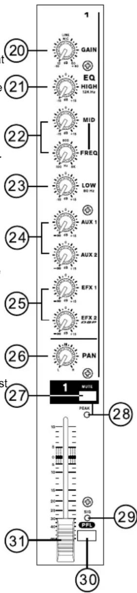
20. Gain Control
This controls the sensitivity of the input signal of the Line/Microphone input of mono channels. The gain should be adjusted to a level that allows the maximum use of the audio, while still maintaining the quality of the feed. This can be accomplished by adjusting it to a level that will allow the peak indicator occasionally illuminate or slightly lower than this.
21. High Frequency Control
This control is used to give a shelving boost or cut of ±15 dB to high frequency (12 kHz) sounds. This will adjust the amount of treble included in the audio of the channel, adding strength and crispness to sounds such as guitars, cymbals, and synthesizers.
22. Middle Frequency Control
This control is used to provide a peaking style of boost and cut to the level of middle frequency sounds at a range of ±15 dB. The mixer also provides a sweep control, allowing you to select a center frequency between 100 Hz and 8 kHz. Changing middle frequencies of an audio feed can be rather difficult when used in a professional audio mix, as it is usually more desirable to cut middle frequency sounds rather than boost them, soothing overly harsh vocal and instrument sounds in the audio.
Stereo channels differ slightly, in that they feature a High Mid and Low Mid control for adjusting Middle Frequency sounds with set frequencies of 3 kHz and 800 Hz.
23. Low Frequency Control
This control is used to give a shelving boost or cut of ±15 dB to low frequency (80 Hz) sounds. This will adjust the amount of bass included in the audio of the channel, and bring more warmth and punch to drums and bass guitars.
24. AUX Controls
These two AUX controls alters the signal level that is being sent to the auxiliary 1 and 2 mixing buses, the signal of which is suitable for connecting stage monitors, allowing artists to listen to the music that is being played, or to fed to an external effect processors.
button is engaged.
25. EFX 1 and 2
These two controls adjust the level of audio sent from the channel to the EFX 1 and 2 mixing buses. The EFX 2 signal is also sent to the built-in digital effects processor, allowing users to apply effects to the signal.
26. Pan/Balance Controls
This alternates the degree or level of audio that the left and right side of the main mix should receive. On mono channels, the PAN control will adjust the level that the left and right should receive (pan), where as on a stereo channel, adjusting the BAL control will attenuate the left or right audio signals accordingly (balance).
27. Mute Button
This button mutes the channel, effectively stopping all audio fed into the inputs from being send to the Main L/R mixing bus, as well as the AUX 1, AUX 2, EFX 1 and EFX 2 mixing buses. This indicated just below the button (labeled Peak) will be illuminated when the channel is muted.
28. Peak Indicator
This LED indicator (which doubles as a mute indicator) will illuminate when the channel hits high peaks, 6 dB before overload occurs. It is best to adjust the channel level control so as to allow the PEAK indicator to light up on regular intervals only. This will ensure a greater dynamic range of audio. This indicator also doubles as a Mute indicator, when the channel's mute
29. Sig Indicator
This LED indicator shows when the input level reaches -20 dBu, basically showing when a signal is received by the corresponding channel.
30. PFL Button
The PFL - or Pre-Fader Listen - button is pushed to allow the signal of a channel to be sent to the CTRL RM/PHONES mix (pre-fader, post-EQ), for use with either headphones or studio monitors. This allows easier setting of the input gain and tracking of audio by sound engineers. The Sig LED above the button will illuminate when PFL is activated.
31. Channel Level Control
This 60 mm fader will alter the signal level that is sent from the corresponding channel to the Main L/R mixing bus.
DIGITAL EFFECT ENGINE
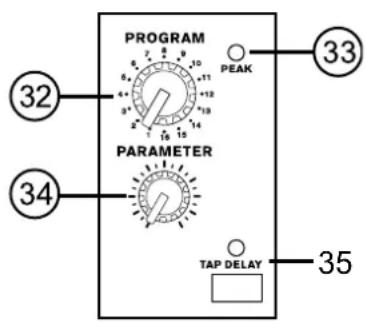
32. Program Control
This control is used to scroll through the various effects shown on the Digital Effect Display. Turning the control will automatically change the effect and apply it to the mix. For a full list of available programs and their parameters, please check the Digital Effect Table.
33. Peak Indicator
This LED indicator will illuminate when the EFX signal hits high peaks, 6 dB before overload occurs. It is best to adjust the EFX Return fader so as to allow the Peak indicator to light up on high peaks only. This will ensure a greater dynamic range for audio.
34. Parameter Control
This will adjust the appropriate parameter of the digital effect that is applied to the audio feed. Please refer to the Digital Effects Table for more information on effect parameters.
35. Tap Delay Button and Indicator
When the tap delay effect is selected, pushing this button twice will allow the processor to calculate the time between the two pushes and use this as the tap delay time. If the button is pushed multiple times, the processor will calculate the time between the last two pushes only. The LED that accompanies it will flash at the selected interval.
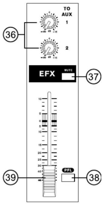
36. To Aux 1 and 2 Controls
These controls allow users to adjust the signal level that is being sent from the Effects Engine to the auxiliary 1 and 2 mixing buses, the signal of which is suitable for connecting stage monitors, allowing artists or engineers to listen to the music that is being played.
37. Mute Button
This button mutes the EFX channel, effectively stopping the signal processed by the built-in Effects Engine from being sent to the Main L/R mixing bus.
38. PFL Button
The PFL – or Pre-Fader Listen – button is pushed to allow the signal of the Effects Engine to be sent to the CTRL RM / PHONES mix. This allows easier tracking of audio by sound engineers.
39. DSP Effects Fader
This 60mm fader will alter the signal level that is sent from the Effects Engine to the Main L/R mix.
TAPE IN SECTION
flowchart
graph TD
    A["LEVEL"] --> B["④0"]
    A --> C["④1"]
    B --> D["CTRL RM"]
    B --> E["MAIN"]
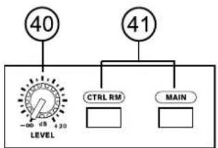
40. Level Control
This controls the level of the signal received through the Tape In mixing bus, to be sent to the Control Room / Phones and/or Main L/R mixing buses, as selected by the user.
41. CTRL RM and MAIN Buttons
These buttons allow users to send the Tape In signal to these particular mixes. Sending the Tape In signal to the Control Room mixing bus is useful in monitoring of the signal, whereas sending it to the Main L/R allows users to combine the Tape In signal with the main mix. To avoid any unwanted feedback, don't press the MAIN button down when the Record Out signal is returned to the Mixer through the Tape Inputs.
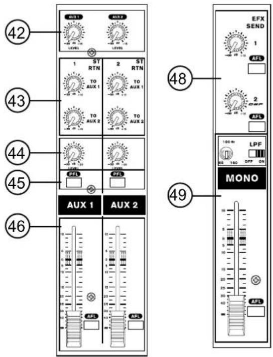
42. To AUX 1 and 2 Controls
These controls allow users to adjust the signal level of the Tape In that is sent to the auxiliary 1 and 2 mixing buses.
MASTER CONTROL SECTION
43. Stereo Return To AUX 1 and 2 Controls
These controls adjust the pre-fader level of the signal from the Stereo Return controls to the corresponding AUX mixing buses for effect-to-monitor sends.
44. Stereo Return Level Controls
These rotary control will alter the signal level that is sent from the Stereo Returns to the Main L/R mix.
45. Stereo Return PFL Buttons
The PFL - or Pre-Fader Listen - buttons are pushed to allow the Stereo Return signals to be sent to the Control Room / Phones mix (pre-fader, post-EQ), for use with either headphones or studio monitors. This allows easier tracking of audio by sound engineers.
46. AUX 1 and 2 Master Controls
These 60 mm fader will alter the signal level that is sent from the AUX 1 and 2 to their corresponding outputs. Both faders are accompanied by AFL (or After-Fader Listen) buttons, allowing users to send the post-fader signal to the Control Room / Phones mixing bus.
47. Phantom Power Button and Indicator
When this button is pushed in, +48V of Phantom Power is activated for all microphone inputs, allowing condenser microphones (well, the ones that don't use batteries) to be used on these channels. Activating Phantom Power will be accompanied by an illuminated LED above the button. Before turning Phantom Power on, turn all level controls to a minimum to avoid the possibility of a ghastly popping sound from the speakers.
NB. Phantom Power should be used in conjunction with balanced microphones. When Phantom Power is engaged, single ended (unbalanced) microphones and instruments should not be used on the Mic inputs. Phantom Power will not cause damage to most dynamic microphones, however if unsure, the microphone's user manual should be consulted.
48. EFX Send 1 and 2 Master Controls
These rotary controls adjust the final level of the EFX 1 and 2 signals (as taken from the EFX controls on each channel strip), the audio of which is sent to the corresponding EFX sends. Also accompanying the EFX Send controls is an AFL button, allowing users to send the post-fader signal to the Control Room / Phones mixing bus. The EFX 2 master control also determines the final level of the audio sent to the built-in Effects processor of the mixer.
49. Mono Channel Controls
The 60 mm faders is the final level control for the Mono mixing bus, the signal of which is sent to the Mono / Subwoofer output on the rear of the mixer. The included AFL button allows users to send the post-fader Mono signal to the Control Room mixing bus.
A Low Pass Filter has been included to cut unwanted high frequency sounds of the mono output at a rate of 12 dB per octave, for a clearer bass sound when using subwoofers. The switch turns the Low Pass Filter on and off, whereas the accompanying control adjusts the cut-off frequency between 60 and 160 Hz.
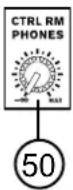
50. Control Room / Phones Control
This control is used to adjust the audio level of the Control Room and Phones feeds, for use in the monitoring and tracking of audio. The signal is then sent to the Control Room outputs on the rear of the mixer, as well as the Phones jack on the face of the mixer.
Typically, the signal sent to the Control Room and Phones mixing buses will be the Main L and R signal, however if any AFL (After-fader listen) buttons are pushed, they will take precedent over the Main L and R signal. If, however, a PFL (Pre-fader listen) is pushed, that will be the signal heard instead of either the AFL or Main L and R signals (as shown in the table below).
| Priority Signal | |
| High From PFL | |
| Medium From AFL | |
| Low Main L/R |
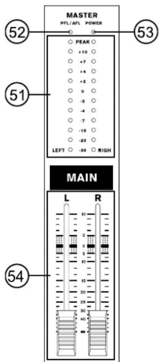
51. Level Meter
These 12 segment level meters give an accurate indication the level of the Main left and right audio signals. The 0 dB indicator illuminates is approximately equal to an output level of +4 dBu (balanced), and the PEAK indicator illuminates about 1.5 dB before the signal is dynamically clipped. To make the maximum use of audio, set the various level controls so that it sits steadily around 0 dB to make full use of audio, while still maintaining fantastic clarity.
If any PFL or AFL buttons are activated, the Main L/R Level Meter will display the properties of the Control Room / Phones signal instead.
52. PFL/AFL Indicator
The PFL/AFL indicator on the top of this meter is bi-colored, and illuminates green when a PFL switch is active and red for an AFL. Due to the fact that any PFL has priority over any AFL (see section 49), if both an AFL and PFL are activated, only the green PFL indicator will illuminated and processed by the CTRL RM/PHONES control area.
53. Power Indicator
The Power Indicator will light up when the power of the mixer is on; in case you weren't too sure.
54. Main L/R Faders
These fader are the final level control for the Main Left and Right audio feeds, sent to the Main Left and Right outputs on the rear of the device. When pushed all the way up, the Main L/R fader provides 10 dB of gain to the signal, and when set all the way down, the signal is effectively muted.
SPECIFICATIONS
| AM821X AM1221X AM1621X AM2421X | ||||
| Inputs | ||||
| Balanced Mic / Line channel 8 12 16 24 | ||||
| Stereo channel with mic preamp 2 2 2 2 | ||||
| Stereo Aux Returns 2 2 2 2 | ||||
| 2T Input Mini stereo and stereo RCA | ||||
| Outputs | ||||
| Main L/R Stereo 2 x 1/4" TS, Unbal. & 2 x XLR | ||||
| Main Mono 1 x 1/4" TS, Unbal. & 1 x XLR | ||||
| Aux sends 4, 4x 1/4" TS Unbal & 2x XLR | ||||
| Rec Out with Trim Control Mini stereo and stereo RCA | ||||
| CTRL RM L/R | 2 x 1/4" TS | 2 x 1/4" TS | 2 x 1/4" TS | 2 x 1/4" TS |
| Phones | 1 1 1 1 | |||
| Channel Strips | 10 14 18 26 | |||
| Aux Sends | 4 4 4 4 | |||
| Pan/Balance Control | Yes | Yes | Yes | Yes |
| Channel On/Mute | Yes | Yes | Yes | Yes |
| Channel Solo(PFL) with metering | Yes | Yes | Yes | Yes |
| LED indicators | Mute/Peak, Signal/PFL | |||
| Volume Controls | 60mm fader | 60mm fader | 60mm fader | 60mm fader |
| Master Section | ||||
| Aux Send Masters 4 4 4 4 | ||||
| Master Aux Send Solo(AFL) | 4 4 4 4 | |||
| Stereo Aux Returns | 2 2 2 2 | |||
| Effects Return to Monitor | 3 3 3 3 | |||
| Faders (60 mm) | Efx Rtn, Aux 1, Aux 2, Mono, Main L/R | |||
| Metering | ||||
| Number of Channels | 2 2 2 2 | |||
| Segments | 12 12 12 12 | |||
| Phantom Power Supply | +48V DC | +48V DC | +48V DC | +48V DC |
| Switches | Master | Master | Master | Master |
| Effect Processor(32-bit DSP) | 16 effects with one main parameter control, tap delay control,foot switch jacks (effect on/off, tap) | |||
| Frequency Response (Mic input to any output) | ||||
| 20Hz ~ 60KHz | +0/-1 dB | +0/-1 dB | +0/-1 dB | +0/-1 dB |
| 20Hz ~ 100KHz | +0/-3 dB | +0/-3 dB | +0/-3 dB | +0/-3 dB |
| Crosstalk (1KHz @ 0dBu, 20Hz to 20KHz bandwidth, channel in to main L/R outputs) | ||||
| Channel fader down, other channelsat unity | <-90 dB | <-90 dB | <-90 dB | <-90 dB |
| Noise (20Hz~20KHz; measured at main output, Channels 1-4 unit gain; EQ flat; all channels on main mix; channels 1/3 as far left as possible, channels 2/4 as far right as possible. Reference=+6dBu) | ||||
| Master @ unity, channel fader down | -86.5 dBu | -86.5 dBu | -86.5 dBu | -86.5 dBu |
| Master @ unity, channel fader @unity | -84 dBu | -84 dBu | -84 dBu | -84 dBu |
AM821X AM1221X AM1621X AM2421X
| S/N ratio, ref to +4" not 98145.451 >90 dB >90 dB >90 dB >90 dB | ||||
| Microphone Preamp E.I.N. (150 ohms terminated, max gain) | <-129.5 dBm <-129.5 dBm <-129.5 dBm <-129.5 dBm | |||
| THD (Any output, 1KHz @ +14dBu, 20Hz to 20KHz, channel inputs) | <0.005% <0.005% <0.005% <0.005% | |||
| CMRR (1 KHz @ -60dBu, Gain at maximum) | 80dB 80dB 80dB 80dB | |||
| Maximum Level | ||||
| Mic Preamp Input +10dBu +10dBu +10dBu +10dBu | ||||
| All Other Input +22dBu +22dBu +22dBu +22dBu | ||||
| Unbalanced Output +22dBu +22dBu +22dBu +22dBu | ||||
| Balanced Output +28dBu +28dBu +28dBu +28dBu | ||||
| Impedance | ||||
| Mic Preamp Input | 2 K ohms | 2 K ohms | 2 K ohms | 2 K ohms |
| All Other Input (except insert) | 10 K ohms | 10 K ohms | 10 K ohms | 10 K ohms |
| All other output | 100 ohms | 100 ohms | 100 ohms | 100 ohms |
| RCA 2T Output | 1.1 K ohms | 1.1 K ohms | 1.1 K ohms | 1.1 K ohms |
| Equalization | 3-band, +/-15dB | 3-band, +/-15dB | 3-band, +/-15dB | 3-band, +/-15dB |
| Low EQ | 80Hz 80Hz 80Hz 80Hz | |||
| Mid EQ (mono channel) | 100-8k Hz, sweepable | 100-8k Hz, sweepable | 100-8k Hz, sweepable | 100-8k Hz, sweepable |
| Mid EQ (stereo channel) | 800, 3k Hz | 800, 3k Hz | 800, 3k Hz | 800, 3k Hz |
| Hi EQ | 12 kHz | 12 kHz | 12 kHz | 12 kHz |
| Low cut filter (on mono channel) | 75 Hz (-18 dB/oct) | 75 Hz (-18 dB/oct) | 75 Hz (-18 dB/oct) | 75 Hz (-18 dB/oct) |
| Low pass filter on main mono output | 60-160 Hz variable (-12 dB/oct) | 60-160 Hz variable (-12 dB/oct) | 60-160 Hz variable (-12 dB/oct) | 60-160 Hz variable (-12 dB/oct) |
| Built-in Switching Power Supply | 100-240 VAC, 50/60 Hz | 100-240 VAC, 50/60 Hz | 100-240 VAC, 50/60 Hz | 100-240 VAC, 50/60 Hz |
| Net Weight | 7.2 kg (15.9 lbs) | 8.7 kg (19.2 lbs) | 10.5 kg (23.1 lbs) | 13.5 kg (29.7 lbs) |
| Dimensions (WxHxD) | 510x112x437.2 mm (20"x4.4"x17.2") | 642x112x437.2 mm (25.3"x4.4"x17.2") | 774x112x437.2 mm (30.5"x4.4"x17.2") | 1038x112x437.2 mm (40.9"x4.4"x17.2") |
SERVICE AND REPAIR
For replacement parts, service and repairs please contact the Phonic distributor in your country. Phonic does not release service manuals to consumers, and advice users to not attempt any self repairs, as doing so voids all warranties. You can locate a dealer near you at http://www.phonic.com/where/.
WARRANTY INFORMATION
Phonic stands behind every product we make with a no-hassles warranty. Warranty coverage may be extended, depending on your region. Phonic Corporation warrants this product for a minimum of one year from the original date of purchase against defects in material and workmanship under use as instructed by the user's manual. Phonic, at its option, shall repair or replace the defective unit covered by this warranty. Please retain the dated sales receipt as evidence of the date of purchase. You will need it for any warranty service. No returns or repairs will be accepted without a proper RMA number (return merchandise authorization). In order to keep this warranty in effect, the product must have been handled and used as prescribed in the instructions accompanying this warranty. Any tampering of the product or attempts of self repair voids all warranty. This warranty does not cover any damage due to accident, misuse, abuse, or negligence. This warranty is valid only if the product was purchased new from an authorized Phonic dealer/distributor. For complete warranty policy information, please visit http://www.phonic.com/warranty/.
CUSTOMER SERVICE AND TECHNICAL SUPPORT
We encourage you to visit our online help at http://www.phonic.com/support/. There you can find answers to frequently asked questions, tech tips, driver downloads, returns instruction and other helpful information. We make every effort to answer your questions within one business day.
support@phonic.com
http://www.phonic.com
PHONIC
Manual del Usuario
CONTENIDO
INTRODUCCIÓN 1
CARACTERISTÍCAS 1
CONTROLES Y AJUSTES
PANEL DE DORSO
ESPECIFICACIONES
| Program Parameter | Variable Range | ||
| 1 Hall | Reverb Time 0.3 - 10 sec | ||
| 2 Room | Reverb Time 0.3 - 3.2 sec | ||
| 3 Plate | Reverb Time 0.3 - 10 sec | ||
| 4 | Cathedral | Reverb Time 0.3 - 10 sec | |
| 5 Arena | Reverb Time 0.3 - 10 sec | ||
| 6 | Spring | Reverb Time 0.3 - 10 sec | |
| 7 | Opera | Reverb Time 0.3 - 10 sec | |
| 8 | Rev Vocal | Reverb Time 0.3 - 10 sec | |
| 9 | Slap Delay | Delay Time | 0 - 800 ms |
| 10 | Echo | Delay Time | 0 - 800 ms |
| 11 | Multi-Pong | Delay Time | 0 - 800 ms |
| 12 | Karaoke | Delay Time & Feedback | Delay Time: 160 - 260 ms; Feedback: 45-65 |
| 13 | Chorus + Rev | Depth | 0 - 100% |
| 14 | Flange + Rev | Modulation Frequency | 0.05 - 4.00 Hz |
| 15 | Phaser + Rev | Modulation Frequency | 0.05 - 4.00 Hz |
| 16 | Tap Delay | Feedback Gain | 0 - 99% |
APPLICATIONS APLICACIONES
PA OR LIVE EVENT SETUP
SETUP DE EVENTO PA O EN VIVO
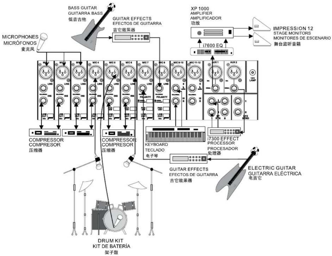
flowchart
graph TD
    A["MICROPHONES MICRÓFONOS 麦克风"] --> B["COMPRESSOR COMPRESOR 压缩器"]
    C["BASS GUITAR GUITARRA BASS 低音吉他"] --> D["GUITAR EFFECTS EFFECTOS DE GUITARRA 吉它效果器"]
    E["XP 1000 AMPLIFIER AMPLIFICADOR 功放"] --> F["IMPRESSION 12 STAGE MONITORS MONITORES DE ESCENARIO 舞台监听音箱"]
    G["IMPRESSOR COMPRESOR"] --> H["COMPRESSOR COMPRESOR 压缩器"]
    I["KEYBOARD TECLADO 电子琴"] --> J["GUITAR EFFECTS EFFECTOS DE GUITARRA 吉它效果器"]
    K["ELECTRIC GUITAR GUITARRA ELÉCTRICA 电吉它"] --> L["DRUM KIT KIT DE BATERÍA 架子鼓"]
    M["i7600 EQ"] --> N["i7300 EFFECT PROCESSOR PROCESADOR 处理器"]
CHURCH SETUP
SETUP DE IGLESIA
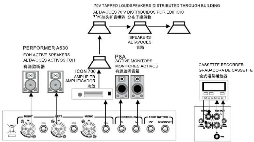
flowchart
graph TD
    A["70V TAPPED LOUDSPEAKERS DISTRIBUTED THROUGH BUILDING"] --> B["ALTAVOCES 70 V DISTRIBUIDOS POR EDIFICIO"]
    B --> C["70V 抽头扩音喇叭 分布于建筑物"]
    C --> D["SPEAKERS ALTAVOCES 音箱"]
    D --> E["P8A"]
    E --> F["ICON 700 AMPLIFIER AMPLIFICADOR 功放"]
    F --> G["有源监听器"]
    F --> H["MONO"]
    F --> I["RANK"]
    F --> J["LANK"]
    F --> K["FOOT SWITCH"]
    F --> L["TAP"]
    F --> M["EFX ON/OFF"]
    N["CASSETTE RECORDER GRABADORA DE CASSETTE 盒式磁带播放器"] --> O["TAP OUT"]
    O --> P["FOH ACTIVE SPEAKERS ALTAVOCES ACTIVOS FOH"]
    P --> Q["有源监听器"]
    P --> R["MONO"]
    P --> S["RANK"]
    P --> T["LANK"]
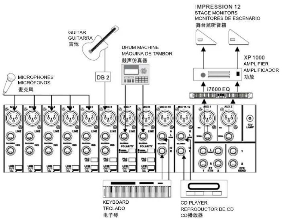
DIMENSIONS DIMENSIONES
- AM 821X AM 1221X AM 1621X AM 2421X
- USER'S MANUAL
- CONTENTS
- APPENDIX
- IMPORTANT SAFETY INSTRUCTIONS
- INTRODUCTION
- FEATURES
- BASIC SETUP
- GETTING STARTED
- CHANNEL SETUP
- MAKING CONNECTIONS CONNECTING PANEL
- XLR Jacks
- Line In Jacks
- Insert Jacks
- Stereo Channels
- Stereo Returns
- Auxiliary (AUX) 1 and 2 Outputs
- REAR PANEL
- Foot Switch Jacks
- Control Room / Phones
- Mono / Subwoofer Output
- Main Outputs
- 12V Lamp
- Power Connector
- MAIN MIXING PANEL
- Tape Inputs
- Record Outputs
- Headphones Output
- CONTROLS AND SETTINGS
- Power Switch
- CHANNEL CONTROLS
- Low Cut Filter (75 Hz)
- PAD Button (Stereo Channels Only)
- Gain Control
- High Frequency Control
- Middle Frequency Control
- Low Frequency Control
- AUX Controls
- EFX 1 and 2
- Pan/Balance Controls
- Mute Button
- Peak Indicator
- Sig Indicator
- PFL Button
- Channel Level Control
- DIGITAL EFFECT ENGINE
- Program Control
- Peak Indicator
- Parameter Control
- Tap Delay Button and Indicator
- To Aux 1 and 2 Controls
- Mute Button
- PFL Button
- DSP Effects Fader
- TAPE IN SECTION
- Level Control
- CTRL RM and MAIN Buttons
- To AUX 1 and 2 Controls
- MASTER CONTROL SECTION
- Stereo Return To AUX 1 and 2 Controls
- Stereo Return Level Controls
- Stereo Return PFL Buttons
- AUX 1 and 2 Master Controls
- Phantom Power Button and Indicator
- EFX Send 1 and 2 Master Controls
- Mono Channel Controls
- Control Room / Phones Control
- Level Meter
- PFL/AFL Indicator
- Power Indicator
- Main L/R Faders
- SERVICE AND REPAIR
- WARRANTY INFORMATION
- CUSTOMER SERVICE AND TECHNICAL SUPPORT
- Manual del Usuario
- CONTENIDO
- CONTROLES Y AJUSTES
- PANEL DE DORSO
- APPLICATIONS APLICACIONES
- DIMENSIONS DIMENSIONES
Brand : PHONIC
Model : AM 1621X
Category : Mixer