
PLE-30-080 - Electric controller Showtec - Free user manual and instructions
Find the device manual for free PLE-30-080 Showtec in PDF.


| Product Type | LED PAR Can |
| Model | PLE-30-080 |
| Brand | Showtec |
| Light Source | 30x 8W RGBW LEDs |
| Beam Angle | 25° (standard) |
| Power Consumption | 240W |
| Input Voltage | 100-240V AC, 50/60Hz |
| Dimensions (LxWxH) | 290 x 230 x 330 mm |
| Weight | 4.5 kg |
| DMX Channels | 4/8/12 selectable |
| Control Protocol | DMX512 |
| Operating Modes | DMX, Master/Slave, Auto, Sound Active |
| Strobe Rate | 0-20 Hz |
| Dimmer | 0-100% linear |
| Housing Material | Aluminum die-cast |
| Cooling | Fan cooled |
| IP Rating | IP20 (indoor use) |
| Safety Features | Overheat protection, safety cable attachment point |
| Maintenance | Clean lens with soft cloth; check ventilation grills regularly |
| Spare Parts | LED modules, power supply, control board, fans (contact dealer) |
Frequently Asked Questions - PLE-30-080 Showtec
User questions about PLE-30-080 Showtec
0 question about this device. Answer the ones you know or ask your own.
Ask a new question about this device
Download the instructions for your Electric controller in PDF format for free! Find your manual PLE-30-080 - Showtec and take your electronic device back in hand. On this page are published all the documents necessary for the use of your device. PLE-30-080 by Showtec.
USER MANUAL PLE-30-080 Showtec
Safety Instructions 2
Operating Determinations 4
Rigging 4
Return Procedure....5
Claims....5
Description of the device....6
Features 6
Frontside....6
Backside 7
Functional Description....8
Installation....9
Set Up and Operation....9
Forward Rotation / Up....9
Backwards Rotation / Down....9
Idle Position (0) 9
Emergency Stop....9
Pin Assignment for a 16-pin Harting socket....10
Maintenance....10
Troubleshooting ....11
Exploded View ....12
Parts 13
Connection Diagram....14
Declaration of Conformity 15
Product Specifications....16
Dimensions....17
Warning

For your own safety, please read this user manual carefully before your initial start-up!

Unpacking Instructions
Immediately upon receiving this product, carefully unpack the carton and check the contents to ensure that all parts are present, and have been received in good condition. Notify the dealer immediately and retain packing material for inspection if any parts appear damaged from shipping or the carton itself shows signs of mishandling. Save the carton and all packing materials. In the event that a fixture must be returned to the factory, it is important that the fixture be returned in the original factory box and packing.
Your shipment includes:
• Showtec Chainhoist Controller with fixed 1,5m powercable
- User manual


CAUTION! Indoor use only!

Safety Instructions
Every person involved with the installation, operation and maintenance of this device has to:
• be qualified and have full knowledge of national regulations regarding electrical installation
• follow the instructions of this manual
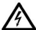
CAUTION! Be careful with your operations. With a dangerous voltage you can suffer a dangerous electric shock when touching the wires!

- This device contains no user-serviceable parts. Refer servicing to qualified technicians only.
- Before your initial start-up, please make sure that there is no damage caused by transportation. Should there be any, consult your dealer and do not use the device.
- To maintain perfect condition and to ensure a safe operation, it is absolutely necessary for the user to follow the safety instructions and warning notes written in this manual.
- Please consider that damages caused by manual modifications to the device are not subject to warranty and can lead to lethal injury.
• This device contains no user-serviceable parts. Refer servicing to qualified technicians only. - All selected electrical components meet the needs for industrial use and requirements stated in the EC machine directive, EN standards and IEC regulations.
- For indoor use only, controllers may only be used in areas, which are secured against environmental influences and with operating temperatures from -5 degree Celsius till +40 degree Celsius.
- Cabling should comply with the applicable standards.
- Decent plugs should be used.
- All external cabling should be tested on functionality and resistance in Ohms.
- Failures in cabling and plugs could cause malfunction of the hoist and controllers.
- We took every precaution to ensure the accuracy of this manual. However, no liability will be accepted for any errors written in this manual.
IMPORTANT:
The manufacturer will not accept liability for any resulting damages caused by the non-observance of this manual or any unauthorized modification to the device.
- Never let the power-cord come into contact with other cables! Handle the power-cord and all connections with the mains with particular caution!
- Never remove warning or informative labels from the unit.
- Never use anything to cover the ground contact.
- Never leave any cables lying around.
• Do not switch the device on and off in short intervals, as this would reduce the device's life.
- Do not shake the device. Avoid brute force when installing or operating the device.
- Avoid contact with water or other liquids.
- Only operate the fixture after having checked that the housing is firmly closed and all screws are tightly fastened.
• Only operate the device after having familiarized with its functions.
- Avoid flames and do not put close to flammable liquids or gases.
• Always allow free air space of at least 50 cm on the backside of the unit for ventilation.
• Always disconnect power from the mains, when device is not used or before cleaning! Only handle the power-cord by the plug. Never pull out the plug by tugging the power-cord.
• Make sure that the available voltage is not higher than stated on the rear panel.
- Make sure that the power-cord is never crimped or damaged. Check the device and the power-cord from time to time. If the powercord is damaged, return the device to an authorized dealer for repair.
- If device is dropped or struck, disconnect mains power supply immediately. Have a qualified engineer inspect for safety before operating.
- If the device has been exposed to drastic temperature fluctuation (e.g. after transportation), do not switch it on immediately. The arising condensation water might damage your device. Leave the device switched off until it has reached room temperature.
- If your Showtec device fails to work properly, discontinue use immediately. Pack the unit securely (preferably in the original packing material), and return it to your Showtec dealer for service.
- For qualified personnel use only. Make sure that the device is installed out of reach of unauthorized persons. Never leave the unit running unattended.
- The device must be installed by qualified personal according the national regulations. The manufacturer will not accept liability for damages caused by the misuse or incorrect installation of this device.
• The device must always be properly connected to the Protective Earth.
• Repairs, servicing and electric connection must be carried out by a qualified technician.
- WARRANTY: Till two year after date of purchase.

CAUTION!
Avoid danger and injury!
This chain host is only suitable for motors rated at a maximum of 1kW. Total load should not exceed 6,9kW.


CAUTION!
Do not use a Harting connector in combination with CEE sockets! Only use one type of connector/socket at a time!

Operating Determinations
- This device is not designed for permanent operation. Consistent operation breaks will ensure that the device will serve you for a long time without defects. Make sure to read the manual provided with the chainhoists connected for optimal use.
• The device is for indoor use -5^ ≥ t a = < 40^ .
• The relative humidity must not exceed 50 % at the maximum ambient temperature of 40^ C. - If this device is operated in any other way, than the one described in this manual, the product may suffer damages and the warranty becomes void.
- Any other operation may lead to lethal injuries.
You endanger your own safety and the safety of others!
Rigging
Please follow the European and national guidelines concerning rigging, trussing and all other safety issues.
Do not attempt the installation yourself!
Always let the installation be carried out by an authorized dealer!
Improper installation can cause serious damage to people and property!


Return Procedure

Returned merchandise must be sent prepaid and in the original packing, call tags will not be issued. Package must be clearly labeled with a Return Authorization Number (RMA number). Products returned without an RMA number will be refused. Highlite will not accept the returned goods or any responsibility. Call Highlite 0031-455667723 or mail aftersales@highlite.nl and request an RMA prior to shipping the fixture. Be prepared to provide the model number, serial number and a brief description of the cause for the return. Be sure to properly pack fixture, any shipping damage resulting from inadequate packaging is the customer's responsibility. Highlite reserves the right to use its own discretion to repair or replace product(s). As a suggestion, proper UPS packing or double-boxing is always a safe method to use.
Note: If you are given an RMA number, please include the following information on a piece of paper inside the box:
01) Your name.
02) Your address.
03) Your phone number.
04) A brief description of the symptoms.
Claims
The client has the obligation to check the delivered goods immediately upon delivery for any shortcomings and/or visible defects, or perform this check after our announcement that the goods are at their disposal. Damage incurred in shipping is the responsibility of the shipper; therefore the damage must be reported to the carrier upon receipt of merchandise.
It is the customer's responsibility to notify and submit claims with the shipper in the event that a fixture is damaged due to shipping. Transportation damage has to be reported to us within one day after receipt of the delivery.
Any return shipment has to be made post-paid at all times. Return shipments must be accompanied with a letter defining the reason for return shipment. Non-prepaid return shipments will be refused, unless otherwise agreed in writing.
Complaints against us must be made known in writing or by fax within 10 working days after receipt of the invoice. After this period complaints will not be handled anymore.
Complaints will only then be considered if the client has so far complied with all parts of the agreement, regardless of the agreement of which the obligation is resulting.
Description of the device
Features
The Showtec Showtec Chainhoist controller is a dedicated controller for all popular direct controlled chainhoists such as CM Lodestar.
- Each of the 8 hoists can be selected individually to go up or down or to be deselected as long as each individual motor output is rated for a maximum of 1kW and the total load of all motors summed should not exceed 6,9kW
• On the Backside: 4 x 4 pole CEE connectors and also 2x 16 pole multipin to connect a break/out box
• Power Supply: 400V \~ 3P + N + PE
• Max. voltage drop: -20% and +10%
• Power Connector: CEE 5 pole 32A
• Output Connector: CEE 4 pole 16A
• 2x 16 pole multi-connector (HARTING)
• Safety: Emergency button
- Compact strong metal housing
• Mains Circuit Breaker 4x 10A D
• Circuit breaker (for Run Switch +Stop button) 2A C
• Dimensions: 483 x 440 x 134 mm (LxWxH)
- Dimensions: 19" x 4U
- -5 degree Celsius till +40 degree Celsius
- Weight: 10,3 Kg
Frontside

Fig. 02
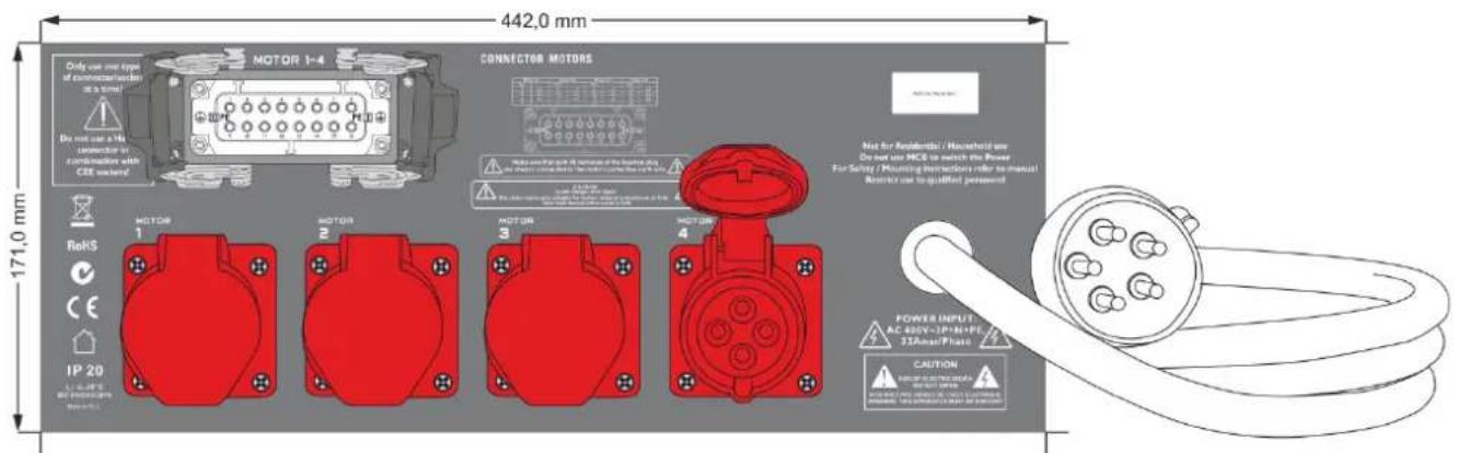
08) 16-pole multi-connector (Harting) for Motor 1-4
09) 16-pole multi-connector (Harting) for Motor 5-8
10) 4x CEE 4 pole 16A socket
11) CEE 5 pole 32A Powerconnector
Setup Possibilities PLE-30-080 (70281)
- 4x red CEE for Motor 1-4
- 1x Harting for Motor 1-4
- 1x Harting for Motor 5-8
- 2x Harting for Motor 1-4 + Motor 5-8

CAUTION!
Do not use a Harting connector in combination with CEE sockets! Only use one type of connector/socket at a time!

When the chainhoist controller is NOT used, disconnect the power cord.
Functional Description
01) Measure the main power supply and make sure the operating voltage is correct and all the phases are present and in correct order.
02) Check if the pre-selection switches for all hoists are in the "0" position.
03) Connect the chainhoists to the controller by either the using a HARTING 16p or the CEE connector.
04) Connect the controller to the powers supply by means of the 32A CEE plug.
05) Check that the emergency button is released.
06) Select a hoist and turn the switch in the up (1) or down (2) position. Turn the RUN switch to the right for 2 seconds to make sure the hoist has power. Also make sure that the running direction of the hoist matches the selected direction on your controller. The green LED lights up, when the black RUN switch is turned to the right. When the RUN switch is released, the green LED immediately dims and the switch will return to the OFF position.
07) If the direction of the hoist is not correct, change the phases.
08) If an individual hoist runs in the wrong direction, check the cabling and check the hoist.
09) Make sure that the load, that needs to be lifted, is in the correct position.
10) Clear the area from any obstacles that could jeopardize the operation.
11) No people are allowed under, on or in the vicinity of the load. Make sure all people have left the operating area, before you start to move any load.
12) Make sure you have an unobstructed view on the entire travel path of the load. Always keep an eye on the motors and workspace while operating the chainhoist controller.
13) Pre-select all hoists needed in the up or down direction.
14) Turn the black RUN switch to the right to activate all hoists and hold it until the load has reached the desired height. It may be necessary to level the rig at certain stages.
15) Never turn the RUN switch staccato (=often turning the Run switch within a few seconds). This can severely damage controller and hoist.
16) If the desired height is reached, release the RUN switch. When you release the Run switch, it will return to the OFF position.
17) Always disconnect power from the mains, when device is not used.
NEVER change the running direction of a hoist when the run switch is turned

All 3 red neon lamps L1,L2, L3 must be ON. Otherwise one of the phases is not present. Do NOT hoist.

Only use cable and connectors, which are in good condition.

Never connect more than one hoist per channel.

Make sure that the total current draw of the connected devices, does not exceed the maximum allowed input current.

This device is meant for professional use and should only be used in a professional environment.

Follow all warnings and guidelines in this manual Otherwise it could cause severe injuries or even death !!!.


CAUTION!
Do not use a Harting connector in combination with CEE sockets! Only use one type of connector/socket at a time!

Installation
Remove all packing materials from the Chainhoist controller. Check if all foam and plastic padding is removed. Connect all cables.
Do not supply power before the whole system is set up and connected properly.
Always disconnect from electric mains power supply before cleaning.
Damages caused by non-observance are not subject to warranty.
Installation should be done according national regulations.
The Chainhoist controller has to be mounted between a minimum height of 0.8m and a maximum height of 1.60m, due to the presence of an emergency stop button.
Set Up and Operation
Follow the directions below, as they pertain to your preferred operation mode.
Before plugging the unit in, always make sure that the power supply matches the product specification voltage.
This is a versatile 10A three-phase, 8-way motor commander with two HARTING sockets or 4 CEE sockets for output loading.
One 10 A residential circuit breaker and one 2 Amp MCB (main circuit breaker) are used for protection when a fault condition occurs or a voltage spike occurs.
The Forward, Backward Rotation and Idle modes are available by turning the switch on the front of the controller.
Forward Rotation / Up
When the chainhoist controller is powered on, select the desired motor and set the switch to the "UP" (1) position to access the Forward Rotation. Then turn the "RUN" switch to the right to start the forward/Up movement.
Backwards Rotation / Down
When the chainhoist controller is powered on, select the desired motor and set the switch to the "DOWN" (2) position to access the Backward Rotation. Then turn the "RUN" switch to the right to start the backward/Down movement.
Idle Position (0)
When the chainhoist controller is powered on, select the desired motor and set the switch to the "0" position to access to the Idle position. All eight outputs are isolated and no operation is possible.
Emergency Stop
In case of an emergency immediately press the RED emergency "STOP" button.
Pin Assignment for a 16-pin Harting socket
| Motor 1/5 | Motor 2/6 | Motor 3/7 | Motor 4/8 | ||||
| Pin | Pin | Pin | Pin | ||||
| 1 | L1 | 5 | L1 | 9 | L1 | 13 | L1 |
| 2 | L2 | 6 | L2 | 10 | L2 | 14 | L2 |
| 3 | L3 | 7 | L3 | 11 | L3 | 15 | L3 |
| 4 | - | 8 | - | 12 | - | 16 | - |


Make sure that both PE terminals of the inserted plug are always connected to the motor's protective earth wire.

Maintenance
The Showtec Chainhoist Controller requires almost no maintenance. However, you should keep the unit clean.
Disconnect the mains power supply and then wipe the cover with a damp cloth. Wipe the front panel clean with mild detergent and a soft cloth. Do not use alcohol or solvents. The front panel will require weekly cleaning, as smoke-fluid tends to build up residues. Do not immerse in liquid.
Keep connections clean. Disconnect electric power, and then wipe the connections with a damp cloth. Make sure connections are thoroughly dry before linking equipment or supplying electric power.
The operator has to make sure that safety-relating and machine-technical installations are to be inspected by an expert after every year in the course of an acceptance test.
The operator has to make sure that safety-relating and machine-technical installations are to be inspected by a skilled person once a year.
The following points have to be considered during the inspection:
01) All screws used for installing the device or parts of the device have to be tightly connected and must not be corroded.
02) There may not be any deformations on housings, fixations and installation spots.
03) Mechanically moving parts like axles, eyes and others may not show any traces of wearing.
04) The electric power supply cables must not show any damages or material fatigue.
Troubleshooting
This troubleshooting guide is meant to help solve simple problems.
If a problem occurs, carry out the steps below in sequence until a solution is found. Once the unit operates properly, do not carry out following steps.
| Hoist(s) do not respond to the green RUN signal | Solution |
| Please check the cabling and the connections | Connect everything properly |
| The corresponding switch is set in the “0” position | Set the switch in the Up/Down position |
| The main circuit breaker is OFF | Set the main circuit breaker to ON |
| The red Emergency button is pressed | Turn the emergency button clockwise to release. |
| Controller does not respond | Solution |
| Please check the powercable and the connections to the chainhoists. | Connect everything properly. |
| All 3 red neon lamps (L1, L2, L3) must be ON, Otherwise one of the phases is not present.DO NOT HOIST !! | Please check all 3 phases |
| The main circuit breaker is switched OFF | Set the main circuit breaker to ON |
| Control circuit breaker is switched OFF | Set the switch to ON |
| The red Emergency button is pressed | Control the area underneath the chainhoist for any emergency situation, if this is ok turn the emergency button clockwise to release |
| The surrounding temperature is too high/too low | Place the chainhoist controller in a cooler/warmer place |
If the problem is not solved, immediately return your device unit to an authorised dealer.
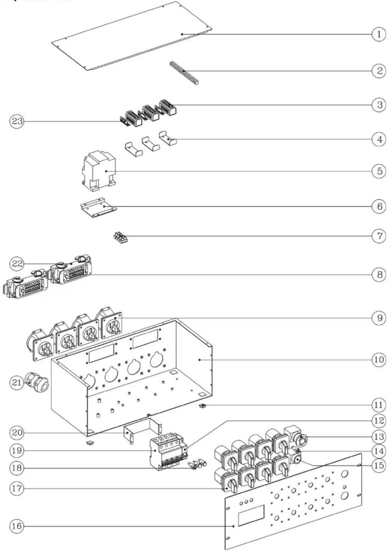
Exploded View
Parts
| 1 | Top cover |
| 2 | Brass bar for E-line |
| 3 | Terminal block |
| 4 | Aluminum bracket for holding terminal |
| 5 | AC relay |
| 6 | Aluminum fix stand for remaining Relay |
| 7 | 12-way connecting terminal block |
| 8 | ILME socket, female |
| 9 | Power outlet, CEE socket, 4-pin female |
| 10 | Chassis/Base case |
| 11 | Rubber case feet |
| 12 | MCB, 2-pole |
| 13 | Push knob for emergency stop(red) |
| 14 | Indicator(green) |
| 15 | Turn switch for emergency start(black) |
| 16 | Front panel |
| 17 | Universal Changeover Switch |
| 18 | Indicator(red) |
| 19 | MCB, 4-pole |
| 20 | Aluminum frame for fixing MCB |
| 21 | Cable nut |
| 22 | ILME chassis |
| 23 | Brass bar of terminal block |

natural_image
Line drawing of a rectangular electronic device with multiple switches and ports (no text or symbols)Connection Diagram
Appendix ii:Interior Connection Diagram

Declaration of Conformity

DECLARATION OF CONFORMITY
Product Details
| Product Name |
| PLE-30-080 |
| Ordercode |
| 70283 |
| Trade Name |
| Showtec |
Applicable Standards Details
Low Voltage Directive : 2006/95/EC
EN 61439-2: 2012
EN 60204-32: 2008 Clause 7.3.1
ISO 12100: 2011
Supplementary Information
The conformity to above standards is verified by TUV Rheinland EPS.
Declaration
I hereby declare under our sole responsibility that the product forementioned, to which this declaration relates, complies with the above mentioned Standards and Directives.
Highlite International BV. Vestastraat 2, 6468 EX Kerkrade, The Netherlands
Name
Issued Date
H. De la Haye / Director
May 27, 2015

Signature of representative
Product Specifications
| Model: | Chainhoist controller |
| Power Supply: | 400V ~ 3P + N +PE |
| Max. voltage drop: | -20% and +10% |
| Max. Load per motor switch | 1 kW (1,5A 400V) |
| Max. load total, all outputs summed | 6,9 kW (10A 400V) |
| Rated Voltage of the assembly (Un) | 400V |
| Rated Insulation voltage (Ui) | 500V |
| Rated Impulse voltage (Uimp) | 6kV |
| Rated Current of the assembly (InA) | 10A |
| Rated peak withstand current (Ipk) | 120A |
| Rated conditional short circuit current of an assembly (Icc) | 6kA |
| Rated Diversity Factor (RDF) | 1 |
| Rated Frequency (fn) | 50/60Hz |
| Pollution Degree | 3 |
| Complies to standard | IEC-61439-2 : 2011 |
| Dimensions: | 483 x 440 x 134 mm (LxWxH) |
| Dimensions: 19" x 4 | |
| Weight: | 10,3 Kg |
| Operation | |
| Power Connector: | CEE 5 pole 32A |
| Output Connector: | 4x CEE 4 pole 16A |
| 2x 16 pole multi-connector (HARTING) | |
| Safety: | Emergency button |
| Housing | Compact strong metal housing |
| Mains Circuit Breaker | 4x 10A D |
| Circuit breaker (for Run switch + Stop button) | 2A C |
| Max. ambient temperature to: | 40°C |
Design and product specifications are subject to change without prior notice.
CE
Website: www.Showtec.info
Email: service@highlite.nl
Dimensions


natural_image
Technical line drawing of a rectangular frame with three vertical supports and a horizontal dimension label (278) at the top, no readable text or symbols present.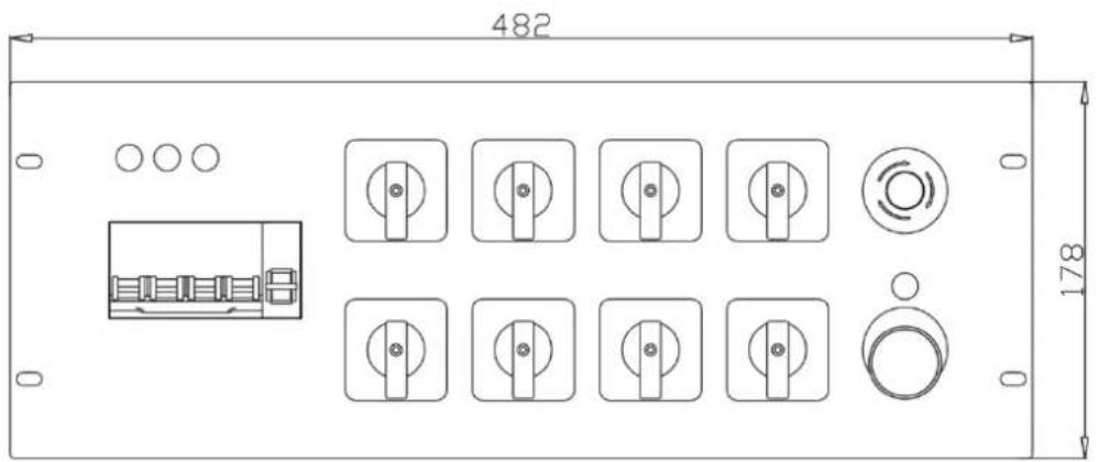

- Description of the device....6
- Functional Description....8
- Installation....9
- Set Up and Operation....9
- Maintenance....10
- Troubleshooting ....11
- Declaration of Conformity 15
- Product Specifications....16
- Dimensions....17
- Warning
- Unpacking Instructions
- Your shipment includes:
- Safety Instructions
- IMPORTANT:
- CAUTION!
- Operating Determinations
- Rigging
- Return Procedure
- Note: If you are given an RMA number, please include the following information on a piece of paper inside the box:
- Claims
- Description of the device
- Features
- Setup Possibilities PLE-30-080 (70281)
- Functional Description
- Installation
- Set Up and Operation
- Forward Rotation / Up
- Backwards Rotation / Down
- Idle Position (0)
- Emergency Stop
- Pin Assignment for a 16-pin Harting socket
- Maintenance
- Troubleshooting
- Connection Diagram
- Declaration of Conformity
- Applicable Standards Details
- Supplementary Information
- Declaration
- Dimensions
Brand : Showtec
Model : PLE-30-080
Category : Electric controller