1000A - Multimeter Owon - Free user manual and instructions
Find the device manual for free 1000A Owon in PDF.


| Product Type | Digital Clamp Multimeter with Oscilloscope |
| Brand | Owon |
| Model | 1000A |
| Measurement Category | CAT III 1000V, CAT IV 600V |
| Dimensions | 248mm (L) x 94.5mm (W) x 37.8mm (D) |
| Weight | Approx. 0.35 kg |
| Power Supply | Single section 18650 3.7V lithium battery |
| Battery Life | Approx. 18.5 hours (peak discharge) |
| Charging Time | Approx. 8 hours via USB-C |
| Display | 2.8 inch LCD |
| DC Voltage Range | 20.000mV to 1000.0V |
| AC Voltage Range | 200.00mV to 1000.0V (True RMS) |
| DC Current Range | 20.00A to 1000A |
| AC Current Range | 20.00A to 1000A (True RMS) |
| Resistance Range | 200.00Ω to 100.00MΩ |
| Capacitance Range | 2.000nF to 20.00mF |
| Frequency Range | 200.00Hz to 20.000MHz |
| Continuity Test | Yes, buzzer below 50Ω |
| Diode Test | Yes, up to 3.0000V |
| NCV (Non-Contact Voltage) | Yes, 4-level detection |
| Oscilloscope Bandwidth | 1 MHz (voltage), 1 kHz (current) |
| Oscilloscope Sample Rate | 5.0 MSa/s (real-time) |
| Bluetooth Connectivity | Yes, for app remote control and data logging |
| Auto Power Off | Yes, default 10 minutes (can be disabled) |
| Accessories Included | 1 set of probes, 1 quick guide, 1 USB-C cable |
Frequently Asked Questions - 1000A Owon
User questions about 1000A Owon
0 question about this device. Answer the ones you know or ask your own.
Ask a new question about this device
Download the instructions for your Multimeter in PDF format for free! Find your manual 1000A - Owon and take your electronic device back in hand. On this page are published all the documents necessary for the use of your device. 1000A by Owon.
USER MANUAL 1000A Owon
For product support, visit:www.owon.com.hk/download
※: The illustrations, interface, icons and characters in the user manual may be slightly different from the actual product. Please refer to the actual product.
Oct. 2024 edition V1.0.1
Copyright © LILLIPUT Company. All rights reserved.
The LILLIPUT's products are under the protection of the patent rights, including ones which have already obtained the patent rights and those which are applying for. The information in this manual will replace all materials published.
The information in this manual was correct at the time of printing. However, LILLIPUT will continue to improve products and reserves the rights to change specification at any time without notice.
owon ^® is the registered trademark of the LILLIPUT Company.
Fujian LILLIPUT Optoelectronics Technology Co., Ltd.
No. 19, Heming Road
Lantian Industrial Zone, Zhangzhou 363005 P.R. China
Tel: +86-596-2130430 Fax: +86-596-2109272
Web: www.owon.com E-mail: info@owon.com.cn
General Warranty
We warrant that the product will be free from defects in materials and workmanship for a period of 1 years from the date of purchase of the product by the original purchaser from our company. This warranty only applies to the original purchaser and is not transferable to a third party.
If the product proves defective during the warranty period, we will either repair the defective product without charge for parts and labour, or will provide a replacement in exchange for the defective product. Parts, modules, and replacement products used by our company for warranty work may be new or reconditioned like new. All replaced parts, modules and products become the property of our company.
In order to obtain service under this warranty, the customer must notify our company of the defect before the expiration of the warranty period. Customer shall be responsible for packaging and shipping the defective product to the designated service centre, a copy of the customers proof of purchase is also required.
This warranty shall not apply to any defect, failure or damage caused by improper use or improper or inadequate maintenance and care.
We shall not be obligated to furnish service under this warranty a) to repair damage resulting from attempts by personnel other than our company representatives to install, repair or service the product; b) to repair damage resulting from improper use or connection to incompatible equipment; c) to repair any damage or malfunction caused by the use of not our supplies; or d) to service a product that has been modified or integrated with other products when the effect of such modification or integration increases the time or difficulty of servicing the product.
Please contact the nearest Sales and Service Offices for services.
Excepting the after-sales services provided in this summary or the applicable warranty statements, we will not offer any guarantee for maintenance declared or hinted, including but not limited to the implied guarantee for marketability and special-purpose acceptability. We should not take any responsibilities for any indirect, special, or consequent damages.
Table of Contents
1. Safety Information 1
General Safety Requirements....1
Measurement Category .... 3
Safety Terms and Symbols 4
2. Quick Start ....5
General Inspection....5
Install the Battery 5
Power on/off....6
Selecting the Range....6
3. Instrument Panel ....7
Front Panel and Keys....7
4. How to Use the Multimeter 9
About This Chapter....9
Instrument Interface....9
Input terminals....11
Making Measurements....11
Measuring DC or AC Current....11
Measuring AC or DC Voltage....13
Measuring Resistance 15
Measuring Continuity....16
Measuring Diodes....17
Measuring Capacitance 18
Measuring Frequency 19
Measuring NCV....20
Multimeter Features....21
Setting Scale 21
Setting Range 21
Making Max/Min Measurements....22
Making Relative Measurements....22
Value Hole Mode....23
5. How to Use the Oscilloscope 25
Introduction to the User Interface of the Oscilloscope 25
Measuring System 26
Automatic Measurement....26
System Settings....27
How to use Bluetooth 28
6. Technical Specifications ....30
Multimeter Specification....30
Oscilloscope Specification 32
7. Appendix 34
Appendix A: List of Accessories 34
Appendix B: Maintenance and Cleaning 34
General maintenance 34
Charging and Replacement of Battery 35
Replacement of Lithium Battery 35
1. Safety Information
(Be sure to read the safety information before using this product.)
General Safety Requirements
Before any operations, please read the following safety precautions to avoid any possible bodily injury and prevent this product or any other products connected from damage. In order to avoid any contingent danger, this product is only used within the range specified.
■ Limit operation to the specified measurement category, voltage, or amperage ratings.
■ Do not use the digital clamp meter if it is damaged. Before you use the digital clamp meter, inspect the case. Look for cracks or missing plastic. Pay particular attention to the insulation surrounding the connectors.
■ Do not use the test leads provided for other products. Use only the certified test leads specified for this product.
■ Inspect the test leads for damaged insulation or exposed metal.
■ Before use, verify the digital clamp meter's operation by measuring a known voltage.
■ Only the qualified technicians can implement the maintenance.
■ Always use the specified battery type. The power for the digital clamp meter is supplied with a battery. Observe the correct polarity markings before you insert the batteries to ensure proper insertion of the batteries in the digital clamp meter.
■ Check all Terminal Ratings. To avoid fire or shock hazard, check all ratings and markers of this product. Refer to the user's manual for more information about ratings before connecting to the digital clamp meter.
■ Do not operate the digital clamp meter with the cover or portions of the cover removed or loosened.
■ Do not operate if in any doubt. If you suspect damage occurs to the digital clamp meter, have it inspected by qualified service personnel before further operations.
■ Do not operate this product in wet or damp conditions.
■ Do not operate in an explosive atmosphere.
- Keep product surfaces clean and dry.
■ Do not apply more than the rated voltage (as marked on the digital clamp meter) between terminals, or between terminal and earth ground.
■ When measuring current, turn off the circuit power before connecting the digital clamp meter in the circuit. Remember to place the digital clamp meter in series with the circuit.
■ When servicing the digital clamp meter, use only the specified replacement parts.
■ Use caution when working above 60 V DC, 30 V AC RMS, or 42.4 V peak. Such voltages pose a shock hazard.
■ When using the test leads, keep your fingers behind the finger guards on the test leads.
■ Remove the test leads from the digital clamp meter before you open the battery cover.
■ To avoid false readings, which may lead to possible electric shock or personal injury, replace the battery as soon as the low battery indicator appears and flashes.
■ Disconnect circuit power and discharge all high-voltage capacitors before testing resistance, continuity, diodes, or capacitance.
■ Use the proper terminals, function, and range for your measurements.
When the range of the value to be measured is unknown, set the rotary switch position as the highest range, or choose the auto ranging mode. To avoid damages to the digital clamp meter, do not exceed the maximum limits of the input values shown in the technical specification tables.
■ Connect the common test lead before you connect the live test lead. When you disconnect the leads, disconnect the live test lead first.
■ Before changing functions, disconnect the test leads from the circuit under test.
Measurement Category
The digital clamp meter has a safety rating of 1000 V, CAT III and 600V, CAT IV.
Measurement category definition
Measurement CAT I applies to measurements performed on circuits not directly connected to the AC mains. Examples are measurements on circuits not derived from the AC mains and specially protected (internal) mains-derived circuits.
Measurement CAT II applies to protect against transients from energy-consuming equipment supplied from the fixed installation, such as TVs, PCs, portable tools, and other household circuits.
Measurement CAT III applies to protect against transients in equipment in fixed equipment installations, such as distribution panels, feeders and short branch circuits, and lighting systems in large buildings.
Measurement CAT IV applies to measurements performed at the source of the low-voltage installation. Examples are electricity meters and measurements on primary over current protection devices and ripple control units.
Safety Terms and Symbols
Safety Terms
Terms in this Manual. The following terms may appear in this manual:

Warning: Warning indicates the conditions or practices that could result in personal injury or death.

Caution: Caution indicates the conditions or practices that could result in damage to this product or other property.
Terms on the Product. The following terms may appear on this product:
Danger: It indicates an injury or hazard may immediately happen.
Warning: It indicates an injury or hazard may be accessible potentially.
Caution: It indicates a potential damage to the instrument or other property might occur.
Safety Symbols
Symbols on the Product. The following symbol may appear on the product:
 | Direct current (DC) |  | Fuse |
 | Alternating current (AC) |  | Caution, risk of danger (refer to I manual for specific Warning or Caution information) |
 | Both direct and alternating current | CAT I | Category I overvoltage protection |
 | Ground terminal | CAT II | Category II overvoltage protection |
 | Conforms to European Union directives | CAT III | Category III overvoltage protection |
 | Equipment protected throughout by double insulatic or reinforced insulation | CAT IV | Category IV overvoltage protection |
2. Quick Start
General Inspection
After you get a newdigital clamp meter, make a check on the instrument according to the following steps:
1. Check whether there is any damage caused by transportation.
If it is found that the packaging carton or the foamed plastic protection cushion has suffered serious damage, do not throw it away first till the complete device and its accessories succeed in the electrical and mechanical property tests.
2. Check the Accessories
The supplied accessories have been already described in the Appendix A: Enclosure of this Manual. You can check whether there is any loss of accessories with reference to this description. If it is found that there is any accessory lost or damaged, please get in touch with our distributor responsible for this service or our local offices.
3. Check the Complete Instrument
If it is found that there is damage to the appearance of the instrument, or the instrument can not work normally, or fails in the performance test, please get in touch with our distributor responsible for this business or our local offices. If there is damage to the instrument caused by the transportation, please keep the package. With the transportation department or our distributor responsible for this business informed about it, a repairing or replacement of the instrument will be arranged by us.
Install the Battery
The digital clamp meter is powered by a 3.7V (18650) battery.

Warning: To avoid false readings, which could lead to possible ele shock or personal injury, replace the battery as soon as low battery indicator appears.
Before replacing the battery, turn off the meter, disconnect leads and any connectors from any circuit under test, rem test leads from the input terminals. Use only the specified
battery type.
Use the following procedure to install the battery:
(1) Power off, remove test leads and any connectors from the input terminals.
(2) Loosen the screws with a suitable Phillips screwdriver and remove the battery cover.
(3) Observe the battery polarity indicated inside the battery compartment, Insert the battery.
(4) Place the battery cover back in its original position and tighten the screws.

Caution: To avoid instruments being damage from battery leakage, remove the batteries and store them separately if the digital clamp meter is not going to be used for a long period.
Power on/off
It can be turned on in the following ways:
- Press the button at the bottom left of the host;
It can be turned off in the following ways:
- Manual shutdown,tap and hold button;
● Automatic shutdown, emit a short beep one minute before shutdown, emit a long beep during shutdown;
- Low power automatic shutdown.
Selecting the Range
- Auto ranging is set as default when the meter is powered on, Auto is displayed.
- Under automatic range, press ▲ or ▼ to enter the manual range mode.
- Under manual range, each additional press of ▲ sets the next higher range; each additional press of ▼ sets the next lower range.
- Under manual range, press A to enter the auto range mode.
Note: Manual range is not available when measuring capacitance, only in multimeter measurement mode.
3.Instrument Panel
Front Panel and Keys
The front panel and keys of the digital clamp meter are shown in Figure 3-1:
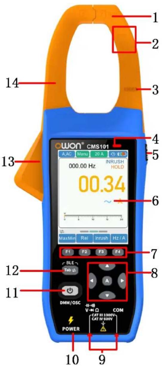
Figure 3- 1: Front panel
Description:
| Num | Illustration in multimeter mode | Illustration in oscilloscope mode |
| 1 | NCV measurement. | |
| 2 | Safety level. | |
| 3 | Maximum current allowed to be measured. | |
| 4 | Operation indicator light. | |
| 5 | Reading hold button. | Run/Stop button. |
| 6 | Display area. | |
| 7 | The F1 - F4 keys are multi-function keys. In each menu mode, the corresponding key to select the corresponding menu item. | |
| 8 | Function of direction keys: used for changing rangeFunction of key:Restore auto gear. | Function of direction keys: used for the voltage or current scales.Function of direction keys used for zooming waveforms and the time base changing.Function of key: Perform automatic setup. |
| 9 | Measurement input port: the input of the measurement signal. | |
| 10 | Charging port. | |
| 11 | Switch key for working state of oscilloscope and multimeter. Press power button briefly to turn on the device. After powering on, pre briefly to switch to the oscilloscope or multimeter mode. Press an to turn off the device. | |
| 12 | Tab function switch button. | |
| 13 | Clamp head trigger: Press the trigger to open the clamp heads; the trigger, and the clamp heads will automatically close. | |
| 14 | Clamp head: The current measurement sensor converts alternating direct current into voltage. | |
4.How to Use the Multimeter
About This Chapter
This chapter introduces the multimeter function and provides some basic examples of basic operations and how to use the menu.
Instrument Interface
The digital clamp meter uses four 2 safety banana plug input ends:COM and

Multimeter interface:
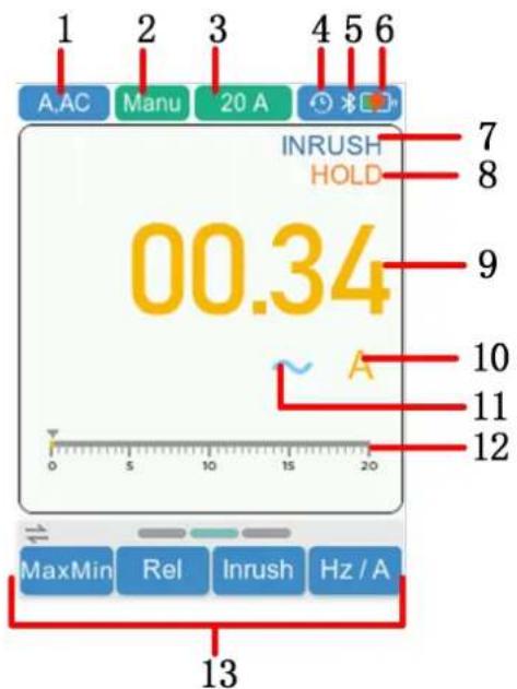
Figure 4-1: Multimeter interface
Description:
1. Measurement type indication:
| Measurement type | Description |
| A,DC | DC current measurement |
| A,AC | AC current measurement |
| V,DC、mV,DC | DC voltage measurement |
| V,AC、mV,AC | AC voltage measurement |
| Res | Resistance measurement |
| Cont | On/Off measurement |
| Diode | Diode measurement |
| Cap | Capacitance measurement |
| Freq | Frequency measurement |
| NCV | Non-contact AC voltage sensing |
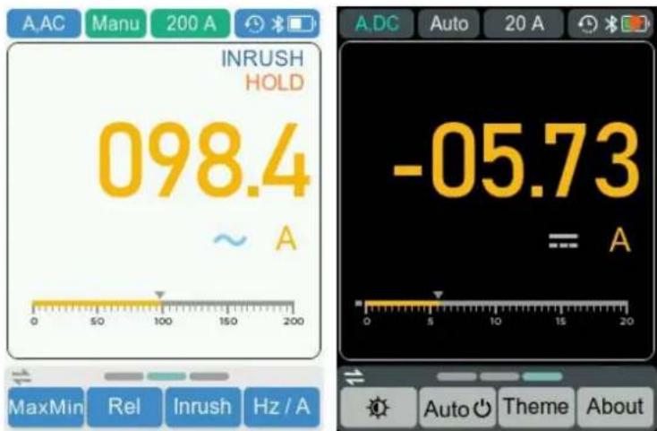
- Range indication: Manu means manual range; Auto means automatic range.
- Current measurement range.
- Automatic shutdown sign: Display the flag when enabled. Closing will hide the identity.
- Bluetooth sign: Display the flag when enabled. Closing will hide the identity.
- Battery power and external power supply indication.
- Inrush mode (Only in ACA mode).
- Reading hold mode.
- Current measurement menu.
- Current measurement unit
- DC/AC/On-Off/Diode/Capacitance mode.
- Range simulation strip.
- Operation menu.
Measurement units
| Sign | Description | |
| M | Mega | 1E+06 (1000000) |
| k | kilo | 1E+03 (1000) |
| m | milli | 1E-03 (0.001) |
| μ | micro | 1E-06 (0.000001) |
| n | nano | 1E-09 (0.000000001) |
| Sign | Description | Measurement type |
| V | Voltage | Voltage |
| A | Ampere | Current |
| Ohm | Resistance | |
| Hz | Hertz | Frequency |
| % | Percent | Duty cycle |
| F | Farad | Capacitance |
Input terminals
The terminal connections for the different measurement functions of the digital clamp meter are described in the table below.

Warning: Before starting any measurement, observe the rotary swit position of the digital clamp meter, and then connect the leads to the correct terminals.

Caution: To avoid damaging the digital clamp meter, do not exceed rated input limit.
| Measurement function | Input terminals | Overload protection |
 | 1000 VAC/1000 VDC | |
 | COM | 250 VAC/300 VDC |
 |
Making Measurements
Measuring DC or AC Current

Warning: Do not attempt to measure current if the open-circuit vol between the live and ground exceeds 250V, as this may damage the digital clamp meter and pose a risk of electr shock or personal injury.

Caution: - - To avoid damaging the digital clamp meter or the measured dev check the digital clamp meter before measuring current. Ensure
correct input terminals, function settings, and range are used for measurement.
- The current measurement function must be operated between 0°C and 40°C. Avoid suddenly releasing the trigger; the Hall effect is sensitive not only to magnetic fields but also to heat and mechanical stress. Impact can temporarily alter readings.
- For accurate measurement, ensure the conductor is positioned at center of the clamp heads. Positioning outside the center can introduce an additional error of ± 1.0% of the reading.
- Press to switch DC Current measurement mode, A, will be
displayed in the upper left corner.Then press to switch into AC Current measurement mode, AC will be displayed in the upper left corner.
- Hold the trigger to open the clamp heads. Place the conductor to be measured in the clamp and then slowly release the trigger until the clamp heads are fully closed. Ensure the conductor is centered in the clamp as shown in the diagram. If not centered, additional errors may occur. The clamp meter can measure only one current conductor at a time; measuring two or more conductors simultaneously will result in incorrect readings.
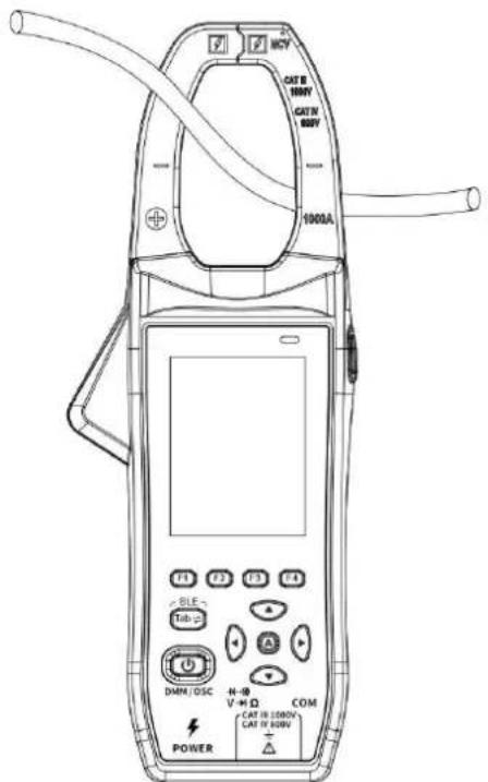
-
Read the display. Press or to enable and cycle through the manual ranges. If "OL" is displayed, it indicates the input exceeds.
-
In AC current mode, press the key to switch to the second page of the menu, then press the key to enable the surge current measurement mode. At this point, start the electrical device to measure its inrush current. Press the key again to exit this mode.
- In AC current mode, press the key to switch to the second page of the menu. Press the key again to enable the AC current frequency measurement mode. You can then directly read the frequency of the AC current from the display. Press the key once more to exit this mode.
Note:
- After testing DC current, especially with large currents, the open-circuit baseline might be high. Perform an AC current test to eliminate residual magnetic signals from the clamp heads.
- If there is residual magnetism, press the key to select "Zero." This will temporarily subtract the current residual magnetism from the readings. Note that the residual magnetism value will return after restarting the instrument.
Measuring AC or DC Voltage

Warning: Do not measure any voltage of over 1000 Vdc or 1000 rms to avoid instrument damage or electric shock. Do not apply more than 1000 Vdc or 1000 Vac rms between the common terminal and the earth ground to avoid instru damage or electric shock.
This digital clamp meter displays DC voltage values as well as their polarity. Negative DC voltages will display a negative sign on the left of the screen.
- Press to switch DC voltage measurement mode, *, wDCbe
displayed in the upper left corner (* denotes mV or V). Then press to switch into AC Voltage measurement mode AC*, will be displayed in the upper left corner (* denotes mV or V). And then press to switch into mV, V measurement function, press ▲ or ▼ to up and down
measurement scales.
-
Connect the black test lead to the terminal and the red test lead to the terminal.
-
Probe the test points and read the display, this is shown in the figure below. Press or to enable and cycle through the manual ranges.
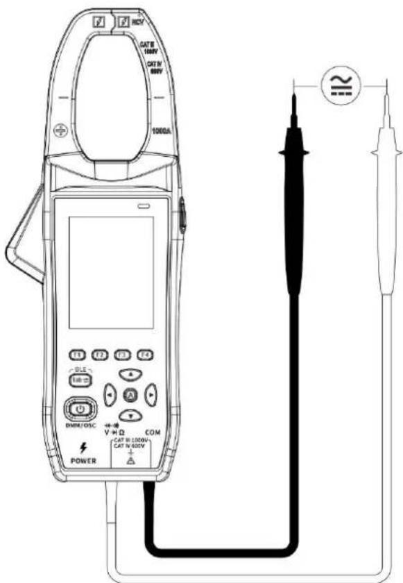
- In AC voltage mode, press the key to switch to the second page of
the menu. Press the key again to enable the AC voltage frequency measurement mode. You can then directly read the frequency of the AC voltage from the display. Press the key once more to exit this mode.
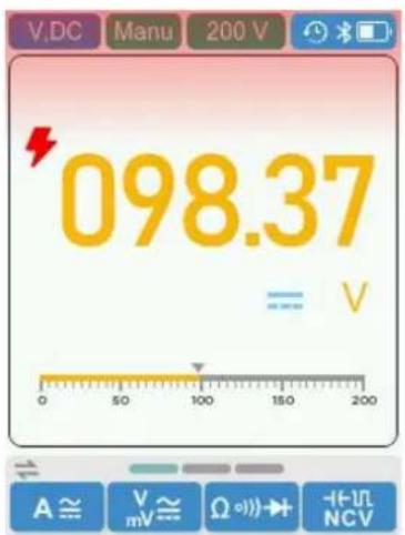
Note: When the measured voltage exceeds 42V DC, the instrument's LCD will display a high voltage warning symbol “” and the screen will show a red alert as shown in the image.
Measuring Resistance

Caution: To avoid possible damage to your digital clamp meter or equipment under test, disconnect the circuit power and discharge all high-voltage capacitors before measuring resistance.
- Press to enter resistance testing mode, Res will be displayed in the upper left corner.
- Connect the black test lead to the terminal and the red test lead to the terminal.
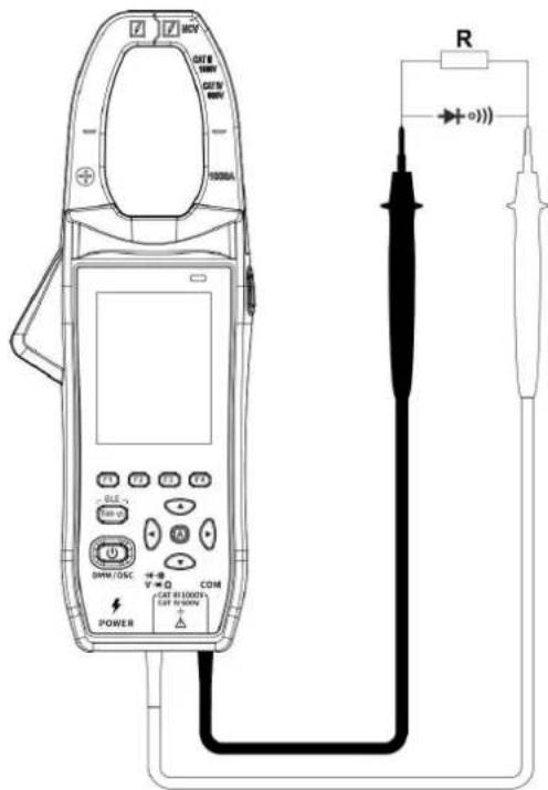
- Probe the test points to measure the resistance in the circuit, as shown in the image.
Measuring Continuity

Caution: To avoid possible damage to your digital clamp meter or equipment under test, disconnect the circuit power and discharge all high-voltage capacitors before testing for continuity.
- Press to enter continuity testing mode, Cont will be displayed in the upper left corner.
- Connect the black test lead to the terminal and the red test lead to the terminal.
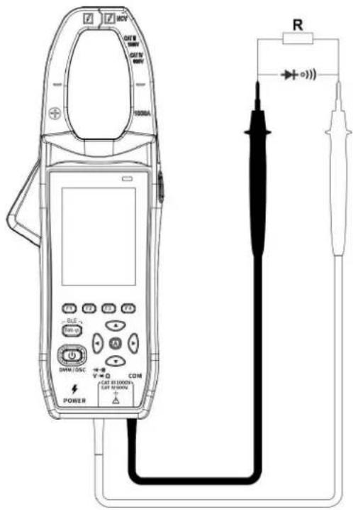
- Probe the test points to measure the resistance in the circuit, as shown in the image. If the reading is below 250 the digital clamp meter will beep continuously.
Measuring Diodes

Caution: To avoid possible damage to your digital clamp meter or equipment under test, disconnect the circuit power and discharge all high-voltage capacitors before testing diodes
- Press to enter diode testing mode, Diode will be displayed in the upper left corner.
- Connect the black test lead to the terminal and the red test lead to the 16-17 terminal.
- Connect the red test lead to the positive terminal of the diode and the black test lead to the negative terminal, as shown in the image.
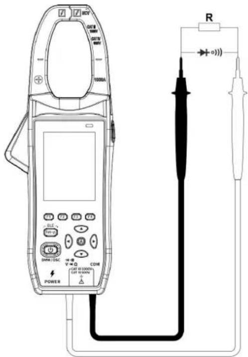
- Read the diode forward bias. If the test lead connection is reversed, the digital clamp meter will display "OL".
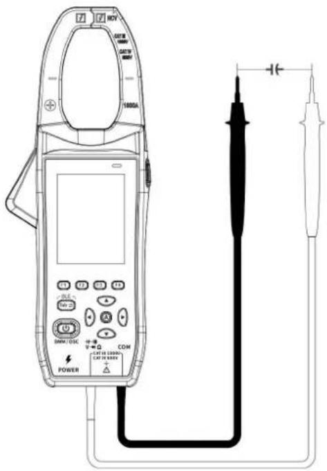
Measuring Capacitance

Caution: To avoid possible damage to the digital clamp meter or equipment under test, disconnect circuit power and discharge all high-voltage capacitors before measuring capacitance. Use the DC voltage function to confirm that the capacitor fully discharged.
- Press F4 to enter capacitance testing mode, Cap will be displayed in the upper left corner.
- Connect the black test lead to the terminal and the red test lead to the terminal.
- Probe the test points to measure the capacitance in the circuit, as shown in the image.
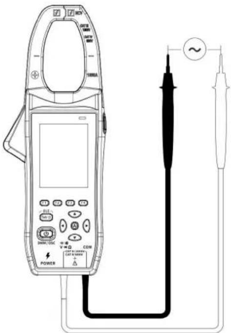
Measuring Frequency
-
Press to enter frequency measurement mode, Freq will be displayed in the upper left corner.
-
Connect the black test lead to the terminal and the red test lead to the terminal.
-
Probe the test points to measure the frequency in the circuit shown in the image.
- Press to the second page menu and press to switch between the frequency and duty cycle measurements.
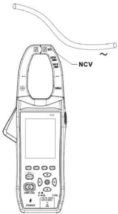
Measuring NCV
-
Press to enter capacitance testing mode, NCV will be displayed in the upper left corner. Bring the front end of the clamp head close to the measured conductor for AC voltage detection.
-
To detect whether there is AC voltage or an electromagnetic field in the area, the LCD will display a dash (-"). The display will indicate four levels based on the voltage detected: “-”, “- -”, “- - -”, and “- - - -”. Additionally, the buzzer will emit a continuous intermittent sound, and the NCV LED will light up. If no voltage is detected, the LCD will display "EF".
Multimeter Features
Setting Scale
- Press to enter automatic gear mode.
- In the automatic gear mode, press or to enter manual gear mode.
Setting Range
- Press to switch into DC current measurement and press

or to up and down measurement scales.
- Press to switch into AC current measurement, press to

the second page menu, press or to select Inrush、Hz/A
function, and then press ▲ or ▼ to up and down measurement scales.
- Press to switch into DC voltage measurement, press to F2
switch into mV, V, and then press on to up and down measurement scales.
- Press to switch into AC voltage measurement, press to F2
switch into mV、V, and press to the second page menu, then
press F4 to select Hz/V function, and then press ▲ or ▼ to up and down measurement scales.
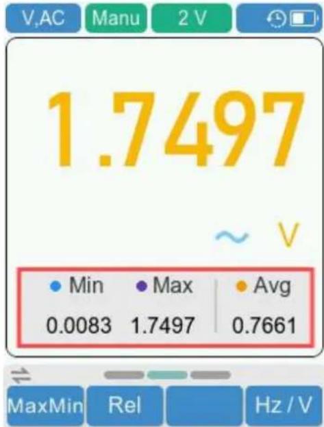
Making Max/Min Measurements
Press Tab switch into the second page menu and press to enter
Max/Min measurement. When the button is pressed, it will automatically enter the manual gear mode. Press the button again to exit the Maxmin mode and resume the automatic gear mode.
other
| Min | Max | Avg | |---|---|---| | 0.0083 | 1.7497 | 0.7661 | | 1.7497 | 1.7497 | 0.7661 |Making Relative Measurements
When making relative measurements, reading is the difference between a stored reference value and the input signal.
- Press Tab switch into the second page menu and press F2 to
enter the relative mode, will be shown on the display. The
measurement value when pressing is stored as the reference
value.In this mode△(current reading) = input value - reference value. 2. Press it again to exit the mode.
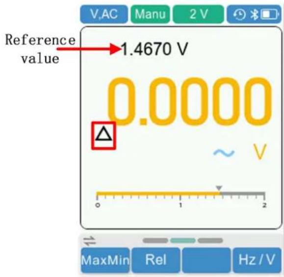
In relative measurement, the manual range mode will be activated automatically (The relative measurement should be carried out under a certain range, that is, this function is only available under the manual range mode.).
Value Hole Mode
The value hold mode keeps the current reading on the display.
-
Press HOLD on the right, the current reading will be maintained, HOLD will be displayed.
-
Press it again to exit the mode.
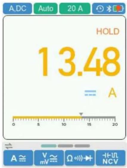
5. How to Use the Oscilloscope
Introduction to the User Interface of the Oscilloscope
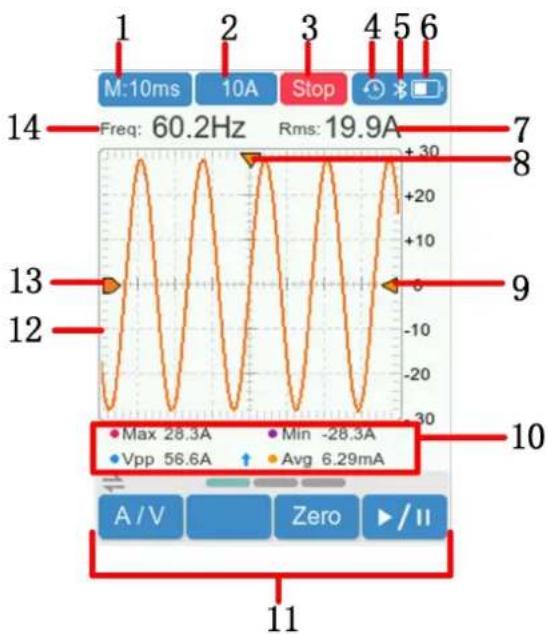
line
| Parameter | Value | | --------- | --------- | | Max | 28.3A | | Min | -28.3A | | Vpp | 56.6A | | Avg | 6.29mA |Figure 5- 1: Oscilloscope Interface
Description:
- Time base display (In the horizontal direction, each grid represents a specific time interval.).
- Scale (In the vertical direction, each grid represents a specific voltage or current value.)
- The trigger status indicates the following information:
Trig: A trigger has been detected and post trigger information is being collected.
Ready: All pre trigger data have been obtained and the oscilloscope is ready.
Scan:Continuously collect and display waveform data.
Stop:Stop collecting waveform data.
-
Automatic shutdown sign: Displays the flag when enabled. Closing will hide the identity.
-
Bluetooth sign: Displays the flag when enabled. Closing will hide the identity.
- Battery power and external power supply indication.
- Rms value.
- Trigger horizontal displacement.
- Trigger level position.
- Measurement value.
- Operation menu.
- Waveform display area.
- Channel waveforms.
- Frequency value.
Measuring System
Automatic Measurement
In oscilloscope mode, it will display automatic measurement value, the screen displays six measurement types in the bottom: Freq, Rms, Max, Min, Vpp and Avg.
The automatic measurement of voltage parameters
The oscilloscopes provide automatic voltage measurements including Avg, Vpp, Rms, Max, Min and Vamp. Figure 5-2 below shows a pulse with some of the voltage measurement points.
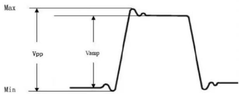
line
| Level | Description | |-------|-----------------| | Max | Upper limit | | Min | Lower limit | | Vpp | Peak-to-peak | | Vamp | Peak-to-peak |Figure 5-2
Avg: The arithmetic mean over the entire waveform.
Vpp: Peak-to-Peak Voltage.
Rms: The true Root Mean Square voltage over the entire waveform.
Max: The most positive peak voltage measured over the entire waveform.
Min: The most negative peak voltage measured over the entire waveform.
Measurement:
-
Press to switch into oscilloscope mode.
-
Press switch into voltage measurement and then press or
to up and down measurement gear, press or can adjust time base gear.
- Press switch into current measurement and then press or
to up and down measurement gear, press or car adjust time base gear.
-
Press F1 switch into current measurement, if there is residual magnetism, press the F3 key to select "Zero." This will temporarily subtract the current residual magnetism from the readings.
-
Press F4 or HOLD in the right. While in pause mode, press or can zoom in or out the waveform.
-
Press Tab to enter the second page menu, press F1 to set the trigger is rise or fall and press F2 or F3 to up and down the trigger level position.
System Settings
Press Tab to enter the third page menu. Press F1\~ F4 can select the desired function menu.
-
Brightness setting: Press F1 the brightness varies between Low, Mid, and High.
-
Automatic shutdown setting: Press F2 to open or close the function.
When the function is turned on, it will automatically shut down after a specified period of time. However, When the function is turned off, manual shutdown is required.
- Theme setting: Press to change the display theme.
How to use Bluetooth
(1) On the mobile device, scan the QR code below and follow the instructions to install the free multimeter app.

(2) Open the installed application on your mobile device.
(3) Turn on the multimeter, press and hold until appear on the display.
(4) Click on "Device List" in the bottom navigation bar.

(5) Click the "+" icon in the upper left corner to begin searching for devices and list out the multimeters found.
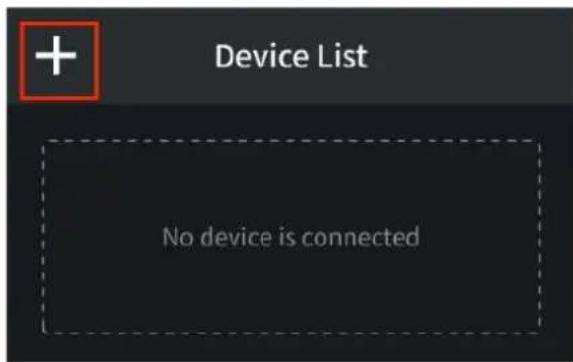
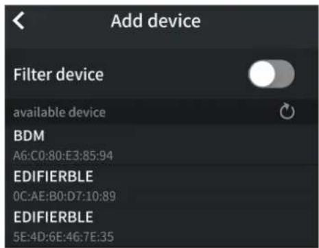
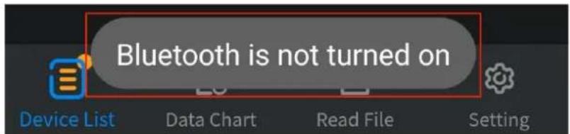
(6) If the Bluetooth of the mobile device is not enabled, a prompt box will pop up at the bottom, indicating "Bluetooth is not turned on". You need to manually open the Bluetooth of the mobile device before connection can be made.
(7) Active "Filter device" to hide incompatible multimeters.
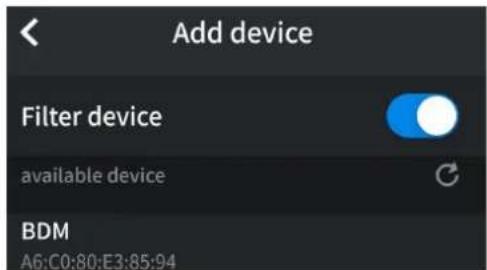
(8) After "BDM" appears in the list of available devices, click and select to connect it to the mobile device.
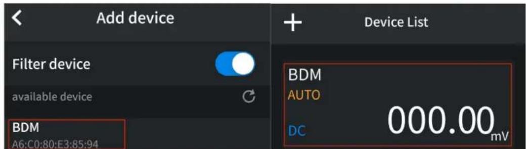
Note: When Bluetooth is enabled, the auto power-off function is disabled. After Bluetooth is turned off, the auto power-off function will be restored.
6. Technical Specifications
Standard conditions: The environment temperature is 18^ C to 28^ C, the relative humidity is less than 80%.
Note:
- When measuring AC voltage, AC current, accuracy guarantee range is 10% to 100% of the range.
- When measuring DC voltage, DC current or capacitance, accuracy guarantee range is 5% to 100% of the range.
Multimeter Specification
| Function | Measurement Range | Resolution | Function | ||
| DC Voltage (V) | mV | 20.000mV | 0.001mV | ±(0.1%+20dig) | |
| 200.00mV | 0.01mV | ±(0.1%+6dig) | |||
| V | 2.0000V | 0.0001V | ±(0.1%+5dig) | ||
| 20.000V | 0.001V | ||||
| 200.00V | 0.01V | ||||
| 1000.0V | 0.1V | ±(0.15%+5dig) | |||
| AC Voltage (V) | mV | 200.00mV | 0.01 mV | VRMSFreq range:40Hz-1000Hz | ±(0.6%+10dig) |
| V | 2.0000V | 0.0001V | |||
| 20.000V | 0.001V | ||||
| 200.00V | 0.01mV | ||||
| 1000.0V | 0.1V | ±(0.8%+10dig) | |||
| DC Current (A) | A | 20.00A | 0.01A | ±(2.0%+10dig) | |
| 200.0A | 0.1A | ±(2.0%+5dig) | |||
| 1000A | 1A | ||||
| AC Current (A) | A | 20.00A | 0.01A | VRMSFreq range:40Hz-1000Hz | ±(3.0%+10dig) |
| 200.0A | 0.1A | ±(2.5%+5dig) | |||
| 1000A | 1A | ||||
| Inrush Current(A) | A | 20.00A | 0.01A | VRMSFreq range:40Hz-1000Hz | ±(10.0%+10dig) |
| 200.0A | 0.1A | ||||
| 1000A | 1A | ||||
| NCV | Support | ||||
| Resistance(Ω) | 200.00Ω | 0.01Ω | ±(0.8%+10dig) | ||
| 2.0000kΩ | 0.0001kΩ | ±(0.3%+10dig) | |||
| 20.000kΩ | 0.001kΩ | ||||
| 200.00kΩ | 0.01kΩ | ||||
| 2.0000MΩ | 0.0001MΩ | ||||
| 20.000MΩ | 0.001MΩ | ±(0.5%+5dig) | |||
| 100.00MΩ | 0.01MΩ | ±(5.0%+10dig) | |||
| Capacitance(F) | 2.000nF | 0.001nF | ±(5.0%+10dig) | ||
| 20.00nF | 0.01nF | ±(3.0%+10dig) | |||
| 200.0nF | 0.1nF | ||||
| 2.000μF | 0.001μF | ||||
| 20.00μF | 0.01μF | ||||
| 200.0μF | 0.1μF | ||||
| 2.000mF | 0.001mF | ||||
| 20.00mF[1] | 0.01mF | ||||
| Frequency [2](Hz) | 200.00Hz | 0.01Hz | ±(0.1%+5dig) | ||
| 2.0000kHz | 0.0001kHz | ||||
| 20.000kHz | 0.001kHz | ||||
| 200.00kHz | 0.01kHz | ||||
| 2.0000MHz | 0.0001MHz | ||||
| 20.000MHz | 0.001MHz | ||||
| Duty Cycle[3](%) | 0.1%-99.9%(Typical:Vrms=1 V,f=100Hz) | 0.10% | ±(1.2%+3dig) | ||
| 0.1%-99.9%(≥1 kHz) | ±(2.5%+10dig) | ||||
| Diode | 3.0000V | 0.0001V | Open circuit voltage 3.2V | ||
| On-Off | 0~200.0Ω | 0.1Ω | Buzzer limit 50Ω; The measurement value is displayed from 00 to 200.0Ω, and "OL" is displayed if the value exceeds. | ||
[1] When measuring capacitance, for the 20.00mF range, the measuring duration should be over 30 seconds.
[2] When measuring frequency, the typical waveform is Square or Sine. The signal meets the following conditions:
| Frequency | Amplitude (rms) |
| 1 Hz – 20 MHz | ≥ 1 V |
[3] When measuring duty cycle, the typical waveform is Square.
Note: when measuring resistance and capacitance, the influence of the resistance reactance of the pen itself on the measured value should be considered.
Oscilloscope Specification
| Characteristics | Instruction |
| Analog bandwidth | Voltage: 1MHzCurrent: 1KHz |
| Sample mode | Real-time sample |
| Real-timesampling rate | 5.0 MSa/s |
| Channel | 1 |
| Input impedance | ≥10 MΩ |
| Maximum input voltage | Maximum peak voltage 1000V |
| Maximum sample current | Maximum peak current 1000A |
| Scan speed | 2.5 us/div - 10 s/div |
| Time base accuracy | ±(0.01 % + 0.1 div) |
| Sensitivity | 30 mV/div - 500 V/div |
| Displacement range | ±3 grid |
| Sensitivity accuracy | ±(5%+0.2div) |
| Measurement value | Rms、Freq、Max、Min、PK-PK、Avg |
| Trigger mode | Auto |
| Trigger type | Rise、Fall |
| Bluetooth communication | A smart phone can be used to view the measurem data of the multimeter on the mobile phone side, perform remote control, display data charts, and sto the measurement data in CSV format. |
| Automatic shutdown | When all functions are not used, the meter will automatically shut down in about 10 minutes.(the default is 10 minutes of automatic shutdown when starting, which can be canceled) |
| True effective value | √ |
| Display mode | DMM or OSC |
| Return zero | √ |
| measurement | |
| Input protection | √ |
| Digital hold | √ |
| Power | Single section 18650 3.7V |
| Low battery display | When the power is low, there will be a low power window, and wait for a period of time to shut down automatically. |
| Backlight function | √ |
| LCD Size | 2.8 inch |
| Weight | Approx. 0.35kg |
| Dimension | 248mm (L) x 94.5mm (W) x 37.8mm (D) |
Interval Period of Adjustment:
One year is recommended for the calibration interval period.
7. Appendix
Appendix A: List of Accessories
- 1 set of probes
- 1 quick guide
● 1 USB-TYPE C line
Appendix B: Maintenance and Cleaning
General maintenance
Do not store or place the instrument in a place where the LCD screen will be exposed to direct sunlight for a long time.
Caution: Do not let spray, liquid or solvent touch the instrument or probe to prevent damage to the instrument or probe.
Cleaning:
Check the instrument and probe frequently according to the operation. Clean the external surface of the instrument as follows:
- Please wipe the floating dust outside the instrument and probe with a soft cloth. When cleaning the LCD, be careful not to scratch the transparent LCD protection screen.
- Wipe the instrument with a damp but non dripping soft cloth. Please disconnect the power supply. It can be scrubbed with soft detergent or water. Do not use any abrasive chemical cleaning agent to avoid damaging the instrument or probe.

Warning: Please make sure the instrument is dry before re-energizing to avoid electrical short circuit or personal injury caused by moisture.
Charging and Replacement of Battery
During the long-term storage of the device, the battery may be too low due to the self-discharge of the lithium battery and the device cannot be turned on. This is a normal phenomenon.
Please use the attached adapter to pre-charge the device for 0.5 to 1 hour (depending on the storage time) before turning it on. In addition, if the device is not used for a long time, it is recommended to charge it at regular intervals to avoid over-discharge of the lithium battery.
Battery Charging
The lithium battery may not be fully charged when delivered. To make the battery be charged, this device has an approximate charging time of 8 hours and a peak discharge battery life of about 18.5 hours. The power supply and battery indicator symbols in the upper right corner of the screen are explained as follows:

symbol indicates the power-on charging status;

symbol indicates battery power supply;

symbol indicates that there is only about five minutes of use time left.
Please charge as soon as possible according to the relevant tips to avoid damage to the battery.
Charging Method
Connect the digital clamp meter to a computer or other equipment through a USB data cable for charging (pay attention to the load capacity of the power supply equipment to avoid abnormal operation of the equipment).
Note
To avoid overheating of the battery during charging, the ambient temperature must not exceed the allowable value given in the technical specifications.
Replacement of Lithium Battery
Generally, the battery does not need to be replaced. However, when necessary, it can only be replaced by qualified personnel, and only lithium batteries of the same specification can be used.
- Oct. 2024 edition V1.0.1
- General Warranty
- Table of Contents
- Safety Information 1
- Quick Start ....5
- Instrument Panel ....7
- How to Use the Multimeter 9
- How to Use the Oscilloscope 25
- Technical Specifications ....30
- Appendix 34
- Safety Information
- General Safety Requirements
- Measurement Category
- Measurement category definition
- Safety Terms and Symbols
- Safety Terms
- Safety Symbols
- Quick Start
- General Inspection
- Check whether there is any damage caused by transportation.
- Check the Accessories
- Check the Complete Instrument
- Install the Battery
- battery type.
- Power on/off
- Selecting the Range
- 3.Instrument Panel
- Front Panel and Keys
- 4.How to Use the Multimeter
- About This Chapter
- Instrument Interface
- Input terminals
- Making Measurements
- Measuring DC or AC Current
- Note:
- Measuring AC or DC Voltage
- Measuring Resistance
- Measuring Continuity
- Measuring Diodes
- Measuring Capacitance
- Measuring Frequency
- Measuring NCV
- Multimeter Features
- Setting Scale
- Setting Range
- Making Max/Min Measurements
- Making Relative Measurements
- Value Hole Mode
- How to Use the Oscilloscope
- Introduction to the User Interface of the Oscilloscope
- Description:
- Measuring System
- Automatic Measurement
- The automatic measurement of voltage parameters
- Measurement:
- System Settings
- How to use Bluetooth
- Technical Specifications
- Interval Period of Adjustment:
- Appendix
- Appendix A: List of Accessories
- Appendix B: Maintenance and Cleaning
- General maintenance
- Cleaning:
- Charging and Replacement of Battery
- Battery Charging
- Charging Method
- Note
- Replacement of Lithium Battery
Brand : Owon
Model : 1000A
Category : Multimeter