
DCU5D - Blender YAMAHA - Free user manual and instructions
Find the device manual for free DCU5D YAMAHA in PDF.


| Product Type | Digital Mixing Console |
| Brand | Yamaha |
| Model | DCU5D |
| Number of Input Channels | 48 (mono) + 4 stereo returns |
| Number of Mix Buses | 24 (variable/fixed) |
| Number of Matrix Buses | 8 |
| Number of Stereo Buses | 2 (Stereo A/B) |
| Number of DCA Groups | 8 |
| Number of Mute Groups | 8 |
| Internal Effects | Up to 8 (configurable with GEQ) |
| Graphic Equalizers (GEQ) | Up to 20 modules |
| Surround Modes | Stereo, 3-1, 5.1, 6.1 |
| Phantom Power | +48V (master switch) |
| Sampling Frequency | 44.1/48 kHz, 88.2/96 kHz |
| Remote Control Software | PM5D Editor / DSP5D Editor via Studio Manager |
| Dimensions (approximate) | 19" rack mount, depth varies (not specified) |
| Weight (approximate) | Varies by configuration; not specified |
| Power Supply | Internal; power consumption not specified |
| Memory | Scene and library storage via session files (.YSE, .PM5) |
| Cleaning | Use a soft dry cloth; avoid liquids and abrasives |
Frequently Asked Questions - DCU5D YAMAHA
User questions about DCU5D YAMAHA
0 question about this device. Answer the ones you know or ask your own.
Ask a new question about this device
Download the instructions for your Blender in PDF format for free! Find your manual DCU5D - YAMAHA and take your electronic device back in hand. On this page are published all the documents necessary for the use of your device. DCU5D by YAMAHA.
USER MANUAL DCU5D YAMAHA
- T he software and this owner's manual are the exclusive copyrights of Yamaha Corporation.
- Copying of the software or reproduction of this manual in whole or in part by any means is expressly forbidden without the written consent of the manufacturer.
- Copying of the commercially available music sequence data and/or digital audio files is strictly prohibited except for your personal use.
- Yamaha makes no representations or warranties with regard to the use of the software and documentation and cannot be held responsible for the results of the use of this manual and the software.
- The screen displays as illustrated in this owner's manual are for instructional purposes, and may appear somewhat different from the screens which appear on your computer.
• Future upgrades of application and system software and any changes in specifications and functions will be announced separately. - Windows is a registered trademark of Microsoft Corporation in the U.S. and other countries.
• Apple, Mac and Macintosh are trademarks of Apple Inc., registered in the U.S. and other countries. - The company names and product names in this Owner's Manual are the trademarks or registered trademarks of their respective companies.
Yamaha Pro Audio Global Site
http://www.yamahaproaudio.com/
Contents
Getting Started 2
INPUT CH window 8
ST IN window.... 11
FX RTN window.... 13
MIX window.... 15
MATRIX window 17
STEREO window 19
DCA window 21
Selected Channel window 22
If an input channel is selected 22
If a MIX channel is selected 31
If a MATRIX channel is selected.... 36
If a STEREO A/B channel is selected.... 37
Patch Editor window.... 40
Surround Editor window.... 45
GEQ window 47
Effect Editor window.... 50
DCA/Mute Group window.... 54
Scene window 57
Library window 66
Meter window....68
Timecode Counter window.... 69
Sync window 69
Preference window 70
User Defined Keys Setup window.... 72
Fader Mode Assign window.... 73
Output Port Att window 73
Word Clock window.... 74
Oscillator window 77
Cue/Solo window....79
Port Trim window 82
Keyboard Shortcuts.... 83
Index......84
* Specifications and descriptions in this owner's manual are for information purposes only. Yamaha Corp. reserves the right to change or modify products or specifications at any time without prior notice. Since specifications, equipment or options may not be the same in every locale, please check with your Yamaha dealer.
| Term Definition | |
| Studio Manager | refers to Studio Manager V2 |
| PM5D Editor | refers to PM5DV2 EditorThis editor works with PM5DV2. Make sure that the console’s firmware has been updated to V2. |
Description of menus and buttons
In the event that menu and button names on a Windows system are different from those on a Mac, this manual uses the Windows menu and button names followed by the Mac menu and button names in parentheses.
Getting Started
What is PM5D/DSP5D Editor?
PM5D Editor and DSP5D Editor allow you to remotely control the parameters of the PM5D or DSP5D, and save the parameters on your computer.
PM5D/DSP5 Editor are used by starting them up from within Studio Manager. To use PM5D/DSP5D Editor, you must perform the following steps.
"Start up Studio Manager and make settings" → "Start up PM5D Editor or DSP5D Editor and make settings" → "Synchronize with the PM5D/DSP5D itself (→ p.5)"
NOTE For details on operations in Studio Manager, refer to the Studio Manager operating manual.
Settings in PM5D/DSP5D Editor
You will need to set the following items individually for each editor that is open.
NOTE
- Before you make the following settings, you must select the MIDI ports in the Setup window of Studio Manager.
- To start up PM5D Editor or DSP5D Editor in the Setup window of Studio Manager, double-click the corresponding icon in the Studio Manager window.
PM5D Editor: System Setup
To open the System Setup window, choose the [File] menu item [System Setup]. You must specify the Input port and the Output port.
Input port/Output port: From the ports you have previously specified in Studio Manager, select the ports you will use for communication with the PM5D.
Console Device ID: PM5D Editor can control the desired single unit chosen from a maximum of eight units that each have their own ID. Select the ID of the unit you want to control.
Fast Sync: This shortens the synchronization time with the PM5D itself. If synchronization fails, clear this check box.
Level Meter: This specifies whether level meter data will be included in the communication with the PM5D itself. If this check box is selected, level meter data from the PM5D will be received, but the response speed may be slower. If you feel that the response is slow, clear this check box.
System Color: You can change the workspace color of PM5D Editor. Choose one of eight colors from the pulldown menu. This is convenient when you need to distinguish between multiple instances of PM5D Editor.
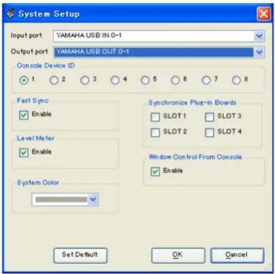
Synchronize Plug-in Boards: If these option boxes are selected, the data of the Y96K plug-in board installed in the corresponding slot will be synchronized along with the scene data.
Window Control from Console: PM5D Editor windows can be opened or closed remotely from the PM5D itself by using user-defined keys. This option enables remote control.
Set Default: By clicking this button, you can store the current System Setup settings as the default values for PM5D Editor.
□DSP5D Editor: System Setup
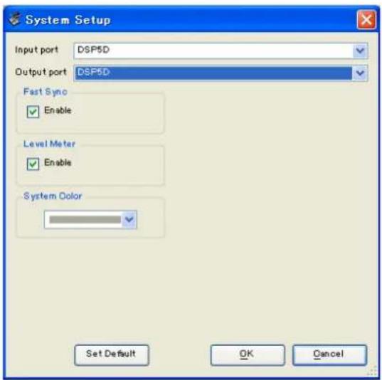
To open the System Setup window, choose [System Setup] from the [File] menu. You must specify the Input port and Output port.
Input port/Output port: From the ports you have previously specified in Studio Manager, select the ports you will use for communication with the DSP5D.
Fast Sync: This shortens the time required for synchronization with the DSP5D. If synchronization fails, you should disable (clear) this item.
Level Meter: This specifies whether level meter data will be included in the communication with the DSP5D. If this check box is selected, level meter data from the DSP5D will be received, but the response speed may be slower. If you feel that the response is slow, clear this check box.
System Color: You can change the workspace color of DSP5D Editor. Choose one of eight colors from the pulldown menu. This is convenient when you need to distinguish between multiple instances of DSP5D Editor.
Set Default: By clicking this button, you can store the current System Setup settings as the default values for DSP5D Editor.
Mixer Setup
To open the Mixer Setup window, choose [Mixer Setup] from the [File] menu.
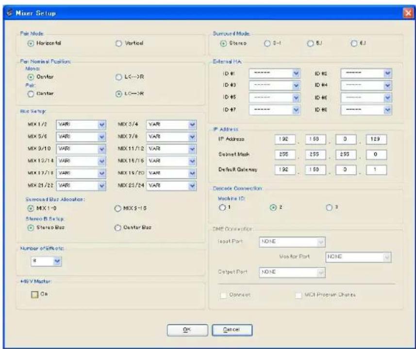
Pair Mode: Select whether faders will be paired Horizontally or Vertically.
Pan Nominal Position: Select whether the signal will be at nominal level when panned to the center (Center) or when panned all the way to left or right (L<-->R). You can make separate settings for monaural channels and paired channels.
Bus Setup: Select the MIX bus mode (VARI/FIXED) for every two adjacent odd-numbered/even-numbered MIX buses. MIX buses assigned as surround buses are indicated as “SURROUND” and cannot be changed.
Surround Bus Allocation: Select the MIX buses (MIX 1–8 or MIX 9–16) that will be used as surround buses.
Stereo B Setup: Specify whether the same signal as the STEREO A bus will be sent to the STEREO B bus (Stereo Bus), or whether the STEREO B bus will function as the CENTER bus for LCR mode (Center Bus).
Number of Effects: This changes the number of assigned internal effects and GEQ modules. Decreasing the number of internal effects by one will increase the number of available GEQ modules by one. You can change the number assigned between eight internal effects (and twelve GEQ modules) to no internal effects (and twenty GEQ modules). You can use up to eight GEQ modules as effects.
+48V Master: This function is found only in DSP5D Editor. It is the master switch for the phantom power (+48V) supplied to INPUT jacks 1–48 and ST IN jacks 1–4. If this switch is off, phantom power will not be applied, regardless of whether the +48V shown in the display is on or off.
Surround Mode: Select the surround mode (STEREO, 3-1, 5.1, 6.1).
External HA: This specifies the connection ports for external HA (AD8HR) units connected via the slots. External HA units are assigned an ID of 1–8 (1–4 on the DSP5D), and here you can select the ports to which each will be connected.
IP Address: This function is found only in DSP5D Editor. You can specify the IP Address, Subnet Mask, and Default Gateway values. If the DSP5D and computer are connected in a one-to-one correspondence, we recommend that you use the following default values.
• IP Address...... 192.168.0.129
- Subnet Mask 255.255.255.0
- Default Gateway...... 192.168.0.1
NOTE
- For details on network settings for your computer, refer to DME-N Network Driver installation guide for DSP5D(Windows) or Network-MIDI Driver installation guide(Mac).
- If you changed the IP Address, you must close DSP5D Editor and Studio Manager, and re-specify the IP Address values for the DME-N Network Driver communication port or the Network-MIDI Driver communication port. The connection between the DSP5D and DSP5D Editor will be broken when you change the IP Address
Cascade Connection: This function is found only in DSP5D Editor. It specifies the Cascade Machine ID when using a cascade connection. If this is set to 1, you will be able to make DME Connection settings. If this is set to 2 or 3, the Cascade setting will be Slave, and you won't be able to make DME Connection settings.
DME Connection: This function is found only in DSP5D Editor. This is a setting for connecting the DSP5D with a DME series unit (except the DME32). For details on the connection method, refer to the Global function MIDI Remote Function section in the reference section of the DSP5D manual.
NOTE
Even if you enable DME Connection, remote control of the DME cannot be performed from DSP5D Editor. Use the separate DME Designer to remotely control the DME.
- Input Port / Output Port
This specifies the DSP5D's connector/slot to which the DME is connected. You can choose SLOT1, SLOT2, CASCADE IN/OUT D-SUB, or CASCADE OUT RJ-45.
NOTE
- If you select CASCADE IN/OUT D-SUB or CASCADE OUT RJ-45, the Slot display area of Patch Editor will show the selected connector/slot.
- Since CASCADE IN RJ-45 cannot be used, you must connect the DSP5D via its CASCADE OUT RJ-45 connector if you use an Ethernet cable to connect the DME and DSP5D.
- Monitor Port
This specifies the DSP5D port that will receive monitor signals from the DME. You can select stereo channels from within the port selected by Input Port.
- Connect
This initiates or ends communication between the DSP5D and DME. Communication will begin if this check box is selected, and will end if this check box is cleared. The actual start or end of communication will occur when you click the OK button.
• MIDI Program Change
This allows the DME to recall a scene according to the Program Change Table assignment in synchronization with scene recall that occurs on the DSP5D. If you enable this function by selecting the check box, synchronization via MIDI program change will be enabled. In order to enable this function, the Connect check box must be selected.
Synchronizing PM5D/DSP5D Editor
When PM5D/DSP5D Editor starts up, the parameter settings on the PM5D/DSP5D itself and the parameter settings in PM5D/DSP5D Editor may be different. Therefore, you must first match the parameter settings on the PM5D/DSP5D itself with those in PM5D/DSP5D Editor. This operation is called “synchronization.” Follow the steps below to synchronize PM5D/DSP5D Editor.
1 Select [Synchronize], then [Re-synchronize].
The window shown at right opens.
2 Select whether you want to transfer your settings to PM5D/DSP5D Editor, or vice versa.
At this time, the All Libs option determines whether or not Scene and Library data is synchronized.
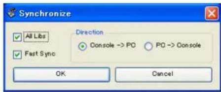
If the [Fast Sync] check box is selected, synchronization with the unit itself will be faster. In order to enable this item, you must select the [Fast Sync] check box in the System Setup window.
PC -> Console (DSP5D): Transfers the current parameter settings in PM5D/DSP5D Editor to the PM5D/DSP5D itself.
Console (DSP5D) -> PC: Transfers the current parameter settings of the PM5D/DSP5D itself to the PM5D/DSP5D Editor.
3 Click [OK].
![YAMAHA DCU5D - Click [OK]. - 1](/content/2026/05/910394/images/21bdecfcd91aabc53dc10fa88a04dd4d5282723d0ada170c8256775517213e9d.jpg)
Do not operate the PM5D/DSP5D itself while synchronization is in progress.
NOTE
- When you synchronize with Studio Manager, synchronize will occur between all editors selected in Studio Manager and the respective hardware units.
- If loading of scene data from an external location is disabled on the unit itself, the Direction will be set to Console (DSP5D) -> PC. If there is scene data that is set to Read Only, a dialog box will appear when you click OK, asking whether you want the read-only data to be synchronized as Console (DSP5D) -> PC, or not synchronized. Your selection will apply to all scene data that is set to Read Only.
Offline Edit Function
If you do not want to synchronize PM5D/DSP5D itself with PM5D/DSP5D Editor, select [Offline Edit] from the [Synchronization] menu. To apply your off-line edits to the PM5D/DSP5D itself, select [Re-Synchronize] from the [Synchronization] with the PC -> Console (DSP5D) option to synchronize the PM5D/DSP5D itself with PM5D/DSP5D Editor.
The Offline Edit function is also activated when you click the [ONLINE]/[OFFLINE] button in the Sync window.
NOTE
Some effect parameters in the PM5D/DSP5D itself change their displayed values depending on the sampling frequency. If you switch PM5D/DSP5D Editor from OFFLINE to ONLINE, displayed parameter values may change because PM5D/DSP5D Editor loads the sampling frequency from the PM5D/DSP5D itself and updates the display.
Working with Sessions
In PM5D/DSP5 Editor, mix settings for an entire PM5D/DSP5D unit, including scene and library data, are called a Session.
| Creating a new Session | Choose [New Session] from the [File] menu. |
| Opening a previously saved Session | Choose [Open Session] from the [File] menu. |
| Saving the current Session | Choose [Save Session] from the [File] menu. |
| Saving the current Session with a new name | Choose [Save Session As...] from the [File] menu. |
When you save a session in the window of an editor, the settings of only that editor will be saved in a file. Session files saved by PM5D/DSP5D Editor have a filename extension of “.YSE”. Files in which only the PM5D itself data is saved (filename extension “.PM5”) can also be handled, allowing you to use a memory card to exchange data with the PM5D itself.
If you save a Session in the Studio Manager window, all selected Editor settings are saved in a file with a file extension of ".YSM."
NOTE
Data with the extension ".PM5" that was saved by PM5D version 1 and PM5D Editor (supporting version 1) can also be opened by PM5DV2 Editor.
Window operations
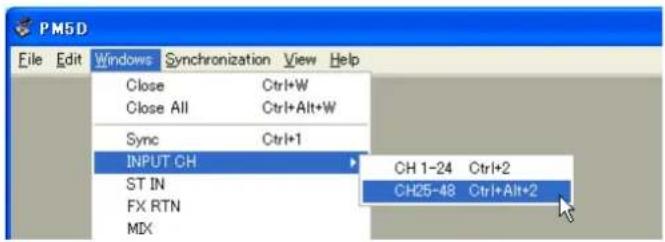
You can select and open each window from the [Windows] menu. For the INPUT CH window and Effect Editor window, use the sub-menu to select the channels or library you want to see.
In the Library window or Scene window, click the tabs located at the top of the window to switch between pages.
![Library OUTPUT CH NO FILE OPEN CLOSE SAVE SAVE AS... No. TITLE PROTECT 001 [ No Data] No. TIT 000 Init](/content/2026/05/910394/images/8101544075e6944daaa2b6fa55ccc4782a3ecce8870004883e12564f1baafe9a.jpg)
Edit functions
☐ Ch Copy / Ch Paste (channel copy / channel paste) function
The Ch Copy/Ch Paste function copies or pastes the channel that is selected by the [SELECT] button (or [SEL] key.) Copy can also be executed by using the keyboard's
Since the Undo data is cleared when you execute Ch Paste, Undo will become unavailable at that point.
☐ Ch Move (channel move) function
The Ch Move function moves the specified channel to the location of another channel that has the same structure.
When you select Ch Move, the dialog box shown at the right will appear. When you click the buttons located below Source and Destination, a channel list will appear.
Select the move Source and move Destination, and click the OK button to move the channel.
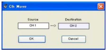
The channels affected by Ch Move will be the same set of channels as selected by [SELECT] button (or [SEL] key). This is not available for output channels. Undo data will be cleared when you execute Ch Move, so all Undo operations will become unavailable at that point.
NOTE
- If the Source is a paired channel, the channels will be moved as a pair.
- If there are paired channels between the Source and Destination, movement occurs in pairs (units of two channels).
- Movement will occur in pairs (units of two channels) if parameters of which there is one instance for every two channels are turned on (also if parameters such as GANG or LINK are on).
In PM5D/DSP5D Editor, you can cancel the latest operation (Undo) and also cancel the cancellation of the latest operation (Redo). If you perform an Undo operation twice in a row, you can cancel the two most-recent operations. If you perform an Undo operation three times in a row, you can cancel the three most-recent operations. In this way, you can cancel multiple recent operations.
The following table describes how to use the Undo/Redo function.
| Undo | Choose [Undo] from the [Edit] menu. |
| Redo | Choose [Redo] from the [Edit] menu. |
Please note, however, that after you perform one of the following operations, you cannot successfully undo or redo any previous operation:
- O perations on the PM5D/DSP5D itself
- Quitting Studio Manager
• C hanging the surround mode or pair mode
• S synchronizing with the PM5D/DSP5D itself - Session operations
• T he GEQ [EQ FLAT] button - M oving the fader positions by changing the GEQ variable width
NOTE You cannot Undo or Redo the following operations:
• Edits in the Setup window
- Synchronization
- Opening and closing the windows
- Resizing the windows
- Ch Copy/Ch Paste
- Ch Move
For some functions, there are also other operations that cannot be undone.
NOTE For Library and Scene operations, Undo/Redo will apply only to the single preceding operation. You cannot undo an operation that occurred two or more operations previously. Undo/Redo in these windows can be performed only using the [UNDO] button in the respective window. Even if you execute a scene recall from the Sync window, you cannot use a shortcut or menu operation to undo this.
Other Functions
☐ Resetting to the default value (Ctrl (⌘ + click)
Move the cursor to a control or a parameter value, then hold down the
Ctrl (⌘ +Shift+Click
Move the cursor to a fader or AUX Send control, then hold down the
INPUT CH window
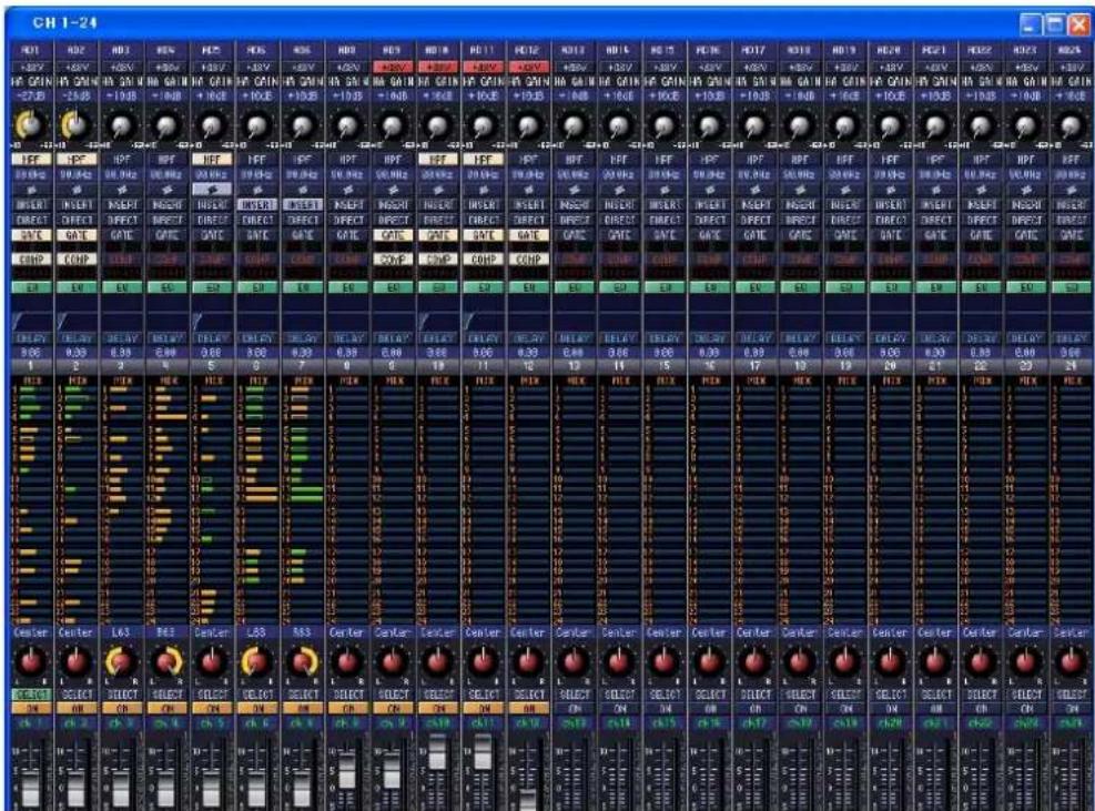
This window displays the parameters of input channels 1–24 or 25–48. The window shows either the channel 1–24 layer or the channel 25–48 layer. To open the other layer's window, choose the [Windows] menu command [INPUT CH] and choose "CH1-24" or "CH25-48."
You can use the [View] menu to choose the parameters that will be displayed in the window.
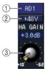
① Input patch
Here you can select an input source to assign to the input channel, from the following choices.
| NONE No assignment | |
| AD1-AD48 INPUT jacks 1-48 | |
| AD1L-AD4R L/R channels of ST IN jacks | 1-4 |
| S1-1, S1-2...S4-15, S4-16 | Input channels of an I/O card installed in slots 1-4On the DSP5D, SLOT3 and SLOT4 are assigned to CASCADE IN/OUT D-SUB. |
| FX1L, FX1R...FX8L, FX8R L/R outputs of | internal effects 1-8 |
| 2TR D1L, 2TR D1R...2TR D3L, 2TR D3R | L/R channels of 2TR IN DIGITAL jacks 1-3* |
| 2TR A1L, 2TR A1R, 2TR A2L, 2TR A2R | L/R channels of 2TR IN ANALOG jacks 1/2* |
* These choices are shown only in PM5D Editor.
② +48V
Switches on/off the phantom power (+48V) of the internal HA (PM5D-RH model and DSP5D only) or of the external HA (AD8HR, AD824) patched to the input channel.
③ HA GAIN
Drag the knob in the screen to adjust the gain of the internal HA (PM5D-RH model and DSP5D only) or of the external HA (AD8HR, AD824) patched to the input channel.

④ HPF (High Pass Filter)
Switches the high pass filter on/off. You can drag the numeric value up or down to edit the cutoff frequency.
⑤ ∅ (Phase)
Inverts the phase of the signal after AD conversion.
⑥ INSERT
Switches the INSERT PATCH path between enabled/disabled.
⑦ DIRECT
Switches the output to the DIRECT OUT PATCH port between enabled/disabled.
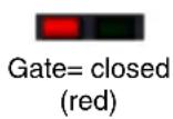
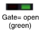
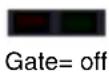
⑧ GATE
Turns the gate on/off. The indicator immediately below the button shows the gate's on/off setting and the open/closed status.
⑨ COMP (Compressor)
Switches the compressor on/off. When the compressor is on, the GR meter immediately below the button shows the amount of gain reduction.
⑩ EQ (Equalizer)
Switches the EQ on/off. The graph immediately below the button shows the approximate response of the EQ. You can drag within the graph to edit the response of the EQ. To reset the EQ to flat response, hold down the
⑪ DELAY
Switches the delay on/off. You can also edit the delay time by dragging the numeric value located immediately below the button up or down
⑫ Channel number
Indicates the input channel number corresponding to this module. You can double-click this number to open the Selected Channel window for this channel. If you hold down your computer keyboard's
⑬ MIX SEND
The bar graphs in this area indicate the send levels of the signals sent from the input channel to MIX buses. You can also adjust the send levels by dragging a bar graph to left or right.
The bar graph display will change according to the send position (pre/post) and on/off status of the signal sent from the input channel to the MIX buses.

Pre/on (green)

Pre/off (green)

Post/on (yellow)

Post/off (yellow)
NOTE
- Y ou can turn this on/off by clicking the number at the left.
- F or FIXED-type MIX buses, the bar graph is fixed at nominal level (0 dB), and only the on/off status is shown.
14 PAN
Sets the panning of the signal sent from the input channel to the STEREO bus. This may be BALANCE depending on the PAN mode.
⑮ SELECT
Selects input channel for which you want to perform operations. This is linked with the INPUT channel strip [SEL] keys on the PM5D panel.
⑯ CH ON (Channel on) button
Switches the input channel on/off. This is linked with the INPUT channel strip CH [ON] keys on the PM5D panel.
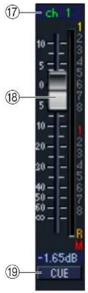
⑰ Channel name
This is a text box that displays the channel name. You can also edit the channel name in this text box.
Note that while the channel number (⑫) does not change when you switch pairing mode in the Mixer Setup window, the channel name display will change according to the pairing mode.
For example if the CH1-24 layer is displayed, and you switch the pairing mode from Horizontal to Vertical, the channel name indications that had been arranged in the order of channels 1, 2, 3 ... 24, 25 will change to the order of 1, 3, 5 ... 45, 47.
⑱ Fader
Adjusts the input level of the input channel. This is linked with the INPUT channel strip faders on the PM5D panel.
The current fader value is shown in the numeric box immediately below the fader. The level meter at the right of the fader shows the level of the input signal.
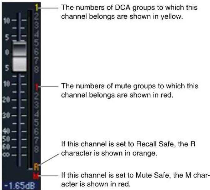
The numbers and alphabetical letters at the right of the fader indicate the DCA group and mute groups to which that channel belongs, and show the Recall Safe and Mute Safe status of the channel.
⑲ CUE
This button cue-monitors the signal of the input channel. This is linked with the INPUT channel strip [CUE] keys on the PM5D panel. If SOLO is active, this will function as SOLO.
ST IN window
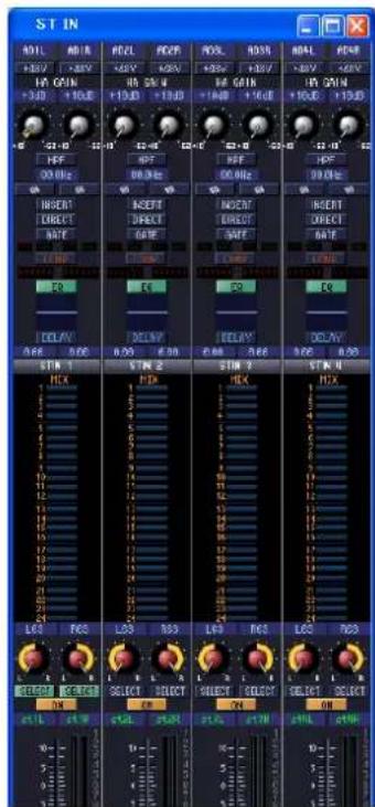
In this window you can view and edit the parameters of ST IN channels 1–4. You can use the [View] menu to choose the parameters that will be displayed in the window.
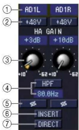
① Input patch Selects the input source that will be assigned to the ST IN channel. The input sources that can be assigned are the same as for an input channel ( p.8).
② +48V Switches on/off the phantom power (+48V) of the internal HA (PM5D-RH model and DSP5D only) or of the external HA (AD824, AD8HR) patched to the ST IN channel.
③ HA GAIN Drag the knob in the screen to adjust the gain of the internal HA (PM5D-RH model and DSP5D only) or of the external HA (AD824, AD8HR) patched to the ST IN channel.
④ HPF (High Pass Filter) Switches the high pass filter on/off. You can drag the numeric value up or down to edit the cutoff frequency.
⑤ ∅ (Phase) Inverts the phase of the signal after AD conversion.
⑥ INSERT Switches the INSERT PATCH path between enabled/disabled.
⑦ DIRECT Switches the output to the DIRECT OUT PATCH port between enabled/disabled.

⑧ GATE Tums the gate on/off. The indicator immediately below the button shows the gate's on/off setting and the open/closed status ( p.9).
⑨ COMP (Compressor) Switches the compressor on/off. When the compressor is on, the GR meter immediately below the button shows the amount of gain reduction.
⑩ EQ (Equalizer)
Switches the EQ on/off. The graph immediately below the button shows the approximate response of the EQ. You can drag the graph to edit the response of the EQ, or hold down the
⑪ DELAY Switches the delay on/off. You can also edit the delay time by dragging the numeric value located immediately below the button up or down
⑫ Channel number
This is the number of the ST IN channel for this module. You can double-click this number to open the Selected Channel window for this channel. If you hold down your computer keyboard's
⑬ MIX SEND The send levels of the signals sent from the ST IN channel to the MIX buses are shown as bar graphs. You can also adjust the send levels by dragging a bar graph to left or right. The bar graph display will change according to the send position (pre/post) and on/off status of the signal sent from the ST IN channel to the MIX buses (→ p.9).
⑭ PAN Specifies the panning of the signal sent from the ST IN channel to the STEREO bus. (You can set L and R separately.) This may be BALANCE depending on the PAN mode.
⑮ SELECT Selects the ST IN channel for which you want to perform operations. (L and R can be selected separately.) This is linked with the ST IN channel strip [SEL] keys on the PM5D panel.
⑯ CH ON (Channel on) button Switches the ST IN channel on/off. This is linked with the ST IN channel strip CH [ON] keys on the PM5D panel.
⑰ Channel name This is a text box that displays the channel name. You can also edit the channel name in this text box.
⑱ Fader Adjusts the input level of the ST IN channel. This is linked with the faders of the ST IN channel strip on the PM5D panel.
The numbers and alphabetical letters at the right of the fader indicate the DCA group and mute groups to which that channel belongs, and show the Recall Safe and Mute Safe status of the channel ( p.10).
⑲ CUE This button cue-monitors the signal of the ST IN channel. This is linked with the ST IN channel strip [CUE] keys on the PM5D panel. If SOLO is active, this will function as SOLO.
FX RTN window
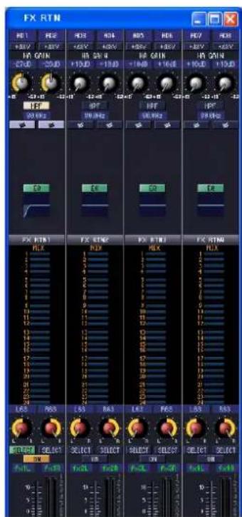
In this window you can view and edit the parameters of FX RTN channels 1–4. You can use the [View] menu to choose the parameters that will be displayed in the window.
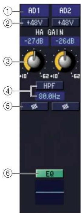
① Input patch
Selects the input source that will be assigned to the FX RTN channel. The input sources that can be assigned are the same as for an input channel ( p.8).
② +48V
Switches on/off the phantom power (+48V) of the internal HA (PM5D-RH model and DSP5D only) or of the external HA (AD8HR, AD824) patched to the FX RTN channel.
③ HA GAIN
Drag the knob in the screen to adjust the gain of the internal HA (PM5D-RH model and DSP5D only) or of the external HA (AD8HR, AD824) patched to the FX RTN channel.
④ HPF (High Pass Filter)
Switches the high pass filter on/off. You can drag the numeric value up or down to edit the cutoff frequency.
⑤ ∅ (Phase)
Inverts the phase of the signal after AD conversion.
⑥ EQ (Equalizer)
Switches the EQ on/off. The graph immediately below the button shows the approximate response of the EQ. You can drag the graph to edit the response of the EQ, or hold down the

⑦ Channel number
This is the number of the FX RTN channel for this module. You can double-click this number to open the Selected Channel window for this channel. If you hold down your computer keyboard's
⑧ MIX SEND
The send levels of the signals sent from the FX RTN channel to the VARI-type MIX buses are shown as bar graphs (the L/R settings are linked). You can also adjust the send levels by dragging a bar graph to left or right.
The bar graph display will change according to the send position (pre/post) and on/off status of the signal sent from the FX RTN channel to the MIX buses ( p.9).
⑨ PAN
Specifies the panning of the signal sent from the FX RTN channel to the STEREO bus. (You can set L and R separately.) This may be BALANCE depending on the PAN mode.
⑩ SELECT
Selects the FX RTN channel for which you want to perform operations. (L and R can be selected separately.) This is linked with the FX RTN channel strip [SEL] keys on the PM5D panel.
⑪ CH ON (Channel on) button
Switches the FX RTN channel on/off. This is linked with the FX RTN channel strip CH [ON] keys on the PM5D panel.
⑫ Channel name
This is a text box that displays the channel name. You can also edit the channel name in this text box.
⑬ Fader
Adjusts the input level of the FX RTN channel. This is linked with the faders of the FX RTN channel strip on the PM5D panel.
The numbers and alphabetical letters at the right of the fader indicate the DCA group and mute groups to which that channel belongs, and show the Recall Safe and Mute Safe status of the channel ( p.10).
⑭ CUE
This button cue-monitors the signal of the FX RTN channel. This is linked with the FX RTN channel strip [CUE] keys on the PM5D panel. If SOLO is active, this will function as SOLO.
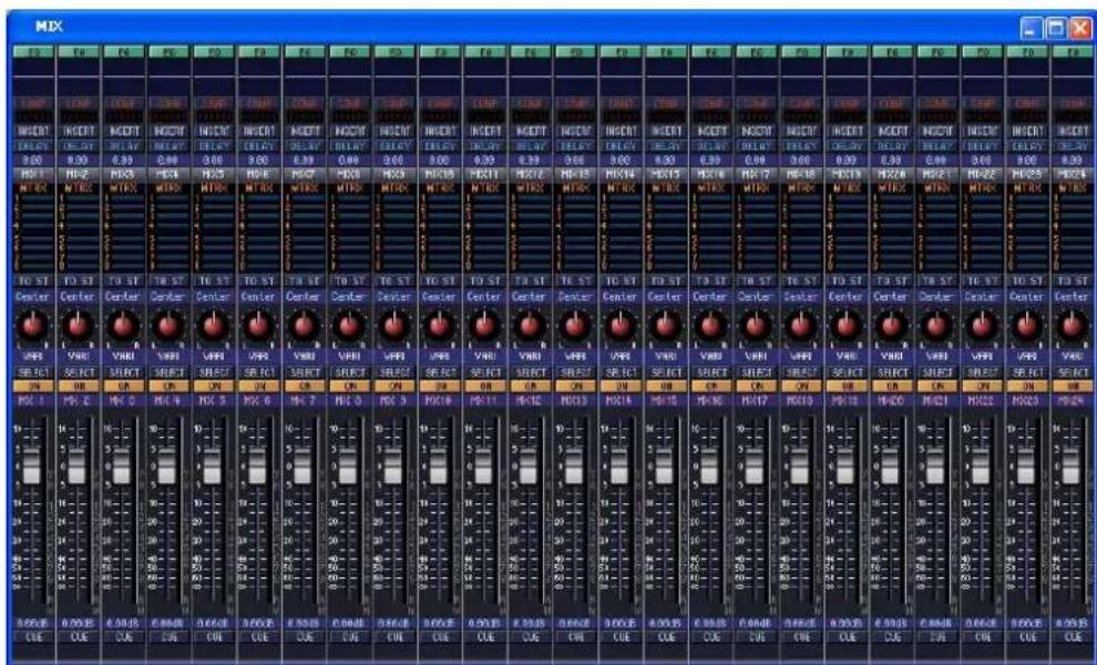
In this window you can view and edit the parameters of MIX channels 1–24. You can use the [View] menu to choose the parameters that will be displayed in the window.
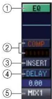
① EQ (Equalizer)
Switches the EQ on/off. The graph immediately below the button shows the approximate response of the EQ. You can drag the graph to edit the response of the EQ, or hold down the
② COMP (Compressor)
Switches the compressor on/off. When the compressor is on, the GR meter immediately below the button shows the amount of gain reduction.
③ INSERT
Switches the INSERT PATCH path between enabled/disabled.
④ DELAY
Switches the delay on/off. You can also edit the delay time by dragging the numeric value located immediately below the button up or down
⑤ Channel number
Indicates the number of the MIX channel corresponding to this module. You can double-click this number to open the Selected Channel window for this channel. If you hold down your computer keyboard's

⑥ MTRX (Send level to MATRIX buses)
These bar graphs indicate the send levels of the signals sent from the MIX channel to each MATRIX bus. You can also adjust the send levels by dragging a bar graph to left or right.
The bar graph display will change as follows according to the send position (pre/post) and on/off status of the signal sent from the MIX channel to the MATRIX buses.
Pre/on (green)

Pre/off (green)

Post/on (yellow)

Post/off (yellow)
NOTE You can turn this on/off by clicking the number at left.
⑦ TO ST (To STEREO)
This is an on/off switch for the signal sent from the MIX channel to the STEREO bus.
⑧ PAN
Sets the panning of the signal sent from the MIX channel to the STEREO bus.
⑨ VARI/FIXED
Indicates the type (VARI or FIXED) of the currently selected MIX bus. (This parameter is for display only. If you want to switch between VARI/FIXED from within PM5D/DSP5D Editor, use the Mixer Setup window ( p.3)
If surround mode is enabled, MIX buses that are assigned as surround buses are displayed with the name of the surround channel (L, R, Ls, Rs ...), and the other MIX buses are displayed as “FIXED.”
⑩ SELECT
Selects the MIX channel for which you want to make settings. This is linked with the MIX [SEL] keys in the MIX section of the PM5D panel.
⑪ ON
Switches the MIX channel on/off.
⑫ Channel name
This is a text box that indicates the channel name. You can also edit the channel name within this text box.
⑬ Fader
Adjusts the output level of the MIX channel. The current fader value is shown in the numeric box immediately below the fader. The level meter at the right of the fader shows the output level of the signal.
The numbers and alphabetical letters at the right of the fader indicate the DCA group and mute groups to which that channel belongs, and show the Recall Safe and Mute Safe status of the channel. (For the significance of the numbers and alphabetical letters, see p.10).
⑭ CUE
This button cue-monitors the signal of the MIX channel. This is linked with the MIX [CUE] keys in the MIX section of the PM5D panel. If SOLO is active, this will function as SOLO.
MATRIX window
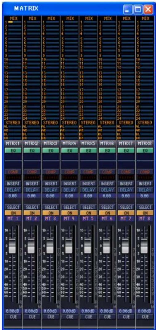
In this window you can view and edit the parameters of MATRIX channels 1–8. You can use the [View] menu to choose the parameters that will be displayed in the window.

① MIX (Send levels from the MIX channels to the MATRIX bus)
Here you can view and edit the send levels of the signals sent from each MIX channel to the MATRIX bus. The method of operation and the meaning of the display are the same as for (⑥) MTRX in the MIX window ( p.16).
② STEREO (Send levels from the STEREO channels to the MATRIX bus)
Here you can view and edit the send levels of the signals sent from the STEREO A/B channels to the MATRIX bus. The method of operation and the meaning of the display are the same as for (⑥) MTRX in the MIX window ( p.16).
③ Channel number
Indicates the number of the MATRIX channel corresponding to this module. You can double-click this number to open the Selected Channel window for this channel. If you hold down your computer keyboard's
④ EQ (Equalizer)
Switches the EQ on/off. The graph immediately below the button shows the approximate response of the EQ. You can drag the graph to edit the response of the EQ, or hold down the
⑤ COMP (Compressor)
Switches the compressor on/off. When the compressor is on, the GR meter immediately below the button shows the amount of gain reduction.
⑥ INSERT
Switches the INSERT PATCH path between enabled/disabled.
⑦ DELAY
Switches the delay on/off. You can also edit the delay time by dragging the numeric value located immediately below the button up or down
⑧ SELECT
Selects the MATRIX channel for which you want to make settings. This is linked with the MATRIX [SEL] keys in the MATRIX section of the PM5D panel.
⑨ ON
This switches the MATRIX channel on/off. This is linked with the MATRIX [ON] keys in the MATRIX section of the PM5D panel.
⑩ Channel name
This is a text box that indicates the channel name. You can also edit the channel name within this text box.
⑪ Fader
This adjusts the output level of the MATRIX channel. The current fader value is shown in the numeric box immediately below the fader. The level meter at the right of the fader shows the output level of the signal.
The numbers and alphabetical letters at the right of the fader indicate the DCA group and mute groups to which that channel belongs, and show the Recall Safe and Mute Safe status of the channel. (For the significance of the numbers and alphabetical letters, see p.10).
⑫ CUE
This button cue-monitors the signal of the MATRIX channel. This is linked with the MATRIX [CUE] keys in the MATRIX section of the PM5D panel. If SOLO is active, this will function as SOLO.
STEREO window
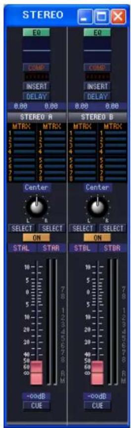
In this window you can view and edit the parameters of the STEREO A/B channels. You can use the [View] menu to choose the parameters that will be displayed in the window.
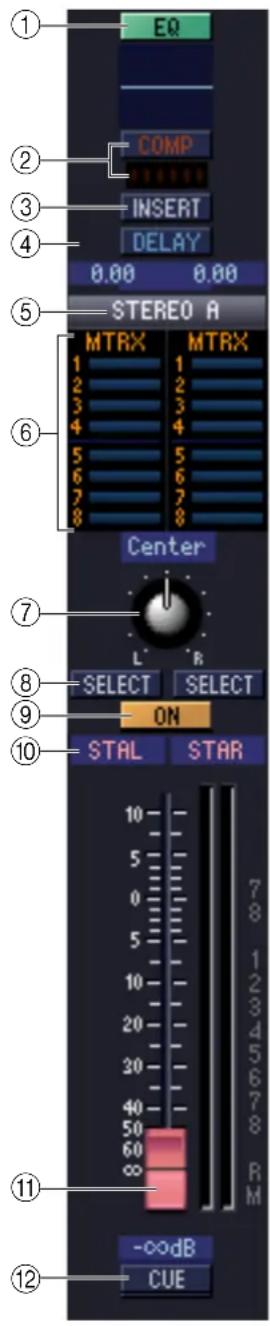
① EQ (Equalizer)
Switches the EQ on/off. The graph immediately below the button shows the approximate response of the EQ. You can drag the graph to edit the response of the EQ, or hold down the
② COMP (Compressor)
Switches the compressor on/off. When the compressor is on, the GR meter immediately below the button shows the amount of gain reduction.
③ INSERT
Switches the INSERT PATCH path between enabled/disabled.
④ DELAY
Switches the delay on/off. You can also edit the delay time by dragging the numeric value located immediately below the button up or down. If GANG is turned on, the L/R delay time will be linked while maintaining their offset value. If GANG is off, the L/R delay times can be edited individually.
⑤ Channel number
This is the channel number (STEREO A or B) of this module. You can double-click this number to open the Selected Channel window for this channel. If you hold down your computer keyboard's
⑥ MTRX (Send level to MATRIX buses)
Here you can view and edit the send levels of the signals sent from the STEREO A/B channel to each MATRIX bus. The method of operation and the meaning of the display are the same as for (⑥) MTRX in the MIX window (p.16).
⑦ BALANCE
Adjusts the left/right balance of the STEREO A/B channel.
⑧ SELECT
Selects the STEREO A/B channel for which you want to make settings. (You can specify L and R independently.) This is linked with the STEREO [SEL] key in the STEREO A/B channel strip of the PM5D panel.
⑨ ON
This switches the STEREO A/B channel on/off. This is linked with the STEREO [ON] key in the STEREO A/B channel strip of the PM5D panel.
⑩ Channel name
This is a text box that indicates the channel name. You can also edit the channel name within this text box.
⑪ Fader
Adjusts the output level of the STEREO A/B channel. This is linked with the STEREO fader in the STEREO A/B channel strip of the PM5D panel.
The current fader value is shown in the numeric box immediately below the fader. The level meter at the right of the fader shows the output level of the signal.
The numbers and alphabetical letters at the right of the fader indicate the DCA group and mute groups to which that channel belongs, and show the Recall Safe and Mute Safe status of the channel. (For the significance of the numbers and alphabetical letters, see p.10).
⑫ CUE
This button cue-monitors the signal of the STEREO A/B channel. This is linked with the STEREO [CUE] key in the STEREO A/B channel strip of the PM5D panel. If SOLO is active, this will function as SOLO.
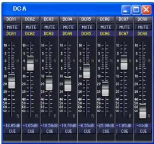
In this window you can view and edit the parameters of DCA groups 1–8.
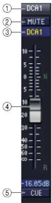
① DCA number
This is the number of the DCA group.
② MUTE
This switches DCA group muting on/off. This is linked with the DCA [MUTE] keys in the DCA strip section of the PM5D panel.
③ DCA group name
This is a text box that displays the DCA group name. You can also edit the DCA group name in this text box.
④ DCA fader
This fader adjusts the level of the DCA group. This is linked with the DCA faders in the DCA strip section of the PM5D panel.
The current fader value is shown in the numeric box immediately below the fader.
When you hold down the
If a DCA group is set to Recall Safe, the R character at the lower right of the fader is displayed in orange.
⑤ CUE
This button cue-monitors the DCA group. This is linked with the DCA [CUE] keys in the DCA channel strip of the PM5D panel.
Selected Channel window
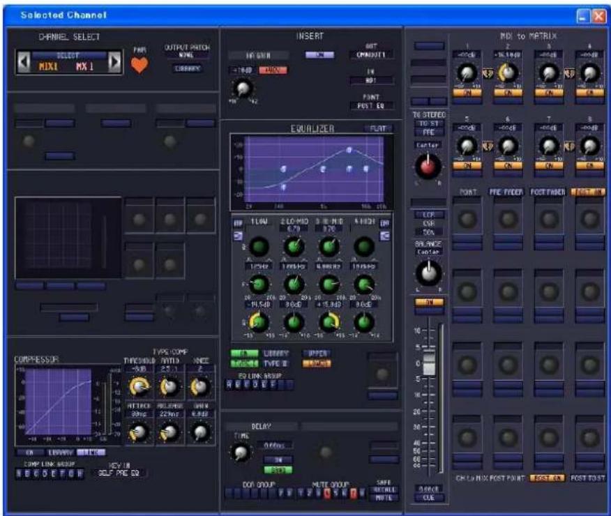
Here you can set the parameters of the currently selected input channel (input channels 1–48, ST IN channels 1–4, FX RTN channels 1–4) or output channel (MIX channels 1–24, MATRIX channels 1–8, STEREO A/B channels). The type of parameters that can be edited in this window will depend on the type of the currently selected channel. The parameters of the Selected Channel window are explained below, in the order of input channels (input channels 1–48, ST IN channels 1–4, FX RTN channels 1–4), MIX channels, MATRIX channels, and STEREO A/B channels.
If an input channel is selected
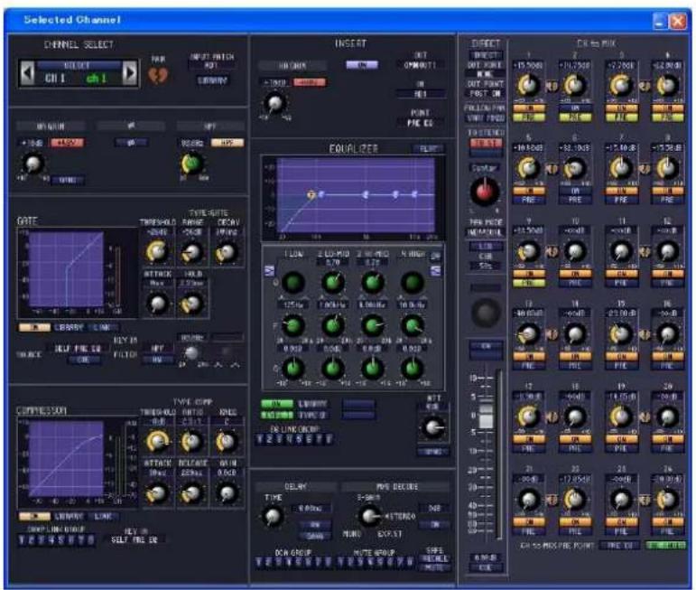
NOTE Unless otherwise specified, the parameters explained below are common to input channels 1–48, ST IN channels 1–4, and FX RTN channels 1–4.
☐ CHANNEL SELECT (Channel selection)
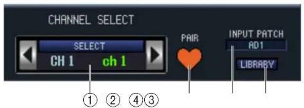
① SELECT (Channel selection)
Indicates the number and name of the channel you are editing. To switch channels, use the SELECT button or the // buttons at left and right. You can also edit the channel name in the text box.
② PAIR
Indicates the pair status of the selected channel. You can click the heart symbol to enable/disable pairing.
③ INPUT PATCH
Selects the input source assigned to the input channel (for the selectable input sources, p.8).
④ LIBRARY
Accesses the INPUT CH page of the LIBRARY window.
☐ HA GAIN/∅/HPF (HA gain/phase/high-pass filter)
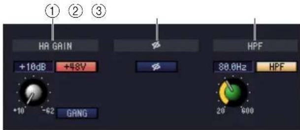
① HA GAIN
Adjusts the gain of the internal HA (PM5D-RH model and DSP5D only) or of the external HA (AD8HR, AD824) patched to the input channel. The current setting is shown in the numerical box above the knob. You can also use the +48V button to switch phantom power on/off. You can use the GANG button to link the gain of two channels that are patched adjacent to each other, so that their current offset value will be maintained.
② ∅ (Phase)
Inverts the phase of the signal after AD conversion.
③ HPF (High Pass Filter)
Use the HPF button at the right to switch the high-pass filter on/off. You can use the knob at left to adjust the cut-off frequency. The current setting is shown in the numerical box above the knob.
☐ GATE (except for FX RTN channels)
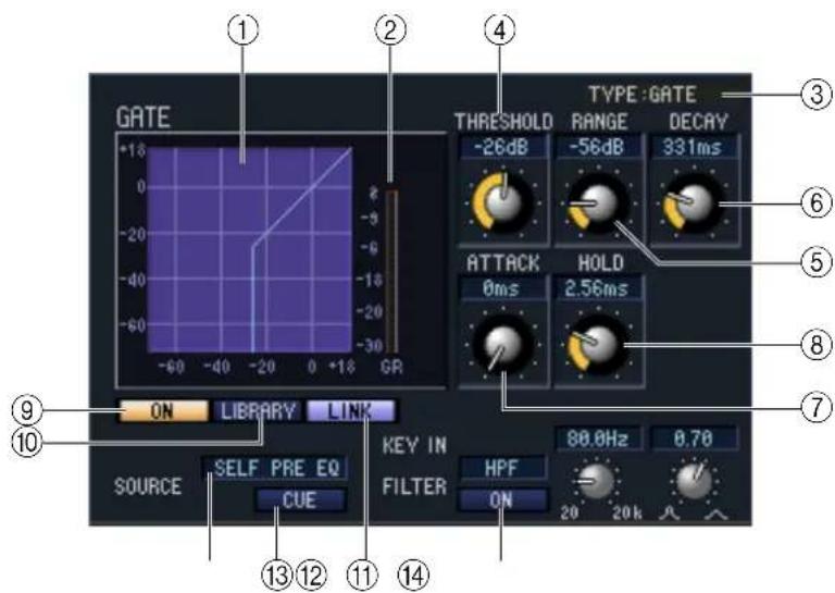
① Gate graph
Indicates the approximate response for the gate of the currently selected channel.
② GR meter
This meter indicates the amount of gain reduction.
③ TYPE
Indicates the type of the currently selected gate.
④ THRESHOLD (Threshold level)
Specifies the level at which the gate will open and close. The gate will open when the key-in signal exceeds this level, and will close when the signal falls below this level.
⑤ RANGE
Specifies the amount by which the signal is attenuated while the gate is closed.
⑥ DECAY (Decay time)
Specifies the time over which the gate will close after the hold time has elapsed.
⑦ ATTACK (Attack time)
Specifies the time from when the key-in signal exceeds the threshold level until the gate opens.
⑧ HOLD (Hold time)
Specifies the time that the gate will remain open after the key-in signal falls below the threshold.
⑨ ON (On/off)
This button switches the gate on/off.
⑩ LIBRARY
This button accesses the gate library. Clicking this button will open the GATE page of the LIBRARY window.
⑪ LINK (Stereo link)
This button links the parameter settings and key-in signals of adjacent odd-numbered/even-numbered input channels or the L/R sides of a ST IN channel, so that gating will operate in tandem for the two channels.
⑫ KEY IN SOURCE
Select the desired key-in signal from the following choices.
| SELF PRE EQ The pre-EQ signal | of the currently selected input channel |
| SELF POST EQ The post-EQ signal | al of the currently selected input channel |
| CH 1–48 POST EQ | The post-EQ signal of the corresponding input channel (however, you can only choose channels belonging to the same group, within the seven groups CH1–8, CH9–16, CH17–24, CH25–32, CH33–40, CH41–48, and ST IN 1L/1R–4L/4R). |
| ST IN 1L/1R – 4L/4R POST EQ | |
| MIX 21–24 OUT | The output signal of the corresponding MIX channel immediately before the output attenuation |
⑬ CUE
This button cue-monitors the currently selected key-in signal.
⑭ KEY IN FILTER
Select the type of filter applied to the selected key-in signal; HPF (high pass filter), BPF (band pass filter), or LPF (low pass filter). The ON/OFF button located immediately below switches the filter on/off.
If you've selected BPF, use the two knobs at right to adjust the band pass frequency and Q. If you've selected HPF or LPF, use the knob at left to adjust the cutoff frequency.
COMPRESSOR (except for FX RTN channels)
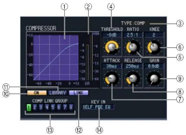
① Compressor graph
Indicates the approximate response for the compressor of the currently selected channel.
② GR meter
This meter indicates the amount of gain reduction produced by the compressor.
③ TYPE
Indicates the type of the currently selected compressor.
④ THRESHOLD (Threshold level)
Specifies the threshold level at which the compressor will operate. The input signal will start being compressed when the key-in signal exceeds this level; compression will be removed when the signal falls below this level.
⑤ RATIO
Specifies the ratio at which the input signal will be compressed when the key-in signal exceeds the threshold.
⑥ KNEE/WIDTH
If the TYPE is COMP or EXPANDER, you can set the KNEE. The KNEE is the abruptness with which the output level will change. You can choose from HARD and 1–5.
If the TYPE is COMPANDER H or COMPANDER S, you can set the WIDTH. The WIDTH is the spread between the boundary level of the compressor effect (THRESHOLD) and the boundary level of the expander effect. The expander effect will apply to levels that are lower than THRESHOLD+WIDTH.
⑦ ATTACK (Attack time)
Specifies the time from when the key-in signal exceeds the threshold level until the signal starts being compressed.
⑧ RELEASE (Release time)
Specifies the time from when the key-in signal falls below the threshold level until compression is removed.
⑨ GAIN
Adjusts the gain of the signal after it has passed through the compressor.
⑩ ON (On/off)
This button switches the compressor on/off.
⑪ LIBRARY
This button accesses the compressor library. Clicking this button will open the COMP page of the LIBRARY window.
⑫ LINK (Stereo link)
This button links the parameter settings and key-in signals of adjacent odd-numbered/even-numbered input channels or the L/R sides of a ST IN channel, so that compression will operate in tandem for the two channels.
⑬ COMP LINK GROUP (Compressor link group)
Selects the compressor link group (1–8) to which that channel belongs.
⑭ KEY IN
Selects the signal that will be used as the key-in signal. The types of signal that can be selected are the same as for the gate key-in signal ( p.24).
☐ INSERT (except for FX RTN channels)
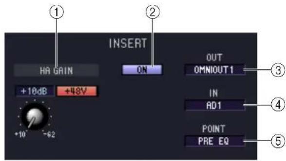
① HA GAIN (head amp gain) and +48V
Here you can adjust the HA gain for the input (if it has HA) that is patched to INSERT IN, and turn +48V on/off.
② ON (On/off)
Enables/disables insert-in/out.
③ OUT (Insert out)
Here you can select the output port that will be assigned to insert-out, from the following choices.
| NONE No assignment | |
| MIXOUT1...MIXOUT24 | The channels of MIX OUT jacks 1–24This cannot be selected on the DSP5D |
| OMNIOUT1...OMNIOUT24 | The channels of OMNI OUT jacks 1–24This cannot be selected on the DSP5D |
| S1-1, S1-2...S4-15, S4-16 Output channels of an | I/O card installed in slots 1–4 |
| FX1L, FX1R...FX8L, FX8R L/R inputs of internal | effects 1–8 |
| GEQIN1...GEQIN20 Inputs of GEQ modules 1–20 | |
| 2TR D1L, 2TR D1R...2TR D3L, 2TR D3R | L/R channels of 2TR OUT DIGITAL jacks 1–3This cannot be selected on the DSP5D |
④ IN (Insert in)
Here you can select the input port that will be assigned to insert-in, from the following choices.
| NONE No assignment | |
| AD1-AD48 INPUT jacks 1-48 | |
| AD1L, AD1R...AD4L, AD4R The L/R channels of ST IN jacks 1-4. | |
| S1-1, S1-2...S4-15, S4-16 Input channels of an I/O card installed in slots 1-4 | |
| FX1L, FX1R...FX8L, FX8R L/R outputs of internal effects 1-8 | |
| GEQOUT 1-20 Outputs of GEQ modules 1-20 | |
| 2TR D1L, 2TR D1R...2TR D3L, 2TR D3R | L/R channels of 2TR IN DIGITAL jacks 1-3This cannot be selected on the DSP5D |
| 2TR A1L, 2TR A1R, 2TR A2L, 2TR A2R | L/R channels of 2TR IN ANALOG jacks 1/2This cannot be selected on the DSP5D |
⑤ POINT (Insert point)
Selects the position at which insert-in/out will be patched. Choose from Pre EQ, Post EQ, Pre Delay, or Post Fader.
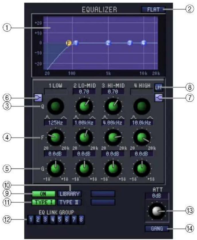
① EQ graph
Indicates the approximate response for the EQ of the currently selected channel.
② FLAT
If you click this button, the gain of all bands will be reset to 0.0 dB.
③ Q
④ F (Frequency)
⑤ GAIN
These knobs adjust the Q, center frequency, and boost/cut amount for the four bands LOW, LO-MID, HI-MID, and HIGH.
⑥ LOW shelving)
If this button is on, the LOW EQ will be switched to a shelving type (the Q knob of the LOW EQ will disappear).
⑦ HIGH shelving)
If this button is on, the HIGH EQ will be switched to a shelving type (the Q knob of the HIGH EQ will disappear).
⑧ LPF (Low Pass Filter)
If this button is on, the HIGH EQ will function as a low pass filter. The Q knob of the HIGH EQ will disappear, and the GAIN knob will act as the low pass filter on/off switch.
⑨ ON (On/off)
Switches the EQ on/off.
⑩ LIBRARY
Accesses the INPUT EQ page of the LIBRARY window.
Selects either TYPE I (an algorithm equivalent to the EQ in the earlier 02R series) or TYPE II (a newly developed algorithm) as the EQ type.
⑫ EQ LINK GROUP
Selects the EQ link group (1–8) to which that channel belongs.
⑬ ATT (Attenuation)
Adjusts the amount of attenuation/gain following AD conversion.
⑭ GANG
If this button is on, the attenuation/gain settings of two adjacent odd-numbered/even-numbered channels will be linked while maintaining the current offset value.
☐ DELAY (except for FX RTN channels)
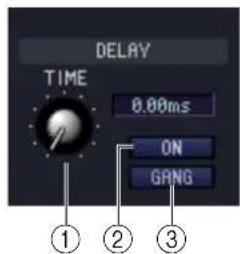
① TIME (Delay time)
Adjusts the delay time for each channel.
② ON (On/off)
Switches the delay on/off. The current value (ms units) is shown in the box at the right.
③ GANG
If this button is on, the delay time of two adjacent odd-numbered/even-numbered channels will be linked while maintaining the current offset value.
☐ M/S DECODE (except for FX RTN channels)
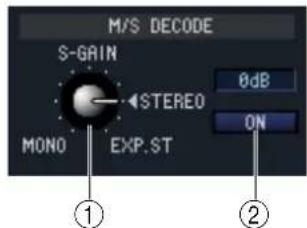
① S-GAIN
This knob sets the proportionate level of the S mic relative to the level of the M mic. The current value (dB units) is shown in the box at the right.
② ON (On/off)
This button switches M/S decoding on/off for two adjacent odd-numbered/even-numbered input channels (or ST IN channel L/R).
DCA GROUP / MUTE GROUP / SAFE
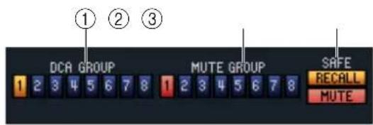
① DCA GROUP
Selects the DCA group (1–8) to which that channel belongs.
② MUTE GROUP
Selects the mute group (1–8) to which that channel belongs.
③ RECALL SAFE / MUTE SAFE
These enable/disable Recall Safe and Mute Safe for the channel.
Pan / Fader

① DIRECT (except for FX RTN channels)
Turns the direct output on/off.
② Direct Output Port (except for FX RTN channels)
Choose the port from which this input channel 1–48 or this ST IN channel 1–4 will be directly output.
| NONE No assignment | |
| S1-1, S1-2...S4-15, S4-16 Output channels of an I/O card installed in slots 1–4 | |
| 2TR D1L, 2TR D1R...2TR D3R | L/R channels of 2TR OUT DIGITAL jacks 1–3This cannot be selected on the DSP5D |
③ Direct output point (except for FX RTN channels)
Here you can select the direct out point from the following choices: PRE ATT, PRE HPF, PRE EQ, PRE FADER, and POST ON.
④ FOLLOW PAN
Use the following two buttons to specify how the signal sent from the input channel to the MIX bus will be affected by the TO ST PAN knob (⑥).
• V ARI button
If this button is on, the PAN knob displayed in the CH to MIX area will be linked with the TO ST PAN knob if VARI-type MIX buses are paired.
- FIXED button
If this button is on, the signal from after the TO ST PAN (⑥) knob will be sent to FIXED-type MIX buses.
⑤ TO ST (To stereo)
This is an on/off switch for the signal sent from the input channel to the STEREO bus. This is linked with the [TO STEREO] key in the SELECTED CHANNEL section of the panel.
⑥ TO ST PAN (To stereo pan)
Adjusts the panning of the signal sent from the input channel to the STEREO bus. This is linked with the encoder of each channel if PAN is selected as the encoder mode, and with the [PAN] encoder of the SELECTED CHANNEL section. This may be BALANCE depending on the PAN mode.
⑦ PAN MODE SELECT
Here you can select the PAN mode from the following choices: INDIVIDUAL, GANG PAN, INV. GANG, and BALANCE.
⑧ LCR
Turns LCR mode on/off for each channel. If this is turned on for a channel, you can use the TO ST PAN (⑥) knob to simultaneously control the level of the signal sent to the STEREO bus L/R channels and CENTER channel.
⑨ CSR (Center Side Ratio)
This adjusts the level ratio (0–100%) of the CENTER channel relative to the STEREO bus L/R channels. To change the value, drag upward or downward inside the numerical box.
⑩ ON
Switches the input channel on/off. This is linked with the INPUT channel strip CH [ON] keys on the PM5D panel.
⑪ Fader
Adjusts the input level of the input channel. This is linked with the INPUT channel strip faders on the PM5D panel. The current value is shown in the numerical box immediately below. A level meter is shown beside the fader.
⑫ CUE
This button cue-monitors the signal of the input channel. This is linked with the INPUT channel strip [CUE] keys on the PM5D panel. If SOLO is active, this will function as SOLO.
☐ CH to MIX (Channel to mix)
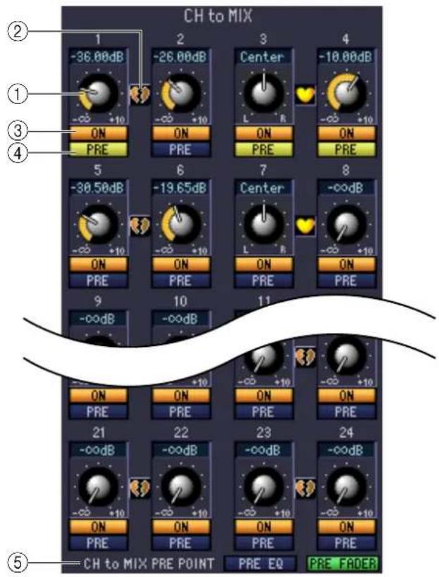
① MIX send level
This adjusts the send level of the signal sent from the input channel to VARI-type MIX buses. The current value is shown in the numerical box immediately above.
② Pair
This indicates the pairing status of adjacent odd-numbered/even-numbered MIX channels. You can click the heart symbol to enable/disable pairing.
③ ON (MIX send on/off)
This is an on/off switch for the signal sent from the input channel to the MIX bus.
④ PRE (Pre/Post)
This selects PRE or POST as the point from which the signal is sent from the input channel to the MIX bus.
⑤ CH to MIX PRE POINT
This selects PRE EQ or PRE FADER as the point from which the signal is sent when the PRE button (④) is set to PRE.
NOTE If the PRE button is set to POST, you can select either POST ON or POST TO ST as the signal send location individually for each MIX bus (→ p.35).
☐ CHANNEL SELECT (Channel selection)
Except for the fact that the operations apply to a MIX channel, and that INPUT PATCH is replaced by OUTPUT PATCH, this is the same as for the channel select area of input channels ( p.22).
COMPRESSOR
Except for the fact that the COMP LINK GROUP is A–H, and that the types of signal that can be selected for key-in are different, this is the same as for the compressor of an input channel ( p.25).
INSERT
Except for the fact that the insert points that can be selected are different, this is the same as for the insert settings of an input channel ( p.26).
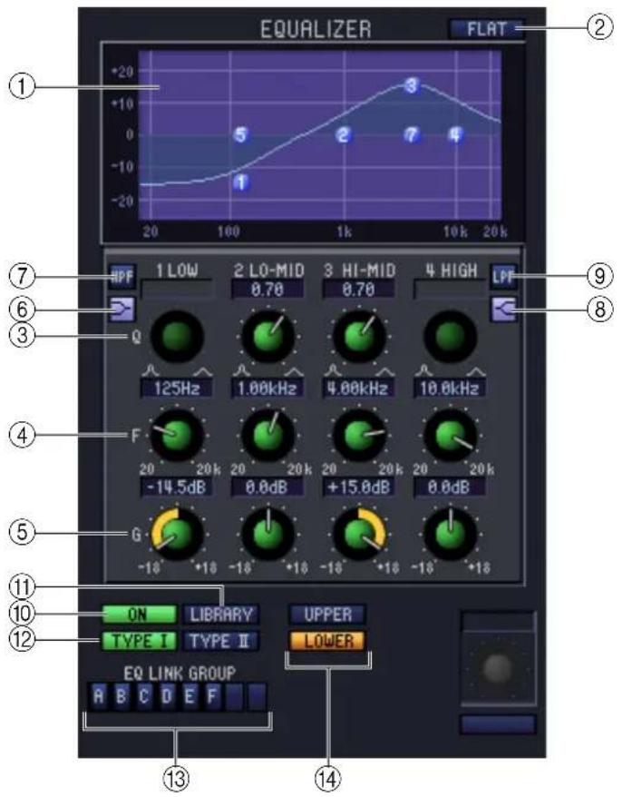
① EQ graph
Indicates the approximate response for the EQ of the currently selected channel.
② FLAT
If you click this button, the gain of all bands will be reset to 0.0 dB.
③ Q
④ F (Frequency)
⑤ GAIN
These knobs adjust the Q, center frequency, and boost/cut amount for each band.
⑥ LOW shelving)
If this button is on, the LOW EQ will be switched to a shelving type (the Q knob of the LOW EQ will disappear).
⑦ HPF (High Pass Filter)
If this button is on, the LOW EQ will function as a high pass filter EQ. The Q knob of the LOW EQ will disappear, and the GAIN knob will act as the high pass filter on/off switch.
⑧ HIGH shelving)
If this button is on, the HIGH EQ will be switched to a shelving type (the Q knob of the HIGH EQ will disappear).
⑨ LPF (Low Pass Filter)
If this button is on, the HIGH EQ will function as a low pass filter. The Q knob of the HIGH EQ will disappear, and the GAIN knob will act as the low pass filter on/off switch.
⑩ ON (On/off)
Switches the EQ on/off.
⑪ LIBRARY
Accesses the OUTPUT EQ page of the LIBRARY window.
Selects either TYPE I (an algorithm equivalent to the EQ in the earlier 02R series) or TYPE II (a newly developed algorithm) as the EQ type.
⑬ EQ LINK GROUP
Selects the EQ link group (A–F) to which that channel belongs.
⑭ UPPER/LOWER
Switches the four bands affected by controls ③–⑨ between LOWER (1 LOW–4 HIGH) and UPPER (5 LOW–8 HIGH).
DELAY
This is the same as for the delay settings of an input channel ( p.28).
☐ DCA GROUP / MUTE GROUP / SAFE
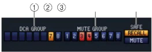
① DCA GROUP
Selects the DCA group (7/8) to which the MIX channel belongs.
② MUTE GROUP
Selects the mute group (1–8) to which the MIX channel belongs.
③ RECALL SAFE / MUTE SAFE
These enable/disable Recall Safe and Mute Safe for the MIX channel.
Pan / Fader

① TO ST (To stereo)
This is an on/off switch for the signal sent from the MIX channel to the STEREO bus. The PRE button located below selects PRE (immediately before the MIX [ON] key) or POST (immediately after the MIX [ON] key) as the point from which the signal is sent from the MIX channel to the STEREO bus.
② TO ST PAN (To stereo pan)
Sets the panning of the signal sent from the MIX channel to the STEREO bus.
③ LCR
Turns LCR mode on/off for each channel. If this is turned on for a channel, you can use the TO ST PAN (②) knob to simultaneously control the level of the signal sent to the STEREO bus L/R channels and CENTER channel.
④ CSR (Center Side Ratio)
This adjusts the level ratio (0–100%) of the CENTER channel relative to the STEREO bus L/R channels. To change the value, drag upward or downward inside the numerical box.
⑤ BALANCE
This adjusts the left/right output balance of paired channels. This is not shown if pairing is not specified.
⑥ ON
Switches the MIX channel on/off. This is linked with the MIX [ON] keys in the MIX section of the PM5D panel.
⑦ Fader
Adjusts the output level of the MIX channel. This is linked with the MIX encoders on the PM5D panel (if the [MIX MASTER] key is on). The current value is shown in the numerical box immediately below. A level meter is shown beside the fader.
⑧ CUE
This button cue-monitors the signal of the MIX channel. This is linked with the MIX [CUE] keys in the MIX section of the PM5D panel. If SOLO is active, this will function as SOLO.
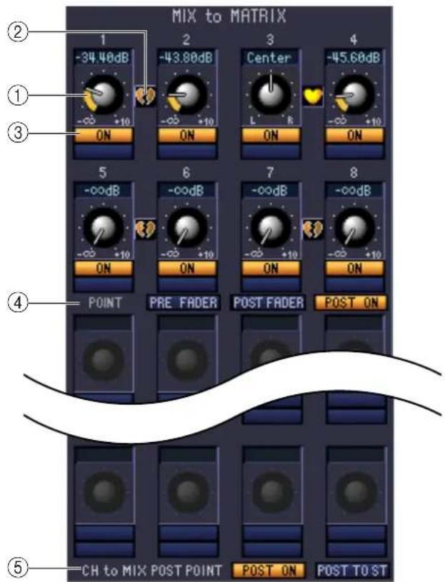
① MATRIX send level
This adjusts the send level of the signal sent from the MIX channel to the MATRIX buses.
② Pair
This indicates the pairing status of adjacent odd-numbered/even-numbered MATRIX channels. You can click the heart symbol to enable/disable pairing.
③ ON (MATRIX send on/off)
This is an on/off switch for the signal sent from the MIX channel to the MATRIX bus.
④ POINT (Send point)
Selects the point from which the signal is sent from the MIX channel to the MATRIX bus. You can choose PRE FADER (immediately before the fader), POST FADER (immediately after the fader), or POST ON (immediately after the MIX [ON] key).
⑤ CH to MIX POST POINT
Here you can select either POST ON or POST TO ST as the Post position that will be sent from all input channels to the currently selected MIX bus.
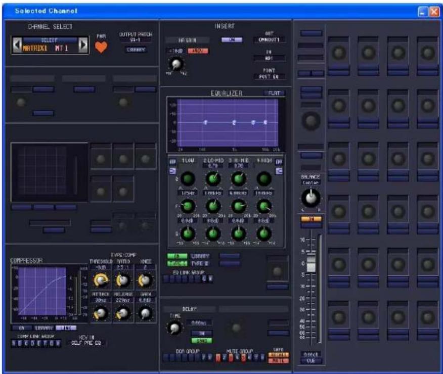
☐ CHANNEL SELECT (Channel selection)
Except for the fact that the operations apply to a MATRIX channel, and that INPUT PATCH is replaced by OUTPUT PATCH, this is the same as for the channel select area of input channels ( p.22).
COMPRESSOR
Except for the fact that the COMP LINK GROUP is A–H, and that the types of signal that can be selected for key-in are different, this is the same as for the compressor of an input channel ( p.25).
INSERT
Except for the fact that the insert points that can be selected are different, this is the same as for the insert settings of an input channel ( p.26).
EQUALIZER
Except for the fact that there is no LOWER/UPPER button, and that the EQ LINK groups are G/H, this is the same as for the equalizer of a MIX channel ( p.32).
DELAY
This is the same as for the delay settings of an input channel (p.28).
DCA GROUP / MUTE GROUP / SAFE
These are the same as the DCA Group / Mute Group / Safe settings of a MIX channel (→ p.33).
Pan / Fader
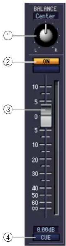
① BALANCE
This adjusts the left/right output balance of paired channels. This is not shown if pairing is not specified.
② ON
This switches the MATRIX channel on/off. This is linked with the MATRIX [ON] keys in the MATRIX section of the PM5D panel.
③ Fader
This adjusts the output level of the MATRIX channel. This is linked with the MATRIX encoders in the MATRIX section of the PM5D panel. The current value is shown in the numerical box immediately below. A level meter is shown beside the fader.
④ CUE
This button cue-monitors the signal of the MATRIX channel. This is linked with the MATRIX [CUE] keys in the MATRIX section of the PM5D panel. If SOLO is active, this will function as SOLO.
If a STEREO A/B channel is selected
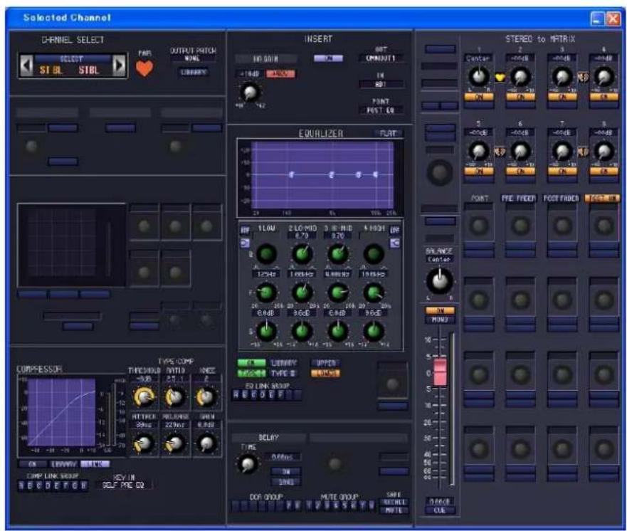
☐ CHANNEL SELECT (Channel selection)
Except for the fact that your editing applies to a STEREO A/B channel, this is the same as the channel selection for an input channel ( p.22).
COMPRESSOR
Except for the fact that the COMP LINK GROUP is A–H, and that the types of signal that can be selected for key-in are different, this is the same as for the compressor of an input channel ( p.25).
INSERT
Except for the fact that the insert points that can be selected are different, this is the same as for the insert settings of an input channel ( p.26).
EQUALIZER
This is the same as the equalizer settings of a MIX channel ( p.32).
□ DELAY
This is the same as for the delay settings of an input channel (→ p.28).
DCA GROUP / MUTE GROUP / SAFE
These are the same as the DCA Group / Mute Group / Safe settings of a MIX channel (→ p.33).
Pan / Fader
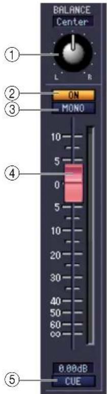
① BALANCE
Adjusts the left/right output balance of the STEREO A/B channel.
② ON
This switches the STEREO A/B channel on/off. This is linked with the STEREO [ON] key in the STEREO A/B channel strip of the PM5D panel.
③ MONO (ST B channel only)
Switches the ST B channel between stereo/mono.
④ Fader
Adjusts the output level of the STEREO A/B channel. This is linked with the STEREO fader in the STEREO A/B channel strip of the PM5D panel. The current value is shown in the numerical box immediately below. A level meter is shown beside the fader.
⑤ CUE
This button cue-monitors the signal of the STEREO A/B channel. This is linked with the STEREO [CUE] key in the STEREO A/B channel strip of the PM5D panel. If SOLO is active, this will function as SOLO.
STEREO to MATRIX
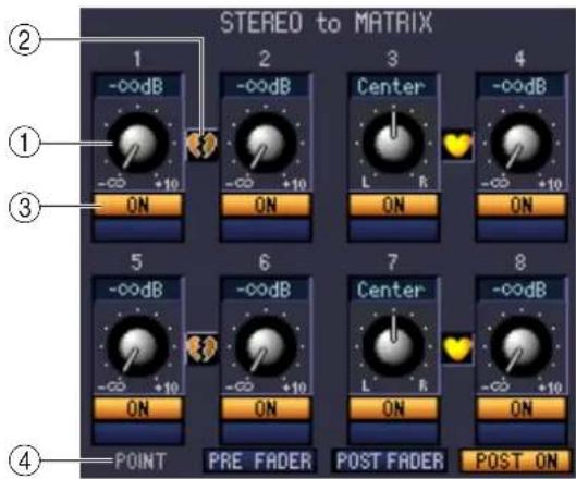
① MATRIX send level
Here you can adjust the send levels of the signals sent from the STEREO A/B channels to the MATRIX bus.
② Pair
This indicates the pairing status of adjacent odd-numbered/even-numbered MATRIX channels. You can click the heart symbol to enable/disable pairing.
③ ON (MATRIX send on/off)
This is an on/off switch for the signal sent from the STEREO A/B channel to the MATRIX bus.
④ POINT (Send point)
Selects the point from which the signal is sent from the STEREO A/B channel to the MATRIX bus. You can choose PRE FADER (immediately before the fader), POST FADER (immediately after the fader), or POST ON (immediately after the STEREO [ON] key).
Patch Editor window
Here you can assign the input/output port for each channel, its direct output, and its insert-in/out.
This window is divided into INPUT PATCH, OUTPUT PATCH, INPUT INSERT PATCH, OUTPUT INSERT PATCH, DIRECT OUT PATCH, and PATCH LIST pages. To switch pages, click the tabs shown in the upper part of the window.
INPUT PATCH page
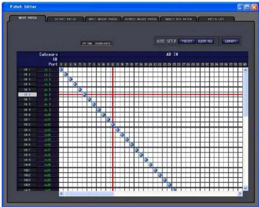
Here you can select the input port that is assigned to the input of each input channel. Except for the fact that you can resize the window, the basic operation is the same as in the PM5D's INPUT PATCH screen.
NOTE
• VIRTUAL SOUNDCHECK is a display-only function.
- In DSP5D Editor, VIRTUAL SOUNDCHECK will be lit only if you operate the PM5D with the PM5D and DSP5D connected.
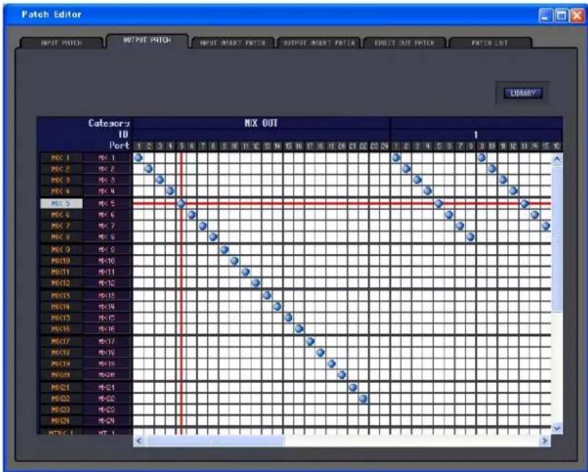
Here you can select the output port that is assigned to the input of each output channel. Except for the fact that you can resize the window, the basic operation is the same as in the PM5D's OUTPUT PATCH screen.
INPUT INSERT PATCH page
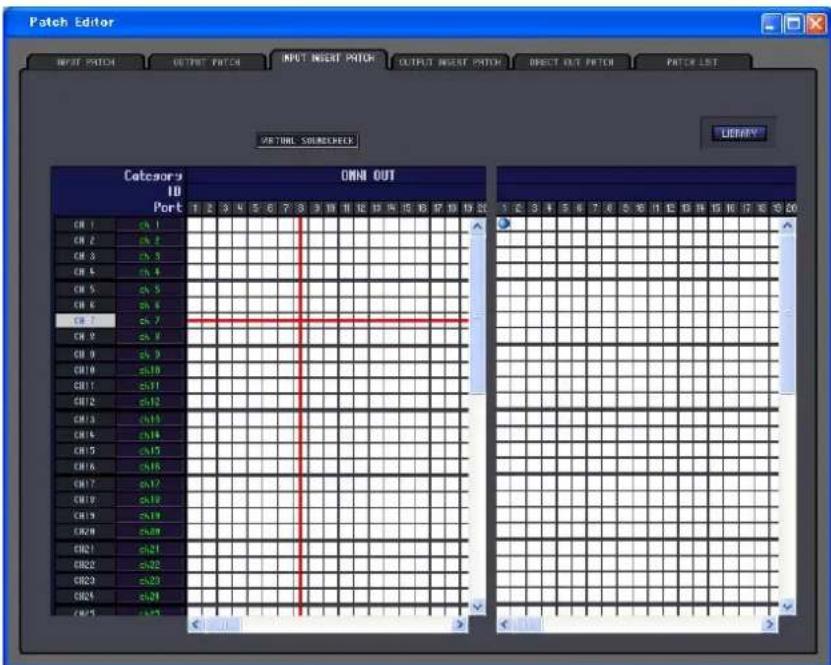
Here you can assign input/output ports to the insert-in/out of each input channel. Select the output port in the left side of the screen, and the input port in the right side of the screen. Except for the fact that you can resize the window, the basic operation is the same as in the PM5D's INPUT INSERT PATCH screen.
NOTE
• VIRTUAL SOUNDCHECK is a display-only function.
- In DSP5D Editor, VIRTUAL SOUNDCHECK will be lit only if you operate the PM5D with the PM5D and DSP5D connected.
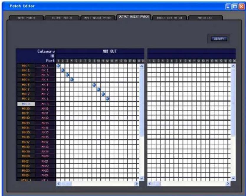
Here you can assign input/output ports to the insert-in/out of each output channel. Select the output port in the left side of the screen, and the input port in the right side of the screen. Except for the fact that you can resize the window, the basic operation is the same as in the PM5D's OUTPUT INSERT PATCH screen.
DIRECT OUTPUT PATCH page
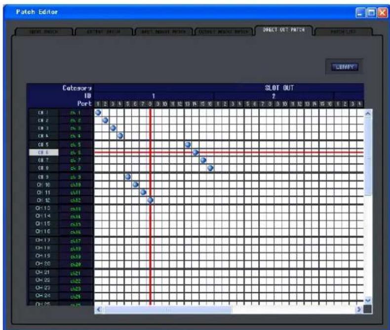
Here you can select the output port that will directly output each input channel. Except for the fact that you can resize the window, the basic operation is the same as in the PM5D's DIRECT OUTPUT PATCH screen.
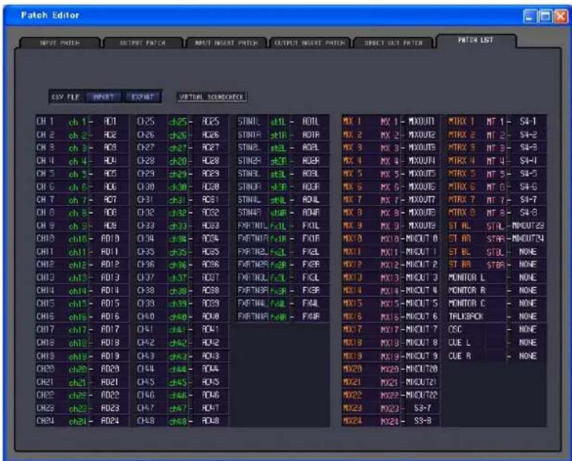
Here you can view and edit the input patch and output patch settings. Input patch, output patch, and channel name data that was written to a CSV file by the PM5D itself can also be loaded into this page. Conversely, the settings in this page can be written to a CSV file that can be loaded into the PM5D.
NOTE
• VIRTUAL SOUNDCHECK is a display-only function.
- In DSP5D Editor, VIRTUAL SOUNDCHECK will be lit only if you operate the PM5D with the PM5D and DSP5D connected.
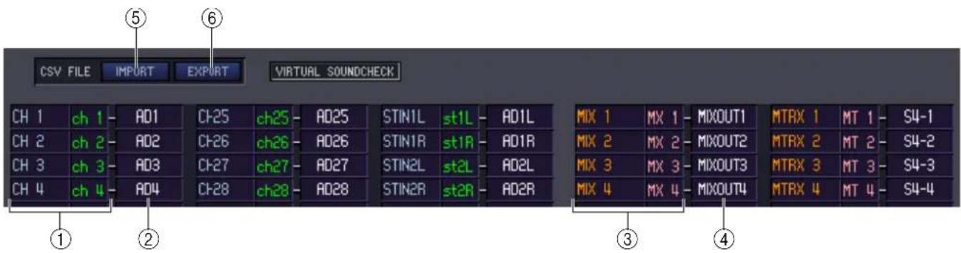
① Input channel number Input channel name
This is the number and name of the input channel. You can click the channel name box to edit the name in this page.
② Input port
This shows the input port assigned to the input channel. You can click this box and choose the input port from the popup menu that appears.
③ Output channel number Output channel name
This is the number and name of the output channel. You can click the channel name box to edit the name in this page.
④ Output port
This shows the output port assigned to the output channel. You can click this box and choose the output port from the popup menu that appears.
⑤ IMPORT (Import a CSV file)
Input patch, output patch, and channel name data from CSV files written by the PM5D can be loaded into the PATCH LIST page by clicking this button.
When you click this button, a dialog box will appear as shown at right, allowing you to specify the folder containing the CSV files you want to load.
Specify the folder that contains CSV files, and click the OK button. If the specified folder contains CSV files, that data will be loaded into the PATCH LIST page.
NOTE
If the specified folder does not contain the necessary CSV file, the settings in the PATCH LIST page will not change. For example if the folder contains only an input patch CSV file, only the input patch settings of the PATCH LIST page will be loaded, and the remaining settings will not change.
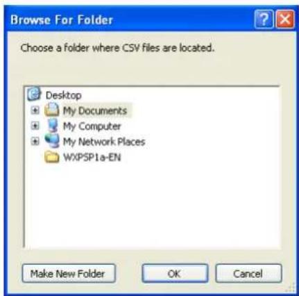
⑥ EXPORT (Export a CSV file)
By clicking this button, input patch, output patch, and channel name data can be written to a CSV file that can be loaded by the PM5D.
When you click this button a dialog box will appear, allowing you to specify a folder for the exported CSV files. Specify the folder in which the CSV files will be saved, and click the OK button. Separate CSV files containing the input patch, output patch, and channel name data will be saved in the folder you specified. You can use a memory card to load these CSV files into the PM5D.
Surround Editor window
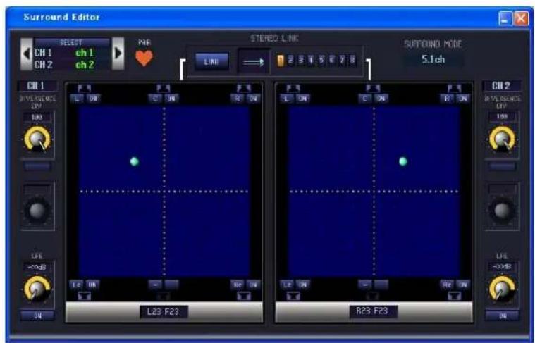
Here you can make surround panning settings for the two currently selected input channels.

① SELECT (Channel selection)
This area displays the name and number of the two channels selected for operations (two adjacent odd-numbered/even-numbered input channels, a ST IN channel, or an FX RTN channel). To switch channels, use the SELECT button or the 📁 buttons at left and right. You can also edit the channel name in the text box.
② PAIR
Indicates the pair status of the two selected channels. If an input channel is selected, you can click the heart symbol to enable/disable pairing.
③ LINK
Specifies whether movement of the sound image will be linked for the two selected channels. If this button is on, the sound image of the two channels will be linked according to the link pattern you select using LINK PATTERN SELECT buttons 1–8.
④ LINK PATTERN SELECT
These buttons select link patterns 1–8. The currently selected pattern is shown graphically at the left.
⑤ SURROUND MODE
This indicates the currently selected surround mode. You can click this area to switch the mode.
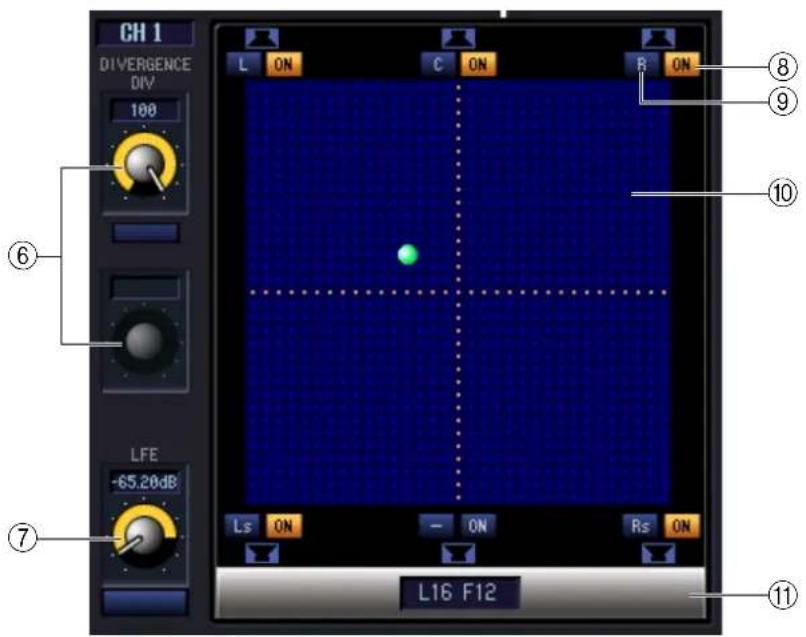
⑥ DIVERGENCE
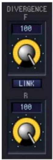
These controls specify the proportion at which the signals are sent to each surround bus when the input channel is positioned in the center. The operable parameters will change as follows, according to the surround mode that is currently selected.
- Surround mode= 3-1ch/5.1ch
The Div knob will be operable, allowing you to adjust the front divergence. Use this knob to specify the proportion (0–100) at which a signal positioned in the center will be sent to the center bus (C) and the left/right buses (L, R).
• Surround mode= 6.1ch
The F knob and R knob will be operable, allowing you to adjust the front and rear divergence separately. Use these two knobs to specify the proportion (0–100) at which a signal positioned in the center will be sent to the center buses (C, Bs) and the left/right buses (L, R, Ls, Rs). In addition, a LINK button that links front and rear divergence is displayed between the F knob and R knob. If you turn the LINK button on, the value of the F knob will be copied to the R knob, and the two knobs will be linked.
⑦ LFE (Low Frequency Effect)
Use the LFE knob to adjust the level of the signal sent from the input channel to the subwoofer LFE bus, over a range of - to 0 dB. The ON/OFF button is an on/off switch for sending to the MIX bus assigned to the LFE channel.
⑧ SURROUND BUS ON (Surround bus on/off)
These buttons are on/off switches for the signal sent from the currently selected input channel to the corresponding surround bus. You can click the surround bus name buttons at left to move the panning to the position of the corresponding surround bus.
⑨ PANNING buttons
These buttons correspond to each surround bus. Speaker icons are displayed to indicate the surround buses that are available for the current surround mode.
⑩ Grid
This specifies the surround panning for the currently selected input channel, relative to the mid-point of the speaker locations. The current setting is indicated by a ● symbol. You can drag this symbol up, down, left, or right to move the panning.
⑪ PAN POSITION
The surround panning of the currently selected input channel is shown here as front/rear left/right coordinate values.
GEQ window
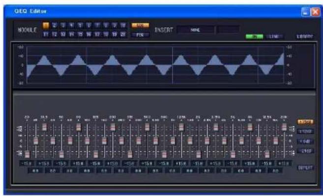
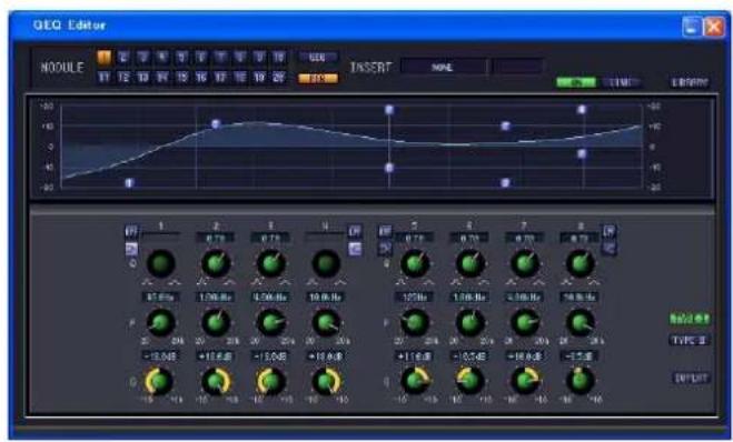
In this window you can select the insertion destination of GEQ modules 1–20, and edit the parameters. The number of GEQ modules will depend on the “Number of Effects” setting specified in the Mixer Setup window.

① MODULE (Module selection)
Selects the GEQ module that you want to edit or view.
② GEQ/PEQ (GEQ/PEQ select button)
This switches the module between GEQ operation or PEQ operation.
GEQ lets you use 31 bands to specify the module's response, and PEQ lets you use eight bands.
③ INSERT (Insert destination)
Select one of the following as the insert destination for the currently selected GEQ module.
| NONE Not inserted | |
| INS CH1...INS CH48 Input channel 1–48 insert | in/out |
| INS STIN1L, INS STIN1R...INS STIN4R ST IN | channel 1–4 (L/R) insert in/out |
| INS MIX1...INS MIX24 MIX channel 1–24 insert | in/out |
| INS MTRX1...INS MTRX8 MATRIX channel 1–8 | insert in/out |
| INS STAL, INS STAR STEREO A channel (L/R) insert in/out | |
| INS STBL, INS STBR STEREO B channel (L/R) insert in/out | |
| INS MON L, INS MON R, INS MON C MONITOR channel (L/R/C) insert in/out | |
④ ON (GEQ on/off)
Switches the currently selected GEQ module on/off.
⑤ LINK
This button links the settings of the adjacent odd-numbered/even-numbered GEQ modules. When you click this button, a window will appear, asking you to confirm the operation. Click the appropriate button to choose the source/destination module for the parameters that will be copied. If you click the RESET BOTH button, the parameters of both modules will be reset to their default value.
⑥ LIBRARY
This button access the GEQ LIBRARY window in GEQ mode, or the OUTPUT EQ LIBRARY window in PEQ mode.
bar_line
| Time | Value | |------|-------| | 20 | -6.5 | | 25 | +3.0 | | 31.5 | +4.0 | | 40 | +1.5 | | 50 | -2.0 | | 63 | -3.0 | | 80 | +4.0 | | 100 | +2.5 | | 125 | +10.5 | | 160 | +7.5 | | 200 | +2.0 | | 250 | +3.5 | | 315 | -3.5 | | 400 | +4.5 | | 500 | +6.5 | | 630 | +5.5 | | 900 | +3.0 | | 1h | -2.5 | | 1.25k | -6.5 | | 1.6k | -15.0 | | 2k | +15dB | | 2.5k | +12dB | | 3.15k| +6dB | | 4h | -24dB | EQFLAT⑦ GEQ graph
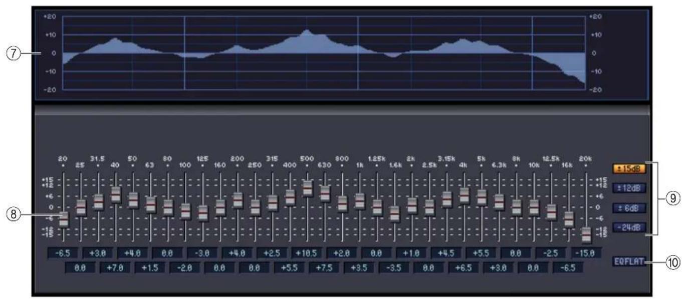
This graph shows the response of the currently selected GEQ module.
⑧ GEQ faders
These faders cut/boost the frequency bands of the GEQ module. The value of each fader is shown in the numerical box below it.
⑨ LIMIT
The range and direction of adjustment controlled by the faders can be selected from the following: ±15 dB, ±12 dB, ±6 dB (these are valid in both the boost and cut directions), or -24 dB (valid only in the cut direction).
⑩ EQ FLAT
This button resets all GEQ faders to the 0 dB position.
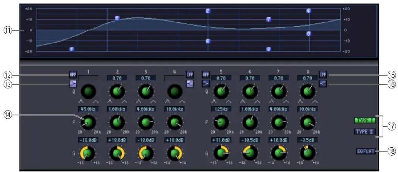
⑪ PEQ graph
This graph shows the response of the currently selected module.
⑫ HPF (High Pass Filter) button
If this button is on, band 1 or 5 will change to a high-pass filter. The Q knob for 1 or 5 will disappear, and the GAIN knob will operate as a switch that turns the high-pass filter on/off.
⑬ Low Shelving button
If this button is on, band 1 or 5 will change to a shelving-type filter. (The Q knob for 1 or 5 will disappear.)
⑭ PEQ knobs
The three knobs Q, F (center frequency), and G (gain) specify the response for each of the eight bands. You can edit the value by using the mouse to operate the knobs, or by double-clicking the value and typing the desired value.
⑮ LPF (Low Pass Filter) button
If this button is on, band 4 or 8 will change to a low-pass filter. The Q knob for 4 or 8 will disappear, and the GAIN knob will operate as a switch that turns the low-pass filter on/off.
⑯ High Shelving button
If this button is on, band 4 or 8 will change to a shelving-type filter. (The Q knob for 4 or 8 will disappear.)
⑰ TYPE I / TYPE II (EQ type)
Here you can select either TYPE I (the same algorithm as on the previous 02R series) or TYPE II (a newly developed algorithm) as the EQ type.
⑱ EQ FLAT button
This button resets all gain controls to the 0 dB position.
Effect Editor window
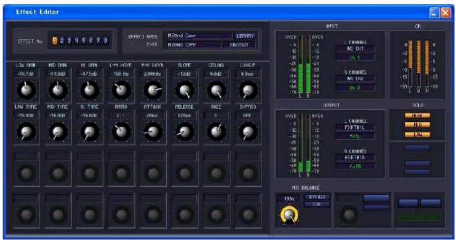
Here you can select the effect type for internal effects 1–8, edit the parameters, and specify the input/output patching. The number of available effects can be specified in the Mixer Setup window.
NOTE You can also open multiple Effect Editor windows to simultaneously view the settings of different-numbered internal effects. However, the parameters of the unit itself will change in tandem with parameter operations in the window only in Effect Editor windows that are not [Locked].
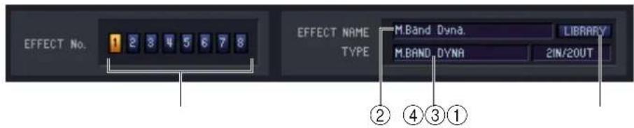
① EFFECT No. (Effect number)
Selects the number (1–8) of the internal effect you want to edit.
HINT Alternatively, you can use the Menu bar to choose [Windows] menu → [Effect Editor], and select an internal effect 1–8 from the sub-menu.
② EFFECT NAME
Indicates the title of the effect selected for internal effect 1–8.
③ EFFECT TYPE
Indicates the currently selected effect type. You can also switch the effect type from this window. To do so, click the text box, and select the desired effect type from the popup menu that appears.
④ LIBRARY
This button accesses the effect library. Clicking this button will open the EFFECT page of the LIBRARY window.
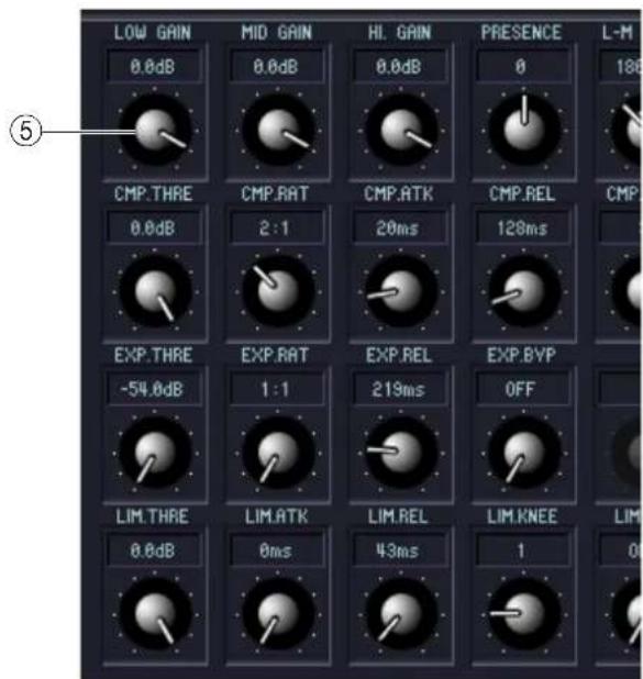
⑤Effect parameters
This area shows the effect parameters and knobs for the currently selected effect type.
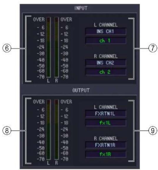
⑥ Input meter
Indicates the level of the signal being input to the internal effect.
⑦ Input patch
Click the L CHANNEL or R CHANNEL area, and choose one of the following as the signal route that will be patched to the L/R input channels of the internal effect.
| NONE Not inserted | |
| MIX 1...MIX 24 Output of MIX channels 1–24 | |
| INS CH1...INS CH48 Insert Out of input channels 1–48 | |
| INS STIN1L, INS STIN1R...INS STIN4L, INS STIN4R Insert Out of ST IN channels 1–4 (L/R) | |
| INS MIX1...INS MIX24 Insert Out of MIX channels 1–24 | |
| INS MTRX1...INS MTRX8 Insert Out of MATRIX channels 1–8 | |
| INS STAL, INS STAR STEREO A channel (L/R) insert out | |
| INS STBL, INS STBR STEREO B channel (L/R) insert out | |
| INS MON L, INS MON R, INS MON C MONITOR channel (L/R/C) insert out |
If you select something other than NONE or INS MON as the insert destination, the channel name will appear in the box located immediately below.
⑧ Output meter
Indicates the level of the signal being output from the internal effect.
⑨ Output patch
Click the L CHANNEL or R CHANNEL area, and choose one of the following as the signal route that will be patched to the L/R output channels of the internal effect.
| NONE Not inserted | |
| CH 1...CH 48 Input channel 1–48 input | |
| STIN1L, STIN1R...STIN4L, STIN4R ST IN channel 1–4 (L/R) input | |
| FXRTN1L, FXRTN1R...FXRTN4L, FXRTN4R FX RTN channel 1–4 (L/R) input | |
| INS CH1...INS CH48 Input channel 1–48 insert in | |
| INS STIN1L, INS STIN1R...INS STIN4L, INS STIN4R ST IN channel 1–4 (L/R) insert in | |
| INS MIX1...INS MIX24 MIX channel 1–24 insert in | |
| INS MTRX1...INS MTRX8 MATRIX channel 1–8 insert in | |
| INS STAL, INS STAR | STEREO A channel (L/R) insert in |
| INS STBL, INS STBR | STEREO B channel (L/R) insert in |
| INS MON L, INS MON R, INS MON C | MONITOR channel (L/R/C) insert in |
If you select something other than NONE or INS MON as the insert destination, the channel name will appear in the box located immediately below.
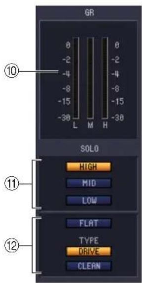
⑩ GR meter
If “044 M.BAND DYNA”, “045 M.BAND COMP” or “055 De-Esser” are selected as the effect type, this indicates the gain reduction amount for the H (HIGH), M (MID), and L (LOW) bands.
⑪ SOLO
If “044 M.BAND DYNA” or “045 M.BAND COMP” are selected as the effect type, these buttons allow you to monitor only the specified band from the three bands HIGH, MID, and LOW.
⑫ Equalizer
If "053 EQUALIZER601" is selected as the effect type, the FLAT button which sets the EQ values to a flat state and the DRIVE button and CLEAN button which specify the EQ type will become active.
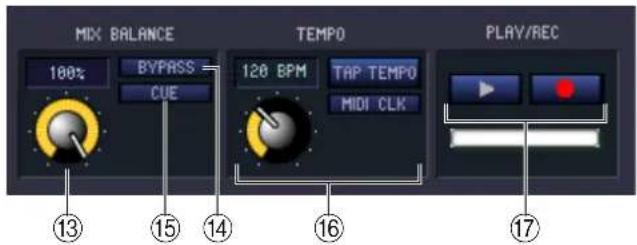
⑬ MIX BALANCE
Adjusts the balance of the effect sound relative to the original sound. 0 (%) outputs only the original sound, and 100 (%) outputs only the effect sound.
⑭ BYPASS
This button temporarily bypasses the effect.
⑮ CUE
This button cue-monitors the output of the currently selected effect.
⑯ TEMPO
If a tempo-type or modulation-type effect is selected, this allows you to adjust time-related parameters such as DELAY (delay time) and FREQ. (modulation speed).
To set the value of the TEMPO parameter, you can either input the BPM (Beats Per Minute) in the numerical box, or repeatedly click the TAP TEMPO button at the desired tempo.
If the MIDI CLK button is on, the TEMPO parameter value will synchronize to the MIDI timing clock being received from the MIDI port.
⑰ PLAY/REC (Play/Record) buttons
If "042 FREEZE" is selected as the effect type, you can use these buttons to record and play back the signal being input to the effect.
DCA/Mute Group window
In this window you can select the channels that will be assigned to each DCA group and mute group. This window is divided into two pages; the DCA GROUP ASSIGN page and the MUTE GROUP ASSIGN page.
DCA GROUP ASSIGN page
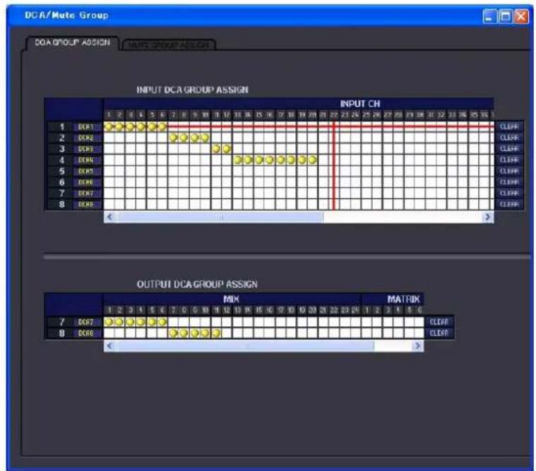
Here you can specify the channels that will be assigned to DCA groups 1–8. The upper part of the screen lets you assign input channels to DCA groups, and the lower part of the screen lets you assign output channels to DCA groups.
Except for the fact that assignments for both input channels and output channels can be made in a single screen, and the fact that the screen can be resized vertically and horizontally, basic operation here is the same as in the PM5D's DCA GROUP ASSIGN screen.
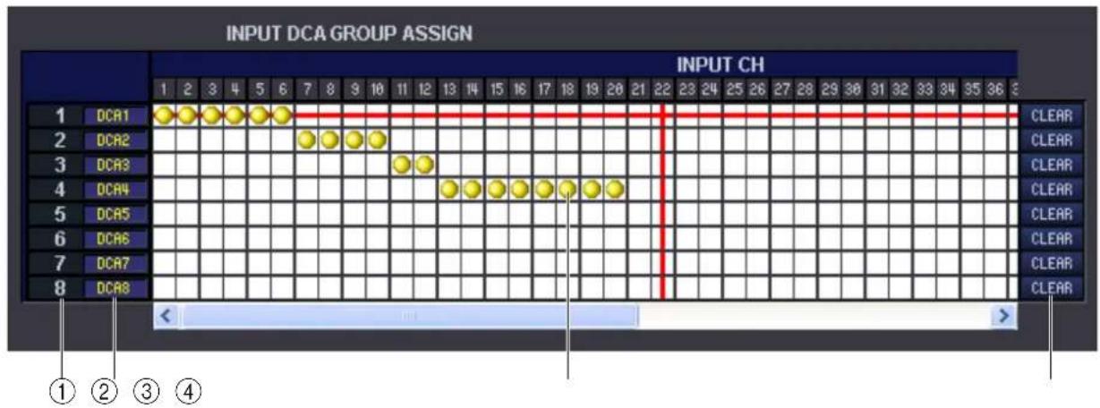
① DCA group
This is the number of the DCA group.
② DCA group name
This is the name of the DCA group. You can also click the mouse on this area to edit the name.
③ Grid
This grid lets you assign channels (horizontal rows) to DCA groups (vertical columns). Currently-patched grids are indicated by a symbol. To enable or disable an assignment, click the desired grid.
④ CLEAR
These buttons clear all input channels and output channels assigned to the corresponding DCA group. When you click one of these buttons a window will appear, asking you to confirm the operation. To execute the Clear operation, click the OK button.
Clicking the CLEAR button for input channel DCA groups 7/8 will not affect the output channel assignments. (The converse also applies.)
MUTE GROUP ASSIGN page
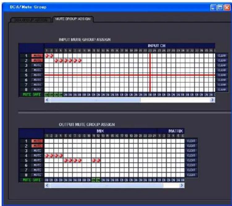
Here you can specify the channels that will be assigned to mute groups 1–8. The upper part of the screen lets you assign input channels to mute groups, and the lower part of the screen lets you assign output channels to mute groups.
Except for the fact that assignments for both input channels and output channels can be made in a single screen, and the fact that the screen can be resized vertically and horizontally, basic operation here is the same as in the PM5D's MUTE GROUP ASSIGN screen.
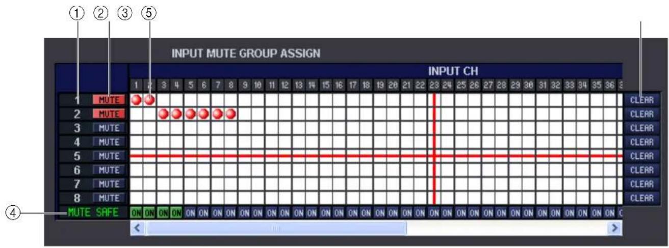
① Mute group
This area shows the mute group number.
② MUTE MASTER (Mute master)
These buttons turn muting on/off for each mute group (common to inputs and outputs).
③ Grid
This grid lets you assign channels (horizontal rows) to mute groups (vertical columns). Currently-patched grids are indicated by a symbol. To enable or disable an assignment, click the desired grid.
④ MUTE SAFE ON (Mute Safe on/off)
These buttons switch Mute Safe on/off for each channel. Channels for which this button is on will be excluded from mute groups.
⑤ CLEAR
These buttons clear all input channels and output channels assigned to the corresponding mute group. When you click one of these buttons a window will appear, asking you to confirm the operation. To execute the Clear operation, click the OK button.
Even if you click the CLEAR button corresponding to an input channel MUTE group 1–8, the output channel assignments will not be affected. (The converse is also the case.)
Scene window
Here you can manage scene memories, and make various settings related to scene recall operations.
This window is divided into SCENE MEMORY, EVENT LIST, RECALL SAFE, and FADE TIME pages. To switch pages, click the tabs shown in the upper part of the window.
SCENE MEMORY page
![Scene SCENE MEMORY EVENT LIST SELECTING RECALL RECALL SAVE PAGE TIME Scene/Resource/PRTS OFF CLOSE SAVE SAVE FOR... No. TITLE PROTECT SEL. RECALL INPUT 001 Scene #01 002 Scene #02 003 [ No Data1 ] 004 [ No Data1 ] 005 Scene #04 006 [ No Data1 ] 007 [ No Data1 ] 008 [ No Data1 ] 009 [ No Data1 ] 010 [ No Data1 ] 011 [ No Data1 ] 012 [ No Data1 ] 013 [ No Data1 ] 014 [ No Data1 ] 015 [ No Data1 ] 016 [ No Data1 ] 017 [ No Data1 ] 018 [ No Data1 ] 019 [ No Data1 ] 020 [ No Data1 ] 021 [ No Data1 ] 022 [ No Data1 ] 023 [ No Data1 ] 024 [ No Data1 ] 025 [ No Data1 ] 026 [ No Data1 ] 027 [ No Data1 ] NOTE: TITLE PROTECT SEL. RECALL INPUT 008 Initial Data ECD 8 LN 001 OverView # 1 002 Scene #01 # 2 003 Scene #02 # 3 004 Scene #03 # 4 005 Scene #04 # 5 006 Scene #05 # 6 007 [ No Data1 ] # -- 008 [ No Data1 ] # -- 009 [ No Data1 ] # -- 010 [ No Data1 ] # -- 011 [ No Data1 ] # -- 012 [ No Data1 ] # -- 013 [ No Data1 ] # -- 014 [ No Data1 ] # -- 015 [ No Data1 ] # -- 016 [ No Data1 ] # -- 017 [ No Data1 ] # -- 018 [ No Data1 ] # -- 019 [ No Data1 ] # -- 020 [ No Data1 ] # -- 021 [ No Data1 ] # -- 022 [ No Data1 ] # -- 023 [ No Data1 ] # -- 024 [ No Data1 ] # -- 025 [ No Data1 ] # -- 026 [ No Data1 ] #VALUE INTERNAL DATA](/content/2026/05/910394/images/a17946e95e60b84ec149236adad2ac1f7f3a7f32d192e667ed1ec213b1311060.jpg)
Here you can edit the PM5D/DSP5D's scene memories. You can also load scene library files from a memory card or from a drive of your computer, and edit them. In this case, you can re-save all scenes to a file after editing, recall just a desired scene, or copy a desired scene to the scene memory of the PM5D/DSP5D itself.
![SceneMemory.PMS OPEN CLOSE SAVE SAVE AS... No. TITLE PROTECT SEL. SELECT RECALL INPUT 001 Scene #01 002 Scene #02 003 [ No Data! ] 004 [ No Data! ] 005 Scene #04 006 [ No Data! ] 007 [ No Data! ] 008 [ No Data! ] 009 [ No Data! ] 010 [ No Data! ] 011 [ No Data! ] 025 [ No Data! ] 026 [ No Data! ] 027 [ No Data! ] 028 [ No Data! ] FILE](/content/2026/05/910394/images/da51997421379e6bca419a2bee017e91dfa8bc637fd08f2d019052673fc33c9d.jpg)
① OPEN (Open a file)
Opens a scene library file located on a drive of your computer.
② CLOSE (Close a file)
Closes the currently-open scene library file.
③ SAVE
Saves the currently-open scene library file on a drive of your computer.
④ SAVE AS (Save as a different name)
Saves the currently-open scene library file under a different name on a drive of your computer.
⑤ File name
Indicates the file name of the currently-open scene library.
⑥ FILE
This area lists the scenes in the file you opened using the OPEN button (①). The list includes the following items.
HINT To view items that are not currently shown, scroll the list to the right. The boundary lines in the center of the window can be dragged toward the right to expand the file list display area as shown below.
![7 8 9 10 11 No. TITLE PROTECT SEL. SELECT RECALL INPUT PATCH LIBRARY OUTPUT PATCH LIBRARY HA 001 Scene #01 1 - InputPatch#01 LINK 1 - OutputPatch#01 1 LINK 002 Scene #02 2 - InputPatch#02 2 - OutputPatch#02 LINK 2 003 [ No Data! ] - [NO DATA!] - [NO DATA!] - - 004 [ No Data! ] - [NO DATA!] - [NO DATA!] - - 005 Scene #04 5 - InputPatch#05 LINK 5 - OutputPatch#05 5 006 [ No Data! ] - [NO DATA!] - [NO DATA!] -](/content/2026/05/910394/images/825dd3784f2de7f72d240af2bde3cb10fbf826bee6cd791624b6d02c3169fd35.jpg)
⑦ No. (Scene number)
This is the scene number 000–500. (The FILE side will begin from 001.)
⑧ TITLE
This is the scene title. You can also double-click this area and edit the title.
⑨ PROTECT
Turns the protection setting on/off for each scene. This area displays a lock icon for protected scenes; these scenes cannot be overwritten, nor their title edited. For the read-only scene 000 or a scene that has been set to read-only on the PM5D itself, this field will indicate “READ.”
⑩ SEL. RECALL (Selective recall)
Switches the selective recall setting on/off for each scene. Selective recall using Safe parameters is enabled for scenes for which this column indicates “SAFE,” and selective recall using Recall parameters is enabled for scenes for which this column indicates “RECALL.”
⑪ Library link
These columns indicates the number, title and [LINK] button of the INPUT PATCH library, OUTPUT PATCH library, and HA library that are linked to each scene. (With the default column width of the list, the library number and LINK button are shown.) You can double-click the numerical area and specify the linked library from the popup menu that appears. The link on/off status can be set using the cell at the right of each library item.
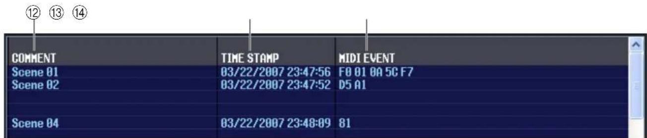
⑫ COMMENT
This column shows the comment assigned to each scene. You can also double-click this column and edit the comment.
⑬ TIME STAMP
Indicates the time at which the scene was last stored, in the format of month/day/year/hours/minutes/seconds. This column is only for display, and cannot be edited.
⑭ MIDI EVENT
This function is found only in PM5D Editor. In this column, the MIDI event that is transmitted from the MIDI OUT connector when the scene is recalled can be viewed and edited in hexadecimal form. To edit a MIDI event, click the two-digit hexadecimal value you want to edit, and choose the desired value from the popup menu that appears.

- If you choose "NOP" from the popup menu, that two-digital hexadecimal value will be ignored.
- If you choose "END" from the popup menu, all subsequent hexadecimal values will be ignored.
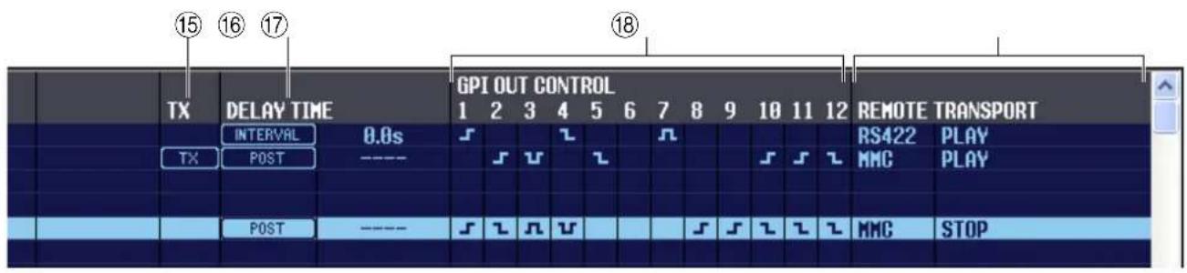
⑮ TX (MIDI event transmission)
This function is found only in PM5D Editor. If you click this column to make the “TX” indication appear, transmission will be enabled for the MIDI event specified for this scene.
⑯ DELAY TIME
This function is found only in PM5D Editor. This specifies the timing at which MIDI Program Changes and MIDI events will be transmitted.
- POST
Program changes and MIDI events will be transmitted after scene recall processing has been completed.
- INTERVAL
Program changes and MIDI events will be transmitted a fixed interval of time after scene recall processing began. The transmission start time can be set in a range of 0.0 seconds through 9.9 seconds.
⑰ GPI OUT CONTROL
This function is found only in PM5D Editor. Specifies the polarity (high-active/low-active) and transmission method (tally/trigger) of the signal that is sent from GPI OUT ports 1–12 when the scene is recalled. You can also click these columns to edit the setting. You can choose from the following settings.
| Display Polarity Transmission method | |
| None Disabled | |
| s | High active Tally |
| l | Low active Tally |
| n | High active Trigger |
| v | Low active Trigger |
⑱ REMOTE TRANSPORT
This function is found only in PM5D Editor. These columns indicate the MMC/RS422 transport command that will be executed when you recall the scene. The left column indicates the protocol (MMC or RS422), and the right column indicates the type of command. You can click an item and choose the desired protocol or command from the popup menu that appears.
![No. TITLE PROTECT SEL. INPUT 000 Initial Data READ 0 LIN 001 Over View 1 002 Scene #01 2 003 Scene #02 SAFE 3 004 Scene #03 4 005 Scene #04 5 006 Scene #05 6 007 [ No Data! ] - - 008 [ No Data! ] - - 009 [ No Data! ] - - 010 [ No Data! ] - - 011 [ No Data! ] - - 012 [ No Data! ] - - 013 [ No Data! ] - - 014 [ No Data! ] - - 015 [ No Data! ] - - 016 [ No Data! ] - - 017 [ No Data! ] - - 018 [ No Data! ] - - 019 [ No Data! ] - - 020 [ No Data! ] - - 021 [ No Data! ] - - 022 [ No Data! ] - - 023 [ No Data! ] - - 024 [ No Data! ] - - 025 [ No Data! ] - - 026 [ No Data! ] - - INTERNAL DATA STORE RECALL CLEAR UNDO PROTECT 20 21 22 23 24 19](/content/2026/05/910394/images/f2943ca2f6e6843532c1a6bc9d6f1c16b8a919adfe7f4eab82e192ce533bf01c.jpg)
⑲ INTERNAL DATA
This area shows the PM5D/DSP5D's scene memory contents. The items displayed are the same as in the FILE list (6).
As desired, you can copy single or multiple scenes between the FILE list and the INTERNAL DATA list, and copy or move them to a different location within a list.
To do this, use the following methods to select the scene(s) that you want to copy or move.
• T o select a single scene
Click the line containing the desired scene.
![No. TITLE PROTECT SEL. 008 Initial Data READ 001 Over View 002 Scene #01 003 Scene #02 SAFE 004 Scene #03 005 Scene #04 006 Scene #05 007 [ No Data! ] 008 [ No Data! ] 009 [ No Data! ]](/content/2026/05/910394/images/1d206581c69407fbd9bec86cafd256956eaa26a82cf4f6226b8ac2bd4ab7adb2.jpg)
• T o select multiple consecutive scenes
Click the first scene to select it; then hold down the
![No. TITLE PROTECT SEL. 000 Initial Data READ 001 Over View 002 Scene #01 003 Scene #02 004 Scene #03 005 Scene #04 006 Scene #05 007 [ No Data! ] 008 [ No Data! ] 009 [ No Data! ]](/content/2026/05/910394/images/69ae84ec54327e67ac2e9ddca6cb34c3edcd0c13a7e828eb715061add276d64d.jpg)
• T o select multiple non-consecutive scenes
Click the first scene; then hold down the
When you have selected the scene(s) that you want to move or copy, drag them to the desired location in the other list (if you're copying between lists) or in the same list (if you're copying/moving within the same list).
![No. TITLE PROTECT SEL. 800 Initial Data READ 801 Over View 802 Scene #01 803 Scene #02 804 Scene #03 805 Scene #04 806 Scene #05 807 [ No Data! ] 808 [ No Data! ] 809 [ No Data! ]](/content/2026/05/910394/images/2f9c6cfbe92d5a9c2fe115c4bc6bede40f1aa78a30aff0e654c60cb8aff0ad2e.jpg)
• T o copy scenes (overwriting the destination)
Drag the copy-source scene(s) to the desired line in the other list or to another line in the same list. At this time, a ▶ symbol will appear at the right of the scene number.
When you release the mouse in this state, a dialog box will appear, asking you to confirm the Save operation. If you click the OK button, the copy-source scene(s) will be overwritten onto the copy-destination scenes, and the copy-source scene(s) will remain unchanged. (If
![No. TITLE PROTECT SEL. 000 Initial Data REAO 001 Over View 002 Scene #01 003 Scene #02 004 Scene #03 005 Scene #04 006 Scene #05 007 [ No Data! ] 008 [ No Data! ] 009 [ No Data! ]](/content/2026/05/910394/images/546936518e3450b85a00e4803e77c53727f2cf7c85d4b7724e260a6a957ba6cc.jpg)
the copy-source selection contains multiple scenes, the data will be overwritten onto consecutive scenes starting at that scene.)
• T o move scenes
Within the same list, you can move the selected scene(s) to another location to rearrange the order of the scenes in the list. To do this, drag the selected scene(s) to a location between two other lines in the same list. At this time, a symbol will appear between the lines.
When you release the mouse button in this state, the selected scene(s) will move to that location, and the scene numbers will also change accordingly. (If the move-source selection contains multiple scenes, those scenes will be inserted consecutively at the location you specify.)
![No. TITLE PROTECT SEL. 000 Initial Data READ 001 Over View 002 Scene #01 003 Scene #02 004 Scene #03 005 Scene #04 006 Scene #05 007 [ No Data! ] 008 [ No Data! ] 009 [ No Data! ]](/content/2026/05/910394/images/dbc0d2a17616dccd61d20369701f4120b1b924807c52154ab1cdf88149372b0d.jpg)
⑳ STORE
Stores the current settings to the scene that is selected in the list.
②1 RECALL
Recalls the settings of the scene selected in the list.
22 CLEAR
Clears the scene(s) selected in the list. (The title of the cleared scene(s) will be reset to [No Data!].)
23 UNDO
Cancels the last-performed scene recall, store, copy, or move operation.
⑳ PROTECT
Turns on the Protect setting for the scene(s) selected in the list.
![Scene SCENE MEMORY EVENT LIST SELECTIVE RECORDS RECALL SAFE FIRE TIME No. EVENT NUMBER SCENE TITLE 000 00:05:50.00 000 Initial Data 001 [MENJAL] 002 00:10:50.00 001 SCENE-001 003 +105.79FC 002 SCENE-002 004 +413.59C 003 SCENE-003 005 [MENJAL] 004 SCENE-004 006 00:30:00.00 005 SCENE-005 007 008 009 010 011 012 013 014 015 016 017 018 019 020 021 022 023](/content/2026/05/910394/images/fb088cad2cc3e2a9210fa342ed098af2b7754816aedddfedbd8feb30ac3703a4.jpg)
In this page you can see how the scenes registered in the PM5D's EVENT LIST screen will be switched according to the progression of time code or according to the elapsed time since the most recent Recall operation.
NOTE • This page functions as a viewer of the PM5D's EVENT LIST screen. You cannot register or recall events from within this page.
- In order for the EVENT LIST page to be synchronized with the EVENT LIST screen of the PM5D itself, PM5D Editor must be synchronized with the PM5D.
• The DSP5D does not have this function.
![① ② ③ No. EVENT TRIGGER SCENE TITLE 000 00:05:50.00 000 Initial Data 001 [MANUAL] 002 00:10:50.00 001 SCENE#01 003 105.7SEC 002 SCENE#02 004 413.5SEC 003 SCENE#03 005 [MANUAL] 004 SCENE#04 006 00:30:00.00 005 SCENE#05 007 008](/content/2026/05/910394/images/208b60ddbc7839434a8dc5ed278848dd9fd017f332c7467d6da27cb09f7b3839.jpg)
① No. (Number)
This column indicates the number of each event registered in the event list.
② EVENT TRIGGER
This column indicates the recall condition specified for each event. This shows an hour:minute:second:frame value for scenes that will be recalled at a specific time code, a value in seconds for scenes that are recalled after a specified time has elapsed after the preceding event was executed, or [MANUAL] for scenes that are recalled manually.
③ SCENE TITLE
This column indicates the number and title of the scene that will be recalled.
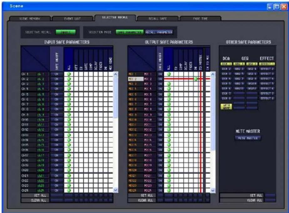
Here you can make settings for the Selective Recall function, which allows you to exclude specific parameters/channels of each scene from recall operations, or conversely to recall only specific parameters/channels.
Display and operations within this page are the same as in the SELECTIVE RECALL screen of the PM5D itself.
RECALL SAFE page
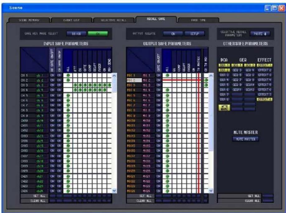
Here you can make settings for the Recall Safe function that excludes only specific channels from recall operations of all scenes.
The display and operations within this page are the same as in the PM5D's RECALL SAFE screen.
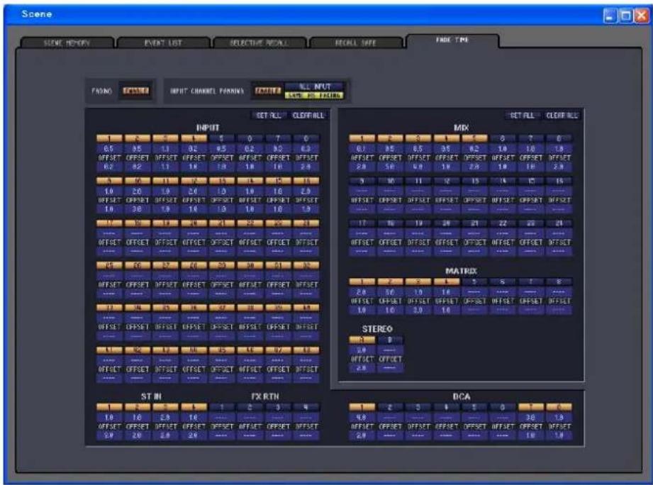
Here you can make settings for the Fade function that adjusts the time over which fader and pan will reach their new values when a scene is recalled. The settings of the Fade function are independent for each scene.
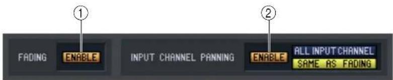
① FADING ENABLE (Fade function enable/disable)
Switches the Fade function for fader levels between enabled and disabled.
② INPUT CHANNEL PANNING ENABLE (Input channel panning enable/disable)
Switches the Fade function for input channel pan (balance) parameters between enabled and disabled. If this button is on, you can use the two buttons located at the right to select the input channels to which this setting will apply.
- When the ALL INPUT CHANNEL button is on
The Fade function will apply to the pan (balance) parameter of all input channels.
- When the SAME AS FADING button is on
The Fade function will apply to the pan (balance) parameter of input channels for which the Fade function is turned on in ⑤.
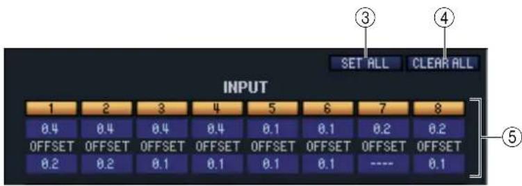
③ SET ALL
This button lets you enable all Fade function settings with one click. This can be operated independently for all input channels and DCA groups, or for all output channels.
④ CLEAR ALL
This button lets you disable all Fade function settings with one click. This can be operated independently for all input channels and DCA groups, or for all output channels.
⑤ Channel settings
Here you can specify the Fade function on/off status, the fade time, and the offset time for each input channel, output channel, and DCA group.
To edit the fade time or offset time value, click the numerical box and drag upward or downward.
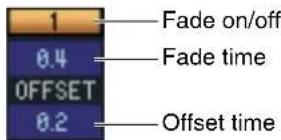
Library window
![Library INPUT ON OUTPUT ON DATE COMP INPUT TO OUTPUT ON INPUT SWITCH OUTPUT SWITCH RESET NEW NO. HOTGEUPHS OPEN CLOSE SAVE SPAC NO. No. TITLE 001 Introduction 002 Scene1-1 003 Scene1-2 004 Scene1-3 005 Scene1-4 006 Intermission1-2 007 Scene2-1 008 Scene2-2 009 Scene2-3 010 Scene2-4 011 Scene2-5 012 Scene2-6 013 Scene2-7 014 Intermission2-3 015 Scene3-1 016 Scene3-2 017 Scene3-3 018 Scene3-4-1 019 Scene3-4-2 020 Scene3-4-3 021 Scene3-5 022 Finale 023 [ No Data ] 024 [ No Data ] 025 [ No Data ] 026 [ No Data ] 027 [ No Data ] 029 [ No Data ] No. TITLE 009 Initial Date ICO 01 Introduction 002 Scene1-1 003 Scene1-2 004 Scene1-3 005 Scene1-4 006 Intermission1-2 007 Scene2-1 008 Scene2-2 009 Scene2-3 010 Scene2-4 011 Scene2-5 012 Scene2-6 013 Scene2-?- 014 Intermission2-3 015 Scene3-1 016 Scene3-2 017 Scene3-3 018 Scene3-4-1 019 Scene3-4-2 020 Scene3-4-3 021 Scene3-5 022 Finale 023 [ No Data ] 024 [ No Data ] 025 [ No Data ] 0 26 [ No Data ] 027 [ No Data ] INTERNAL DATA](/content/2026/05/910394/images/e59955c8ed913fc068654a0655bb4a9233a0af749bf54af66c17bbd9bc00de10.jpg)
Here you can edit the PM5D/DSP5D's various libraries. You can also load library files that were saved on a drive of your computer, edit the order or title of library items, recall the desired library data, or copy desired library data to a library within the PM5D/DSP5D.
This window is divided into INPUT CH, OUTPUT CH, GATE, COMP, INPUT EQ, OUTPUT EQ, INPUT PATCH, OUTPUT PATCH, EFFECT, GEQ, and HA pages; to switch pages, click the tabs located at the top of the window. The editing procedure is the same in all pages. The explanation here uses the example of the OUTPUT EQ page.
![No. TITLE 004 Total EQ 1 005 Total EQ 2 006 Total EQ 3 007 Total EQ 4 008 Total EQ 5 009 [ No Data! ] 010 [ No Data! ] 011 [ No Data! ] 012 [ No Data! ] 013 [ No Data! ] 014 [ No Data! ] 021 [ No Data! ] 028 [ No Data! ] 029 [ No Data! ] 030 [ No Data! ] 031 [ No Data! ]](/content/2026/05/910394/images/f27ce1e3324486f2008be01b5721f61a680583fe5e7b1973a68fd4fe80956be3.jpg)
① OPEN (Open a file)
Opens a library file located on a drive of your computer. Use this when you want to edit library data that you've saved on a memory card.
② CLOSE (Close a file)
Closes the currently-open library file.
③ SAVE
Saves the currently-open scene library file on a drive of your computer.
④ SAVE AS (Save under a different name)
Saves the currently-open library file under a different name on a drive of your computer.
⑤ File name
Indicates the file name of the currently-open library.
⑥ FILE
This list shows the contents of the data in the library file you opened using the OPEN button (①). The list includes the following items.
![7 8 9 No. TITLE 000 Initial Data READ 001 Introduction 002 Scene1-1 003 Scene1-2 004 Scene1-3 005 Scene1-4 006 Intermission1-2 007 Scene2-1 008 Scene2-2 009 Scene2-3 010 Scene2-4 011 Scene2-5 012 Scene2-6 013 Scene2-7 014 Intermission2-3 015 Scene3-1 016 Scene3-2 017 Scene3-3 018 Scene3-4-1 019 Scene3-4-2 020 Scene3-4-3 021 Scene3-5 022 Finale 023 [ No Data! ] 024 [ No Data! ] 025 [ No Data! ] 026 [ No Data! ] 027 [ No Data! ] INTERNAL DATA OUTPUT EO PEQ STORE RECALL 1 2 3 4 5 6 7 8 9 18 11 12 13 14 15 16 17 18 19 28 CLEAR UNDO ⑪ ⑫ ⑬](/content/2026/05/910394/images/f0e3bc620ffa0e56c6791921820b506ac3f5660c0e3430fa8b8be2f5341f5f4a.jpg)
⑦ No. (Number)
This area shows the library number.
⑧ TITLE
This column indicates the title assigned to each library item. You can also double-click this area and edit the title.
⑨ READ ONLY
Read-only data is indicated by "READ" displayed in this column.
If the PREFERENCE screen LINKED LIBRARY PROTECTION is also protecting the library (INPUT PATCH/OUTPUT PATCH/HA) that is linked to a protected scene, a lock icon is shown in this field. The lock icon is not shown for other libraries.
⑩ INTERNAL DATA
This area shows the PM5D/DSP5D's library contents. The items displayed are the same as in the FILE list (⑥).
As desired, you can copy single or multiple items between the FILE list and the INTERNAL DATA list, and copy or move them to a different location within a list. The procedure is the same as in the SCENE MEMORY page of the Scene window ( p.60).
⑪ OUTPUT EQ (output equalizer)
This specifies Output EQ as the library recall-source and save-destination. This is shown in the OUTPUT EQ window.
⑫ PEQ (parametric equalizer)
This specifies PEQ as the library recall-source and save-destination. This is shown in the OUTPUT EQ window.
⑬ STORE
Stores the current settings to the data item that is selected in the list.
⑭ RECALL
Recalls the data item that is selected in the list.
⑮ Module number
These buttons select the module number that will be the subject of store/recall operations. These are shown in the OUTPUT EQ (only if PEQ is selected), Effect, and GEQ windows.

CLEAR
Clears the data item(s) selected in the list. (The title of the cleared item(s) will be reset to [ No Data! ].)

UNDO
Cancels the last-performed library store, copy, or move operation.
Meter window
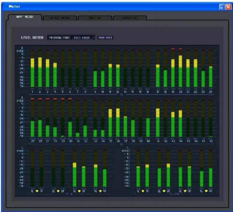
bar_stacked
LEVEL METER | Measurement | IL | ♥ | F | CL | ♥ | F | |---|---|---|---|---|---|---| | 1 | -10 | -15 | -10 | -15 | -20 | -25 | | 2 | -10 | -15 | -10 | -15 | -20 | -25 | | 3 | -10 | -15 | -10 | -15 | -20 | -25 | | 4 | -10 | -15 | -10 | -15 | -20 | -25 | | 5 | -10 | -15 | -10 | -15 | -20 | -25 | | 6 | -10 | -15 | -10 | -15 | -20 | -25 | | 7 | -10 | -15 | -10 | -15 | -20 | -25 | | 8 | -10 | -15 | -10 | -15 | -20 | -25 | | 9 | -10 | -15 | -10 | -15 | -20 | -25 | | 10 | -10 | -15 | -10 | -15 | -20 | -25 | | 11 | -10 | -15 | -10 | -15 | -20 | -25 | | 12 | -10 | -15 | -10 | -15 | -20 | -25 | | 13 | -10 | -15 | -10 | -15 | -20 | -25 | | 14 | -10 | -15 | -10 | -15 | -20 | -25 | | 15 | -10 | -15 | -10 | -15 | -20 | -25 | | 16 | -10 | -15 | -10 | -15 | -20 | -25 | | 17 | -10 | -15 | -10 | -15 | -20 | -25 | | 18 | -10 | -15 | -10 | -15 | -20 | -25 | | 19 | -10 | -15 | -10 | -15 | -20 | -25 | | 20 | -10 | -15 | -10 | -15 | -20 | -25 | | 21 | -10 | -15 | -10 | -15 | -20 | -25 | | 22 | -10 | -15 | -10 | -15 | -20 | -25 | | 23 | -10 | -15 | -10 | -15 | -20 | -25 | | 24 | -10 | -15 | -10 | -15 | -20 | -25 | | 25+Here you can view the signal levels within the PM5D/DSP5D, or the amount of gain reduction produced by the internal compressors and gates. This lets you check signal presence, overload status, and compressor/gate operation from your computer.
This window is divided into INPUT METER, OUTPUT METER, INPUT GR, and OUTPUT GR pages. To switch pages, click the tabs shown in the upper part of the window.
The displayed content and operation in each page is the same as the various screens of the PM5D's METER function.
NOTE In order to view the PM5D/DSP5D's signal levels in the Meter window, make sure that PM5D/DSP5D Editor and the PM5D/DSP5D itself are synchronized.
Timecode Counter window
This window displays the time code (LTC, MTC) that the PM5D itself is receiving or generating, in units of hours/minutes/seconds/frames. This is the same time code as displayed in the PM5D's fixed display screen and in the EVENT LIST screen.
NOTE
• The DSP5D does not have this function.
- In order for the Timecode Counter window to display the time code that the PM5D itself is receiving/ generating, PM5D Editor and the PM5D must be synchronized.
Sync window
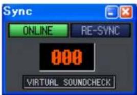
Synchronization between the PM5D/DSP5D itself and PM5D/DSP5D Editor can be switched on/off in this window. This has the same function as the [Synchronization] menu. Click the ONLINE button to switch to off-line, or click the OFFLINE button to switch to on-line. If you click the RE-SYNC button, the Synchronization dialog box will appear (→ p.5). The current scene number and the VIRTUAL SOUNDCHECK status are also shown.
Preference window
In this window you can make PM5D/DSP5D preference settings.
Choose [Windows] → [Utility] → [Preference] to access this window.
![Preference STORE/RECALL LINKED LIBRARY PROTECTION ON STORE CONFIRMATION ON RECALL CONFIRMATION ON PATCH PATCH CONFIRMATION ON STEAL PATCH CONFIRMATION ON GATE/COMP GR METER ON/OFF LINK ON DCA DCA MUTE TARGET POST ONLY WARNING DISPLAY TIME CODE DROP ON DIGITAL I/O ERROR ON MIDI I/O ERROR ON SOFTWARE VERSION SYSTEM VERSION V2.00 LCD V2.00 MAIN [LD] V1.82 MAIN [PR] V2.00 PANEL [L] V2.00 PANEL [R] V2.00 AD IN 1-8 V1.82 AD IN 9-16 V1.82 AD IN 17-24 V1.82 AD IN 25-32 V1.82 AD IN 33-40 V1.82 AD IN 41-48 V1.82 BATTERY OK ① ② ③ ④ ⑤ ⑥ ⑦](/content/2026/05/910394/images/2f574260c766c3cdb19a057594fd2312826d3ec3aea9a9537981e6bae778c767.jpg)
① STORE/RECALL
Here are on/off switches for options related to storing and recalling scenes. You can specify the following options.
• LINKED LIBRARY PROTECTION
If this button is on, it will not be possible to overwrite or delete a library that is linked to a protected scene. This option lets you prevent the contents of a protected scene from being affected by editing a library.
- STORE CONFIRMATION
- RECALL CONFIRMATION
If these buttons are on, a confirmation message will appear when a Store or Recall operation respectively is executed.
② PATCH
Here are on/off switches for options related to patch operations. You can specify the following options.
- PATCH CONFIRMATION
If this button is on, a confirmation message will appear when you modify the input patch or output patch.
• STEAL PATCH CONFIRMATION
If this button is on, a confirmation message will appear when you modify a location that is already patched to an input patch or output patch.
③ GATE/COMP (gate / compressor)
Here is an on/off switch for the following gate/compressor option.
• GR METER ON/OFF LINK
If this button is on, the GR meter will not show the amount of reduction for gates/compressors that are currently off.
④ DCA MUTE TARGET
When the send position to the MIX bus is PRE FADER, this specifies whether the DCA [MUTE] keys will mute the send to the MIX bus. If you specify “POST ONLY,” the PRE FADER signal will not be muted. If you specify “PRE & POST,” the signal will be muted regardless of the send position.
⑤ WARNING DISPLAY
This selects whether a warning will be displayed when the following problems occur.
• TIME CODE DROP
This function is found only in PM5D Editor. When a drop occurs in the time code (LTC, MTC) being received from an external source.
• DIGITAL I/O ERROR
When a DIO error is detected.
- MIDI I/O ERROR
This function is found only in PM5D Editor. When a MIDI error is detected.
⑥ SOFTWARE VERSION
This indicates the version of the PM5D/DSP5D firmware.
If offline, this is shown as ----.
⑦ BATTERY
This shows the approximate state of the internal battery voltage (remaining battery amount).
The voltage status is indicated as follows.

User Defined Keys Setup window
In this window you can assign functions to the PM5D console's user-defined keys from within the editor.
Choose [Windows] → [Utility] → [User Defined Keys Setup] to access this window.
DSP5D Editor does not have a corresponding window.
When you click the button for the desired user-defined key, an editing screen will appear, allowing you to assign a function. However unlike operations on the PM5D itself, you won't be able to execute the assigned function.
If you synchronize Console -> PC, the settings of the PM5D itself will be reflected in PM5D Editor.
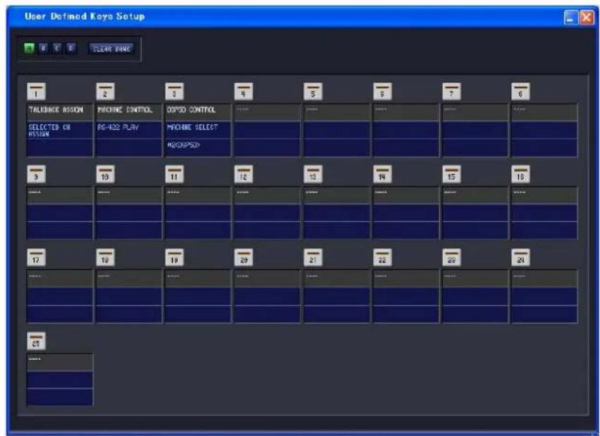
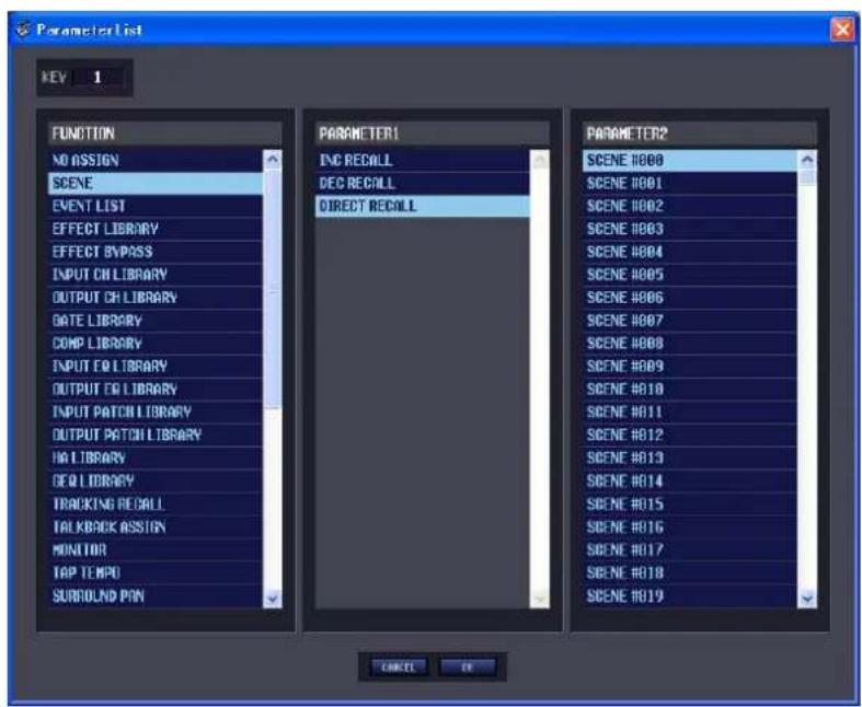
Fader Mode Assign window
In this window of the editor you can freely assign functions to the faders just as in the PM5D's FADER ASSIGN screen.
Choose [Windows] [Utility] [Fader Mode Assign] to access this window. However unlike the FADER ASSIGN screen on the PM5D itself, you won't be able to execute the assigned function.
If you synchronize Console -> PC, the settings of the console will be reflected in PM5D Editor.
DSP5D Editor does not have a corresponding window.
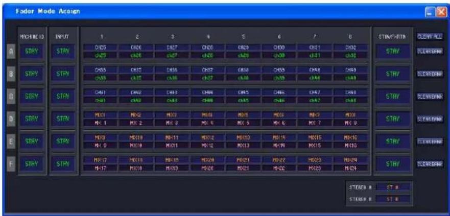
- CLEAR ALL
Initializes the fader assign settings.
- CLEAR BANK
Initializes the fader assign settings in units of BANKS (A–F).
Output Port Att window
In this window you can specify the attenuator value and switch phase reversal on/off for the output ports of the PM5D/DSP5D from within the editor.
Choose [Windows] -> [System] -> [Output Port Att] to access this window.
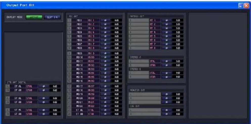
Word Clock window
In this window of the editor you can edit and view the DSP5D's word clock settings.
Choose [Windows] → [System] → [Word Clock] to access this window.
DSP5D Editor does not have a corresponding window.
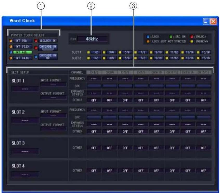
① MASTER CLOCK SELECT
This selects the master clock that will be used; either the internal clock or an external clock received via a connector or slot. This setting will determine the sampling rate at which the DSP5D will operate. You can select the following items.
| Indication (button) Content | |
| INT 96k | DSP5D's internal clock (sampling rate = 96 kHz) |
| INT 88.2k | DSP5D's internal clock (sampling rate = 88.2 kHz) |
| INT 48k | DSP5D's internal clock (sampling rate = 48 kHz) |
| INT 44.1k | DSP5D's internal clock (sampling rate = 44.1 kHz) |
| W.CLOCK IN | Word clock supplied from the WORD CLOCK IN connector |
| CASCADE IN | Word clock supplied from the CASCADE IN (D-sub) connector |
| CASCADE IN | Word clock supplied from the CASCADE IN (RJ-45) connector |
| SLOT 1-SLOT 2 | Clock data from a digital audio signal supplied via a digital I/O card in slots 1–2 (can be selected in two-channel units) |
The status (operating condition) of each clock is indicated by the color of the Symbol located at the left of each button. Each color has the following significance.
- LOCK ( )
This indicates that a clock synchronized with the source selected in ① is being input. If an external device is connected to the corresponding connector/slot, input/output is occurring correctly between that device and the DSP5D. If the sampling rate is close, this status may be shown even if the source is not synchronized.
- UNLOCK ( )
This indicates that a valid clock is not being input. If an external device is connected to the corresponding connector, input/output cannot occur correctly between that device and the DSP5D.
- LOCK, but NOT SYNC'ED ( )
A valid clock is being input, but is not synchronized with the clock source selected in ①. If an external device is connected to the corresponding connector, input/output cannot occur correctly between that device and the DSP5D.
- UNKNOWN ( )
This indicates that the clock status cannot be detected because no external device is connected or because there is no valid clock input. You will be able to select this connector/slot, but correct synchronization cannot occur until a valid connection is established.
- SRC ON ( )
This is a special status limited to SLOT 1–2, and indicates that the SRC (Sampling Rate Converter) of the corresponding channel is enabled. This means that input/output with the DSP5D can occur correctly even when not synchronized.
NOTE
- Noise may be produced from the output jacks when you change the word clock setting. To protect your speakers, you must turn down the power amp output before you change the word clock setting.
- If you attempt to select a channel for which SRC is On as the word clock master, a warning message will inform you that the sampling rate converter will be disabled.
② Fs (sampling frequency)
This indicates the sampling frequency at which the DSP5D is operating. This will indicate “UNLOCKED” if synchronization is not currently achieved, such as immediately after you’ve switched the master clock.
③ SLOT SETUP
- SLOT number and card type
This shows the type of digital I/O card installed in slots 1–2, and CASCADE for slots 3/4.
- INPUT FORMAT (input signal format) / OUTPUT FORMAT (output signal format)
Here you can select one of the following as the method by which signals will be transmitted and received via a digital I/O card installed in the slot when the DSP5D is operating at a high sampling rate (88.2/96 kHz).
SINGLE
Use this setting if a device operating at the conventional 44.1/48 kHz is connected, and you want to operate it with the original channel count. The sampling frequency will be converted for each channel of the digital I/O card, and transmitted/received at half the sampling rate of the DSP5D (44.1/48 kHz). (This setting can be selected only for slots in which a digital I/O card that does not support 96 kHz is installed.)
DOUBLE SPEED
Use this setting if a device operating at a high sampling rate (88.2/96 kHz) is connected, and you want to transmit and receive high sampling rate audio signals without change. (This setting can be selected only for slots in which a digital I/O card that supports 96 kHz is installed.)
DOUBLE CHANNEL
Use this setting if a device operating at the conventional 44.1/48 kHz is connected, and you want it to handle high sampling rate (88.2/96 kHz) signals. Two channels of signals at half the DSP5D's sampling rate (44.1/48 kHz) will be combined and transmitted/received as a high sampling rate mono signal. (The number of usable channels will be halved.)
• FREQUENCY (sampling rate)
This indicates the sampling rate of the signal being input to the channels of the digital I/O card, in units of two channels.
- SRC (sampling rate converter)
These buttons switch the sampling rate converter on/off in units of two channels. This is available only for slots in which a digital I/O card containing a sampling rate converter is installed.
• EMPHASIS STATUS
This indicates whether emphasis processing is being applied to the input signal, in units of two channels. This is shown only for slots in which a digital I/O card is installed.
• DITHER
This indicates the number of bits for which dithering will be applied to the input signal, in units of two channels. When you click this with the mouse, a popup will appear, allowing you to select either OFF, 16 bit, 20 bit or 24 bit. Select the desired number of bits for dithering.
Oscillator window
In this window of the editor you can edit and view the DSP5D's oscillator status.
Choose [Windows] → [Monitor] → [Oscillator] to access this window.
PM5D Editor does not have a corresponding window.
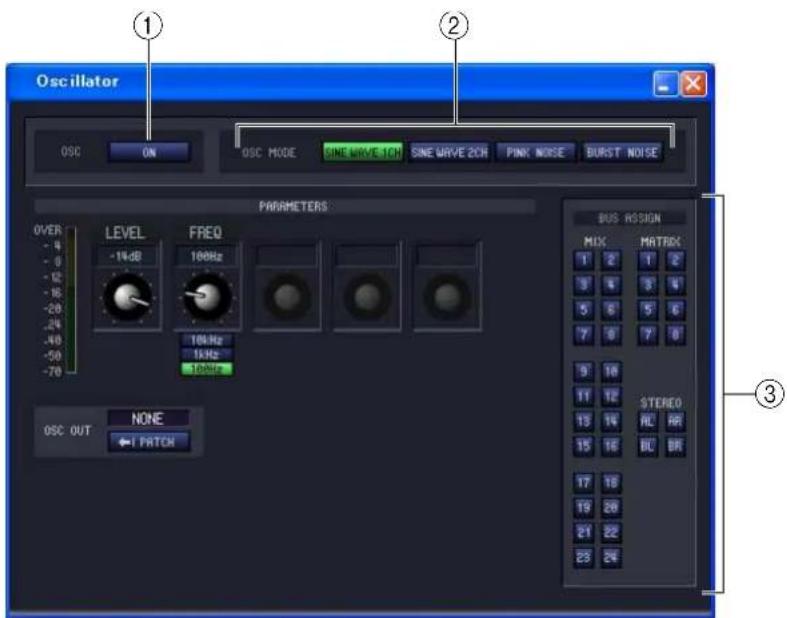
For SINE WAVE 2CH For PINK NOISE For BURST NOISE
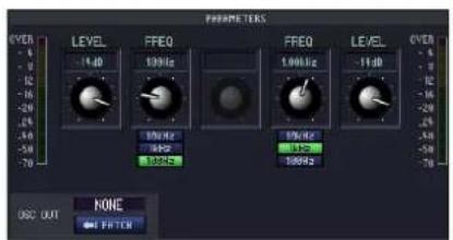
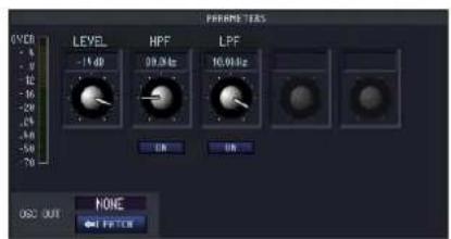
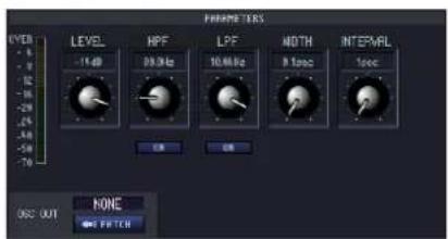
① OSC ON/OFF (oscillator on/off)
This switches the oscillator on/off.
② OSC MODE (oscillator mode)
Here you can select from the following choices of waveform or noise that the oscillator will produce.
SINE WAVE 1CH ..... Sine wave x 1 channel
SINE WAVE 2CH .....Sine wave x 2 channels
PINK NOISE......Pink noise
BURST NOISE ......Burst noise (intermittently output pink noise)
③ PARAMETERS
Specify the following items according to your choice in ②.
• LEVEL
This knob adjusts the output level of the oscillator. The range is -96 dB to 0 dB. The output level is shown by the level meter located beside.
- FREQ (frequency)
Here you can specify the frequency of the sine wave that is output by the oscillator. Use the knob to specify a frequency in the range of 20 Hz–20 kHz. (The current setting is shown by the numerical box located above the knob.) You can select a preset frequency by clicking one of the 10 kHz / 1 kHz / 100 Hz buttons.
HINT If SINE WAVE 2CH is selected, the level and frequency of each channel can be set independently.
- HPF (high pass filter) / LPF (low pass filter)
Here you can make settings for the HPF/LPF that will process the pink noise or burst noise. The upper knob sets the cutoff frequency (20 Hz–20 kHz), and the lower button turns it on/off.
- WIDTH/INTERVAL
If burst noise is selected, these specify the length of the actual noise (WIDTH), and the length of the silent interval between noise bursts (INTERVAL).
The range for WIDTH is 0.1–10 sec, and the range for INTERVAL is 1–30 seconds. (The current setting is shown by the numerical box located above the knob.)
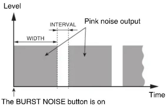
- OSC OUT (oscillator direct output)
This indicates the output jack or slot channel from which the oscillator signal will be directly output. To change the output destination, click the PATCH button to access the OUTPUT PATCH window.
If SINE WAVE 2CH is selected, the L-channel of the oscillator will be output from the oscillator direct output.
- BUS ASSIGN
Here you can select the bus that will output the sine wave or noise. (Multiple choices are allowed.)
MIX 1–24 ...... MIX buses 1–24
MATRIX 1-8...... MATRIX buses 1-8
AL/AR...... STEREO A bus L/R channels
BL/BR...... STEREO B bus L/R channels
If SINE WAVE 2CH is selected, the L-channel of the oscillator will be output from the odd-numbered bus or the L jack, and the R-channel of the oscillator will be output from the even-numbered bus or the R jack.
Cue/Solo window
In this window of the editor you can edit and view the cue and solo status of the PM5D/DSP5D.
Choose [Windows] → [Monitor] → [Cue/Solo] to access this window.
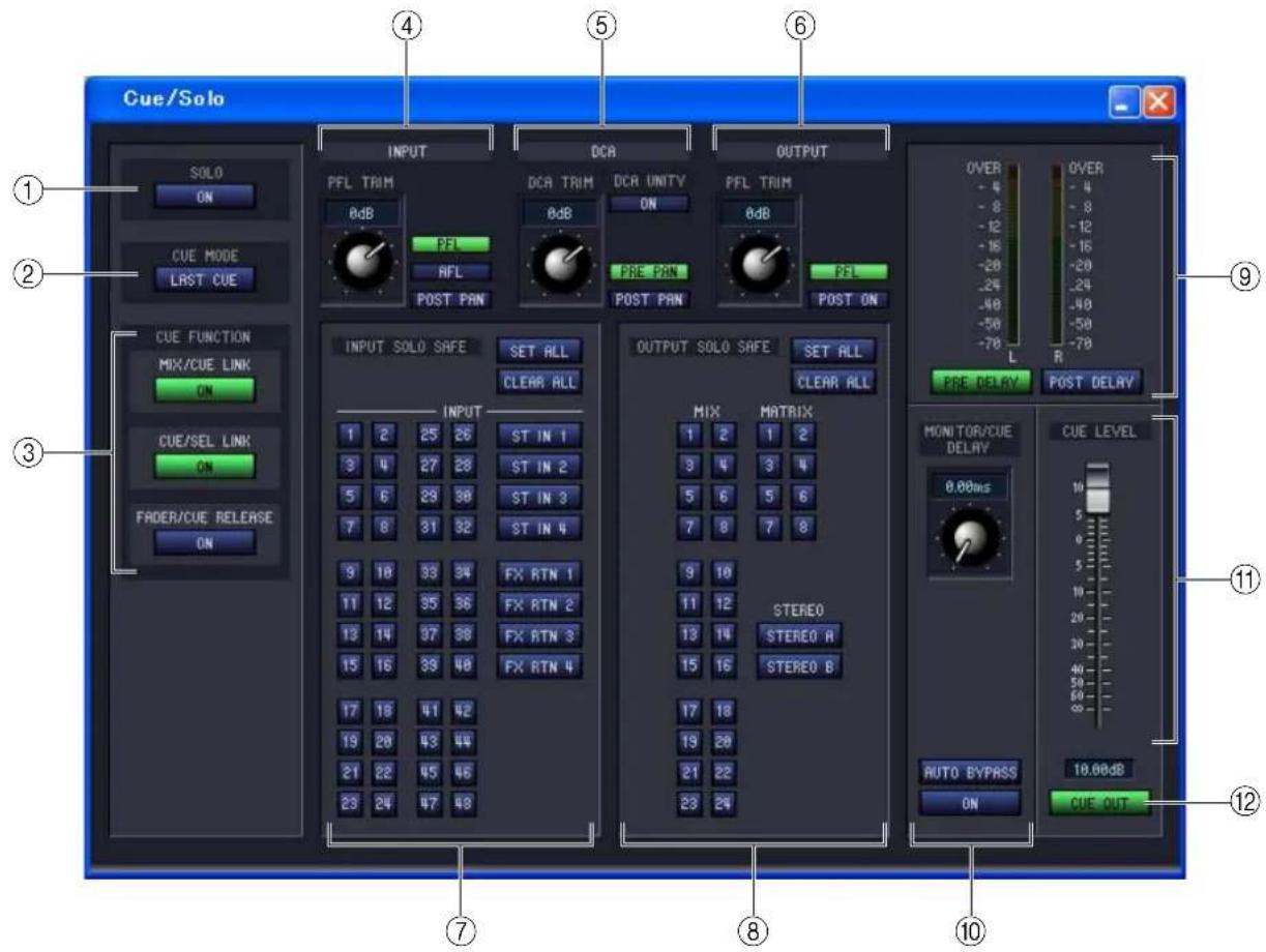
① SOLO ON/OFF
This button selects either CUE MODE or SOLO mode as the monitoring method when the [CUE] key is used. If you turn this button on, a confirmation message will appear. Each mode operates as follows.
• CUE mode (SOLO ON/OFF button is off)
The signal of the channel whose [CUE] key is pressed will be sent to the dedicated CUE bus, and monitored via the CUE bus from the CUE OUT jacks. This mode allows you to monitor the signal of the desired channel without affecting other buses.
• SOLO mode (SOLO ON/OFF button is on)
If you solo an input, the Solo function will be enabled, and only the signal of the channel whose [CUE] key is pressed will be sent to the MIX, MATRIX, and STEREO A/B buses; the other channels will be muted. If you solo an output, only that channel will be on. The signal of the channel whose [CUE] key is pressed can also be monitored via the CUE OUT jacks.
② CUE MODE
This button selects one of the following two modes of operation for when the [CUE] key of more than one channel is pressed. If it is off, operation will be in MIX CUE mode.
- MIX CUE mode
You can monitor the more than one channels or DCA groups whose [CUE] keys are turned on within the same CUE group.
NOTE
- You cannot simultaneously turn on [CUE] keys of differing groups. The CUE group to which the last-pressed [CUE] key belongs will be on, and signals of that CUE group can be monitored.
- If you press the [CUE] key of a paired channel, both channels will be on.
- LAST CUE mode
Only the channel or DCA group that was most recently selected by its [CUE] key will be monitored.
③ CUE FUNCTION
Here you can turn various cue-related functions on/off. The following functions are available.
• MIX CUE LINK
This specifies whether cue operation will be linked with MIX channel selection. If this button is on, pressing the already-selected [MIX] key in the panel ENCODER MODE section will simultaneously cause the [CUE] key of that channel to light. DSP5D Editor does not have this button.
- CUE/SEL LINK
This specifies whether CUE operation will be linked with channel selection. If this button is on, pressing the [CUE] key of the desired channel will simultaneously select that channel, and its [SEL] key will light.
• F ADER/CUE RELEASE
This specifies whether cue operation will be limited according to the fader position. If this button is on, raising the fader from the - position of a channel whose [CUE] key is lit will defeat cue. For channels whose fader is above - , you will be unable to perform cue operations. (Pressing the [CUE] key will not do anything.) This means that cue can be turned on only if the fader is at - .
④ INPUT
Here you can select the position from which the cue signal is taken for input channels.
PFL (pre fader listen) ..... Immediately before the fader
AFL (after fader listen)... Immediately after the fader
POST PAN...... Immediately after pan
If you select PFL, you can also use the knob located at the left to adjust the output level in a range of -20 dB to +10 dB.
⑤ DCA
Here you can make settings for the cue output of DCA groups.
• DCA TRIM
Adjust the level of the cue output for DCA groups, in a range of -20 dB to +10 dB.
• DCA UNITY
If this button is on, pressing a DCA [CUE] key will always monitor the corresponding DCA group at unity gain (the same level as when the DCA fader is at 0 dB).
HINT
- If you leave the DCA UNITY button on, you will always be able to monitor the desired DCA group even if that DCA group is muted or if its DCA fader is lowered.
- The value specified by the DCA TRIM knob is valid even when the DCA UNITY button is on. (In this case, the DCA TRIM knob specifies an offset value relative to unity gain.)
- PRE PAN/POST PAN
This selects whether you will be monitoring the signal immediately before the pan (if the PRE PAN button is on) or the signal immediately after the pan (if the POST PAN button is on) when you turn on a DCA [CUE] button.
⑥ OUTPUT
Here you can select the position from which the cue signal is taken for output channels.
PFL (pre fader listen) ..... Immediately before the fader
POST ON...... Immediately after the [ON] key
If you select PFL, you can also use the knob located at the left to adjust the output level in a range of -20 dB to +10 dB.
⑦ INPUT SOLO SAFE
Here you can select the input channels that will be excluded from solo operations (multiple selections are allowed). These buttons correspond to the following input channels.
| INPUT 1–48 Input channels 1–48 |
| ST IN 1–4 ST IN channels 1–4 |
| FX RTN 1–4 FX RTN channels 1–4 |
| SET ALL Activates solo safe for all input channels |
| CLEAR ALL Defeats solo safe for all input channels |
⑧ OUTPUT SOLO SAFE
Here you can select the output channels that will be excluded from solo operations (multiple selections are allowed). These buttons correspond to the following output channels.
| MIX 1–24 MIX channels 1–24 |
| MATRIX 1–8 MATRIX channels 1–8 |
| STEREO A/B STEREO A/B channels |
| SET ALL Activates solo safe for all output channels |
| CLEAR ALL Defeats solo safe for all output channels |

Solo safe settings and cue on/off settings are linked for two paired channels. Solo safe operations can be performed independently of scene memories.
⑨ Level meter
This is a peak level meter that indicates the level of the signal being output from the CUE OUT jacks. As the point at which the level is detected, you can choose either immediately before the delay provided on the MONITOR/CUE bus output (when the PRE DELAY button is on), or immediately after it (when the POST DELAY button is on).
⑩ MONITOR/CUE DELAY
Here you can make settings for the delay function that is provided on the MONITOR/CUE output. Use the knob to specify the delay time (0–1000 msec), and use the DELAY button to turn the delay on/off. If the AUTO BYPASS button is on, the delay will be automatically bypassed when you perform a cue operation.
⑪ CUE LEVEL
This adjusts the output level of the cue signal.
⑫ CUE OUT
This switches the cue output on/off.
Port Trim window
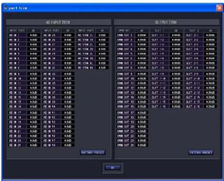
PM5D Editor does not have a corresponding window.
Here you can make fine adjustments to the AD input/output gain.
As necessary, make fine adjustments to the gain of the specified analog input/output port. You can adjust this in 0.1 dB units for input ports, and in 0.01 dB units for output ports. When the unit is shipped from the factory, the input levels of each port are set to match, so there is normally no need to adjust this.
If you need to make fine adjustments to the gain, hold down the left mouse button on the dB area of the desired port, and move the cursor up/down; alternatively, you can double-click the dB area and enter a value. If you want to return all input ports to their factory-set state, click the FACTORY PRESET button. When you click the OK button, the Port Trim window will close.
Keyboard Shortcuts
| Menu Action Windows | Windows Mac | ||
| File menu | Creates a new Session Ctrl+N | ⌘ +N | |
| Opens a previously saved Session Ctrl+O | ⌘ +O | ||
| Saves the current Session Ctrl+S | ⌘ +S | ||
| Edit menu | Undo Ctrl+Z | ⌘ +Z | |
| Redo Ctrl+Y | ⌘ +Y | ||
| Ch Copy Ctrl+C | ⌘ +C | ||
| Ch Paste Ctrl+V | ⌘ +V | ||
| Windows menu | Closes the active window Ctrl+W | ⌘ +W | |
| Closes all windows Ctrl+Alt+W | ⌘ +Option+W | ||
| Opens the Sync window Ctrl+1 | ⌘ +1 | ||
| Opens the INPUT CH (CH1-24) window Ctrl+2 | ⌘ +2 | ||
| Opens the INPUT CH (CH25-48) window | Ctrl+Alt+2 | ⌘ +Option+2 | |
| Opens the Selected Channel window | Ctrl+3 | ⌘ +3 | |
| Opens the Library window Ctrl+4 | ⌘ +4 | ||
| Opens the Patch Editor window | Ctrl+5 | ⌘ +5 | |
| Opens the Surround Editor window | Ctrl+6 | ⌘ +6 | |
| Opens the Timecode Counter window(*) | Ctrl+7 | ⌘ +7 | |
| Opens the Effect Editor window | Ctrl+8 | ⌘ +8 | |
| Opens the Meter window | Ctrl+9 | ⌘ +9 | |
| Opens the GEQ Editor window | Ctrl+0 | ⌘ +0 | |
| Opens the DCA/Mute Group window | Ctrl+Alt+1 | ⌘ +Option+1 | |
| Opens the Scene window | Ctrl+Alt+3 | ⌘ +Option+3 | |
| Library window or SCENE MEMORY page of the Scene window | Selects consecutive multiple items (memories) | Shift+click | shift+click |
| Selects non-consecutive multiple items (memories) | Ctrl+click | ⌘ +click | |
| Selects all memories in a section | Ctrl+A | ⌘ +A |
(*) PM5D Editor only.
Index
Symbols
+48V Master 4
A
ALL INPUT CHANNEL ...... 64
B
Bus Setup 3
BYPASS 53
C
Cascade Connection 4
CH to MIX 30
Channel to mix 30
CLEAR 61,68
CLEAR ALL 65
CLOSE 57,66
COMMENT 58
Console Device ID 2
CSV file
Export 44
Import 44
Ctrl ( ℹ+ click ...... 7
Ctrl ( Shift+Click 7
Cue/Solo window 79,82
D
DCA fader 21
DCA group 54
DCA GROUP ASSIGN page ..... 54
DCA window 21
DCA/MUTE GROUP window DCA GROUP ASSIGN page ... 54
MUTE GROUP ASSIGN page 55
DCA/Mute Group window ..... 54
DELAY TIME 59
DIRECT OUTPUT PATCH page .42
DIVERGENCE 46
DME Connection 4
E
Edit 6
Effect
Equalizer 52
GR meter 52
SOLO 52
Effect Editor window 50
Effect parameters 51
EFFECT TYPE 50
EQ FLAT 48
EVENT LIST page 62
EVENT TRIGGER 62
EXPORT 44
External HA 4
F
Fade 64
Fade function enable/disable ...... 64
FADE TIME page 64
Fader Mode Assign window ..... 73
FADING ENABLE 64
Fast Sync 2,3
FILE 58,66
File
Close 57,66
Open 57,66
FX RTN window 13
G
GEQ faders 48
GEQ graph 48
GEQ window 47
GPI OUT CONTROL 59
|
IMPORT 44
INPUT CH window 8
INPUT CHANNEL PANNING ENABLE 64
Input channel panning enable/ disable 64
INPUT INSERT PATCH page ..... 41
INPUT PATCH page 40
Input port/Output port ......2, 3
INTERNAL DATA ....60, 67
IP Address 4
K
Keyboard Shortcuts 83
L
Level Meter 2,3
LFE 46
Library link 58
Library window 66
LIMIT 48
LINK PATTERN SELECT ...... 45
Low Frequency Effect 46
M
MATRIX window 17
Meter window 68
MIDI EVENT 59
MIDI event transmission ..... 59
MIX BALANCE 53
MIX to MATRIX ....35
MIX window 15
MODULE 47
Module number ......67
Mute group ....56
MUTE GROUP ASSIGN page .....55
MUTE MASTER ....56
MUTE SAFE ON/OFF .....56
N
Number of Effects ....4
0
Offline Edit ....5
OPEN 57,66
Oscillator window .....77
OUTPUT EQ 67
OUTPUT INSERT PATCH page ..42
OUTPUT PATCH page ....41
Output Port Att window .....73
Output Port Attenuator window ...73
P
Pair Mode ....3
Pan Nominal Position ....3
PAN POSITION ....46
Patch Editor window 40
DIRECT OUTPUT PATCH page ....42
INPUT INSERT PATCH page .41
INPUT PATCH page ....40
OUTPUT INSERT PATCH page 42
OUTPUT PATCH page ......41
PATCH LIST page ....43
PATCH LIST page 43
PEQ 67
PLAY/REC 53
Port Trim window 82
Preference window 70
PROTECT 58,61
R
READ Only 67
RECALL 61,67
Recall Safe 63
RECALL SAFE page ......63
REDO 7
REMOTE TRANSPORT .....59
Re-synchronize ....5
S
SAME AS FADING 64
SAVE 57,66
SAVE AS 57,66
Save as a different name ..... 57
Save under a different name .... 66
SCENE MEMORY page 57
Scene window 57
EVENT LIST page 62
FADE TIME page 64
RECALL SAFE page 63
SCENE MEMORY page ...... 57
SELECTIVE RECALL page ..... 63
SEL 58
SEL. RECALL 58
Selected Channel window ...... 22
Channel selection 22
Channel to mix 30
COMPRESSOR 25
DCA GROUP / MUTE GROUP / SAFE ....28, 33
DELAY 28
EQUALIZER 27,32
GATE 23
HA gain/phase/high-pass filter 23
Input channel 22
INSERT 26
M/S DECODE 28
MATRIX channel 36
MIX channel 31
MIX to MATRIX 35
Pan / Fader ...... 29, 34, 37, 38
STEREO A/B channel 37
STEREO to MATRIX 39
Selective recall 58
SELECTIVE RECALL page ...... 63
Sessions 5
SET ALL 65
Set Default 2,3
Setup
Mixer 3
ST IN window 11
Stereo B Setup 3
STEREO to MATRIX 39
STEREO window 19
STORE 61,67
Surround Bus Allocation 3
Surround Editor window 45
Surround Mode 4,45
Sync window 69
Synchronize 5
Synchronize Plug-in Boards ...... 2
System Color 2,3
T
Tabs 6
TEMPO 53
TIME STAMP 58
Timecode Counter window ...... 69
TX 59
U
UNDO 7,61,68
User Defined Keys Setup window 72
W
Window Control from Console ..... 2
Word Clock window 74
Y
Yamaha Pro Audio Global Site ..... 1
- Yamaha Pro Audio Global Site
- Contents
- Description of menus and buttons
- Getting Started
- What is PM5D/DSP5D Editor?
- Settings in PM5D/DSP5D Editor
- NOTE
- PM5D Editor: System Setup
- □DSP5D Editor: System Setup
- Mixer Setup
- - Input Port / Output Port
- - Monitor Port
- - Connect
- • MIDI Program Change
- Synchronizing PM5D/DSP5D Editor
- Select [Synchronize], then [Re-synchronize].
- Select whether you want to transfer your settings to PM5D/DSP5D Editor, or vice versa.
- Click [OK].
- Offline Edit Function
- Working with Sessions
- Window operations
- Edit functions
- ☐ Ch Copy / Ch Paste (channel copy / channel paste) function
- ☐ Ch Move (channel move) function
- Other Functions
- ☐ Resetting to the default value (Ctrl (⌘ + click)
- Ctrl (⌘ +Shift+Click
- INPUT CH window
- ① Input patch
- ② +48V
- ③ HA GAIN
- ⑰ Channel name
- ⑱ Fader
- ⑲ CUE
- ST IN window
- FX RTN window
- ① EQ (Equalizer)
- ② COMP (Compressor)
- ③ INSERT
- ④ DELAY
- ⑤ Channel number
- ⑥ MTRX (Send level to MATRIX buses)
- ⑦ TO ST (To STEREO)
- ⑧ PAN
- ⑨ VARI/FIXED
- ⑩ SELECT
- ⑪ ON
- ⑫ Channel name
- ⑬ Fader
- ⑭ CUE
- MATRIX window
- STEREO window
- ⑦ BALANCE
- ⑧ SELECT
- ⑨ ON
- ⑩ Channel name
- ⑪ Fader
- ⑫ CUE
- Selected Channel window
- If an input channel is selected
- ☐ CHANNEL SELECT (Channel selection)
- ☐ HA GAIN/∅/HPF (HA gain/phase/high-pass filter)
- ① HA GAIN
- ② ∅ (Phase)
- ③ HPF (High Pass Filter)
- ☐ GATE (except for FX RTN channels)
- ① Gate graph
- ② GR meter
- ③ TYPE
- ④ THRESHOLD (Threshold level)
- ⑤ RANGE
- COMPRESSOR (except for FX RTN channels)
- ☐ INSERT (except for FX RTN channels)
- ☐ DELAY (except for FX RTN channels)
- ☐ M/S DECODE (except for FX RTN channels)
- DCA GROUP / MUTE GROUP / SAFE
- Pan / Fader
- ☐ CH to MIX (Channel to mix)
- ① MIX send level
- ② Pair
- ③ ON (MIX send on/off)
- ④ PRE (Pre/Post)
- ⑤ CH to MIX PRE POINT
- COMPRESSOR
- INSERT
- ⑬ EQ LINK GROUP
- ⑭ UPPER/LOWER
- DELAY
- ☐ DCA GROUP / MUTE GROUP / SAFE
- ① DCA GROUP
- ② MUTE GROUP
- ③ RECALL SAFE / MUTE SAFE
- ① TO ST (To stereo)
- ② TO ST PAN (To stereo pan)
- ③ LCR
- ④ CSR (Center Side Ratio)
- ⑤ BALANCE
- ⑥ ON
- ⑦ Fader
- ⑧ CUE
- EQUALIZER
- ① BALANCE
- ② ON
- ③ Fader
- ④ CUE
- If a STEREO A/B channel is selected
- □ DELAY
- STEREO to MATRIX
- Patch Editor window
- INPUT PATCH page
- INPUT INSERT PATCH page
- DIRECT OUTPUT PATCH page
- ① Input channel number Input channel name
- ② Input port
- ③ Output channel number Output channel name
- ④ Output port
- ⑤ IMPORT (Import a CSV file)
- ⑥ EXPORT (Export a CSV file)
- Surround Editor window
- ⑥ DIVERGENCE
- - Surround mode= 3-1ch/5.1ch
- • Surround mode= 6.1ch
- ⑦ LFE (Low Frequency Effect)
- ⑧ SURROUND BUS ON (Surround bus on/off)
- ⑨ PANNING buttons
- ⑩ Grid
- ⑪ PAN POSITION
- GEQ window
- ⑦ GEQ graph
- ⑧ GEQ faders
- ⑨ LIMIT
- ⑩ EQ FLAT
- Effect Editor window
- ⑤Effect parameters
- ⑥ Input meter
- ⑦ Input patch
- ⑧ Output meter
- ⑨ Output patch
- ⑩ GR meter
- ⑪ SOLO
- ⑫ Equalizer
- DCA/Mute Group window
- DCA GROUP ASSIGN page
- ③ Grid
- ④ CLEAR
- MUTE GROUP ASSIGN page
- Scene window
- SCENE MEMORY page
- ⑥ FILE
- ⑦ No. (Scene number)
- ⑧ TITLE
- ⑨ PROTECT
- ⑩ SEL. RECALL (Selective recall)
- ⑪ Library link
- ⑫ COMMENT
- ⑬ TIME STAMP
- ⑭ MIDI EVENT
- ⑮ TX (MIDI event transmission)
- ⑯ DELAY TIME
- - POST
- - INTERVAL
- ⑰ GPI OUT CONTROL
- ⑱ REMOTE TRANSPORT
- ⑲ INTERNAL DATA
- • T o select a single scene
- • T o select multiple consecutive scenes
- • T o select multiple non-consecutive scenes
- • T o copy scenes (overwriting the destination)
- • T o move scenes
- ⑳ STORE
- ②1 RECALL
- CLEAR
- UNDO
- ⑳ PROTECT
- ① No. (Number)
- ② EVENT TRIGGER
- ③ SCENE TITLE
- RECALL SAFE page
- ③ SET ALL
- ④ CLEAR ALL
- ⑤ Channel settings
- Library window
- CLEAR
- UNDO
- Meter window
- Timecode Counter window
- Sync window
- Preference window
- ① STORE/RECALL
- • LINKED LIBRARY PROTECTION
- - STORE CONFIRMATION
- - RECALL CONFIRMATION
- ② PATCH
- - PATCH CONFIRMATION
- • STEAL PATCH CONFIRMATION
- ③ GATE/COMP (gate / compressor)
- • GR METER ON/OFF LINK
- ④ DCA MUTE TARGET
- ⑤ WARNING DISPLAY
- • TIME CODE DROP
- • DIGITAL I/O ERROR
- - MIDI I/O ERROR
- ⑥ SOFTWARE VERSION
- ⑦ BATTERY
- User Defined Keys Setup window
- Fader Mode Assign window
- Output Port Att window
- Word Clock window
- ① MASTER CLOCK SELECT
- - LOCK ( )
- - UNLOCK ( )
- - LOCK, but NOT SYNC'ED ( )
- - UNKNOWN ( )
- - SRC ON ( )
- ② Fs (sampling frequency)
- ③ SLOT SETUP
- - SLOT number and card type
- - INPUT FORMAT (input signal format) / OUTPUT FORMAT (output signal format)
- SINGLE
- DOUBLE SPEED
- DOUBLE CHANNEL
- • FREQUENCY (sampling rate)
- - SRC (sampling rate converter)
- • EMPHASIS STATUS
- • DITHER
- Oscillator window
- - HPF (high pass filter) / LPF (low pass filter)
- - WIDTH/INTERVAL
- - OSC OUT (oscillator direct output)
- - BUS ASSIGN
- Cue/Solo window
- ① SOLO ON/OFF
- • CUE mode (SOLO ON/OFF button is off)
- • SOLO mode (SOLO ON/OFF button is on)
- ② CUE MODE
- - MIX CUE mode
- - LAST CUE mode
- ③ CUE FUNCTION
- • MIX CUE LINK
- - CUE/SEL LINK
- • F ADER/CUE RELEASE
- ④ INPUT
- ⑤ DCA
- • DCA TRIM
- • DCA UNITY
- HINT
- - PRE PAN/POST PAN
- ⑥ OUTPUT
- ⑦ INPUT SOLO SAFE
- ⑧ OUTPUT SOLO SAFE
- ⑨ Level meter
- ⑩ MONITOR/CUE DELAY
- ⑪ CUE LEVEL
- ⑫ CUE OUT
- Port Trim window
- Keyboard Shortcuts
- Index
- Symbols
- A
- B
- C
- D
- E
- F
- G
- |
- K
- L
- M
- N
- 0
- P
- R
- S
- T
- U
- W
- Y
Brand : YAMAHA
Model : DCU5D
Category : Blender