
MG124 - Blender YAMAHA - Free user manual and instructions
Find the device manual for free MG124 YAMAHA in PDF.


| Product Type | Mixing Console |
| Brand | Yamaha |
| Model | MG124 (MG124CX with effects, MG124C without) |
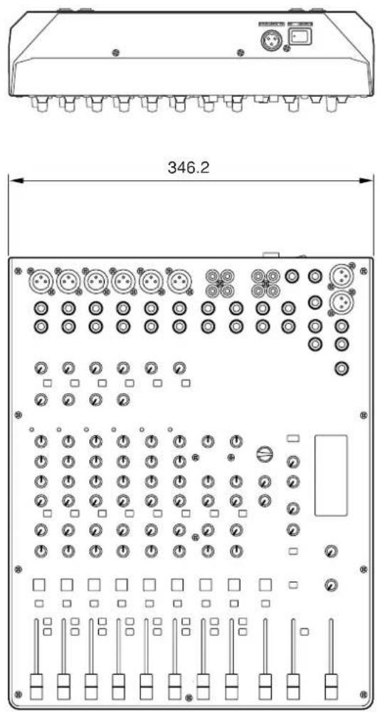
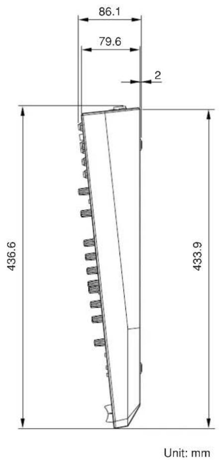
| Dimensions (W x H x D) | 346.2 mm x 86.1 mm x 436.6 mm |
| Net Weight | 3.2 kg (MG124CX), 3.0 kg (MG124C) |
| Power Supply | AC adaptor PA-20; AC 35 VCT, 0.94 A; 30 W |
| Input Channels | 4 mono mic/line (XLR & TRS), 2 stereo mic/line (XLR & phone), 2 stereo line (phone & RCA) |
| Outputs | STEREO OUT (XLR & TRS), GROUP OUT (1-2), MONITOR OUT, REC OUT, PHONES, AUX SEND, EFFECT SEND |
| Equalization | Mono: 3-band (HIGH 10 kHz, MID 2.5 kHz, LOW 100 Hz); Stereo: 2-band (HIGH 10 kHz, LOW 100 Hz); ±15 dB cut/boost |
| Built-in Effects (MG124CX only) | 16 digital effects (reverb, chorus, flanger, phaser, etc.) with parameter control and foot switch |
| Phantom Power | +48 V switchable to all XLR mic inputs |
| Compressor | Single-knob compressor on mono channels |
| High Pass Filter | 80 Hz, 12 dB/octave on channels 1-7/8 |
| Frequency Response | 20 Hz - 20 kHz, +0.5/-1.5 dB (STEREO OUT) |
| Total Harmonic Distortion | 0.1% (STEREO OUT, +14 dBu) |
| Maintenance and Cleaning | Disconnect power; wipe with a dry, soft cloth. Do not use solvents. |
| Safety Precautions | Use only specified voltage and adaptor; avoid water, excess dust, and extreme temperatures; do not open; ensure proper ventilation. |
| Spare Parts and Repairability | Contact qualified Yamaha service personnel for repairs; no user-serviceable parts inside. |
| General Information | Owner's manual included; AC adaptor PA-20 included (may vary by region) |
Frequently Asked Questions - MG124 YAMAHA
User questions about MG124 YAMAHA
0 question about this device. Answer the ones you know or ask your own.
Ask a new question about this device
Download the instructions for your Blender in PDF format for free! Find your manual MG124 - YAMAHA and take your electronic device back in hand. On this page are published all the documents necessary for the use of your device. MG124 by YAMAHA.
USER MANUAL MG124 YAMAHA
Input Channels......page 12 With up to six mic/line inputs or up to four stereo inputs, the MG mixer can simultaneously connect to a wide range of devices: microphones, line-level devices, stereo synthesizers, and more.
Compression......page 10 Compression increases the overall level without introducing distortion by compressing excessive peaks in the signals from microphones and guitars.
AUX Sends and Stereo AUX Return......page 14 You can use the AUX SEND jack to feed the signal sent to an external signal processor, and then return the processed stereo signal through the RETURN jack.
High-quality digital effects (MG124CX)......page 16, 17 With digital effects built in, the MG124CX can deliver a wide range of sound variations all by itself.
Funktionen
Connecting the Plug and Cord
IMPORTANT. The wires in this mains lead are coloured in accordance with the following code:
BLUE : NEUTRAL
BROWN : LIVE
As the colours of the wires in the mains lead of this apparatus may not correspond with the coloured makings identifying the terminals in your plug proceed as follows:
The wire which is coloured BLUE must be connected to the terminal which is marked with the letter N or coloured BLACK.
The wire which is coloured BROWN must be connected to the terminal which is marked with the letter L or coloured RED.
Making sure that neither core is connected to the earth terminal of the three pin plug.
- This applies only to products distributed by Yamaha-Kemble Music (U.K.) Ltd. (2 wires)
FCC INFORMATION (U.S.A.)
1. IMPORTANT NOTICE: DO NOT MODIFY THIS UNIT!
This product, when installed as indicated in the instructions contained in this manual, meets FCC requirements. Modifications not expressly approved by Yamaha may void your authority, granted by the FCC, to use the product.
- IMPORTANT: When connecting this product to accessories and/or another product use only high quality shielded cables. Cable/s supplied with this product MUST be used. Follow all installation instructions. Failure to follow instructions could void your FCC authorization to use this product in the USA.
- NOTE: This product has been tested and found to comply with the requirements listed in FCC Regulations, Part 15 for Class "B" digital devices. Compliance with these requirements provides a reasonable level of assurance that your use of this product in a residential environment will not result in harmful interference with other electronic devices. This equipment generates/uses radio frequencies and, if not installed and used according to the instructions found in the users manual, may cause interference harmful to the operation of other electronic devices. Compliance with FCC
regulations does not guarantee that interference will not occur in all installations. If this product is found to be the source of interference, which can be determined by turning the unit "OFF" and "ON", please try to eliminate the problem by using one of the following measures:
Relocate either this product or the device that is being affected by the interference.
Utilize power outlets that are on different branch (circuit breaker or fuse) circuits or install AC line filter/s.
In the case of radio or TV interference, relocate/reorient the antenna. If the antenna lead-in is 300 ohm ribbon lead, change the lead-in to co-axial type cable.
If these corrective measures do not produce satisfactory results, please contact the local retailer authorized to distribute this type of product. If you can not locate the appropriate retailer, please contact Yamaha Corporation of America, Electronic Service Division, 6600 Orangethorpe Ave, Buena Park, CA90620
The above statements apply ONLY to those products distributed by Yamaha Corporation of America or its subsidiaries.
PRECAUTIONS
PLEASE READ CAREFULLY BEFORE PROCEEDING
* Please keep this manual in a safe place for future reference.

WARNING
Always follow the basic precautions listed below to avoid the possibility of serious injury or even death from electrical shock, short-circuiting, damages, fire or other hazards. These precautions include, but are not limited to, the following:
Power supply/Power cord
- Only use the voltage specified as correct for the device. The required voltage is printed on the name plate of the device.
- Use only the specified AC power adaptor (PA-20) or an equivalent recommended by Yamaha).
If you intend to use the device in an area other than in the one you purchased, the included power cord may not be compatible. Please check with your Yamaha dealer. - Do not place the power cord near heat sources such as heaters or radiators, and do not excessively bend or otherwise damage the cord, place heavy objects on it, or place it in a position where anyone could walk on, trip over, or roll anything over it.
Do not open
- Do not open the device or attempt to disassemble the internal parts or modify them in any way. The device contains no user-serviceable parts. If it should appear to be malfunctioning, discontinue use immediately and have it inspected by qualified Yamaha service personnel.
Water warning
- Do not expose the device to rain, use it near water or in damp or wet conditions, or place containers on it containing liquids which might spill into any openings.
- Never insert or remove an electric plug with wet hands.
If you notice any abnormality
- If the power cord or plug becomes frayed or damaged, or if there is a sudden loss of sound during use of the device, or if any unusual smells or smoke should appear to be caused by it, immediately turn off the power switch, disconnect the electric plug from the outlet, and have the device inspected by qualified Yamaha service personnel.
- If this device or the AC power adaptor should be dropped or damaged, immediately turn off the power switch, disconnect the electric plug from the outlet, and have the device inspected by qualified Yamaha service personnel.

CAUTION
Always follow the basic precautions listed below to avoid the possibility of physical injury to you or others, or damage to the device or other property. These precautions include, but are not limited to, the following:
Power supply/Power cord
- Remove the electric plug from the outlet when the device is not to be used for extended periods of time, or during electrical storms.
- When removing the electric plug from the device or an outlet, always hold the plug itself and not the cord. Pulling by the cord can damage it.
- T o avoid generating unwanted noise, make sure there is 50cm or more between the AC power adaptor and the device.
- Do not cover or wrap the AC power adaptor with a cloth or blanket.
Location
- Before moving the device, remove all connected cables.
- When setting up the device, make sure that the AC outlet you are using is easily accessible. If some trouble or malfunction occurs, immediately turn off the power switch and disconnect the plug from the outlet.
- A void setting all equalizer controls and faders to their maximum. Depending on the condition of the connected devices, doing so may cause feedback and may damage the speakers.
- Do not expose the device to excessive dust or vibrations, or extreme cold or heat (such as in direct sunlight, near a heater, or in a car during the day) to prevent the possibility of panel disfiguration or damage to the internal components.
- Do not place the device in an unstable position where it might accidentally fall over.
- Do not use the device in the vicinity of a TV, radio, stereo equipment, mobile phone, or other electric devices. Doing so may result in noise, both in the device itself and in the TV or radio next to it.
Connections
- Before connecting the device to other devices, turn off the power for all devices. Before turning the power on or off for all devices, set all volume levels to minimum.
Handling caution
- When turning on the AC power in your audio system, always turn on the power amplifier LAST, to avoid speaker damage. When turning the power off, the power amplifier should be turned off FIRST for the same reason.
- Do not insert your fingers or hands in any gaps or openings on the device.
- A void inserting or dropping foreign objects (paper, plastic, metal, etc.) into any gaps or openings on the device. If this happens, turn off the power immediately and unplug the power cord from the AC outlet. Then have the device inspected by qualified Yamaha service personnel.
- Do not use the device or headphones for a long period of time at a high or uncomfortable volume level, since this can cause permanent hearing loss. If you experience any hearing loss or ringing in the ears, consult a physician.
- Do not rest your weight on the device or place heavy objects on it, and avoid use excessive force on the buttons, switches or connectors.
XLR-type connectors are wired as follows (IEC60268 standard): pin 1: ground, pin 2: hot (+), and pin 3: cold (-).
Insert TRS phone jacks are wired as follows: sleeve: ground, tip: send, and ring: return.
Yamaha cannot be held responsible for damage caused by improper use or modifications to the device, or data that is lost or destroyed.
Always turn the power off when the device is not in use.
Even when the power switch is in the "STANDBY" position, electricity is still flowing to the device at the minimum level. When you are not using the device for a long time, make sure you unplug the power cord from the wall AC outlet.
The performance of components with moving contacts, such as switches, volume controls, and connectors, deteriorates over time. Consult qualified Yamaha service personnel about replacing defective components.
The MG mixer may heat up by as much as 15 to 20^ while the power is on. This is normal. Please note that the panel temperature may exceed 50^ in ambient temperatures higher than 30^ , and use caution to prevent burns.
* This Owner's Manual applies to both the MG124CX and MG124C. The main difference between the two models is that the MG124CX includes digital effects while the MG124C has no internal effects.
* In this manual the term "MG mixers" refers to both the MG124CX and MG124C. In cases where different features need to be described for each model, the MG124CX feature will be described first, followed by the MG124C feature in brackets: MG124CX (MG124C).
* Illustrations herein are for explanatory purposes only, and may not match actual appearance during operation.
* Company names and product names herein are trademarks or registered trademarks of their respective companies.
Copying of commercially available music or other audio data for purposes other than personal use is strictly prohibited by copyright law. Please respect all copyrights, and consult with a copyright specialist if you are in doubt about permissible use.
Specifications and descriptions in this owner's manual are for information purposes only. Yamaha Corp. reserves the right to change or modify products or specifications at any time without prior notice. Since specifications, equipment or options may not be the same in every locale, please check with your Yamaha dealer.
Introduction
Thank you for your purchase of the YAMAHA MG124CX/MG124C mixing console. The MG124CX/MG124C feature input channels suitable for a wide range of usage environments. And the MG124CX includes high-quality built-in digital effects that can provide some very serious sound. The mixer combines ease of operation with support for multiple usage environments.
Please read through this manual carefully before beginning use, so that you will be able to take full advantage of this mixer's superlative features and enjoy trouble-free operation for years to come.
Contents
Introduction 5
Contents 5
Before Turning on the Mixer 5
Turning the Power On.... 5
Mixer Basics
Quick Guide...... 6
Making the Most of Your Mixer...... 8
Balanced, Unbalanced—What's the Difference?.... 8
Signal Levels and the Decibel 8
To EQ or Not to EQ 9
Ambience....10
The Modulation Effects: 10
Phasing, Chorus, and Flanging 10
Compression.... 10
■ Reference
Setup 11
Front & Rear Panels.... 12
Channel Control Section....12
Master Control Section 14
DIGITAL EFFECT....16
Rear Input/Output Section 16
Digital Effect Program List 17
Jack List....17
Troubleshooting.... 18
Specifications...... 67
Accessories
□ Owner's Manual
□ AC power adaptor (PA-20)*
* May not be included depending on your particular area. Please check with your Yamaha dealer.
Before Turning on the Mixer
1 Be sure that the mixer's power switch is in the STANDBY position.

Use only the PA-20 adaptor included with this mixer. Use of a different adaptor may result in equipment damage, overheating, or fire.
2 Connect the power adaptor to the AC ADAPTOR IN connector (①) on the rear of the mixer, and then turn the fastening ring clockwise (②) to secure the connection.
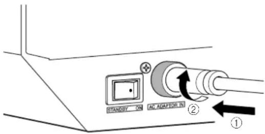
3 Plug the power adaptor into a standard household power outlet.

- Be sure to unplug the adaptor from the outlet when not using the mixer, or when there are lightning storms in the area.
- To avoid generating unwanted noise, make sure there is 50 cm or more between the power adaptor and the mixer.
Turning the Power On
Press the mixer's power switch to the ON position. When you are ready to turn the power off, press the power switch to the STANDBY position.

Note that trace current continues to flow while the switch is in the STANDBY position. If you do not plan to use the mixer again for a long while, please be sure to unplug the adaptor from the wall outlet.
Getting Sound to the Speakers
We begin by connecting a pair of speakers and generating some stereo output. Note that operations and procedures will vary somewhat according to the input devices you are using.
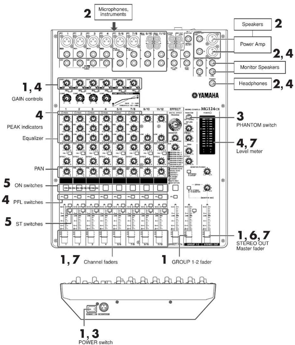
1 Be sure that your mixer is turned off and that all level* controls are turned all the way down.
* STEREO OUT Master Fader, Channel Fader, GROUP 1-2 Fader, Gain Control, etc.
NOTE
Set the equalizer and the pan controls to their ▼ positions.
2 Turn off any other external devices, then connect microphones, instruments, and speakers.
NOTE
* F or information on connecting external devices see the Connection Example on page 11.
* Connect electric guitars and basses through an intermediary device such as a direct box, preamp, or amp simulator. Connecting these instruments directly to the MG mixer may result in degraded sound and noise.
3 To avoid damage to your speakers, power up the devices in the following order: Peripheral devices → MG mixer → power amps (or powered speakers). Reverse this order when turning power off.
NOTE
If you are using microphones that require phantom power, turn the MG mixer's phantom power switch on before turning on the power to the power amp or powered speakers. See page 15 for more detail.
4 Adjust the channel GAIN controls so that the corresponding peak indicators flash briefly on the highest peak levels.
NOTE
To use the LEVEL meter to get an accurate reading of the incoming signal level, turn the channel PFL switch on. Adjust the GAIN controls so that the LEVEL meter indication occasionally rises above the “▼” (0) level. Note that the PHONES jack outputs the pre-fader signal from all channels on which the PFL switch is ON so that those signals can be monitored via the headphones.
5 Turn on the ON and ST switches for each channel you are using.
6 Set the STEREO OUT Master fader to the "0" position.
7 Set the Channel faders to create the desired initial balance, then adjust the overall volume using the STEREO OUT Master fader.
NOTE
* To use the LEVEL meter to view the level being applied to the STEREO L/R buses, set the PFL switch off ( ) and the MONITOR switch to STE-REO ( ).
* If the PEAK indicator lights frequently, lower the Channel faders a little to avoid distortion.
You've got yourself a mixer and now you're ready to use it.
Just plug everything in, twiddle the controls, and away you go ... right?
Well, if you've done this before you won't have any problems, but if this is the first time you've ever used a mixer you might want to read through this little tutorial and pick up a few basics that will help you get better performance and make better mixes.
Balanced, Unbalanced—What's the Difference?
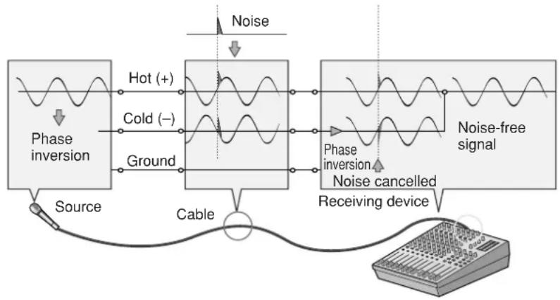
In a word: “noise.” The whole point of balanced lines is noise rejection, and it’s something they’re very good at. Any length of wire will act as an antenna to pick up the random electromagnetic radiation we’re constantly surrounded by: radio and TV signals as well as spurious electromagnetic noise generated by power lines, motors, electric appliances, computer monitors, and a variety of other sources. The longer the wire, the more noise it is likely to pick up. That’s why balanced lines are the best choice for long cable runs. If your “studio” is basically confined to your desktop and all connections are no more than a meter or two in length, then unbalanced lines are fine—unless you’re surrounded by extremely high levels of electromagnetic noise. Another place balanced lines are almost always used is in microphone cables. The reason for this is that the output signal from most microphones is very small, so even a tiny amount of noise will be relatively large, and will be amplified to an alarming degree in the mixer’s high-gain head amplifier.
Balanced noise cancellation
flowchart
graph LR
    A["Source"] --> B["Phase inversion"]
    B --> C["Hot (+)"]
    B --> D["Cold (−)"]
    B --> E["Ground"]
    C --> F["Phase inversion"]
    D --> F
    E --> F
    F --> G["Receiving device"]
    G --> H["Noise-free signal"]
    H --> I["Noise"]
    I --> J["Noise"]
    J --> K["Noise"]
    K --> L["Noise"]
    L --> M["Noise"]
To summarize
| Microphones: Use | balanced lines. |
| Short line-level runs: | Unbalanced lines are fine if you're in a relatively noise-free environment. |
| Long line-level runs: | The ambient electromagnetic noise level will be the ultimate deciding factor, but balanced is best. |
Signal Levels and the Decibel
Let's take a look at one of the most commonly used units in audio: the decibel (dB). If the smallest sound that can be heard by the human ear is given an arbitrary value of 1, then the loudest sound that can be heard is approximately 1,000,000 (one million) times louder. That's too many digits to deal with for practical calculations, and so the more appropriate "decibel" (dB) unit was created for sound-related measurements. In this system the difference between the softest and loudest sounds that can be heard is 120 dB. This is a non-linear scale, and a difference of 3 dB actually results in a doubling or halving of the loudness.
You might encounter a number of different varieties of the dB: dBu, dBV, dBM and others, but the dBu is the basic decibel unit. In the case of dBu, "0 dBu" is specified as a signal level of 0.775 volts. For example, if a microphone's output level is -40 dBu (0.00775 V), then to raise that level to 0 dBu (0.775 V) in the mixer's preamp stage requires that the signal be amplified by 100 times.
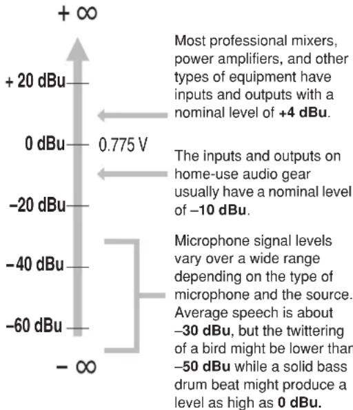
other
| Category | Value | | -------- | ----- | | Most professional mixers, power amplifiers, and other types of equipment have inputs and outputs with a nominal level of +4 dBu. | 0.775 V | | The inputs and outputs on home-use audio gear usually have a nominal level of -10 dBu. | -10 dBu | | Microphone signal levels vary over a wide range depending on the type of microphone and the source. Average speech is about -30 dBu, but the twittering of a bird might be lower than -50 dBu while a solid bass drum beat might produce a level as high as 0 dBu. | -60 dBu |A mixer may be required to handle signals at a wide range of levels, and it is necessary match input and output levels as closely as possible. In most cases the “nominal” level for a mixer’s input and outputs is marked on the panel or listed in the owner’s manual.
To EQ or Not to EQ
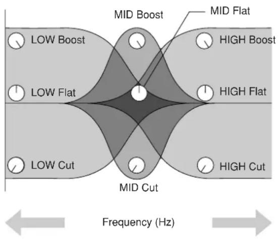
In general: less is better. There are many situations in which you'll need to cut certain frequency ranges, but use boost sparingly, and with caution. Proper use of EQ can eliminate interference between instruments in a mix and give the overall sound better definition. Bad EQ—and most commonly bad boost—just sounds terrible.
Cut for a Cleaner Mix
For example: cymbals have a lot of energy in the mid and low frequency ranges that you don't really perceive as musical sound, but which can interfere with the clarity of other instruments in these ranges. You can basically turn the low EQ on cymbal channels all the way down without changing the way they sound in the mix. You'll hear the difference, however, in the way the mix sounds more "spacious," and instruments in the lower ranges will have better definition. Surprisingly enough, piano also has an incredibly powerful low end that can benefit from a bit of low-frequency roll-off to let other instruments—notably drums and bass—do their jobs more effectively. Naturally you won't want to do this if the piano is playing solo.
The reverse applies to kick drums and bass guitars: you can often roll off the high end to create more space in the mix without compromising the character of the instruments. You'll have to use your ears, though, because each instrument is different and sometimes you'll want the "snap" of a bass guitar, for example, to come through.
The fundamental and harmonic frequency ranges of some musical instruments.
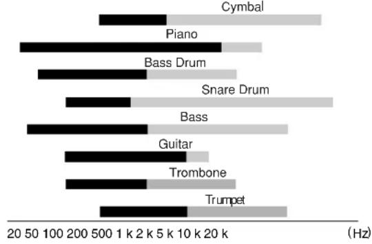
bar
| Instrument | Frequency (Hz) | | :--- | :--- | | Cymbal | 1000 | | Piano | 2000 | | Bass Drum | 3000 | | Snare Drum | 4000 | | Bass | 1000 | | Guitar | 2000 | | Trombone | 1500 | | Trumpet | 1500 |■ Fundamental: The frequency that determines the basic musical pitch.
Harmonics: Multiples of the fundamental frequency that play a role in determining the timbre of the instrument.
Some Frequency Facts
The lowest and highest frequencies than can be heard by the human ear are generally considered to be around 20 Hz and 20,000 Hz, respectively. Average conversation occurs in the range from about 300 Hz to about 3,000 Hz. The frequency of a standard pitchfork used to tune guitars and other instruments is 440 Hz (this corresponds to the "A3" key on a piano tuned to concert pitch). Double this frequency to 880 Hz and you have a pitch one octave higher (i.e. "A4" on the piano keyboard). In the same way you can halve the frequency to 220 Hz to produce "A2" an octave lower.
Boost with Caution
If you're trying to create special or unusual effects, go ahead and boost away as much as you like. But if you're just trying to achieve a good-sounding mix, boost only in very small increments. A tiny boost in the midrange can give vocals more presence, or a touch of high boost can give certain instruments more "air." Listen, and if things don't sound clear and clean try using cut to remove frequencies that are cluttering up the mix rather than trying to boost the mix into clarity.
One of the biggest problems with too much boost is that it adds gain to the signal, increasing noise and potentially overloading the subsequent circuitry.

Ambience
Your mixes can be further refined by adding ambience effects such as reverb or delay. The MG's internal effects can be used to add reverb or delay to individual channels in the same way as external effects processors. (Refer to page 16).
Reverb and Delay Time
The optimum reverb time for a piece of music will depend on the music's tempo and density, but as a general rule longer reverb times are good for ballads, while shorter reverb times are more suited to up-tempo tunes. Delay times can be adjusted to create a wide variety of "grooves". When adding delay to a vocal, for example, try setting the delay time to dotted eighth notes corresponding to the tune's tempo.
Reverb Tone
Different reverb programs will have different “reverb tone” due to differences in the reverb time of the high or low frequencies. Too much reverb, particularly in the high frequencies, can result in unnatural sound and interfere with the high frequencies in other parts of the mix. It’s always a good idea to choose a reverb program that gives you the depth you want without detracting from the clarity of the mix.
Reverb Level
It's amazing how quickly your ears can lose perspective and fool you into believing that a totally washed-out mix sounds perfectly fine. To avoid falling into this trap start with reverb level all the way down, then gradually bring the reverb into the mix until you can just hear the difference. Any more than this normally becomes a “special effect.”
The Modulation Effects:
Phasing, Chorus, and Flanging
All of these effects work on basically the same principle: a portion of the audio signal is “time-shifted” and then mixed back with the direct signal. The amount of time shift is controlled, or “modulated”, by an LFO (Low-frequency Oscillator). For phasing effects the shift is very small. The phase difference between the modulated and direct signals causes cancellation at some frequencies and reinforces the signal at others and this causes the shimmering sound we hear.
For chorus and flanging the signal is delayed by several milliseconds, with the delay time modulated by an LFO, and recombined with the direct signal. In addition to the phasing effect described above, the delay modulation causes a perceived pitch shift which, when mixed with the direct signal, results in a harmonically rich swirling or swishing sound.
The difference between chorus and flanging effects is primarily in the amount of delay time and feedback used—flanging uses longer delay times than chorus, whereas chorus generally uses a more complex delay structure. Chorus is most often used to thicken the sound of an instrument, while flanging is usually used as an outright “special effect” to produce otherworldly sonic swoops.
Compression
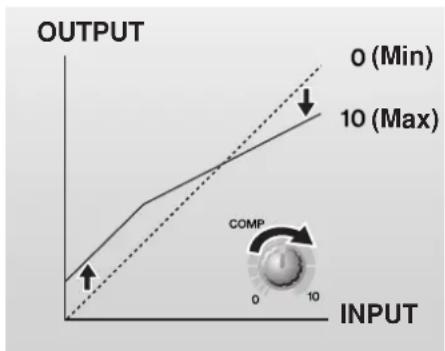
One form of compression known as “limiting” can, when properly used, produce a smooth, unified sound with no excessive peaks or distortion. A common example of the use of compression is to “tame” a vocal that has a wide dynamic range in order to tighten up the mix. With the right amount of compression you’ll be able to clearly hear whispered passages while passionate shouts are still well balanced in the mix. Compression can also be valuable on bass guitar. Too much compression can be a cause of feedback, however, so use it sparingly.
Most compressors require several critical parameters to be set properly to achieve the desired sound. The MG compressor makes achieving great sound much easier: all you need to do is set a single “compression” control and all of the pertinent parameters are automatically adjusted for you.
line
| INPUT | OUTPUT | |-------|--------| | 0 | 0 | | 10 | 10 |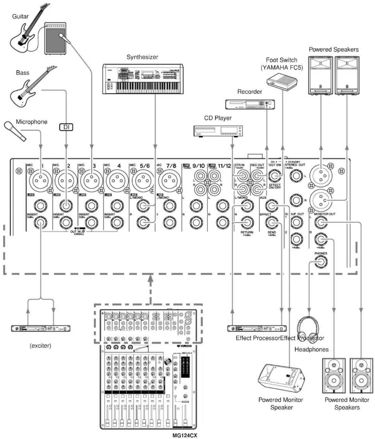
The following applies to both the MG124CX and MG124C. In cases where different features need to be described for each model, the MG124CX feature will be described first, followed by the MG124C feature in brackets: MG124CX (MG124C).
Channel Control Section
Channels
1 to 4
(Monaural)
Channels
5/6 and 7/8
(Ste
Channels
9/10 and 11/12
(Stereo)
MG124CX
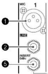
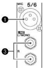
① MIC Input Jacks (CHs 1 to 4, 5/6, 7/8)
These are balanced XLR-type microphone input jacks (1:Ground; 2:Hot; 3:Cold).
② LINE Input Jacks (CHs 1 to 4)
These are balanced TRS phone-jack line inputs (T:Hot; R:Cold; S:Ground).
You can connect either balanced or unbalanced phone plugs to these jacks.
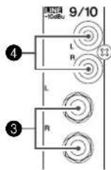
③ LINE Input Jacks (CHs 5/6 to 11/12)
These are unbalanced phone-jack stereo line inputs.
4 LINE Input Jacks (CHs 9/10, 11/12)
These are unbalanced stereo RCA pin jacks.
NOTE Where an input channel provides both a MIC input jack and a LINE input jack, or a LINE input jack and an RCA pin jack, you can use either jack but not both at the same time. Please connect to only one jack on each channel.
⑤ INSERT Jacks (CHs 1 to 4)
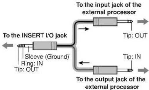
Each of these jacks provides an insert point between the equalizer and fader of the corresponding input channel (CHs 1 to 4). The INSERT jacks can be used to independently connect devices such as graphic equalizers, compressors, or noise filters into the corresponding channels. These are TRS (tip, ring, sleeve) phone jacks that carry both the send and return signal (tip = send/out; ring = return/in; sleeve = ground).
NOTE Patching external devices via an INSERT jack requires a special insert cable such as illustrated below (insert cable sold separately).
flowchart
graph LR
    A["To the INSERT I/O jack"] --> B["Sleeve (Ground)<br>Ring: IN<br>Tip: OUT"]
    B --> C["To the input jack of the external processor"]
    C --> D["Tip: OUT"]
    C --> E["To the output jack of the external processor"]
    E --> F["Tip: IN"]

The signal output from the INSERT jacks is reverse-phased. This should not be a problem when connecting to an effect unit, but please be aware of the possibility of phase conflict when connecting to other types of device.
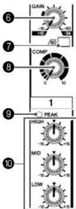
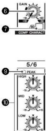
6 GAIN Control
Adjusts the input signal level.
To achieve the best balance between S/N ratio and dynamic range, adjust the level so that the PEAK indicator ⑨ lights only occasionally and briefly on the highest input transients. The -60 to -16 scale is the MIC input adjustment range. The -34 to +10 scale is the LINE input adjustment range.
⑦ /switch (High Pass Filter)
This switch toggles the HPF on or off. To turn the HPF on, press the switch in () The HPF cuts frequencies below 80 Hz (the HPF does not apply to the line inputs of stereo input channels ③④).
8 COMP Control
Adjusts the amount of compression applied to the channel. As the knob is turned to the right the compression ratio increases while the output gain is automatically adjusted accordingly. The result is smoother, more even dynamics because louder signals are attenuated while the overall level is boosted.
NOTE Avoid setting the compression too high, as the higher average output level that results may lead to feedback.
9 PEAK Indicator
The peak level of the post-EQ signal is detected, and the PEAK indicator lights red when the level reaches 3 dB below clipping. For XLR-equipped stereo input channels (5/6 and 7/8), both the post-EQ and post-mic-amp peak levels are detected, and the indicator lights red if either of these levels reaches 3 dB below clipping.
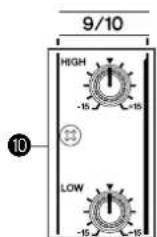
10 Equalizer (HIGH, MID, and LOW)
This three-band equalizer adjusts the channel's high, mid, and low frequency bands. Channels 9/10 and 11/12 have two bands: high and low. Setting the knob to the ▼ position produces a flat response in the corresponding band. Turning the knob to the right boosts the corresponding frequency band, while turning to the left attenuates the band. The following table shows the EQ type, frequency, and maximum cut/boost for each of the three bands.
| Band Type Frequency | Maximum Cut/Boost | |
| HIGH Shelving 10 kHz | ±15 dBMID | |
| LOW Shelving 100 Hz |
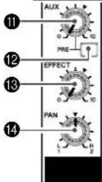
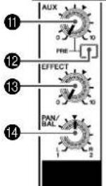
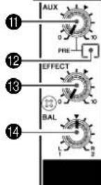
11 AUX (AUX1) Control
Adjusts the level of the signal sent from the channel to the AUX (AUX1) bus. The knob should generally be set close to the ▼ position.
On stereo channels, the signals from the L (odd) and R (even) channels are mixed and sent to the AUX (AUX1) bus.
NOTE To send the signal to the buses set the ON switch to on ( )
12 AUX PRE Switch
Selects whether the pre-fader or the post-fader signal is fed to the AUX (AUX1) bus. If the switch is on (the mixer sends the pre-fader signal (the signal immediately prior to the Channel fader 19) to the AUX (AUX1) bus, so that AUX (AUX1) output is not affected by the fader. If the switch is off (the mixer sends the post-fader signal to the AUX (AUX1) bus.
13 EFFECT (AUX2) Controls
Adjusts the level of the signal sent from the channel to the EFFECT (AUX2) bus. Note that the signal level sent to the bus is also affected by the Channel fader. On stereo channels (5/6, 7/8, 9/10, or 11/12), the signals from the L (odd) and R (even) channels are mixed and then sent to the EFFECT (AUX2) bus.
14 PAN Control (1 to 4) PAN/BAL Control (5/6 and 7/8) BAL Control (9/10 and 11/12)
The PAN control determines the stereo positioning of the channel signal on the Group 1 and 2 buses or on the Stereo L and R buses.
The BAL control knob sets the balance between left and right channels. Signals input to the L input (odd channel) go to the Group 1 bus or to the Stereo L bus; signals input to the R input (even channel) go to the Group 2 bus or the Stereo R bus.
NOTE On channels where this knob provides both PAN and BAL control (channels 5/6 and 7/8), the knob operates as a PAN control when input is received via the MIC jack or L (MONO) input only, and as a BAL control when input is received via both L and R inputs.
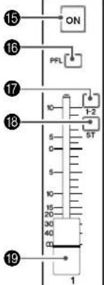
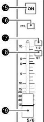
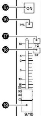
15 ON Switch
Turn this switch on to send the signal to the buses. The switch lights orange when on.
16 PFL (Pre-Fader Listen) Switch
This switch lets you monitor the channel's pre-fader signal. Press the switch in ( ) so that it lights to turn it on. When the switch is on the channel pre-fader signal is output to the PHONES and MONITOR OUT 19 jacks for monitoring.
17 1-2 Switch
This switch assigns the channel's signal to the Group 1 and 2 buses. 2.5kHz .
NOTE To send the signal to the Group buses engage the ON switch ( ).
18 ST Switch
This switch assigns the channel's signal to the Stereo L and R buses.
NOTE To send the signal to the Stereo buses engage the ON switch ( ).
19 Channel Fader
Adjusts the level of the channel signal. Use these faders to adjust the balance between the various channels.
NOTE Set the fader sliders for unused channels all the way down to minimize noise.
Master Control Section

YAMAHA
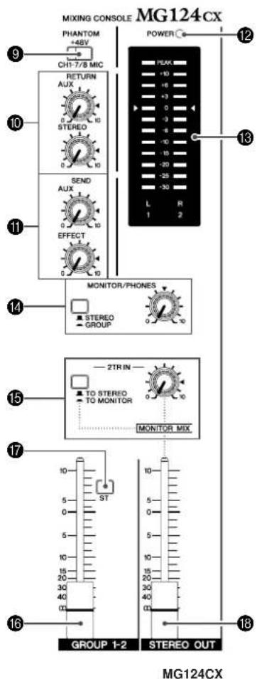
* impedance balanced Since the hot and cold terminals of impedance balanced output jacks have the same impedance, these output jacks are less affected by induced noise.
1 2TR IN Jacks
These RCA pin jacks can be used to input a stereo sound source. Use these jacks when you want to connect a CD player directly to the mixer.
NOTE You can adjust the signal level using the 2TR IN control in the Master Control section.
② REC OUT (L, R) Jacks
These RCA pin jacks can be connected to an external recorder such as an MD recorder in order to record the same signal that is being output via the STEREO OUT jacks.
NOTE The mixer's STEREO OUT Master Fader has no affect on the signal output via these jacks. Be sure to make appropriate level adjustments at the recording device.
③ RETURN L (MONO), R Jacks
These are unbalanced phone-jack type line inputs. The signal received by these jacks is sent to the STEREO L/R buses and the AUX (AUX1) bus. These jacks are typically used to receive the signal returned from an external effect device (reverb, delay, etc.).
NOTE These jacks can also be used as an auxiliary stereo input. If you connect to the L (MONO) jack only, the mixer will recognize the signal as monaural and will send the identical signal to both the L and R jacks.
4 SEND Jacks
• A UX (AUX1)
This is an impedance balanced* phone-jack type output. This jack outputs the signals from AUX (AUX1) bus. You can use this jack, for example, to connect to an effect unit, cue box, or other monitoring system.
• EFFECT (AUX2)
This is an impedance balanced* phone-jack type output that outputs the signal from the EFFECT (AUX2) bus. You can use this jack, for example, to connect to an external effect unit.
⑤ STEREO OUT (L, R) Jacks
These jacks deliver the mixer's stereo output. You can use these jacks, for example, to connect to the power amplifier driving your main speakers. You can also connect these jacks to a recording device when you wish to record mixer's stereo output while using the STEREO OUT Master fader for level control.
• XLR jacks
XLR-type balanced output jacks.
• LINE jacks
TRS phone-jack type balanced outputs.
6 GROUP OUT (1, 2) Jacks
These impedance-balanced* phone jacks output the Group 1/2 signals. Use these jacks to connect to the inputs of a multi-track recorder, external mixer, or other such device.
7 MONITOR OUT Jacks
Connect these stereo phone-jack outputs to your monitor system.
NOTE The signal output by these jacks is determined by the MONITOR switch, the 2TR IN switch, and the PFL switches on the input channels.
8 PHONES Jack
Connect a pair of headphones to this stereo phone jack. The PHONES jack outputs the same signal as the MONITOR OUT jacks.
9 PHANTOM +48 V Switch
This switch toggles phantom power on and off. When the switch is on the mixer supplies +48V phantom power to all channels that have XLR mic input jacks (CHs 1–4, 5/6, 7/8).
Turn this switch on when using one or more phantom-powered condenser microphones.
NOTE When this switch is on the mixer supplies DC +48 V power to pins 2 and 3 of all XLR-type MIC INPUT jacks.

- Be sure to leave this switch off ( ) if you do not need phantom power.
- When tuning the switch on ( ) be sure that only condenser mics are connected to the XLR input jacks (CHs: 1 to 7/8). Devices other than condenser mics may be damaged if connected to the phantom power supply. Note, however, that the switch may be left on when connecting to balanced dynamic microphones.
• To avoid damage to speakers, be sure to turn off amplifiers (or powered speakers) before turning this switch on or off. We also recommend that you turn all output controls (STEREO OUT Master Fader, GROUP 1-2 Fader, etc.) to their minimum settings before operating the switch to avoid the risk of loud noises that could cause hearing loss or device damage.
10 RETURN
• A UX (AUX1) Control
Adjusts the level at which the L/R signal received at the RETURN jacks (L (MONO) and R) is sent to the AUX (AUX2) bus.
- STEREO Control
Adjusts the level at which the signal received at the RETURN jacks (L (MONO) and R) is sent to the STEREO L/R buses.
NOTE If you supply a signal to the RETURN L (MONO) jack only, the mixer sends the same signal to both the L and R Stereo buses.
11 Master SEND
• M aster AUX (AUX1) Control
Adjusts the signal level sent to the AUX (AUX1) SEND jack.
• M aster EFFECT (AUX2) Control
Adjusts the level of the signal sent to the EFFECT (AUX2) bus.
NOTE If you are using the MG124CX, the Master EFFECT control does not affect the level of the signal sent from the EFFECT bus to the internal digital effect processor.
12 POWER Indicator
This indicator lights when the mixer's power is ON.
13 Level Meter
This LED meter displays the level of the signal selected by the MONITOR switch 14, 2TR IN switch 15 and PFL switch. The "0" segment corresponds to the nominal output level. The PEAK segment lights red when the output reaches the clipping level.
14 MONITOR/PHONES
• MONITOR Switch
If this switch is set to GROUP (the Group 1/2 bus signals are sent to the MONITOR OUT jacks, the PHONES jack, and the level meter. If it is set to STEREO (the STEREO L/R bus signals are sent to these jacks and the level meter.
• MONITOR Control
Controls the level of the signal output to the PHONES jack and the MONITOR OUT jacks.
15 2TR IN
- 2TR IN Switch
If this switch is set to TO MONITOR (the signals input via the 2TR IN jacks are sent to the MONITOR OUT jacks, the PHONES jack, and the level meter. If it is set to TO STEREO (the signals are sent to the STEREO L/R buses.
• 2TR IN control
Adjusts the level of the signal sent from the 2TR IN jacks to the STEREO L/R buses.
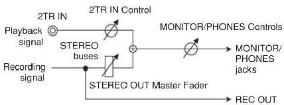
The following illustration shows how the switch settings correspond to the signal selection.
| Switches | Signals output via the MONITOR/PHONES jacks | ||
| PFL | MONITOR/ PHONES | 2TR IN | |
| ON | — — PFL | ||
| OFF | STEREO | TO STEREO | STEREO (+ 2TR IN) |
| TO MONITOR | STEREO + 2TR INMONITOR MIX* | ||
| GROUP | TO STEREO | GROUP | |
| TO MONITOR | GROUP (+ 2TR IN) | ||
* MONITOR/MODubbing, you can adjust the levels of the monitor playback signal and the signal being recorded separately.
MONITOR MIX Signal Flow
flowchart
graph TD
    A["Playback signal"] --> B["2TR IN"]
    B --> C["STEREO buses"]
    C --> D["+"]
    D --> E["MONITOR/PHONES Controls"]
    E --> F["MONITOR/PHONES jacks"]
    G["Recording signal"] --> H["STEREO OUT Master Fader"]
    H --> I["REC OUT"]
    J["STEREO IN Control"] --> D
NOTE If the input channel PFL switch is on ( ), then only the PFL output from that channel is sent to the C-R OUT jacks, PHONES jacks, and level meter.
16 GROUP 1-2 Fader
Adjusts the signal level sent to the GROUP OUT jacks.
17 ST Switch
If this switch is on ( ), the signals are sent to the STEREO L/R buses via the GROUP 1-2 fader 16. The Group 1 signal goes to Stereo L and the Group 2 signal goes to Stereo R.
18 STEREO OUT Master Fader
Adjusts the signal level sent to the STEREO OUT jacks.
DIGITAL EFFECT
*Only the MG124CX has digital effects.
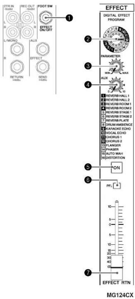
1 FOOT SWITCH Jack
A YAMAHA FC5 foot switch (sold separately) can be connected to this jack and used to toggle the digital effects ON and OFF.
② PROGRAM Dial
Selects one of the 16 internal effects. See page 17 for details about the internal effects.
3 PARAMETER Control
Adjusts the parameter (depth, speed, etc.) for the selected effect. The last value used with each effect type is saved.
NOTE When you change to a different effect type, the mixer automatically restores the value that was previously used with the newly selected effect (regardless of the current position of the PARAMETER Control knob). These parameter values are reset when the power is turned off.
4 AUX Control
Adjusts the level of the signal sent from the internal digital effect unit to the AUX bus.
⑤ ON Switch
Switches the internal effect on or off. The internal effect is applied only if this switch is turned on. The switch lights orange when on. An optional YAMAHA FC5 foot switch (sold separately) can be used to toggle the digital effects ON and OFF.
NOTE The ON switch lights and the internal effect unit is active by default when the power is initially turned on.
6 PFL Switch
Turn this switch on to send the effect signal to the PFL bus.
7 EFFECT RTN Fader
Adjusts the signal level sent from the internal digital effect unit to the STEREO bus.
Rear Input/Output Section
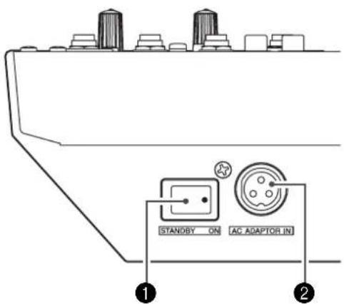
1 POWER Switch
Use this switch to turn the mixer's power ON or to STANDBY mode.

Note that a small current continues to flow while the switch is in the STANDBY position. If you do not plan to use the mixer for a while, be sure to unplug the AC adaptor from the wall outlet.
② AC ADAPTOR IN Connector
Connect the supplied PA-20 power adaptor to this connector (see page 5).

Use only the PA-20 adaptor included with this mixer. Use of a different adaptor may result in fire or electric shock.
Digital Effect Program List
| No Program Parameter Description | |||
| 1 REVERB HALL 1 REVERBTIME | Reverb simulating a large space such as a concert hall. | ||
| 2 REVERB HALL 2 REVERBTIME | |||
| 3 REVERB ROOM 1 REVERBTIME | Reverb simulating the acoustics of a small space (room). | ||
| 4 REVERB ROOM 2 REVERBTIME | |||
| 5 | REVERB STAGE 1 REVERBTIME | Reverb simulating a large stage. | |
| 6 REVERB STAGE 2 REVERBTIME | |||
| 7 | REVERB PLATE | REVERBTIME | Simulation of a metal-plate reverb unit, producing a more hard-edged sound. |
| 8 DRUM AMBIENCE REVERBTIME A short reverb that is ideal for use with kick drum. | |||
| 9 | KARAOKE ECHO | DELAY TIME | Echo designed for karaoke (sing-along) applications. |
| 10 | VOCAL ECHO | DELAY TIME | Echo suitable for vocals. |
| 11 | CHORUS 1 | LFO Frequency | Creates a thick sound by modulating the delay time.The PARAMETER control adjusts the frequency of the LFO* that modulates the delay time. |
| 12 | CHORUS 2 | LFO Frequency | |
| 13 | FLANGER | LFO Frequency | A sweeping pitched effect.The PARAMETER control adjusts the frequency of the LFO* that modulates the delay time. |
| 14 | PHASER | LFO Frequency | Phase modulation produces a cyclical phasing effect.The PARAMETER control adjusts the frequency of the LFO* that modulates the delay time. |
| 15 | AUTO WAH | LFO Frequency | A wah-wah effect with cyclical filter modulation.The PARAMETER control adjusts the frequency of the LFO* that modulates the delay time. |
| 16 | DISTORTION | DRIVE | Adds a sharp-edged distortion to the sound. |
* "LFO" stands for Low Frequency Oscillator. An LFO is normally used to modulate another signal, determining the modulation speed and waveform shape.
Jack List
| Input and Output Jacks | Polarities | Configurations |
| MIC INPUT, STEREO OUT | Pin 1: GroundPin 2: Hot (+)Pin 3: Cold (−) | INPUT OUTPUT  |
| LINE INPUT(CH1 to 4)GROUP OUT, STEREO OUT,MONITOR OUT, AUX (AUX1),EFFECT (AUX2)* | Tip: Hot (+)Ring: Cold (−)Sleeve: Ground | 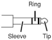 |
| INSERT | Tip: OutputRing: InputSleeve: Ground | |
| PHONES | Tip: LRing: RSleeve: Ground | |
| RETURNLINE INPUT (CH5/6 to 11/12) | Tip: HotSleeve: Ground | 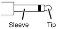 |
* These jacks will also accept connection to monaural phone plugs. If you use monaural plugs, the connection will be unbalanced.
| ■ Power doesn’t come on. | □ Is the supplied power adaptor properly plugged into an appropriate AC wall outlet?□ Is the supplied power adaptor properly plugged into the mixer? |
| ■ No sound. | □ Are microphones, external devices, and speakers connected correctly?□ Are the ON switch and ST switch of the channels you are using turned ON?□ Are the channel GAIN controls, Channel fader, STEREO OUT master fader and GROUP 1-2 fader set to appropriate levels?□ Are the MONITOR switch and 2TR IN switch set properly?□ Are your speaker cables connected properly, or are they shorted?□ If the above checks do not identify the problem, call Yamaha for service.(Refer to the page 71 for a list of service centers.) |
| ■ Sound is faint, distorted, or noisy. | □ Are the channel GAIN controls, Channel fader, STEREO OUT master fader and GROUP 1-2 fader set to appropriate levels?□ Are two different instruments connected to the XLR-type and phone jacks, or to the phone and RCA pin jacks on one channel? Please connect to only one of these jacks on each channel.□ Is the input signal from the connected device set to an appropriate level?□ Are you applying the effects at an appropriate level?□ Are microphones connected to the MIC input jacks on channels 1 to 7/8?□ If you are using condenser microphones, is the PHANTOM +48 V switch turned ON? |
| ■ No effect is applied.(If you are using MG124CX) | □ Check that the EFFECT control on each channel is correctly adjusted.□ Be sure that the internal effect unit’s ON switch is turned ON.□ Be sure that the EFFECT PARAMETER control and EFFECT RTN fader are correctly adjusted. |
| ■ I want spoken words to be heard more clearly. | □ Be sure that the switches are ON.□ Adjust the equalizers (HIGH, MID and LOW) on each channel. |
| ■ I want to output a monitor signal through speakers. | □ Connect a powered speaker to the AUX (AUX1) jack* and turn the PRE switch on each channel ON. Then adjust the output signal by using the AUX (AUX1) controls on each channel and the Master SEND control. |
* The MG124CX feature is described first, followed by the MG124C feature in brackets: MG124CX (MG124C).
■ Electrical Specifications
| MIN TYP | MAX | UNIT | |||
| Frequency Response STEREO OUT GAIN: min (CHs 1-7/8) | |||||
| 20 Hz-20 kHzNominal output level @1 kHzInput: CHs 1 to 11/12, RETURN, 2TR IN | -3.0 | 0.0 1.0 dB | |||
| Total Harmonic Distortion (THD + N) | STEREO OUT | +14 dBu @ 20 Hz-20 kHz, Input GAIN Control at minimum | 0.1 % | ||
| Hum & Noise Hum & Noise are measured with a 6 dB/octave filter @ 12.7 kHz; equivalent to a 20 kHz filter with infinite dB/octave attenuation. | CH INPUT 1-4 MIC | EIN (Equivalent Input Noise): Rs = 150 Ω, GAIN: maximum | -128 | ||
| STEREO OUT | STEREO OUT, GROUP Master fader at nominal level and all channels' ST and 1-2 switches off. | -88 | |||
| GROUP OUT | |||||
| EFFECT/AUX (AUX1, 2*) SEND | Master EFFECT/AUX (AUX1, 2) control at nominal level and all CH EFFECT/AUX (AUX1, 2) controls at minimum. | -81 | |||
| STEREO OUT | STEREO OUT, GROUP Master fader and one CH fader at nominal level. | -64 | |||
| GROUP OUT | |||||
| STEREO OUT | Residual Output Noise -98 | ||||
| Crosstalk (1 kHz) Adjacent Input CHs 1-4 -70 | |||||
| Maximum voltage gain (1 kHz)All faders and controls are maximum when measured.PAN/BAL: panned hard left or hard right | Rs = 150 ΩINPUT GAIN: maximum | MIC to CH INSERT OUT 60 | |||
| MIC to STEREO OUT | 84 | ||||
| MIC to GROUP OUT | |||||
| MIC to GROUP to ST | 94 | ||||
| MIC to REC OUT | 62.2 | ||||
| MIC to MONITOR OUT, ST TO MONITOR | 94 | ||||
| MIC to PHONES OUT | 83 | ||||
| MIC to AUX (AUX1*) SEND PRE | 76 | ||||
| MIC to AUX (AUX1*) SEND POST, EFFECT (AUX2*) SEND | 86 | ||||
| CH 5/6, 7/8 LINE to STEREO OUT | 58 | ||||
| CH 5/6, 7/8 LINE to GROUP OUT | |||||
| CH 5/6, 7/8 AUX (AUX1*) SEND PRE | 47 | ||||
| CH 5/6, 7/8 LINE to AUX (AUX1*) SEND POST, EFFECT (AUX2*) SEND | 57 | ||||
| CH 9/10, 11/12 to STEREO OUT | 34 | ||||
| CH 9/10, 11/12 to GROUP OUT | |||||
| Rs = 150 Ω | RETURN to STEREO OUT | 16 | |||
| RETURN to EFFECT (AUX2*) SEND | 9 | ||||
| Rs = 600 Ω | 2TR IN to STEREO OUT | 27.8 | |||
| Phantom Voltage | MIC | no load | 48 | ||
■ General Specifications
| Input HPF | CHs 1-7/8, 80 Hz, 12 dB/oct | |
| Input equalization±15 dB maximumTurn over/roll-off frequencyof shelving: 3 dB blow maxi-mum variable level. | CHs 1-7/8 | HIGH: 10 kHz (shelving)MID: 2.5 kHz (peaking)LOW: 100 Hz (shelving) |
| CH 9/10-11/12 | HIGH: 10 kHz (shelving)LOW: 100 Hz (shelving) | |
| PEAK Indicator | Red LED turns on when post EQ signal (either post MIC HA or post EQ signal for CHs 5/6, 7/8) reaches -3 dB below clipping (+17 dBu). | |
| Internal Digital Effect* | 16 PROGRAM, PARAMETER controlFoot Switch (Digital Effect On/Off) | |
| LED Level Meter | Pre MONITOR Level | 2x12 points LED meter (PEAK, +10, +6, +3, 0, -3, -6, -10, -15, -20, -25, -30 dB)PEAK lights if the signal level reaches 3 dB below the clipping level. |
| Power Supply Adaptor | PA-20 | AC 35 VCT, 0.94 A, Cable Length = 3.6 m |
| Power Consumption | 30 W | |
| Dimensions (W x H x D) | 346.2 mm x 86.1 mm x 436.6 mm | |
| Net Weight | 3.2 kg (MG124CX), 3 kg (MG124C) | |
All faders are nominal if not specified.
Output impedance of signal generator: 150 ohms
* The MG124CX feature is described first, followed by the MG124C feature in brackets: MG124CX (MG124C)
■ Input Specifications
| Input Connectors | Gain | Input Impedance | Appropriate Impedance | Sensitivity * Nominal Level | Max. before Clipping | Connector Specifications | |
| CH INPUT MIC (CHs 1-4) | -60 dB | 3kΩ | 50–600Ω Mics | -80 dBu (0.078 mV) | -60 dBu (0.775 mV) -40 dBu (7.75 mV) | XLR-3-31 type (balanced [1 = GND, 2 = HOT, 3 = COLD]) | |
| -16 dB | -36 dBu (12.3 mV) -1 | 6 dBu (123 mV) +4 dBu (1.23 V) | |||||
| CH INPUT LINE (CHs 1-4) | -34 dB | 10kΩ | 600Ω Lines | -54 dBu (1.55 mV) -34 dBu (15.5 mV) -14 dBu (155 mV) | TRS phone jack (balanced [Tip = HOT, Ring = COLD, Sleeve = GND]) | ||
| +10 dB | -10 dBu (245 mV) +10 dBu (2.45 V) +30 dBu (24.5 V) | ||||||
| ST CH MIC INPUT (CHs 5/6, 7/8) | -60 dB | 3kΩ | 50–600Ω Mics | -80 dBu (0.078 mV) | -60 dBu (0.775 mV) -40 dBu (7.75 mV) | XLR-3-31 type (balanced [1 = GND, 2 = HOT, 3 = COLD]) | |
| -16dB | -36 dBu (12.3 mV) -16 dBu (123 mV) -6 dBu (389 mV) | ||||||
| ST CH LINE INPUT (CHs 5/6, 7/8) | -34 dB | 10kΩ | 600Ω Lines | -54 dBu (1.55 mV) -34 dBu (15.5 mV) -14 dBu (155 mV) | Phone jack (unbalanced) | ||
| +10 dB | -10 dBu (245 mV) +10 dBu (2.45 V) +30 dBu (24.5 V) | ||||||
| ST CH INPUT (CHs 9/10, 11/12) | — 10kΩ | 600Ω Lines | -30 dBu (24.5 mV) -10 dBu (245 mV) +10 dBu (2.45 V) | Phone jack (unbalanced)RCA pin jack | |||
| CH INSERT IN (CHs 1-4) | — 10kΩ | 600Ω Lines | -20 dBu (77.5 mV) 0 dBu (0.775 V) +20 dBu (7.75 V) | TRS phone Jack (unbalanced [Tip = Out, Ring = In, Sleeve = GND]) | |||
| RETURN (L, R) — | 10kΩ | 600Ω Lines | -12 dBu (195 mV) +4 dBu (1.23 V) +24 dBu (12.3 V) | Phone jack (unbalanced) | |||
| 2TR IN (L, R) — | 10kΩ | 600Ω Lines | -26 dBV (50.1 mV) -10dBV (0.316V) +10dBV (3.16 V) | RCA pin jack | |||
Where 0 dBu = 0.775 Vrms and 0 dBV = 1 Vrms
* Sensitivity : The lowest level that will produce an output of +4 dB (1.23 V), or the nominal output level when the unit is set to the maximum level. (All faders and level controls are at their maximum position.)
■ Output Specifications
| Output Connectors | Output Impedance | Appropriate Impedance | Nominal Level | Max. before clipping | Connector Specifications |
| STEREO OUT (L, R) | 75Ω | 600Ω Lines | +4dBu (1.23 V) | +24 dBu (12.3 V) | XLR-3-32 type (balanced [1 = GND, 2 = HOT, 3 = COLD])Phone Jack (balanced [Tip = HOT, Ring = COLD, Sleeve = GND]) |
| GROUP OUT (1, 2) | 150Ω | 10kΩ Lines | +4dBu (1.23 V) | +20 dBu (7.75 V) | Phone jack (impedance balanced [Tip = HOT, Ring = COLD, Sleeve = GND]) |
| EFFECT/AUX (AUX1, 2*) SEND | 150Ω | 10kΩ Lines | +4dBu (1.23 V) | +20 dBu (7.75 V) | Phone jack (impedance balanced [Tip = HOT, Ring = COLD, Sleeve = GND]) |
| CH INSERT OUT (CHs 1-4) | 75Ω | 10kΩ Lines | 0 dBu (0.775 V) | +20 dBu (7.75 V) | Phone jack (unbalanced [Tip = Out, Ring = In, Sleeve = GND]) |
| REC OUT (L, R) | 600Ω | 10kΩ Lines | -10 dBV (0.316 V) | +10 dBV (3.16 V) | RCA pin jack |
| MONITOR OUT (L, R) | 150Ω | 10kΩ Lines | +4 dBu (1.23 V) | +20 dBu (7.75 V) | Phone jack (impedance balanced [Tip = HOT, Ring = COLD, Sleeve = GND]) |
| PHONES OUT | 100Ω | 40Ω Phones | 3 mW | 75 mW | Stereo phone jack |
Where 0 dBu = 0.775 Vrms and 0 dBV = 1 Vrms
* The MG124CX feature is described first, followed by the MG124C feature in brackets: MG124CX (MG124C)
■ Dimensional Diagrams
■ Block Diagram and Level Diagram
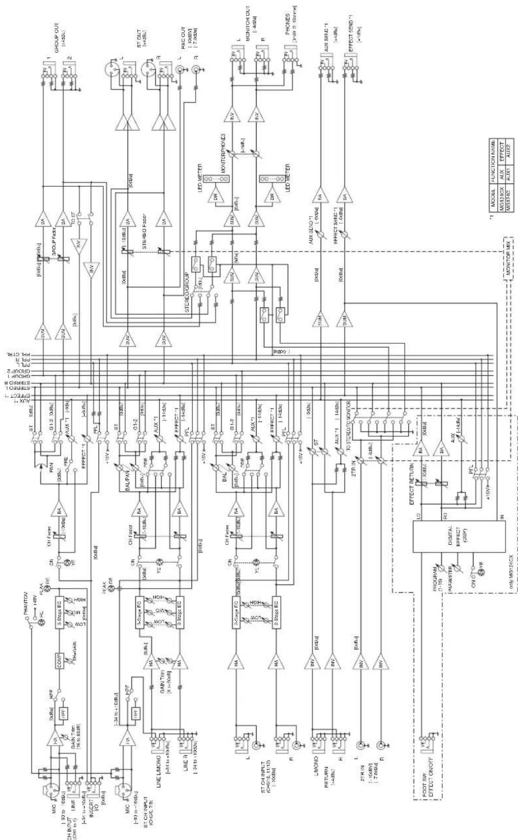
flowchart
graph TD
    subgraph CH_INPUT
        A["CH INPUT (CH1 to 4)"]
        B["LINE"]
        C["INSERT I/O"]
        D["MIC (-93 to -60dB)"]
        E["ST CH INPUT (CH-5C, 7B)"]
        F["LINE L/MONO (-34 to +10dB)"]
        G["LINE R (-34 to +10dB)"]
        H["L"]
        I["ST CH INPUT (CH51C, 11:123) (-10dB)"]
        J["L/MONO (-48dB)"]
        K["RETURN (-10dB)"]
        L["3TR IN (-7.8dB)"]
        M["FOOT SW EFFECT ON/OFF"]
    end

    subgraph ST_OUT
        N["ST OUT (-4dB)"]
        O["REC OUT (-10dB)"]
        P["R"]
        Q["L"]
        R["R"]
        S["L MONITOR OUT (-4dB)"]
        T["R"]
        U["PHONES (3W @ 380nm)"]
        V["AUX SEND *1 (+4dB)"]
        W["EFFECT SEND *1 (+4dB)"]
    end

    subgraph RED_CUT
        X["RED OUT (-7.8dB)"]
        Y["RED OUT (-7.8dB)"]
        Z["RED OUT (-7.8dB)"]
    end

    subgraph ST_RECO
        AA["ST RECO GROUP"]
        AB["LED METER"]
        AC["MONITOR PHONES"]
        AD["LED METER"]
    end

    subgraph TEST_OUT
        AE["TEST OUT (-4dB)"]
        AF["TEST OUT (-4dB)"]
        AG["TEST OUT (-4dB)"]
    end

    subgraph REM_OUT
        AH["REDACT"]
        AI["REDACT"]
    end

    subgraph LO_OUT
        AJ["LO_OUT"]
        AK["LO_OUT"]
    end

    subgraph REF_OUT
        AL["REF_OUT"]
    end

    subgraph CONTROL_Factor
        AM["GAIN Trim (-8 to 50dB)"]
        AN["GAIN Trim (-8 to 50dB)"]
        AO["GAIN Trim (-8 to 50dB)"]
    end

    subgraph REF_OUT
        AP["PERF"]
        AQ["PHAVTOV"]
        AR["HLP"]
        AS["FLAM"]
        AT["ON"]
        AU["CH Faster"]
        AV["BA"]
        AW["ST"]
        AX["PRE"]
        AY["AUX *1"]
        AZ["EFFECT *1"]
    end

    subgraph REF_OUT
        BA --> BA1["+15V"]
        BA --> BA2["+15V"]
        BA --> BA3["+15V"]
        BA --> BA4["+15V"]
        BA --> BA5["+15V"]
        BA --> BA6["+15V"]
        BA --> BA7["+15V"]
    end

    subgraph CONTROL_Factor
        BQ["G1-2 (-9dB)"]
        BQ --> BQ1["AUX *1 (-9dB)"]
        BQ --> BQ2["EFFECT *1 (-9dB)"]
    end

    subgraph REF_OUT
        BQ --> BQ1
        BQ --> BQ2
        BQ --> BQ3["AUX *1 (-10dB)"]
        BQ --> BQ4["EFFECT *1 (-10dB)"]
    end

    subgraph CONTROL_Factor
        BQ --> BQ5["AUX *1 (-9dB)"]
        BQ --> BQ6["EFFECT *1 (-9dB)"]
    end

    subgraph REF_OUT
        BQ --> BQ7["AUX *1 (-10dB)"]
        BQ --> BQ8["EFFECT *1 (-10dB)"]
    end

    subgraph CONTROL_Factor
        BQ --> BQ9["AUX *1 (-9dB)"]
        BQ --> BQ10["EFFECT *1 (-9dB)"]
    end

    subgraph REF_OUT
        BQ --> BQ10
        BQ --> BQ11["AUX *1 (-10dB)"]
        BQ --> BQ12["EFFECT *1 (-10dB)"]
    end

    subgraph CONTROL_Factor
        BQ --> BQ12
        BQ --> BQ13["AUX *1 (-9dB)"]
        BQ --> BQ14["EFFECT *1 (-9dB)"]
    end

    subgraph REF_OUT
        BQ --> BQ14
        BQ --> BQ15["AUX *1 (-9dB)"]
        BQ --> BQ16["EFFECT *1 (-9dB)"]
    end

    subgraph CONTROL_Factor
        BQ --> BQ16
        BQ --> BQ17["AUX *1 (-9dB)"]
        BQ --> BQ18["EFFECT *1 (-9dB)"]
    end

    subgraph REF_OUT
        BQ --> BQ18
        BQ --> BQ19["AUX *1 (-9dB)"]
        BQ --> BQ20["EFFECT *1 (-9dB)"]
    end

    subgraph CONTROL_Factor
        BQ --> BQ20
        BQ --> BQ21["AUX *1 (-9dB)"]
        BQ --> BQ22["EFFECT *1 (-9dB)"]
    end

    subgraph REF_OUT
        BQ --> BQ22
        BQ --> BQ23["AUX *1 (-9dB)"]
        BQ --> BQ24["EFFECT *1 (-9dB)"]
    end

    subgraph CONTROL_Factor
        BQ --> BQ24
        BQ --> BQ25["AUX *1 (-9dB)"]
        BQ --> BQ26["EFFECT *1 (-9dB)"]
    end

    subgraph REF_OUT
        BQ --> BQ26
        BQ --> BQ27["AUX *1 (-9dB)"]
        BQ --> BQ28["EFFECT *1 (-9dB)"]
    end

    subgraph CONTROL_Factor
        BQ --> BQ28
        BQ --> BQ29["AUX *1 (-9dB)"]
        BQ --> BQ30["EFFECT *1 (-9dB)"]
    end

    subgraph REF_OUT
        BQ --> BQ30
        BQ --> BQ31["AUX *1 (-9dB)"]
        BQ --> BQ32["EFFECT *1 (-9dB)"]
    end

    subgraph CONTROL_Factor
        BQ --> BQ32
        BQ --> BQ33["AUX *1 (-9dB)"]
        BQ --> BQ34["EFFECT *1 (-9dB)"]
    end

    subgraph REF_OUT
        BQ --> BQ34
        BQ --> BQ35["AUX *1 (-9dB)"]
        BQ --> BQ36["EFFECT *1 (-9dB)"]
    end

    subgraph CONTROL_Factor
        BQ --> BQ36
        BQ --> BQ37["AUX *1 (-9dB)"]
        BQ --> BQ38["EFFECT *1 (-9dB)"]
    end

    subgraph REF_OUT
        BQ --> BQ38
        BQ --> BQ39["AUX *1 (-9dB)"]
        BQ --> BQ40["EFFECT *1 (-9dB)"]
    end

    subgraph CONTROL_Factor
        BQ --> BQ40
        BQ --> BQ41["AUX *1 (-9dB)"]
        BQ --> BQ42["EFFECT *1 (-9dB)"]
    end

    subgraph REF_OUT
        BQ --> BQ40
        BQ --> BQ41
        BQ --> BQ42
        BQ --> BQ43["AUX *1 (-9dB)"]
        BQ --> BQ44["EFFECT *1 (-9dB)"]
    end

    subgraph CONTROL_Factor
        BQ --> BQ40
        BQ --> BQ41
        BQ --> BQ42
        BQ --> BQ43
    end

    subgraph REF_OUT
        A["MODEL FUNCTION NAME MG124CX AUX EFFECT MG124C AUX1 AUX2"]

    A -->|MODEL FUNCTION NAME| A0["MODEL FUNCTION NAME MG124CX AUX EFFECT MG124C AUX1 AUX2"]

    style CH_INPUT fill:#f9f,stroke:#333,stroke-width:2px
    style LINE fill:#ccf,stroke:#333,stroke-width:2px
    style INSERT fill:#cfc,stroke:#333,stroke-width:2px
    style I/O fill:#fcc,stroke:#333,stroke-width:2px

For details of products, please contact your nearest Yamaha representative or the authorized distributor listed below.
Yamaha Canada Music Ltd.
135 Milner Avenue, Scarborough, Ontario,
MIS 3R1, Canada
Tel: 416-298-1311
U.S.A.
Yamaha Corporation of America
6600 Orangethorpe Ave., Buena Park, Calif.
90620, U.S.A
Tel: 714-522-9011
CENTRAL & SOUTH AMERICA
MEXICO
PANAMA AND OTHER LATIN
AMERICAN COUNTRIES/
CARIBBEAN COUNTRIES
Yamaha Music Latin America, S.A.
Torre Banco General, Piso 7,
Sherbourne Drive, Tilbrook, Milton Keynes,
MK7 8BL, England
Tel: 01908-366700
GERMANY
Yamaha Music Central Europe GmbH
Siemensstraße 22-34, 25462 Rellingen, Germany
Tel: 04101-3030
Branch Austria, CEE Department
Schleiergasse 20, A-1100 Wien, Austria
Tel: 01-602039025
POLAND
Yamaha Music Central Europe GmbH
YS Copenhagen Liaison Office
Generatorvej 6A
DK-2730 Herlev, Denmark
Tel: 44 92 49 00
NORWAY
OTHER EUROPEAN COUNTRIES
Yamaha Music Central Europe GmbH
Siemensstraße 22-34, 25462 Rellingen, Germany
Tel: +49-4101-3030
AFRICA
Yamaha Corporation,
Asia-Pacific Music Marketing Group
Nakazawa-cho 10-1, Hamamatsu,
Japan 430-8650
Tel: +81-53-460-2313
MIDDLE EAST
TURKEY/CYPRUS
Yamaha Music Central Europe GmbH
Siemensstraße 22-34, 25462 Rellingen, Germany
Tel: 04101-3030
OTHER COUNTRIES
Yamaha Music Gulf FZE
LB21-128 Jebel Ali Freezone
P.O.Box 17328, Dubai, U.A.E.
Tel: +971-4-881-5868
ASIA
THE PEOPLE'S REPUBLIC OF CHINA
Yamaha Music & Electronics (China)
Co., Ltd.
25/F., United Plaza, 1468 Nanjing Road (West),
Jingan, Shanghai, China
Tel: 021-6247-2211
INDONESIA
PT. Yamaha Music Indonesia (Distributor)
PT. Nusantik
Gedung Yamaha Music Center, Jalan Jend. Gatot
Subroto Kav. 4, Jakarta 12930, Indonesia
Tel: 21-520-2577
KOREA
Yamaha Music Korea Ltd.
Tong-Yang Securities Bldg. 16F 23-8
Yoido-dong, Youngdungpo-ku, Seoul, Korea
Tel: 02-3770-0660
MALAYSIA
Yamaha Music Malaysia, Sdn., Bhd.
Lot 8, Jalan Perbandaran, 47301 Kelana Jaya,
Petaling Jaya, Selangor, Malaysia
Tel: 3-78030900
SINGAPORE
Yamaha Music Asia Pte., Ltd.
03-11 A-Z Building
140 Paya Lebor Road, Singapore 409015
Tel: 747-4374
TAIWAN
Yamaha KHS Music Co., Ltd.
3F, #6, Sec.2, Nan Jing E. Rd. Taipei.
Taiwan 104, R.O.C.
Tel: 02-2511-8688
THAILAND
Siam Music Yamaha Co., Ltd.
891/1 Siam Motors Building, 15-16 floor
Rama 1 road, Wangmai, Pathumwan
Bangkok 10330, Thailand
Tel: 02-215-2626
OTHER ASIAN COUNTRIES
Yamaha Corporation,
Asia-Pacific Music Marketing Group
Nakazawa-cho 10-1, Hamamatsu,
Japan 430-8650
Tel: +81-53-460-2317
OCEANIA
AUSTRALIA
Yamaha Music Australia Pty. Ltd.
Level 1, 99 Queensbridge Street, Southbank,
Victoria 3006, Australia
Tel: 3-9693-5111
COUNTRIES AND TRUST
TERRITORIES IN PACIFIC OCEAN
Yamaha Corporation,
Asia-Pacific Music Marketing Group
Nakazawa-cho 10-1, Hamamatsu,
Japan 430-8650
Tel: +81-53-460-2313
YAMAHA
Yamaha Pro Audio global web site:
http://www.yamahaproaudio.com/
Yamaha Manual Library
- Funktionen
- Connecting the Plug and Cord
- FCC INFORMATION (U.S.A.)
- IMPORTANT NOTICE: DO NOT MODIFY THIS UNIT!
- PRECAUTIONS
- PLEASE READ CAREFULLY BEFORE PROCEEDING
- WARNING
- Power supply/Power cord
- Do not open
- Water warning
- If you notice any abnormality
- CAUTION
- Location
- Connections
- Handling caution
- Introduction
- Contents
- Introduction 5
- Mixer Basics
- Quick Guide...... 6
- Making the Most of Your Mixer...... 8
- ■ Reference
- Setup 11
- Front & Rear Panels.... 12
- Troubleshooting.... 18
- Specifications...... 67
- Accessories
- Before Turning on the Mixer
- Be sure that the mixer's power switch is in the STANDBY position.
- Connect the power adaptor to the AC ADAPTOR IN connector (①) on the rear of the mixer, and then turn the fastening ring clockwise (②) to secure the connection.
- Plug the power adaptor into a standard household power outlet.
- Turning the Power On
- Getting Sound to the Speakers
- NOTE
- Balanced, Unbalanced—What's the Difference?
- Signal Levels and the Decibel
- To EQ or Not to EQ
- Cut for a Cleaner Mix
- Some Frequency Facts
- Boost with Caution
- Ambience
- Reverb and Delay Time
- Reverb Tone
- Reverb Level
- The Modulation Effects:
- Phasing, Chorus, and Flanging
- Compression
- Channel Control Section
- ⑦ /switch (High Pass Filter)
- COMP Control
- PEAK Indicator
- Equalizer (HIGH, MID, and LOW)
- AUX (AUX1) Control
- AUX PRE Switch
- EFFECT (AUX2) Controls
- PAN Control (1 to 4) PAN/BAL Control (5/6 and 7/8) BAL Control (9/10 and 11/12)
- ON Switch
- PFL (Pre-Fader Listen) Switch
- 1-2 Switch
- ST Switch
- Channel Fader
- Master Control Section
- 2TR IN Jacks
- ② REC OUT (L, R) Jacks
- ③ RETURN L (MONO), R Jacks
- SEND Jacks
- • A UX (AUX1)
- • EFFECT (AUX2)
- ⑤ STEREO OUT (L, R) Jacks
- • XLR jacks
- • LINE jacks
- GROUP OUT (1, 2) Jacks
- MONITOR OUT Jacks
- PHONES Jack
- PHANTOM +48 V Switch
- RETURN
- • A UX (AUX1) Control
- - STEREO Control
- Master SEND
- • M aster AUX (AUX1) Control
- • M aster EFFECT (AUX2) Control
- POWER Indicator
- Level Meter
- MONITOR/PHONES
- • MONITOR Switch
- • MONITOR Control
- 2TR IN
- - 2TR IN Switch
- • 2TR IN control
- GROUP 1-2 Fader
- ST Switch
- STEREO OUT Master Fader
- DIGITAL EFFECT
- FOOT SWITCH Jack
- ② PROGRAM Dial
- PARAMETER Control
- AUX Control
- ⑤ ON Switch
- PFL Switch
- EFFECT RTN Fader
- Rear Input/Output Section
- POWER Switch
- ② AC ADAPTOR IN Connector
- ■ Dimensional Diagrams
- U.S.A.
- CENTRAL & SOUTH AMERICA
- MEXICO
- PANAMA AND OTHER LATIN
- AMERICAN COUNTRIES/
- CARIBBEAN COUNTRIES
- GERMANY
- POLAND
- NORWAY
- OTHER EUROPEAN COUNTRIES
- AFRICA
- MIDDLE EAST
- TURKEY/CYPRUS
- OTHER COUNTRIES
- ASIA
- THE PEOPLE'S REPUBLIC OF CHINA
- INDONESIA
- KOREA
- MALAYSIA
- SINGAPORE
- 03-11 A-Z Building
- TAIWAN
- THAILAND
- OTHER ASIAN COUNTRIES
- OCEANIA
- AUSTRALIA
- COUNTRIES AND TRUST
- TERRITORIES IN PACIFIC OCEAN
- YAMAHA
Brand : YAMAHA
Model : MG124
Category : Blender