
MGP16X - Blender YAMAHA - Free user manual and instructions
Find the device manual for free MGP16X YAMAHA in PDF.


| Product Type | Analog Mixing Console |
| Brand | Yamaha |
| Model | MGP16X |
| Dimensions (W x H x D) | 447 mm x 143 mm x 495 mm (17.6" x 5.6" x 19.5") |
| Weight | 9.0 kg (19.8 lb) |
| Power Supply | 100–240 V, 50/60 Hz, 55 W max |
| Number of Input Channels | 16 (8 mono, 4 stereo, 4 stereo) |
| Microphone Preamplifier | D-PRE Discrete Class-A with inverted Darlington circuit |
| Equalizer | 3-band: HIGH (8kHz shelving), MID (250Hz–5kHz sweep peaking), LOW (125Hz shelving) |
| Built-in Digital Effects | REV-X (8 types) and SPX (16 types) |
| Compressor | Single-knob per channel (ratio, threshold, output gain) |
| Special Functions | Ducker, Leveler, Stereo Image (on stereo channels) |
| USB Port | Dedicated for iPod/iPhone connection and charging |
| Phantom Power | +48 V (switchable per channel group) |
| High-Pass Filter | 100 Hz, 12 dB/octave (switchable per mono channel) |
| Frequency Response | 20 Hz–20 kHz, +0.5/-1.0 dB |
| Total Harmonic Distortion | 0.02% (STEREO OUT, +14 dBu @20 Hz–20 kHz) |
| Equivalent Input Noise (EIN) | -128 dBu (Rs=150 ohms, gain max) |
| Maximum Voltage Gain | 84 dB (MIC to STEREO OUT) |
| Cleaning | Use only a dry, soft cloth. No solvents or chemical wipes. |
| Safety | Do not open cover. No user-serviceable parts. Refer servicing to qualified personnel. |
| Repairability | Service by qualified Yamaha service personnel only. |
Frequently Asked Questions - MGP16X YAMAHA
User questions about MGP16X YAMAHA
0 question about this device. Answer the ones you know or ask your own.
Ask a new question about this device
Download the instructions for your Blender in PDF format for free! Find your manual MGP16X - YAMAHA and take your electronic device back in hand. On this page are published all the documents necessary for the use of your device. MGP16X by YAMAHA.
USER MANUAL MGP16X YAMAHA
Thank you for your purchase of the Yamaha MGP16X or MGP12X mixing console.
Please read this manual thoroughly to make the best use of the mixing console for the longest possible period of time.
After reading this manual, please keep it available for future reference.
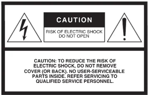
The above warning is located on the rear of the unit.
Explanation of Graphical Symbols
The lightning flash with arrowhead symbol within an equilateral triangle is intended to alert the user to the presence of uninsulated “dangerous voltage” within the product’s enclosure that may be of sufficient magnitude to constitute a risk of electric shock to persons.

The exclamation point within an equilateral triangle is intended to alert the user to the presence of important operating and maintenance (servicing) instructions in the literature accompanying the product.
IMPORTANT SAFETY INSTRUCTIONS
1 Read these instructions.
2 Keep these instructions.
3 Heed all warnings.
4 Follow all instructions.
5 Do not use this apparatus near water.
6 Clean only with dry cloth.
7 Do not block any ventilation openings. Install in accordance with the manufacturer's instructions.
8 Do not install near any heat sources such as radiators, heat registers, stoves, or other apparatus (including amplifiers) that produce heat.
9 Do not defeat the safety purpose of the polarized or grounding-type plug. A polarized plug has two blades with one wider than the other. A grounding type plug has two blades and a third grounding prong. The wide blade or the third prong are provided for your safety. If the provided plug does not fit into your outlet, consult an electrician for replacement of the obsolete outlet.
10 Protect the power cord from being walked on or pinched particularly at plugs, convenience receptacles, and the point where they exit from the apparatus.
11 Only use attachments/accessories specified by the manufacturer.
12 Use only with the cart, stand, tripod, bracket, or table specified by the manufacturer, or sold with the apparatus. When a cart is used, use caution when moving the cart/apparatus combination to avoid injury from tip-over.
13 Unplug this apparatus during lightning storms or when unused for long periods of time.
14 Refer all servicing to qualified service personnel. Servicing is required when the apparatus has been damaged in any way, such as power-supply cord or plug is damaged, liquid has been spilled or objects have fallen into the apparatus, the apparatus has been exposed to rain or moisture, does not operate normally, or has been dropped.

WARNING
TO REDUCE THE RISK OF FIRE OR ELECTRIC SHOCK, DO NOT EXPOSE THIS APPARATUS TO RAIN OR MOISTURE.
(UL60065_03)
ContentsMain Features
Sophisticated analog circuits D-PRE (Discrete Class-A MIC preamp)
Mono input channels are equipped with Class-A discrete microphone preamplifiers.
The head amplifier features an inverted Darlington circuit* used in high-end audio devices, and reproduces low frequencies with exceptionally musical characteristics as well as sustained high frequencies. Independent toggle switching of +48V phantom power and 26dB (pad) on each channel.
* Inverted Darlington circuit: An amplifying method for eliminating the nonlinear characteristics of the amplifier element and suppressing the distortion. The circuit features highly musical phase characteristics.
EQ (equalizer)
The shelving EQ (low/high) on the mono input channels features Xpressive EQ, which effectively models analog EQ utilizing Yamaha's famed VCM (Virtual Circuitry Modeling) technology. We analyzed vintage EQ analog circuits and redesigned the technology specifically for the MGP to create an EQ with exceptionally musical characteristics. Furthermore, the cutoff frequency can also be adjusted, enhancing use of the EQ in sound reinforcement applications, and extending the sonic control range of the mixer.
Digital effects — REV-X and SPX (pages 21, 28)
Two powerful digital effect blocks are built into the mixer: REV-X (8 types) and SPX (16 types). REV-X gives you a high-density, richly reverberant sound ambience, with smooth attenuation, spread and depth that work together to enhance the original sound. The versatile SPX block features a variety of effect applications, such as reverb, delay, and modulation effects, along with complex combinations of multiple effects.
Convenient, practical functions for events – Ducker, Leveler, and Stereo Image (pages 14, 18, 19)
The mixer features three exceptionally convenient features for the stereo input channels: Ducker, Leveler and Stereo

natural_image
Silhouettes of people standing and speaking at a podium (no text or symbols visible)Image. The Ducker function automatically lowers the level of background music to accommodate the voice of an announcer coming in on another channel. The Leveler function automatically maintains a consistent sound volume, even when using sound sources that have different mastering levels, such as on an iPod/iPhone filled with a variety of sources classified according to different genres and ages. Stereo Image narrows the pan balance of the stereo sound source, and changes stereo signals to mono. This is useful in restaurants and other spaces where the left and right speakers are distantly positioned, or when you input accompaniment sound to the left channel and vocal sound to the right and want a more natural stereo image.
USB port for playing and charging your iPod/iPhone (page 20)
The mixer has a built-in USB port (at top) for connection to an iPod/iPhone. Digital audio output from the iPod/iPhone can be directly input to the unit, and the iPod/iPhone can be charged while connected.
Main Features ...... 3
PRECAUTIONS......4
Making the Most of Your Mixer...... 6
Balanced Cables and Unbalanced Cables ......6
Connector Types....6
Level Adjustment for Optimum Mix 7
Setup 8
Setup Examples....8
Rack Mounting.... 10
Security Cover Mounting 11
Quick Start Guide ......12
Step 1 Preparing the Power Supply ...... 12
Step 2 Connections ...... 12
Step 3 Powering Up the System ...... 12
Step 4 Getting Sound to the Speakers.... 13
Step 5 Using the Built-in Digital Effects ..... 13
Step 6
Controls and Connectors......15
Front Panel 15
Rear Panel.... 16
Where Your Signal Goes
Once It's Inside the Box .... 17
Channel Control Block 18
Master Control Block....20
About the Detailed Setting Mode......21
Rear Input/Output Block 25
Troubleshooting ....27
Appendix....28
Digital Effect Program List....28
Jack List....29
Specifications....30
Dimensions....32
Block Diagram and Level Diagram....33
Accessories
- AC power cord (1)
- Rack mount kit (1) (MGP12X only)
- Owner's manual (1)
PRECAUTIONS
PLEASE READ CAREFULLY BEFORE PROCEEDING
* Please keep this manual in a safe place for future reference.

WARNING
Always follow the basic precautions listed below to avoid the possibility of serious injury or even death from electrical shock, short-circuiting, damages, fire or other hazards. These precautions include, but are not limited to, the following:
Power supply/Power cord
- Do not place the power cord near heat sources such as heaters or radiators, and do not excessively bend or otherwise damage the cord, place heavy objects on it, or place it in a position where anyone could walk on, trip over, or roll anything over it.
- Only use the voltage specified as correct for the device. The required voltage is printed on the name plate of the device.
- Use only the supplied power cord/plug. If you intend to use the device in an area other than in the one you purchased, the included power cord may not be compatible. Please check with your Yamaha dealer.
- Check the electric plug periodically and remove any dirt or dust which may have accumulated on it.
- Be sure to connect to an appropriate outlet with a protective grounding connection. Improper grounding can result in electrical shock.
Do not open
- This device contains no user-serviceable parts. Do not open the device or attempt to disassemble the internal parts or modify them in any way. If it should appear to 1 be malfunctioning, discontinue use immediately and have it inspected by qualified Yamaha service personnel.
Water warning
- Do not expose the device to rain, use it near water or in damp or wet conditions, or place on it any containers (such as vases, bottles or glasses) containing liquids which might spill into any openings. If any liquid such as water seeps into the device, turn off the power immediately and unplug the power cord from the AC outlet. Then have the device inspected by qualified Yamaha service personnel.
- Never insert or remove an electric plug with wet hands.
Fire warning
- Do not put burning items, such as candles, on the unit. A burning item may fall over and cause a fire.
If you notice any abnormality
- When one of the following problems occur, immediately turn off the power switch and disconnect the electric plug from the outlet. Then have the device inspected by Yamaha service personnel.
- The power cord or plug becomes frayed or damaged.
- It emits unusual smells or smoke.
- Some object has been dropped into the instrument.
- There is a sudden loss of sound during use of the device.
- If this device should be dropped or damaged, immediately turn off the power switch, disconnect the electric plug from the outlet, and have the device inspected by qualified Yamaha service personnel.

CAUTION
Always follow the basic precautions listed below to avoid the possibility of physical injury to you or others, or damage to the device or other property. These precautions include, but are not limited to, the following:
Power supply/Power cord
- When removing the electric plug from the device or an outlet, always hold the plug itself and not the cord. Pulling by the cord can damage it.
- Remove the electric plug from the outlet when the device is not to be used for extended periods of time, or during electrical storms.
Location
- Do not place the device in an unstable position where it might accidentally fall over.
- Do not block the vents. This device has ventilation holes at the bottom/rear/sides to prevent the internal temperature from becoming too high. In particular, do not place the device on its side or upside down. Inadequate ventilation can result in overheating, possibly causing damage to the device(s), or even fire.
-
Do not place the device in a location where it may come into contact with corrosive gases or salt air. Doing so may result in malfunction.
-
Before moving the device, remove all connected cables.
- When setting up the device, make sure that the AC outlet you are using is easily accessible. If some trouble or malfunction occurs, immediately turn off the power switch and disconnect the plug from the outlet. Even when the power switch is turned off, electricity is still flowing to the product at the minimum level. When you are not using the product for a long time, make sure to unplug the power cord from the wall AC outlet.
- If the device is mounted in an EIA standard rack, carefully read the section "Precautions for Rack Mounting" on page 10. Inadequate ventilation can result in overheating, possibly causing damage to the device(s), malfunction, or even fire.
Connections
- Before connecting the device to other devices, turn off the power for all devices. Before turning the power on or off for all devices, set all volume levels to minimum.
Maintenance
- Remove the power plug from the AC outlet when cleaning the device.
Handling caution
- Do not insert your fingers or hands in any gaps or openings on the device (vents, ports, etc.).
- Avoid inserting or dropping foreign objects (paper, plastic, metal, etc.) into any gaps or openings on the device (vents, ports, etc.) If this happens, turn off the power immediately and unplug the power cord from the AC outlet. Then have the device inspected by qualified Yamaha service personnel.
- Do not rest your weight on the device or place heavy objects on it, and avoid use excessive force on the buttons, switches or connectors.
- Do not use speakers or headphones for a long period of time at a high or uncomfortable volume level, since this can cause permanent hearing loss. If you experience any hearing loss or ringing in the ears, consult a physician.
Yamaha cannot be held responsible for damage caused by improper use or modifications to the device, or data that is lost or destroyed.
Always turn the power off when the device is not in use.
NOTICE
To avoid the possibility of malfunction/damage to the product, damage to data, or damage to other property, follow the notices below.
■ Handling and Maintenance
- Do not use the device in the vicinity of a TV, radio, stereo equipment, mobile phone, or other electric devices. Otherwise, the device, TV, or radio may generate noise.
- Do not expose the device to excessive dust or vibrations, or extreme cold or heat (such as in direct sunlight, near a heater, or in a car during the day) to prevent the possibility of panel disfiguration, damage to the internal components or unstable operation.
- Do not place vinyl, plastic or rubber objects on the device, since this might discolor the panel of this device.
- When cleaning the device, use a dry and soft cloth. Do not use paint thinners, solvents, cleaning fluids, or chemical-impregnated wiping cloths.
- Condensation can occur in the device due to rapid, drastic changes in ambient temperature—when the device is moved from one location to another, or air conditioning is turned on or off, for example. Using the device while condensation is present can cause damage. If there is reason to believe that condensation might have occurred, leave the device for several hours without turning on the power until the condensation has completely dried out.
- Avoid setting all equalizer controls and faders to their maximum. Depending on the condition of the connected devices, doing so may cause feedback and may damage the speakers.
- Do not apply oil, grease, or contact cleaner to the faders. Doing so may cause problems with electrical contact or fader motion.
- When turning on the AC power in your audio system, always turn on the power amplifier LAST, to avoid speaker damage. When turning the power off, the power amplifier should be turned off FIRST for the same reason.
■ Connectors
XLR-type connectors are wired as follows (IEC60268 standard): pin 1: ground, pin 2: hot (+), and pin 3: cold (-). Insert TRS phone jacks are wired as follows: sleeve: ground, tip: send, and ring: return.
Information
■ About copyrights
- Copying of the commercially available musical data including but not limited to MIDI data and/or audio data is strictly prohibited except for your personal use.
■ About this manual
- The illustrations as shown in this manual are for instructional purposes only, and may appear somewhat different from those on your device.
- Throughout this manual, all panel illustrations show the panel of the MGP16X.
- In this manual the term “MGP” refers to both the MGP16X and MGP12X. In cases where different features need to be described for each model, the MGP16X feature will be described first, followed by the MGP12X feature in brackets: MGP16X (MGP12X).
- The company names and product names in this manual are the trademarks or registered trademarks of their respective companies.
iPodTM, iPhoneTM
iPhone, iPod, iPod classic, iPod nano, and iPod touch are trademarks of Apple Inc., registered in the U.S. and other countries.
Made for

iPod iPhone
"Made for iPod" and "Made for iPhone" mean that an electronic accessory has been designed to connect specifically to iPod or iPhone respectively, and has been certified by the developer to meet Apple performance standards. Apple is not responsible for the operation of this device or its compliance with safety and regulatory standards. Please note that the use of this accessory with iPod or iPhone may affect wireless performance.
Balanced Cables and Unbalanced Cables
Two types of cables can be used to connect microphones, electronic instruments, and other audio sources to the mixer's inputs, as well as to connect the mixer's outputs to a power amplifier or related gear: balanced or unbalanced.
Balanced cables are highly resistant to noise, and are the best choice for low-level signals such as the output from microphones, as well as for long cable runs. Unbalanced cables are generally used for short runs from line-level sources such as synthesizers.
Cable Guidelines
| Microphones Balanced is best. | |
| Short line-level cables | Unbalanced cable is fine in a relatively noise-free environment. |
| Long line-level cables Balanced is best. | |
Connector Types
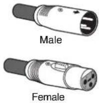
XLR connectors
This 3-pin connector is resistant to externally induced noise, and is used primarily for balanced connections. With properly designed receiving circuitry cables with this type of connector can also be used for unbalanced signals. XLR type connectors are the standard for microphone connections as well as most professional audio gear.
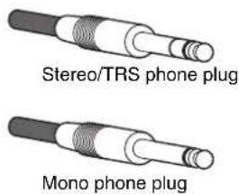
Phone jacks
Phone jacks are available in mono and stereo versions. Stereo types are also known as "TRS" connectors (Tip-Ring-Sleeve), and are used for stereo headphone jacks, insert jacks, and also to carry balanced signals in many cases. Unbalanced types are used for mono signals -guitar cables are a common example.
RCA Pin Connectors
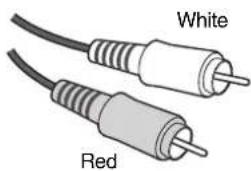
This type of unbalanced connector is most commonly found on home audio and video equipment. RCA type pin jacks are often color coded: white for left audio channel and red for right audio channel, for example.
natural_image
Two types of audio/video cables labeled 'White' and 'Red' (no additional text or symbols)Level Adjustment for Optimum Mix
Equalizer Tips
The best advice that can be given regarding equalization while recording is simply to use as little equalization as possible. If you want a little more presence you can turn the HIGH end up a bit. Or you can boost the bass a little if you feel the low end is lacking. During recording it's better to use EQ sparingly for compensation only.
- Cut for a Cleaner Mix
For example: pianos have a lot of energy in the mid and low frequency ranges that you don't really perceive as musical sound, but which can interfere with the clarity of other instruments in these ranges.
You can basically turn the low EQ on piano channels all the way down without changing the way they sound in the mix. You'll hear the difference, however, in the way the mix sounds more "spacious," and instruments in the lower ranges will have better definition.
Naturally you won't want to do this if the piano is playing solo. The reverse applies to kick drums and bass guitars: you can often roll off the high end to create more space in the mix without compromising the character of the instruments. You'll have to use your ears, though, because each instrument is different and sometimes you'll want the "snap" of a bass guitar, for example, to come through.
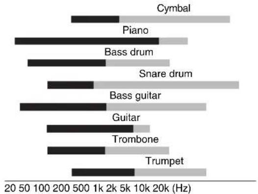
The fundamental and harmonic frequency ranges of some musical instruments.
bar
| Instrument | Frequency (Hz) | | :--- | :--- | | Cymbal | 1000 | | Piano | 2000 | | Bass drum | 5000 | | Snare drum | 1000 | | Bass guitar | 1000 | | Guitar | 1000 | | Trombone | 1000 | | Trumpet | 1000 |■ Fundamental: The frequency that determines the basic musical pitch.
■ Harmonics: Multiples of the fundamental frequency that play a role in determining the timbre of the instrument.
Comp settings
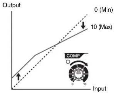
One form of compression known as "limiting" can, when properly used, produce a smooth, unified sound with no excessive peaks or distortion. A common example of the use of compression is to "tame" a vocal that has a wide dynamic range in order to tighten up the mix. Compression can also be applied to guitar tracks to add extra sustain. Too much compression can be a cause of feedback, however, so use it sparingly.
line
| Input | Output | |-------|--------| | 0 | 0 | | 10 | Max |Use the High-pass Filter for Microphone Input
As the name implies, a “high-pass filter” allows only signals above a certain frequency to pass. Conversely, signals below that “cutoff frequency” are attenuated. When an MGP high-pass filter is turned on, signals below 100Hz are attenuated.
This can be useful for minimizing low-frequency breath noise from a vocalist, as well as handling noise, or rumble transmitted via the microphone stand. It is generally a good idea to turn the high-pass filter on for microphone channels.
Start with the Featured Part
You can start working on a mix from almost any part, but it makes the most sense to start with the main instrument or vocal. Set up an initial level for the main part, and then build the rest of the mix around it.
For example, if you're mixing a piano trio with a vocalist, begin by setting the level of the vocal track at around the nominal level, and then gradually add the other instruments. Your choices will also be influenced by the type of music you are working on. If the song is a ballad you might want to add the piano to the mix after the vocal, and then add the bass and drums. If it's a more rhythmically oriented piece you could add the bass and drums first, and then the piano. Whatever best serves the music is right.
Setup Examples
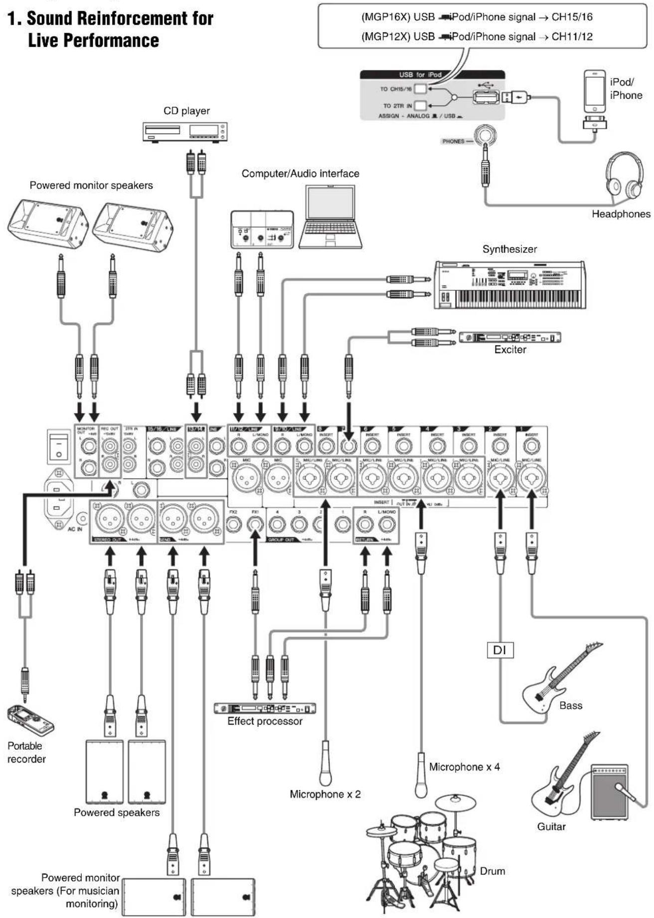
1. Sound Reinforcement for Live Performance
flowchart
graph TD
    A["CD player"] --> B["Powered monitor speakers"]
    A --> C["Computer/Audio interface"]
    A --> D["Synthesizer"]
    A --> E["Exciter"]
    A --> F["Portable recorder"]
    A --> G["Powered speakers"]
    A --> H["Powered monitor speakers (For musician monitoring)"]

    I["(MGP16X) USB"] --> J["USB for iPod"]
    K["(MGP12X) USB"] --> L["iPod/ iPhone signal → CH15/16"]
    K --> M["iPod/ iPhone signal → CH11/12"]

    N["PCB"] --> O["Effect processor"]
    P["DI"] --> Q["Bass"]
    R["Drum"] --> S["Guitar"]

    T["Microphone x 2"] --> U["Group OUT"]
    V["Microphone x 4"] --> W["L/MODIO"]

    X["AC IN"] --> Y["Radio OUT"]
    Z["FEI"] --> AA["Group OUT"]

    AB["AND Gate"] --> AC["Powered monitor speakers"]
    AD["LED System"] --> AE["Audio Interface"]
    AF["Handheld Device"] --> AG["Computer"]
- For Events and Parties
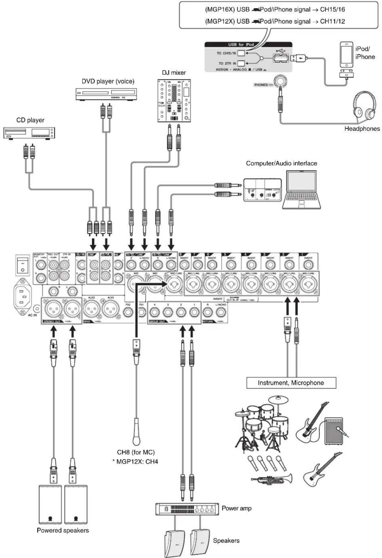
flowchart
graph TD
    A["CD player"] --> B["DVD player (voice)"]
    B --> C["DJ mixer"]
    C --> D["Computer/Audio interface"]
    D --> E["USB for iPod"]
    E --> F["iPod/ iPhone"]
    F --> G["Headphones"]
    G --> H["Instrument, Microphone"]
    H --> I["Power amp"]
    I --> J["Speakers"]
    B --> K["CH8 (for MC) * MGP12X: CH4"]
    K --> L["AUX2 AUX1 FX2"]
    L --> M["AC IN"]
    M --> N["+/-"]
    N --> O["Powered speakers"]
    style A fill:#f9f,stroke:#333
    style B fill:#ccf,stroke:#333
    style C fill:#cfc,stroke:#333
    style D fill:#fcc,stroke:#333
    style E fill:#ffc,stroke:#333
    style F fill:#fcc,stroke:#333
    style G fill:#fcc,stroke:#333
    style H fill:#fcc,stroke:#333
    style I fill:#fcc,stroke:#333
    style J fill:#fcc,stroke:#333
    style K fill:#cff,stroke:#333
    style L fill:#ffc,stroke:#333
    style M fill:#ffc,stroke:#333
    style N fill:#ffc,stroke:#333
    style O fill:#ffc,stroke:#333
Rack Mounting
The unit requires at least 11U* of rack space. To take into account the cable connections, we recommend to ensure at least 13U* of rack space.
* 11U corresponds to about 489mm and 13U is about 578mm.
■ Precautions for Rack Mounting
This unit is rated for operation at ambient temperatures ranging from 0 to 40 degrees Celsius. If you install this unit along with other devices in a poorly ventilated rack, the ambient temperature inside the rack may rise, resulting in inefficient performance. Be sure to rack-mount in the following conditions so the unit does not overheat.
- When mounting the unit in a rack with devices such as power amplifiers that generate a significant amount of heat, leave more than 1U of space between the MGP and other equipment. Also either leave the open spaces uncovered or install appropriate ventilating panels to minimize the possibility of heat buildup.
- To ensure sufficient airflow, leave the rear of the rack open and position it at least 10 centimeters from walls or other surfaces. If the rear of the rack cannot be left open, install a commercially available fan or similar ventilating option to secure sufficient airflow. If you've installed a fan kit, there may be cases in which closing the rear of the rack will produce a greater cooling effect. Refer to the rack and/or fan unit manual for details.
■ Mounting the MGP16X/MGP12X
- Two metal rack-mount brackets are screwed onto the unit. Use a screwdriver to remove these brackets.
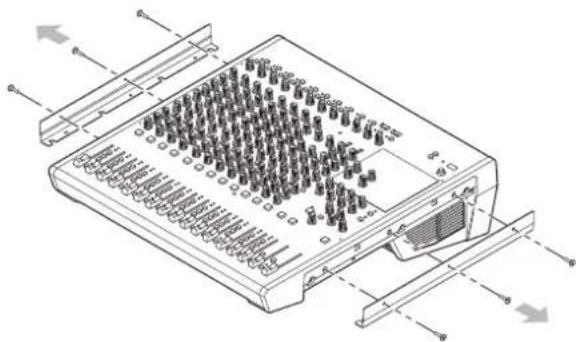
natural_image
Technical line drawing of an electronic device with multiple ports and connectors (no text or symbols)- Turn the brackets over, and fasten them into place again using the same screws.
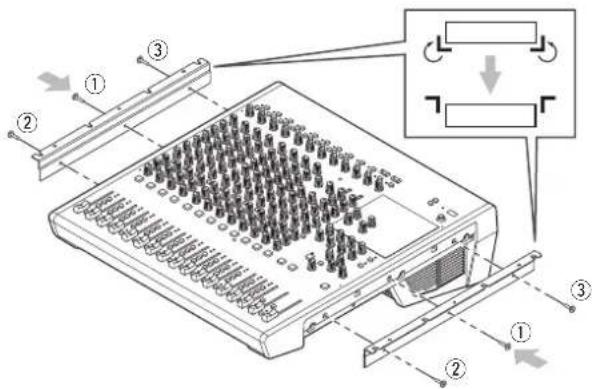
Fasten them to the mixer in order (as shown): ① center, ② front, and ③ back.
CAUTION
Be sure to use the same screws that were removed in step 1. Using other screws can cause damage.
MGP16X
- Mount the unit into the rack, and fasten it into place.
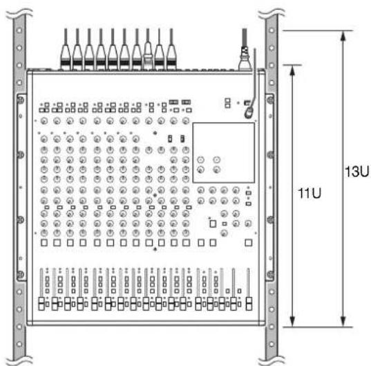
MGP12X
- Prepare the included rack-mount kit (2 supports and 6 screws).
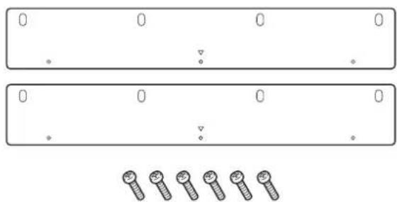
natural_image
Two identical rectangular panels with evenly spaced screw holes and a row of six screws below (no text or symbols)- Use the included screws to fasten the rack-mount supports with a triangular mark ( ) on the top side, to the installed rack-mount brackets in step 2.
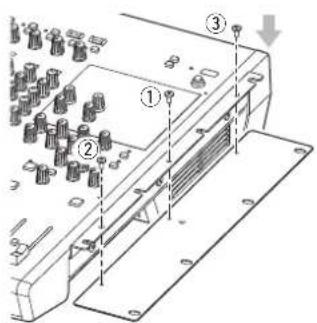
Fasten them to the mixer in order (as shown): ① center, ② front, and ③ back. Similarly fasten the other side as well.
CAUTION
Be sure to use the included screws with the MGP12X. Using other screws can cause damage.
- Mount the unit into the rack, and fasten it into place.
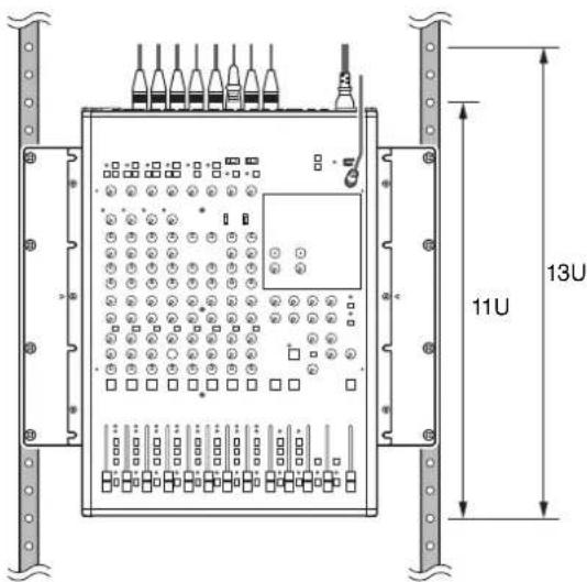
Security Cover Mounting
In order to prevent the control knobs of the front panel from being operated inadvertently, you can attach a protective cover using four screw holes on the unit. (Size: M3; horizontal spacing: 410mm for MGP16X and 311mm for MGP12X; vertical spacing: 208.5mm.) Yamaha does not sell such a cover; however, you can easily make one yourself and attach it to the front cover. When mounting a cover make sure that the screws used do not go deeper than 12 millimeters into the front panel. Also, to ensure that the cover does not come in contact with the panel controls, leave a space of about 20–25 millimeters between the front panel and the cover.
We'll begin this guide by connecting a pair of speakers and generating some stereo output. Note that the operations and procedures will vary somewhat according to the input devices you are using.
Step 1 Preparing the Power Supply
- Make sure that the power switch of the unit is set to the “Oposition (off).
- Connect the socket of the included power cord to the [AC IN] connector.
- Plug the power cord into a power outlet.
Step 2 Connections
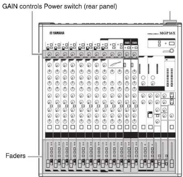
- Turn all the faders and gain controls completely down.
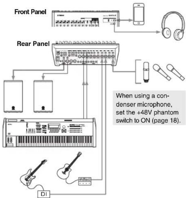
2. Connect the microphones and/or instruments you intend to use.
For details on making connections, refer to the "Setup Examples" on pages 8, 9.
flowchart
graph TD
    A["Front Panel"] --> B["Mobile Phone"]
    B --> C["Headphones"]
    D["Rear Panel"] --> E["Conductor"]
    D --> F["Handheld Mouse"]
    D --> G["CDI"]
    H["When using a condenser microphone, set the +48V phantom switch to ON (page 18)."] --> I["Handheld Mouse"]
Although electric guitars and basses can be connected directly to the mixer's inputs, the sound is likely to be thin and possibly noisy. For best results with these types of instruments use a DI box (direct box) or amp simulator between the instrument and the mixer.
Step 3 Powering Up the System
To prevent an unwanted burst of noise from the speakers, power up the devices in the following order: peripheral devices (instrument, microphone, iPod) → MGP mixer → power amps (or powered speakers).
Reverse this order when turning the power off.
CAUTION
- If you are using condenser microphones that require phantom power, turn the mixer's +48V switch on before turning on the power to the power amps or powered speakers. See page 18 for details.
- Be sure to turn the power on/off in the order given in Step 3 above every time you use the device. Failure to do so may result in loud noise bursts that can damage your equipment, your ears, or both.
Step 4 Getting Sound to the Speakers
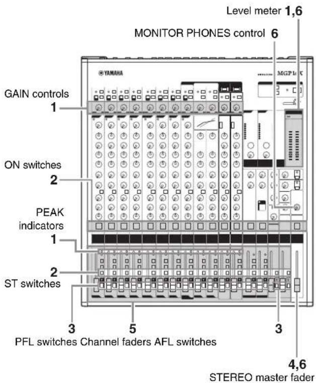
- Adjust the channel GAIN controls so that the corresponding peak indicators flash briefly on the highest peak levels.
NOTE
To use the level meter to get an accurate reading of the incoming signal level, turn the channel PFL switch on. Adjust the GAIN controls so that level meter indication occasionally rises above the “◀” (0) level.
Note that the PHONES jack outputs the pre-fader signal from all channels for which the PFL switch is ON, so that those signals can be monitored via the headphones.
- Turn on the ON and ST switches for each channel you are using.
- Make sure that all PFL and AFL switches are set to off ( )
- Raise the STEREO master fader to the "0" position.
- Set the channel faders to create the desired initial balance.
- Adjust the overall volume of the STEREO master fader.
The overall headphone level is adjusted by the MONITOR/PHONES control.
NOTE
If the PEAK indicator lights frequently, slightly lower the channel faders to avoid distortion.
Step 5 Using the Built-in Digital Effects
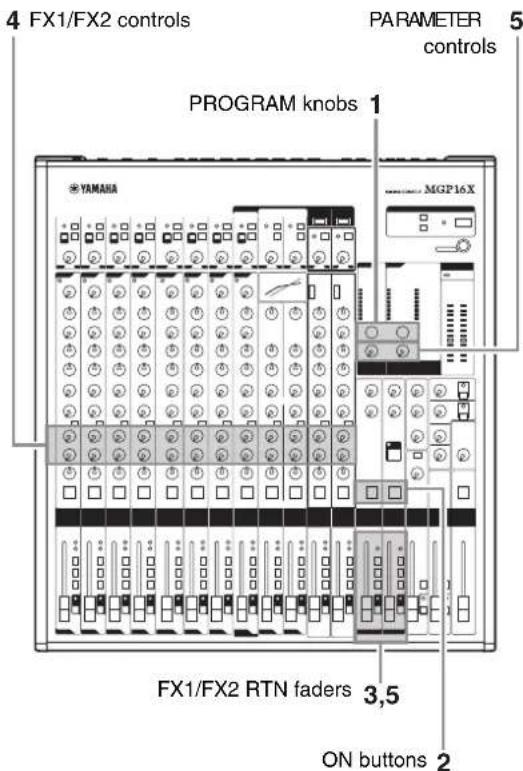
- Turn the PROGRAM knob to select the desired effect type.
To select a reverb effect, use the knobs, and set FX1 to any program, or FX2 to one of the programs 1 to 5.
- Turn on (the FX1/FX2 ON button.
The button lights up when it is turned on.
- Set the FX1/FX2 RTN fader to the "0" position.
- Use the channel FX1/FX2 knobs to adjust the effect depth for each channel.
- Use the FX1/FX2 RTN fader to adjust the overall effect depth.
Note that you can use the PARAMETER knob to adjust the sound characteristics of the selected effect. If you have selected a reverb effect, the knob adjusts the reverb time.
■ Built-in digital effects
Your mixes can be further refined by adding ambience effects such as reverb or delay.
The MGP's internal effects can be used to add reverb or delay to individual channels in the same way as external effects processors.
Reverb and Delay Time
Small adjustments to the reverb/delay time can actually have a significant effect on the sound. The optimum reverb time for a piece of music will depend on the music's tempo and density, but as a general rule longer reverb times are good for ballads, while shorter reverb times are more suited to up-tempo tunes. Delay times can be adjusted to create a wide variety of "grooves." When adding delay to a vocal, for example, try setting the delay time to dotted eighth notes ( ) corresponding to the tune's tempo.
Reverb Tone
Different reverb programs will have different "reverb tone" due to differences in the reverb time of the high or low frequencies. Too much reverb, particularly in the high frequencies, can result in unnatural sound and interfere with the high frequencies in other parts of the mix. It's always a good idea to choose a reverb program that gives you the depth you want without detracting from the clarity of the mix.
Reverb Level
It's amazing how quickly your ears can lose perspective and fool you into believing that a totally washed-out mix sounds perfectly fine. To avoid falling into this trap start with reverb level all the way down, then gradually bring the reverb into the mix until you can just hear the difference. Any more than this normally becomes a "special effect."
You don't want reverb to dominate the mix unless you are trying to create the effect of a band in a cave-which is a perfectly legitimate creative goal if that's the sort of thing you're aiming for.
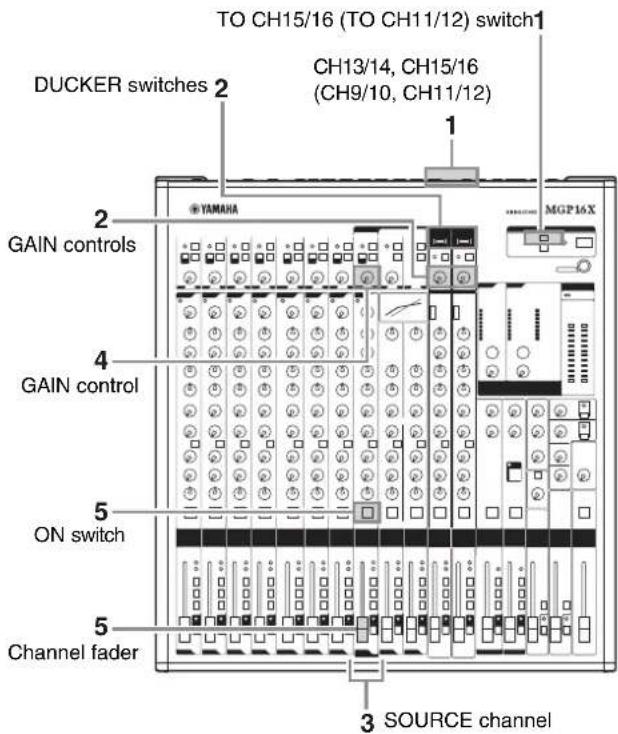
Step 6 Using the Ducker function
- Connect a music player or device for playing background music.
Connect the device to CH13/14 or CH15/16 on the MGP16X, and to CH9/10 or CH11/12 on the MGP12X.
To connect an iPod/iPhone, use the USB terminal of the MGP, and then set to the TO CH15/16 (TO CH11/12) switch to USB ( )
-
Turn on () the DUCKER switch for each channel you are using, and then adjust the channel's input to an appropriate level.
-
Connect the microphone to the SOURCE channel (MGP16X: CH8, MGP12X: CH4).
-
Adjust the input of the microphone to an appropriate level.
-
Turn on () the ON switch of the SOURCE channel, and then raise the channel fader to around "0" (nominal).
-
Play the background music, and listen to confirm that the sound volume automatically turns down when you speak into the microphone.
NOTE
- The volume on the SOURCE channel is detected after fader adjustment. It is affected by the setting of ON switch and/or the channel fader.
- If you want to make custom changes to the automatic sound attenuation, refer to "About the Detailed Setting Mode" on page 21.
Front Panel
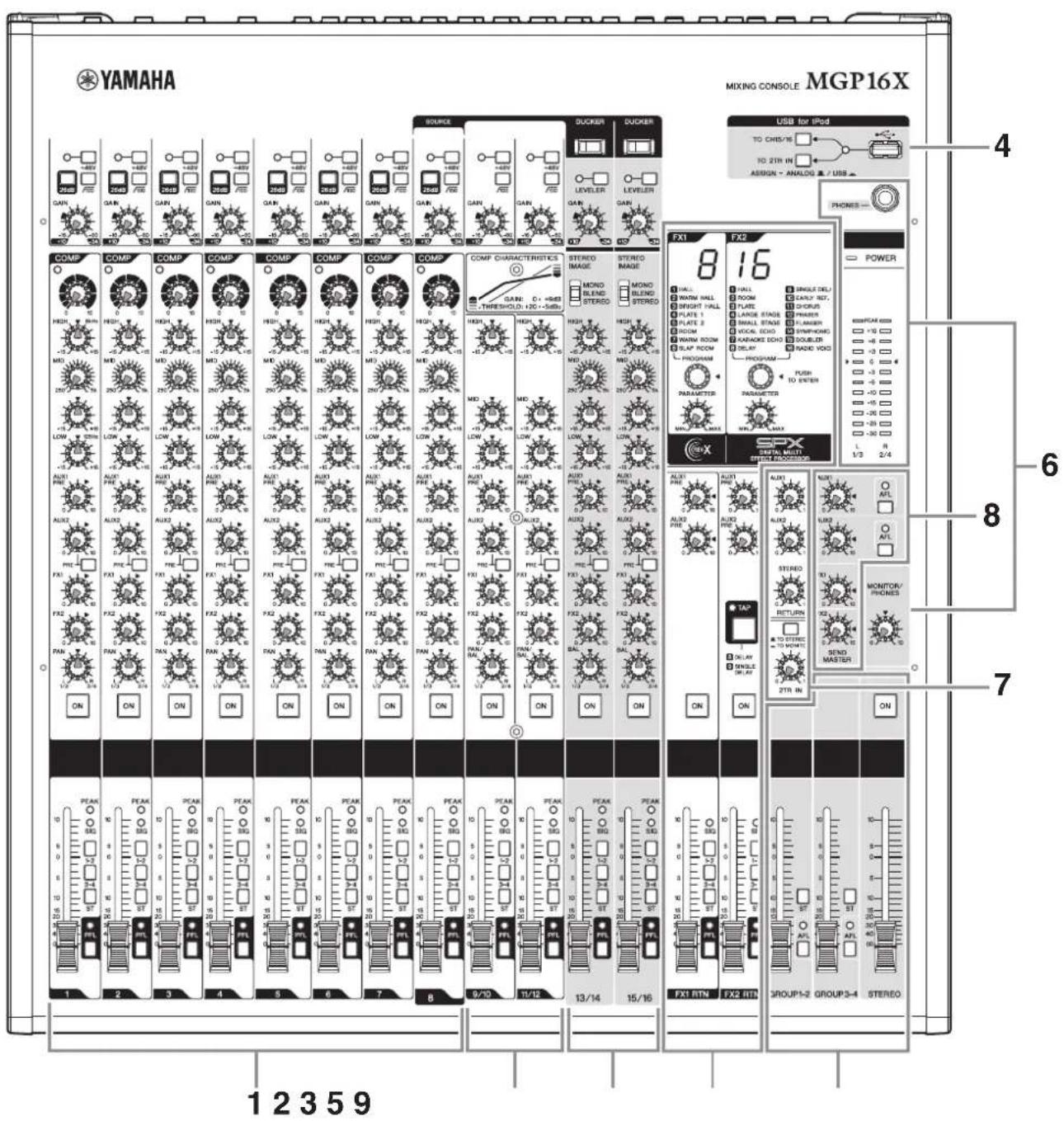
* Throughout this manual, all panel illustrations show the panel of the MGP16X. On the MGP12X, there are four channels in the mono input section (see 1 below) and 12 channels in the channel I/O connectors section (see 10 on the next page).
Channel Control Block
- Mono input section ...... page 18
- Mono and stereo input section ...... page 18
- Stereo input section...... page 18
Master Control Block
- iPod/iPhone section...... page 20
- Built-in digital effects section ...... page 21
- Meter/PHONES section...... page 23
- RETURN/2TR IN section...... page 23
- SEND MASTER section...... page 24
- GROUP/STEREO section ...... page 24
Rear Panel
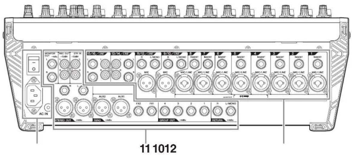
Rear Input/Output Block
- Channel I/O connectors section ...... page 25
- Master I/O connectors section...... page 26
- Power section...... page 26
Where Your Signal Goes Once It's Inside the Box
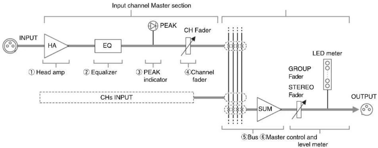
The purpose of configuring an audio system around a mixer is to collect signals from all channels and mix their levels and other settings to achieve a good balance. The following simplified mixer block diagram shows how the input signal flows once it's inside the mixer. For an overall block diagram of the MGP, see page 33.
Simplified Mixer Block Diagram
flowchart
graph LR
    A["INPUT"] --> B["HA"]
    B --> C["EQ"]
    C --> D["PEAK"]
    D --> E["CH Fader"]
    E --> F["SUM"]
    F --> G["LED meter"]
    G --> H["OUTPUT"]

    subgraph CHS INPUT
        I["① Head amp"] --> B
    end

    subgraph CHS INPUT
        J["② Equalizer"] --> C
        K["③ PEAK indicator"] --> D
        L["④ Channel fader"] --> E
    end

    subgraph SUM
        M["⑤ Bus"] --> N["STEREO Fader"]
    end

    subgraph OUTPUT
        O["GROUP Fader"] --> G
    end

    style CHS INPUT fill:#f9f,stroke:#333
    style SUM fill:#ccf,stroke:#333
    style LED meter fill:#cfc,stroke:#333
■ Input channel
①Head amp
The very first stage in any mixer, and usually the only stage with significant “gain” or “amplification.” The head amp has a “gain” control that adjusts the mixer’s input sensitivity to match the level of the source. Small signals (e.g. mics) are amplified, and large signals are attenuated.
②Equalizer
An equalizer boosts (amplifies) or cuts (attenuates) certain frequency ranges to shape the tone. It can be used to modify the tone to suit the acoustic characteristics of a room, to make creative sounds, or for many other purposes. An equalizer could be a high pass filter that cuts the sound below a specified frequency.
③PEAK indicator
When the level of an input signal exceeds the level that can be handled by the mixer's head amp or equalizer, distortion and noise will result. The PEAK indicators are used to visually check the signal level to ensure no overload occurs.
If the PEAK indicator lights continuously, make sure that signals are not amplified too much by the equalizer, and if needed, adjust the GAIN control of the head amp to reduce the level.
It is important to know the mixer stage for which the PEAK indicators are indicating signal levels. The PEAK indicator of this unit detects the signal after the head amp and EQ stage.
④Channel fader
A channel fader enables you to adjust the level of the corresponding input channel signal that is going to be routed to the buses (excluding a pre-fader signal). It is the most often used control during performance.
■ Master section
⑤Bus (Summing Amplifier)
This is where the actual “mixing” takes place. Signals from all of the mixer’s input channels are “summed” (mixed) together here.
The signals flow in each channel from top to down after being adjusted by the level control, and then these signals are summed (mixed) from left to right. Finally, the overall level is adjusted by the master control located at far right.
The operation of summing from left to right is the role of the bus (summing amplifier).
⑥Master control and level meter
The master controls, specifically, the STEREO fader and GROUP faders, are the means used to adjust the level of all signals from all of the mixer's input channels. The level meter LED shows the level of the signal flowing to the STEREO bus.
Channel Control Block
Mono input section Mono and stereo input section Stereo input section
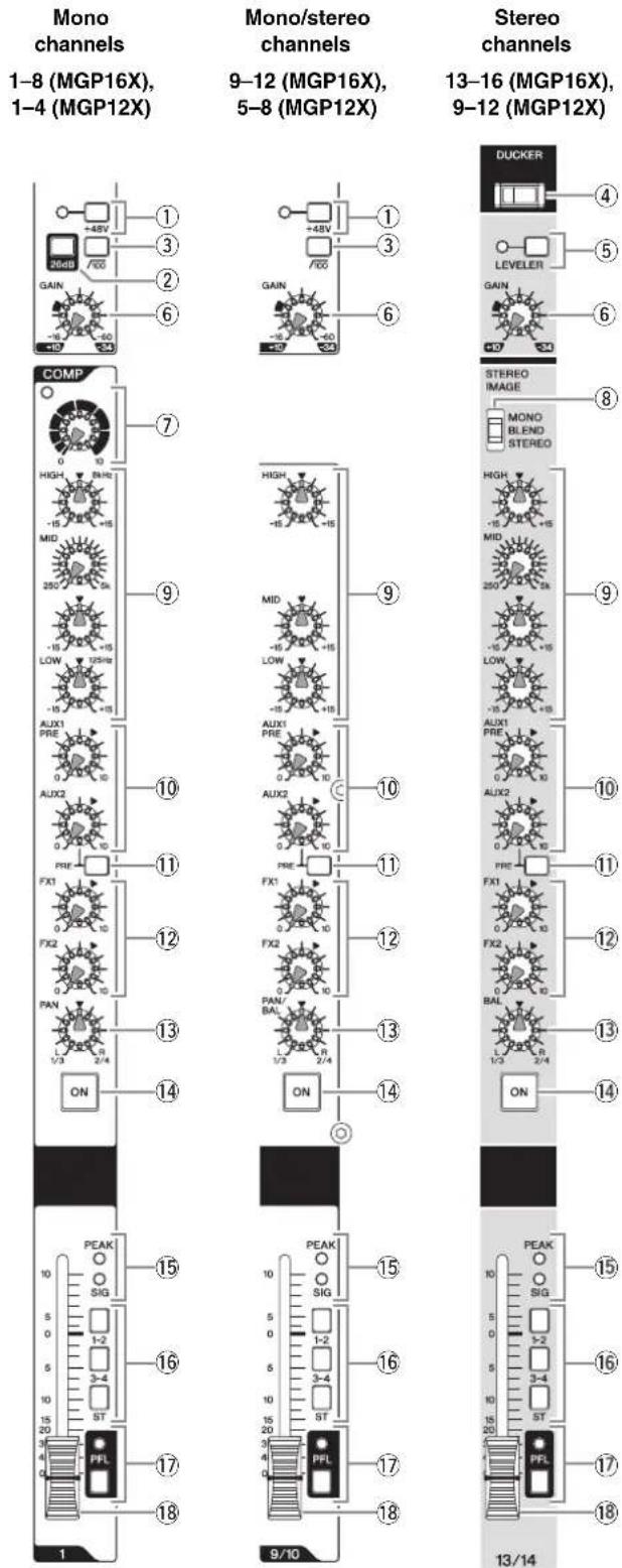
1-8 (MGP16X), 1-4 (MGP12X)
9–12 (MGP16X), 5–8 (MGP12X)
13–16 (MGP16X), 9–12 (MGP12X)
①+48V switch and indicator
This switch toggles phantom power on and off. When this switch is turned on ( ) the mixer supplies DC +48V power to pins 2 and 3 of all XLR input jacks. Turn this switch on when using one or more phantom-powered condenser microphones. The indicator lights when it is turned on.
CAUTION
- Be sure to leave this switch off ( )■you do not need phantom power. Humming or damage may result if you connect to an unbalanced device or to an ungrounded transformer while this switch is on.
- When turning the switch on, make sure that only a condenser microphone is connected to the XLR input jacks. Devices other than condenser microphones may be damaged if connected to the phantom power supply. This precaution does not apply to balanced dynamic microphones, however, as these will not be affected by phantom power.
- To prevent damage to speakers, be sure to turn off power amplifiers (or powered speakers) before turning this switch on or off. It's also a good idea to turn the mixers output controls - the STEREO master and GROUP (1-2, 3-4) faders - all the way down when turning phantom power on. Neglect of these precautions may result in large noise bursts that may damage your equipment, your ears, or both.
②26dB (PAD) switch
When this switch is turned on ( ), the input signal from the MIC/LINE jack of the mono channel is attenuated by 26dB.
Turn this switch off (If you've connected a microphone or other device with a low input level to the channel. Turn it on (If you've connected a line-level device.
③ (High Pass Filter) switch
Turning this switch on ( ) will apply a high-pass filter that attenuates frequencies below 100Hz in the signal by a slope of 12dB/octave.
④DUCKER switch
When this switch is turned on ( ) the volume of the stereo channels is automatically lowered when a signal exceeding a certain level is input to the SOURCE channel (MGP16X: CH8, MGP12X: CH4). You can use this switch, for example, when you want to have the volume of background music automatically lowered when making an announcement on the microphone. For effective use of this switch, see Step 6 on page 14. The switch lights when it is turned on.
NOTE
You can adjust the attenuation of the Ducker function in the detailed setting mode (see column on page 21).
⑤LEVELER switch and indicator
When playing music from an iPod/iPhone or other audio players, the actual sound output level may differ for each song depending on the assigned category. Turning this switch on ()lets you have the volume adjusted automatically to a certain level, preventing sudden jumps or dips in the level. The indicator lights when it is turned on.
NOTE
If an audio player other than iPod/iPhone is connected to the input jacks (LINE) on the rear panel, initially adjust the input level according to the softest part (lowest level) of the song, and then turn on the LEVELER switch. Adjust the input level so that the level meter indication occasionally rises above the “◀” (0) level while the PFL switch is on.
⑥GAIN control
Adjusts the sensitivity of the input signal. Monaural channels have a 26dB switch (②) that lets you change the range of this control. The adjustable sensitivity range is as follows.
Mono channel
| 26dB switch Range | |
| ON-34dB to +10dB | |
| OFF -60dB to -16dB |
Stereo channel
-34dB to +10dB
⑦COMP control and indicator
Adjusts the amount of compression applied to the channel. As the knob is turned to the right the compression ratio increases while the output gain is automatically adjusted accordingly. The result is smoother, more even dynamics because louder signals are attenuated while the overall level is boosted. The COMP indicator will light when the compressor operates.
NOTE
Avoid setting the compression too high, as the higher average output level that results may lead to feedback.
⑧STEREO IMAGE switch
This switch selects the output signal by switching the input stereo signal to one of the following three signal types.
- MONO : Mono signal
- BLEND: Stereo signal in which left and right inputs are mixed in a certain percentage for a more natural stereo image.
• STEREO : Stereo signal (original, as is)
⑨Equalizer (HIGH, MID, and LOW)
This three-band equalizer adjusts the channel's high, mid, and low frequency bands.
Setting the knob to the “▼” position produces a flat response in the corresponding band. Turning the knob to the right boosts the corresponding frequency band, while turning to the left attenuates the band. The upper knob sets the center frequency for the mid range, while the lower knob sets the amount of attenuation or boost (counterclockwise/clockwise) for the range. For the CH9/10 and CH11/12 (on the MGP16X), and CH5/6 and CH7/8 (on the MGP12X), the attenuation/boost can only be set at a fixed 2.5kHz center frequency.
The following table shows the EQ type, frequency, and cut/boost range for each of the three bands.
| Band Type Frequency | Cut/Boost range | ||
| HIGH Shelving 8kHz | ±15dBMD | ||
| LOW | Shelving 125Hz | ||
Peaking 2.5kF
* The MID frequency can be adjusted from 250Hz to 5kHz. The MID frequency is 2.5kHz when the MID frequency control is set at the center position.
⑩AUX1 PRE, AUX2 controls
These knobs adjust the channel's signal levels sent to AUX buses 1 and 2. Each knob controls the signal sent to the corresponding AUX bus. These knobs should generally be set close to the “▼” (nominal) position. The AUX1 control adjusts the signal before the channel fader (pre-fader). The signal adjusted by the AUX2 control is determined by the PRE switch (⑪).
⑪PRE switch
This switch selects whether the signal sent to the AUX 2 bus is taken after the equalizer but before the channel fader (prefader), or after the channel fader (post-fader). When the switch is on () the mixer sends the pre-fader signal to the AUX2 bus, so that the AUX2 output is not affected by the fader.
⑫FX1, FX2 controls
Adjusts the level of the signal (post-fader) sent from the channel into the FX bus. These knobs should generally be set close to the “▼” position.
NOTE
- To send the signal to the bus engage the ON switch (14).
- On stereo channels, the LINE L (odd) and LINE R (even) input signals are mixed before moving into the bus.
⑬PAN control
PAN/BAL control
BAL control
The PAN control knob determines the stereo positioning of each mono channel signal in the GROUP 1-2, 3-4 buses or in the stereo L and R buses. For example, rotating the knob toward L moves the sound to the left (depending on the location of the knob).
The BAL control knob sets the balance between left and right stereo channels. For example, rotate the knob toward L to increase the volume level of the left or Groups 1 and 3, and decrease the level of the right or Groups 2 and 4.
⑭ON switch
Turn this switch on ( ) to send the respective channel's signal to the buses. The switch lights when on.
⑮Input Meter
The LEDs indicate the input channel's post-equalizer signal level. The SIG indicator lights when a signal is being input into the channel. The PEAK indicator lights when the input signal level is 3dB below clipping.
⑯Bus assign switches
These switches determine the bus(es) to which each channel's signal is sent. Press the switch in ( ) to output the signal to the corresponding buses.
- 1-2, 3-4 switches: Assign the channel's signal to the GROUP1-2, 3-4 buses.
- ST switch: Assigns the channel's signal to the STE-REO L and R buses.
NOTE
To send the signal to each bus, engage the ON switch.
⑰PFL switch and indicator
When the PFL (Pre-Fader Listen) switch is on (), the indicator will light and the channel pre-fader signal is output to the MONITOR OUT and PHONES jacks for monitoring.
⑱Channel fader
Adjusts the level of the channel signal. Use these controls to adjust the balance between the various channels.
NOTE
To reduce noise, set the fader sliders for any unused channels all the way down.
Master Control Block
iPod/iPhone section
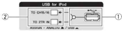
flowchart
graph LR
    A["②"] --> B["USB for iPod"]
    B --> C["TO CH15/16"]
    B --> D["TO 2TR IN"]
    C --> E["Device Icon"]
    D --> E
    E --> F["①"]
①USB connector and indicator
This is a USB port dedicated for iPod/iPhone use. Using the USB cable that came with the iPod/iPhone, connect the iPod/iPhone. The indicator lights when the mixer recognizes the iPod/iPhone.
If the mixer does not recognize the device or if a non-compliant iPod/iPhone is connected, the indicator remains off.
For details on supported iPod/iPhone models, see “Supported iPod/iPhone models” on page 30.
CAUTION
- Use the genuine Apple Dock Connector USB Cable for the iPod/iPhone connection.
- Connect the USB connector to the iPod/iPhone before turning the mixer power on.
- When connecting to an iPod/iPhone, allow at least 6 seconds to pass between turning the mixer on and off and plugging or unplugging the USB cable.
- Please do not use a USB hub.
- The mixer's USB port is dedicated for iPod/iPhone use only. Please do not connect other USB devices.
NOTE
- While the indicator lights, the iPod/iPhone is charged.
- If you connect your iPhone, an incoming call cause a ringing sound to be output. In order to prevent this, we recommend that your iPhone's "Airplane" mode be turned on.
②Routing assign switches
Determine the destination of the input signal. The switch setting and the destination is shown below.
| Switch | Switch Setting | Audio Signal Input Source | Output Destination Channels |
| TO CH15/16 (MGP16X)TO CH11/12 (MGP12X) | ANALOG | CH15/16 jacks (MGP16X)CH11/12 jacks (MGP12X) | CH15/16 (MGP16X)Ch11/12 (MGP12X) |
| USB | iPod/iPhone | ||
| TO 2TR IN | ANALOG | 2TR IN jacks | 2TR IN |
| USB | iPod/iPhone |
NOTE
- The volume of an iPod/iPhone which was assigned to CH15/16 (CH11/12) cannot be controlled by the GAIN control.
- Use the detailed setting mode in the column on the next page to attenuate the playback level from an iPod/iPhone assigned to CH15/16 (CH11/12).
■ About the Detailed Setting Mode
The detailed setting mode lets you adjust the attenuation of the CH15/16 (CH11/12) for adjusting the play level from the iPod/iPhone, and also adjust the range of the Ducker function.
Procedure
- Press both FX1 and FX2 PROGRAM knobs simultaneously for at least two (2) seconds.
- "P" flashes on the FX1 LED display and "R" or "D" lights on the FX2 LED display.
The mixer enters the detailed setting mode. The available detailed setting parameters, LED display, and range are as follows.
| Parameter LED | display Range | |
| CH15/16 (CH11/12)Attenuation(Attenuator) | -24dB – 0dB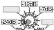 | |
| Ducker Attenuation(Ducker Range) | -70dB – 0dB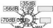 |
* The Ducker attenuation range is common for CH13/14 and CH15/16 (MGP12X: CH9/10 and CH11/12).
- Use the PROGRAM knob to select the parameter ("R" or "o'") you want to change.
- Use the FX2 PARAMETER control to adjust the attenuation.
Please refer to the above table for the range.
- Press the PROGRAM knob again.
The mixer saves the settings, and then exits the detailed setting mode.
NOTE
- The mixer retains the last setting made, even after the power is turned off.
- To restore the default settings, press the TAP button while in the condition of step 3 above.
- When the parameter setting is different from the default setting (i.e., when you've changed the parameter value from the default), a dot indication is displayed at the lower right of the FX2 program number.
Built-in digital effects section
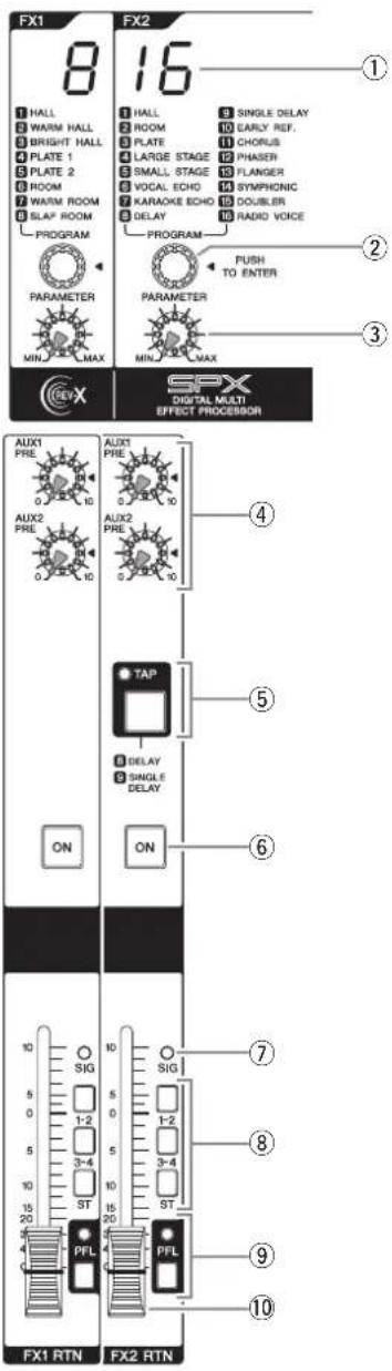
①Effect program display
Displays the program number selected with the PROGRAM knob (②).
②PROGRAM knob
Selects one of 8 internal effects from FX1 and 16 internal effects from FX2. Turn the knob to select the desired effect, and then press the knob to enable it.
See page 28 for details about the internal effects.
NOTE
You can also select the desired effect by turning the knob while holding it down.
③PARAMETER control
Adjusts the parameter (depth, speed, etc.) for the selected effect. The last value used with each effect type is saved.
NOTE
When you change to a different effect type, the mixer automatically restores the value that was previously used with the newly selected effect (regardless of the current position of the PARAMETER Control knob).
④ AUX PRE controls (1, 2)
Each knob adjusts the level of the effect-processed sound sent to the corresponding AUX1 and AUX2 buses.
⑤TAP button and indicator
This feature lets you set the delay time (tempo) for FX2 by tapping on the button. The feature only works when the effect type for FX2 is set to 8 DELAY or 9 SINGLE DELAY.
To set the tempo, tap on the button at the appropriate interval. The average interval (BPM) at which you tap the button will be calculated, and that value will be set for the tempo. Continue tapping as necessary until you get the timing right.
The average interval will be set (the average of a, b, and c)
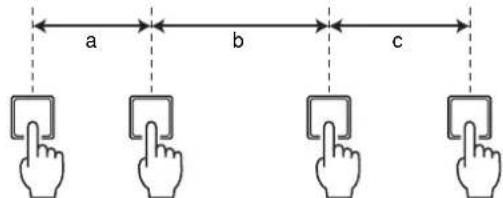
First tap Second tap Third tap Fourth tap
The TAP indicator flashes in sync with the tempo when the 8 DELAY or 9 SINGLE DELAY is selected.
NOTE
- The tempo is not set when the average interval at which you tap the button is out of the range of 80 – 300BPM.
- For more information on the tempo range, see page 28.
- The mixer retains the last tempo setting made, even after the power is turned off.
⑥ON button
This button turns the corresponding internal digital effect on or off. When the function is on, the button lights.
NOTE
The On/Off status of the internal effects will be retained, even when you turn off the power.
⑦SIG indicator
Lights when an effect signal is input into the channel.
⑧Bus assign switches
These switches determine the bus(es) to which the signal of the internal digital effects is sent. Press the switch in (→to output the signal to the corresponding buses.
• 1-2, 3-4 switches: Assign to the GROUP 1-2, 3-4 buses.
- ST switch: Assigns to the STEREO L/R bus.
⑨PFL switch and indicator
When the PFL (Pre-Fader Listen) switch is on (), the indicator will light and the pre-FX (1, 2) RTN-fader signal is output to the MONITOR OUT and PHONES jacks for monitoring.
NOTE
If both PFL and AFL switches are turned on, only the PFL switch is enabled. To monitor the post-fader signal, make sure to turn off all PFL switches.
⑩FX RTN faders (FX1, FX2)
These adjust the level of the effect sent from the internal effect to the GROUP 1-2, 3-4 and STEREO L/R buses.
To restore the initial factory settings for the internal effects, turn on the power while holding the TAP button (⑤) and the ON button (⑥).
Meter/PHONES section
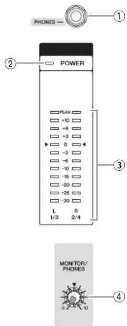
①PHONES jack
Connect a pair of headphones to this TRS phone jack. The PHONES jack outputs the same signal as the MONITOR OUT jacks.
②POWER indicator
This indicator lights up when the mixer's power is ON.
③Level meter
This LED meter displays the level of the signal output from the STEREO OUT jack, or the signal selected by the 2TR IN switch and PFL/AFL switch.
The "0" segment corresponds to the nominal output level. The PEAK segment lights when output reaches the clipping level.
NOTE
The PFL signal has display priority when an input channel's PFL switch is on ( ).
④MONITOR/PHONES control
Controls the level of the signal output to the PHONES jack and the MONITOR OUT jacks.
RETURN/2TR IN section
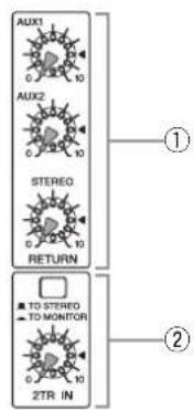
①RETURN
- AUX1, AUX2 controls: Adjust the level at which the L/R signal received at the RETURN jacks (L (MONO) and R) is sent to the AUX1 and AUX2 buses.
- STEREO control: Adjusts the level at which the signal received at the RETURN jacks (L (MONO) and R) is sent to the STEREO L/R bus.
NOTE
If you supply a signal to the RETURN L (MONO) jack only, the mixer sends the same signal to both the L and R Stereo buses.
②2TR IN
- 2TR IN switch: If this switch is set to TO MONITOR (), the signals input via the 2TR IN jacks or the iPod/iPhone are sent to the MONITOR OUT jacks, the PHONES jack, and the level meter. If it is set to TO STEREO ( ), the signals are sent to the STEREO L/R buses.
- 2TR IN control: Adjusts the level of the signal sent from the 2TR IN jacks or the iPod/iPhone to the STEREO L/R buses.
SEND MASTER section
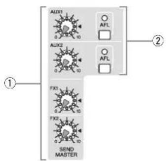
①SEND MASTER controls (AUX1, AUX2, FX1, FX2)
These adjust the signal level sent to the AUX, AUX2, FX1 and FX2 SEND jacks.
NOTE
These SEND MASTER controls do not affect the level of the signal sent from the internal digital effect to the FX1 and FX2 buses.
②AFL switch and indicator
When the AFL (After-Fader Listen) switch is on, the indicator lights and the signal after the AUX1 and AUX2 controls (①) adjustment is output to the MONITOR OUT and PHONES jacks for monitoring.
NOTE
- The PFL signal has priority when both the PFL switch and AFL switch are on. To monitor the post-fader signal, make sure to turn off all PFL switches.
- If the PFL (preferred) is enabled, the AFL indicator does not light, even if the AFL switch is pressed.
GROUP/STEREO section
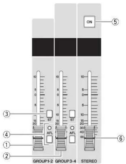
①GROUP 1-2 fader
Adjusts the signal level to the GROUP OUT 1 and GROUP OUT 2 jacks.
②GROUP 3-4 fader
Adjusts the signal level to the GROUP OUT 3 and GROUP OUT 4 jacks.
③ST switch
If this switch is on, the signals are sent to the STEREO L/R bus via the GROUP1-2 or 3-4 fader. The Group 1 and 3 signal goes to Stereo L and the Group 2 and 4 signal goes to Stereo R.
④AFL switch and indicator
When the AFL (After-Fader Listen) switch is on, the indicator lights and the signal after GROUP 1-2 (①) or 3-4 (②) faders adjustment is output to the MONITOR OUT and PHONES jacks for monitoring.
NOTE
- The PFL switch has priority when both the PFL switch and AFL switch are on. To monitor the post-fader signal, make sure to turn off all PFL switches.
- If the PFL is enabled (preferred), the AFL indicator does not light, even if the AFL switch is pressed.
⑤ON switch
Turn this switch on to enable the STEREO master fader. The switch lights when on.
⑥STEREO master fader
Adjusts the signal level sent to the STEREO OUT jacks.
Rear Input/Output Block
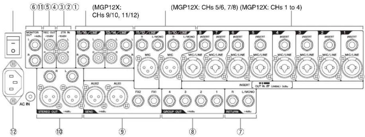
Channel I/O connectors section
①Mono inputs
- INSERT: These jacks are located between the compressor and equalizer of the corresponding input channel. The INSERT jacks are ideal for connecting devices such as graphic equalizers or noise filters into the corresponding channels. These are TRS (tip, ring, sleeve) phone jacks that carry both the send and return signal (tip = send/out; ring = return/in; sleeve = ground).
NOTE
Connection to an INSERT I/O jack requires a special insertion cable as illustrated below. Use a separately-sold Yamaha insertion cable (YIC025/050/070).
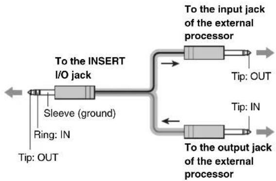
flowchart
graph LR
    A["To the INSERT I/O jack"] --> B["Sleeve (ground)"]
    B --> C["Ring: IN"]
    C --> D["Tip: OUT"]
    A --> E["To the input jack of the external processor"]
    E --> F["Tip: OUT"]
    A --> G["To the output jack of the external processor"]
    G --> H["Tip: IN"]
CAUTION
The signal output from the INSERT jacks is reverse-phased. This should not be a problem when connecting to an effect unit, but please be aware of the possibility of phase conflict when connecting to other types of device. A reversed-phased signal may result in degraded sound quality or even complete sound cancellation.
- MIC/LINE: These are combo jacks that support both XLR-type and TRS phone-type plugs, and are for connection of both microphones and/or instruments.
②Mono/Stereo inputs
• LINE: These are unbalanced phone-jack stereo line inputs.
- MIC: These are balanced XLR-type microphone input jacks. (1: Ground; 2: Hot; 3: Cold)
NOTE
On any given channel, you may use either an XLR or phone jack, but not both.
③Stereo input
• LINE: These are stereo input jacks that connect line-level instruments, such as a synthesizer. These are unbalanced input jacks. Two jack types are provided: phone type and RCA pin type.
NOTE
On any given channel, you may use either a phone or RCA jack, but not both.
Master I/O connectors section
④2TR IN
These RCA pin jacks can be used to input a stereo sound source. Use these jacks when you want to connect a CD player, and output the signal to the monitor or the STEREO L/R bus.
NOTE
You can adjust the signal level using the 2TR IN control in the Master Control block.
⑤REC OUT
These RCA pin jacks can be connected to an external recorder such as an MD recorder in order to record the same signal that is being output via the STEREO OUT jacks.
NOTE
The mixer's STEREO master fader has no affect on the signal output via these jacks. Be sure to make appropriate level adjustments at the recording device.
⑥MONITOR OUT
Connect these impedance-balanced* TRS phone jacks to your monitor system. These jacks output the signal before or after the faders for the various buses. The PFL and AFL indicators in each section indicate which signal is being output.
\* Impedance balanced
Since the hot and cold terminals of impedance balanced output jacks have the same impedance, these output jacks are less affected by induced noise.
NOTE
The PFL switch has priority when both the PFL switch and AFL switch are on. To monitor the post-fader signal, make sure to turn off all PFL switches.
⑦RETURN
These are unbalanced phone-jack type line input jacks. The signal received by these jacks is sent to the STEREO L/R buses and the AUX1 and AUX2 buses. The mixed signal of L (MONO) and R is sent to the AUX1 and AUX2 buses. These jacks are typically used to receive the signal returned from an external effect device (reverb, delay, etc.).
NOTE
• These jacks can also be used as an auxiliary stereo input.
- If you connect to the L (MONO) jack only, the mixer will recognize the signal as monaural and will send the identical signal to both the L and R jacks.
⑧GROUP OUT
These impedance-balanced* TRS phone jacks output the GROUP 1-2, 3-4 signals. Use these jacks to connect to the inputs of a multi-track recorder, external mixer, or another similar device.
⑨SEND
You use these jacks, for example, to connect to an effect device or monitor system.
- AUX1, AUX2: These are balanced XLR-3-32 type output jacks (1: Ground; 2: Hot; 3: Cold).
- FX1, FX2: These are impedance balanced* phone-jack type output jacks. These jacks output the signals from the FX1 and FX2 buses, respectively.
⑩STEREO OUT
These are XLR type and TRS phone type balanced output jacks that output the mixed stereo signal. The signal level is adjusted by the STEREO master fader before it is output. You can use these jacks, for example, to connect to the power amplifier driving your main speakers.
Power section
⑪POWER switch
Turns power to the unit ON or OFF. Press the switch to the “” position to turn on the power. Press the switch to the “” position to turn off the power.
CAUTION
Rapidly turning the unit ON and OFF in succession can cause it to malfunction. After turning the unit OFF, wait for about 6 seconds before turning it ON again.
⑫AC IN connector
Connect the included power cord here. First, connect the power cord to the MGP, and then plug it into an AC outlet.
| ■ Power doesn't come on. | □ Is an independent power-supply unit such as a power generator, or a power strip with switch plugged into the mixer?Make sure that the power is turned on. |
| ■ No sound. | □ Are microphones, external devices, and speakers connected correctly?□ Is a Y-shaped cable used to connect the INSERT connector or an external device?□ Are your cables connected properly, or are they shorted or faulty?□ Are the channel GAIN controls, channel faders, STEREO master fader and GROUP 1-2/3-4 faders set to appropriate levels?□ Are the bus assign switch and 2TR IN switch set properly?□ (When using STEREO OUT jacks) Are the ON switch and ST switch of the channels you are using turned ON?□ (When using STEREO OUT jacks) Is the ON switch of the STEREO master turned on?□ (When using AUX 1/2 and FX 1/2 jacks) Are the respective SEND MASTER control, AUX 1/2 and FX 1/2 controls of each channel set to appropriate levels?□ (When using MONITOR OUT jacks ) Are the PFL switches for the channels that you are not using turned on? Make sure to turn off the PFL switch.□ [For signals that are input to the 2TR IN and CH15/16 (CH11/12) jacks] Is the routing assign switch set to USB ( ) ▲ Make sure to set the switch to ANALOG ( ). ■ |
| ■ Sound is faint, distorted, or noisy. | □ Are the channel GAIN controls, channel faders, STEREO master fader and GROUP 1-2/3-4 faders set to appropriate levels?□ Is the 26dB switch turned on?Make sure to turn off the switch when a low-level source, such as a microphone, is input.□ Is the output signal from the connected device set to an appropriate level?□ Are you applying the effects and compressor at appropriate levels?You may have to lower the FX (1, 2) control, FX RTN fader, and COMP control levels.□ Are two different instruments connected to the XLR-type and phone jacks, or to the phone and RCA pin jacks on one channel?Make sure to connect to only one of these jacks on each channel.□ Are microphones connected to the MIC input jacks or MIC/LINE input jacks ?□ If you are using condenser microphones, is the +48V switch turned ON?□ If you are connecting a device which has a specified output level of +4dBu, turn on the 26dB (PAD) switch of the mono channels or use stereo channels.□ (Stereo channel) Is the DUCKER switch turned on?When a signal is constantly input to CH4 (MGP12X)/CH8 (MGP16X), the sound becomes faint. |
| ■ No effect is applied. | □ Check that the EFFECT knob on each channel is correctly adjusted.□ Check whether the ON button of FX1/FX2 is turned on or off.□ Be sure that the PARAMETER control and FX RTN fader are correctly adjusted.□ Check that the switch for the desired bus in the FX1/FX2 RTN bus assign switches is turned on.□ When an effect device is connected to the FX1 or FX2 jack, is the FX1 or FX2 control on the SEND MASTER set to appropriate levels? |
| ■ The FX1/FX2 ON buttons are not locked. | □ The FX1/FX2 ON buttons are of a type that do not lock. |
| ■ I want spoken words to be heard more clearly. | □ Make sure that the /100 switch is turned ON.□ Are the equalizers (HIGH, MID, and LOW knobs) on each channel adjusted appropriately? |
| ■ I want to output a monitor signal for the mixer through speakers. | □ Connect a powered speaker to the MONITOR OUT jack.Make sure to adjust the level of output signal from the MONITOR OUT jack with the MONITOR/PHONES control. |
| ■ The level meter doesn't show the output signal level. | □ Are the PFL switches for the channels you are not using turned on?Make sure to turn off the PFL switch. |
| ■ iPod/iPhone signal is not output. | □ Is the USB cable that came with Pod/iPhone properly connected to the mixer?□ Is the routing assign switch set to USB 📄?□ Is the LED indicator turned off?The mixer has not recognized your iPod/iPhone. Check which iPod/iPhone models are supported. |
| ■ The supported iPod/iPhone is not recognized. | □ If your iPod/iPhone has not been charged, it may take some time to be recognized by the mixer. Please wait. |
| ■ When a stereo signal is input, the left and right volume is different. | □ Is the pan control set to the center position?If it is located in the center, try swapping the connections. If the lesser/greater volume signals are also switched, check the connected device(s).□ Is the same type of cable used for the right and left signals?A cable with resistance lowers the volume. |
| ■ The sound level is inconsistent, or there is an unnatural “pumping” in the sound. | □ Are you applying the compressor at an appropriate level?You might have to lower the COMP control levels. |
| ■ The Leveler is not enabled. | □ Is the GAIN control on the stereo channels adjusted appropriately?The Leveler may not be enabled if you increase the gain too much. |
* If any specific problem should persist, please contact your Yamaha dealer.
Digital Effect Program List
■FX1 REV-X (REV-X algorithm)
| No. | Program | Parameter | Variable range | Description |
| 1 | HALL Reverb Time 0.3 | s – 10.0 s Reverb | simulating a large space such as a hall. | |
| 2 | WARM HALL Reverb Time | 0.3 s – 10.0 s | Warm reverb simulating a hall. | |
| 3 | BRIGHT HALL Reverb | Time 0.3 s – 10.0 s | Bright reverb simulating a hall. | |
| 4 | PLATE 1 Reverb Time | 0.3 s – 10.0 s | Reverb simulating a metal-plate. Suitable for vocals. | |
| 5 | PLATE 2 Reverb Time | 0.3 s – 10.0 s | Reverb simulating a metal-plate. Suitable for snare drum sound. | |
| 6 | ROOM | Reverb Time | 0.3 s – 3.2 s | Reverb simulating the acoustics of a small space (room). |
| 7 | WARM ROOM | Reverb Time | 0.3 s – 3.2 s | Warm reverb simulating the acoustics of a small space (room). |
| 8 | SLAP ROOM | Reverb Time | 0.3 s – 3.2 s | Reverb simulating a slap echo of a small space (room). |
■FX2 SPX (SPX algorithm)
| No. | Program | Parameter | Variable range | Description |
| 1 | HALL Reverb Time 0.3 | s – 10.0 s Reverb simulating a large space such as a hall. | ||
| 2 | ROOM | Reverb Time | 0.3 s – 3.2 s | Reverb simulating the acoustics of a small space (room). |
| 3 | PLATE | Reverb Time | 0.3 s – 10.0 s | Reverb simulating a metal-plate, producing a more hard-edged sound. |
| 4 | LARGE STAGE | Reverb Time 0.3 | s – 10.0 s Reverb simulating a large stage. | |
| 5 | SMALL STAGE | Reverb Time 0.3 | s – 10.0 s Reverb simulating a small stage. | |
| 6 | VOCAL ECHO | Delay Time | 30.0 ms – 743.0 ms | Echo suitable for vocals. |
| 7 | KARAOKE ECHO | Delay Time | 40.0 ms – 265.0 ms | Echo suitable for karaoke. |
| 8 | DELAY | Delay Time | 20.0 ms – 743.0 ms | Feedback delay adding multiple delayed signals. |
| Delay Time (when inputting Tap) | 200 ms – 743.0 ms80 BPM – 300 BPM | |||
| 9 | SINGLE DELAY | Delay Time | 0 ms – 743.0 ms | Mono delay adding a delayed signal. |
| Delay Time (when inputting Tap) | 200 ms – 743.0 ms80 BPM – 300 BPM | |||
| 10 | EARLY REF. | Room Size | 0.1 – 10.0 | Early reflections without the subsequent reverb.Applies a more elaborate effect than conventional reverb. |
| 11 | CHORUS | LFO Freq | 0 Hz – 39.7 Hz | Creates a thick sound by modulating the delay time. |
| 12 | PHASER | LFO Freq | 0 Hz – 8.08 Hz | Phase modulation produces a cyclical phasing effect. |
| 13 | FLANGER | LFO Freq | 0 Hz – 8.08 Hz | Creates a tone with pitched effect. |
| 14 | SYMPHONIC | LFO Depth | 0 – 127 | Creates a thick sound by multiplexing the sound. |
| 15 | DOUBLER | Pitch Change | -63 – +63 | Creates an illusion of two people singing the same phrase. |
| 16 | RADIO VOICE Cutoff | Offset | 0 – 127 | Reproduces a lo-fi feel in the style of the AM radio. Adjust the parameter to change the frequency range to be emphasized. |
* "LFO" stands for Low Frequency Oscillator. An LFO is normally used to modulate another signal, determining the modulation speed and waveform shape.
Jack List
| Input and Output Jacks Polarities Configurations | ||
| MIC/LINE, MIC, AUX SEND, STEREO OUT | Pin 1: GroundPin 2: Hot (+)Pin 3: Cold (−) | INPUT OUTPUT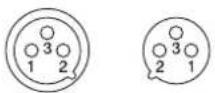 XLR Jack XLR Jack |
| * L I NE (mono channels)GROUP OUT, STEREO OUT,MONITOR OUT, FX SEND | Tip: Hot (+)Ring: Cold (−)Sleeve: Ground | 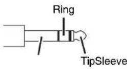 TRS Phone Jack TRS Phone Jack |
| INSERT | Tip: OutputRing: InputSleeve: Ground | |
| PHONES | Tip: LRing: RSleeve: Ground | |
| RETURNLINE (stereo channels) | Tip: HotSleeve: Ground | 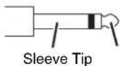 Phone Jack Phone Jack |
* These jacks will also accept connection to phone plugs. If you use monaural plugs, the connection will be unbalanced.
Specifications
■Electrical Characteristics
0 dBu=0.775 Vrms, 0 dBV=1 Vrms
All faders are set to nominal position if not specified. (Nominal position is adjusted to a position that is 10 dB lower than the maximum position) Output impedance of signal generator(Rs)=150 ohms, Output load impedance=10k ohms (TRS phone output), 600 ohms (XLR output)
| UNIT | ||||
| Frequency Response | 20 Hz–20 kHz, refer to the nominal output level @1 kHzGAIN: min (MONO CH, STEREO CH) | +0.5/-1.0 | dB | |
| Total Harmonic Distortion STEREO OUT +14 | dBu@20 Hz–20 kHz, GAIN: min 0.02 % | |||
| Noise*1 | CH INPUT EIN | (Equivalent Input Noise): Rs=150 ohms, GAIN: max -128 dBu | ||
| STEREO OUT GROUP OUT | STEREO and GROUP master faders are at nominal position and all of bus assign switches are off. | -92 dBu | ||
| AUX SEND FX SEND | AUX and FX master controls are at nominal position, and all of CH mix controls are at minimum position. | -83 dBu | ||
| STEREO OUT Residual Output Noise -102 dBu | ||||
| Crosstalk at 1 kHz*2 | Adjacent Input | Between input channels | -74 | dB |
| Input to Output | STEREO OUT L/R, PAN: panned hard left or right | -74 | dB | |
| Maximum Voltage Gain (1 kHz)*3 | CH INPUT MIC to | CH INSERT OUT | 60 | dB |
| STEREO OUT | 84 | dB | ||
| GROUP OUT | 84 | dB | ||
| REC OUT | 62 | dB | ||
| MONITOR OUT | 80 | dB | ||
| PHONES OUT | 69 | dB | ||
| AUX SEND (AUX2: PRE) | 76 | dB | ||
| AUX SEND (AUX2: POST) | 86 | dB | ||
| FX SEND | 86 | dB | ||
| RETURN to | STEREO OUT | 16 | dB | |
| AUX SEND | 12 | dB | ||
| 2TR IN to | STEREO OUT | 28 | dB | |
| MONITOR OUT | 34 | dB | ||
*1 Noise is measured with an A-Weighting filter.
*2 Crosstalk is measured with a 1 kHz band pass filter.
*3 Maximum voltage gain is measured under the condition that all faders and GAIN controls are at maximum. PAN/BAL controls are panned hard left or right.
■General Specifications
| Supported iPod/iPhone models (as of Dec. 2011) | ^* iPod classic, iPod touch ( 1^st - 4^th generation), iPod nano ( 2^nd - 6^th generation), iPhone 4S, iPhone 4, iPhone 3GS, iPhone 3G, iPhone | |
| Input Channel HPF | 100 Hz, 12 dB/oct | |
| Input Channel EQ | HIGH | 8 kHz, shelving |
| MID | MGP16X CHs 1–8, 13–16: 250 Hz to 5 kHz, peaking MGP16X CHs 9–12: 2.5 kHz, peakingMGP12X CHs 1–4, 9–12: 250 Hz to 5 kHz, peaking MGP12X CHs 5–8: 2.5 kHz, peaking | |
| LOW | 125 Hz, shelving | |
| Input Channel Compressor | Parameters (ratio, threshold, output gain) are controlled by one knob. | |
| Signal Indicator | CH INPUT | PEAK indicator (red)SIG indicator (green)PEAK lights if the signal comes within 3 dB of the clipping level. |
| LED Level Meter | 2 x 12 segments LED meter(PEAK, +10, +6, +3, 0, -3, -6, -10, -15, -20, -25, -30 dB)Metering point: post stereo master fader or pre monitor level | |
| Phantom Power | +48V | |
| Power Supply | Requirements 100–240 V 50/60 Hz, auto sensing, IEC input | |
| Power Consumption | MGP16X: 55 watts maxMGP12X: 45 watts max | |
| Dimensions (W x H x D) | MGP16X: 447 mm x 143 mm x 495 mm (17.6" x 5.6" x 19.5")MGP12X: 348 mm x 143 mm x 495 mm (13.7" x 5.6" x 19.5") | |
| Weight | MGP16X: 9.0 kg (19.8 lb)MGP12X: 7.5 kg (16.5 lb) | |
* The device may not function depending on your iPod/iOS software version. For updated information about supported software versions, check the Yamaha Pro Audio website (http://www.yamahaproaudio.com/).
■Analog Input Specifications
| Input Connectors | PADGain | Input Impedance | Appropriate Impedance | Input level | Connector Specifications | |||
| Sensitivity*1 | Nominal | Max. before Clipping | ||||||
| MONO CH INPUTMGP16X: 1-8MGP12X: 1-4 | 0 | -60 dB | 36 dBu (123k ohms) | 50-600Ohms Mio3dB | -80 dBu (0.078 mV) | -60 dBu (0.775 mV) | -40 dBu (7.75 mV) | Combo jack*2 |
| -16 dB | Bu (123 mV) +4 dBu (1.23 V) | |||||||
| 26 dB | -34 dB | -10 dBu (245 mV) | 600 ohms | -54 dBu (1.55 mV) | -34 dBu (15.5 mV) | -14 dBu (155 mV) | ||
| +10 dB | Bu (2.45 V) +30 dBu (24.5 V) | |||||||
| STEREO CH INPUTMGP16X: 9-12MGP12X: 5-8 | — | -60 dB | 3k ohms | 50-600Ohms Mio3dB | -80 dBu (0.078 mV) | -60 dBu (0.775 mV) | -40 dBu (7.75 mV) | XLR-3-31 type*3 |
| -16 dB | Bu (123 mV) -6 dBu (389 mV) | |||||||
| — | -34 dB | 10k ohms | 600 ohms | -54 dBu (1.55 mV) | -34 dBu (15.5 mV) | -14 dBu (155 mV) | Phone jack*4 | |
| +10 dB | Bu (2.45 V) | +30 dBu (24.5 V) | ||||||
| STEREO CH INPUTMGP16X: 13-16MGP12X: 9-12 | — | -34 dB | 10k ohms | 600 ohms | -54 dBu (1.55 mV) | -34 dBu (15.5 mV) | -14 dBu (155 mV) | Phone jack*4RCA pin jack |
| — | +10 dB | Bu (2.45 V) | +30 dBu (24.5 V) | |||||
| MONO CH INSERT INMGP16X: 1-8MGP12X: 1-4 | — | — | 10k ohms | 600 ohmsLines | -20 dBu (77.5 mV) | 0 dBu (0.775 V) | +20 dBu (7.75 V) | Phone jack(TRS)*5 |
| RETURN (L, R) | — | — | 10k ohms | 600 ohmsLines | -12 dBu (195 mV) | +4 dBu (1.23 V) | +24 dBu (12.3 V) | Phone jack*4 |
| 2TR IN (L, R) | — | — | 10k ohms | 600 ohmsLines | -26 dBV (50.1 mV) | -10 dBV (0.316 V) | +10 dBV (3.16 V) | RCA pin jack |
0 dBu=0.775 Vrms, 0 dBV=1 Vrms
*1 Sensitivity: The lowest level that will produce an output of +4 dB (1.23 V), or the nominal output level when the unit is set to maximum level. (All faders and level controls are at their maximum position.)
*2 Combo jacks are balanced (1&Sleeve=GND, 2&Tip=HOT, 3&Ring=COLD)
*3 XLR-3-31 type connectors are balanced. (1=GND, 2=HOT, 3=COLD)
*4 Phone jacks are unbalanced.
*5 Phone jacks are unbalanced. (Tip=Out, Ring=In, Sleeve=GND)
■Analog Output Specifications
| Output Connectors | Output Impedance | Appropriate Impedance | Output Level | Connector Specifications | |
| Nominal | Max. before Clipping | ||||
| STEREO OUT (L, R) | 75 ohms | 600 ohms Lines | +4 dBu (1.23 V) | +24 dBu (12.3 V) | XLR-3-32 type*1Phone jack*4 |
| GROUP OUT (1–4) | 150 ohms | 10k ohms Lines | +4 dBu (1.23 V) | +20 dBu (7.75 V) | Phone jack*2 |
| AUX SEND (1, 2) | 75 ohms | 600 ohms Lines | +4 dBu (1.23 V) | +24 dBu (12.3 V) | XLR-3-32 type *1 |
| FX SEND (1, 2) | 150 ohms | 10k ohms Lines | +4 dBu (1.23 V) | +20 dBu (7.75 V) | Phone jack*2 |
| MONO CH INSERT OUTMGP16X: 1–8MGP12X: 1–4 | 150 ohms | 10k ohms Lines | 0 dBu (0.775 V) | +20 dBu (7.75 V) | Phone jack*3 |
| REC OUT (L, R) | 600 ohms | 10k ohms Lines | -10 dBV (0.316 V) | +10 dBV (3.16 V) | RCA pin jack |
| MONITOR OUT (L, R) | 150 ohms | 10k ohms Lines | +4 dBu (1.23 V) | +20 dBu (7.75 V) | Phone jack*2 |
| PHONES | 100 ohms | 40 ohms Phones | 3 mW | 75 mW | Stereo phone jack |
0 dBu=0.775 Vrms, 0 dBV=1 Vrms
*1 XLR-3-32 type connectors are balanced. (1=GND, 2=HOT, 3=COLD)
*2 Phone jacks are impedance balanced. (Tip=HOT, Ring=COLD, Sleeve=GND)
*3 Phone jacks are unbalanced. (Tip=Out, Ring=In, Sleeve=GND)
*4 Phone jacks are balanced. (Tip=HOT, Ring=COLD, Sleeve=GND)
■Digital Input Specifications
| Connector | Format | Connector Specification |
| USB IN | iPod, iPhone exclusive | USB A type |
Dimensions
MGP16X
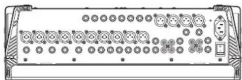
natural_image
Front view of a device chassis with multiple circular components and a control panel (no text or symbols visible)447 (444 excluding screw heads)
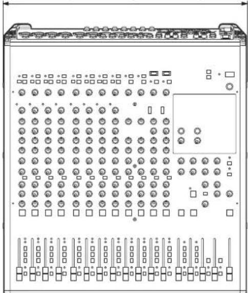
natural_image
Technical line drawing of a server rack with indicator lights and ports (no text or symbols)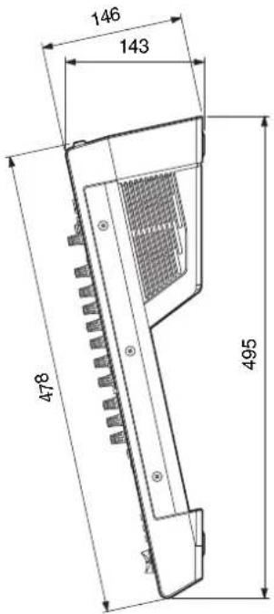
MGP12X
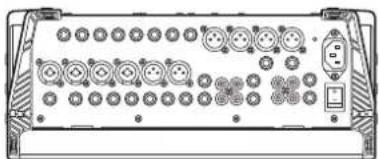
natural_image
Front view of a device rear panel with multiple ports and connectors (no visible text or labels)348 (345 excluding screw heads)
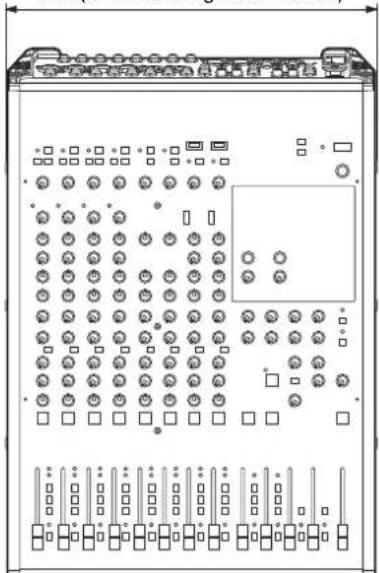
natural_image
Front view diagram of an electronic control panel with multiple ports and indicator lights (no text or labels)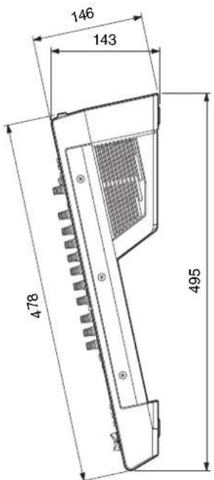
Unit: mm
* Specifications and descriptions in this owner's manual are for information purposes only. Yamaha Corporation reserves the right to modify products or specifications at any time without prior notice. Since specifications, equipment, and options may not be the same in every locale, please check with your Yamaha dealer.
Block Diagram and Level Diagram
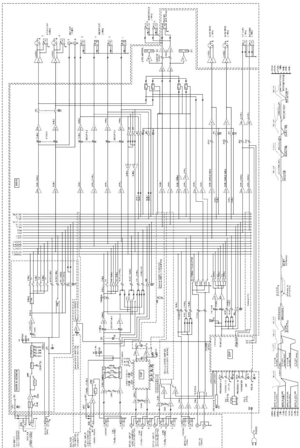
flowchart
Electrical circuit diagram with main components including MAIN, MAIN & MONC4, ST CH INPUT, and various signal paths and modules labeled in English.Important Notice: Guarantee Information for customers in European Economic Area (EEA) and Switzerland
| Tärkeä ilmoitus: Takuutiedot Euroopan talousalueen (ETA)* ja Sveitsin asiakkaille | Suomi |
| Tämän Yamaha-tuotteen sekä ETA-alueen ja Sveitsin takuuta koskevat yksityiskohtaiset tiedot saatte alla olevasta nettiosoit-teesta. (Tulostettava tiedosto saatavissa sivustollamme.) Voitte myös ottaa yhteyttä paikalliseen Yamaha-edustajaan.*ETA: Euroopan talousalue | |
| Ważne: Warunki gwarancyjne obowiązujące w EOG* i Szwajcarii | Polski |
| Aby dowiedzieć się więcej na temat warunków gwarancyjnych tego produktu firmy Yamaha i serwisu gwarancyjnego w całym EOG* i Szwajcarii, należy odwiedzić wskazaną poniżej stronę internetową (Plik gotowy do wydruku znajduje się na naszej stronie internetowej) lub skontaktować się z przedstawicielstwem firmy Yamaha w swoim kraju. * EOG — Europejski Obszar Gospodarczy | |
| Dûležité oznámení: Záruční informace pro zákazníky v EHS* a ve Švýcarsku | Česky |
| Podrobné záruční informace o tomto produktu Yamaha a záručním servisu v celém EHS* a ve Švýcarsku naleznete na níže uvedené webové adrese (soubor k tisku je dostupný na našich webových stránkách) nebo se můžete obrátit na zastoupení firmy Yamaha ve své zemi. * EHS: Evropsky hospodářský prostor | |
| Fontos figyelmeztetés: Garancia-információk az EGT* területén és Svájcban élő vásárlók számára | Magyar |
| A jelen Yamaha termékre vonatkozó részletes garancia-információk, valamint az EGT*-re és Svájcra kiterjedő garanciális szolgáltatás tekintetében keresse fel webhelyünket az alábbi címen (a webhelyen nyomtatható fájlt is talál), vagy pedig lépjen kapcsolatba az országában můködő Yamaha képviseleti irodával. * EGT: Európai Gazdasági Térseg | |
| Oluline márkus: Garantiiteave Euroopa Majanduspiirkonna (EMP)* ja Šveitsi klientidele | Eesti keel |
| Täpsema teabe saamiseks selle Yamaha toote garantii ning kogu Euroopa Majanduspiirkonna ja Šveitsi garantiiteeninduse kohta, kůlastage palun veebisaiti alljärgneval aadressil (meie saidil on saadaval prinditav fail) või põörduge Teie regiooni Yamaha esinduse poole. * EMP: Euroopa Majanduspiirkond | |
| Svarīgs pazipojums: garantijas informacija klientiem EEZ* un Šveicē | Latviešu |
| Lai saņemtu detalizētu garantijas informaciju par šo Yamaha produktu, kā arī garantijas apkalpošanu EEZ* un Šveicē, lūdzu, apmeklějiet zemák norádílo tīmekļa vietnes adresi (tīmekļa vietně ir pieejams drukājams fails) vai sazinieties ar jūsu valsti apkalpojošo Yamaha pārstāvniecību. * EEZ: Europas Ekonomikas zona | |
| Dèmesio: informacija dėl garantijos pirkėjams EEE* ir Šveicarijoje | Lietuvių kalba |
| Jei reikia išsamios informacijos apie šj „Yamaha” produktą ir jo techninę priežiūrą visoje EEE* ir Šveicarijoje, apsilankykite mūsų svetainėje toliau nurodytu adresu (svetainėje yra spausdintinas faīlas) arba kreipkitės į „Yamaha” atstovybę savo šaliai.*EEE – Europos ekonominė erdvė | |
| Dôležité upozornenie: Informacie o záruke pre zákazníkov v EHP* a Švajčiarsku | Slovenčina |
| Podrobné informacie o záruke týkajúce sa tohto produktu od spoločnosti Yamaha a garančnom servise v EHP* a Švajčiarsku nájdete na webovej stránke uvedenej nižšie (na našej webovej stránke je k dispozícii súbor na tlač) alebo sa obrátte na zástupcu spoločnosti Yamaha vo svojej krajine. * EHP: Európsky hospodársky priestor | |
| Pomembno obvestilo: Informacije o garanciji za kupce v EGP* in Švici | Slovenščina |
| Za podrobnejše informacije o tem Yamahinem izdelku ter garancijskem servisu v celotnem EGP in Švici, obiščite spletno mesto, ki je navedeno spodaj (natisljiva datoteka je na voljo na našem spletnem mestu), ali se obrnite na Yamahinega predstavnika v svoji državi. * EGP: Evropski gospodarski prostor | |
| Bawno съобщение: Информация за гаранцията за клиенти в ЕИП* и Швейцария | Български език |
| За подробна информация за гаранцията за този продукт на Yamaha и гаранционното обслужване в паневропейската зона на ЕИП* и Швейцария или посетете посочения по-долу уеб сайт (на нашия уеб сайт има файл за печат), или се свържете с представителния офис на Yamaha във вашата страна. * ЕИП: Европейско икономическо пространство | |
| Notificare importantă: Informații despre garanție pentru clientii din SEE* și Elveția | Limba română |
| Pentru informații detaliate privind acest produs Yamaha și serviciul de garanție Pan-SEE* și Elveția, vizitați site-ul la adresa de mai jos (fișierul imprimabil este disponibil pe site-ul nostru) sau contactați biroul reprezentanței Yamaha din țara dumneavoastră .* SEE: Spațiul Economic European | |
| Important Notice: Guarantee Information for customers in EEA* and SwitzerlandFor detailed guarantee information about this Yamaha product, and Pan-EEA* and Switzerland warranty service, please either visit the website address below (Printable file is available at our website) or contact the Yamaha representative office for your country. * EEA: European Economic Area | English |
| Wichtiger Hinweis: Garantie-Information für Kunden in der EWR* und der SchweizFür nähere Garantie-Information über dieses Produkt von Yamaha, sowie über den Pan-EWR*- und Schweizer Garantiservice, besuchen Sie bitte entweder die folgend angegebene Internetadresse (eine druckfähige Version befindet sich auch auf unserer Webseite), oder wenden Sie sich an den für Ihr Land zuständigen Yamaha-Vertrieb. *EWR: Europäischer Wirtschaftsraum | Deutsch |
| Remarque importante: informations de garantie pour les clients de l'EEE et la SuissePour des informations plus détaillées sur la garantie de ce produit Yamaha et sur le service de garantie applicable dans l'ensemble de l'EEE ainsi qu'en Suisse, consultez notre site Web à l'adresse ci-dessous (le fichier imprimable est disponible sur notre site Web) ou contactez directement Yamaha dans votre pays de résidence. * EEE : Espace Economique Européen | Français |
| Belangrijke mededeling: Garantie-informatie voor klanten in de EER* en ZwitserlandVoor gedetailleerde garantie-informatie over dit Yamaha-product en de garantieservice in heel de EER* en Zwitserland, gaat u naar de onderstaande website (u vind een afdrukbaar bestand op onze website) of neemt u contact op met de vertegenwoordiging van Yamaha in uw land. * EER: Europese Economische Ruimte | Nederlands |
| Aviso importante: información sobre la garantía para los clientes del EEE* y SuizaPara una información detallada sobre este producto Yamaha y sobre el soporte de garantía en la zona EEE* y Suiza, visite la dirección web que se incluye más abajo (la version del archivo para imprimir esta disponible en nuestro sitio web) o póngase en contacto con el representante de Yamaha en su país. * EEE: Espacio Económico Europeo | Español |
| Avviso importante: informazioni sulla garanzia per i clienti residenti nell'EEA* e in SvizzeraPer informazioni dettagliate sulla garanzia relativa a questo prodotto Yamaha e l'assistenza in garanzia nei paesi EEA* e in Svizzera, potete consultare il sito Web all'indirizzo riportato di seguito (è disponibile il file in formato stampabile) oppure contattare l'ufficio di rappresentanza locale della Yamaha. * EEA: Area Economica Europea | Italiano |
| Aviso importante: informações sobre as garantias para clientes da AEE* e da SuíçaPara obter uma informação pormenorizada sobre este produto da Yamaha e sobre o serviço de garantia na AEE* e na Suíça, visite o site a seguir (o arquivo para impressão está disponível no nosso site) ou entre em contato com o escritório de representação da Yamaha no seu país. * AEE: Área Econômica Européia | Português |
| Σημαντική σημείωση: Πληροφορίες εγγύησης για τους πελάτες στον ΕΟΧ* και ΕλβετίαΓια λεπτομερείς πληροφορίες εγγύησης σχετικά με το παρόν προϊόν της Yamaha και την κάλυψη εγγύησης σε όλες τις χώρες του ΕΟΧ και την Ελβετία, επισκεφετείτε την παρακάτω ιστοσελίδα (Εκτυπώσιμη μορφή είναι διαθέσιμη στην ιστοσελίδα μας) ή απευθυνθείτε στην αντιπροσωπεία της Yamaha στη χώρα σας. * ΕΟΧ: Ευρωπαϊκός Οικονομικός Χώρος | Ελληνικά |
| Viktigt: Garantiinformation för kunder i EES-området* och SchweizFör detaljerad information om denna Yamahaprodukt samt garantiservice i hela EES-området* och Schweiz kan du antingen besöka nedanstående webbaddress (en utskriftsvänlig fil finns på webbplatsen) eller kontakta Yamahas officiella representant i ditt land. * EES: Europeiska Ekonomiska Samarbetsområdet | Svenska |
| Viktig merknad: Garantiinformasjon for kunder i E∅S* og SveitsDetaljert garantiinformasjon om dette Yamaha-produktet og garantiservice for hele E∅S-området* og Sveits kan fås enten ved å besøke nettadressen nedenfor (utskriftsversjon finnes på våre nettsider) eller kontakte kontakte Yamaha-kontoret i landet der du bor. *E∅S: Det europeiske økonomiske samarbeidsområdet | Norsk |
| Vigtig oplysning: Garantioplysninger til kunder i E∅O* og SchweizDe kan finde detaljerede garantioplysninger om dette Yamaha-produkt og den fælles garantiserviceordning for E∅O* (og Schweiz) ved at besøge det websted, der er angivet nedenfor (der findes en fil, som kan udskrives, på vores websted), eller ved at kontakte Yamahas nationale repräsentationskontor i det land, hvor De bor. * E∅O: Det Europæiske ∅konomiske Område | Dansk |
http://europe.yamaha.com/warranty/
URL_4
FCC INFORMATION (U.S.A.)
1. IMPORTANT NOTICE: DO NOT MODIFY THIS UNIT!
This product, when installed as indicated in the instructions contained in this manual, meets FCC requirements. Modifications not expressly approved by Yamaha may void your authority, granted by the FCC, to use the product.
- IMPORTANT: When connecting this product to accessories and/or another product use only high quality shielded cables. Cable/s supplied with this product MUST be used. Follow all installation instructions. Failure to follow instructions could void your FCC authorization to use this product in the USA.
- NOTE: This product has been tested and found to comply with the requirements listed in FCC Regulations, Part 15 for Class "B" digital devices. Compliance with these requirements provides a reasonable level of assurance that your use of this product in a residential environment will not result in harmful interference with other electronic devices. This equipment generates/uses radio frequencies and, if not installed and used according to the instructions found in the users manual, may cause interference harmful to the operation of other electronic devices. Compliance with FCC regulations does not guarantee that interference will not occur in all
installations. If this product is found to be the source of interference, which can be determined by turning the unit "OFF" and "ON", please try to eliminate the problem by using one of the following measures:
Relocate either this product or the device that is being affected by the interference.
Utilize power outlets that are on different branch (circuit breaker or fuse) circuits or install AC line filter/s.
In the case of radio or TV interference, relocate/reorient the antenna. If the antenna lead-in is 300 ohm ribbon lead, change the lead-in to co-axial type cable.
If these corrective measures do not produce satisfactory results, please contact the local retailer authorized to distribute this type of product. If you can not locate the appropriate retailer, please contact Yamaha Corporation of America, Electronic Service Division, 6600 Orangethorpe Ave, Buena Park, CA90620
The above statements apply ONLY to those products distributed by Yamaha Corporation of America or its subsidiaries.
* This applies only to products distributed by YAMAHA CORPORATION OF AMERICA.
(class B)
This device complies with Part 15 of the FCC Rules. Operation is subject to the following two conditions:
(1) this device may not cause harmful interference, and (2) this device must accept any interference received, including interference that may cause undesired operation.
CANADA
This Class B digital apparatus complies with Canadian ICES-003.
IMPORTANT NOTICE FOR THE UNITED KINGDOM Connecting the Plug and Cord
WARNING: THIS APPARATUS MUST BE EARTHED IMPORTANT. The wires in this mains lead are coloured in accordance with the following code:
GREEN-AND-YELLOW : EARTH
BLUE : NEUTRAL
BROWN: L I V E
As the colours of the wires in the mains lead of this apparatus may not correspond with the coloured markings identifying the terminals in your plug proceed as follows:
The wire which is coloured GREEN-and-YELLOW must be connected to the terminal in the plug which is marked by the letter E or by the safety earth symbol ⏻ or colored GREEN or GREEN-and-YELLOW.
The wire which is coloured BLUE must be connected to the terminal which is marked with the letter N or coloured BLACK.
The wire which is coloured BROWN must be connected to the terminal which is marked with the letter L or coloured RED.
(3 wires)

Information for Users on Collection and Disposal of Old Equipment
This symbol on the products, packaging, and/or accompanying documents means that used electrical and electronic products should not be mixed with general household waste.
For proper treatment, recovery and recycling of old products, please take them to applicable collection points, in accordance with your national legislation and the Directives 2002/96/EC.
By disposing of these products correctly, you will help to save valuable resources and prevent any potential negative effects on human health and the environment which could otherwise arise from inappropriate waste handling.
For more information about collection and recycling of old products, please contact your local municipality, your waste disposal service or the point of sale where you purchased the items.
[For business users in the European Union]
If you wish to discard electrical and electronic equipment, please contact your dealer or supplier for further information.
[Information on Disposal in other Countries outside the European Union]
This symbol is only valid in the European Union. If you wish to discard these items, please contact your local authorities or dealer and ask for the correct method of disposal.
(weee_eu)
For details of products, please contact your nearest Yamaha representative or the authorized distributor listed below.
Yamaha Canada Music Ltd.
135 Milner Avenue, Scarborough, Ontario,
M1S 3R1, Canada
Tel: 416-298-1311
U.S.A.
Yamaha Corporation of America
6600 Orangethorpe Ave., Buena Park, Calif. 90620,
U.S.A.
Tel: 714-522-9011
CENTRAL & SOUTH AMERICA
MEXICO
PANAMA AND OTHER LATIN
AMERICAN COUNTRIES/
CARIBBEAN COUNTRIES
Yamaha Music Latin America, S.A.
Sherbourne Drive, Tilbrook, Milton Keynes,
MK7 8BL, England
Tel: 01908-366700
GERMANY
Yamaha Music Europe GmbH
Siemensstraße 22-34, 25462 Rellingen, Germany
Tel: 04101-3030
Branch Switzerland in Zürich
Seefeldstrasse 94, 8008 Zürich, Switzerland
Tel: 044-387-8080
AUSTRIA/BULGARIA
Yamaha Music Europe GmbH Branch Austria
Schleiergasse 20, A-1100 Wien, Austria
Tel: 01-60203900
CZECH REPUBLIC/HUNGARY/
ROMANIA/SLOVAKIA/SLOVENIA
Yamaha Music Europe GmbH
Branch Austria (Central Eastern Europe Office)
Schleiergasse 20, A-1100 Wien, Austria
Tel: 01-602039025
POLAND/LITHUANIA/LATVIA/ESTONIA
Yamaha Music Europe GmbH
Yamaha Music Europe GmbH, Branch Italy
Viale Italia 88, 20020 Lainate (Milano), Italy
Tel: 02-935-771
SPAIN/PORTUGAL
Yamaha Music Europe GmbH Ibérica, Sucursal
en España
Ctra. de la Coruna km. 17, 200, 28230
Las Rozas (Madrid), Spain
Tel: +34-902-39-8888
GREECE
Philippos Nakas S.A. The Music House
147 Skiathou Street, 112-55 Athens, Greece
Tel: 01-228 2160
SWEDEN/FINLAND/ICELAND
Yamaha Music Europe GmbH Germany filial
Scandinavia
J. A. Wettergrens Gata 1, Box 30053
S-400 43 Göteborg, Sweden
Tel: 031 89 34 00
DENMARK
Yamaha Music Europe GmbH, Tyskland – filial
Denmark
Generatorvej 6A, DK-2730 Herlev, Denmark
Tel: 44 92 49 00
NORWAY
Yamaha Music Europe GmbH Germany -
Norwegian Branch
Grini Næringspark 1, N-1345 ∅sterås, Norway
Tel: 67 16 77 70
RUSSIA
Yamaha Music (Russia)
Room 37, bld. 7, Kievskaya street, Moscow,
121059, Russia
Tel: 495 626 5005
OTHER EUROPEAN COUNTRIES
Yamaha Music Europe GmbH
Siemensstraße 22-34, 25462 Rellingen, Germany
Tel: +49-4101-3030
AFRICA
Yamaha Corporation,
Asia-Pacific Sales & Marketing Group
Nakazawa-cho 10-1, Naka-ku, Hamamatsu,
Japan 430-8650
Tel: +81-53-460-2303
MIDDLE EAST
TURKEY/CYPRUS
Yamaha Music Europe GmbH
Siemensstraße 22-34, 25462 Rellingen, Germany
Tel: 04101-3030
OTHER COUNTRIES
Yamaha Music Gulf FZE
LOB 16-513, P.O.Box 17328, Jubel Ali,
Dubai, United Arab Emirates
Tel: +971-4-881-5868
ASIA
THE PEOPLE'S REPUBLIC OF CHINA
Yamaha Music & Electronics (China) Co., Ltd.
2F, Yunhedasha, 1818 Xinzha-lu, Jingan-qu,
Shanghai, China
Tel: 021-6247-2211
INDIA
Yamaha Music India Pvt. Ltd.
Spazedge building, Ground Floor, Tower A, Sector
47, Gurgaon- Sohna Road, Gurgaon, Haryana, India
Tel: 0124-485-3300
INDONESIA
PT. Yamaha Musik Indonesia (Distributor)
PT. Nusantik
Gedung Yamaha Music Center, Jalan Jend. Gatot
Subroto Kav. 4, Jakarta 12930, Indonesia
Tel: 021-520-2577
KOREA
Yamaha Music Korea Ltd.
8F, 9F, Dongsung Bldg. 158-9 Samsung-Dong,
Kangnam-Gu, Seoul, Korea
Tel: 02-3467-3300
MALAYSIA
Yamaha Music (Malaysia) Sdn., Bhd.
Lot 8, Jalan Perbandaran, 47301 Kelana Jaya,
Petaling Jaya, Selangor, Malaysia
Tel: 03-78030900
SINGAPORE
Yamaha Music (Asia) PRIVATE LIMITED
Blk 202 Hougang Street 21, #02-00,
Singapore 530202, Singapore
Tel: 6747-4374
TAIWAN
Yamaha KHS Music Co., Ltd.
3F, #6, Sec.2, Nan Jing E. Rd. Taipei.
Taiwan 104, R.O.C.
Tel: 02-2511-8688
THAILAND
Siam Music Yamaha Co., Ltd.
4, 6, 15 and 16th floor, Siam Motors Building,
891/1 Rama 1 Road, Wangmai,
Pathumwan, Bangkok 10330, Thailand
Tel: 02-215-2622
OTHER ASIAN COUNTRIES
Yamaha Corporation,
Asia-Pacific Sales & Marketing Group
Nakazawa-cho 10-1, Naka-ku, Hamamatsu,
Japan 430-8650
Tel: +81-53-460-2303
OCEANIA
AUSTRALIA
Yamaha Music Australia Pty. Ltd.
Level 1, 99 Queensbridge Street, Southbank,
Victoria 3006, Australia
Tel: 3-9693-5111
COUNTRIES AND TRUST
TERRITORIES IN PACIFIC OCEAN
Yamaha Corporation,
Asia-Pacific Sales & Marketing Group
Nakazawa-cho 10-1, Naka-ku, Hamamatsu,
Japan 430-8650
Tel: +81-53-460-2303
- Explanation of Graphical Symbols
- IMPORTANT SAFETY INSTRUCTIONS
- WARNING
- ContentsMain Features
- Sophisticated analog circuits D-PRE (Discrete Class-A MIC preamp)
- EQ (equalizer)
- Digital effects — REV-X and SPX (pages 21, 28)
- Convenient, practical functions for events – Ducker, Leveler, and Stereo Image (pages 14, 18, 19)
- USB port for playing and charging your iPod/iPhone (page 20)
- Main Features ...... 3
- PRECAUTIONS......4
- Making the Most of Your Mixer...... 6
- Setup 8
- Quick Start Guide ......12
- Controls and Connectors......15
- Troubleshooting ....27
- Appendix....28
- Accessories
- PRECAUTIONS
- PLEASE READ CAREFULLY BEFORE PROCEEDING
- Power supply/Power cord
- Do not open
- Water warning
- Fire warning
- If you notice any abnormality
- CAUTION
- Location
- Connections
- Maintenance
- Handling caution
- NOTICE
- ■ Handling and Maintenance
- ■ Connectors
- Information
- ■ About copyrights
- ■ About this manual
- iPodTM, iPhoneTM
- Balanced Cables and Unbalanced Cables
- Connector Types
- XLR connectors
- Phone jacks
- RCA Pin Connectors
- Level Adjustment for Optimum Mix
- Equalizer Tips
- - Cut for a Cleaner Mix
- Comp settings
- Use the High-pass Filter for Microphone Input
- Start with the Featured Part
- Setup Examples
- Sound Reinforcement for Live Performance
- Rack Mounting
- ■ Precautions for Rack Mounting
- ■ Mounting the MGP16X/MGP12X
- MGP16X
- MGP12X
- Security Cover Mounting
- Step 1 Preparing the Power Supply
- Step 2 Connections
- Connect the microphones and/or instruments you intend to use.
- Step 3 Powering Up the System
- Step 4 Getting Sound to the Speakers
- NOTE
- Step 5 Using the Built-in Digital Effects
- ■ Built-in digital effects
- Reverb and Delay Time
- Reverb Tone
- Reverb Level
- Step 6 Using the Ducker function
- Channel Control Block
- Master Control Block
- Rear Panel
- Rear Input/Output Block
- Where Your Signal Goes Once It's Inside the Box
- ■ Input channel
- ①Head amp
- ②Equalizer
- ③PEAK indicator
- ④Channel fader
- ■ Master section
- ⑤Bus (Summing Amplifier)
- ⑥Master control and level meter
- Mono input section Mono and stereo input section Stereo input section
- ①+48V switch and indicator
- ②26dB (PAD) switch
- ③ (High Pass Filter) switch
- ④DUCKER switch
- ⑤LEVELER switch and indicator
- ⑥GAIN control
- Stereo channel
- ⑦COMP control and indicator
- ⑧STEREO IMAGE switch
- ⑨Equalizer (HIGH, MID, and LOW)
- ⑩AUX1 PRE, AUX2 controls
- ⑪PRE switch
- ⑫FX1, FX2 controls
- ⑬PAN control
- PAN/BAL control
- BAL control
- ⑭ON switch
- ⑮Input Meter
- ⑯Bus assign switches
- ⑰PFL switch and indicator
- ⑱Channel fader
- iPod/iPhone section
- ①USB connector and indicator
- ②Routing assign switches
- ■ About the Detailed Setting Mode
- Procedure
- Built-in digital effects section
- ①Effect program display
- ②PROGRAM knob
- ③PARAMETER control
- ④ AUX PRE controls (1, 2)
- ⑤TAP button and indicator
- ⑥ON button
- ⑦SIG indicator
- ⑧Bus assign switches
- ⑨PFL switch and indicator
- ⑩FX RTN faders (FX1, FX2)
- Meter/PHONES section
- ①PHONES jack
- ②POWER indicator
- ③Level meter
- ④MONITOR/PHONES control
- RETURN/2TR IN section
- ①RETURN
- ②2TR IN
- SEND MASTER section
- ①SEND MASTER controls (AUX1, AUX2, FX1, FX2)
- ②AFL switch and indicator
- GROUP/STEREO section
- ①GROUP 1-2 fader
- ②GROUP 3-4 fader
- ③ST switch
- ④AFL switch and indicator
- ⑤ON switch
- ⑥STEREO master fader
- Channel I/O connectors section
- ①Mono inputs
- ②Mono/Stereo inputs
- ③Stereo input
- Master I/O connectors section
- ④2TR IN
- ⑤REC OUT
- ⑥MONITOR OUT
- \* Impedance balanced
- ⑦RETURN
- ⑧GROUP OUT
- ⑨SEND
- ⑩STEREO OUT
- Power section
- ⑪POWER switch
- ⑫AC IN connector
- Digital Effect Program List
- Specifications
- ■Electrical Characteristics
- Dimensions
- Important Notice: Guarantee Information for customers in European Economic Area (EEA) and Switzerland
- http://europe.yamaha.com/warranty/
- FCC INFORMATION (U.S.A.)
- IMPORTANT NOTICE: DO NOT MODIFY THIS UNIT!
- CANADA
- IMPORTANT NOTICE FOR THE UNITED KINGDOM Connecting the Plug and Cord
- Information for Users on Collection and Disposal of Old Equipment
- [For business users in the European Union]
- [Information on Disposal in other Countries outside the European Union]
- U.S.A.
- CENTRAL & SOUTH AMERICA
- MEXICO
- PANAMA AND OTHER LATIN
- AMERICAN COUNTRIES/
- CARIBBEAN COUNTRIES
- GERMANY
- AUSTRIA/BULGARIA
- CZECH REPUBLIC/HUNGARY/
- ROMANIA/SLOVAKIA/SLOVENIA
- POLAND/LITHUANIA/LATVIA/ESTONIA
- SPAIN/PORTUGAL
- GREECE
- SWEDEN/FINLAND/ICELAND
- DENMARK
- NORWAY
- RUSSIA
- OTHER EUROPEAN COUNTRIES
- AFRICA
- MIDDLE EAST
- TURKEY/CYPRUS
- OTHER COUNTRIES
- ASIA
- THE PEOPLE'S REPUBLIC OF CHINA
- INDIA
- INDONESIA
- KOREA
- MALAYSIA
- SINGAPORE
- TAIWAN
- THAILAND
- OTHER ASIAN COUNTRIES
- OCEANIA
- AUSTRALIA
- COUNTRIES AND TRUST
- TERRITORIES IN PACIFIC OCEAN
Brand : YAMAHA
Model : MGP16X
Category : Blender