
Michi Q5 - CD Player ROTEL - Free user manual and instructions
Find the device manual for free Michi Q5 ROTEL in PDF.


| Product Type | CD Player / Transport DAC |
| Dimensions (W x H x D) | 485 x 150 x 452 mm (19 x 6 x 17 3/4 in) |
| Front Panel Height | 132 mm (5 1/4 in) |
| Weight (net) | 23.5 kg (51.8 lbs) |
| Power Requirements (USA) | 120 V, 60 Hz |
| Power Requirements (EC) | 230 V, 50 Hz |
| Power Consumption | 25 W |
| Standby Power Consumption | < 0.5 W |
| Digital-to-Analog Converter | ESS 32-bit/768 kHz DAC |
| Analog Output Level (RCA) | 2.3 V / 100 ohms |
| Analog Output Level (XLR) | 4.9 V / 4k ohms |
| CD Output (Digital) | 16-bit/44.1 kHz, 0 dBFS |
| Frequency Response | 20 Hz - 20 kHz (±0.1 dB); 10 Hz - 70 kHz (±3 dB) |
| Total Harmonic Distortion | < 0.0006% |
| Signal-to-Noise Ratio (IHF A-weighted) | > 115 dB |
| Dynamic Range | > 99 dB |
| Channel Separation | > 104 dB @ 10 kHz |
| PC-USB Input | USB Audio Class 2.0 (up to 32-bit/384 kHz PCM, DSD, MQA) |
| Coaxial/Optical Input | SPDIF LPCM (up to 24-bit/192 kHz) |
| Digital CD Output | Coaxial and Optical |
| Network Connection | Ethernet (RJ45) for firmware updates and IP control |
| RS232 Control | Yes (DB-9) |
| 12V Trigger Input | Yes (3-30 V AC/DC) |
| External IR Input | 3.5 mm mini-jack |
| Supported Disc Formats | CD (Red Book), MP3 CD |
| Remote Control | RR-RH9 (IR) with batteries (2x AAA) |
| Safety Certifications | FCC Class B, RoHS, WEEE, Class 1 Laser Product |
| Warranty | 2 years (typical, check local dealer) |
Frequently Asked Questions - Michi Q5 ROTEL
User questions about Michi Q5 ROTEL
0 question about this device. Answer the ones you know or ask your own.
Ask a new question about this device
Download the instructions for your CD Player in PDF format for free! Find your manual Michi Q5 - ROTEL and take your electronic device back in hand. On this page are published all the documents necessary for the use of your device. Michi Q5 by ROTEL.
USER MANUAL Michi Q5 ROTEL
Michi Q5
Transport DAC
Lecteur DAC
D/A-Wandler
This symbol is to alert the user to the presence of uninsulated dangerous voltages inside the product's enclosure that may constitute a risk of electric shock.

This symbol is to alert the user to important operating and maintenance (service) instructions in this manual and literature accompanying the product.
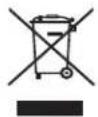
Michi products are designed to comply with international directives on the Restriction of Hazardous Substances (RoHS) in electrical and electronic equipment and the disposal of Waste Electrical and Electronic Equipment (WEEE). The crossed wheelie bin symbol indicates compliance and that the products must be appropriately recycled or processed in accordance with these directives.
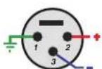
Pin Assignments
Balanced Audio (3 pole XLR):
Pin 1: Ground / Screen
Pin 2: In phase / +ve / Hot
Pin 3: Out of phase / -ve / Cold

AC symbol, Alternating current

Direct current

IMPORTANT FOR LASER PRODUCTS
1. CLASS 1 LASER PRODUCT
- DANGER: Visible laser radiation when open and interlock failed or bypassed. Avoid direct exposure to beam.
- CAUTION: Do not open the top cover. There are no user serviceable parts inside the player; leave all servicing to qualified service personnel.
WARNING!
To reduce the risk of electrical shock, fires, etc.:
- Do not remove screws, covers or cabinet.
- Do not expose the unit to rain or moisture.
- Do not touch the power cord or plug with wet hands.
Important Safety Instructions
Notice
The RS232 connection should be handled by authorized persons only.
WARNING: There are no user serviceable parts inside. Refer all servicing to qualified service personnel.
WARNING: To reduce the risk of fire or electric shock, do not expose the unit to moisture or water. Do not expose the unit to dripping or splashing. Do not place objects filled with liquids, such as vases, on the unit. Do not allow foreign objects to get into the enclosure. If the unit is exposed to moisture, or a foreign object gets into the enclosure, immediately disconnect the power cord from the wall. Take the unit to a qualified service person for inspection and necessary repairs.
Read these instructions.
Keep these instructions.
Heed all warnings.
Follow all instructions.
Do not use this apparatus near water.
Clean only with dry cloth.
Do not block any ventilation openings. Install in accordance with the manufacturer's instructions.
Do not install near any heat sources such as radiators, heat registers, stoves, or other apparatus (including amplifiers) that produce heat.
Do not defeat the safety purpose of the polarized or grounding-type plug. A polarized plug has two blades with one wider than the other. A grounding type plug has two blades and a third grounding prong. The wide blade or the third prong are provided for your safety. If the provided plug does not fit into your outlet, consult an electrician for replacement of the obsolete outlet.
Protect the power cord from being walked on or pinched particularly at plugs, convenience receptacles, and the point where they exit from the apparatus.
Only use attachments/accessories specified by the manufacturer.
Use only with the cart, stand, tripod, bracket, or table specified by the manufacturer, or sold with the apparatus. When a cart is used, use caution when moving the cart/apparatus combination to avoid injury from tip-over.

Unplug this apparatus during lightning storms or when unused for long periods of time.
Refer all servicing to qualified service personnel. Servicing is required when the apparatus has been damaged in any way, such as power supply cord or plug is damaged, liquid has been spilled or objects have fallen into the apparatus, the apparatus has been exposed to rain or moisture, does not operate normally, or has been dropped.
The apparatus should be used in non tropical climate.
The ventilation should not be impeded by covering the ventilation openings with items, such as newspapers, table-cloths, curtains, etc.
No naked flame sources, such as lighted candles, should be placed on the apparatus.
Touching uninsulated terminals or wiring may result in an unpleasant sensation.
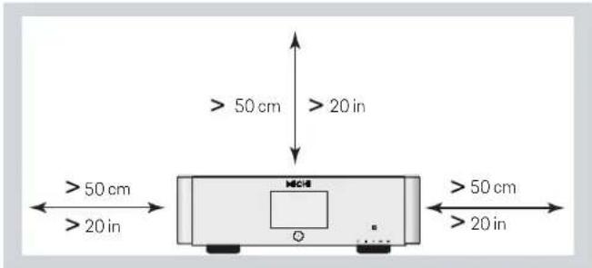
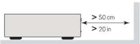
You must allow a minimum 50 cm or 20 inches of unobstructed clearance around the unit.
WARNING: The rear panel power cord connector is the mains power disconnect device. The device must be located in an open area that allows access to the cord connector.
The unit must be connected to a power supply only of the type and voltage specified on the rear panel. (USA: 120 V/60Hz, EC: 230V/50Hz)
Connect the component to the power outlet only with the supplied power supply cable or an exact equivalent. Do not modify the supplied cable. Do not use extension cords.
The mains plug is the disconnect of the unit. In order to completely disconnect the unit from the supply mains, remove the main plug from the
unit and the AC power outlet. This is the only way to completely remove mains power from the unit.
The batteries in the remote control should not be exposed to excessive temperature such as sunshine, fire or other heat sources. Batteries should be recycled or disposed as per state and local guidelines.
WARNING: The master power switch is located on the rear panel. The unit must allow unobstructed access to the main power switch.
This product shall be connected to a MAINS socket outlet with a protective earthing connection.
The MAINS plug or an appliance coupler is used as the disconnect device, the socket-outlet shall be installed near the equipment and shall be easily accessible.
FCC Information
This equipment has been tested and found to comply with the limits for a Class B digital device, pursuant to Part 15 of the FCC Rules. These limits are designed to provide reasonable protection against harmful interference in a residential installation. This equipment generates, uses and can radiate radio frequency energy and, if not installed and used in accordance with the instruction, may cause harmful interference to radio communications.
However, there is no guarantee that interference will not occur in a particular installation. If this equipment does cause harmful interference to radio or television reception, which can be determined by turning the equipment off and on, the user is encouraged to try to correct the interference by one or more of the following measures:
- Reorient or relocate the receiving antenna.(TV, radio, etc.)
- Increase the separation between the equipment and receiver.
- Connect the equipment to an outlet on circuit different from that to which the receiver is connected.
- Consult the dealer or an experienced radio/TV technician for additional help.
Caution
This device complies with part 15 of the FCC Rules. Operation is subject to the following to conditions: (1) This device may not cause harmful interference, and (2) this device must accept any interference received, including interference that may cause undesired operation.
NOTE: This equipment has been tested and found to comply with the limits for a Class B digital device, pursuant to Part 15 of the FCC Rules. These limits are designed to provide reasonable protection against interference in a residential installation. This equipment generates and can radiate radio frequency energy and, if not installed and used in accordance with the instructions, may cause interference to radio or TV communications. There is no guarantee that interference will not occur in a particular installation. If this equipment does cause interference to radio or television reception, which can be determined by turning the equipment off and on, try to correct the interference by one or more of the following measures:
- Reorient or relocate the receiving antenna.
- Increase the separation between the unit and the television tuner.
- Connect the unit to an AC power outlet on a different electrical circuit.
- Consult your authorized Rotel retailer for assistance.
Figure 1_1: Controls and Connections Commandes et Branchements Bedienelemente und -Anschlüsse Controles y Conexiones
Bedieningselementen en aansluitingen
Controlli e connessioni
Kontroller och anslutningar
Органы управления и разъемы
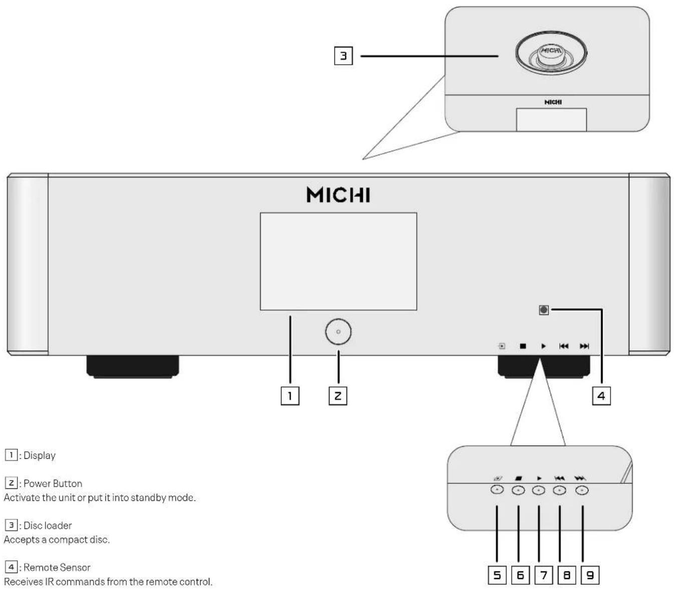
5: Source Button
Used to select the desired listening source.
6: STOP Button
Stop disc play.
7: PLAY Button
Start playing the disc.
89: TRACK Buttons
Select tracks on the disc.
Figure 1_2: Controls and Connections Commandes et Branchements Bedienelemente und -Anschlüsse Controles y Conexiones
Bedieningselementen en aansluitingen
Controlli e connessioni
Kontroller och anslutningar
Органы управления и разъемы
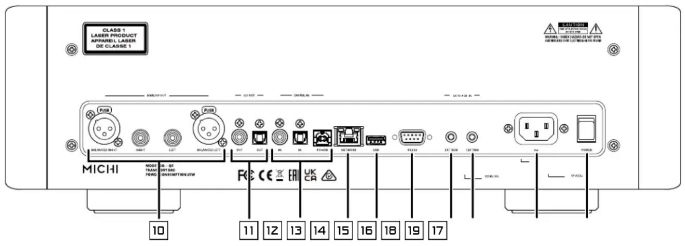
10: Analog Outputs
A pair of standard RCA jacks and XLR balanced connectors supplies an analog output signal.
11: CD Outputs
Supply a digital CD output signal to the source inputs of an audio preamplifier, integrated amplifier, or receiver.
12: Digital Input
Coaxial port: Connect to the coaxial output of your source component.
Optical port: Connect to the optical PCM outputs of your source component.
PC-USB port: Connect to the USB socket of your computer.
13: Network Port
14: USB Power Port
Used for software updates.
15:RS232
Use for integration with automation systems.
16: EXT REM IN Jack
Receive command codes from industry-standard infrared receivers via hard-wired connections.
17: 12V Trigger Connection
Receive a 12V trigger signal.
18: AC Power Input
19: Master Power Switch
Figure 2: RR-RH9 Remote Control Télécommande infrarouge RR-RH9 Fernbedienung RR-RH9 Mando a Distancia RR-RH9
Afstandsbediening RR-RH9 Telecomando RR-RH9 RR-RH9 fjärrkontroll Пульт ДУ RR-RH9
⑥: DISPLAY Button Dims the front display.
(H): RANDOM (REPEAT) Button Play tracks in random order or repeat the disc playback.
(K): PLAY/PAUSE/STOP Button Control the play, pause and stop of the audio. ENTER Button Confirm the unit setting.
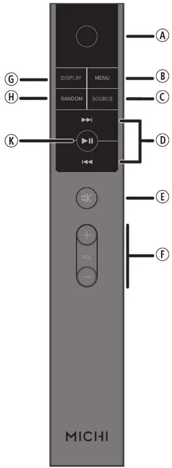
Ⓐ: Power Button Activate the unit or put it into standby mode.
⑧: MENU Button Activates the OSD setup screen on the front display.
©: SOURCE Selects the input signal source.
(D): Track Buttons Select tracks on the disc. Navigation Buttons Access the various menus and operate the unit settings.
E: Mute Button ☒ Mute the audio on a Michi Preamplifier or Integrated Amplifier.
⑤: Volume Buttons Adjust the volume output level on a Michi Preamplifier or Integrated Amplifier.
Figure 3: Analog Output Connections
Branchements des sorties analogiques Anschlussdiagramm (analoge Ausgangsanschlüsse)) Conexiones de Salida Analógicas Analoge uitgangen Collegamenti uscite analogici Anslutningar för analoga utgångar Подсоединение источников сигнала на аналоговые в:
NOTE: Use only 1 connection method.
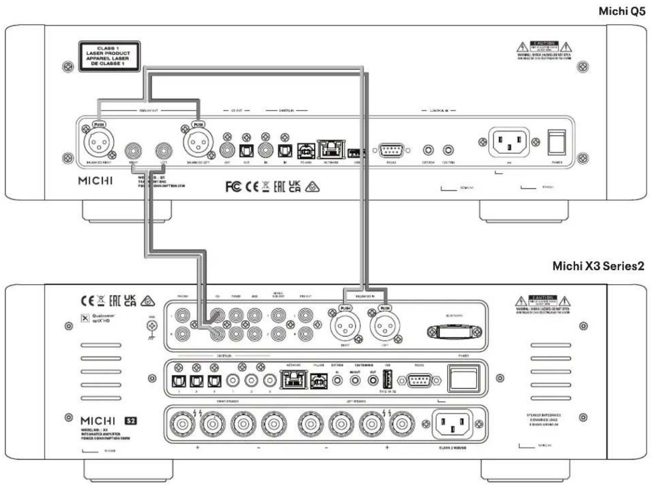
Figure 4: Digital Input and 12 Volt Trigger Connections
Entrées numériques et Branchements des trigger 12 V Anschlussdiagramm (Digitaleingänge, 12V-Trigger) Entrada Digital y Conexiones para Señal de Disparo de 12 Voltios Digitale ingangen en 12V-trigger Collegamenti ingressi digitali e segnali Trigger 12 V Anslutningar för digitala ingångar och 12-volts styrsignaler Цифровой вход и 12-В триггерного
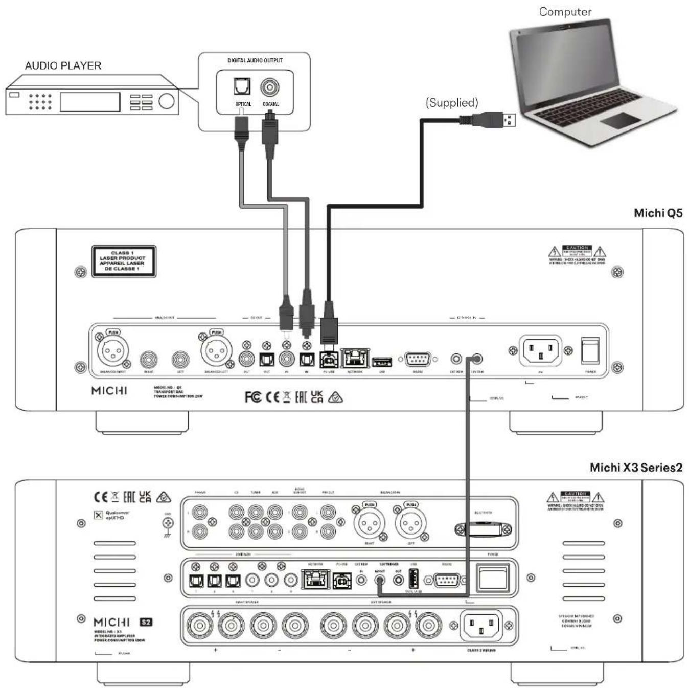
Figure 5: Digital CD Output Connections
When making connections be sure to:
√ Turn off all the components in the system before connecting up any components, including loudspeakers.
√ Turn off all components in the system before changing any of the connections to the system.
It is also recommended that you:
√ Turn the volume control all the way down before the unit is turned on or off.
Remarques importantes
Important Safety Instructions ....3
Figure 1_1: Controls and Connections 4
Figure 1_2: Controls and Connections 5
Figure 2: RR-RH9 Remote Control 6
Figure 3: Analog Inputs and Speaker Output Connections 7
Figure 4: Digital Input and 12 V Trigger Connections 8
Figure 5: Digital CD Output Connections 9
Important notes 10
Getting Started ....11
A Few Precautions 11
Placement 11
Cables 12
The RR-RH9 Remote Control 12
Remote Control Batteries 12
AC Power and Control 12
AC Power Input 18 12
Master Power Switch 12
12V TRIGGER Connection 17 12
Protection Circuit 12
Output Connections....13
Analog Output 13
CD Output 13
Digital Connections 12....13
Digital Inputs 13
PC-USB Input 13
EXT REM IN Jack 10 13
RS232 15 13
Rear USB Port 14 14
Network Connection 13....14
Front Panel Overview....14
Display 14
Disc loader 3 14
Remote Sensor 14
Setup Menu 14
Overview of Buttons and Controls ....14
Main Menu 15
Source Configuration 15
Network Configuration 16
Audio Configuration 16
Display Configuration 17
System Configuration 17
Troubleshooting 18
Power Indicator Is Not Illuminated 18
Fuse Replacement 18
No Sound 18
playable Audio Formats 18
Specifications 18
Getting Started
Thank you for purchasing the Michi Q5 Transport DAC. When used in a high-quality music audio system, your Michi product will provide years of musical enjoyment.
The Q5 is a full featured, high performance component. All aspects of the design have been optimized to retain the full dynamic range and subtle nuances of your music. It has a highly regulated power supply incorporating a Michi custom-designed toroidal power transformer and custom-made slit foil capacitors. This low impedance power supply has ample power reserves, which enables the unit to easily reproduce the most demanding audio signals. This type of design is more expensive to manufacture, but it is better for the music.
The printed circuit boards (PCB) are designed with Symmetrical Circuit Traces. This insures that the precise timing of the music is maintained and faithfully recreated. The unit circuitry use metal film resistors and polystyrene or polypropylene capacitors in important signal paths. All aspects of this design have been examined to ensure the most faithful music reproduction.
The main functions of the unit are easy to install and use. If you have experience with other stereo systems, you shouldn't find anything perplexing. Simply plug in the associated components and enjoy.
A Few Precautions
WARNING: To avoid potential damage to your system, turn off ALL the components in the system when connecting or disconnecting the loudspeakers or any associated components. Do not turn the system components back on until you are sure all the connections are correct and secure.
Please read this manual carefully. In addition to basic installation and operating instructions, it provides valuable information on various system configurations as well as general information that will help you get optimum performance from your system. Please contact your authorized Michi dealer for answers to any questions you might have. In addition, all of us at Michi welcome your questions and comments.
Save the shipping carton and all enclosed packing material for future use. Shipping or moving the unit in anything other than the original packing material may result in severe damage to your audio components.
If included in the box please complete the owner's registration card or register online. Also be sure to keep the original sales receipt. It is your best record of the date of purchase, which you will need in the event warranty service is ever required.
Placement
Like all audio components that handle low-level signals, the unit can be affected by its environment. Avoid placing the unit on top of other components. Also avoid routing audio signal cables near power cords. This will minimize the chance it will pick up hum or interference.
The unit generate heat as part of its normal operation. The heat sinks and ventilation openings in the unit are designed to dissipate this heat. The ventilation slots in the top cover must be open. There should be 50 cm (20 inches) of clearance around the chassis, and reasonable airflow through the installation location, to prevent the unit from overheating.
Remember the weight of the unit when you select an installation location. Make sure that the shelf or cabinet can support it. We recommend installing the unit in furniture designed to house audio components. Such furniture is designed to reduce or suppress vibration which can adversely affect sound quality. Ask your authorized Michi dealer for advice about component furniture and proper installation of audio components.
The unit is supplied with an RR-RH9 remote control and must be placed where the infrared signal from the remote can reach the front panel Remote Sensor.
Cables
Be sure to keep the power cords, digital signal cables and analog audio signal cables in your installation away from each other. This will minimize the chance of the analog audio signal cables picking up noise or interference from the power cords or digital cables. Using only high quality, shielded cables will also help to prevent noise or interference from degrading the sound quality of your system. If you have any questions see your authorized Michi dealer for advice about the best cable to use with your system.
The RR-RH9 Remote Control
Operations with the remote control are described in this manual showing the function keys with encircled letters.
Remote Control Batteries
Two AAA size batteries must be installed before the remote control can be used. To install the batteries, follow the steps as below:
- Lift the ribbon under the remote control and remove it out of the box.
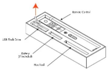
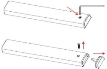
- Remove the screw on the back of the remote using the hex tool (18x86 x3 mm Torx) provided with the remote. Use only the hex tool supplied to avoid damaging the attaching screw.
natural_image
Technical line drawing of two cylindrical mechanical components with red arrows indicating motion or assembly (no text or symbols)- Install the batteries as shown in the illustration in the battery well (Figure 2). Please note there are negative and positive marks shown on the battery cover (Figure 1). Reassemble the battery cover and tighten the screw then test the control for proper operation.
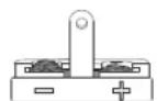
Figure 1
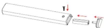
Figure 2
When the batteries become weak the remote control won't operate the device consistently. Installing fresh batteries should eliminate the problem.
NOTE: Use only the tool (18x86 x3 mm Torx) supplied with the unit to remove the screw to avoid damage to the hex screw.
NOTE: Do NOT over-tighten the screw to avoid damage to the screw or remote control.
AC Power and Control
AC Power Input 18
Your unit is configured at the factory for the proper AC line voltage in the country where you purchased it (either 120 volts AC or 230 volts AC with a line frequency of either 50 Hz or 60 Hz). The AC line configuration is noted on a decal on the back panel.
NOTE: Should you move your unit to another country, it is possible to reconfigure your unit for use on a different line voltage. Do not attempt to perform this conversion yourself. Opening the enclosure of the unit exposes you to dangerous voltages. Consult a qualified service person or the Michi factory service department for information.
NOTE: Some products are intended for sale in more than one country and as such are supplied with more than one AC cord. Please only use the one appropriate for your country/region.
Because of its relatively high power rating, the unit can draw considerable current. Therefore, it should be plugged directly into a polarized wall outlet using the supplied cable or other high current compatible cable as recommended by your authorized Michi dealer. Do not use an extension cord.
If you are going to be away from home for an extended period of time such as a month-long vacation, it is a sensible precaution to unplug your unit (as well as other audio and video components) while you are away.
Master Power Switch 19
The large rocker switch on the rear panel is a master power switch. When it is in the OFF position, power to the unit is completely off. When it is in the ON position, the front panel Power button and remote control Power button can be used to activate the unit or put it into standby mode.
12V TRIGGER Connection 17
See Figure 4
The unit can be activated by a 12 volt trigger signal. The trigger input accepts any control signal (AC or DC) ranging from 3 volts to 30 volts. When a cable is connected to the 12V Trigger input and a trigger signal is present, the unit is activated. When the trigger signal is turned off, the unit goes into standby mode. The front panel power indicator will remain illuminated, but the display goes dark and the unit will not operate.
NOTE: When using the 12V Trigger feature, leave the POWER button in the ON position.
Protection Circuit
The unit has both thermal and over-current protection circuitry that protects the unit against damage in the event of extreme or faulty operating conditions. The protection circuits are independent of the audio signal and have no impact on sonic performance. Instead, the protection circuits monitor the
temperature of the output devices and shut down the unit if temperatures exceed safe limits.
Most likely, you will never see this protection circuitry in action. However, should a faulty condition arise, the unit will stop playing and Power LED on the front panel will be red.
If this happens, turn the unit off. Let it cool down for several minutes, and attempt to identify and correct the problem that caused the protection circuitry to engage. When you turn the unit back on, the protection circuit will automatically reset and the Power LED should be white, indicating that the unit is operating normally.
In most cases, the protection circuitry activates because of a fault condition such as shorted speaker wires, or inadequate ventilation leading to an overheating condition. In very rare cases, highly reactive or extremely low impedance speaker loads could cause the protection circuit to engage.
If the protection circuitry triggers repeatedly and you are unable to isolate and correct the faulty condition, contact your authorized Michi dealer for assistance in troubleshooting.
Output Connections
The built in D/A converter provides digital to analog conversion allowing connection using either XLR Balanced or RCA analog output connectors.
NOTE: To prevent loud noises that could damage your speakers, turn off all the system components when you make any signal connections.
Analog Outputs 10
See Figure 3
A pair of standard RCA jacks and XLR balanced connectors supplies an analog output signal from the unit to the source inputs of an audio preamplifier, integrated amplifier, or receiver. You should choose only one method of analog connection from the unit. Do not connect both the RCA and XLR at the same time.
Select high quality audio interconnect cables. Connect the left and right channel outputs of the unit to the corresponding inputs on the preamplifier or other component.
CD Outputs 11
See Figure 5
There is one set of digital outputs providing a digital output signal from the unit when CD is selected as the audio source. Connect the CD OUT coax or optical output to the digital input on the outboard D/A converters or digital processors.
NOTE: Only the CD audio is available on the Digital Output. Other digital source inputs are not available on these connectors.
Digital Input Connections 12
See Figure 4
Digital Input
There is one set of digital inputs labeled COAXIAL and OPTICAL allowing you to connect the PCM outputs of your source component. The digital signals will be decoded and played by the unit. The unit is capable of decoding PCM signals up to 24 bit, 192kHz.
PC-USB Input
Connect this input using a PC-USB cable to the USB socket of your computer or audio streamer.
The unit supports USB Audio Class 2.0 modes. To take advantage of USB Audio Class 2.0 audio playback supporting up to 384 kHz sampling rates you will need to install the Windows driver supplied on the USB Flash Drive included with the unit.
Many audio playback applications do not support 384 kHz sampling rate. Please confirm your audio player supports a 384 kHz audio and you have 384 kHz audio files to properly playback this sample rate. Also, you may need to configure the audio driver in your PC to output 384 kHz or your computer may "down sample" to a lower audio sample rate. For more information please refer to your audio player or operating system information.
The unit has been certified as Roon Tested and compatible with Roon software via PC-USB.
roon TESTED
Being Roon Tested means that Rotel and Roon have collaborated to ensure you have the best experience using Roon software and the unit together, so you can just enjoy the music.
For the best user experience it is suggested to use USB Audio Class 2.0 when using Roon.
NOTE: USB Audio Class 2.0 requires installation of the Windows PC driver on the USB Flash Drive included with the unit.
NOTE: MAC computers do not require a driver to support PC-USB 1.0 or 2.0 audio.
NOTE: Upon successful installation of the driver, you may need to select the Michi audio driver from the audio/speaker setup of your computer.
NOTE: The unit supports both DSD and DOP audio playback in 1X, 2X and 4X formats. Consult your audio player to confirm proper operation for playback of these audio formats.
NOTE: Support for MQA and MQA Studio requires USB Audio Class 2.0. Please select USB Audio 2.0 to support MQA.
EXT REM IN Jack 16
This 3.5mm mini-jack receives command codes from industry-standard infrared receivers via hard-wired connections. This feature could prove useful when the unit is installed in a cabinet and the front-panel sensor is blocked. Consult your authorized Michi dealer for information on these external repeaters and the proper wiring of a jack to fit the mini-jack receptacle.
RS232 15
The unit can be controlled via RS232 for integration with automation systems. The RS232 input accepts a standard straight DB-9 Male-to-Female cable.
For additional information on the connections, software, and operating codes for RS232 control of the unit, contact your authorized Michi dealer.
Rear USB Port 14
The rear USB port is only used for software updates.
NOTE: This port does not allow playback of audio.
Network Connection 13
The unit can be attached to a network using the rear panel NETWORK socket. The NETWORK configurations allow both STATIC and DHCP IP addressing. See the Network Setup section of this manual under Setup Menu for IP address configuration information.
The NETWORK connection allows software updates to be downloaded from the Internet. The NETWORK connection also allows IP control for integration with automation systems.
When connected to a network CD album artwork may be available to display on the front panel screen.
For additional information on the IP control please contact your authorized Michi dealer.
Front Panel Overview
The following is a brief overview of the controls and features on the front panel of the unit.
Display 1
The front panel display shows the status of the unit, activation of special features, album artwork, and track/time information for the disc being played. The display can be dimmed using the setup menu or the IR remote controller. See the Display Configuration section of this manual for details.
Disc loader 3
The CD loader located on the top of the unit, accepts a compact disc. Take out the disc cover, then put in the CD disc and put back the disc cover. The CD loader accepts standard REDBOOK CDs as well as MP3 files.
Remote Sensor 4
This remote sensor window receives IR commands from the remote control. Please do not block this sensor.
Setup Menu
The Michi unit features the information display to help operate the system. A more comprehensive ON-SCREEN DISPLAY (OSD) menu system is available at any time by pressing the MENU button on the remote. These OSD menus guide you through the configuration and setup of the unit. The settings made in the configuration process are memorized as default settings and need not be made again for normal operation of the unit.
Overview of Buttons and Controls
This section provides a basic overview of the buttons and controls on the remote control. Detailed instructions on the use of these buttons are provided in the more complete operating instructions in the following sections.
Play/Pause/Stop (Enter) Button 6 7 K: After the disc is loaded, press the ▶ II button K on the remote control or the ▶ button 7 on the front panel to start playing the disc. The number of the track being played and the elapsed time will be shown in the display, along with the PLAY indicator. Normally, the disc will start playing with the first track. However, you can select a different track using the Track buttons (see below) before pressing the ▶ II button K or the ▶ button 7 to start playing a different selection.
To temporarily suspend play, press the button Ⓚ on the remote control again. The disc continues to spin and play will be resumed from the current position. The PAUSE indicator will show on in the display. To resume playing the disc, press the Ⓥ again, or press the ▶ button 7.
When the play is suspended for 5 minutes, or the button 5 on the front panel is pressed, or the ▶ II Ⓚ button on the remote control is pressed and held for 4 seconds, the unit will stop playing and the display shows STOP indicator. When the ▶ button Ⓚ or the ▶ button 7 is pressed, the disc begins playing from the first track.
The ▶II button Ⓚ is also used during setup as an "Enter" button to accept a setting value.
Track (Navigating) Buttons 8 9 ①: These buttons are used to select tracks on the disc. When a disc is playing, pressing the TRACK button advances to the beginning of the next track. Pressing the TRACK button returns to the beginning of the previous track. The new track number appears in the display.
These buttons are also used to select a track before pressing the button ☑ on the remote control or the ▶ button 7 on the front panel. These selections are made by continuously pressing the TRACK buttons until the desired track is reached.
The navigation buttons are also used during setup to move through the various menus and value options.
Power ☐ A: The Power button on the front panel and on the remote control activate or deactivate the unit. There is an LED light in the middle of the Power button on the remote control, which will be illuminated when you pick up the remote control. To power on the unit, the rear panel master POWER switch must be in the ON position for the front panel and the remote standby function to operate.
Power On - To power on the unit push and release the Power button ☐ on the front panel or Ⓐ the IR remote control.
Power Off/Standby - To power off the unit to standby push and release the front panel Power button 2 or PUSH-HOLD the remote control Power button A for 1.5 seconds.
NOTE: All Michi products will respond to the same Power On and Off commands to simplify the power control when multiple products are installed. To control the power using the IR remote follow the instructions above and point the remote control at the Michi products. If a unit does not respond to a power on or off from the IR remote simply PUSH or PUSH-HOLD the power button again to resend the desired command.
MENU Ⓑ: The MENU button activates the OSD setup screen on the front display. Push the MENU button again to move to the previous setup menu as a "back" key or exit setup menu if on the first level of setup menu.
SOURCE 5 C: The SOURCE 5 button on the front panel and the SOURCE ⑤ button on the remote control selects the input signal source. From the front panel press the SOURCE button 5 to access the source menu and press the SOURCE button 5 repeatedly to toggle through the sources. After 3 second of no action the listed source will be selected as the active source.
On the IR remote push the SOURCE button and navigate to the desired source using the ◀◀ ▶▶(D) buttons and push the ▶II (K) button to activate the source.
NOTE: Only sources that are configured as ACTIVE in the setup menu will be displayed as options.
DISPLAY ⑥: Dims the front display. To dim the display PUSH-HOLD the DISPLAY ⑥ button on the remote control for 3 seconds. To turn on the display to the level of brightness configured in the setup menu push and release the DISPLAY ⑥ button.
NOTE: The DISPLAY button is common for all Michi models. To Dim or enable the display PUSH or PUSH-HOLD the button and point to the Michi products. If a unit does not respond to a DISPLAY command simply send the command again using a PUSH or PUSH-HOLD.
RANDOM Ⓗ: This instructs the unit to play tracks from the entire disc in a random order. Once all of the selections have been played once, the disc will stop playing. When enabled the RANDOM indicator will be displayed on the front panel.
REPEAT Ⓗ: Press and hold the RANDOM button for 3 seconds, the unit will repeat the entire disc continuously until the feature is cancelled by pressing and holding the RANDOM button for 3 seconds again. When enabled the REPEAT indicator will be displayed on the front panel.
☒ Button E: Push the button once to mute the audio on an attached Michi Preamplifier or Integrated Amplifier. There is no action on the unit when using the MUTE button. Press the button again to restore the previous volume level.
VOL+/- Buttons: The VOLUME +/- buttons on the remote adjust the master VOLUME on an attached Michi Preamplifier or Integrated Amplifier. There is no action on the unit when using the volume control buttons.
Main Menu
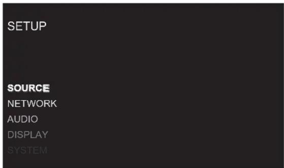
The SETUP menu provides access to OSD screens for various configuration options. The Setup menu is reached by pressing the MENU Ⓑ button on the remote. To select the desired menu, move the highlight using the ▶◀ ▶▶ I D buttons and press the ▶II K button on the remote control. Press the MENU Ⓑ button again to return to the previous menu or select "EXIT" on the OSD to end setup and return to normal operation.
Source Configuration
| SETUP | ||
| SOURCE | Input | COMPACT DISC |
| Name | COAX | |
| Enabled | OPT | |
| Back | PC-USB | |
A key step in setting up the unit, is to configure each source input using the Source Setup screens. Configuring the inputs allows you to set defaults for a number of settings including custom labels that appear in the displays when a source is selected, enable or disable the source and other options.
This Source menu in the Setup menu, provides the following options, selected by placing the highlight on the desired line using the ▶◀ ▶▶① buttons and pressing the ▶||① button. This action displays the right side options allowing changes. Change the options using the ▶◀ ▶▶① buttons and press the ▶||① button to confirm.
Input: Changing this input allows you to select a specific input for configuring. (COMPACT DISC, COAX, OPT, PC-USB)
Name: The name of the source can be customized. For example Aux 1 can be named "TV" for easier reference. The default NAME is the same as the SOURCE. Place the highlight on this option and use the ▶▶▶▶▶▶▶▶▶▶▶▶▶▶▶▶▶▶▶▶▶▶▶▶▶▶▶▶▶▶▶▶▶▶▶▶▶▶▶▶▶▶▶▶▶▶▶▶▶▶▶▶▶▶▶▶▶▶▶▶▶▶▶▶▶▶▶▶▶▶▶▶▶▶▶▶▶▶▶▶▶▶▶▶▶▶▶▶▶▶▶▶▶▶▶▶▶▶▶▶▶>
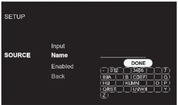
- Pressthe A◀◀ ▶▶▶I⑭ buttons on the remote control to change the first letter, scrolling through the list of available characters.
- Pressthe ▶II Ⓚ button on the remote control to confirm that letter and move to the next position.
- Repeat steps 1 and 2 until all ten characters have been completed. The final press of the ▶■K button saves the new name. You can select the "DONE" button on the OSD to confirm if you have less than ten characters to enter.
Enabled: Allows a source input to be enabled and appear in the list of source input options when using the source selection on the front panel or IR remote control. Unused sources should be set to disabled by selecting the "No" option.
Options include: Yes(Default), No.
Press the MENU button Ⓑ on the remote control to exit the setup menu or select "Back" on the OSD to return to the main menu.
Network Configuration
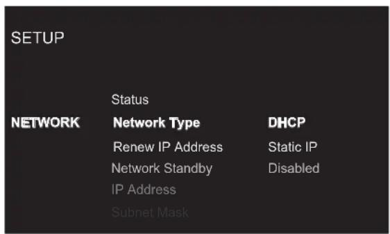
This NETWORK menu in the SETUP menu, provides the following options, selected by placing the highlight on the desired line using the ◀◀/▶▶I Ⓓ buttons and pressing the ▶||K button. This action displays the right side options allowing changes. Change the options using the ◀◀ ▶▶I Ⓓ buttons and press the ▶||K button to confirm.
Status: If the network is properly configured and attached to the network then "Connected" will be displayed. If the network is not properly configured or not connected to a network, "Disconnected" will be displayed.
Network Type: In most systems, set the IP ADDRESS MODE to DHCP. This setting will allow your router to assign an IP address to the unit automatically. If your network uses fixed IP addresses, set the IP ADDRESS MODE to Static. To disable the IP connection set this option to DISABLED.
Options include: DHCP (Default), Static IP, Disabled.
Renew IP Address: Disabled if Network Type is Static or Disabled. If Network Type is DHCP then select Yes and press the ▶II Ⓚ button to renew the IP address.
Network Standby: When set to Enabled the unit will maintain the Ethernet IP connection even in Standby Mode allowing the unit to be powered on via IP. If Disabled the unit will not power on from the IP connection and must use either the front panel, IR remote or RS232 to power on the unit.
Options Include: Disabled (Default), Enabled
NOTE: When Network Standby is enabled the unit will consume additional power.
IP Address/Subnet Mask/Gateway/DNS: Disabled if Network Type is DHCP or Disabled. If STATIC mode is selected you must configure all settings for the network including IP Address, Subnet Mask, Gateway and DNS Server. Press the ▶■K button to activate the first digit in the line you want to change, then use the ◀◀/▶▶ID buttons to adjust the values and press the ▶■K button to cycle to the next digit. When the proper IP information is configured press the ▶■K button to move the cursor back to the previous menu and accept the settings. After entering the STATIC IP address information the network will be tested and connection status reported.
NOTE: For more information regarding network connection please contact your authorized Michi dealer.
NOTE: A network connection is not required for the unit to operate.
Press the MENU Ⓑ button on the remote control to exit the setup menu or select Back to return to the main menu.
Audio Configuration
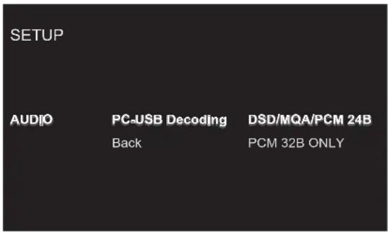
This AUDIO menu in the SETUP menu, provides the following options, selected by placing the highlight on the desired line using the ▶◀ ▶▶① buttons and pressing the ▶||① button. This action displays the right side options allowing changes. Change the options using the ▶◀ ▶▶① buttons and press the ▶||① button to confirm.
PC-USB Decoding: Change PC-USB Audio mode to support DSD, MQA and PCM Audio up to 24bits or PCM Audio Only up to 32bits. When PCM 32B Only is selected DSD/MQA audio is not supported. To playback DSD/MQA the DSD/MQA/PCM 24B option must be selected.
Options include: DSD/MQA/PCM 24B (Default), PCM 32B Only.
Press the MENU Ⓑ button on the remote control to exit the setup menu or select "Back" on the OSD to return to the main menu.
Display Configuration
| SETUP | ||
| DISPLAY | BrightnessHigh | High |
| Temporary Display | Medium High | |
| LED Brightness | Medium | |
| Top LED Mode | Medium Low | |
| Back | Low | |
This DISPLAY menu in the SETUP menu, provides the following options, selected by placing the highlight on the desired line using the ▶◀ ▶▶①D buttons and pressing the ▶||①K button. This action displays the right side options allowing changes. Change the options using the ▶◀ ▶▶①D buttons and press the ▶||①K button to confirm.
Brightness: This function sets the brightness of the front display. The setting is activated during normal operation by a PUSH RELEASE of the DISPLAY button ⑥ on the remote control. The OSD will always activate at the most bright level regardless of the Brightness setting to ensure the unit configuration options can easily be accessed and modified.
Options include: High (Default), Medium High, Medium, Medium Low, Low.
NOTE: To dim the front display PUSH-HOLD the DISPLAY⑥ button on the remote control for 3 seconds.
Temporary Display: This function allows the front display to temporarily show changes to the unit for the time-out period before the display turns off again. An example would be to turn on the display to show changes to the source or volume levels then turn off the display after the time-out period expires. To disable the temporary display and have the unit display always on set this function to Disable.
Options include: Disabled (Default), 5 seconds, 10 seconds, 15 seconds.
LED Brightness: Sets the brightness of the ON level of the front panel Power LED.
Options include: High (Default), Medium High, Medium, Medium Low, Low.
Top LED Mode: When set to Enabled mode, the LED ring inside the CD mechanism will be illuminated when the CD cover is removed and off when the cover is replaced. When the CD is playing, the breathing LED ring offers a soothing, rhythmic visual effect that reflects the ongoing playback. To disable the LED ring, set to Disable option. The LED ring will always be illuminated when the unit is powered on.
Options include: Enabled (Default), Disabled.
Press the MENU Ⓑ button on the remote control to exit the setup menu or select "Back" on the OSD to return to the main menu.
System Configuration
| SETUP | ||
| PC-USB Version | ||
| Software Version | Disabled | |
| SYSTEM | Auto Power Off | 20 MIns |
| Software Update | 1 Hour | |
| Factory Default | 2 Hours | |
| Back | 5 Hours | |
| 12 Hours | ||
This SYSTEM menu in the SETUP menu, provides the following options, selected by placing the highlight on the desired line using the ▶◀ ▶▶① buttons and pressing the ▶||① button. This action displays the right side options allowing changes. Change the options using the ▶◀ ▶▶① buttons and press the ▶||① button to confirm.
CD Version: This shows the current loaded software version for the CD mechanism.
PC-USB Version: This shows the current loaded software version for the PC-USB processor.
Software Version: This shows the current software version loaded into the unit.
Auto Power Off: Set the amount of time the units stays powered on when there is no audio signal. The unit will automatically go to standby mode if audio is not detected for the specified timer period. Default: 20 Mins.
Options include: Disabled, 20 Mins, 1 Hour, 2 Hours, 5 Hours, 12 Hours.
Software Update: Select the desired update method to update the unit.
Options include: No (Default), USB, Internet.
Factory Default: This option sets the unit back to the original setting as when it left the factory. All user settings will be erased.
NOTE: Use caution when resetting the unit to factory defaults as all user configured options will be erased and reset to the original factory settings.
Press the MENU Ⓑ button on the remote control to exit the setup menu or select "Back" on the OSD to return to the main menu.
Troubleshooting
Most difficulties in audio systems are the result of incorrect connections, or improper control settings. If you encounter problems, isolate the area of the difficulty, check the control settings, determine the cause of the fault and make the necessary changes. If you are unable to get sound from the unit, refer to the suggestions for the following conditions:
Power Indicator Is Not Illuminated
The front power indication will be illuminated anytime the unit is connected to AC power and the rear power switch is set to the ON position. The indication will be RED for standby mode and WHITE in normal operation. If the indication is not illuminated, test the power outlet with another electrical device, such as a lamp. Be sure the power outlet being used is not controlled by a switch that has been turned off. And check all AC power including the rear power switch to ensure the unit is receiving power.
Fuse Replacement
If another electrical device works when plugged into the power outlet, but the Power Indicator still will not illuminate when the unit is plugged into the outlet, it indicates that the internal power fuse may have blown. If you believe this has happened, contact your authorized Michi dealer to get the fuse replaced.
No Sound
Check the signal source to see if it is functioning properly. Make sure the cables from the signal source to the unit inputs are connected properly.
playable Audio Formats
PC-USB
| Format | Notes |
| Format determined by the Media Player/Server software that you use. | Any supported format by the PC softwarePCM Audio:44.1k, 48k, 88.2k, 96k, 176.4k, 192k, 384k(16 bit, 24 bit and 32 bit)DSD64, DSD128 and DSD256MQA, MQA StudioRoon Tested |
Coax/Optical
| Format | Notes |
| SPDIF LPCM | 44.1k, 48k, 88.2k, 96k, 176.4k, 192k16 bit, 24 bit |
'MQA' or 'MQA.' indicates that the product is decoding and playing an MQA stream or file, and denotes provenance to ensure that the sound is identical to that of the source material. 'MQA.' indicates it is playing an MQA Studio file, which has either been approved in the studio by the artist/ producer or has been verified by the copyright owner.
'OFS' confirms that the product is receiving a decoded MQA stream or file and is performing the final unfold of the stream or file and displays the original sample rate of the master.
Specifications
| Total Harmonic Distortion | < 0.0006% |
| Intermodulation Distortion | < 0.002% |
| Frequency Response: Frequency Response: 20 Hz - 20kHz, +0,- 0.1 dB | |
| 10 Hz - 70kHz, +0,- 3 dB | |
| Channel Balance Channel Balance ± 0.5 dB | |
| Channel Separation Channel Separation | >104 dB @ 10 kHz |
| Signal to Noise Ratio (IHF A weighted) | >115 dB |
| Dynamic Range | >99 dB |
| Input Sensitivity / Impedance | 0 dBFS / 75 ohms |
| Digital to Analog Converter | ESS 32Bit/768kHz DAC |
| CD Output | Digital output(16-Bit/44.1kHz, 0 dBFS) |
| Analog Output Level | |
| Unbalanced (RCA)/Impedance | 2.3V / 100 ohms |
| Balanced (XLR)/Impedance | 4.9V / 4K ohms |
| Coaxial/Optical Digital Signals | SPDIF LPCM(up to 24-bit / 192kHz) |
| PC-USB | USB Audio Class 2.0(up to 32-bit / 384kHz)**Driver installation requiredsupport DSD (up to 4X, 11.2MHz/s)and DoP (up to 2X, 5.6M)support MQA and MQA Studio(up to 24-bit / 384kHz)Roon Tested support |
| Power Requirements: | |
| USA: | 120 volts, 60 Hz |
| EC: | 230 volts, 50 Hz |
| Power Consumption | 25 watts |
| Standby Power Consumption | < 0.5 watts |
| Dimensions (W x H x D) | 485 x 150 x 452 mm(19 x 6 x 17 ^3/_4 ins.) |
| Front Panel Height | 132 mm, 5^1/_4 ins |
| Weight (net) | 23.5 kg, 51.8 lbs. |
All specifications are accurate at the time of printing.
Michi reserves the right to make improvements without notice.
MICHI
The Rotel Co. Ltd.
Tachikawa Bldg. 1F.,
2-11-4, Nakane, Meguro-ku,
Tokyo, 152-0031
Japan
Email: sales@rotel.com
www.rotel.com
- Michi Q5
- Pin Assignments
- IMPORTANT FOR LASER PRODUCTS
- CLASS 1 LASER PRODUCT
- WARNING!
- Important Safety Instructions
- Notice
- FCC Information
- Caution
- Remarques importantes
- Getting Started
- A Few Precautions
- Placement
- Cables
- The RR-RH9 Remote Control
- Remote Control Batteries
- AC Power and Control
- AC Power Input 18
- Master Power Switch 19
- 12V TRIGGER Connection 17
- See Figure 4
- Protection Circuit
- Output Connections
- Analog Outputs 10
- CD Outputs 11
- Digital Input Connections 12
- Digital Input
- PC-USB Input
- roon TESTED
- EXT REM IN Jack 16
- RS232 15
- Rear USB Port 14
- Network Connection 13
- Front Panel Overview
- Display 1
- Disc loader 3
- Remote Sensor 4
- Setup Menu
- Overview of Buttons and Controls
- Main Menu
- Source Configuration
- Network Configuration
- Audio Configuration
- Troubleshooting
- Power Indicator Is Not Illuminated
- Fuse Replacement
- No Sound
- MICHI
- The Rotel Co. Ltd.
Brand : ROTEL
Model : Michi Q5
Category : CD Player