T 394 - Thermometer PCE Instruments - Free user manual and instructions
Find the device manual for free T 394 PCE Instruments in PDF.


| Product Type | Temperature Data Logger with 4-channel thermocouple input |
| Model | PCE-T 394 |
| Measurement Range (K-type) | -200 ... 1370 °C (-328 ... 2498 °F) |
| Measurement Range (J-type) | -210 ... 1100 °C (-346 ... 2012 °F) |
| Accuracy | ±(0.2 % of Rd + 1 °C) above -100 °C; ±(0.5 % of Rd + 2 °C) below -100 °C |
| Resolution | 0.1 °C/°F/K (<1000), 1 °C/°F/K (>1000) |
| Data Update Rate | 500 ms |
| Data Logger Capacity | 32,000 sets of measured values |
| Interfaces | Micro-USB for PC connection |
| Power Supply | 3.7 V Li-Ion rechargeable battery, charged via USB (5 V DC) |
| Auto Power Off | After 20 minutes of inactivity (adjustable or disabled) |
| Dimensions (Meter) | 162 x 88 x 32 mm (6.38 x 3.46 x 1.26") |
| Dimensions (Sensor) | 102 x 60 x 25 mm (4.01 x 2.36 x 0.98") |
| Weight | Approx. 246 g (0.542 lbs) |
| Operating Conditions | -10 ... 50 °C, <80 % RH |
| Storage Conditions | -20 ... 50 °C, <80 % RH |
| Included Accessories | 1x temperature data logger, 1x USB cable, 1x PC software, 1x service bag, 1x user manual |
| Maintenance & Cleaning | Clean with damp soft cloth; do not use abrasives or solvents |
| Safety Notes | Only use as described; avoid extreme conditions; do not open case except by qualified personnel |
| Key Functions | MAX/MIN/AVG, Hold, Recording, Differential (T1-T2, T3-T4), Thermocouple type selection (K/J) |
Frequently Asked Questions - T 394 PCE Instruments
User questions about T 394 PCE Instruments
0 question about this device. Answer the ones you know or ask your own.
Ask a new question about this device
Download the instructions for your Thermometer in PDF format for free! Find your manual T 394 - PCE Instruments and take your electronic device back in hand. On this page are published all the documents necessary for the use of your device. T 394 by PCE Instruments.
USER MANUAL T 394 PCE Instruments
User Manual
PCE-T 394 Temperature Data Logger
User manuals in various languages (français, italiano, español, português, nederlands, türk, polski, русский, 中文) can be found by using our product search on: www.pce-instruments.com
Last change: 13 March 2024
v1.0
Contents
1 Safety notes.... 1
2 Specifications.... 2
3 Delivery scope....2
4 Device description .... 3
4.1 Key description ....3
4.2 Display ....3
5 Operating instructions....4
5.1 Switch the meter on/off 4
5.2 Set the type of thermocouple....4
5.3 Connect the probe to meter....4
5.4 Measurement....4
5.5 MAX, MIN & AVG value....4
5.6 Hold data....5
5.7 Recording mode....5
5.8 Data recording and software installation .... 5
5.9 Auto Power Off....5
6 Settings....6
6.1 Enter and exit setup....6
6.2 Set the type of thermocouple probe 6
6.3 Set the date....6
6.4 Set the time....7
6.5 Setting the interval for data logging....7
6.6 Setting the compensation....7
7 Calibration 8
7.1 Preparation for calibration....8
7.2 Cold-junction compensation calibration....8
7.3 AD value calibration (only to be carried out by PCE Instruments) 8
8 Maintenance and cleaning....9
8.1 Cleaning and storage....9
8.2 Charging the battery 9
9 Contact....9
10 Disposal 9
1 Safety notes
Please read this manual carefully and completely before you use the device for the first time. The device may only be used by qualified personnel and repaired by PCE Instruments personnel. Damage or injuries caused by non-observance of the manual are excluded from our liability and not covered by our warranty.
- The device must only be used as described in this instruction manual. If used otherwise, this can cause dangerous situations for the user and damage to the meter.
- The instrument may only be used if the environmental conditions (temperature, relative humidity, ...) are within the ranges stated in the technical specifications. Do not expose the device to extreme temperatures, direct sunlight, extreme humidity or moisture.
- Do not expose the device to shocks or strong vibrations.
• The case should only be opened by qualified PCE Instruments personnel.
- Never use the instrument when your hands are wet.
- You must not make any technical changes to the device.
- The appliance should only be cleaned with a damp cloth. Use only pH-neutral cleaner, no abrasives or solvents.
• The device must only be used with accessories from PCE Instruments or equivalent.
- Before each use, inspect the case for visible damage. If any damage is visible, do not use the device.
- Do not use the instrument in explosive atmospheres.
- The measurement range as stated in the specifications must not be exceeded under any circumstances.
- Non-observance of the safety notes can cause damage to the device and injuries to the user.
We do not assume liability for printing errors or any other mistakes in this manual.
We expressly point to our general guarantee terms which can be found in our general terms of business.
2 Specifications
| K-type thermocouple measurement range | -200 ... 1370 °C (-328 ... 2498 °F) |
| J-type thermocouple measurement range | -210 ... 1100 °C (-346 ... 2012 °F) |
| Accuracy | ±(0.2 % of Rd+1 °C) above -100 °C ±(0.5 % of Rd +2 °C) below -100 °C |
| Resolution | 0.1 °C/°F/K <1000, 1°C/°F/K >1000 |
| Data update rate | 500 ms |
| Auto power off | after 20 minutes of inactivity |
| Battery level indicator | flashes when the battery voltage is too low |
| Data logger | 32,000 sets of measured values |
| Power supply | 3.7 V Li-Ion battery |
| Operating conditions | -10 ... 50 °C / <80 % RH |
| Storage conditions | -20 ... 50 °C / <80 % RH |
| Dimensions | Meter: 162 x 88 x 32 mm (6.38 x 3.46 x 1.26") Sensor: 102 x 60 x 25 mm (4.01 x 2.36 x 0.98") |
| Weight | approx. 246 g (0.542 lbs) |
* The probe provided with the instrument is a K-type thermocouple and the applicable temperature range is -50\~200 °C.
* To avoid interference with the instrument and causing wrong readings, please do not shake the thermocouple probes during temperature measurement.
3 Delivery scope
1 x temperature data logger PCE-T 394
1 x USB cable
1 x PC software
1 x service bag
1 x user manual
4 Device description
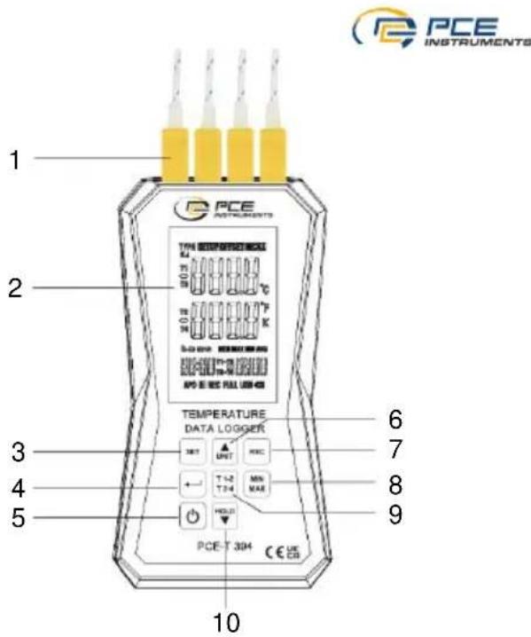
4.1 Key description
- Thermocouple probes T1\~T4
- LC Display
- Setup key
- Enter (confirm) key
- ON/OFF key
- Temperature unit and arrow up key
- Record key
- MAX/MIN key
- Channel T1/2, T3/4 & differential value switching key
- Data hold & arrow down key
Note:
The micro-USB socket is located at the bottom of the meter.
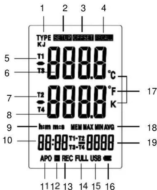
4.2 Display
- Type of thermocouple (K or J)
- Enter setup menu
- Offset indicator
- Reading data from memory
- Channel T1/T3 indicator
- Digital display for channel T1/T3
- Channel T2/T4 indicator
- Digital display for channel T2/T4
- Time setting indication
- Auto ranging indicator
- Automatic power off
- Freeze data
- Data recording icon
- Memory-full indicator
- USB icon
- Battery icon
- Temperature unit
- MAX, MIN & AVG indicator
- T1/T2/T3/T4 reading
5 Operating instructions
5.1 Switch the meter on/off
Press and release the ⏻ key to turn on the temperature data logger and press and hold the same key for 3 seconds to turn it off.
5.2 Set the type of thermocouple
Set the type of thermocouple you want to use. As default, the K-type thermocouple is used.
-
Press and hold the key for 3 s to enter setup mode, then the selection window for the thermocouple types (K or J) appears.
-
Press the key, the type of thermocouple icon will flash on LCD.
-
Press the ▲ or ▼ key to select the correct type of thermocouple and press the key to confirm.
5.3 Connect the probe to meter
Connect the correct thermocouple probe to the T1, T2, T3, T4 input jacks at the top of the temperature data logger.
The North American ANSI colour codes of the thermocouples are:
| Type | K | J |
| Color | Yellow | Black |
5.4 Measurement
The first reading will be displayed in about 1 second. It will display“----” if the thermocouple probe is not plugged into any one channel.
Leave the temperature data logger in the environment to be tested for some time to get stable readings.
Press and release the Key to select the temperature unit you prefer.
Press the key. The readings of the channels T3 & T4 will be displayed as the main reading and the DIF value (T3-T4) will be displayed as the sub-reading. When you press the key again, the readings of the channels T1 & T2 will be displayed as the main reading and the DIF value (T1-T2) will be displayed as the sub-reading.
5.5 MAX, MIN & AVG value
Press the key once to enter MAX/MIN/AVG mode. The maximum value, minimum value (MIN) and average value (AVG) of T1 will appear successively.
Press the key to switch the MAX/MIN/AVG value of T1-T2 and T3-T4 successively.
Press the KEY for 3 seconds until the MAX & MIN icon disappears to exit MAX/MIN mode.
Note:
The functions of the key and Auto Power Off will be disabled when MAX/MIN mode is active.
5.6 Hold data
Press the HOLD Key. The digital reading is held and the HOLD icon appears on the LCD.
Press the key to switch between the readings of T1 & T2 or T3 & T4 at the main display and the values of T1-T2 or T3-T4 at the sub-display.
Press the HOLD Key again to return to normal operation.
5.7 Recording mode
The PCE-T 394 has a data logger function. It records max. 32000 groups of data. The recorded data can be read out via a PC.
-
Start the recording: As default, recording is started by pressing a key. You can change the start mode setting via the software. Please refer to the PCE software manual for details.
-
Set the interval: Before starting to record, set the sampling interval of the PCE-T 394 as described under 6.5 Setting the interval for data.
-
Press the REC key to start recording, press the key again for 3 seconds to stop recording.
-
When the set number of records is reached, a FULL icon will be displayed at the bottom of the LCD screen.
-
Data can be deleted automatically by re-setting the recording elements.
-
Read out the data: After recording, you can connect the data logger to a PC via the USB port and with the PCE software, you can read out and analyse the data accordingly. Please refer to the PCE software manual for details.
Note:
When the temperature data logger is at low battery, the recording function does not work and data cannot be deleted. If you need to record for a long time, fully charge the battery or use the AC/DC power adaptor for power supply.
Note:
When the instrument is in recording mode, unplug the probe and the LCD screen will display ERR.
5.8 Data recording and software installation
This temperature data logger is able to record data in its internal memory. Before you can record data, you need to install the PCE software on your PC. The latest version of this software and detailed instructions on how to install and use it can be found at https://www.pce-instruments.com. A CD with the software is included for your convenience but we recommend downloading the latest version at the PCE Instruments website.
To set up the meter for recording, connect it to a PC via the micro USB port.
5.9 Auto Power Off
The APO function is set to ON by default. To turn off the APO function, press the key lightly. To extend the battery life, the temperature data logger will automatically turn off after about 10 minutes when not in use.
In recording mode or when the meter is connected via USB, the APO function is automatically disabled until the memory is full or the set number of records is reached.
6 Settings
With the key, you can set the time and date, select the type of thermocouple and change the recording interval and compensation.
6.1 Enter and exit setup
Press and hold the SET key for about 3 s to enter the setup menu. The SETUP icon will appear on the LCD. Press and hold the SET or key for about 3 s to exit the setup menu. Under setup, the button functions are as below:
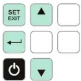
Press the ▲ or ▼ key to select the options and then press the ← key to confirm. The setup function is not available in MAX/MIN/AVG mode.
6.2 Set the type of thermocouple probe
Press and hold the key for 3 s to enter setup mode, then the selection window for the type of thermocouple (K or J) appears.
Press the key. The type of thermocouple icon will flash on LCD.
Press the ▲ or ▼ key to select the correct type of thermocouple and press to confirm.
6.3 Set the date
- Enter setup mode and press ▲ or ▼ until dRtE and PPPP are displayed.
- Press ← to set the year. "2018" will flash at the bottom, on the left.
- Press ▲ or ▼ until the year display is correct, then press ← to confirm.
- Press ▼ again. dAte and nn are shown on the main display. Press the ← key to select the month setting. The number will flash at the bottom, on the left.
- Press of to change the month, then press to confirm.
- Press the ▼ key again. dd will be shown on main display. Press ← to select the date setting. The number will flash at the bottom, on the left.
- Press o▲ to change the date. Then press to confirm.
6.4 Set the time
- Enter setup mode and press the ▲ or ▼ key to display E I&E and HH.
- Press the key to select the hour. The number will flash at the bottom, on the left.
- Press o▲ to change the hour and press to confirm.
- Press ▼ again. E I&E and nn are shown on the main display. Press the ← button to select the minute. The number will flash at the bottom, on the left.
- Press ▲ or ▼ to change the minute and then press the ← key to confirm.
- Press the ▼ key again, 55 will be shown on the main display. Press the ← key to select second setting. The number will flash at the bottom, on the left.
- Press o▲ to change the second and then press to confirm.
6.5 Setting the interval for data logging
The interval for data logging is the interval time for saving data.
The following intervals are preset. You can select the most suitable interval for your application: 1 s, 2 s, 5 s, 10 s, 20 s, 30 s, 1 min, 2 min, 5 min, 10 min, 30 min, 1 h, 2 h, 6 h, 12 h
-
Press or key until is displayed on the LCD.
-
Press key. The interval selection window will appear on the LCD.
-
Press the of key until the correct interval you need is displayed. Then press to confirm.

6.6 Setting the compensation
You can adjust the reading of the PCE-T 394 to compensate for some deviation of the thermocouple. The value you can set as offset is limited to a maximum value. You can set individual compensation values for T1, T2, T3 and T4.
-
Enter setup mode and press the ▲ or ▼ key until OFFSET appears on the LCD.
-
Press the ↩ key to show the reading and compensation value (flashing). The compensated reading of T1 is displayed on the main display and the compensation value is displayed on the sub-display.
-
Press and to adjust the compensation value until the reading is correct and then press to confirm.
-
Repeat step 2-3 to change the setting of the compensation value of T2, T3 & T4.
-
Remember to set the compensation value into 0.0 again if there is no need of the compensation value.
Note:
The OFFSET icon will disappear if there is no compensation on T1, T2, T3 or T4.
7 Calibration
To ensure the accuracy of measurement of the temperature data logger, it is suggested to calibrate it regularly (usually once a year).
The calibration should be done by professionals, according to the procedure described in this manual.
Note:
The instrument has been calibrated before shipment.
7.1 Preparation for calibration
Before calibration, please prepare the test environment as below:
- The required temperature of the shielded calibration room is +23 °C ±0.3 °C (+73.4 °F ±0.5 °F)
- In order to achieve a stable reference room temperature point, the PCE-T 394 must be placed in the calibration room for more than one hour before the calibration.
- In order to make a zero point calibration, two iron or copper thermocouple connectors are also required (short connect the positive and negative inputs).
7.2 Cold-junction compensation calibration
- Enter setup mode and press the ▲ and ▼ keys until the CAL icon is displayed and at the same time, the inner NTC temperature value of the cold-junction compensation temperature is displayed.
- Press the key to enter calibration mode.
- Press and until the inner NTC temperature value is the same as the room temperature and then press the key to confirm.
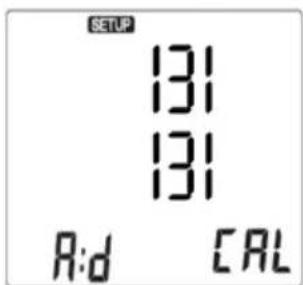
7.3 AD value calibration (only to be carried out by PCE Instruments)
- Plug the thermocouple connectors into the T1 and T3 connections so that the positive and negative poles are short circuited.
- Press both the SET and the ← key at the same time. At this time, the A:d and CAL icons (flash) on the LCD.
- Press the key to calibrate the AD value. If you need to cancel, press and hold the or key.
Warning:
This calibration must only be carried out by PCE Instruments.
8 Maintenance and cleaning
8.1 Cleaning and storage
- The white plastic sensor dome should be cleaned with a damp, soft cloth, if necessary.
- Store the temperature data logger in an area with moderate temperature and relative humidity.
8.2 Charging the battery
When the battery power is insufficient, the battery icon appears on the LCD and flashes. Use the DC 5V power adaptor to connect to the micro USB charging port at the bottom of the meter. The battery icon on the LCD indicates that the battery is charging and will disappear when the battery is fully charged.
9 Contact
If you have any questions, suggestions or technical problems, please do not hesitate to contact us. You will find the relevant contact information at the end of this user manual.
10 Disposal
For the disposal of batteries in the EU, the 2006/66/EC directive of the European Parliament applies. Due to the contained pollutants, batteries must not be disposed of as household waste. They must be given to collection points designed for that purpose.
In order to comply with the EU directive 2012/19/EU we take our devices back. We either re-use them or give them to a recycling company which disposes of the devices in line with law.
For countries outside the EU, batteries and devices should be disposed of in accordance with your local waste regulations.
If you have any questions, please contact PCE Instruments.



PCE Instruments contact information
Germany France Spain
PCE Deutschland GmbH PCE Instruments France EURL PCE Ibérica S.L.
Im Langel 26 23, rue de Strasbourg Calle Mula, 8
D-59872 Meschede 67250 Soultz-Sous-Forets 02500 Tobarra (Albacete)
Chester Rd, Old Trafford
Manchester M32 0RS
United Kingdom
Tel: +44 (0) 161 464902 0
Fax: +44 (0) 161 464902 9
info@pce-instruments.co.uk
www.pce-instruments.com/english
Italy
PCE Italia s.r.l.
Via Pesciatina 878 / B-Interno 6
55010 Loc. Gragnano Pehlivan Sok. No.6/C
Capannori (Lucca)
Italia
www.pce-instruments.com/turkish
The Netherlands
PCE Brookhuis B.V.
Institutenweg 15
7521 PH Enschede
Nederland
Telefoon: +31 (0)53 737 01 92
info@pcebenelux.nl
www.pce-instruments.com/dutch
info@pce-americas.com
www.pce-instruments.com/us
United States of America
PCE Americas Inc.
1201 Jupiter Park Drive, Suite 8
Jupiter / Palm Beach
33458 FL
USA
Tel: +1 (561) 320-9162
Fax: +1 (561) 320-9176
Denmark
PCE Instruments Denmark ApS
Birk Centerpark 40
7400 Herning
Denmark
- User Manual
- Contents
- Safety notes
- Delivery scope
- Device description
- Key description
- Note:
- Display
- Operating instructions
- Switch the meter on/off
- Set the type of thermocouple
- Connect the probe to meter
- Measurement
- MAX, MIN & AVG value
- Hold data
- Recording mode
- Data recording and software installation
- Auto Power Off
- Settings
- Enter and exit setup
- Set the type of thermocouple probe
- Set the date
- Set the time
- Setting the interval for data logging
- Setting the compensation
- Calibration
- Preparation for calibration
- Cold-junction compensation calibration
- AD value calibration (only to be carried out by PCE Instruments)
- Warning:
- Maintenance and cleaning
- Cleaning and storage
- Charging the battery
- Contact
- Disposal
- PCE Instruments contact information
- Germany France Spain
- Italy
- The Netherlands
- United States of America
- Denmark
Brand : PCE Instruments
Model : T 394
Category : Thermometer