T 318 - Thermometer PCE Instruments - Free user manual and instructions
Find the device manual for free T 318 PCE Instruments in PDF.


| Product Type | Digital RTD Thermometer |
| Model | PCE-T 318 |
| Display | 4-digit LCD with backlight |
| Measurement Range | -100°C to 300°C (-148°F to 572°F) |
| Resolution | 0.1°C / 0.1°F |
| Accuracy | ±(0.1% reading + 0.4°C) for °C; ±(0.1% reading + 0.8°F) for °F |
| Sensor Type | Platinum RTD (Pt100, Pt500, Pt1000 selectable, 4-wire) |
| Sampling Rate | 2 times per second |
| Data Hold | Yes, press HOLD button |
| MAX/MIN/AVG | Records maximum, minimum, and average of last 8 readings |
| Relative Mode | Yes, ΔREL button shows difference from stored value |
| Auto Power Off | After 30 minutes of inactivity (can be disabled) |
| Low Battery Indication | Visual indicator on display |
| Calibration | User calibration: Pt type selection, 0°C offset, factory reset |
| Water Resistance | IP67 |
| Power Supply | 3 x AAA 1.5V batteries, approx. 100 hours life (alkaline) |
| Dimensions | 150 x 66 x 31 mm |
| Weight | 175 g |
| Operating Environment | 0°C to 50°C, 0-80% RH, altitude up to 2000 m |
| Included Accessories | Pt-100 piercing probe (class A), 3 x AAA batteries, user manual |
| Maintenance | Clean with damp cloth; replace batteries; annual calibration recommended |
| Safety Precautions | Do not use in explosive atmospheres; avoid extreme temperatures; only use by qualified personnel |
Frequently Asked Questions - T 318 PCE Instruments
User questions about T 318 PCE Instruments
0 question about this device. Answer the ones you know or ask your own.
Ask a new question about this device
Download the instructions for your Thermometer in PDF format for free! Find your manual T 318 - PCE Instruments and take your electronic device back in hand. On this page are published all the documents necessary for the use of your device. T 318 by PCE Instruments.
USER MANUAL T 318 PCE Instruments
User Manual
Digital Thermometer PCE-T 318

User manuals in various languages (français, italiano, español, português, nederlands, türk, polski, русский, 中文) can be found by using our product search on: www.pce-instruments.com
Last change: 7 February 2018
v1.0
Contents
1 Safety notes.... 1
2 Introduction.... 2
3 Specifications.... 2
4 Symbol Definition and Button Location.... 3
5 Operation Instructions....4
5.1 Power-Up 4
5.2 Connection of the temperature probe 5
6 Selecting the Temperature Scale 5
7 Data-Hold Operation 5
8 Back light Operation....5
9 Relative Operation 5
10 MAX/MIN/AVG Operation 6
11 Auto Power Off....6
12 Low Battery Condition....6
13 Temperature Measurement....7
13.1 Correct Measurement Method....7
13.2 Connector Configuration 7
14 Temperature Meter Calibration Setup....8
15 Pt type selection....9
16 0 °C Calibration....10
17 Recall Default factory setting value....11
18 Maintenance....13
18.1 Replacing the Batteries ....13
18.2 Cleaning....13
19 Temperature Probe....14
19.1 Piercing type temperature probe ....14
19.2 Piercing type temperature probe Specification....14
20 Delivery contents 14
21 Contact....15
22 Disposal....15
1 Safety notes
Please read this manual carefully and completely before you use the device for the first time. The device may only be used by qualified personnel and repaired by PCE Instruments personnel. Damage or injuries caused by non-observance of the manual are excluded from our liability and not covered by our warranty.
- The device must only be used as described in this instruction manual. If used otherwise, this can cause dangerous situations for the user and damage to the meter.
- The instrument may only be used if the environmental conditions (temperature, relative humidity, ...) are within the ranges stated in the technical specifications. Do not expose the device to extreme temperatures, direct sunlight, extreme humidity or moisture.
- Do not expose the device to shocks or strong vibrations.
- The case should only be opened by qualified PCE Instruments personnel.
- Never use the instrument when your hands are wet.
- You must not make any technical changes to the device.
- The appliance should only be cleaned with a damp cloth. Use only pH-neutral cleaner, no abrasives or solvents.
- The device must only be used with accessories from PCE Instruments or equivalent.
- Before each use, inspect the case for visible damage. If any damage is visible, do not use the device.
- Do not use the instrument in explosive atmospheres.
- The measurement range as stated in the specifications must not be exceeded under any circumstances.
- Non-observance of the safety notes can cause damage to the device and injuries to the user.
We do not assume liability for printing errors or any other mistakes in this manual.
We expressly point to our general guarantee terms which can be found in our general terms of business.
If you have any questions please contact PCE Instruments. The contact details can be found at the end of this manual.
2 Introduction
This instrument is a digital thermometer for use with platinum-type temperature sensor. Temperature indication follows IEC751 temperature table for PT-type sensor.
3 Specifications
| Numerical Display | 4 digital liquid crystal display | |
| Measurement Range | -100 °C ... 300 °C; -148 °F ... 572 °F | |
| Resolution | 0.1 °C; 0.1 °F | |
| Sensor types | Platinum resistance temperature sensor for pt-100, pt-500, pt-1000 (selectable) 4 wires.ALPHA = 0.003850 | |
| Measurement current | Approx 0.53mA | |
| Maximum Voltage at Temperature couple Input | 60V DC or 24Vrms AC | |
| Environmental | Operating Temperature and Humidity:0 °C ... 50 °C (32 °F ... 122 °F); 0 ...80% RHStorage Temperature and Humidity:-10 °C ... 60 °C (14 °F ... 140 °F); 0 ...80% RHAltitude up to 2000 meters. | |
| Accuracy | -148 °F ... 572 °F | ±(0.1% reading + 0.8°F) |
| -100 °C ... 300 °C | ±(0.1% reading + 0.4°C) | |
| Temperature Coefficient | For ambient temperatures from 0°C ~ 18°C and 28°C ~ 50°C, for each °C ambient below 18°C or above 28°C add the following tolerance into the accuracy spec.0.01% of reading + 0.03°C (0.01% of reading + 0.06°F) | |
| Sample Rate | 2 times per second | |
| Water resistance | IP67 | |
| Dimension | 150 × 66 × 31mm | |
| Weight | 175g | |
| Option | Connection Cable | |
| Power requirement | Battery 1.5V X 3 size AAA | |
| Battery Life | Approx. 100hours with alkaline battery | |
Note:
The basic accuracy Specification does not include the error of the probe please refer to the probe accuracy specification for additional details.
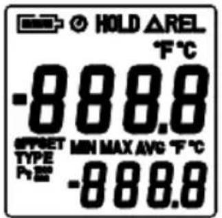
4 Symbol Definition and Button Location
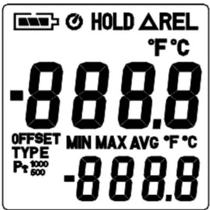
| - : This indicates that the minus temperature is sensed. |
| °C °F : Centigrade and Fahrenheit indication. |
| Pt xxx : Platinum Type Indication |
| HOLD : This indicates that the display data is being hold. |
| MAX : The Maximum value is now being displayed |
| MIN : The Minimum value is now being displayed |
| AVG : The Average value is now being displayed. |
| △REL : The reading is now under Relative Mode. |

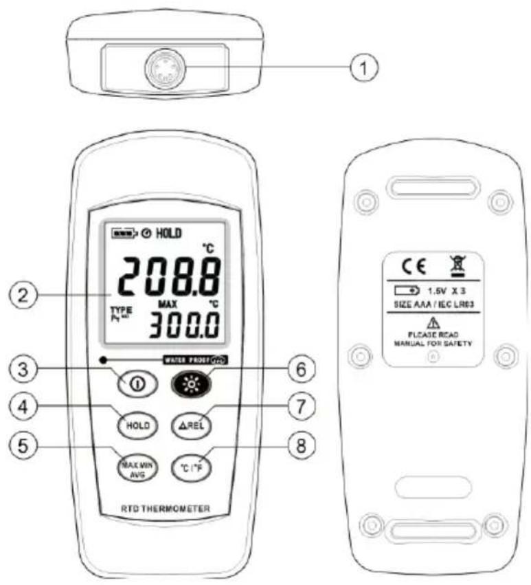
o,1 Pt type temperature sensor connector
○,2 LCD display
○,3 Power ON/OFF button
○,4 HOLD button
○,5 MAX MIN Average control button
○,6 Back light button
○,7 Relative readout button
○,8 °C , °F control button
5 Operation Instructions
5.1 Power-Up
Press the ON/OFF key to turn the thermometer ON or OFF.
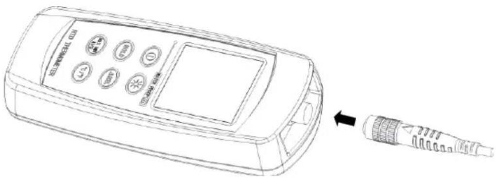
5.2 Connection of the temperature probe
For measurement, plug the temperature probe into the input connectors.
6 Selecting the Temperature Scale
When the meter was first power on, the default scale setting is set at Celsius (°C) scale. The user may change it to Fahrenheit (°F) by pressing “°C/°F” button and vice versa to Celsius.
7 Data-Hold Operation
The user may hold the present reading and keep it on the display by pressing the "HOLD" button. When the hold data is no longer needed, one may release the data-hold operation by pressing "HOLD" button again.
When the meter is under Data Hold operation, the “ΔREL”, (AVG MAX 100) and “°C/°F” button are disabled.
8 Back light Operation
Press the "Back Light" button will turn back light on and Press it once again will turn off. The meter will turn back light off if there is no push "Back Light" button for 10 seconds.
9 Relative Operation
When one press the “ΔREL” button, the meter will memorize the present reading and the difference between the new reading and the memorized data will be shown on the display. Press the “ΔREL” button again to exit the Relative operation.
10 MAX/MIN/AVG Operation
When you press the "MAX MIN" button the meter will enter the MAX/MIN/AVG mode. Under this mode the maximum value, minimum value and average value of latest 8 data is kept in the memory simultaneously and updated with every new data.
When the MAX symbol is display, the Maximum is shown on the display.
Press "MAX MIN" again, then the NIN symbol is on the display and also the minimum reading.
Press "MAX MIN" again, the AVG symbol is on the display and also the average reading.
Press “MAX MIN” again, MAX, MIN and AVG will blink together. This means that all these data is updated in the memory and the reading is the present temperature.
One may press "MAX MIN" to circulate the display mode among these options.
When the meter is under “MAX MIN” operation, “ REL” and “ ^ C/ ^ F” are disabled.
To exit the MAX/MIN mode, one may press and hold "MAX MIN" for two seconds.
11 Auto Power Off
By default, when the meter is powered on, it is under auto power off mode. The meter will power itself off after 30 minutes if no key operation.
One may press and hold "HOLD" button and then power on the meter and there will be two successive beeps to indicate that auto power off is disabled.
12 Low Battery Condition
The temperature meter incorporates visual low battery indication as follows:
 | Battery OK, measurements are possible. |
 | Battery Low, battery needs to be replaced, measurements are still possible. |
 | Battery exhausted, the battery need to replaced with new one(size AAA, 1.5V x 3). |
13 Temperature Measurement
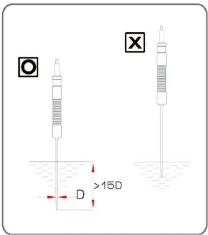
13.1 Correct Measurement Method
The temperature sensor is located at the end of the metal sheath of the sheath type TEMPERATURE PROBE. To accurately test internal temperature insert the probe into the item you want to measure to a distance at least 15 times the diameter of the sheath.
13.2 Connector Configuration
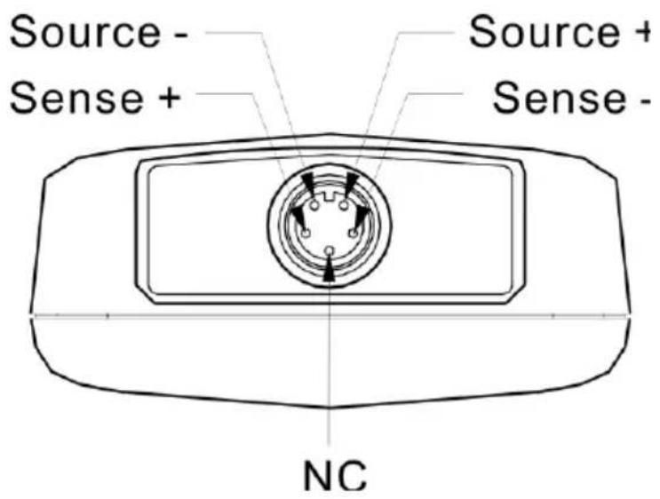
14 Temperature Meter Calibration Setup
Below table diagram shows each button function when user enter into calibration mode.
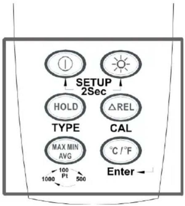
flowchart
graph TD
    A["SETUP 2Sec"] --> B["HOLD"]
    A --> C["△REL"]
    B --> D["TYPE"]
    C --> E["CAL"]
    D --> F["MAX MIN AVG"]
    E --> G["℃/°F"]
    F --> H["Enter"]
    G --> H
    H --> I["1000 Pt"]
    I --> J["1000"]
    J --> K["500"]
Note:
Turn the Power "OFF" before attempting following SETUP.
Setup mode is cancelled during below procedure if "POWER" button is pressed.
15 Pt type selection
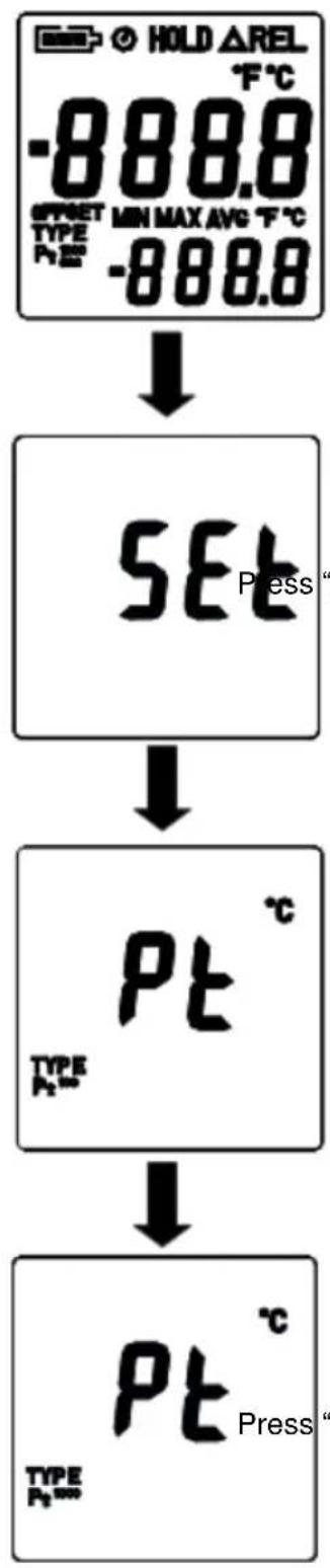
flowchart
graph TD
    A["SET Press"] --> B["Pt"]
    B --> C["Pt Press"]
Press and hold "Power" + "Light" buttons for 2 seconds to enter setup mode.
Press "Hold" button to enter Pt selection mode.
Press "Max" button to select between Pt probe type. (Pt100, Pt500, Pt1000 is circulate)
Press "°C/°F" button to confirm selection.
16 0 °C Calibration
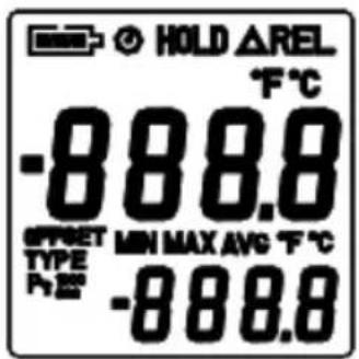
Press and hold "Power" + "Light" buttons for 2 seconds to enter setup mode.
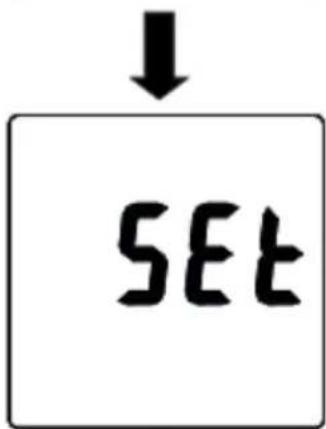
Press "REL" button to enter calibration mode. Enter Pt selection first.
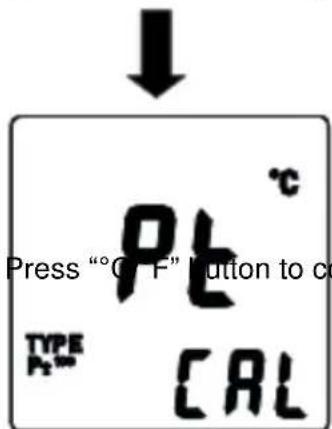
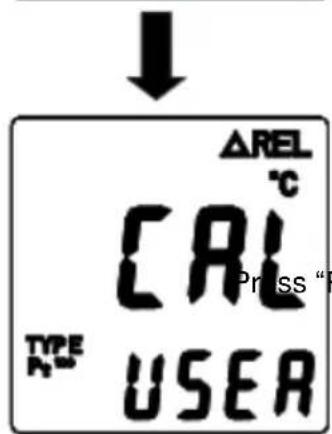
onfirm Pt selection
REL" button to enter calibration mode.
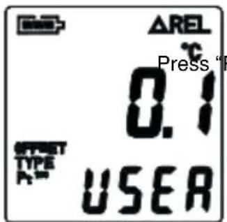

Press "REL" button to confirm present calibration value.
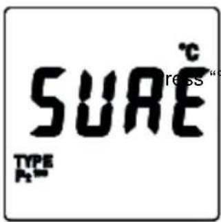
press "°C/°F" button to confirm selection.
17 Recall Default factory setting value

Press and hold "Power" + "Light" buttons for 2 seconds to enter setup mode.
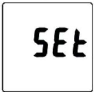
SET
Press "REL" button to enter calibration mode. Enter Pt selection first.
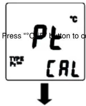
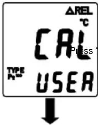
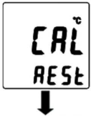
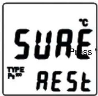
"light" button to enter recall mode.
Press “°C/°F” button to confirm revert back to “Default factory setting value”
°C/°F" button to confirm selection.
18 Maintenance
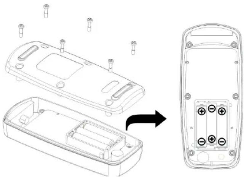
18.1 Replacing the Batteries
(1) Remove back cover screw to remove cover. Verify polarity and install new LR03(AAA size) alkaline batteries.
(2) Fit cover properly and tighten screw.
The unit's back cover is fitted with rubber rings. After replacing the battery, check that the rubber rings are properly seated before reinstalling the back cover. Improper seating of the rubber rings will compromise the unit's water-resistant structure, and possibly result in damage to the equipment.
natural_image
Technical line drawing of a device casing with internal components and mounting holes, showing assembly from top to side (no text or symbols)18.2 Cleaning
In order to ensure the accuracy of the thermometer for a longer period of time you should calibrate it once a year.
Clean the device and the window of the display with a clean, lint-free, antistatic and dry cleaning cloth.
Do no use cleaning agents that contain carbon or benzenes, alcohol or anything similar to clean the product since these substances damage the surface of the measuring instrument. Moreover, these fumes are hazardous to health and explosive. Do not use tools with sharp edges, screwdrivers, metal brushes or anything similar to clean the device.
19 Temperature Probe
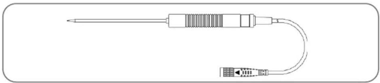
19.1 Piercing type temperature probe
natural_image
Line drawing of a soldering iron with a U-shaped terminal connector (no text or symbols)19.2 Piercing type temperature probe Specification
| Sensor Type | Platinum resistance thermometer sensor Pt 100(4 wires) |
| Accuracy | IEC751, class A ±0.15°C±0.002t (t: measurement temperature) |
| Measurement Range | -100 to 400°C |
| Temperature Sensor Dimensions | Approx. ∅3.2mm(∅0.125") |
| Temperature Sensor Length | Approx. 120 mm(4.72") |
| Cable Length | Approx. 1100 mm(43.3") |
| Water-resistant | EN60529:1991 IP67 |
20 Delivery contents
1 x digital thermometer PCE-T 310
1 x Pt-100 Probe (class A)
3 x AAA battery
1 x user manual
21 Contact
If you have any questions, suggestions or technical problems, please do not hesitate to contact us. You will find the relevant contact information at the end of this user manual.
22 Disposal
For the disposal of batteries in the EU, the 2006/66/EC directive of the European Parliament applies. Due to the contained pollutants, batteries must not be disposed of as household waste. They must be given to collection points designed for that purpose.
In order to comply with the EU directive 2012/19/EU we take our devices back. We either re-use them or give them to a recycling company which disposes of the devices in line with law.
For countries outside the EU, batteries and devices should be disposed of in accordance with your local waste regulations.
If you have any questions, please contact PCE Instruments.


PCE Instruments contact information
Germany France Spain
PCE Deutschland GmbH PCE Instruments France EURL PCE Ibérica S.L.
Im Langel 4 23, rue de Strasbourg Calle Mayor, 53
D-59872 Meschede 67250 SOULTZ-SOUS-FORETS 02500 Tobarra (Albacete)
United States of America
PCE Americas Inc.
711 Commerce Way suite 8
Jupiter / Palm Beach
33458 FL
USA
Tel: +1 (561) 320-9162
Fax: +1 (561) 320-9176
info@pce-americas.com
www.pce-instruments.com/us
United Kingdom
PCE Instruments UK Ltd
Units 12/13 Southpoint Business Park
Ensign Way, Southampton
Hampshire
United Kingdom, SO31 4RF
Tel: +44 (0) 2380 98703 0
Fax: +44 (0) 2380 98703 9
info@industrial-needs.com
www.pce-instruments.com/english
Italy
PCE Italia s.r.l.
Via Pesciatina 878 / B-Interno 6
55010 LOC. GRAGNANO
CAPANNORI (LUCCA)
Italia
www.pce-instruments.com/dutch www.pce-instruments.com/chile
Chile Hong Kong
PCE Instruments Chile S.A.
RUT: 76.154.057-2
Santos Dumont 738, local 4
Comuna de Recoleta, Santiago, Chile
Tel.: +56 2 24053238
Fax: +56 2 2873 3777
info@pce-instruments.cl
PCE Instruments HK Ltd.
Unit J, 21/F., COS Centre
56 Tsun Yip Street
Kwun Tong
Kowloon, Hong Kong
Tel: +852-301-84912
jyi@pce-instruments.com
www.pce-instruments.cn
China
PCE (Beijing) Technology Co., Ltd
1519 Room, 6 Building
Men Tou Gou Xin Cheng,
Men Tou Gou District
102300 Beijing
China Tel: 0212 471 11 47
Tel: +86 (10) 8893 9660
info@pce-instruments.cn info@pce-cihazlari.com.tr
www.pce-instruments.cn
Turkey
Pehlivan Sok. No.6/C
www.pce-instruments.com/turkish
- User Manual
- Contents
- Safety notes
- Introduction
- Specifications
- Note:
- Symbol Definition and Button Location
- Operation Instructions
- Power-Up
- Connection of the temperature probe
- Selecting the Temperature Scale
- Data-Hold Operation
- Back light Operation
- Relative Operation
- MAX/MIN/AVG Operation
- Auto Power Off
- Low Battery Condition
- Temperature Measurement
- Correct Measurement Method
- Connector Configuration
- Temperature Meter Calibration Setup
- Pt type selection
- 0 °C Calibration
- Recall Default factory setting value
- Maintenance
- Replacing the Batteries
- Cleaning
- Temperature Probe
- Piercing type temperature probe
- Piercing type temperature probe Specification
- Delivery contents
- Contact
- Disposal
- PCE Instruments contact information
- Germany France Spain
- United States of America
- United Kingdom
- Italy
- Chile Hong Kong
- China
- Turkey
Brand : PCE Instruments
Model : T 318
Category : Thermometer