
9070 - Drill Hazet - Free user manual and instructions
Find the device manual for free 9070 Hazet in PDF.


| Product Type | Compressed Air Maintenance Unit / Filter-Pressure Reducer |
| Model Numbers | 9070-2, 9070-3, 9070-4, 9070-5, 9070-6, 9070-7 |
| Connecting Thread | 1/2" (9070-2, 9070-5), 3/8" (9070-3, 9070-6), 1/4" (9070-4, 9070-7) |
| Flow Rate at 6.3 bar | 5000 Nl/min (1/2" and 3/8" models), 1800 Nl/min (1/4" models) |
| Working Pressure (max) | 12 bar (1/2" and 3/8" models), 10 bar (1/4" models) |
| Maximum Pressure | 16 bar (1/2" and 3/8" models), 12 bar (1/4" models) |
| Pressure Indication Range | 0.5–12 bar (1/2" and 3/8"), 0.5–10 bar (1/4") |
| Permissible Temperature Range | -10 °C to +55 °C |
| Filter Cup Capacity | 50 ml (1/2" and 3/8"), 30 ml (1/4") |
| Oil Cup Capacity | 170 ml (9070-2/-3/-4), None (9070-5/-6/-7) |
| Oil Filter Element Size | 10 μm |
| Manometer Connection | 1/8" |
| Condensate Drain Type | Semi-automatic and manual |
| Oil Flow Regulation | Adjustable via regulator knob |
| Included Components (9070-2/-3/-4) | Maintenance Unit (Filter-Pressure Reducer + Lubricator) |
| Included Components (9070-5/-6/-7) | Filter-Pressure Reducer only |
| Appropriate Use | Filtering, pressure reducing, and lubricating compressed air |
| Cleaning Method | Soap and water only; avoid solvents and brake oils |
| Spare Parts Requirement | Use only manufacturer's original spare parts |
| Storage Temperature | -10 °C to +55 °C |
| Relative Humidity (max) | 65% |
| Compatible Oil Examples | HAZET pneumatic special oil 9400-100, ISO/UNI FD oils |
| Manometer Outlets | Front and rear; unused outlet to be closed with threaded plug |
| Weight (approx) | Not specified in manual; estimate ~1.5 kg |
Frequently Asked Questions - 9070 Hazet
User questions about 9070 Hazet
0 question about this device. Answer the ones you know or ask your own.
Ask a new question about this device
Download the instructions for your Drill in PDF format for free! Find your manual 9070 - Hazet and take your electronic device back in hand. On this page are published all the documents necessary for the use of your device. 9070 by Hazet.
USER MANUAL 9070 Hazet


Operating instructions Maintenance Unit for Compressed Air/ Filter-Pressure Reducer

9070
1. For Your Safety

Before working with the tool, please read thoroughly this application note as well as the instructions for pneumatic tools.
For effective use of the tool set as intended, it is essential that all safety and other information in this application note is adhered to.
HAZET will not be liable for any injuries to persons or damage to property originating from improper application, misuse of the tool or a disregard of the safety instructions. These injuries are the sole responsibility of the owner.
2. Explanation of Symbols
ATTENTION: Please pay attention to these symbols! READ THE OPERATING INSTRUCTIONS AND APPLICATION NOTES!

ner of this tool set is obliged to observe the application note and safety instructions and should ensure that all users of this tool set use it according to the information given.
NOTICE!

abol marks advice which is helpful when using the tool set.
CAUTION!

bol marks important specifications, dangerous conditions, safety risks and safety advice.
ATTENTION!
This symbol marks advice which if disregarded results in damage, malfunction and/or functional failure of the tool set.
3. Spare Parts
- For safety reasons, only the manufacturer's original spare parts may be used.
- Unsuitable or defective spare parts may cause damage, malfunction or total failure of the tool.
- The use of non approved spare parts will void all warranty, service and liability claims as well as all claims for compensation against the manufacturer or its agents, distributors and sales representatives.
4. Disposal
- For disposal, clean tool and disassemble it according to the regulations for work safety and environmental protection.
- Components can be recycled.
5. Appropriate Use
- Filtering compressed air with means of an oil filter element in order to eliminate dirt and rust out of compressed-air system
- Reducing the pressure of the inlet air in order to adjust pressure to the tools in use
- Lubrication of the inlet air to prevent corrosion. (Maintenance unit only)
6. Included in delivery
9070-2, -3, -4•MaintenanceUnit Filter-Pressure Reducer Lubricator
9070-5, -6, -7 • Filter-Pressure Reducer
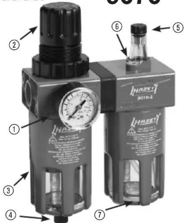
7. Tool Elements
① Manometer
② Pressure regulator
③ Filter regulator
④ Condensate drain valve
⑤ Oil flow regulator
⑥ Oil filler plug
⑦ Oil-cup
⑧ Threaded plug (at the back of the manometer)
8. Technical data
| Maintenance Unit Filter-Pressure Reducer | ||||||
| 9070-2 | 9070-3 | 9070-4 | 9070-5 | 9070-6 | 9070-7 | |
| Connecting thread | 1/2" | 3/8" | 1/4" | 1/2" | 3/8" | 1/4" |
| Flow rate at 6.3 barNI/min | 5000 | 5000 | 1800 | 5000 | 5000 | 1800 |
| Working pressure max. bar | 12 | 12 | 10 | 12 | 12 | 10 |
| Pressure max. bar | 16 | 16 | 12 | 16 | 16 | 12 |
| Pressure indication bar | 0,5–12 | 0,5–12 | 0,5–10 | 0,5–12 | 0,5–12 | 0,5–10 |
| Permissible temperatur range °C | -10 up to +55 | -10 up to +55 | -10 up to +55 | -10 up to +55 | -10 up to +55 | -10 up to +55 |
| Filter-Pressure Reducer Capacity ml | 50 | 50 | 30 | 50 | 50 | 30 |
| Oil-cupCapacity ml | 170 | 170 | 40 | - | - | - |
| Oil filter element mm | 10 | 10 | 10 | 10 | 10 | 10 |
| Manometer connection | 1/8" | 1/8" | 1/8" | 1/8" | 1/8" | 1/8" |
9. Before starting the operation

Prior to installation, please observe the air flow direction marked by arrows
- The filter-pressure reducer is equipped with a front and a rear outlet for the manometer. Close the outlet not being used with the threaded plug ⑧
- Before pressurizing the system, fill the lubricator with oil either directly by unscrewing the oil-cup ⑦ or through the oil filler plug ⑥ positioned on top of the lubricator body.

Always use suitable oils, such as HAZET pneumatic special oil 9400-100 or ISO and UNI FD oils.
10. Application
• Air pressure adjusting:
By operating the pressure regulator ② on top of the filter-pressure reducer
- Raise the pressure regulator knob ② upwards in order to permit rotation
- Increase pressure: turn the knob clockwise decrease pressure: turn the knob counterclockwise
- Once the desired pressure has been obtained, push the knob downwards in order to lock it in place.
- With a final clockwise rotation the desired pressure is built-up.
- Condensate drain
There is a condensate drain valve ④ in the lower part of the filter cup.

- Position ① – semi-automatic condensate drain: The valve knob is in central free position – valve closes if system is under pressure, condensate is drained only during the absence of pressure
- Position ② – manual condensate drain: Push the valve knob up to drain condensate manually even under pressure.
- Position ③ – manual valve closing: Turn the valve knob counterclockwise to close valve manually. Please take care to drain the condensate regularly
- Oil flow regulation
Use the oil flow regulator ⑤ on top of the lubricator in order to dose the oil quantity to be sprayed:
- turn the regulator knob clockwise to decrease the oil quantity
- turn the regulator knob counterclockwise to increase the oil quantity.
CAUTION:

The maximum inlet pressure must not exceed the values listed in the technical data.
- Do not expose the tool set to heat sources higher than 60°C.
- Avoid installing the maintenance unit and the filter-pressure reducer in places subject to shock, vibration, or other types of stress.
- Avoid installing the maintenance unit and the filter-pressure reducer in places with strong concentrations of alcohol or solvents.
- Take care not to unscrew the cups or other parts of the maintenance unit or the filter-pressure reducer without first depressurizing the system.
- Keep tool set out of reach of children.
- Incorrect use may damage the product. It is therefore essential to scrupulously observe the contents of this application note.
11. Storage

The tool set has to be stored according the following conditions:
- Do not store the tool set outdoors.
- Keep tool in a dry and dust-free place.
- Do not expose the tool to liquids and aggressive substances.
• Storage temperature: -10 up to +55 °C.
• Relative air humidity: max. 65 %.
12. Maintenance and Cleaning
- Use only soap and water to clean the cups. Do not use detergent oils, brake circuit oils, or solvents.
- Regularly drain the condensate that forms in the filter cup.

CAUTION: you are advised to use models 9070-3, 9070-4, 9070-6 and 9070-7 with GAV Sprinter ADPV 22L oil.
The use of other oils can permanently damage the product if they do not comply with the required characteristics for lubricators.




- OPERATING INSTRUCTIONS MAINTENANCE UNIT FOR COMPRESSED AIR/ FILTER-PRESSURE REDUCER
- FOR YOUR SAFETY
- EXPLANATION OF SYMBOLS
- NOTICE
- CAUTION
- ATTENTION
- SPARE PARTS
- DISPOSAL
- APPROPRIATE USE
- INCLUDED IN DELIVERY
- TOOL ELEMENTS
- TECHNICAL DATA
- BEFORE STARTING THE OPERATION
- APPLICATION
- OIL FLOW REGULATION
- STORAGE
- MAINTENANCE AND CLEANING
Brand : Hazet
Model : 9070
Category : Drill