AT-CAP-FC110 - Video Conferencing System Atlona - Free user manual and instructions
Find the device manual for free AT-CAP-FC110 Atlona in PDF.


| Product Type | Video Conferencing ePTZ Camera |
| Brand | Atlona |
| Model | AT-CAP-FC110 |
| Sensor | 1/2.8" CMOS, 8.42 MP |
| Video Resolution (Max) | 4K@30Hz (3840x2160), MJPEG/H.264/H.265 |
| Field of View | 110° horizontal, 120° diagonal |
| Digital Zoom | 4x (fixed 1x at 4K) |
| Audio | Built-in dual microphone array, 5m (16ft) pickup range |
| Interface | USB-C 3.0 (video, audio, power) |
| Auto-Framing | Up to 6 participants |
| Control | IR remote included, On-Screen Display (OSD) menu |
| Presets | 3 programmable |
| Dimensions (H x W x D) | 210 x 74 x 48 mm (8.27 x 2.91 x 1.89 in) |
| Weight | 300 g (10.58 oz) |
| Power Consumption | <2.5W |
| Power Supply | 5V DC, 0.5A via USB |
| Operating Temperature | 0°C to 40°C (32°F to 104°F) |
| Mounting | Adjustable display clip, 1/4-20 UNC tripod thread |
| Maintenance | Clean with dry cloth only; no user-serviceable parts |
| Safety | Do not expose to rain or moisture; unplug during lightning storms |
| Certifications | CE, FCC, NDAA compliant |
| Warranty | 3-year limited |
| Compatibility | Windows, Mac; Zoom, Teams, Webex, Google Meet, etc. |
| Package Contents | Camera, IR remote, USB-C to A cable 1.8m, AAA batteries, installation guide |
Frequently Asked Questions - AT-CAP-FC110 Atlona
User questions about AT-CAP-FC110 Atlona
0 question about this device. Answer the ones you know or ask your own.
Ask a new question about this device
Download the instructions for your Video Conferencing System in PDF format for free! Find your manual AT-CAP-FC110 - Atlona and take your electronic device back in hand. On this page are published all the documents necessary for the use of your device. AT-CAP-FC110 by Atlona.
USER MANUAL AT-CAP-FC110 Atlona
natural_image
Front view of a black ATLONA-branded video camera with sensor and antenna (no visible text or symbols on body)AT-CAP-FC110
Atlona Manuals
ePTZ Camera
Version Information
Version Release Date Notes
2 Aug 2022 Clarified LED indicator descriptions on page 11.
Sales, Marketing, and Customer Support
Main Office
Atlona Incorporated
70 Daggett Drive
San Jose, CA 95134
United States
Office: +1.408.962.0515 (US/International)
Sales and Customer Service Hours
Monday - Friday: 6:00 a.m. - 4:30 p.m. (PST)
http://www.atlona.com/
International Headquarters
Atlona International AG
Tödistrasse 18
8002 Zürich
Switzerland
Office: +41 43 508 4321
Sales and Customer Service Hours
Monday - Friday: 09:00 - 17:00 (UTC +1)
Operating Notes

IMPORTANT: Visit https://www.ationa.com/product/AT-CAP-FC110 for the latest firmware updates and User Manual.
Warranty
To view the product warranty, use the following link or QR code:
https://atlona.com/warranty/.
Important Safety Information
CAUTION
RISK OF ELECTRIC SHOCK
DO NOT OPEN
CAUTION: TO REDUCT THE RISK OF
ELECTRIC SHOCK
DO NOT OPEN ENCLOSURE OR EXPOSE
TO RAIN OR MOISTURE.
NO USER-SERVICEABLE PARTS
INSIDE REFER SERVICING TO
QUALIFIED SERVICE PERSONNEL.

The exclamation point within an equilateral triangle is intended to alert the user to the presence of important operating and maintenance instructions in the literature accompanying the product.

The information bubble is intended to alert the user to helpful or optional operational instructions in the literature accompanying the product.
- Read these instructions.
- Keep these instructions.
- Heed all warnings.
- Follow all instructions.
- Do not use this product near water.
- Clean only with a dry cloth.
- Do not block any ventilation openings. Install in accordance with the manufacturer's instructions.
-
Do not install or place this product near any heat sources such as radiators, heat registers, stoves, or other apparatus (including amplifiers) that produce heat.
-
Do not defeat the safety purpose of a polarized or grounding-type plug. A polarized plug has two blades with one wider than the other. A grounding type plug has two blades and a third grounding prong. The wide blade or the third prong are provided for your safety. If the provided plug does not fit into your outlet, consult an electrician for replacement of the obsolete outlet.
- Protect the power cord from being walked on or pinched particularly at plugs, convenience receptacles, and the point where they exit from the product.
- Only use attachments/accessories specified by Atlona.
- To reduce the risk of electric shock and/or damage to this product, never handle or touch this unit or power cord if your hands are wet or damp. Do not expose this product to rain or moisture.
- Unplug this product during lightning storms or when unused for long periods of time.
- Refer all servicing to qualified service personnel. Servicing is required when the product has been damaged in any way, such as power-supply cord or plug is damaged, liquid has been spilled or objects have fallen into the product, the product has been exposed to rain or moisture, does not operate normally, or has been dropped.


FCC Compliance
FCC Compliance and Advisory Statement: This hardware device complies with Part 15 of the FCC rules. Operation is subject to the following two conditions: 1) this device may not cause harmful interference, and 2) this device must accept any interference received including interference that may cause undesired operation. This equipment has been tested and found to comply with the limits for a Class A digital device, pursuant to Part 15 of the FCC Rules. These limits are designed to provide reasonable protection against harmful interference in a commercial installation. This equipment generates, uses, and can radiate radio frequency energy and, if not installed or used in accordance with the instructions, may cause harmful interference to radio communications. However there is no guarantee that interference will not occur in a particular installation. If this equipment does cause harmful interference to radio or television reception, which can be determined by turning the equipment off and on, the user is encouraged to try to correct the interference by one or more of the following measures: 1) reorient or relocate the receiving antenna; 2) increase the separation between the equipment and the receiver; 3) connect the equipment to an outlet on a circuit different from that to which the receiver is connected; 4) consult the dealer or an experienced radio/TV technician for help. Any changes or modifications not expressly approved by the party responsible for compliance could void the user's authority to operate the equipment. Where shielded interface cables have been provided with the product or specified additional components or accessories elsewhere defined to be used with the installation of the product, they must be used in order to ensure compliance with FCC regulations.
Copyright, Trademark, and Registration
© 2022 Atlona Inc. All rights reserved. "Atlona" and the Atlona logo are registered trademarks of Atlona Inc. Pricing, specifications and availability subject to change without notice. Actual products, product images, and online product images may vary from images shown here.
All other trademark(s), copyright(s), and registered technologies mentioned in this document are the properties of their respective owner(s).
Table of Contents
Introduction 6
Features 6
Package Contents 6
Panel Description 7
Front Panel 7
Side and Bottom Panel 7
IR Remote Control 8
Installation
Connection Instructions 9
Connection Diagram 10
Device Operation 11
LED Indicator 11
Main Menu 12
Displaying the Main Menu System 12
Selecting a Submenu 12
Hiding the Menu System 13
Submenus 13
IMAGE Submenu 13
COLORTONE Submenu 15
SYSTEM Submenu 17
DEVICEINFO Submenu 19
DEFAULTS Submenu 20
IR Operation 21
Setting the IR Channel 21
Specifications 22
Introduction
The Atlona Captivate™ AT-CAP-FC110 is an enterprise-grade ePTZ camera ideal for use in video conferencing, distance learning, and other applications in huddle rooms and small to medium-sized meeting spaces. This camera features a USB-C interface for video and audio. The CAP-FC110 can be used with the Omega™ Series, AT-USB-EX100-KIT, and OmniStream™, or interfaced directly with a PC. This camera offers a 110° wide horizontal field of view and features electronic pan, tilt, and zoom capabilities, as well as an auto-framing functionality that reframes the camera based on detection of up to six participants. The CAP-FC110 delivers high-quality imaging with video resolutions up to 4K@ 30 Hz, and features a 2-microphone array with a 5 meter (16 foot) audio pickup range. It can be installed on a flat-panel display with an adjustable mounting clip, and features a 1/4-20 UNC standard screw thread for a tripod or other camera mount.
Features
- Designed for video conferencing and other applications with AV systems supporting USB interfacing and extension.
- USB-C interface for video and audio, as well as device powering.
- Universal PC and Mac® compatibility through standard UVC 1.1 (USB Video Class) enables simply plug-and-play operation.
- Works with popular soft codec and UC clients such as Microsoft Teams, Zoom, BlueJeans, Webex®, Google Meet™, GoToMeeting®, and Amazon Chime®.
- USB camera control available from compatible apps such as Zoom Rooms.
• Automatically detects and re-frames camera for up to 6 participants. - 4x digital zoom and 110^ wide horizontal field of view (zoom is fixed to 1x for 4K video).
- Fast, responsive ePTZ (electronic pan, tilt, and zoom) camera functions.
• 2-microphone array with 5 meter (16 foot) audio pickup range. - High performance imaging, fine detail, and color rendering with 1/2.8" 4K CMOS sensor.
• Available video resolutions from 640x360 up to 4K @ 30 Hz (up to 1080p with ePTZ or auto-framing). - Fast and accurate auto focus, plus auto white balance mode.
- Auto exposure mode with backlight compensation for low-lighting conditions.
• Picture controls available for brightness, color, saturation, contrast, and sharpness. - IR control – convenient handheld IR remote control included.
- Three camera presets available, accessible from IR remote.
- On-screen display (OSD) for setting up and adjusting camera settings.
- Adjustable mounting clip for installing camera on a display.
- Compatible with 1/4-20 UNC tripod screw thread standard.
• Supports wall installation below a display with third-party mounting hardware (image flip / mirroring available). - Includes installation guide, IR remote control, and 1.8 meter (6 foot) USB-C to Type-A male cable.
Package Contents
1 x AT-CAP-FC110
1 x IR remote control
1 x 1.8 meter (6 foot) USB-A to USB-C cable
2 x AAA-type 1.5 V batteries
1 x Installation guide
Panel Description
Front Panel
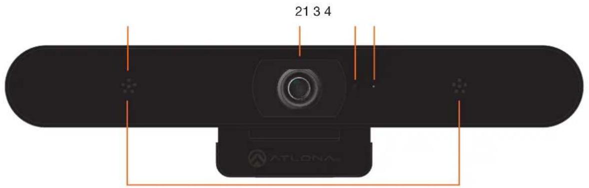
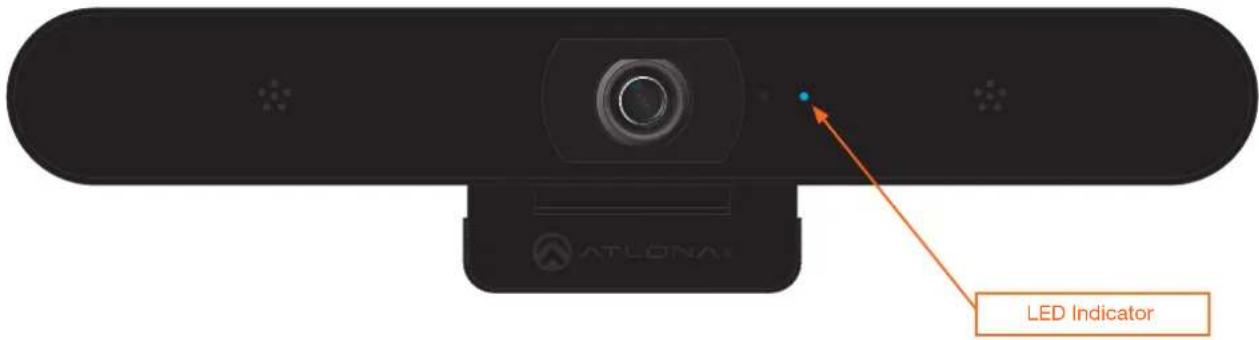
1. Microphone
Receives audio information and transmits it over the USB cable.
2. Camera Lens
Receives visual information and transmits it over the USB cable.
3. IR Sensor
Receives commands from the included IR remote.
4. LED indicator
This indicator will glow blue when the camera is in use.
Side and Bottom Panel
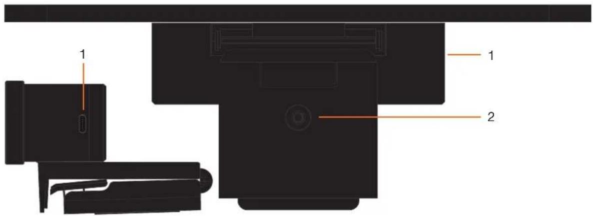
1. USB-C Port
Connect the included USB-C cable from this USB-C port to the computer.
2. 1/4"-20 UNC Thread
Attach the camera to a tripod or other camera mount using this hole.
IR Remote Control
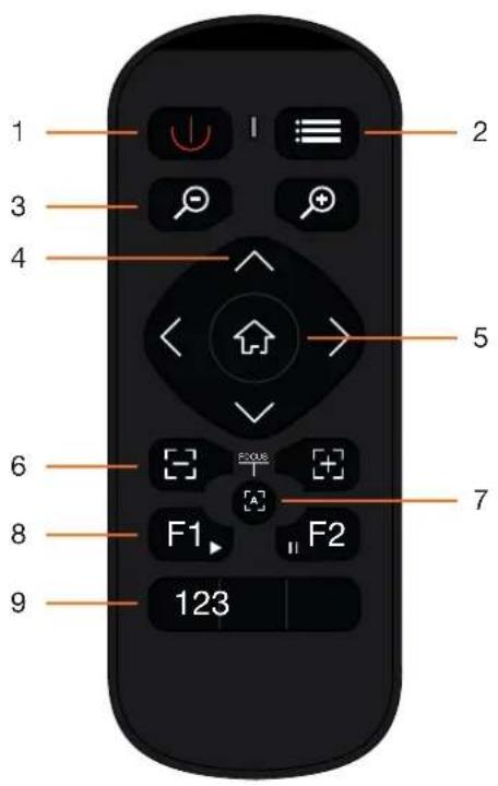
1 Power
Press this button to mute/unmute the camera and microphones.
2 Menu
Press this button to display, exit, or return to a previous sub-menu.
3 Zoom
Press these buttons to zoom in or zoom out of the current viewing area.
4 Direction
Press these buttons to position the camera view and/or select the desired option from the On-Screen Display (OSD). Press the < or > buttons to pan the camera left or right. Press the √ or ∧ buttons to adjust the tilt of the camera up or down.
5 Home
When the OSD is displayed, press this button to confirm the current selection. If the OSD is not displayed, pressing this button will return the viewing area to the default position (all zoom and panning functions are returned to normal).
6 Focus
These buttons are reserved for future use.
7 Autofocus
This button is reserved for future use.
8 Auto Framing
Press F1 to enable auto-framing. This feature will automatically frame the camera image on people in the room. Press F2 to disable auto-framing.
9 Presets
Press these buttons to set or call a preset or to change the IR channel. Refer to IR Operation (page 21) for more information on changing the IR channel.
To assign a preset to a button, press and hold the desired preset button for at least 3 seconds.
To recall a preset, press and release the desired preset button.
Installation
Connection Instructions
- Open the hinge bracket to mount the camera on top of the display.
- Connect the USB cable from the USB Port on the camera to a USB 3.0 port on the computer.
- Once the camera is initially connected to the computer, the LED indicator on the front panel will be blue for approximately 5 seconds, then turn off. When the camera stream is activated, the LED indicator will be blue until the stream is terminated.
- Remove the battery compartment cover, on the back of the included IR Remote Control, and insert the two included AAA-type batteries. Close the battery compartment.
Installation
Connection Diagram
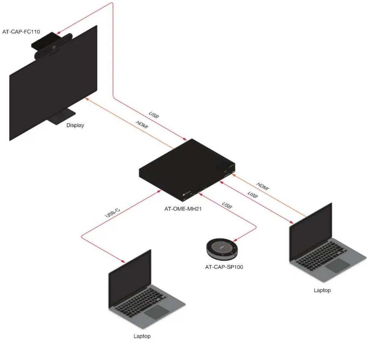
flowchart
graph TD
    A["AT-CAP-FC110"] -->|USB| B["AT-OME-MH21"]
    B -->|USB| C["Laptop"]
    B -->|USB| D["AT-CAP-SP100"]
    D -->|USB| B
    B -->|USB| E["Laptop"]
    F["Display"] --> A
Device Operation
LED Indicator
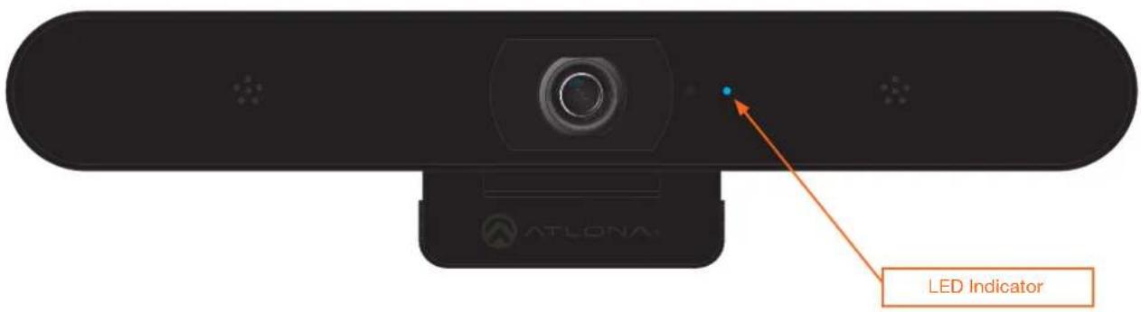
The LED indicator on the front panel of the unit provides basic information on the current status of the AT-CAP-FC110.
| LED Description | |
| Solid blue Unit is active and is streaming content. | NOTE: Once the camera is initially connected to the computer, the LED indicator on the front panel will be blue for approximately 5 seconds, then turn off. |
| Off Unit is not active and is not streaming. | Enable the camera from within the conferencing software.Check to make sure the USB cable is connected from the USB port on the AT-CAP-FC110 to the computer.Check that the USB cable, between the AT-CAP-FC110 and the computer, is secure.Try a different USB cable. |
Main Menu
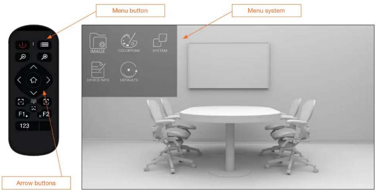
The AT-CAP-FC110 is controlled using an On-Screen Display (OSD) menu system, which is displayed using the included IR Remote Control.
Displaying the Main Menu System
-
Press and release the ☐ button on the included IR Remote Control.
-
The menu system will be displayed in the upper-left corner of the display, as shown below. Note that when any button on the IR Remote Control is pressed, the LED indicator on the front panel of the camera will flash blue and the LED indicator on the IR Remote Control will flash red.
Selecting a Submenu
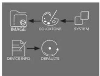
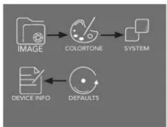
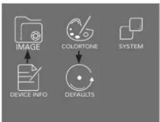
Press the < or > right arrows on the IR Remote Control to cycle though each submenu. When a submenu is selected, the text identifier for the submenu item will be enlarged and the bottom portion of the icon will contain an orange tint.
- Pressing and releasing the < button will select the menu item to the left (Figure 1), while pressing and releasing the > button will select the item to the right (Figure 2).
- Pressing and releasing the ∧ or ∨ button will select the submenu directly above or below the currently selected submenu, respectively (Figure 3).
Figure 1 Figure 2 Figure 3
flowchart
graph LR
    A["IMAGE"] --> B["COLORTONE"]
    B --> C["SYSTEM"]
    D["DEVICE INFO"] --> E["DEFAULTS"]
flowchart
graph LR
    A["IMAGE"] --> B["COLOPTONE"]
    B --> C["SYSTEM"]
    D["DEVICE INFO"] --> E["DEFAULTS"]
Hiding the Menu System
While the main submenu system is displayed, press and release the button on the included IR Remote Control. The same button is also used to return to a previous menu system.
Submenus
IMAGE Submenu
-
Press and release the button on the included IR Remote Control.
-
Select the submenu and press the button.
-
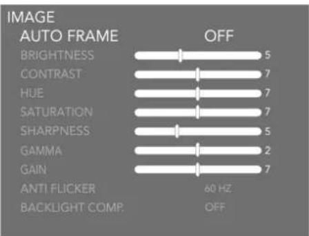
Options for the IMAGE submenu will be displayed. Pressing and releasing the ∧ or ∨ button will select the option directly above or below the currently selected option, respectively.
-
When an option is selected, press the
buttons to decrease or increase the value, respectively. If the option has an ON or OFF value, the same buttons can be used to switch between each value. -
Press and release the ☐ button to return to the Main Menu at any time.
AUTO FRAME
The AUTO FRAME feature is used to keep the primary subject in focus and centered. This feature also provides proper focus and coverage when multiple subjects are in the image, and will automatically increase the camera's Field of View (FOV) when this occurs. The available values are: ON or OFF. This feature is enabled by default.
BRIGHTNESS
Brightness is related to how much the image appears to be emitting light. Larger vales produce a brighter image, but at the same time can reduce the image contrast and make the image appear over-exposed or "blown out". Move this slider to adjust the picture brightness between a value of 0 and 14. The default setting is 5.
CONTRAST
Contrast is the difference in luminance or color. Higher values will make the objects in an image more distinguishable. Lower values tend to make the image look faded and not as clear. Move this slider to adjust the contrast between a value of 0 and 14. The default setting is 7.
HUE
Hue is one of the attributes that define the color of an object, such as red, magenta, green, and so on. Higher values will increase the red color component, while lower values will increase the green color component. Move this slider to adjust the hue between a value of 0 and 14. The default setting is 7.
SATURATION
Saturation, also referred to as “chroma”, defines the intensity of the amount of color in the image. Larger values increase the color intensity, while smaller values will make the colors appear faded. Move this slider to adjust the saturation between a value of 0 and 14. The default setting is 7.
SHARPNESS
This option increases or decreases the sharpness (or acuteness) of the image. Larger values will produce sharper edges on each object/subject in the frame. Lower values will make objects less pronounced or defined, providing a “fuzzy” outline. Move this slider to adjust the picture sharpness between a value of 0 and 14. The default setting is 5.
GAMMA
The full definition of gamma is beyond the scope of this manual. However, gamma refers to the relationship between the video level and image brightness. Cameras function differently than the human eye: eyes are much more sensitive to changes in dark tones than they are to changes in bright tones, which allows the human eye to discern a broader range of luminance values. However, for cameras, the contrast ratio (dynamic range) is too large. Therefore, to reduce the contrast of highlights, gamma correction / values are introduced. Larger values will increase the contrast ratio, making the image appear darker. Smaller values will decrease the contrast ratio, making the image appear lighter. Move this slider to adjust the gamma between a value of 0 and 4. The default value is 2.
GAIN
Gain is the amount of amplification of the signal from the camera sensor, which applies to the whole signal, including any background noise. This setting is similar to the ISO setting on a standard camera. Larger values will increase the sensor amplification, while smaller values will decrease amplification. Move this slider to adjust the contrast between a value of 0 and 14. The default setting is 7.
ANTI FLICKER
This option can be changed if displays (or lights) in the background are exhibiting a “flickering” effect. Flickering is caused when the frame rate does not match the frequency of displays and light bulbs in the environment. The default setting is 60 Hz, which is the common operating frequency for both incandescent and fluorescent bulbs in the US and Canada. UK and Australia typically operate at 50 Hz. LED lights operate above these frequencies and will not exhibit flickering. To eliminate any flickering, set the frequency to the same operating frequency of devices in the region. Available values are 60 Hz and 50 Hz.
BACKLIGHT COMP.
Backlight Compensation (BLC) is a feature which automatically adjusts the exposure control of the camera. When enabled, BLC will attempt to increase the ambient foreground light and "darken" any background light. For example, a subject standing in front of a window in the daytime, will produce a silhouetted effect. Enabling BLC will compensate for the difference in lighting. The available values are: ON or OFF. This feature is disabled by default.
COLORTONE Submenu
-
Press and release the button on the included IR Remote Control.
-
Select the 📊 submenu and press the 🔒 button.
-
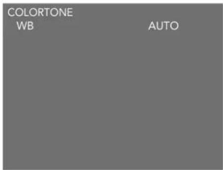
Options for the COLORTONE submenu will be displayed. The COLORTONE submenu has a single option for White Balance (WB). The available values are: AUTO, MANUAL, and STATIC.
-
When an option is selected, press the
buttons to decrease or increase the value, respectively. If the option has an ON, OFF, or other string value, the same buttons can be used to switch between each value. -
Press and release the ☐ button to return to the Main Menu at any time.
Definition: White Balance (WB) is the process of removing unnatural color casts from an image, so that objects which are physically “white” appear as “white” in the image.
WB: AUTO
When set to AUTO, this will automatically adjust the white balance based on the image. This is the default setting.
WB: MANUAL
Permits manual white balance setting using the RG (Red Gain) and BG (Blue Gain) sliders. When in MANUAL mode, select an object in the image that is physically "white". Once the object is identified, adjust the R-GAIN (Red Gain) and B-GAIN (Blue Gain) sliders so that the "white object" appears "white". When this is complete, all other objects in the scene should correctly reflect their natural colors. Move these sliders to select values from 0 through 16. The default setting for both R-GAIN and B-GAIN is 8.
Press and release the ^ or ▼ button will select between the R-GAIN and B-GAIN options.

Device Operation
WB: STATIC
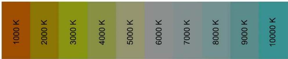
When set to STATIC mode, Color Temperature (COLOR TEMP.) is used to adjust the white balance on selected objects. When in STATIC mode, select an object in the image that is physically "white". Once the object is identified, COLOR TEMP. slider to that the "white object" appears "white". Available slider values are from 2800 to 6500 in increments of 100. The default setting is 4500K^ . Refer to Figure 4, below, for a range of general color temperatures.
Press and release the ^ or ▼ button will select between the WB and COLOR TEMP. options.
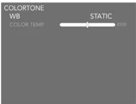
Figure 4
Color Temperature in Kelvin (K°)
heatmap
| Temperature (K) | Color Intensity | |---|---| | 1000 | Orange | | 2000 | Yellow | | 3000 | Green | | 4000 | Light Green | | 5000 | Pale Green | | 6000 | Dark Green | | 7000 | Black | | 8000 | Grey | | 9000 | Teal | | 10000 | Teal |SYSTEM Submenu
-
Press and release the button on the included IR Remote Control.
-
Select the □ submenu and press the 🏠 button.
-
Options for the SYSTEM submenu will be displayed.
| SYSTEMLANGUAGE | ENGLISH |
| IR ADDRESS | 1 |
| MIRROR | OFF |
| FLIP | OFF |
| DZOOMLIMIT | 3X |
| EXPERT MODE | OFF |
| DETECTION SENS. | HIGH |
| FRAMING MOVE SENS. | 5 |
| TARGET LOST ACT. | PRESET 1 |
| AUDIO DELAY | 0 |
-
When an option is selected, press the
buttons to decrease or increase the value, respectively. If the option has an ON, OFF, or other string value, the same buttons can be used to switch between each value. -
Press and release the button to return to the Main Menu at any time.
LANGUAGE
Sets the language of the menu system. Available options are: ENGLISH or 中文 (CHINESE).
IR ADDRESS
Sets the IR address of the camera. If multiple AT-CAP-FC110 cameras are used in an environment, they must be set to unique IR channels, to prevent interference with other IR remote control units. Once changed, the AT-CAP-FC110 will operate on that IR address. Available values are 1 through 3. Refer to IR Operation (page 21) for more information.
MIRROR
This option will mirror the image vertically, reversing the image. Available settings are ON or OFF. The default setting is OFF.
Original image (OFF) Mirrored image (ON)
FLIP
This option will flip the image horizontally, producing an upside-down image. This option is useful to correct images from cameras that are mounted upside-down or on a ceiling mount. Available settings are ON or OFF. The default setting is OFF.
Original image (OFF) Flipped image (ON)
DZOOMLIMIT
This option sets the maximum zoom limit. Available values are: 2X, 3X, and 4X. The default setting is 3X.
EXPERT MODE
When this mode is enabled, a tracking frame will be displayed on the screen. This function is typically used to analyze tracking problems in particular scenarios. Available values are: ON or OFF. The default setting is OFF.
DETECTION SENS.
This option sets the camera motion detection sensitivity. Available values are: HIGH, MIDDLE, and LOW. Note that in some cases setting this option to HIGH can result in erratic camera behavior, due to the camera attempting to track multiple subjects at once. The default setting is HIGH.
FRAMING MOVE SENS.
This setting determines how much movement is required to cause the camera to reframe. The higher the number, the smaller the movement that is required to cause a reframe. Available values are: 0 - 8. Lower values provide more precision. The default setting is 5.
TARGET LOST ACT.
Action of the camera when the smart framing target is lost. Available values are: STAY or PRESET1. When set to STAY, the camera will remain in the current position. When set to PRESET1, the camera will automatically be set to the saved preset, in PRESET1. The default setting is PRESET1.
AUDIO DELAY
In some cases, the video and audio may not be in sync. While there can be multiple causes for this behavior, depending on other equipment that is used with the camera, adjusting the this option can compensate for loss of audio sync with video. Available values are: 0, 62, 124, 186, 248, 310, 372, 434, 496, 558, 620, 682, 744, 806, 868, and 930. All values are measured in milliseconds (ms). The default value is 0.
Device Operation
DEVICEINFO Submenu
- Press and release the button on the included IR Remote Control.
- Select the DEVICE INFO submenu and press the button.
- Options for the DEVICEINFO submenu will be displayed.
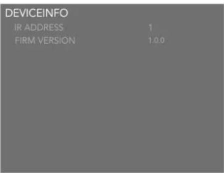
This menu has no modifiable options.
- Press and release the ☐ button to return to the Main Menu at any time.
IR ADDRESS
The IR address of the camera.
FIRM VERSION
The current firmware version of the camera.
DEFAULTS Submenu

IMPORTANT: The following procedure will reset the AT-CAP-FC110 to factory-default settings.
- Press and release the button on the included IR Remote Control.
- Select the 🧑️ submenu and press the 🔊 button.
- Options for the DEFAULTS submenu will be displayed.
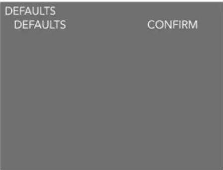
- To abort the operation, press and release the button to return to the Main Menu.
- To continue with the operation, press the button to confirm the reset-to-factory-defaults operation.
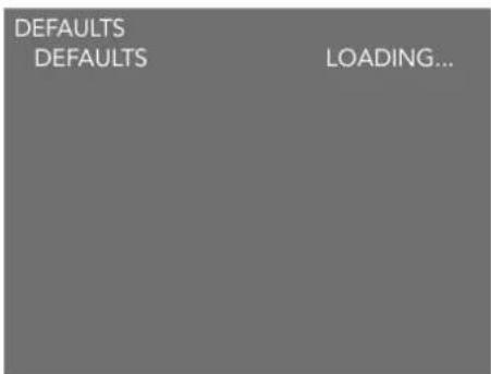
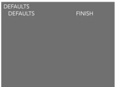
As the default settings are loaded into memory, the text on the screen will read "LOADING...", as shown below in Figure 5. Once completed, the text will change to "FINISH", as shown in Figure 6.
Figure 5 Figure 6
- Press and release the ☐ button to return to the Main Menu.
IR Operation
Setting the IR Channel
Once the desired IR channel is set on the AT-CAP-FC110, the corresponding IR channel must also be assigned to the included IR remote. The following instructions outline this procedure.
- Press and release the button on the included IR Remote Control.
- Select the □ submenu and press the ⏻ button.
- Options for the SYSTEM submenu will be displayed.
| SYSTEM | |
| LANGUAGE | ENGLISH |
| IR ADDRESS | 1 |
| MIRROR | OFF |
| FLIP | OFF |
| DZOOMLIMIT | 3X |
| EXPERT MODE | OFF |
| DETECTION SENS. | HIGH |
| FRAMING MOVE SENS. | 5 |
| TARGET LOST ACT. | PRESET 1 |
| AUDIO DELAY | 0 |
- Select the IR ADDRESS option and press the < or > button to set the IR address. In this example, the IR ADDRESS is set to 2.
| SYSTEM | |
| LANGUAGE | ENGLISH |
| IR ADDRESS | 2 |
| MIRROR | OFF |
| FLIP | OFF |
| DZOOMLIMIT | 3X |
| EXPERT MODE | OFF |
| DETECTION SENS. | HIGH |
| FRAMING MOVE SENS. | 5 |
| TARGET LOST ACT. | PRESET 1 |
| AUDIO DELAY | 0 |
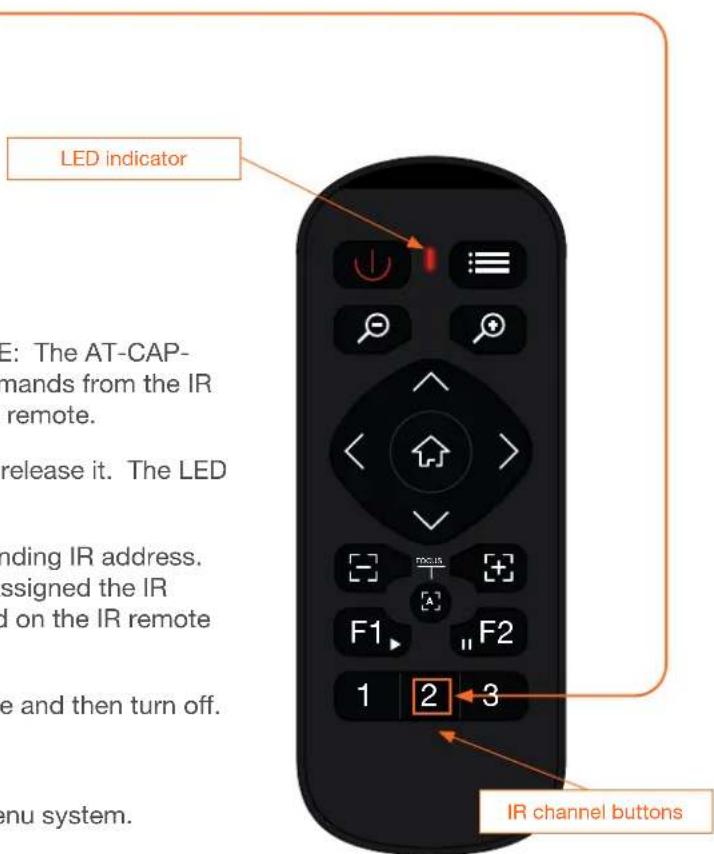
- Press the button to commit changes. NOTE: The AT-CAP-FC110 will be unable to receive any further commands from the IR remote until the IR channel is changed on the IR remote.
- Press and hold the F1 key for five seconds, then release it. The LED indicator on the IR remote will be solid red.
- Press the 1, 2, or 3 button to select the corresponding IR address. In this example, since the AT-CAP-FC110 was assigned the IR address of 2, button 2 would need to be pressed on the IR remote control.
- The LED indicator on the IR remote will blink once and then turn off.
- The IR channel has been successfully changed.
- Press and release the ☐ button to exit the menu system.
Specifications
| Video | ||
| Signal USB | ||
| Formats MJPEG, H.264, H.265 | YUY2, NV12 | |
| 3840x2160 @ 30/25 Hz,1920x1080 @ 30/25 Hz,1280x720 @ 30/25 Hz,640x360 @ 30/25 Hz | 1920x1080 @ 30/25 Hz,1280x720 @ 30/25 Hz,640x360 @ 30/25 Hz | |
| Color Space YUV, RGB | ||
| Chroma Subsampling | 4:4:4, 4:2:2, 4:2:0 | |
| Camera | |
| Sensor 1/2.8” CMOS, Progressive scan | |
| Effective Pixels 8.42 MP | |
| Focal Length f = 2.1 mm | |
| View Angle D: 120.1°, H: 109.7°, V: 87° | |
| Aperture F2.2 | |
| Digital Zoom 4X | |
| White Balance Auto, Manual, Static | |
| Video Adjustment Brightness, Contrast, Hue, Saturation, Sharpness, Gamma, Gain | |
| Exposure Control Auto | |
| SNR ≥ 50 dB | |
| Audio | |
| Audio Input | Built-in dual MIC pick-up |
| Connectors | |
| USB 1 x USB-C 3.0 | |
| Temperature Fahrenheit | Celsius | |
| Operating | +32° to 104° | 0° to +40° |
| Storage | -4° to 140° | -20° to +60° |
| Operating Humidity (RH) | 10% to 90%, non-condensing | |
| Power | ||
| Consumption | < 2.5 W | |
| Supply | 5 V DC, 0.5 A (USB) | |
| Dimensions (H x DIA) | Inches | Millimeters |
| Unit | 8.27 x 2.91 x 1.89 | 210 x 74 x 48 |
| Weight Ounces | Grams | |
| Device | 10.58 | 300 |
| Certification | |
| Device | CE, FCC |
Appendix
| Compliance | |
| NDAA-899 Yes | |
| Warranty | |
| Device 3-year limited | |


- Version Information
- Sales, Marketing, and Customer Support
- Operating Notes
- Warranty
- Important Safety Information
- CAUTION
- FCC Compliance
- Copyright, Trademark, and Registration
- Table of Contents
- Introduction
- Features
- Package Contents
- Panel Description
- Microphone
- Camera Lens
- IR Sensor
- LED indicator
- USB-C Port
- 1/4"-20 UNC Thread
- Power
- Menu
- Zoom
- Direction
- Home
- Focus
- Autofocus
- Auto Framing
- Presets
- Installation
- Connection Instructions
- Device Operation
- LED Indicator
- Main Menu
- Displaying the Main Menu System
- Selecting a Submenu
- Hiding the Menu System
- Submenus
- IMAGE Submenu
- AUTO FRAME
- BRIGHTNESS
- CONTRAST
- HUE
- SATURATION
- SHARPNESS
- GAMMA
- GAIN
- ANTI FLICKER
- BACKLIGHT COMP.
- COLORTONE Submenu
- WB: AUTO
- WB: MANUAL
- WB: STATIC
- SYSTEM Submenu
- LANGUAGE
- IR ADDRESS
- MIRROR
- FLIP
- DZOOMLIMIT
- EXPERT MODE
- DETECTION SENS.
- FRAMING MOVE SENS.
- TARGET LOST ACT.
- AUDIO DELAY
- DEVICEINFO Submenu
- FIRM VERSION
- DEFAULTS Submenu
- IR Operation
- Setting the IR Channel
- Appendix
Brand : Atlona
Model : AT-CAP-FC110
Category : Video Conferencing System