
XE3-4 - Access Point Cambium Networks - Free user manual and instructions
Find the device manual for free XE3-4 Cambium Networks in PDF.


| Product Type | Outdoor Access Point |
| Model | XE3-4 |
| Brand | Cambium Networks |
| Wireless Standard | 802.11ac Wave 2 |
| Frequency Bands | 2.4 GHz and 5 GHz |
| MIMO Configuration | 4x4 MU-MIMO |
| Maximum Data Rate | Up to 1.73 Gbps (5 GHz) + 800 Mbps (2.4 GHz) |
| Dimensions (H x W x D) | 200 mm x 200 mm x 50 mm |
| Weight | 1.0 kg |
| Power Supply | PoE (802.3af/at) |
| Power Consumption | 15 W (typical) |
| Ethernet Ports | 1x 10/100/1000 Mbps (PoE In) |
| Mounting | Wall or Pole mount (bracket included) |
| IP Rating | IP67 (outdoor rated) |
| Operating Temperature | -40°C to 55°C |
| Antenna Type | Internal directional (60° H/V beamwidth) |
| Mesh Support | Yes (Cambium cnMaestro or cloud management) |
| Security | WPA2, WPA3, AES encryption |
| Maintenance | Clean with soft dry cloth; do not use liquids or solvents |
| Spare Parts | Not user-serviceable; contact Cambium support for replacements |
| Compliance | FCC, CE, RoHS |
Frequently Asked Questions - XE3-4 Cambium Networks
User questions about XE3-4 Cambium Networks
0 question about this device. Answer the ones you know or ask your own.
Ask a new question about this device
Download the instructions for your Access Point in PDF format for free! Find your manual XE3-4 - Cambium Networks and take your electronic device back in hand. On this page are published all the documents necessary for the use of your device. XE3-4 by Cambium Networks.
USER MANUAL XE3-4 Cambium Networks
natural_image
Street view with surveillance cameras on elevated highways under a bright sky (no visible text or symbols)
Cambium Networks™

natural_image
Aerial night view of a town nestled in a valley with hills and a river in the background (no visible text or symbols)
natural_image
Young girl in blue shirt using tablet in classroom setting (no visible text or symbols)
natural_image
Overhead view of a group of people sitting around a table with laptops and tablets (no visible text or symbols)
natural_image
Desert landscape with a tall oil rig and surrounding hills under a dramatic cloudy sky (no text or symbols visible)USER GUIDE
Enterprise Wi-Fi Access Point
Release 7.1.1

natural_image
Aerial view of a coastal industrial area with storage tanks, ships, and green fields under a blue sky with clouds (no visible text or symbols)
natural_image
Man in blue shirt standing at a desk with a laptop, working in a workshop with wooden furniture and no visible text or symbols.Reservation of Rights
Cambium reserves the right to make changes to any products described herein to improve reliability, fund design, and reserves the right to revise this document and to make changes from time to time in core with no obligation to notify any person of revisions or changes. Cambium recommends reviewing the Car Networks website for the latest changes and updates to products. Cambium does not assume any liability out of the application or use of any product, software, or circuit described herein; neither does it convert under its patent rights or the rights of others. It is possible that this publication may contain references information about Cambium products (machines and programs), programming, or services that are not announced in your country. Such references or information must not be construed to mean that Cambium intends to announce such Cambium products, programming, or services in your country.
Copyrights
This document, Cambium products, ^rd Party3 software products described in this document may include or describe copyrighted Cambium and ^th Party3 supplied computer programs stored in semiconductor
memories or other media. Laws in the United States and other countries preserve for Cambium, its licer other ^rd Party supplied software certain exclusive rights for copyrighted material, including the exclusive right copy, reproduce in any form, distribute and make derivative works of the copyrighted material. Accordingly, copyrighted material of Cambium, its licensors, ^rd Party the software supplied material contained in the
Cambium products described in this document may not be copied, reproduced, reverse engineered, distribu merged or modified in any manner without the express written permission of Cambium. Furthermore, the purchase of Cambium products shall not be deemed to grant either directly or by implication, estoppel, otherwise, any license under the copyrights, patents or patent applications of Cambium or other 3rd Party supplied software, except for the normal non-exclusive, royalty free license to use that arises by operation in the sale of a product.
Restrictions
Software and documentation are copyrighted materials. Making unauthorized copies is prohibited by law. No of the software or documentation may be reproduced, transmitted, transcribed, stored in a retrieval system translated into any language or computer language, in any form or by any means, without prior written of Cambium.
License Agreements
The software described in this document is the property of Cambium and its licensors. It is furnished by license agreement only and may be used only in accordance with the terms of such an agreement.
High Risk Materials
Cambium and its supplier(s) specifically disclaim any express or implied warranty of fitness for any high-ri: activities or uses of its products including, but not limited to, the operation of nuclear facilities, aircraft navigation
or aircraft communication systems, air traffic control, life support, or weapons systems ("High Risk Use").
This product is not restricted in the EU. Any High Risk is unauthorized, is made at your own risk an responsible for any and all losses, damage or claims arising out of any High-Risk Use.
Contents
Contents .3
About This User Guide...12
Overview of Enterprise Wi-Fi AP products...12
Intended audience...12
Purpose ..12.
Feedback ..12.
Important regulatory information...13.
Complying with rules for the country of operation 13.
Related documents...14
New hardware platforms...15
Existing hardware platforms...15.
Premium feature list...16
Quick Start - Device Access...18
Powering up the device 18
PoE switches (802.3af/802.3at/802.3bt) 18
PoE switches (802.3at) 18
PoE adapter 19
DC power supply 20
Accessing the device 20
Device access using default or fallback IP 21
Device access using zeroconf IP 22
Device access using DHCP IP address 23
LED status 23
Onboarding the Device 25
Overview 25
Device onboarding and provisioning 25
cnMaestro 25
XMS-Cloud ..26
Configuring the System...27
Basic 27
Power over Ethernet (PoE)... in 29.
Power over Ethernet (PoE) Out port 32
Link Layer Discovery Protocol (LLDP)...32
Management ..34
Administrator Access...34
HTTPS Proxy server configuration...35
Time settings...36
Event logging...37.
SNMP 37
Configuring the Radio 39
Overview 39
Configuring Radio parameters 39
Basic 39
Software-Defined Radio (SDR) capabilities 48
Enhanced Roaming 52
BSS Coloring...52
Target Wake Time (TWT) 52
Receive sensitivity configuration 53
Multicast-snooping and Multicast-to-Unicast conversion 53
Boot loop detection 54
Auto-RF 55
Overview 55
Dynamic Channel 55
Dynamic Power 56
Auto-RF behavior on device turn on 56
Auto-RF Rx Sensitivity 57
Configuring Dynamic Channel 57
Configuring Dynamic Power 59
Radio Configuration 60
Configuring the Wireless LAN 62
Overview 62
Configuring the WLAN parameters 62
Basic 63
WLAN VLAN allowed list 77
ICMPv6 Router advertisement (RA) unicast conversion 77
802.11k/v 77
RADIUS server 78
Guest Access 82
Usage Limits 94
Scheduled Access 95
Access 97
Passpoint 100
RADIUS attributes 102
Enterprise PSK (ePSK) 104
Configuring ePSKs 104
ePSK registration for WPA3 clients 107
Creating a Personal Wi-Fi ePSK 116
RADIUS-based ePSK Premium feature 117
Configuring RADIUS-based ePSK 117
Groupwise Transient Key (GTK) per VLAN 119
Dynamic ARP Inspection 119
Configuring the Network 120
Overview 120
Configuring Network parameters...120.
IPv4 network parameters...120
Routes 126
IPv6 network parameters...127
General network parameters...130.
Ethernet Ports...131
DHCP 134
Tunnel 135
Point-to-Point Protocol over Ethernet (PPPoE) 138.
VLAN Pool 139
Wireless Wide Area Network (WWAN) 140
Configuring Access Control...142
Enabling Access Control Policy 142
User Group Policy...143
Device Policy 144
Managing Filters 146
Overview 146
Filter list 146
Filters 146
Configuring filter CLI 147
Device class filter 151
Wi-Fi Calling support 152
Air cleaner 152
Application control Premium feature 154
Deep Packet Inspection (DPI) 155
Custom Applications X 168
WIDS/WIPSPremium feature 171
Wireless Intrusion Detection Systems (WIDS) 171
Wireless flood detection 171
Neighbor AP detection 172
Rogue APs 172
Honeypot APs 172
Ad Hoc network detection 172
Wired Devices 173
Configuring WIDS 173
Wireless Intrusion Prevention System (WIPS) 174
Configuring Services 176
Overview 176
Configuring services 176
Lightweight Directory Access Protocol (LDAP) 176
NAT Logging 177
User Groups Premium feature 178
Real-Time Location System (RTLS) 180
Speed Test 184
DHCP Option-82 185
Bonjour Gateway 186
Link Aggregation Control Protocol (LACP) 188
Operations 190
Overview 190
Firmware upgrade 190
LED Test flashing pattern 191
Troubleshoot 192
Status 192
Downloading tech support file 193
Logging 193
Debug Logs...193
Radio Frequency (RF)...194.
Wi-Fi Analyzer...194
Packet capture...196
Performance ..198.
Network Connectivity....198
Remote CLI 200
Flash LEDs...201
XIRCON tool support...201
XIRCON tool support for Linux 1.0.0.40...202
Management Access...203
Local authentication...203
Device configuration...203
SSH Key authentication 203
Device configuration...204
SSH Key generation 204
RADIUS authentication 206
Device configuration 207
Mesh 208
Deployment scenarios 208
Mesh configurable parameters 210
Order of Mesh profile configuration 212
Mesh Auto Detect Backhaul 219
Scenario 1 219
Scenario 2 220
Scenario 3 220
Mesh Muti-Hop 224
Mesh Roaming 225
Mesh Base configuration 225
Mesh Client configuration 226
Mesh link-Sample configuration 227
VLAN 1 as the management interface 227
Non-VLAN 1 as the management interface 231
Typical use-cases 235
Additional mesh topology supported 236
Guest Access Portal - Internal 237
Introduction .237
Configurable parameters 238
Access policy 239
Splash page 239
Redirect parameters 240
Success message 241
Timeout 241
Whitelist 241
Configuration examples 241
Guest Access Portal - External 243
Introduction 243
Configurable parameters 243
Access policy 244
WISPr 244
External portal post through cnMaestro 244
External portal type 244
Redirect parameters 244
Success message 245
Timeout 245
Whitelist 245
Configuration examples...245
Guest Access - cnMaestro 247
Auto VLAN 248
Device Recovery Methods 249
Factory reset via 'RESET' button 249
Boot partition change via power...cycle...249.
Disable factory Reset Button 250
Command-Line Interface (CLI) 251
Show commands 251
Service commands...254
Service show 254
Service system...255
cnMaestro X Assurance...257
MarketApps 258
Target audience 258
Benefits 258
AFC 259
Supported AP firmware version 259
Supported cnMaestro version 259
Supported countries 259
AFC 6 GHz frequency range support 259
Prerequisites for AFC Operation 260
AFC Operation 260
AFC information in dashboard 262
GPS configuration CLIs 263
AFC Troubleshooting 263
Verify GPS information received by the AP 263
Verify AFC server connection status and information 264
AFC events...264
Glossary 265
Appendix 267
Supported RADIUS Attributes...268
WISPr VSAs (Vendor ID: 14122)....268.
Cambium VSAs (Vendor ID: 17713) ... 269
Standard RADIUS attributes...272
RADIUS attributes in authentication and accounting packets with WPA2-Enterprise security 274
Supported CoA messages...277
Supported DFS channels...278
Supported 6 GHz countries...279.
Priority order for parameters...282
Reasons for AP restarting...282
Best practices for wireless clients seamless roaming across APs 283
External network recommendations 283
AP WLAN profile configuration recommendations 284
AP group configuration recommendations 286
Cambium Networks 288
This section describes the following topics:
• Overview of Enterprise Wi-Fi AP products
- Intended audience
- Purpose
- Feedback
• Important regulatory information
- Related documents
• New hardware platforms
• Existing hardware platforms
- Premium feature list
Overview of Enterprise Wi-Fi AP products
This User Guide describes the features supported by Enterprise Wi-Fi Access Point (AP), and provides detailed instructions for setting up and configuring Enterprise Wi-Fi AP.
Intended audience
This guide is intended for use by the system designer, system installer, and system administrator.
Purpose
Cambium Network's Enterprise Wi-Fi AP documents are intended to instruct and assist personnel in operation, installation, and maintenance of Cambium's equipment and ancillary devices. It is recommended that all personnel engaged in such activities be properly trained.
Cambium disclaims all liability whatsoever, implied or expressed, for any risk of damage, loss, or re-system performance arising directly or indirectly out of the failure of the customer, or anyone acting customer's behalf, to abide by the instructions, system parameters, or recommendations made in this document.
Feedback
We appreciate feedback from the users of our documents. This includes feedback on the structure, accuracy,
or completeness of our documents. To provide feedback, visit our support website: https://support.cambiumnetworks.com.
Important regulatory information
Complying with rules for the country of operation
USA specific information

Caution
This device complies with Part 15 of the Federal Communications Commission (FCC) Rules Operation is subject to the following two conditions:
• This device may not cause harmful interference, and
- This device must accept any interference received, including interference that may cause undesired operation of the device.

Note
This equipment has been tested and found to comply with the limits for a Class B di pursuant to part 15 of the FCC Rules. These limits are designed to provide reasonable protection against harmful interference in a residential installation. This equipment generates, uses and can radiate radio frequency energy and, if not installed and used in accordance with the instructions, may cause harmful interference to radio communications. However, there is no guarantee that interference will not occur in a particular installation. If this equipment cause harmful interference to radio or television reception, which can be determined by turning the equipment off and on, the user is encouraged to try to correct the interference one or more of the following measures:
- Reorient or relocate the receiving antenna.
- Increase the separation between the equipment and receiver.
- Connect the equipment into an outlet on a circuit different from that to which the is connected.
- Consult the dealer or an experienced radio/TV technician for help.
Canada specific information

Caution
This device complies with Innovation, Science and Economic Development Canada (ISEDC) licenseexempt RSSs. Operation is subject to the following two conditions:
- This device may not cause harmful interference, and
- This device must accept any interference received, including interference that may cause undesired operation of the device.
Europe specific information
Cambium Networks Enterprise Wi-Fi AP products are compliant with applicable European Directives required for CE marking:
• 2014/53/EU of the European Parliament and of the Council of 16 April 2014 on the harmonizati laws of the Member States relating to the making available on the market of radio equipment repealing Directive 1999/5/EC; Radio Equipment Directive (RED).
• 2011/65/EU of the European Parliament and of the Council of 8 June 2011 on the restriction of certain hazardous substances in electrical and electronic equipment (RoHS Directive).
- Cambium Networks complies with the European Regulation 2023/988 of 10 May 2023 on General Product Safety. EU Authorized Representative: Cambium Networks Europe B.V., Muiderstraat 1, 1011P Amsterdam, Netherlands. Contact Information: GPSR@cambiumnetworks.com.
Related documents
Table 1 provides details of related documents for Enterprise Wi-Fi AP.
Table 1 Related documents
| Document Name Location | |
| Enterprise Wi-Fi AP product details https://www.cambiumnetworks.com/products/wifi/ | |
| Enterprise Wi-Fi AP Hardware and Installations//support.cambiumnetworks.com/filesGuide | |
| Enterprise Wi-Fi AP User Guide (This document) https://support.cambiumnetworks.com/files | |
| Enterprise Wi-Fi AP Release Notes https://support.cambiumnetworks.com/files | |
| Enterprise Wi-Fi AP Command-Line Interfachttps://support.cambiumnetworks.com/filesReference Guide | |
| Software Resources https://support.cambiumnetworks.com/files | |
| Community http://community.cambiumnetworks.com/ | |
| Support https://www.cambiumnetworks.com/support/contact-support/ | |
| Warranty https://www.cambiumnetworks.com/support/warranty/ | |
| Feedback support@cambiumnetworks.com | |
New hardware platforms
Table 2 lists the new hardware platforms introduced in Enterprise Wi-Fi Access Points.
Table 2 New hardware platforms
| Hardware Platform | Description Supported | Software Version |
| X7-53X 2x2:2, 4x4:4 802.11b/g/n/ac/ax/be Dual-Radio Indoor Wi-Fi 7 Access RePoint 7.1.1 and above | ||
| X7-55X 2x2:2, 4x4:4, 4x4:4 802.11b/g/n/ac/ax/be Tri-Radio Indoor Wi-Fi 7 Point 2+4+4: third radio SDR 5/6GHz, 5GbE, with IoT radio | Release 7.1.1 and above | |
Existing hardware platforms
Table 3 lists the existing hardware platforms in Enterprise Wi-Fi Access Points:

Warning
Release 6.x is no longer supported on Wi-Fi 5 APs. It was provided for the Wi-Fi 5 BETA release only. Any issues on these APs running release 6.x will not be supported Cambium Support team.
Table 3 Existing hardware platforms
| Hardware Platform | Description Supported Software Version | |
| XV3-8 | 8x8:8, 4x4:4 802.11a/b/g/n/ac wave 2/ax Tri-Radio Access Point | Release 6.0 and above |
| XV2-2 | 2x2:2, 2x2:2 802.11a/b/g/n/ac wave 2/ax Dual-Radio Indoor Access Point | Release 6.1 and above |
| XV2-2T0 2x2:2, 2x2:2 802.11a/b/g/n/ac wave 2/ax Dual-Radio Outdoor Access Point, Omni, PoE out | Release 6.3.5.1 and above | |
| XV2-2T1 Outdoor Wi-Fi 6 Access point, 2x2 Sector antenna band 802.11ax 2x2, BLE, 2.5GbE | Release 6.4.1 and above | |
| XV2-22H 2x2:2, 2x2:2 802.11a/b/g/n/ac wave 2/ax Dual-Radio Indoor Wi-Fi 6 Wall-Plate Access Point | Release 6.5 and above | |
| XV2-21X 2x2:2, 2x2:2 802.11a/b/g/n/ac wave 2/ax Dual-Radio Indoor Wi-Fi 6 Access Point | Release 6.5 and above | |
| XV2-23T 2x2:2, 2x2:2 802.11a/b/g/n/ac wave 2/ax Dual-Radio Outdoor Wi-Fi 6 Access Point | Release 6.5 and above | |
| XE3-4 4x4:4; 2x2:2; 2x2:2 802.11a/b/g/n/ac wave 2/ax Tri-Rad Indoor Wi-Fi 6e Access Point | Release 6.4 and above | |
| XE3-4TN 4x4:4, 2x2:2, 2x2:2 802.11b/g/n/ac wave 2/ax Tri-Rad Outdoor Wi-Fi 6e Access point | Radio Release 6.5.1 and above• Release 6.6.2 and above to support 6 GHz LPINote: Low Power Indoors (LPI) is for indoor use only | |
| XE5-8 8x8:8, 4x4:4, 4x4:4, 4x4:4 802.11a/b/g/n/ac wave 2/ax Band AP with multi-radio SDR | Release 6.4.1 and above | |
| X7-35X 2x2:2 802.11b/g/n/ac/ax/be Tri-Radio Indoor Wi-Fi 7 Access Point with IoT radio | Release 7.0 and above | |
Premium feature list
Enterprise Wi-Fi AP firmware support certain advanced features that are available only through a pai subscription to cnMaestro X. These features are identified with the label Premium feature in the
documentation. End users can also access these features without a management subscription on a basis and for a limited time. As Cambium Networks releases new versions, restrictions will be enforced the use of these premium features only in conjunction with a current cnMaestro X subscription. If does not have a current subscription at that time, the APs will stop enabling configurations, including premium features.
Table 4 Premium feature list
| Feature Name Release Details | |
| Wireless Intrusion Detection Systems (WIDS) | Release 6.4.2 |
| RADIUS-based ePSK Release 6.4 | |
| Stanley AeroScout Location Engine Release 6.3 | |
| User Groups Release 6.2 | |
| Advanced Filters (QoS, DSCP, Schedule, and Rate limit) Release 6.0 | |
| Application Control Release 6.0 |
Quick Start - Device Access
This chapter describes the following topics:
• Powering up the device
- Accessing the device
- LED status
Powering up the device
This section includes the following topics:
• PoE switches (802.3af/802.3at/802.3bt)
• PoE switches (802.3af/802.3at/802.3bt)
- PoE adapter
• DC power supply
Enterprise Wi-Fi AP product family can be powered using an Ethernet PoE Switch or a PoE midsp. Note that some APs can be powered by 802.3af, while others may require 802.3at or 802.3bt. And some APs can be powered with an external power supply. Refer to the related product datasheet determine the options available.
PoE switches (802.3af/802.3at/802.3bt)
PoE switches (802.3at)
Enterprise Wi-Fi APs negotiate the power via the LLDP mechanism. Figure 1 represents the Enterprise Wi-Fi AP Eth1 port connecting to a switch (PoE PSE Port).
Figure 1 Installation of Enterprise Wi-Fi AP to PSE port

Table 5 provides detailed information on the AP modules that are enabled based on power negotiated via LLDP.
Table 5 Power management policy
| Platform | IEEE 802.3af(12.95W @ PD) | IEEE 802.3at(25.5W @PD) | IEEE 802.3btClass - 0/1/2/3/(40W @ PD) | IEEE 802.3bClass - 5/6 (5@ PD) | IEEE 802.3b ClassW 7/8 (64W @ PD) |
| XV3-8 | √ √ | √ | |||
| XV2-2 | √ | √ | |||
| XV2-2T0 | √ √ | √ √ | |||
| XV2-2T1 | √ √ | √ √ | |||
| XV2-22H | √ | √ | |||
| XV2-21X | √ | √ | |||
| XV2-23T | √ | √ | |||
| XE3-4 | √ √ | √ | |||
| XE3-4TN | √ √ | √ √ √ | |||
| XE5-8 | √ √ | √ √ | |||
| X7-35X | √ |
PoE adapter
To power up the device using a PoE adapter, perform the following steps:
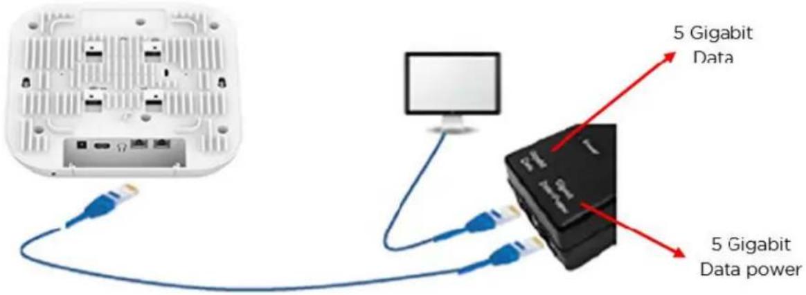
- Connect the Ethernet cable from the Eth1/PoE-IN port of the device to the 5 Gigabit Data + the PoE adapter.
- Connect an Ethernet cable from your LAN or computer to the 5 Gigabit Data port of the Po
Figure 2 Installation of Enterprise Wi-Fi AP to a PoE adapter
- Connect the power cord to the adapter, and then plug the power cord into a power outlet Figure 3. Once powered ON, the Power LED should illuminate continuously on the PoE adapter.
Figure 3 Connecting PoE adapter to a power outlet

DC power supply
The Enterprise Wi-Fi AP XV3-8 has an option to power via a DC power adapter through the bar. If the device is connected to both the DC power adapter and the PoE adapter, then the DC po takes precedence.
Accessing the device
This section includes the following topics:
• Device access using default or fallback IP
• Device access using zeroconf IP
• Device access using DHCP IP address
Once the device is powered up, ensure it is operational by checking the LED status. The power AP should turn green, which indicates that the device is ready for access.
Device access using default or fallback IP
To configure the computer to access the device using the default or fallback IP, perform the follo
-
Open Local Area Connection Properties by performing one of the following steps:
-
In computers running Windows 7 operating system, go to Control Panel > Network and Internet > Network Connections > Local Area Connection > Properties (in the Local Area Connection Status window).
- In computers running Windows 10 operating system, go to Control Panel > Network and Internet > Network and Sharing Center > Local Area Connection > Properties (in the Local Area Connection Status window).
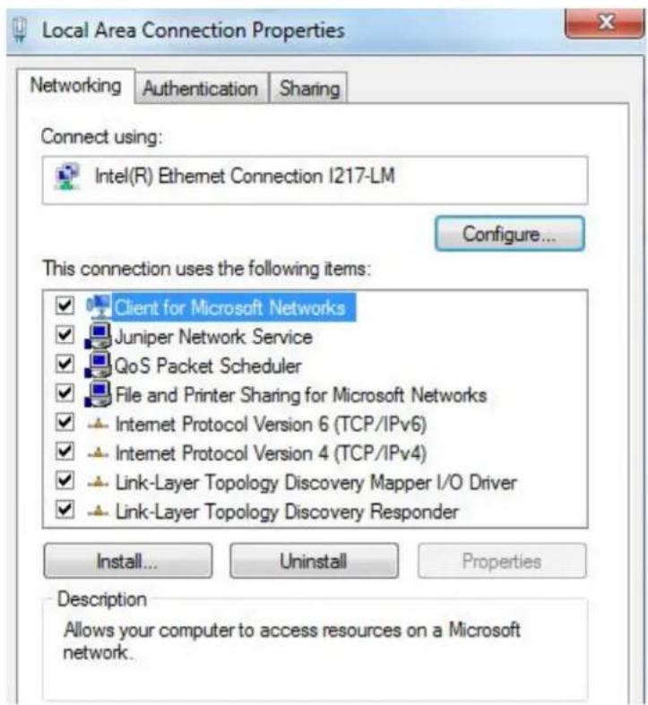
The AP obtains its IP address from a DHCP server. A default IP address of 192.168.0.1/24 is address is not obtained from the DHCP server.
- Select Internet Protocol Version 4 (TCP/IPv4) and click Properties.
The Internet Protocol Version 4 (TCP/IPv4) Properties dialog box appears, as shown below:

- In the Use the following IP address section, ensure that an appropriate IP address and a subnet address are provided.
- Click OK.
- Ensure that your computer is set up to communicate with the required range of IP addresses.
- Open a web browser and type the URL - http://192.168.0.1 - to access the device UI. The Si appears.
-
Type an appropriate username and password.
-
Default username: admin
-
Default password: admin
-
Click Sign In.
Device access using zeroconf IP
To configure the computer to access the device using the zeroconf IP, complete the following step
-
Convert the last two bytes of ESN of the device to decimal. If ESN is 58:C1:CC:DD:AA:BB, last of this ESN is AA:BB. Decimal equivalent of AA:BB is 170:187. Zeroconf IP of the device with 58:C1:CC:DD:AA:BB is 169.254.170.187.
-
Configure Management PC with 169.254.100.100/16, as described below:
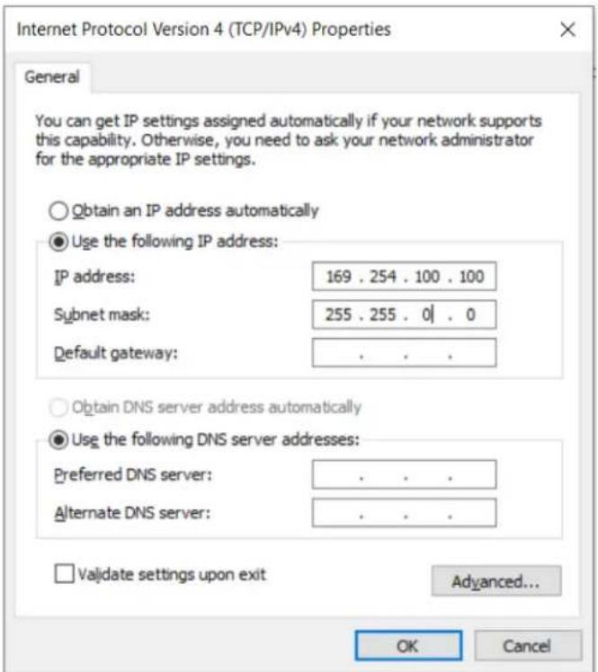
-
Access the device UI using http://169.254.170.187 with default credentials as below:
-
Username: admin
- Password: admin
Device access using DHCP IP address
To access the device using DHCP IP address, follow the below steps:
- Plugin the device to the network.
- Obtain the IP address of the device from the system administrator.
-
Access the device UI using http://
and default credentials, as listed below: -
Username: admin
- Password: admin
LED status
The Enterprise Wi-Fi AP features a single-color LED. The power LED glows amber when AP is turni turns green once the AP has successfully turned on. The network or status LED glows green if t connection to XMS or cnMaestro controller or manager is down. It turns blue once the AP is con successfully to XMS or cnMaestro.
Table 6 Enterprise Wi-Fi AP LED status
| LED Color Status | Indication |
 | The device is turning on. Note:If the LEDs remain amber for more than five minutes, the device has failed to turn on. Note:If the LEDs remain amber for more than five minutes, the device has failed to turn on. |
 | The device is turned on and accessible.The Wi-Fi services are up, if configured. |
 | XMS or cnMaestro connection is successful. |
Onboarding the Device
This chapter describes the following topics:
Overview
• Device Onboarding and Provisioning
Overview
By default, support is available for all the devices at https://cloud.cambiumnetworks.com, no user action is required to direct devices to contact either cnMaestro Cloud or XMS-Cloud. You can onboard and devices without any additional setup.
If you are using cnMaestro On-Premises, you must direct the devices to connect to the cnMaestro using DHCP options or static URL configuration. For more information, refer to the cnMaestro On-Premises User Guide.
Device onboarding and provisioning
Enterprise Wi-Fi APs support the following onboarding methods:
- cnMaestro
• XMS-Cloud
cnMaestro
cnMaestro is a simple next-generation network management system for Cambium Networks wireless ar wired solutions.
For onboarding devices to cnMaestro, refer to the cnMaestro User Guide.
Supported devices and minimum version
The following table lists the minimum release version of every Enterprise Wi-Fi APs that is required managed by cnMaestro Cloud and On-Premises. It also lists the minimum version of cnMaestro Clou On-Premises required to manage the respective APs.

Note
- The AP version is the minimum version required to manage the APs using cnMaestro Cloud, On-Premises, or XMS-Cloud.
• Similarly, the cnMaestro Cloud, On-Premises, and XMS-Cloud versions are the minimum versions required to manage the APs.

Warning
- X7-35X, X7-53X, and X7-55X APs are not supported on XMS-Cloud. They can be managed only on cnMaestro.
- Enterprise Wi-Fi 6 APs (XE and XV series) running Release 7.1 cannot be downgrade version earlier than 6.6.1.
- Release 7.1 will not be available for Wi-Fi 6/6E APs in XMS-Cloud.
Table 7 Supported minimum AP and cnMaestro versions
| AP Model | Supported | Minimum | AP Version | Supported | Minimum | cnMaestro / XMS-Cloud Version | |
| cnMaestro Cloud | cnMaestro On-Premises | XMS-Cloud | cnMaestro Cloud | cnMaestro On-Premises | XMS-Cloud | ||
| XV3-8 | 6.6.0 | 3 6.6.0.3 | 6.6.0.3 Current | 2.4.1 | Current | ||
| XV2-2 | 6.6.0 | 3 6.6.0.3 | 6.6.0.3 Current | 2.4.1 | Current | ||
| XV2-2T0 | 6.6.0.3 | 6.6.0.3 | 6.6.0.3 Current | 3.1.0 | Current | ||
| XV2-2T1 | 6.6.0.3 | 6.6.0.3 | 6.6.0.3 Current | 3.1.1 | Current | ||
| XV2-22H | 6.6.0.3 | 6.6.0.3 | 6.6.0.3 Current | 3.1.1 | Current | ||
| XV2-21X | 6.6.0.3 | 6.6.0.3 NA | Current | 3.1.1 NA | |||
| XV2-23T | 6.6.0.3 | 6.6.0.3 NA | Current | 3.1.1 NA | |||
| XE3-4 | 6.6.0.3 | 6.6.0.3 | 6.6.0.3 Current | 3.1.0 | Current | ||
| XE3-4TN | 6.6.0.3 | 6.6.0.3 | NA | Current | 3.2.0 | CurrentNote: AFC and 6 GHz operation are not supported | |
| XE5-8 | 6.6.0.3 | 6.6.0.3 | 6.6.0.3 | Current | 3.1.1 Current | ||
| X7-35X | 7.0 | 7.0 | NA | Current | 5.1.0 | NA | |
| X7-53X | 7.1 | 7.1 | NA | Current | 5.3.0 | NA | |
| X7-55X | 7.1 | 7.1 | NA | Current | 5.3.0 | NA | |
XMS-Cloud
XMS-Cloud makes it easy to manage networks from a single, powerful dashboard. Zero-touch provision and centralized, multi-tenant network orchestration simplifies network management functions. XMS-Cloud helps manage Cambium Enterprise Wi-Fi devices.
For onboarding devices to XMS-Cloud, refer to https://www.youtube.com/watch?v=qD-nPsdRc4Y.
Configuring the System
This chapter describes the following topics:
- Basic
- Management
- Time settings
- Event Logging
SNMP
Basic
To configure the basic parameters for the AP, complete the following steps:
-
Navigate to Configuration > Wi-Fi Profiles > AP Groups page.
-
Click Add New and select Enterprise Wi-Fi (E-Series, XE/XV/X7-Series) from the Type drop-down list.
By default, the Basic tab is displayed.

Note
- The following special characters are supported when creating the AP Group and WLAN passwords:
- By default, the password is not configured.
You can also change the password after creating it.
$$ a - z A - Z _ {-} ^ {*} \& \% # @! < >. () [ ] ^ {\wedge \sim} 1 2 3 4 5 6 7 8 9 0. $$
Table 8 lists the configurable parameters that are available in the Basic tab in the cnMaestro UI.
Table 8 Basic parameters
| Parameter Description Range Default | |||
| Name Hostname | of the device.Supported maximum length of the hostname: 64 characters | - EnterpriseWi-Fi AP ModelNumber-Last 3 Byt of ESN | |
| Location Location | where the device is placed.Supported maximum length of location: 64 characters | - | - |
| Contact Contact | information for the device. - - | ||
| Country Country | of operation of the device.To be set by the administrator only.The allowed operating channels and the respective power levels depend on the country of operation. countries supported depends on the SKU of the device (FCC and ROW).Note: Radios remain disabled unless this parameter is configured. | -transmitThe list of device (FCC) | |
| Placement Enterprise | prise Wi-Fi AP device supports both Indoor and Outdoor deployments. Based on deployment user can configure it as follows:Indoor: Only indoor channels for configured country code will be available and operational.Outdoor: Only outdoor channels for configured country code will be available and operational. | Outdoor | |
| PoE Output Enable power over Ethernet to an auxiliary device connected to PoE OUT port. | |||
| Dual 5 GHz radio Enable Dual 5 GHz radio.This parameter provides the flexibility of splitting 8x8 5 GHz radio into two 4x4 5 GHz radios. | - Disabled | ||
| LED When enabled, turns on the device LEDs during operation. - | Enabled | ||
| LLDP Advertises device capabilities and information in the L2 network. | - Enabled | ||
| Recommended Channel Distribution | Allows unique distribution of channels across radios multiple radios are configured with same frequency Note: This option is available only as a CLI-based configuration. Use the channels-distribution command. | when enabled band. | |
| Default Power Policy | Provision to configure current power policy. | - Sufficient | |
| Power Force Type | Provision to configure power force type. | - None | |
Figure 4 The AP Groups > Basic page

Power over Ethernet (PoE) in
Enterprise Wi-Fi APs first attempt to detect the type and classification of the Power Source (PS), the being powered by, using standard hardware handshake and control logic. Some PS devices are the type, like the Cambium PoE power injectors, and therefore the AP cannot detect the type or class the PS they are being powered by. For this reason, Enterprise Wi-Fi APs also use LLDP power r
request a specific amount of PoE power from the PS. This feature in the Enterprise Wi-Fi APs is power request and it is enabled by default.
The following table lists the PoE power requirements for the Enterprise Wi-Fi APs:

Caution
Although APs may operate in accordance with the power requirements mentioned in the Hardware Power Requirement column, caution is advised as the results may be unexpected
Table 9 PoE power requirements for APs
| Device PoE | Out Hardware | Power Requirement | Maximum Power Draw (Watts) | Minimum Power Required to boot (Watts) |
| XV3-8 No 8 | 02.3bt 35 22.9 | |||
| XV2-2 No 8 | 02.3at 21 7.6 | |||
| XV2-2T0 Yes | (Max 30W) | 802.3at 51 13.3 | ||
| XV2-2T1 Yes | (Max 30W) | 802.3at 51 13.3 | ||
| XV2-22H Yes | (Max 10W) | 802.3af 22.95 8 | ||
| XV2-21X No | 802.3af 12.95 | 8 | ||
| XV2-23T | No 802.3af | 12.95 | 8 | |
| XE3-4 | No 802.3bt | 32 15.6 | ||
| XE3-4TN | Yes (Max 30W) | 802.3at 64 15 | ||
| XE5-8 | No 802.3bt | 60 | 32.9 | |
| X7-35X | No 802.3at | 25 | 12 |

Note
Accurate time on the AP is critical for features such as WLAN Scheduled
Access and :
Figure 5 Power policy configuration

Table 10 lists the Cambium PoE injectors and cnMatrix models supported on the APs.
Table 10 Supported Cambium PoE Injectors and cnMatrix models
| AP Model | Cambium PoE Injector cnMatrix | Recommended Model |
| XV3-8 N000000L142A | EX3028R-P / EX3052R-P | / EX2016M-P |
| XV2-2 N000000L142A | EX3028R-P / EX3052R-P | / EX2016M-P |
| XV2-2T0 N000000L142A | EX3028R-P / EX3052R-P | / EX2016M-P |
| XV2-2T1 N000000L142A | EX3028R-P / EX3052R-P | / EX2016M-P |
| XV2-22H N000000L142A | / N000000L034B | EX3028R-P / EX3052R-P / EX2016M-P / EX2052-P / EX2052R-P / EX2028-P / P / EX1028-P / EX1010-P |
| XV2-21X N000000L142A | / N000000L034B / N000900L017A | EX3028R-P / EX3052R-P / EX2016M-P / EX2052-P / EX2052R-P / EX2028-P / P / EX1028-P / EX1010-P |
| XV2-23T N000000L142A | / N000000L034B / N000900L017A | EX3028R-P / EX3052R-P / EX2016M-P / EX2052-P / EX2052R-P / EX2028-P / P / EX1028-P / EX101O-P |
| XE3-4 N000000L142A | EX3028R-P / EX3052R-P | / EX2016M-P |
| XE3-4TN N000000L142A | EX3028R-P / EX3052R-P | / EX2016M-P |
| XE5-8 N000000L142A | EX3028R-P / EX3052R-P | / EX2016M-P |
| X7-35X | N000000L142A | EX3028R-P / EX3052R-P / EX2016M-P |

Attention
Configure Power policy and power force type based on the input power source.
Power over Ethernet (PoE) Out port
PoE out provision is provided to power on devices that are compatible with IEEE 802.3 af/at PoE power consumption or Cambium 30V POE as shown in the below table.
Table 11 PoE-out capabilities
| AP | Model | 10W | 48V | @ | 15W | 48V | @ | 30W | 30V | @ | 30W | Default | State |
Figure 6 PoE Output cnMaestro configuration
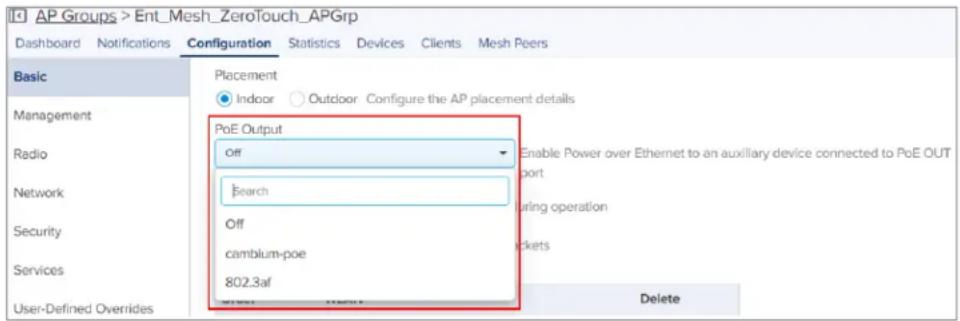
Link Layer Discovery Protocol (LLDP)
LLDP is a Layer 2 network protocol used to share information, such as the device manufacturer, r network capabilities, and IP address with other directly connected network devices. APs can both act their presence by sending LLDP announcements and can also collect and display information sent by neighbors.
LLDP settings are enabled by default on the AP. This implies that the power negotiation is also LLDP when an AP is powered by a Power over Ethernet (PoE) PSE switch port.
This window allows you to establish your LLDP settings.
Power negotiation
LLDP discovers a device port (connected to a PoE PSE switch, for example) that supplies power t. The AP checks that the port can supply the maximum power that is required by the AP model. the required maximum power (in watts) via LLDP frames to the PoE source and expects the PoE reply with the amount of power that can be allocated.
- If the AP receives a response confirming that the power allocated by the PoE PSE source is greater than the maximum power requested, the AP enables radios and other Model Specific peripherals (for example, USB port, Bluetooth).
-
If the AP receives a power allocation that is less than the maximum but more than the minimum to keep the radios operational, the AP issues a Syslog message and shuts down the other port (for example, USB port, Bluetooth).
-
If the AP receives less than the minimum power required for the radios to operate, the radios down for five minutes. During this time, LLDP power negotiation continues to monitor the available power to ensure it meets the minimum requirement for the AP radios to function.
- Click to check power status: show power
This provides a more graceful way of handling an underpowered situation on a Wi-Fi device. When radios are turned off, XMS can notify you so that you don't have to hunt down an intermittent
CLI Configuration
Consider the following tasks to configure the CLI:
To enable:
ap(config)# lldp
ap(config)#
To disable:
ap(config)# no lldp
ap(config)#
To list LLDP configuration:
show lldp configuration
show lldp interfaces
Request power
To enable/disable power negotiation via LLDP:
ap(config)# lldp
request-power : Enable power negotiation (default:enabled)
tx-hold : Set transmit hold multiplier (default:4, used to calculate the time-to-live (tx-interval * tx-hold))
tx-interval : Set LLDP packet transmit delay (in Sec, default:30 sec)
ap(config)# lldp request-power
<ENTER>
ap(config)# lldp request-power
Transmit hold
It is used to compute the Time To Live (TTL) value. This is the time during which the receiving maintains information before the validity of information expires.
ap(config)# lldp
request-power : Enable power negotiation (default:enabled)
tx-hold : Set transmit hold multiplier (default:4, used to calculate the time-to-live (tx-interval * tx-hold))
tx-interval : Set LLDP packet transmit delay (in Sec, default:30 sec)
ap(config)# lldp tx-hold
Specify transmit hold multiplier value (max 65535)
Transmit interval
It is the time interval between two regular LLDP packets transmissions. The AP sends out LLDP announcements, advertising its presence at this interval. The default value is 120 seconds.
ap(config)# lldp
request-power : Enable power negotiation (default:enabled)
tx-hold : Set transmit hold multiplier (default:4, used to calculate the time-to-live (tx-interval * tx-hold))
tx-interval : Set LLDP packet transmit delay (in Sec, default:30 sec)
ap(config)# lldp tx-interval
Specify LLDP transmit delay in sec (max 65535)
Management
Administrator Access
To configure Administrator access parameters, complete the following steps:
-
Navigate to Configuration > Wi-Fi Profiles > AP Groups page.
-
Click Add New and select Enterprise Wi-Fi (E-Series, XE/XV/X7-Series) from the Type drop-down list.
-
Click Management tab > Administrator Access section.
Table 12 lists configurable fields that are displayed in the Administrator Access section.
Table 12 Administrator Access parameters
| Parameter | Description Range Default | ||
| Admin Password | Password for authentication of UI and CLI sessions. - admin | ||
| Telnet Enables | Telenet access to the device CLI. - Disabled | ||
| SSH Enables | SSH access to the device CLI. | - Enabled | |
| SSH Key | Provision to login to device using SSH Keys. The user is Delated to public key in this section. If configured, the user has using Private Keys. This is applicable for both CLI and GUI. | - Delated to login to API. | - Delated to app adding to API. |
| HTTP | Enables HTTP access to the device UI. | - Enabled | |
| HTTP Port | Provision to configure HTTP port number to access device UI. | 1-65535 | 80 |
| HTTPS | Enables HTTPS access to the device UI. | - Enabled | |
| HTTPS Port | Provision to configure HTTPS port number to access device UI. | 1-65535 | 443 |
| RADIUS Mgmt Auth | User has provision to control login to AP using RADIUS- Disabled authentication. If enabled, every credential that is provided by the user undergo RADIUS authentication. If successful, allowed to login to UI of the device. This is applicable for both CLI and GUI. | ||
| RADIUS Server | Provision to configure RADIUS IPv4 server for Management Authentication. | - | |
| RADIUS Secret | Provision to configure RADIUS shared secret for Management authentication. | - |
Figure 7 Administrator Access page

HTTPS Proxy server configuration
The proxy management service is established in the AP to proxy management of traffic for remote management services originating from the AP.
For zero-touch configuration, refer to DHCP Option 43 - Zero-touch onboarding.
CLI Configuration:
ap(config)# management proxy
https : Enable HTTPS proxy support
ap(config)# management proxy https
host : Configure HTTPS proxy host
password : Configure HTTPS proxy password
port : Configure HTTPS proxy port
username : Configure HTTPS proxy username
Time settings
User can configure up to two NTP servers. These are used by the AP to set its internal clock time zones configured on the device. While powering ON the AP, the clock resets to default and time as the Enterprise Wi-Fi AP does not have battery backup. The servers can be specified as or as a hostname (For example, pool.ntp.org). If NTP is not configured on the device, the device synchronizes the time with cnMaestro if onboarded.
To configure time parameters, complete the following steps:
-
Navigate to Configuration > Wi-Fi Profiles > AP Groups page.
-
Click Add New and select Enterprise Wi-Fi (E-Series, XE/XV/X7-Series) from the Type drop-down list.
-
Click Management tab > Time Settings section.
Table 12 lists configurable fields that are displayed in the Time Settings section.
Table 13 Time Setting parameters
| Parameter Description Range Default | |||
Time zone The time zone can be set according to the location where the is installed. Selecting the appropriate time zone from down list ensures that the device clock is synced with the clock time. | NoteAccurate time on the AP is critical for features such as WLAN Scheduled Access and Syslogs. | where the the drop-wall wall | |
| NTP Server 1 | Name or IPv4 address of Network Time Protocol server 1. - | - | |
| NTP Server 2 | Name or IPv4 address of Network Time Protocol server 2. | - - | |
Figure 8 Time setting page

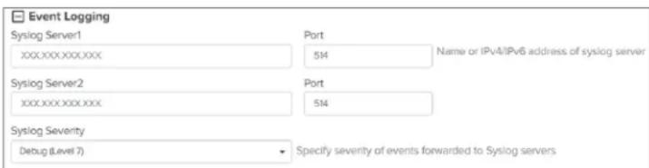
Event logging
The Enterprise Wi-Fi AP devices support multiple troubleshooting methods. Event logging or Syslog is of the standard troubleshooting processes. If you have a Syslog server in your network, you can an Enterprise Wi-Fi AP device. A maximum of two Syslog servers can be configured on an Enterprise AP device. Events are sent to both configured Syslog servers if they are up and running.
To configure event logging, complete the following steps:
- Navigate to Configuration > Wi-Fi Profiles > AP Groups page.
- Click Add New and select Enterprise Wi-Fi (E-Series, XE/XV/X7-Series) from the Type drop-down list.
- Click Management tab > Event Logging section.
Table 14 lists configurable fields that are displayed in the Event Logging section.
Table 14 Event logging parameters
| Parameter | Description Range Default | ||
| Syslog Server 1 | Hostname or IPv4 address of the Syslog server and respective number. | spec514 | port |
| Syslog Server 2 | Hostname or IPv4 address of the Syslog server and respective number. | spec514 | port |
| Syslog Severity | Provision to configure severity of Logs that must be forwarded server. The Log levels supported are as per RFC. | warDebugo | the |
Figure 9 Event logging page
SNMP
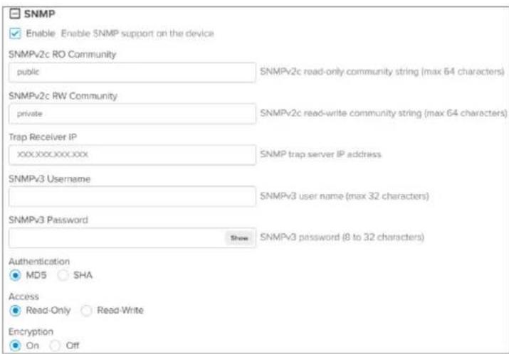
To configure SNMP, complete the following steps:
- Navigate to Configuration >Wi-Fi Profiles >AP Groups page.
- Click Add New and select Enterprise Wi-Fi (E-Series, XE/XV/X7-Series) from the Type drop-down list.
- Click Management tab > SNMP section.
Table 14 lists configurable fields that are displayed in the SNMP section.
Table 15 SNMP parameters
| Parameter Description Range Default | |||
| Enable Provision | to enable SNMPv2 or SNMPv3 support on the device - - | ||
| SNMPv2c RO community | SNMP v2c read-only community string. - public | ||
| SNMPv2c RW community | SNMP v2c read-write community string. - private | ||
| Trap Receiver IP Provision to configure SNMP trap receiver IPv4 server. - - | |||
| SNMPv3 Username | Enter the username for SNMPv3. - - | ||
| SNMPv3 Password | Enter the password for SNMPv3. - - | ||
| Authentication Provision to choose the authentication type as MD5 or SHA. - MD5 | |||
| Access | Provision to choose Access type as read-only or read-write. | - | RO |
| Encryption | Choose ON or OFF. APs use the AES algorithm for encryption. | - | ON |

Note
The AP uses the AES-128 algorithm for encryption. It uses the SNMPv3 password configuration parameter for encryption and authentication.
Figure 10 SNMP parameters
Configuring the Radio
This chapter describes the following topics:
- Overview
- Configuring Radio parameters
- BSS coloring
• Target Wake Time (TWT) - Receive sensitivity configuration
• Multicast-snooping and Multicast-to-Unicast conversion - Boot loop detection
Overview
Enterprise Wi-Fi AP devices support numerous configurable radio parameters to enhance the quality of service according to the deployment.
Configuring Radio parameters
The XV3-8 Tri-Band Indoor Wi-Fi 6 AP can operate in either Dual Band Simultaneous (DBS) or Sir Simultaneous (SBS). This feature provides the flexibility of splitting 5 GHz radio into two independent configurable and operational radios. In DBS mode, 5 GHz radio operates as single radio with an 8 configuration. In SBS mode, 5 GHz Radio operates as split radio with each 4x4 configuration. Confir parameters under the Radio profile are listed below.
- Basic
• Software-Defined Radio (SDR) capabilities
• Enhanced Roaming
Basic
To configure radio parameters, complete the following steps:
- Navigate to Configuration > Wi-Fi Profiles > AP Groups page.
- Click Add New and select Enterprise Wi-Fi (E-Series, XE/XV/X7-Series) from the Type drop-down list.
- Click Radio tab > Basic section.
Table 16 lists the configurable fields that are displayed in the Radio > Basic section.
Table 16 Configure Radio parameters
| Parameter | Description Range Default | ||
| Radio | |||
| Enable Enables the operation of radio. - Enabled | |||
| Band Select the appropriate radio band, if the radiosupportsmultiple bands. | - | ||
| Channel Select the channel from the drop-down list. Channel the drop-down list are populated based on the configured. | Wi-Fin 7 APscountry2.4 GHz: 15 GHz: 36-64, 100 - 144,and 149 - 1656 GHz: 1 -233Wi-Fi 6/6E APs2.4 GHz: 1 - 145 GHz: 36-1736 GHz: 1 -233 | Auto- 13-144,165 | |
| Channel Width | Specifies the channel widths for the operation. following widths are supported:For 2.4 GHz: Only 20 MHz channel width supported.For 5 GHz: 20 MHz, 40 MHz, 80 MHz, channel widths are supported.For 6 GHz: 20 MHz, 40 MHz, 80 MHz, 320 MHz channel widths are supported. Note320 MHz width is supported on the X7-35XAP only and can be configured only usingthe channel-width CLI command.ap(config)# wireless radio<1-3>ap(config-radio-3)# channel-width 320 Note320 MHz width is supported on the X7-35XAP only and can be configured only usingthe channel-width CLI command.ap(config)# wireless radio<1-3>ap(config-radio-3)# channel-width 320 | 2.4GHz:20MHz5GHz:40MHz6GHz:80MHz | |
| Transmit Power | Total conducted transmit power, in decibel-milliwatt(dBm), of each radio based on coverage and maximum transmit power of Enterprise Wi-Fi AP varies based on model number.Details of transmit power supported by each Enterprise Wi-Fi AP device are available athttps://www.cambiumnetworks.com/products/wifi/.Transmit power varies as per the country where the AP is deployed.. The default value is AUTO, which means radio transmit power is configured to the maximum as per the county configured. | • 2.4 GHz: 4 SLA.30The devices• 5 GHz: 4 to 30EnterpriseGHz: 4 to 30 | Auto |
| Beacon Interval | Specifies the time duration (in milliseconds) between consecutive Beacons. | 50ms two 3400ms | 100 |
| Minimum Unicast rate | Specifies the coverage area of the Enterprise device. The higher the rate selected, the lesser and the 802.11g. data You can configure this value based on the SLAates the deployment. The drop-down list contains all values advertised by Enterprise Wi-Fi AP devices, including legacy, HE, HT, and VHT rates. | Wi-Fi 802.11b | 1Mbps |
| Candidate Channels | Specifies selective channels based on user required. Options vary based on a band of operation and follows:For 2.4 GHz:AllSpecificFor 5 GHz:AllSpecificPrefer Non-DFSPrefer DFSFor 6 GHz:AllSpecific | Wi-Fi 7 APs• 2.4 GHz: 1• 5 GHz: 36 - 64, 100 - 144, and 149 - 165• 6 GHz: 1 -233Wi-Fi 6/6E APs• 2.4 GHz: 1• 5 GHz: 36 - 173• 6 GHz: 1 -233 | All- 13- 14- |
| Mode All | Enterprise Wi-Fi AP devices support either 802.11ac 802.11ac Wave 1, or 802.11ac Wave 2, or 802.11be. Some legacy clients might not work as expected; therefore, this parameter can be tuned for backward compatibility based on wireless clients. NoteYou can configure the be or ax-be mode by using the mode CLI commandap(config)# wireless radio <1-3>ap(config-radio-3)# mode be NoteYou can configure the be or ax-be mode by using the mode CLI commandap(config)# wireless radio <1-3>ap(config-radio-3)# mode be | Wi-Fi 7 APs11be. Some GHz: b/g/n/ax/be5 GHz: a/n/ac/ax/beradio6 GHz: ax/be only:Wi-Fi 6/6E APs2.4 GHz: b/g/n/ax5 GHz: a/n/ac/ax | All mode |
| Short Guard Interval | Standard 802.11 parameter to increase the through an Enterprise Wi-Fi AP device. | ghpEnabled | |
| Off Channel Scan (OCS) | |||
| Enable Provision to enable OCS on a device to capture clients and APs. | neighbor | - | |
| Dwell-time | Configure the time period to spend scanning of devices on a channel. | 50+300 50ms | |
| Auto-RF (Dynamic Power) | |||
| Enable Enable or disable dynamic power management. - - | |||
| Mode Select | the required dynamic power modes. Two modes are supported:By-ChannelBy-Band | des By- | Channel |
| Minimum Transmit Power | The minimum transmit power that the AP can radio when adjusting automatic cell sizes | 5st5gndBm 8 dBm | |
| Minimum Neighbour Threshold | The minimum number of neighbors to consider reduction by automatic cell logic. | 100 power | |
| Cellsize Overlap Threshold | Cell overlap will be allowed when the AP is automatic cell sizes. | determining% | |
| Auto-RF (Dynamic Channel) | |||
| Enable Enable or disable the Dynamic Channel auto-RF functionality. | Disabled | ||
| Packet Error Rate | Enable channel change using unsuccessful packet transmissions by the AP. | ||
| Packet Error Rate Threshold | Specifies the packet error rate threshold in percentage 30 (%). | ||
| Number of Packet Error Rate samples | Specifies the number of packet error rate samples needed to trigger a channel switch. | 120 40 | |
| Channel Utilization | Enable channel change using the channel efficiency. | ||
| Channel Utilization Threshold | Specifies the channel utilization threshold in percentage 70 (%). | ||
| Number of Channel Utilization samples | Specifies the number of channel utilization samples needed to trigger a channel switch. | 5300 100 | |
| Noise Enable channel change with higher noise. | |||
| Noise Threshold | Specifies the noise threshold in dBm. -70 to -90 dBm -70 | ||
| Number of Noise samples | Specifies the number of noise samples needed a channel switch. | 5120 trigger | |
| Auto-RF Iterations | Specifies the number of times the Auto-RF channel change function must run, at the configured frequency, before stopping.The iteration count resets when the AP restarts or when the radio resets.The default value is 0. It indicates that the Auto-RF channel change function will run at the frequency configured in either of the following parameters stopping:Enable time range for Auto-RFChannel Hold TimeNoteWhen the AP exceeds the configured iteration count, the Dynamic Channel Selection (DCS) method of channel selection takes over.For more information on Auto-RF, see Auto-RF. | 0-400 | |
| Samples Specifics the minimum number of samples required run the channel selection. | 1-20 3 | ||
| Enable time range for Auto-RF | Specifies the time range (in the 24 hour format) at which the Auto-RF channel change function must run When enabled, select the start and end time. | at which everyday. | |
| Channel Hold Time | Specifies the time (in minutes) for which the AP must start and the channel. | must start and minutes for APs running version 6.6.0.1 and later• 1-4320 minutes for APs running versions earlier than 6.6.0.1. | 1440 |
To configure Auto-RF (Dynamic Channel) using the CLI, execute the following commands:
ap(config-radio-1)# auto-rf dynamic-channel
acceptance-per-threshold : Configure Acceptance Packet Error Rate (PER) threshold
channel-hold-time : specifies how much time AP needs to hold the channel. Default is 1440 mins
cmbnbr-minsnr : Configure the cambium neighbour minimum SNR to consider as part of autorf cambium neighbour factor
congestion-channel-switch : Enable / Disable Congestion based channel switch, disabled by default
congestion-threshold : Configure Congestion threshold
count : Configure number of times autorf need to run;
'0' disables this feature
dcs-monitor-interval : Configure dcs monitor interval in minutes.
dcs-trigger-threshold : Configure dcs trigger threshold percentage
per-channel-switch : Enable / Disable PER based channel switch,
disabled by default
samples : Configure the minimum number of samples
required to run the channel selection
schedule-time : Configure time range (24 hour format) at which
autorf algorithm need to run everyday
weightage-map-index : Configure weightage map index
To configure Auto-RF (Dynamic Power) using the CLI, execute the following commands:
ap(config-radio-1)# auto-rf dynamic-power
cellsize-overlap-threshold : Cell overlap that will be allowed when the AP is determining automatic cell sizes
maximum-transmit-power : Maximum transmit power that the AP can assign to a radio when adjusting automatic cell sizes
minimum-neighbor-threshold : The Minimum number of neighbors to consider for power reduction by autocell logic
minimum-transmit-power : Minimum transmit power that the AP can assign to a radio when adjusting automatic cell sizes
mode : Set dynamic power mode by-channel/by-band
Figure 11 Radio parameters in the Basic page
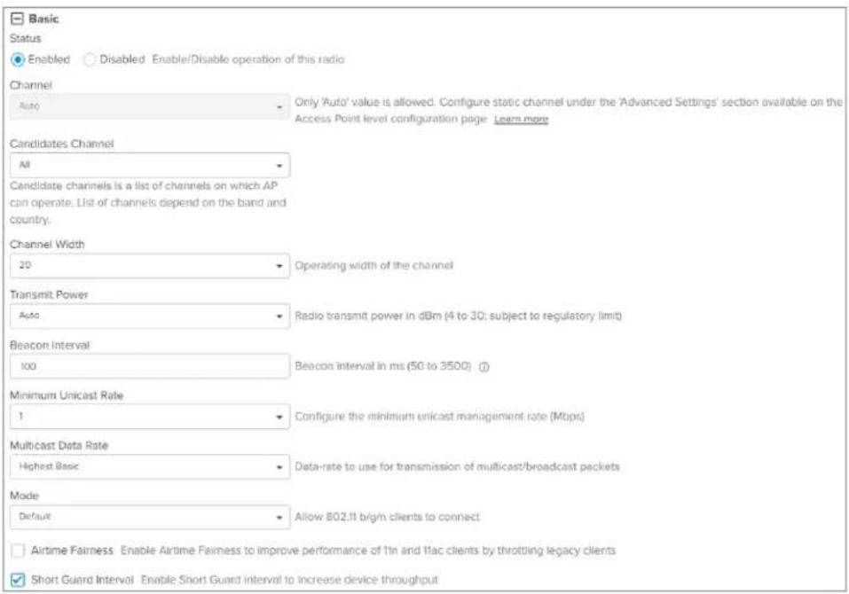
Figure 12 Channel Scan - Off Channel Scan option

Figure 13 Channel Scan - Continuous Background Scan option

Figure 14 Auto-RF - Dynamic Channel
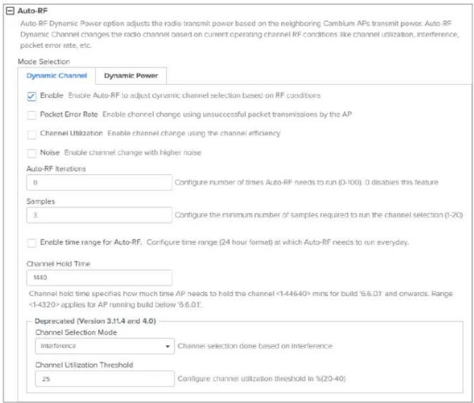
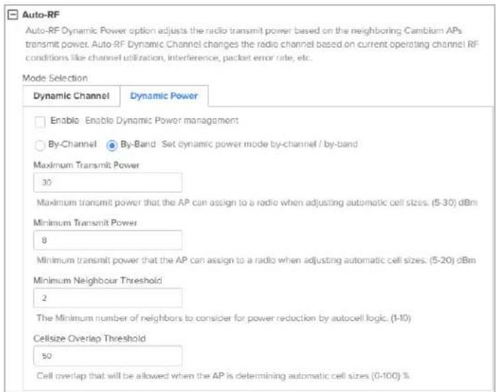
Figure 15 Auto-RF - Dynamic Power
Software-Defined Radio (SDR) capabilities

Note
- In XV3-8, radio 3 is available only in the SBS mode.
- In XE5-8, radio 5 is available only in the SBS mode.
Table 17 Supported radios
| Access Point Model | Radio 1 (2.4 GHz) | Radio 2 Radio 3 Radio 4 | (5 GHz) | Radio 5 (5 GHz) | |||
| XV3-8 | √ | √ (DBS) | √ (SBS) | ||||
| XV2-2 | √ | √ | |||||
| XV2-2T0 | √ | √ | |||||
| XV2-2T1 | √ | √ | |||||
| XE3-4 | √ √ | √ √ | |||||
| XE3-4TN | √ √ | √ √ | |||||
| XE5-8 | √ √ | √ √ √ | √ | (DBS) | √ (SBS) | ||
| XV2-21X | √ | √ | |||||
| XV2-23T | √ | √ | |||||
| XV2-22H | √ | √ | |||||
GHz 6 GI
Table 18 Factory reset behavior of multi-radio APs
| Access Point Model | Radio 1 (2.4 GHz) | Radio 2 Radio | o 3 Radio 4 | (5 GHz) | Radio 5 (5 GHz) | ||
| 5 GHz | 6 GHz | 5 GHz | 6 GHz | ||||
| XV3-8 | ON | ON | NA | OFF | NA | - | - |
| XE3-4 | ON | ON | NA | OFF | ON | - | - |
| XE3-4TN | ON | ON | NA | OFF | ON | - | - |
| XE5-8 | ON | ON | OFF | OFF | ON | ON4x4 SBS | ON4x4 SBS |
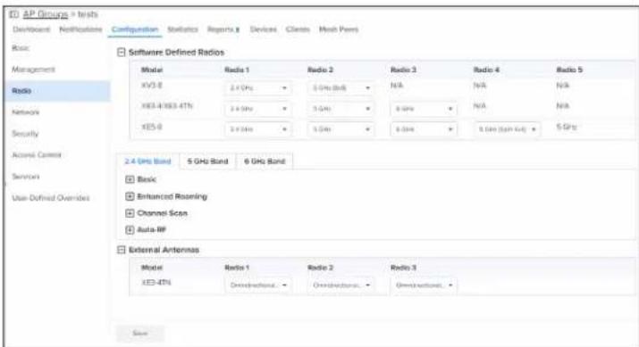
The Radio page allows the user to enable or disable the Software-Defined Radio (SDR) operations. It allows to configure Software Defined Radios, Basic, Enhanced Roaming, Off Channel Scan, Auto-RF, and External Antennas.

Note
The software-defined radio creation and channel listing are populated based on the count specific restrictions, device type, and release version.
Software-Defined Radio
Software-Defined Radio (SDR) allows you to configure radio parameters for XV3-8, XE3-4, XE3-4TN, an XE5-8 device models. By default these device models are configured for radio bands as shown in figure. The other radio bands for which the devices can be configured are as shown in Table 19
Table 19 Supported Radio bands for Enterprise Wi-Fi Series (XE, XV-Series)
| Models | Radios Supported Radio Bands | Channel Specification | ||||||||
| Channel width | Default Channel width | Supported channel list | ||||||||
| XV3-8 | Radio 1 2.4 GHz | 20/40 20 1 to 13 | ||||||||
| Radio 2 5 | GHz (8x8 - single radio) or 5 GHz(Split 4x4 dual radio) | 20 / 40 | / 80 40 | 100 to 36 to 165 in in 8x8 Split 4x4 single dual radio | ||||||
| Radio 3 20 | / 40 / 80 40 | 36 to | 64 | in Split 4x4 dual radio | ||||||
| Models | Radios Supported | Radio Bands | Channel Specification | ||
| Channel width | Default Channel width | Supported channel list | |||
| XE3-4 | Radio 1 2.4 GHz 2 | 0/40 20 1 to 13 | |||
| Radio 2 5 | GHz 20 / 40 / | 80 40 36 | to 64 | ||
| Radio 3 5 | GHz 20 / 40 / | 80 / 160 | 40 100 | to 165 | |
| 6 GHz | 160 | Any 6 GHz channel | |||
| XE3-4TN | Radio 1 | 2.4 GHz | 20/40 | 20 | 1 to 13 |
| Radio 2 5 | GHz 20 / 40 / | 80 40 | 36 to 64 | ||
| Radio 3 5 | GHz 20 / 40 / | 80 / 160 | 40 100 | to 165 | |
| 6 GHz | 160 | Any 6 GHz channel | |||
| XE5-8 | Radio 1 2.4 | GHz 20/40 20 | 1 to 13 | ||
| Radio 2 | 5 GHz or 6 | GHz 20 / 160 | / 20/80** 80 | Refer to Table 20 for supported channel list in 5 GHz and 6 GHz. | |
| Radio 3 | 5 GHz or 6 | GHz 20 / 160 | / 20/80** 80 | ||
| Radio 4 | 5 GHz (8x8 - radio) or 5 GHz (Split 4x4 dual radio) | 20ngle 40 Hz | / 80 20 / 80 | ||
| Radio 5 | 20 / 40 | ||||
| * 5 GHz **6 GHz | |||||

Note:
- Split 4x4 is supported only on APs that support 8x8 spatial streams. Supported APs are XV3-8 and XE5-8.
- Dual 5 GHz Radio (Only supported on XV3-8 and XE5-8 APs) Splits 8x8 5 GHz radio into two 4x4 5 GHz radios.
Table 20 Supported Channel list 5 GHz or 6 GHz in XE5-8
| Radio Index | Radio 1 | Radio 2 | Radio 3 | Radio 4 | Radio 5 | ||
| 8x8 mode of operation: Radio 4 & 5 as single radio with 8x8 | |||||||
| Radio 2 | Radio 3 | Radio 4 and 5 | |||||
| Radio Index Radio 1 Radio 2 Radio 3 Radio | 4 | Radio 5 | ||||||
| 5 GHz | 5 GHz 5 | GHz NA 100 to | 128 149 | to 165 36 | to 64 | |||
| 6 GHz | 5 GHz 5 | GHz NA Any 6 | GHz | channel | 100 to 165 | 36 to 64 | ||
| 5 GHz | 6 GHz 5 | GHz NA 100 to | 165 Any | 6 GHz | channel | 36 to 64 | ||
| 6 GHz | 6 GHz 5 | GHz NA * 1 | to 93 | ** 97 to | 233 / 65 to | 36 to 165 93 | ||
| Split 4x4 mode of operation: Radio 4 and 5 as individual radio with 4x4 | ||||||||
| Radio 2 | Radio | 3 Radio | 4 Radio | 5 | ||||
| 5 GHz | 5 GHz | 5 GHz | 5 GHz | NA | 60 to 64 | 100 to 128 | 149 to 165 | 36 to 40 |
| 6 GHz | 5 GHz | 5 GHz | 5 GHz | NA | Any 6 GHz channel | 100 to 128 | 149 to 165 | 36 to 64 |
| 5 GHz | 6 GHz | 5 GHz | 5 GHz | NA | 100 to 128 | Any 6 GHz channel | 149 to 165 | 36 to 64 |
| 6 GHz | 6 GHz | 5 GHz | 5 GHz | NA | * 1 to 93 | ** 97 to 233 | 100 to 165 | 36 to 64 |
| Note: *FCC SKU 6GHz UNII-5 or 6 (1 - 93) EU SKU UNII-5 low (1 - 61)**FCC SKU 6GHz UNII-7 or 8 (97 - 233) EU SKU UNII-5 High (65 - 93) | ||||||||

Note
You can use the no channels-distribution global configuration CLI command for all multi-radio platforms, such as XE3-4, XE3-4TN, and XE5-8 APs. When configured on device, default channel list can be overridden.
Off Channel Scan (OCS)
The following figure illustrates how to configure Off Channel Scan using the CLI:
ap(config)# wireless radio 2
ap(config-radio-2)# off-channel-scan

dwell-time : Configure Off-Channel-Scan dwelltime
interval : Configure Off-Channel-Scan interval
type : Configure active/passive Off-Channel-Scan
ap(config-radio-2)# off-channel-scan type
active : active off channel scan
passive : passive off channel scan
Table 21 lists the fields that are required for configuring Off Channel Scan:
Table 21 Configuring Off Channel Scan
| Parameter | Description Range Default | ||
| dwell time | Provision to configure Off Channel Scan dwell time. Need 100 or more than 100+ ms for supporting passive scan | 50-300ch method. | 50ges |
Enhanced Roaming
Table 22 lists configurable fields that are displayed in the Radio > Enhanced Roaming tab.
Table 22 Configuring Radio >Enhanced Roaming parameters
| Parameter | Description Range Default | ||
| Enhanced Roaming | |||
| Enable Provision to enable enhanced roaming on device. - Disabled | |||
| Roam SNR threshold | Enterprise Wi-Fi AP device triggers de-authentication of the 100-wireless station when the wireless station is seen at configured below. | SNR level or | |

BSS Coloring
Multiple APs operate on a shared channel by mitigating co-channel interference. This is achieved that spatial reuse technique known as BSS Coloring, which enables devices in one BSS to ignore frame other BSSs on the same channel that are typically some distance away.
Target Wake Time (TWT)
The Target Wake Time (TWT) feature, included in the IEEE 802.11ax amendment, provides a mechan schedule transmissions at a specific time or set of times for individual STAs to wake to exchange AP. Using TWT, each STA negotiates awake periods with the AP to transmit and receive data packet
allowing the STA to go to doze mode to minimize energy consumption and reduce contention with basic service set (BSS).

Note
By default, BSS coloring and TWT are enabled.
Receive sensitivity configuration
This feature allows users to configure the receiver sensitivity per radio. The configuration hooks are exposed from both CLI and XMS-Cloud. cnMaestro does not expose any hooks for configuring receiver configuration. Receiver configuration determines the signal power required at the receiver to achieve targeted or configured bit rate. Every RF receiver comes with a default sensitivity, which may not sufficient for achieving the required RF performance in terms of meeting the bit rate. Therefore, reconfiguration of receiver sensitivity is suggested.
Multicast-snooping and Multicast-to-Unicast conversion
Multicast-to-Unicast conversion heavily depends on multicast (IGMP) snooping. With IGMP snooping enabled, the device monitors IGMP traffic on the network and forwards multicast traffic to only the downstream interfaces that are connected to interested receivers. The device conserves bandwidth by sending multicast traffic only to clients connected to devices that receive the traffic (instead of floor traffic to all the downstream clients in a VLAN).
The functionality to preserve both multicast and unicast MAC addresses during multicast enhancement implementation for packets in APs is introduced. The AP supports Directed Multicast Services (DMS) Multicast Enhancement (ME). ME is a feature provided in APs that allows multicast frames to be set unicast frames to each member of the mentioned multicast group to improve the QoS of the transaction between the STA and the AP. The multicast frame is received at the host WLAN driver as an 8 frame. This frame header contains the destination and source address, which are the multicast group address and client address, respectively. Iteratively, the Ethernet header is replaced with the unicast addresses of the clients present in the multicast group and sent out to the "air". During this process, multicast group address is completely lost from the frame.
CLI Configuration:
| Bridge Snooping Hash Table -- IPv4 | ||||
| NUM GROUP | FDB | PORT | AGE | |
| IPv4 Router Ports: None | ||||
| Bridge Snooping Hash Table -- IPv6 | ||||
| NUM GROUP | FDB | PORT | AGE | |
| IPv6 Router Ports: None XV3-8-EC7708(config)# service show mcastsnoop br0 acltbl | ||||
| IGMP ACL TABLE: PATTEN 01:224.000.000.001/255.255.255.255 - 00:00:00:00:00:00:00:00:00:00:00 -- SYSTEM WIDE MANAGEMENT PATTEN 02:224.000.000.000/255.255.000.000 - 00:00:00:00:00:00:00:00:00:00:00:00 -- MANAGEMENT PATTEN 03:239.255.000.000/255.255.000.000 - 00:00:00:00:00:00:00:00:00:00:00:00 -- MANAGEMENT PATTEN 04:239.255.255.250/255.255.255.255 - 00:00:00:00:00:00:00:00:00:00:00:00 -- NON SNOOPING PATTEN 05:224.000.000.251/255.255.255.255 - 00:00:00:00:00:00:00:00:00:00:00:00 -- NON SNOOPING PATTEN 06:224.000.000.252/255.255.255.255 - 00:00:00:00:00:00:00:00:00:00:00--NON SNOOPING PATTEN 07:000.000.00, 1, 1, 1, 1, 1, 1, 1, 1, 1, 1, 1, 1, 1, 1, 1, 1, 1, 1, 1, 1, 1, 1, 1, 1, 1, 1, 1, 1, 1, 1, 1, 1, 1, 1 | ||||
| MLD ACL TABLE: PATTEN 1:fffO1:ccccc:ccccc:ccccc:ccccc:ccccc:ccccc:ccccc:ccccc:ccccc:ccccc:ccccc:ccccc:ccccc:ccccc:ccccc:ccccc:ccccc:ccccc:ccccc:ccccc:ccccc:ccccc:ccccc:ccccc:ccccc:ccccc:ccccc:ccccc:ccccc:ccccc:ccccc:ccccc:ccccc:ccccc;CCccc;CCccc;CCccc;CCccc;CCccc;CCccc;CCccc;CCccc;CCccc;CCccc;CCccc;CCccc;CCccc;CCccc;CCccc;CCccc;CCccc;CCccc;CCccc;CCccc;CCccc;CCccc;CCccc;CCccc;CCccc;CCccc;CCccc;CCccc;CCccc;CCccc;CCccc;CCccc;CCccc;CCc;CCc;CCc;CCc;CCc;CCc;CCc;CCc;CCc;CCc;CCc;CCc;CCc;CCc;CCc;CCc;CCc;CCc;CCc;CCc;CCc;CCc;CCc;CCc;CCc;CCc;CCc;CCc;CCc;CCc;CCc;CCc;CCc;CCc ; CCccc; CCccc; CCccc; CCccc; CCccc; CCccc; CCccc; CCccc; CCccc; CCccc; CCccc; CCccc; CCccc; CCccc; CCccc; CCccc; CCccc; CCccc; CCccc; CCccc; CCccc; CCccc; CCccc; CCccc; CCccc; CCccc; CCccc; CCccc; CCccc; CCccc; CCccc; CCccc; CCccc; CCccc; CCCCACCT PATTEN 13:fffO1:ccccc:ccccc:ccccc:ccccc:ccccc:ccccc:ccccc:ccccc:ccccc:ccccc:ccccc:ccccc:ccccc:ccccc : c c c c c c c c c c c c c c c c c c c c c c c c c c c c c c c c c c c c c c c c c c c c c c c c c c c c c c c c c c c c c c c c c c c c c c c c c c c c c c c c c c c c c c c c c c c c c c c c c c c c | ||||
ap(config)# multicast-snoop
ap(config)# no multicast-snoop
ap(config)# save
ap(config)# wireless radio 1
ap(config-radio-1)# multicast-to-unicast
ap(config-radio-1)# multicast-to-unicast mode 802.3
ap(config-radio-1)# multicast-to-unicast mode amsdu
ap(config-radio-1)# multicast-to-unicast exclude-list 224.0.0.1
ap(config-radio-1)# show wireless radios multicast-to-unicast

RADIO BAND MC2UC MC2UC-MODE EXCLUDE-LIST

radio1 2.4GHz NO amsdu
radio2 5GHz YES amsdu
ap(config-radio-1)#
Boot loop detection
When an AP turns off thrice due to a power outage, the radios are turned off automatically with message—WLAN Radios not active when enabled due to power boot loop detection. Reboot to reactivate.
After one hour, the AP automatically restarts and the radios turn on as expected. However, if the be recovered before this duration, the Administrator must manually restart the AP.
This feature is enabled, by default. To disable this feature, configure the following CLI command in AP Groups >User Overrides section in cnMaestro:
!
no power bootloop
!
Auto-RF
This topic contains the following sections:
- Overview
• Dynamic Channel
• Dynamic Power - Auto-RF
• Auto-RF Rx Sensitivity - Configuring Dynamic Channel
- Configuring Dynamic Power
- Radio Configuration
Overview
Auto-RF allows APs to obtain various RF statistics and utilize them to provide wireless clients with environment by choosing the proper channel and transmitting power to each radio. This results in application performance and improved quality of calls for the end user.
Auto-RF consists of the following two functionalities:
- Dynamic Channel—Enables radios to choose the best channel both at device turn on and subsequently if the channel or RF conditions change.
- Dynamic Power—Aids radios in determining the proper transmit power to deal with coverage gaps and reduce RF interference.
Dynamic Channel
Channel selection by APs can involve any of the following methods:
• Auto Channel Selection (ACS)
• Dynamic Channel Selection (DCS)
Auto Channel Selection (ACS)
Auto-RF runs independently on each device in a deployment. You can enable the feature in all th (2.4 GHz,5 GHz, and 6 GHz (if AP supports). In 2.4 GHz, channels 1, 6, and 11 are considered selection. AP continuously executes the Continuous Background Scan (CBS) to collect samples and fe them to the ACS to choose the best channel based on the channel score. The packet queue is the RF is monitored continuously to ensure that high priority traffic is delivered before starting the is performed so that the device avoids background scan while voice and video traffic is transmitted scan is split into multiple slots to avoid diverting from the operating channel for a longer duration affect the performance of the AP.
Dynamic Channel Selection (DCS)
If the environment has lot of Wi-Fi interference or high packet error rate, Dynamic Channel Selectic takes over and initiates Packet Error Rate (PER) and Channel Utilization (CU) based channel switch. The AP monitors the error rate and Wi-Fi interference to see whether the threshold is crossed to channel switch. The AP sends the channel switch announcement in a beacon before any channel ch occurs.
Dynamic Power
In multi-AP deployments, APs must automatically determine the cell size (coverage area), that is, increase transmit power to ensure the following:
- There are no coverage gaps—Increase transmit power
- There is no interference because of overlapping APs. Overlapping of APs creates interference and clients roam between multiple APs if they see more than one AP with a good transmit power Decrease transmit power
Packets and scan results from CBS are parsed and neighbor entries are created which contains data their transmission power and their neighbors. Periodically this data is processed and categorized to how neighbors have seen their SNR.
Auto-RF behavior on device turn on
When the AP turns on the first time, it performs an initial scan (for about 0-300 seconds) to se operating channel. During this scan, CBS collects samples. The AP remains on the selected channel one of the following scenarios occur:
• channel hold time expires
- configuration changes
• the radio restarts
After the hold time expires, the AP reinitiates the ACS algorithm to reassess and choose a new based on collected samples. If the current channel still has the highest score, it is retained. In ca
configuration changes or radio restarts, the collected samples are reset, but historical data remains, CBS to automatically collect fresh samples.
Auto-RF Rx Sensitivity
When APs are depolyed close together, it leads to overlapping APs and co-channel interference. In scenarios, the clients may connect to distant APs instead of the nearby ones that have the best Auto Power feature helps reduce transmit power to minimize the overlapping APs issue, but does it completely fix it.
The Auto-RF Rx sensitivity feature ensures the clients connected to distant APs are disconnected by repeated radio connection retries and failed acknowledgements. The feature also ensures that the client connect only to nearby APs.
This feature is available only as CLI command that you can configure in the AP Groups > User Overrides section in cnMaestro. A sample configuration snippet is shown below:
!
Wireless radio 1
auto-rf dynamic-power rx-sens
auto-rf dynamic-power rx-sens-min-threshold -80
!
Configuring Dynamic Channel
Dynamic channel configuration is achieved by the following methods:
- ACS method
- DCS method
ACS method
In the ACS method, to enable auto-RF Dynamic Channel in the cnMaestro UI, complete the followir
- Go to Configuration > Wi-Fi Profiles > AP Groups page.
- Click Add New.
- Associate an existing WLAN and configure other AP group parameters.
- Click Radio on the left menu.
- In the required radio band tab, expand the Auto-RF section.
- In the Dynamic Channel tab, select the Enable check box.

Once Auto-RF Dynamic Channel is enabled, ACS runs at regular intervals based on the Samples and Channel Hold Time, or the Enable time range for Auto-RF configuration parameters. For information on these parameters, see Configuring the Radio.
DCS method
DCS configuration helps in avoiding instances when there is a spike in packet error rate (PER) or Busy. The following are the default configuration parameters and their values:
• DCS trigger threshold—80%
CLI command—auto-rf dynamic-channel dcs-trigger-threshold
• DCS monitor interval—10 minutes
CLI command—auto-rf dynamic-channel dcs-monitor-interval
Both these parameters are available only as CLI commands that you can configure in the AP Groups >User Overrides section in cnMaestro.

Consider a scenario where the device detects that the PER or Congestion threshold is exceeded for period in a day. If the threshold breach occurred because of a spike in PER or Congestion, the change the channel. You can avoid this scenario by configuring the DCS threshold and monitor into. When configured, the AP switches to a different channel if the PER or Congestion threshold is broken continuously for the DCS duration and if the percentage of the breach exceeds the DCS threshold. enabled if either Channel Utilization (CU) or Packet Error Rate (PER) parameter is enabled.
Packet Error Rate (PER)
Consider a scenario where an AP must switch channels if the PER is more than 30% in a 10 min. The AP monitors the PER, and if it exceeds 30% (default threshold) for 80% of the samples in a interval, it will initiate a channel switch. However, when the PER threshold is breached, other config such as sampling, channel hold time, and intervals are overridden. With the default DCS threshold interval configured, Auto-RF manages the channel switch when the above conditions are met. Hence, AP changes channels if the PER remains consistently high (above 30% ) for most of a 10-minute period

Congestion channel switch
Consider a scenario where an AP must switch channels if the channel utilization exceeds a threshold (default) in a 10-minute interval. The AP monitors channel utilization, and if it exceeds 70% (default for 80% of the samples in a 10-minute interval, it will initiate a channel switch. However, when the threshold is breached, other configurations, such as sampling, channel hold time, and intervals are overridden. With the default DCS threshold and interval configured, Auto-RF will handle the channel when the above conditions are met. Hence, the AP changes channels if channel utilization remains consistently high (above 70%) for most of a 10-minute period.

Configuring Dynamic Power
To enable auto-RF Dynamic Power in the cnMaestro UI, complete the following steps:
- Go to Configuration > Wi-Fi Profiles > AP Groups page.
- Click Add New.
- Associate an existing WLAN and configure other AP group parameters.
- Click Radio on the left menu.
- In the required radio band tab, expand the Auto-RF section.
- In the Dynamic Power tab, select the Enable check box.
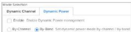
Dynamic Power can be configured in the following two modes:
- By-Band: Considers neighbor APs across all channels of same band for operating Auto-RF dynam transmit power.
This is the default option in the Dynamic Power configuration.
- By-Channel: Considers only operating channel neighbor APs (that also within the same AP group) for operating Auto-RF dynamic transmit power.
When Auto-RF Dynamic Power is enabled, by default, CBS runs in the background with a 50% ov threshold between APs. The default minimum transmit power is set to 8 dBm. The dynamic-power cannot reduce the transmit power below this level, even if there is overlap in AP signals. The Minimum
Neighbor Threshold parameter defines the minimum number of neighboring APs required to enable dynamic power selection.
With Auto-RF Dynamic Power enabled, the system manages transmit power while maintaining a minim level and considering AP overlap and neighbor requirements.

Radio Configuration
For Auto-RF feature to function correctly, the following configuration is recommended:
- Basic section
• Channel Scan section
Basic section
Configure the following parameters in the Radio > Basic section with the recommended values:
- Channel—Auto
• Transmit Power—Auto - Channel Width—20, 40, 80, or 160 MHz based on the deployment
• Candidates Channel—All.
If you want to restrict the APs to operate on specific channels, you must configure the required channels.

Channel Scan section
Configure the following parameters in the Radio > Channel Scan section with the recommended values:
- Select the Continuous Background Scan (CBS) option—Selected by default.
- Wait Time in minutes
• Rest Time, Dwell Split Time, and Dwell Rest Time in milliseconds - Select the Channel Switch Announcement check box to enable the AP to send notifications before any channel change.

Configuring the Wireless LAN
This chapter describes the following topics:
- Overview
- Configuring the WLAN parameters
- Link Aggregation Control Protocol (LACP)
• RADIUS attributes
• Enterprise PSK (ePSK)
Configuring ePSKs
ePSK registration for WPA3 clients - Creating a Personal Wi-Fi ePSK
• RADIUS-based ePSK
• Groupwise Transient Key (GTK) per VLAN
• Dynamic ARP Inspection
Overview
Enterprise Wi-Fi AP devices support up to 16 unique WLANs. Each of these WLANs can be config the customer requirement and type of wireless station.
Configuring the WLAN parameters
To configure WLAN parameters, complete the following steps:
-
Navigate to Configuration > Wi-Fi Profiles > WLANs page.
-
Click Add and select Enterprise Wi-Fi from the Type drop-down list.
Following are the configurable parameters under the WLAN profile:
- Basic
- Radius Server
-
Guest Access
-
Internal Access Point
External Hotspot
cnMaestro -
Usage Limits
- Scheduled Access
- Access
- Passport
Basic
Table 23 lists configurable fields that are displayed in the WLANs > Basic Settings section.
Table 23 Basic parameters
| Parameters | Description Range Default | ||
| WLAN > Basic Settings | |||
| Enable Enables a WLAN profile. Once enabled, a Beacon is broadcasted with the SSID and the corresponding parameters configured in WLAN profile. | casted in a | ||
| SSID Unique | network name that wireless stations scan and associate. - - | ||
| Mesh This parameter is required when a WDS connection is established with Enterprise Wi-Fi devices. This parameter supports following options:Base:A WLAN profile configured with a mesh-base will operate as a normal AP. Its radio will beacon on startup SSID can be seen by radios configured as mesh clients.Client:A WLAN profile configured with mesh-client will scan all available channels on startup, looking for a mesh-base to connect.Recovery:WLAN profile configured as mesh-recovery will broadcast a pre-configured SSID upon detection of mesh link failure after a successful connection. This needs to be exclusively configured on a mesh-base device. Mesh client will auto scan for mesh-recovery SSID upon failure of mesh link.Off:Mesh support disabled on WLAN profile. | the will scan all available channels on startup, looking for a mesh-base to connect.will broadcast a pre-configured SSID upon detection of mesh link failure after a successful connection. This needs to be exclusively configured on a mesh-base device. Mesh client will auto scan for mesh-recovery SSID upon failure of mesh link. | ||
| VLAN Segregates wireless station traffic from AP traffic in the network. Wireless stations obtain an IP address from the subnet configured in the VLAN field of the WLAN profile. | W4094 1 | ||
Security Determines key values that are encrypted based on the algorithm. Following security methods are supported:OpenThis method is preferred when Layer 2 authentication is built into the network. With this configured on an Enterprise Wi-Fi AP device, any wireless station will be able to connect.OSENThis method is extensively used when Passport 2.0 is enabled on Enterprise Wi-Fi AP devices. If Passport 2.0 is disabled, this security plays no role in wireless station association.OWE (Enhanced Open)This method ensures the communication between each pair of endpoints is protected from other endpoints.WPA2 Pre-Shared KeysThis mode is supported with AES and TKIP encryption. WPA-TKIP can be enabled from the CLI with the allow-tkip CLI option. Note6 GHz clients connect to the AP using the secure Simultaneous Authentication of Equals (SAE) method.WPA2 EnterpriseThis security type uses 802.1x authentication to associate wireless stations. This is a centralized system of authentication methods.WPA2/WPA3 Pre-shared KeysWPA3 comes with a transition mode where WPA2-only capable clients can connect to SSID. WPA2-only capable clients connect using the older PSK method while WPA3 capable clients connect using a more secure SAE method. Note6 GHz clients connect to the AP using the secure Simultaneous Authentication of Equals (SAE) method.WPA2 EnterpriseThis security type uses 802.1x authentication to associate wireless stations. This is a centralized system of authentication methods.WPA2/WPA3 Pre-shared KeysWPA3 comes with a transition mode where WPA2-only capable clients can connect to SSID. WPA2-only capable clients connect using the older PSK method while WPA3 capable clients connect using a more secure SAE method. | selectOptech | ||
WPA3 Pre-shared KeysWPA3 replaces the Pre-Shared Key (PSK) exchange with SAE of Equals, which is more secure and provides forward-secrecy as well as resistance to offline dictionary attack. NoteWhen you select WPA2/WPA3 Pre-shared Keys or WPA3 Pre-shared Keys, you can enable registration flow for WPA3 clients.To enable the registration flow, you must create an ePSK passphrase and follow the procedure for the clients to undergo the registration flow.For more information, see ePSK registration for WPA3 clients. NoteWhen you select WPA2/WPA3 Pre-shared Keys or WPA3 Pre-shared Keys, you can enable registration flow for WPA3 clients.To enable the registration flow, you must create an ePSK passphrase and follow the procedure for the clients to undergo the registration flow.For more information, see ePSK registration for WPA3 clients. | |||
| WPA3 EnterpriseWPA3 also introduces Enterprise AES CCMP encryption. This level of security provides consistent cryptography and eliminates the mixing and matching of security protocols that are defined in the 802.11 standards.WPA3 Enterprise CNSAWPA3 also introduces a 192-bit cryptographic security suite. This level of security provides consistent cryptography and eliminates the mixing and matching of security protocols that are defined in the 802.11 standards. This security suite is aligned with the recommendations from the Commercial National Security Algorithm (CNSA) Suite and is commonly used in high-security Wi-Fi networks in government, defense, Finance, and industrial verticals.User Pre-shared keysThe U-PSK (User-PSK) Authentication settings are only used in conjunction with XMS Cloud's EasyPass Onboarding Portals. The Cloud automatically configures this setting for an WLAN when you create an Onboarding portal and you assign that WLAN to the portal. Thus, you should not normally change this setting manually. Note that the User-settings are only available on the WLAN profile.SSID can be configured to be transmitted as per the deployment requirement. For a regular access profile, available to configure transmit mode of SSID:2.4 GHz5 GHz6 GHz | NoteWhen you select WPA2/WPA3 Pre-shared Keys or WPA3 Pre-shared Keys, you can enable registration flow for WPA3 clients.To enable the registration flow, you must create an ePSK passphrase and follow the procedure for the clients to undergo the registration flow.For more information, see ePSK registration for WPA3 clients.- all options are | ||
| Band Each | |||
| Client Isolation | Enable this feature when there is a need for restriction of wireless station-to-station communication across the network or on an AP.Note For client isolation to work correctly, it is recommended that clients obtain their IP addresses through DHCP.You must manually update the default gateway addresses in the IP configuration of clients that are using static IP addresses.If the gateway MAC address changes due to hardware replacement or any other reason, you must restart the AP for the AP to learn the new gateway MAC address and to make sure the client isolation functions correctly.The following options are available to configure based on requirement:DisableThis option when selected disables the client isolation feature. that is, any wireless station can communicate to other wireless stations.LocalThis options when selected enable the client isolation feature. This option prevents wireless station communications connected to the same AP.Network WideThis options when selected enable the client isolation feature. It prevents wireless stations communications connected to different AP deployed in the same For client isolation to work correctly, it is recommended that clients obtain their IP addresses through DHCP.You must manually update the default gateway addresses in the IP configuration of clients that are using static IP addresses.If the gateway MAC address changes due to hardware replacement or any other reason, you must restart the AP for the AP to learn the new gateway MAC address and to make sure the client isolation functions correctly.The following options are available to configure based on requirement:DisableThis option when selected disables the client isolation feature. that is, any wireless station can communicate to other wireless stations.LocalThis options when selected enable the client isolation feature. This option prevents wireless station communications connected to the same AP.Network WideThis options when selected enable the client isolation feature. It prevents wireless stations communications connected to different AP deployed in the same NoteNetwork-wide mode is not supported Redundancy Gateway protocol is used on deployment.In the Redundancy Gateway case, Network-wide static can be used to a list of Gateway MAC addresses. NoteNetwork-wide mode is not supported Redundancy Gateway protocol is used on deployment.In the Redundancy Gateway case, Network-wide static can be used to a list of Gateway MAC addresses. | onL2 network.whenonprovide | |
• Network Wide StaticThis option when configured enables client isolation feature across the network. Wireless stations can communicate only to statically added MAC list. Communication to rest other MAC addresses are blocked. NoteWhen Network Wide and Network Wide are selected, the user has the provision to add the whitelist MAC addresses to allow the communication. A maximum of 64 MAC addresses can be added. NoteWhen Network Wide and Network Wide are selected, the user has the provision to add the whitelist MAC addresses to allow the communication. A maximum of 64 MAC addresses can be added. | Static | ||
| cnMaestro Managed Roaming | Provision to enable centralized management of roaming wireless clients through cnMaestro. | -for | - |
| Hide SSID | This is the basic security mode of a Wi-Fi device. This disabler when enabled, will not broadcast SSID. | Disabler | |
| Session Timeout | This field applies to all wireless clients connected to When a wireless station connects, a session timer is Once session time expires, the wireless station must either re-authentication or re-association based on the the wireless station. By default, it is enabled. NoteFollowing priority takes precedence for the timeout: NoteFollowing priority takes precedence for the timeout: | 60e SSID.2880060430ed.undergo state ofsession | |
| Parameters | Description Range Default | |||
| a. Configured from the RADIUS serverb. Configured from the AP | ||||
| InactivityTimeout | Inactivity timer triggers whenever there is no communication between Enterprise Wi-Fi AP device and wireless station associated to Enterprise Wi-Fi AP device. Once the timer reaches the configured Inactivity timeout value, APs send a de-authentication to that wireless station. By default, it is enabled. | 60en28800inactivity | 1800 | |
| NoteFollowing priority takes precedence for the timeout:a. Configured from the RADIUS serverb. Configured from the AP | ||||
Figure 16 Basic parameters

Table 24 WLAN (Max clients) parameters
| Number of clients | 2.4 GHz 5 | GHz 6 GHz | Concurrent | |
| XV3-8 512 1024* NA | 1536 | |||
| XE5-8 512 1024* 10 | 24** 2560 | |||
| XV2-2 512 512 NA | 1024 | |||
| XV2-2T0 512 512 NA | 1024 | |||
| XV2-2T1 512 512 NA | 1024 | |||
| XE3-4 512 512 512 | 1536 | |||
| XE3-4TN | 512 512 512 | 1536 | ||
| XV2-21X | 128 128 NA | 256 | ||
| XV2-23T | 128 128 NA | 256 | ||
| XV2-22H | 128 128 NA | 256 | ||
| e410/e430 and e510 | 256 | 256 | NA 256 | |
| e600 and e700 | 512 512 | NA 512 | ||
| X7-35X | 256 | 256 | 256 | 768 |
* Two 5 GHz radios are available in Single Band Simultaneous (SBS) mode.
** Two 6 GHz radios are available in XE5-8 platform.
Maximum wireless client
At present, the WLAN profile provides an option to configure the maximum wireless clients association limit. This configuration limits the maximum number of clients per SSID per radio. For example, if a user configures the maximum wireless client as 10, on a device capable of 2.4 GHz and 5 GHz radios, the total number of clients that can be associated is 10 across each radio. This has been enhanced in Release 6.5 to set the maximum clients limit per SSID irrespective of the number of radios to which SSID has been mapped.
Maximum clients per device
Most customers commonly use more than a single SSID. They prefer to set the maximum number of wireless clients connection per device, that is, irrespective of the number of WLAN profiles and the number of radios, the maximum number of clients that can be associated is equivalent to the value configured for the parameter max-clients. This is a global configuration.
CLI configuration:
ap(config)# max-clients
0|<1-1536> '0' disables max client per device
Maximum clients per SSID
This option helps to limit the number of wireless clients connected to a WLAN profile (SSID) irresp the number of radios. This configuration is supported at the WLAN level. This can be enabled as
CLI configuration:
ap(config)# wireless wlan 1
ap(config-wlan-1)# enforce-max-clients-per-ssid
Maximum clients per SSID per radio
This is the default configuration of the device. This configuration limits the maximum number of client SSID per radio. For example, if a user configures the maximum wireless client as 20, on a device 2.4 GHz and 5 GHz radios, the total number of clients that can be associated is 20 across each configuration is supported at the WLAN level.
CLI configuration:
ap(config)# wireless wlan 1
ap(config-wlan-1)# max-associated-clients
<1-1536>
The default priority order can be:
- Per device (Global limit)
- Per SSID and (enforce at SSID level)
- Per SSID per radio basis (present default option)
To keep backward compatibility with the existing deployments, the default option can be Per SSID basis.
Opportunistic Wireless Encryption (OWE)
OWE is a Wi-Fi standard, which ensures that the communication between each pair of endpoints is protected from other endpoints. The OWE transition mode allows OWE-capable STAs to access the in OWE authentication mode. The OWE transition mode is implemented as follows:
You must create two WLANs on an AP.
For example,
- WLAN-1:
open authentication
owe-transition-ssid: Provides WLAN-2 owe security SSID
2. WLAN-2:
owe authentication
owe-transition-ssid: Provides WLAN-1 open security SSID
CLI configuration:
ap(config-wlan-1)# owe-transition-ssid
owe-transition-ssid : Configure the matching open/owe transition ssid

Note
The OWE transition mode SSIDs do not apply to 6 GHz radios.
Table 25 Advanced parameters
| Parameters | Description Range Default | |||||
| WLAN > Advanced | ||||||
| VLANPooling | This parameter is required when a user requires to distribute and receives across multiple subnets. Different modes of VLAN pooling is supported by Enterprise Wi-Fi AP devices, based on infrastructure available at the deployment site. Modes supported are as follows:DisabledThis feature is disabled for this WLAN.Radius BasedThe user is expected to configure WPA2 Enterprise mode to support. During the association phase, AP pool name from RADIUS transaction and based on distribution of wireless station across VLANs, AP selects appropriate VLAN and wireless station requests an IP address from the VLAN selected by Enterprise Wi-Fi AP device.StaticFor this mode to support, the user requires to configure VLAN Pool details available under Configure > Network > VLAN pool. During the association phase, AP obtains pool, and based on the present distribution of wireless station across VLANs, AP selects appropriate VLAN and wireless station requests an IPv4 address from the VLAN selected by the Enterprise Wi-Fi AP device. | Disabilitiesas follows:for this obtains the presentIP address | ||||
| Max Clients | This specifies the maximum number of wireless stations associated with a WLAN profile. This varies based on Wi-Fi AP device model number.Refer to Table 24 for | 1-512 can Save (ReferEnterprise Tenore details.24) | 256e | |||
| UAPSD When enabled, Enterprise Wi-Fi AP devices support WMM Power Disabled Save / UAPSD. This is required where applications such as VOIP Calls, Live Video streaming are in use. This feature helps to prioritize traffic. Below is the default traffic priority followed by Enterprise Wi-Fi AP device. | ||||||
| Priority | 802.1D Priority(-UP) | 802.1D Designation | Access Category | WMM Designation | ||
| lowesthighest | 1 | BK | AC_BK | Background | ||
| 2 | - | |||||
| 0 | BE | AC_BE | Best Effort | |||
| 3 | IE | |||||
| 4 | CL | AC_VI | Video | |||
| 5 | VI | |||||
| 6 | VO | AC_VO | Voice | |||
| 7 | NC | |||||
| QBSS When enabled, appends QBSS IE in Management frames. This - IEDisabled provides information on channel usage by AP, so that wireless stations can decide better AP for connectivity. Station count, Channel utilization, and Available admission capacity are the information available in this IE. | – IEDisabled smart Station station count, Channel utilization, and Available admission capacity are the information available in this IE. | |||||
| DTIM interval This parameter plays a key role when power save supported mobile stations are part of the infrastructure. This field when enabled controls the transmission of Broadcast and Multicast frames. | – IEDisabled when enabled controls the transmission of Broadcast and Multicast frames. | |||||
| Monitored Host | ||||||
| Host This feature is required where there is an interrupted backbone network. Enterprise Wi-Fi AP device monitors the reachability of hostname/IP configured in this parameter and modifies the state of WLAN. | – Disabled network. Enterprise Wi-Fi AP device monitors the reachability of hostname/IP configured in this parameter and modifies the state of WLAN. | |||||
| Interval The frequency of monitoring the network health based on status of the keep-alive mechanism w.r.t configured monitor host. | – Frequency of monitoring the network health based on status of the keep-alive mechanism w.r.t configured monitor host. | 300 sec | ||||
| Attempts The number of packets in the keep-alive mechanism to determine the status. | – Frequency of monitoring the keep-alive mechanism w.r.t configured monitor host. | 300 sec | ||||
| DNS Logging Host By enabling this feature, the Administrator can monitor websites accessed by wireless stations connected to WLAN profile. | – Frequency of monitoring the keep-alive mechanism w.r.t configured monitor host. | 300 sec | ||||
| Parameters | Description Range Default | ||
| Connection Logging Host | When enabled provides information of all IP connections by a wireless station that is associated with WLAN and logs connection data seamlessly onto an external syslog server. | accDisabled the | |
| Band Steering | This feature when enabled steers wireless stations to connected 5GHz. There are three modes supported by Enterprise devices. The mode can be selected based on either wireless station type. Below is the order of modes, which forces the wireless station to connect to the 5 GHz band.LowNormalAggressive | connDisabled Wi-Fi deployment or | |
| Proxy ARP | Provision to avoid ARP flood in a wireless network. When Enabled, AP responds to ARP requests for the wireless stations that AP. This is for IPv4 infrastructure. | connected to | |
| Proxy ND | When enabled, AP responds to IPv6 Neighbor Discovery (ND) requests for the wireless stations connected to that AP. | ||
| Unicast DHCP | Provision to transmit DHCP offer and ACK/NACK packets – enabled Unicast packets to wireless stations. | ||
| Insert DHCP Option 82 | When enabled, DHCP packets generated from wireless that are associated with APs are appended with Option 82 parameters. Option 82 provides a provision to append and Remote ID. Following parameters can be selected Circuit ID and Remote ID:HostnameAP MACBSSIDSSIDVLAN IDSITEIDCustomAll | stationDisabled Circuit ID in both |
| Parameters | Description Range Default | |||
 | NoteIn case DHCP Option 82 is configured at the device-,WLAN profile-, and L3 interface-levels, the following priority order is considered:1. Device-level configuration2. WLAN profile-level configuration3. L3 interface-level configuration | |||
| Tunnel Mode | This option is enabled when user traffic is tunneled to network either using L2TP or L2GRE. | to Disable | BMZ | |
| Fast-Roaming Protocol | One of the important aspects to support voice applications Disabled Wi-Fi network (apart from QoS) is how quickly a client can move its connection from one AP to another. This should be less than 150 ms to avoid any call drop. This is easily achievable when the WPA2-PSK security mechanism is in use. However, in enterprise environments, there is a need for more robust security (the one provided by WPA2-Enterprise). With WPA2-Enterprise, the client exchanges multiple frames with the AAA server, and hence depending on the location of the AAA server the roaming time will be above 700 ms.Select any one of the following:OKCThis roaming method is a Cambium Networks proprietary solution to share the client authentication information with other Cambium Networks APs on the same network by sending encrypted information on wire on SSID VLAN. This information sharing does not require cnMaestro so even in cases where AP is not connected to cloud, the roaming will be seamless.802.11r | when the WPA2- | ||
| Fast transition (FT) is an IEEE standard to permit connectivity aboard wireless devices in motion, with secure client transitions from one Basic Service Set (abbreviated BSS, and also known as a base station or more colloquially, an access point) to another, performed in a nearly seamless manner. The terms handoff and roaming are often used, although 802.11 transition is not a true handoff/roaming process in the cellular sense, where the process is coordinated by the base station and is generally uninterrupted. | continuous fast and | |||
| RRM (802.11k) | AP sends the SSID name of the neighbor APs (SSID - c-Disfected on multiple APs) to 802.11k clients.The following parameter must be enabled:Enable RRM | - | ||
| 802.11v Provision to enable 802.11v BSS Transition Management. - Disabled | ||||
| PMF(802.11w) | 802.11w also termed as Protected Management Frames Service, defines encryption for management frames. Unen encrypted to DoS management frames make wireless connection vulnerable attacks as well as they cannot protect important information exchanged using management frames from eavesdroppers | (PMF)Optional | ||
| SA QueryRetry Time | The legitimate 802.11w client must respond with a Secu#y-500 Association (SA) Query Response frame within a pre-defined amount of time (milliseconds) called the SA Query Retry time. | 100ms | ||
| Association ComebackTime | This value is included in the Association Response as an Association Comeback Time information element. AP will deny association for the configured interval. | 1-20 1 | Sec | |
Figure 17 Advanced parameters

Band steering also supports client load balancing based on the below CLI configuration:
ap(config)# wireless wlan 1
ap(config-wlan-1)# band-steer-load-balancing
client-counts : client counts for band steer to consider clients load balancing
client-percentage : Client percentage for band steer to consider clients load balancing
WLAN VLAN allowed list
This is an optional CLI to configure the allowed VLAN list upfront. It is needed in multiple VLAN such as Dynamic VLAN, ePSK-based VLAN, and RADIUS VLAN.
CLI configuration:
ap(config)# wireless wlan 1
ap(config-wlan-1)# vlans-allowed
{vlan_list} <e.g 1-10,15,100>
ap(config-wlan-1)# vlans-allowed 1-10
ICMPv6 Router advertisement (RA) unicast conversion
Convert ICMPv6 RA Multicast packets to Unicast for all stations. ICMPv6 RA unicast conversion is r multiple VLAN scenarios such as Dynamic VLAN, ePSK-based VLAN, and RADIUS-based VLANs.
This CLI configuration allows to configure the VLANs where ICMPv6 RA unicast conversion is neede
CLI configuration:
ap(config)# wireless wlan 1
ap(config-wlan-1)# ipv6-router-advertisement-unicast
vlans : Configure vlans where IPV6 Router Advertisement unicast conversion needed
ap(config-wlan-1)# ipv6-router-advertisement-unicast vlans
{vlan_list} <e.g 1-10,15,100>
ap(config-wlan-1)# ipv6-router-advertisement-unicast vlans 1-10
802.11k/v
802.11k
Radio Resource Measurement (RRM) defines and exposes radio and network information to facilitate management and maintenance of a wireless network. 802.11k is intended to improve the way traffic distributed within the network.
The client can request a neighbor report from the AP using the neighbor_report_req management m. The client may request neighbors with matching SSID or request for all neighbors in the vicinity. The AP
collects the neighbor information using proprietary methods and provides the list of neighbors to the in the neighbor_report_rsp message.
802.11v
802.11v is deployed on the APs to govern the wireless networking transmission methods. It allows us and APs to exchange information regarding the network topology, and RF environment. This facilitates wireless devices to be RF-aware for participating in network-assisted power savings and network-assisted roaming methods.
The client may send solicited BSS Transition Management messages to AP before making roaming decisions. The idea is to identify the best APs to roam. The AP, after receiving the message from expected to respond with the best APs in the vicinity to assist the client in roaming. The neighbor information is collected using proprietary methods.
RADIUS server
To configure a RADIUS server, complete the following steps:
- Navigate to Configuration > Wi-Fi Profiles WLAN tab, select Radius Server tab and provide the details as given in Table 26:
Table 26 RADIUS Server parameters
| Parameters Description Range Default | |||
| Authentication Server | Provision to configure RADIUS Authentication server such as Hostname/IPv4, Shared Secret, Port Number and Realm. A maximum of three RADIUS servers can be configured. NoteThe Realm parameter can be left blank, you would like to use this server only usernames where the network domain is included.For example, in@cambium.com or,/, the realms @cambium.com and/, and this server will be selected only if the has the appropriate realm. NoteThe Realm parameter can be left blank, you would like to use this server only usernames where the network domain is included.For example, in@cambium.com or,/, the realms @cambium.com and/, and this server will be selected only if the has the appropriate realm. | detDisabled and unless for certain username | |
| Accounting Server | Provision to configure Accounting server details such - aDisabled Hostname/IPv4, Shared Secret, Port Number. A maximum of three RADIUS servers can be configured. | - aDisabled | |
| Timeout This field indicates wait time period for a response from 1-50e 3 AAA server. | |||
| Attempts Parameter to configure many attempts that a device should be 1 send AAA request to server if no response is received within the configured timeout period. | |||
| Accounting Mode | This field is enabled based on customer requirements. Disabled accounting packet is transmitted based on the mode selected.Start-StopAccounting packets are transmitted by AP to the AAA server when a wireless station is connected and then disconnects.Start-Interim-StopAccounting packets are transmitted by AP to the AAA server when a wireless station connects and then at regular intervals of configured Interim Update Interval and then when it disconnects.NoneThe accounting mode will be disabled. | ||
| Accounting Packet | When enabled, Accounting-On is sent for every client Disabled connected. | ||
| Sync Accounting Records | Provision to configure accounting records to be synced across neighboring APs. | ||
| Server Pool Mode | Users can configure multiple Authorization and Accounting Failover servers. Based on a number of wireless stations, the user can choose Failover mode.Load Balance—AP communicates with multiple servers and ensures that authorization and accounting are equally shared across configured servers.Failover—AP selects the RADIUS server which is up and running based on the order of configuration. | ||
| NAS-Identifier | This is a configurable parameter and is appended in the hostname/RADIUS request packet. | System Name | |
| Dynamic Authorization | This option is required, where there is CoA request disabled AAA/RADIUS server. | Disabled | |
| Dynamic VLAN | When enabled, AP honors the VLAN information provided the RADIUS transaction. Wireless station requests IP from the same VLAN learned through RADIUS. | address | |
| Called Station ID | The following information can be communicated to RADIUS server:AP-MACAP-MAC: SITE-NAMEAP-MAC: SSIDAP-MAC: SSID-SITE-NAMEAP-NAMEAP-NAME: SITE-NAMEAP-NAME: SSIDSITE-NAMESSIDCUSTOM | the AP-MAC: SSID | |
Figure 18 The RADIUS Server parameters
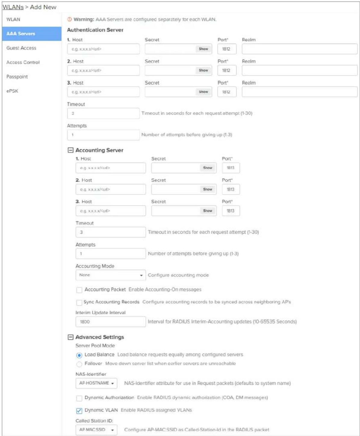
Proxy Through Controller
cnMaestro On-Premises can act as a proxy server for a AAA request coming from Enterprise Wi-Fi Points. In this scenario, cnMaestro acts as Network Access Server (NAS) for the AAA server.
The AP sends AAA packets to cnMaestro On-Premises, and cnMaestro forwards them to the AAA. When the Proxy Through Controller feature is enabled, CoA is supported other than AAA requests.
CLI configuration:
ap(config-wlan-1)# radius-server through-controller
Note: Applicable only with On-Premises controller
For activating Proxy Through Controller feature in cnMaestro On-Premises:
- Go to Administration > Settings.
- Enable RADIUS Proxy checkbox as shown in below figure.
Figure 19 RADIUS proxy
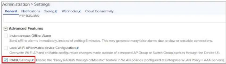
EAP-FAST support
EAP-FAST authentication occurs in two phases. In the first phase, EAP-FAST employs the TLS hands provide an authenticated key exchange and to establish a protected tunnel. Once the tunnel is est the second phase begins with the peer and server engaging in further conversations to establish the required authentication and authorization policies.
Guest Access
Internal Access Point
Below table lists configurable fields that are displayed in the WLANs > Guest Access > Internal Access Point page.
Table 27 Internal Access Point parameters
| Parameters Description Range Default | |||
| WLAN > Guest Access > Internal Access Point | |||
| Enable Enables | the Guest Access feature. - Disabled | ||
| Access Policy | There are four types of access types provided user:1. ClickthroughThis mode allows the users to get access data without any authentication mechanism. User can access the internet as soon as he is connected and accepts Terms and Conditions2. RADIUSThis mode when selected, the user has to provide a username and password, which is then redirected to the RADIUS server authentication. If successful, the user is provided with data access.3. Local Guest AccountUsers must configure username and password on the device, which has to be provided on the redirection page for successful authentication and data access. | - Clickthrough to for | |
| Redirect Mode | This option helps the user to configure the HTTPS mode of redirection URL.1. HTTPAP sends an HTTP POSTURL to the associated client, in the http://format.2. HTTPSAP sends HTTPS POSTURL to the success associated client, in the https://format. | HTTPTTO | |
| Redirect Hostname | Users can configure a friendly hostname, which - is added to the DNS server and is resolvable to Enterprise Wi-Fi AP IP address. This parameter once configured will be replaced with an IP address in the redirection URL provided to wireless stations. | - | |
| Title Users can | configure a Title to the splash page.Configured text in this parameter will be displayed in the redirection page. This text is usually Bold. | Up to 255 characters | Welcome To Cambium Powered Hotspot |
| Contents Users | can configure the contents of the Splash page using this field. Displays the text configured under charactersTitle section of the redirection page. | Up to 255 characters | Enter username and password to get Web Access |
| Terms Splash | page displays the text configured when the user accepts the Terms and Agreement. | up to 255 characters | - |
| Logo Displays | the logo image updated in URL http (s)://logo.png. Either PNG or JPEG format of the logo is supported. | - | - |
| Background Image | Displays the background image updated in URL - http (s)://backgroundimage.png. Either PNG or JPEG format of the logo is supported. | - | - |
| Success Action | Provision to configure redirection URL after successful login to captive portal services. Users can configure three modes of redirection URL:1. Internal Logout PageAfter successful login, the wireless client is redirected to the logout page hosted on AP.2. Redirect user to External URLHere users will be redirected to the URL which is configured on the device in Redirection URL configurable parameter.3. Redirect user to Original URLHere users will be redirected to the URL that is accessed by the user before successful captive portal authentication. | Logout page | |
| Redirect user External URL | Provision to configure re-direction URL after successful login and additional information of AP and wireless station information can be appended in the URLPREFIX Query Strings in Redirect URLThis option is selected by default. The following information is appended in the redirection URL:SSIDAP MACNAS IDAP IPClient MACRedirection URLUsers can provide either HTTP or HTTPS URL | - | |
| Redirection user to Original URL | Users will be redirected to the URL that is accessed by the user before successful captive portal authentication.There are additional parameter Prefix Query Strings in Redirection URL that is enabled by default and details given below:Prefix Query Strings in Redirect URLThis option is selected by default. The following information is appended in the redirection URL:SSIDAP MACNAS ID | - | |
| Success message | Provision to configure the text to display upon - successful Guest Access authentication. This is applicable only when Success Action mode is Logout Page. | Internal | - |
| Redirect | If enabled, only HTTP URLs will be redirected, enabled the Guest Access login page.If disabled, both HTTP and HTTPS URLs will be redirected to the Guest Access login page. | - | |
| Redirect User Page | IPv4 address configured in this field is used URL for Guest Access sessions. | as 1log but | |
| Proxy Redirection Port | The proxy port can be configured with which server is enabled. This allows URLs accessedport to be redirected to the login page. | 1proxy65535 with proxy | - |
| Session Timeout | This is the duration of time, the client will access the internet if quota persists, after which sends de-authentication. The wireless station has to undergo Guest Access authentication after session timeout. NoteFollowing priority takes precedence for the session timeout:a. Configured from the RADIUS serverb. Configured from the AP NoteFollowing priority takes precedence for the session timeout:a. Configured from the RADIUS serverb. Configured from the AP | 60- allowed2592000 | 28800 |
| Inactivity Timeout | Provision to configure timeout period to disconnect wireless stations that are associated but have traffic. AP starts a timer when there is no data received from a wireless station and disconnects when reaches zero. NoteFollowing priority takes precedence for the inactivity timeout:a. Configured from the RADIUS serverb. Configured from the AP NoteFollowing priority takes precedence for the inactivity timeout:a. Configured from the RADIUS serverb. Configured from the AP | 60-2592000data received the timer | 1800 |
| MAC Authentication Fallback | It is a mechanism in which wireless stations redirected to the Guest Access login page after any supported type of MAC address authentication | will Disabled fails. | |
| Whitelist Provision | on to configure either IPv4 or URLs to bypass-traffic, therefore user can access those IPs or without Guest Access authentication. | URLs | - |
Figure 20 The Internal Access Point parameters
![VMware > Active New Health Sub-Servers User Active User Active: Main User Active: User Access Settings • Default Style: Sub-Form Page with some below text and contains in print on file networks • HTTPID: Text page with content and content1, default code with HTTPID or her • LDAP: Default code in a target page for authentication log at 2.047 version • Local Web Account: Default code to be logged by the authentication by the local user account IP Service Protocol • HTTP ID: User accessed HTTP protection or AP server access server • HTTP ID: User accessed HTTP access to IP plant access server Default Properties Default Resources to the upload page log at 2.05 information Type [Text] in upload page (print 2.05 programming) Contents: Enter components of the upload page (up to 2.05 information) Forms: Forms and contents displayed in the server pages (up to 2.05 information) Logos: My Internet Commanding Logins for displayed in the upload page Background Image My Internet Commanding/Message: Background Image to be displayed on the upload page Sources: download Internet Linked Pages Recommended User to Download URL Recommended User to Download URL Sources Message Advanced Settings Desktop • HTTPID only: Update subscription via HTTP packets only Description Page 1641 Description Port Print number (in ISO/ISO) Session Times 2890 Session time in seconds (30 to 35/4/4/5) Subscription Time 4000 Subscription time in seconds (30 to 35/4/4/5) MAC Authentication Pathback: Use Google access only as Network for clients setting MAC submission Download Messages Configure the system which is extended for user access Pre-Login Allowed Domains IP Address / Domain Name Add New Delete and IP address is an Extension Server Definition Capture Portal Skipover User Agent Add New Delete User Agent Setting: HTTP Code: HTTP Reply: Delete No User Agent needs available](/content/2026/05/908365/images/89bff06807b02e33c74f2d6340d1a507b0347c7f2feab6586571f963d09e0d73.jpg)
External Hotspot
Below table lists the configurable fields that are displayed in the WLANs > Guest Access > External Hotspot tab.
Table 28 External Hotspot parameters
| Parameters Description Range Default | ||
| WLAN > Guest Access > External Hotspot | ||
| Access Policy There are four types of access types provided end user:1. ClickthroughThis mode allows users to get access data without any authentication mechanism. The user can access the internet as soon as he is connected accepts the Terms and Conditions. | for Clickthroughand | |
| Parameters Description | Range Default | ||
| 2. RADIUSThe user has to provide a username and password, which is then redirected to a RADIUS server for authentication. If successful, the user is provided with data access.3. Local Guest AccountThe user has to configure username and password on the device, which has to be provided on the redirection page for successful authentication and data access. | |||
| Redirect Mode Provision to configure the HTTP or HTTPS mode http redirection URL.1. HTTPAP sends an HTTP POSTURL to the associated client, in the http://format.2. HTTPSAP sends an HTTPS POSTURL to the associated client, in the http://format. | |||
| Redirect Hostname | Users can configure a friendly hostname, which is added to the DNS server and is resolvable to Enterprise Wi-Fi AP IP address. This parameter once configured will be replaced with an IP address in the redirection URL provided to wireless stations. | - | |
| External Page URL | Users can configure a landing/login page that is posted to wireless stations that are not Guest Access authenticated. | - | |
| External Portal Post Through cnMaestro | This is required when HTTPS is only supported disabled external guest access portal. This option when enabled minimizes certification. The certificate is required to install only in cnMaestro On-Premises. | ||
| External Portal Type | Enterprise Wi-Fi AP products are supported by standard mode configuration.• Standard | ||
| This mode is selected, for all third-party vendors whose Guest Access services are certified and integrated with Enterprise Wi-Fi AP products. | |||
| Success Action Provision to configure redirection URL after successful login to captive portal services. User can configure three modes of redirection URL:1. Internal Logout PageAfter successful login, the wireless client is redirected to the logout page hosted on AP.2. Redirect user to External URLHere users will be redirected to the URL which is configured on a device in Redirection URL configurable parameter.3. Redirect user to Original URLHere users will be redirected to a URL that is accessed by the user before successful portal authentication. | - Internal User can | - | Logout Page |
| Redirect user to External URL | Provision to configure re-direction URL after successful login and additional information of wireless station information can be appended URL.- Prefix Query Strings in Redirect URLThis option is selected by default. The following information is appended in the redirection URL:○ SSID○ AP MAC○ NAS ID○ AP IP○ Client MAC○ RedirectionURL○ Users can provide either HTTP or HTTPS URLs. | -AP and in the | - |
| Redirection user to Original URL | Users will be redirected to the URL that is- accessed by the user before successful captive portal authentication. There are additional parameter Prefix Query Strings in Redirection URL that is enabled by default and details given below:Prefix Query Strings in Redirect URLThis option is selected by default. The following information is appended in the redirection URL:SSIDAP MACNAS IDAP IPClient MAC | - | |
| Success message | Provision to configure the text to display upon successful Guest Access authentication. This is applicable only when Success Action mode is Internal Logout Page. | - | |
| Redirection URLQuery String | The following information is appended in the- Disabled redirection URL, if Prefix Query Strings in URL is enabled.Client IPRSSIAP Location | Redirect | |
| Redirect • | If enabled, only HTTP URLs will be redirected Enable the Guest Access login page.If disabled, both HTTP and HTTPS URLs will be redirected to the Guest Access login page. | ||
| Redirect User Page | The IP address configured in this field is - used as logout/disconnect/redirect to captive portal URL for Guest Access sessions. The IP address configured should not be reachable to the internet. | - | |
| Proxy Redirection Port | The proxy port can be configured with which -pr6535 server is enabled. This allows URLs accessed with proxy port to be redirected to the login page. | - | |
| Session Timeout | This is the duration of time, the client will to access the internet if quota persists, after sends de-authentication. The wireless station undergo Guest Access authentication after session timeout. NoteFollowing priority takes precedence for the session timeout:a. Configured from the RADIUSb. Configured from the AP NoteFollowing priority takes precedence for the session timeout:a. Configured from the RADIUSb. Configured from the AP | 60 - allowed2592000 APhas to server | 28800 |
| Inactivity Timeout | Provision to configure timeout period to disconnect wireless stations that are associated but have 2592000 data traffic. AP starts a timer when there is no received from a wireless station and disconnects when the timer reaches zero. NoteFollowing priority takes precedence for the inactivity timeout:a. Configured from the RADIUSb. Configured from the AP NoteFollowing priority takes precedence for the inactivity timeout:a. Configured from the RADIUSb. Configured from the AP | 60ect2592000 data data server | 1800 |
| MAC Authentication Fallback | It is a mechanism in which wireless stations- w disabled redirected to the Guest Access login page supported type of MAC address authentication failures. NoteThis feature works only when Guest Access is configured with RADIUS authentication under WLANs > Guest Access > Access Policy > RADIUS. NoteThis feature works only when Guest Access is configured with RADIUS authentication under WLANs > Guest Access > Access Policy > RADIUS. | Disabled after any | |
| Extend Interface | Provision to support the Guest Access on the Ethernet interface. | - Disabled | |
Figure 21 External Hotspot parameters

cnMaestro
The following table lists configurable fields that are displayed in the WLANs > Guest Access > cnMaestro page:
Table 29 The cnMaestro parameters
| Parameters | Description Range Default | |||
| WLAN > Guest Access > cnMaestro | ||||
| Guest Portal Name | Provision to configure the name of the Guest Access which is hosted on CnMaestro. | -profile | - | |
| Redirect • | If enabled, only HTTP URLs will be redirected to Access login page.If disabled, both HTTP and HTTPS URLs will be Guest Access login page. | - then ignored redirected | to | |
| Redirect User | The IP address configured in this field is used as | a logout | URL for | |
| Page Guest | Access sessions. The IP address configured should be not reachable to the internet. | |||
| Proxy Redirection Port | The proxy port can be configured with which proxy enabled. This allows URLs accessed with proxy port redirected to the login page. | server65535 to be | - | |
| Inactivity Timeout | Provision to configure timeout period to disconnect wireless stations that are associated but have no data traffic. 2592000ts timer when there is no data received from a wireless station disconnects when the timer reaches zero. | NoteFollowing priority takes precedence for the inactivity timeout:a. Configured from the RADIUS serverb. Configured from the AP | 1800a and | |
| Whitelist Provision to configure either IPs or URLs to bypass traffic, such that user can access those IPs or URLs without Guest Access authentication. | - | |||
Figure 22 cnMaestro parameters
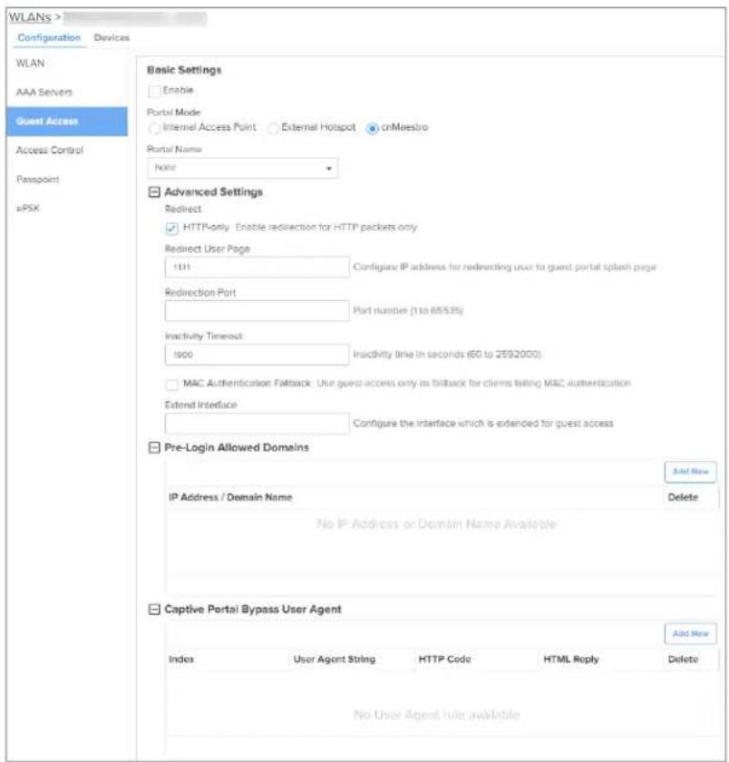
Usage Limits
Below table lists configurable fields that are displayed in the WLANs > Access Control > Usage Limits section.
Table 30 Usage Limits parameters
| Parameters | Description Range Default | ||
| Rate Limit Client | Provision to limit throughput per client. Default allowed throughput per client is unlimited, that is, maximum allowed by[Unlimited] 802.11 protocols. The traffic from/to each client on an rate-limited in either direction by configuring the client available in usage limits inside the WLAN Configuration. This is useful in deployments like public hotspots where the backhaul is limited and the network administrator would like to ensure that one client does not monopolize all available bandwidth. | - 0 | |
| Rate Limit WLAN | Provision to limit throughout across WLAN irrespective number of associated wireless stations to WLAN. All upstream/downstream traffic on an SSID (aggregated across all wireless clients) can be rate-limited in either direction by configuring usage limits inside the WLAN configuration the GUI. This is useful in cases where multiple SSIDs are being used and say one is for corporate use, and another. The network administrator can ensure that the guest is always throttled, so it will not affect the corporate | of a cross all by section of VLAN traffic WLAN. | [Unlimited] of being guests. |
Figure 23 The Usage Limits parameters

Scheduled Access
Below table lists configurable fields that are displayed in the WLANs > Access Control > Scheduled Access section.
Table 31 The Scheduled Access parameters
| Parameters | Description Range Default | |||
| Scheduled Access | Provision to configure the availability of Wi-Fi services selected time duration. Enterprise Wi-Fi AP has the cap-figuring the availability of Wi-Fi services on all days day (s) of a week. The time format is in Hours. | for 0:00ability - of 28r59a Hrs. | Disabled specific | |
 | Note | |||
| Parameters | Description | Range Default | ||
| From release version 6.3 onwards, users are to configure up to a maximum of 12 scheduled rules per day on a particular WLAN instead per day. | allowed uled access of one rule | |||
Figure 24 The Scheduled Access parameters

CLI Configuration:
ap(config)# wireless wlan 1
ap(config-wlan-1)# scheduled-access
all : all
friday : friday
monday : monday
saturday : saturday
sunday : sunday
thursday : thursday
tuesday : tuesday
wednesday : wednesday
weekday : weekday
weekend : weekend
ap(config-wlan-1)# scheduled-access all
Time period in HH:MM-HH:MM,HH:MM-HH:MM format
Access
Below table lists configurable fields that are displayed in the WLANs > Access Control tab.
Table 32 The Access parameters
| Parameters Description Range Default | |||
| DNS-ACL | |||
| Precedence Provision to configure index of ACL rule. Packets are validated and processed based on the Precedence value configured. | 1 | ||
| Action Provision to configure whether to allow or deny traffic. - Deny | |||
| Domain Provision to configure domain names and rules are applied on Action configured. | based | - | |
| MAC Authentication | |||
| MAC Authentication Policy | Enterprise Wi-Fi AP supports multiple methods of MAC authentication. Following are the details of each mode1. PermitWireless station MAC addresses listed will be allowed to associate to AP.2. DenyWhen the user configures a MAC address, those wireless stations shall be denied to associate and the non-listed MAC address will be allowed.3. RADIUSFor every wireless authentication, AP sends a RADIUS request and if RADIUS acceptance is received, then the wireless station is allowed to associate.In case authentication fails, you can enable AP to assign the default WLAN VLAN to the clients. For this, you must configure the failed-allow-traffic CLI command. For more information, see Fallback to WLAN VLAN when RADIUS-based MAC authentication fails.4. cnMaestroThis option is preferable when the administrator prefers a centralized MAC authentication policy. For every wireless authentication, AP a sends query to cnMaestro if it is allowed or disallowed to connect. Based on the configuration, wireless stations are either allowed or denied. | - Deny | |
To configure DNS ACL:
- Select Precedence from the drop-down list.
- Select type of action from Action drop-down list.
- Enter a domain name in the Domain textbox.
- Click Save.
To configure MAC Authentication:
- Select MAC Authentication Policy from the drop-down list.
- Enter MAC in the textbox.
- Enter Description in the textbox.
- Click Save.
Figure 25 The Access parameters
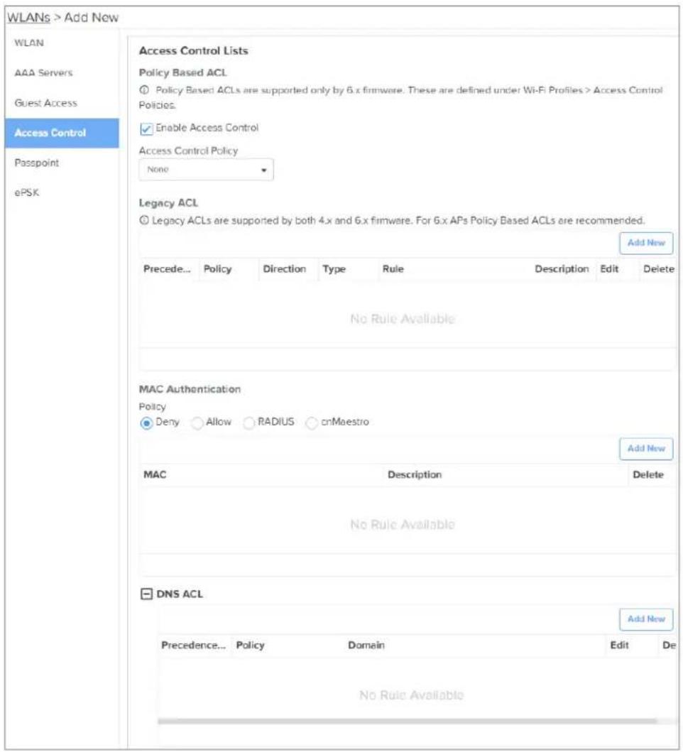
Sample DNS-ACL configuration
If any user wants to block Facebook or Youtube traffic and allow the rest of the traffic, the cor shown in below figure:
Figure 26 Sample DNS-ACL configuration

Fallback to WLAN VLAN when RADIUS-based MAC authentication fails
When a client passes RADIUS-based MAC authentication, the RADIUS server assigns the configured \ However, if clients fail the authentication, you can configure the AP to assign the default WLAN \ enables the AP to allow limited access to clients, or redirects the clients to a captive portal page available in the RADIUS MAC authentication list. Once the captive portal authentication is successful, RADIUS server dynamically disconnects the client and assigns the RADIUS VLAN when the clients tr connect later.
To assign the default WLAN VLAN to such clients, you must include the mac-authentication radius failed-allow-traffic CLI command in the AP Groups > User Overrides section in cnMaestro.
This feature is only available for RADIUS-based MAC authentication. The use case for this feature i provide limited access to clients not included in the approved RADIUS MAC authentication list, such granting access to a walled garden, the internet, or redirecting the clients to go through the capti authentication.
Figure 27 failed-allow-traffic in RADIUS-based MAC authentication

Passpoint
Below table lists configurable fields that are displayed in the WLANs > Passpoint tab.
Table 33 Passpoint parameters
| Parameters | Description Range Default | ||
| Passpoint parameters | |||
| Enable Passpoint (Release 2) enables secure hotspot network access, online sign-up, and policy provisioning. | - Disabled | ||
| DGAF Downstream Group Addressed Forwarding when enabled the WLAN does not transmit any multicast and broadcast packets. | - Disabled | ||
| ANQP Domain ID | ANQP domain identifier is included when the HS 2.0 element is in Beacon and Probe Response frames. | Indication 65535 | 0 |
| Comeback Delay | Comeback Delay in milliseconds. 100- | 2000 | 0 |
| Access Network Type | The configured Access Network Type is advertised to Following are the different network types supported:PrivateChargeable PublicEmergency ServicesFree PublicPersonal DevicePrivate with GuestTestWildcard | STAS Private | |
| ASRA This | indicates that the network requires a further step for access. - | Disabled | |
| Internet The | network provides connectivity to the Internet if not specified. - | Disabled | |
| HESSID Configures the desired specific HESSID network identifier or wildcard network identifier. | the | - | |
| Venue Info | Configure venue group and venue type. - - | ||
| Roaming Consortium | The roaming consortium and/or SSP whose security credentials can be used to authenticate with the AP. | ||
| ANQP Elements | Select any one of the following:3GPP Cellular Network InformationConnection CapabilityDomain Name ListIconsIP Address Type informationNAI Realm ListNetwork Authentication TypeOperating Class IndicationOperator Friendly NamesOSU Provider ListVenue Name InformationWAN Metrics | - | - |
Figure 28 Passpoint parameters

RADIUS attributes
The table below shows the RADIUS attributes describes their interpretation.
Table 34 Radius attributes parameters
| Type Attribute | Name | Attribute Number | Purpose |
| Standard Acct-Interim- 85 Spe | cifies theInterval updates | interval between accounting interim | |
| Standard Acct-Session-Id 44 Session identification (RFC 5176) | |||
| Standard Calling-Station-Id | 31 Session identification (RFC 5176) | ||
| Standard Class | 25 Accounting classification | ||
| Standard Event-Timestamp | 55 Replay protection (RFC 5176) | ||
| Standard Filter-ID 11 • | Assign station to a user group• Re-assign station to a different user group 5176) | ||
| Standard Framed-IP-Address | 8 Session identification (RFC 5176) | ||
| Standard Idle-Timeout 28 Specifies the amount of time a station may remain idle before its session is terminated | |||
| Standard NAS-IP-Address | 4 NAS identification (RFC 5176) | ||
| Standard NAS-Identifier 32 | NAS identification (RFC 5176) | ||
| Standard Session-Timeout | 27 Specifies the interval at which session is terminated | ||
| Standard Termination-Action | 29 Specifies the action to take when the session is terminated | ||
| Standard Tunnel-Type 64 Dynamic VLAN assignment (1 of 3 required), should be set to VLAN (Integer = 13) | |||
| Standard Tunnel-Medium-Type | 65 Dynamic VLAN assignment (2 of 3 required), should set to 802 (Integer = 6) | ||
| Standard Tunnel-Private-Group-ID | 81 Dynamic VLAN assignment (3 of 3 required), should set to the VLAN ID or name | ||
| Standard User-Name 1 | • | Station username update• Session identification (RFC 5176) | |
| Microsoft Vendor-Specific | MS-MPPE-Send-Key | 16 | Session key distribution |
| Microsoft Vendor-Specific | MS-MPPE-Recv-Key | 17 | Session key distribution |
(RFC
| Type Attribute | Name | Attribute Number | Purpose |
| Cambium Vendor-Specific | Cambium-Vlan-Pool-Id | 157 Radius | based VLAN pool |
| Nas Port ID | NAS-Port-Id 87 | NAS identification (RFC 5176) | |
Enterprise PSK (ePSK)
By using the ePSK feature, users can configure and support individual PSKs for different clients. The can be configured under a given WLAN configuration in cnMaestro UI. For on devices, only CLI is available.
This feature also supports individual VLAN assignments for a given key which helps to put client different VLANs for limiting broadcast traffic.

Note:
• Maximum key limit for cnMaestro Essentials: 300 per account
• Maximum key limit for cnMaestro X: 2000 per WLAN and 50000 per account
Configuring ePSKs
To create an ePSK, complete the following steps:
- Navigate to Configuration > Wi-Fi Profiles.
- Select WLAN tab and click Add.
- Select Enterprise Wi-Fi from the Type drop-down list and enter details in the Basic Information section.
- In the Basic Settings section, ensure the WPA2 Pre-Shared Keys option is selected in the Security drop-down list.
- Click Save.
- Click the ePSK tab and select the Local option in the Mode field.
-
Select the type of Passphrase Strength as one of the following options:
-
Easy—Supports a maximum of eight alphanumeric characters
• Strong—Supports a maximum of 16 alphanumeric and special characters
• Number—Supports a maximum of eight integers -
Click Add New.
The Add ePSK window is displayed.
- Select Mode type as one of the following options and configure the corresponding parameters:
- Single mode—Only one entry is created in this mode
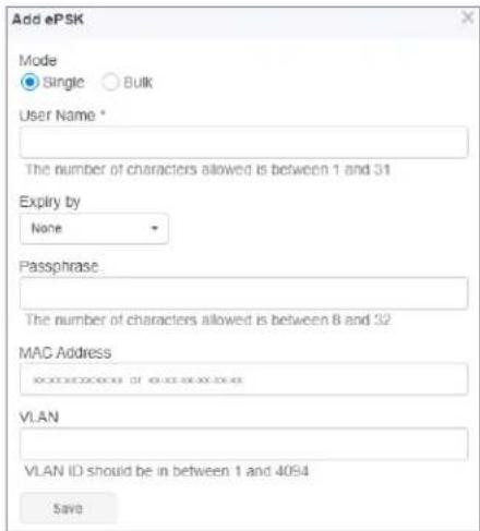

Note:
The Passphrase field is optional and is automatically generated based on the selected Passphrase Strength.
- Bulk mode—Multiple entries are created in this mode depending on the count configured


- To automatically expire ePSK details after a specific duration. The following options are available

Note:
This feature is available from cnMaestro 4.1.0 and later versions only.
- None—ePSK details never expire. Select None to never expire the ePSK credentials.
- Date and Time— ePSK expires after the specified date and time (in dd/mm/yyyy hh:mm AM format)
Supported minimum time is 12 A.M. on the next day and the maximum is five years.
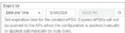
- Duration—ePSK expires after the specified (in hours, days, months, or years) in the Expiry by drop-down.
Supported minimum duration is one hour and the maximum is five years. No decimal values supported, for example, 1.5 hours.
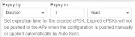

Note:
- The configured expiry time appears in the Expiration Date column on the WLANs >
page. - The Status column on the WLANs >
page displays the status of the ePSK details—Active, Expired, or None. None is displayed only when older ePSK keys are imported to cnMaestro. - Expired ePSK details are deleted from the AP only when the next configuration functionality is initiated or when there is a configuration change in the AP.
ePSK registration for WPA3 clients
For the ePSK feature, when you configure WPA3-WPA2 (mixed mode)-PSK or WPA3-PSK as the WLAN security, the clients connection in the WPA3 mode must go through an additional registration phase. different from the flow when you configure WPA2-PSK as the WLAN security, where users can authe by using only a passphrase.
When clients use WPA3-PSK security, Simultaneous Authentication of Equals (SAE) is the authentication mechanism where an extra authentication is added, which is more secure than WPA2. For WPA2-PSK clients, the passphrase is matched against a database to identify the user. However, this is not possible for WPA3-PSK clients because of the extra authentication in WPA3-SAE. When WPA2-PSK security is used by Pairwise Master Key (PMK) is the same for every connection made by the client. This is due to weaknesses in WPA2-PSK, which make it easier to validate the passphrase. In contrast, when WPA3-PSK security is used, a new PMK is generated each time a client joins the network. Therefore, registration help us to know the passphrase upfront when a client tries to connect. This mandates the users themselves with the ePSK passphrase to bind the client MAC with the passphrase to successfully do the Wi-Fi network.
For WPA3 clients to connect to the network using ePSK flow:
- First connect to the WLAN with the WLAN passphrase.
A simple password is recommended to be configured, for example, signmeup, or any other appropriate passphrase.
- Register themselves with the WPA3-ePSK unique passphrase.
After the MAC binding is complete, users can use the WPA3-ePSK unique passphrase for subse WLAN connections.
This section describes the following topics:
• ePSK with WPA3 feature recommendations
- Scenarios while registering clients
- Enabling ePSK registration flow using the AP CLI
- Configuring ePSK registration for WPA3 clients
- Registration flow screenshots
• Recommended best practices
ePSK with WPA3 feature recommendations
The following are the recommendations for this feature:
- This feature is supported only on cnMaestro Cloud 5.1.0 onwards.
• Supported AP firmware version is 6.6.1 or 7.0 and above.
• Security mode must be configured to either WPA2/WPA3 Pre-shared Keys or WPA3 Pre-shared Keys. - APs must be managed from cnMaestro Cloud for client registration.
• The WLAN VLAN must be able to provide DHCP to clients and must have internet connectivity
• This feature is not supported on Enterprise Wi-Fi 5 APs and Xirrus APs.
Scenarios while registering clients
When a client connects to the WLAN, the following scenarios are possible:
- When a client connects for the first time using WPA2 security and ePSK passphrase (either on or 5 GHz radios), the AP performs an ePSK lookup. The following are the outcome:
° If a match is found, the MAC binding is created with the respective ePSK key.
AP shares this MAC binding information with the other APs in the network.
° If a match is not found, the connection fails.
- If the WPA2 client is connected using the WLAN passphrase, client registration steps are performed by bind the passphrase to the client.
-
When a client connects for the first time using WPA3 security, the following two possibilities m
-
If MAC binding is not available for the client on the AP, the following procedure must be for successful registration of clients:
a. User must authenticate using the configured WLAN passphrase, for example, signmeup.
If the user tries to sign in with some other password other than the configured WLAN (signmeup), the connection fails.
b. If the connection with the configured password (signmeup) is successful, the AP redirects the client to the registration page.
This is the only traffic allowed for the client with this WLAN passphrase.
c. User must now enter the configured ePSK passphrase and register.
The AP redirects the client to the registration page with instructions.
d. Users must select the checkbox after reading the instructions (provided for different clients such as Android, Windows, and iOS), and then disconnect from the network.
e. User must forget the WLAN/SSID and reconfigure using the ePSK passphrase.
User then reconnects with ePSK passphrase and gets authenticated.
For a more detailed information, see Registration flow screenshots.
- When MAC binding is available for the client on the AP, users can authenticate the client passphrase present in the MAC binding, that is the ePSK passphrase.
Figure 29 Client registration flow for WPA3 clients

flowchart
graph TD
    A["Association Request"] --> B{Known MAC?}
    B -->|Yes| C["Complete Auth using ePSK for the MAC"]
    B -->|No| D{WPA2 or WPA3?}
    D -->|WPA2| E["Use ePSK WPA2 Lookup process to Complete Auth"]
    D -->|WPA3| F["Attempt to authenticate client with well known PSK"]
    F --> G{Success?}
    G -->|Yes| H["Record Success. Done"]
    G -->|No| I["Record Failure. Done"]
    H --> J["Inform client to reconnect using ePSK on the same SSID. Disconnect Client."]
    I --> K{Well known Key?}
    K -->|No| L["If failure exceeds threshold, check if device is still using the well known key by attempting to handshake with the well known key. (For WPA2, try ePSK key and well known key in one attempt)"]
    K -->|Yes| M["Send client to a "MAC Binding" Captive Portal to login via ePSK"]
    M --> N["Record Success. Done"]
    N --> O["Bind MAC address to ePSK and update common DB"]
    O --> P["Record Success. Done"]
Enabling ePSK registration flow using the AP CLI
To enable ePSK registration for WPA3 clients in the AP CLI, execute the following commands:
ap(config)# wireless wlan 1
ap(config-wlan-1)# epsk-registration-flow
Configuring ePSK registration for WPA3 clients
To enable WPA3-ePSK registration, you must create a WLAN profile and add ePSK entries in the
To create WLAN profile and add ePSK entries, complete the following steps:
- Navigate to Configuration > Wi-Fi Profiles page.
- Select WLANs tab and click Add.
- Select Enterprise Wi-Fi from the Type drop-down list and configure the WLAN parameters.
- In the Basic Settings section, ensure either the WPA2/WPA3 Pre-shared Keys or WPA3 Pre-shared Keys option is selected in the Security drop-down list.
- Enter the WLAN passphrase.
- Click Save.
- When ePSK passphrase is not configured in the WLANs > ePSK page, the following message is displayed explaining the registration flow.
Figure 30 Message on the ePSK page when no ePSK entries are added

- For existing WLANs where ePSK entries are present and when WPA2/WPA3 Pre-shared Keys WPA3 Pre-shared Keys option is selected in the Security drop-down list, the following messages appear respectively
Figure 31 When WPA3 Pre-shared Keys option is selected

Figure 32 When WPA2/WPA3 Pre-shared Keys option is selected

- Click the ePSK tab and add the passphrase.
After the ePSK passphrase is added, the following message is displayed explaining the registration flow.
Figure 33 Message on the ePSK page when ePSK entries are added

Registration flow screenshots
To register the clients to the network using the ePSK passphrase, users must complete the following
- Connect the client to the network using the WLAN passphrase.
Figure 34 Using WLAN passphrase for connecting to network

- Click Join.
Clients are redirected to the Client Registration page for providing the ePSK passphrase.
- Enter the ePSK passphrase in the Passphrase field and click Register.
Figure 35 Using ePSK passphrase for client registration

The registration success page is displayed along with a set of instructions.
- Read the instructions (provided for different devices, such as Android, Windows, and iOS) and s checkbox for confirmation.
The instructions provide details of the next steps for different devices.
The Disconnect button is enabled.
Figure 36 Registration success page with instructions

5. Click Disconnect.
The client is disconnected and a disconnect success message is displayed.
Figure 37 Disconnect success page

6. Reconnect to the network using the ePSK passphrase that you provided in the Client Registration page earlier.
The client connects to the network with the mapped VLAN.
Figure 38 Using ePSK passphrase for connecting to network

Recommended best practices
Following are some of the best practices you can follow while configuring ePSK registration for WF clients:
- WPA3 PSK is not recommended for unmanaged (BYOD) clients (For example, multi-dwelling unit (hospitality, and educational institutions).
In MDUs, with IoT clients, making WPA3 mandatory with a single SSID may not be a success deployment.
- WPA2/WPA3 PSK is recommended for unmanaged clients and to transition from the current (WPA PSK).
- Most of the WPA3-capable clients favor WPA3 PSK when available. This behavior is different an other clients, where some fallback to WPA2 and some which do not.
- When the SSID is mapped to 2.4 GHz and 5 GHz radios, WPA2 PSK or WPA2/WPA3 PSK recommended.
- When the SSID is mapped to 2.4 GHz, 5 GHz, and 6 GHz radios, or only the 6 GHz radii PSK security is recommended.
Creating a Personal Wi-Fi ePSK

Note
This feature is available from cnMaestro 4.1.0 and later versions only.
In Multiple Dwelling Units (MDU), personal Wi-Fi allows a user to connect all the personal devices SSID associated with a VLAN.
To configure personal W-Fi on the AP, complete the following steps in the cnMaestro UI:
- Add and enable the SSID details (to be used as personal Wi-Fi) in the WLANs tab, under Manage and Operation > Networks >
> Configuration > Device Configuration > Advanced Settings section.
a. Select the Enable SSID checkbox.
b. In the Passphrase field, configure the passphrase.
c. Configure the VLAN with which the SSID must be associated.
- Enable personal Wi-Fi on the ePSK page for the WLAN profile by selecting the Base Personal SSID checkbox.
By default, this feature is disabled. Once enabled, the Enable checkbox (under WLANs > WLAN > Basic Settings > SSID) is cleared. Also, the local and RADIUS ePSKs are disabled.
For more information on configuring personal Wi-Fi, refer to the cnMaestro User Guide.
RADIUS-based ePSK Premium feature
Cambium Networks ePSK feature is an extension of WPA2 PSK where multiple passphrases can be assigned to a single SSID. The Wi-Fi clients can have unique passphrases that can be used by using this feature. The same feature has been now extended to RADIUS.
The RADIUS server can provide the matching PMK for a given client, and corresponding standard I attributes can be enforced for a client session. This requires custom development on the RADIUS

Note
ePSK feature is not supported with WPA3.
Configuring RADIUS-based ePSK
To configure RADIUS-based ePSK, complete the following steps:
- Navigate to Configuration > Wi-Fi Profiles.
- Select WLAN tab and click Add.
- Select Enterprise Wi-Fi from the Type drop-down list and enter details in the Basic Information section.
- In the Basic Settings section, ensure the WPA2 Pre-Shared Keys option is selected in the Security drop-down list.
- Click Save.
- Click the ePSK tab and select theopRADIUS the Mode field.

You must configure AAA servers when configuring RADIUS-based ePSK. See cnMaestro User Guide f information on configuring AAA servers.
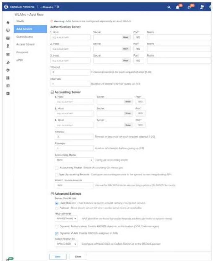
Groupwise Transient Key (GTK) per VLAN
The APs support dynamic VLAN via ePSK/RADIUS based/VLAN-pool feature on a given WLAN profile. client traffic is tagged as per the VLAN assigned dynamically. The unicast traffic works fine as each generates a unique PTK. However, the AP provides common GTK for all the clients associated with WLAN profile irrespective of the VLAN that belongs to. This causes all clients irrespective of the V assigned can receive broadcast/multicast data traffic of other VLAN traffic.
The solution is to generate the GTK per VLAN and forward it to clients as part of the WPA2 I that the broadcast/multicast data traffic is encrypted using GTK based on the VLAN tag of the packet maximum number of GTKs supported is 127 per radio. By default it is disabled.
cnMaestro configuration:
| AP Groups > Ent_Mesh_ZeroTouch_APGrp | |
| Dashboard Notifications Configuration Statistics Devices Clients Mesh Peers | |
| Basic | User-Defined Overrides |
| Management | Advanced configuration settings entered below will be applied on top of the AP Group settings sent to the device. This allows you to apply configuration not supported in the previous screens. If there are conflicts, the below settings will take precedence. The format used is the same as a configuration file exported from the device via its web UI or the "View Device Configuration" link in the device level configuration page. |
| Radio | Variables and Macros |
| Network | Settings entered are not validated or error-checked (However, dollar ($) , padad ( ) or space characters are not allowed in a variable name and it should not be more than 64 characters long), and they may overwrite configuration made in previous screens, so please use them with caution. You are responsible for ensuring the resulting AP Group is valid and safe to use. |
| Security | |
| Services | |
| User-Defined Overrides | wireless start! glo-pen-dan ! |
Dynamic ARP Inspection
Dynamic ARP Inspection detects and prevents ARP spoofing by validating ARP packets against a trust to-MAC address mapping. When a client sends an ARP packet, such as one claiming to be the system checks whether the claimed IP matches the client's registered IP in the wireless client table a mismatch, the packet is identified as spoofed and is dropped. Gateway IPs are learned dynamically DHCP packets (router option) during client associations, allowing the system to build a mapping tabl validation. It does not track gateway MAC addresses, as IP validation is sufficient for detecting sp
Spoofed ARP events are logged and visible via CLI commands, such as show events and show wireless spoofed-arp-stats.
This feature is available only as CLI command that you can configure in the AP Groups > User Overrides section in cnMaestro. A sample configuration snippet is shown below:
!
wireless wlan 1
dynamic-arp-inspection
!
Configuring the Network
This chapter describes the following topics
Overview
- Configuring Network parameters
Overview
This chapter gives an overview of the Enterprise Wi-Fi AP configuration parameters related to LAN, Routes, DHCP server, ACL, and Firewall.
Configuring Network parameters
Enterprise Wi-Fi AP network configuration parameters are segregated into the following sections:
• VLAN
- Routes
- Ethernet Ports
- Port Control—802.1X Authentication
• DHCP
- Tunnel
- PPPoE
• VLAN Pool
• Wireless Wide Area Network (WWAN)
IPv4 network parameters
VLAN

Note
By default, the XRP messages are sent through the native VLAN. From release version onwards, a new CLI command (roam management-vlan) is added to enable XRP messages to be sent through any VLAN other than the native VLAN. When configured, the roaming must have an L3 interface on the AP.
To configure network parameters, complete the following steps:
- Navigate to Configuration > Wi-Fi Profiles > AP Groups page.
-
Click Add New and select Enterprise Wi-Fi (E-Series, XE/XV/X7-Series) from the Type drop-down list.
-
Click Network tab > VLANs section.
Figure 39 Network > VLANs section

- Click Add New and configure the IPv4 parameters described in the following table.
Table 35 VLAN IPv4 parameters
| Parameters | Description Range Default | ||
| VLAN > IPv4 | |||
| Address Provision to configure the mode of IPv4 address configuration DHCP an interface selected. Two modes are supported:DHCP—This is the default mode in which the Enterprise Wi-Fi AP device tries to obtain an IPv4 address from the DHCP server.Static IP—Users must explicitly configure the IPv4 address and Netmask for a VLAN selected. | DHCP | ||
| NAT This option enables wireless traffic gets NAT'ed with APs respective uplink interface IP. This option is recommended when DHCP pools are configured in AP. | - Disabled | ||
| Zeroconf IP | Zeroconf IP is recommended to be enabled. This interface enabled available only in the VLAN1 configuration section. If VLAN 1 is not allowed in Ethernet interfaces, this IP will not be accessible. | ||
| DHCP Relay Agent | This option is enabled when DHCP server is hosted on DISVLAN which is not same as client that is requesting the DHCP IP. Enabling this appends Option 82 in the DHCP packets. Following information is allowed to configure:DHCP Option 82 Circuit IDConfigurable parameters under this option are as follows:HostnameAPMACBSSIDSSID | DISVLAN | |
CustomDHCP Option 82 Remote IDConfigurable parameters under this option are as follows:HostnameAPMACBSSIDSSIDCustom NoteIn case DHCP Option 82 is configured at the device-,WLAN profile-, and L3 interface-levels, the following priority order is considered:Device-level configurationWLAN profile-level configurationL3 interface-level configuration NoteIn case DHCP Option 82 is configured at the device-,WLAN profile-, and L3 interface-levels, the following priority order is considered:Device-level configurationWLAN profile-level configurationL3 interface-level configuration | Follows: | ||
| RequestOption All | This configuration decides the interface on which Enterprise AP will learn the following:IPv4 default gatewayDHCP client options like Option 43 and Option 15 (Controller discovery like controller host name / IPv4 address)DNS ServersDomain Name | Enactedon VLAN1 | |
Figure 40 VLAN IPv4 parameters

DHCP Client Options
Enterprise Wi-Fi AP devices learn multiple DHCP options for all VLAN interfaces configured on the Based on configured criteria, values of these options are used by the system. The below table lis different DHCP options.
Table 36 DHCP Options
| Options | Description Usage Reference | CLI | |
| Option 1 | The subnet mask option specifies client's subnet mask as per RF | Based on the state of “Request Option All”, the device chooses a subnet mask from the respective VLAN interface. | show ip route |
| Option 3 | This option specifies a list of addresses for routers on the subnet. | Based on the state of “Request Option All”, the device chooses a route learned from the respective VLAN interface. The only first route is honored. | show ip route |
| Option 6 | The domain name server option specifies a list of Domain Name System (STD 13, RFC 1035) name servers available to the client. SHOULD be listed in order of preference. | Based on the state of “Request Option All”, the device chooses subnet mask from the respective VLAN interface. the top two DNS servers are honored by Enterprise Wi-Fi AP devices. | show ip name-server |
| Option 15 | This option specifies the domain that the client should use when resolving hostnames via the Domain Name System. | More details are provided in Option 15. | show ip dhcp-client info |
| Option 26 | This option specifies MTU size network. | More details are provided in Configuring the Network. | show ip dhcp-client info |
| Option 28 | This option specifies the broadcast address that the client should address that the client should use LAN interfaces are used respectively as per standards | At broadcast address learned for all DHCP server while a request to get an IP address the DHCP server. | show ip dhcp-client-info |
| Option 43 | This option is used to help obtain the cnMaestro IP address from the DHCP server while a request to get an IP address the DHCP server. | More details are provided in Option 43 (cnMaestro On-Premises 2.4.0 DHCP Guide). is sent to | show ip dhcp-client info |
| Option 51 | This option is used in a client to allow the client to request time for the IP address. In a reply, a DHCP server uses this to specify the lease time it is offer. | Enterprise Wi-Fi AP renew leases for all VLAN interfaces configured serve lease time that has been from the DHCP server. willing to | show ip dhcp-based learned |
| Option 54 | DHCP clients use the contents server identifier field as the destination address for any DHCP messages unicast to the DHCP | Enterprise Wi-Fi AP learns DHCP server IP for all VLAN interfaces configured. server. | show ip dhcp-client info |
| Option 60 | This option is used by DHCP optionally identify the vendor type configuration of a DHCP client. | Enterprise Wi-Fi AP device, is updated as Cambium-Wi-Fi-AP. | show ip dhcp-client info |
DHCP Option 43—Zero-touch onboarding
This option is used to help the AP in obtaining the cnMaestro/XMS IP address from the DHCP s DHCP request to get an IP address is sent to the DHCP server.
This option is used to learn HTTPS proxy server address from the DHCP server as well.
DHCP Option 43 format
If HTTP proxy needs to be configured, then the following format must be used:
The cnMaestro/XMS URL and HTTPS proxy URL can be packed into Option 43 payload in a key-separated by ‘,’ like
For example,
0=CMBM;1=cloud.cambiumnetworks.com;2=http://user:userpass@IP/URL:port, where identifiers are listed below:
- 0 is for header CMBM - Mandatory
• 1 is for the server's URL
• 2 is for HTTP proxy URL

Note
If only cnMaestro URL configuration is needed then Option 43 payload can contain only too without key-value format as described above.
Routing and DNS
Table 37 AP Groups > Network > VLAN > Routes > IPv4 Routing and DNS parameters
| Parameters | Description Range Default | ||
| Default Gateway | Provision to configure the default gateway. If this is provided, Enterprise Wi-Fi AP device installs this gateway as this highest priority. | provided, is the | - |
| DNS Server | Provision to configure Static DNS server on Enterprise device. A maximum of two DNS servers can be configured. | Wi-Fi AP | - |
| Domain Name | Provision to configure Domain Name. If this is provided,- Enterprise Wi-Fi AP device installs this Domain Name as this is priority. | the highest | ise |
| DNS Proxy | Enterprise Wi-Fi AP device can act as DNS proxy server is enabled. NoteDNS Proxy is allowed only when NAT mode is enabled for the WLAN. NoteDNS Proxy is allowed only when NAT mode is enabled for the WLAN. | Disabled | this |
Figure 41 IPv4 Routing and DNS parameters

Routes
Below table lists the fields that are displayed in Configure > Network > Routes tab:
Table 38 IPv4 Gateway Source Precedence, Route entries, and Port forwarding parameters
| Parameters | Description Range Default | ||
| Gateway Source Precedence | Provision to prioritize default gateway and DNS servers Enterprise Wi-Fi AP device has learned from multiple ways. Default order is Static and DHCP. | wh Static. Default | |
| Add Multiple Route Entries | The user has provision to configure static Routes. Parameters that are required to configure static Routes are as follows:Destination IPMaskGateway | ||
| Port Forwarding | This feature is required when wireless stations are behind NAT. Users can access the services hosted on wireless stations using feature. Following configurable parameters are required to gain access to services hosted on wireless stations which are behind:PortIP AddressType | - this |
Figure 42 IPv4 Gateway Source Precedence, Route entries, and Port forwarding parameters

IPv6 network parameters
VLAN
Table 39 VLAN IPv6 parameters
| Parameters | Description Range Default | ||
| Address Provision to configure the mode of IPv6 address configuration for an interface selected. Five modes are supported:DisabledAutoConfigStaticStateless DHCPv6Stateful DHCPv6 | AutoConfig | ||
| Request Option All | This configuration decides the interface on which AP will learn the following: | - Enabled on VLAN1 | |
| IPv6 default gatewayDHCP client options like Option 52 and Option 24(Controller discovery like controller hostname / IPv6 address)DNS ServersDomain Name | |||
Figure 43 VLAN IPv6 parameters

Routing & DNS
Table 40 IPv6 Routing and DNS parameters
| Parameters | Description Range Default | ||
| Default Gateway | Provision to configure the default gateway. If this is provided, Enterprise Wi-Fi AP device installs this gateway as this highest priority. | provided, is the | - |
| DNS Server | Provision to configure Static DNS server on Enterprise device. A maximum of two DNS servers can be configured. | Wi-Fi AP | - |
| Domain Name | Provision to configure Domain Name. If this is provided,- Enterprise Wi-Fi AP device installs this Domain Name as this is the highest priority. | the highest | - |
| IPv6 Preference | When enabled, IPv6 is preferred over IPv4 based on response. | DNSDisabled | - |
Figure 44 IPv6 Routing and DNS parameters

Routes
Table 41 IPv6 Gateway Source Precedence and Multiple Route Entries parameters
| Parameters | Description Range Default | ||
| Gateway Source Precedence | Provision to prioritize default gateway and DNS servers Enterprise Wi-Fi AP device has learned from multiple ways. Default order is Static and AUTO-CONFIG/DHCPC. | when Static | |
| Add Multiple Route Entries | The user has provision to configure static Routes. Parameters that are required to configure static Routes are as follows:Destination IP/prefixGateway | meters that |
Figure 45 IPv6 Gateway Source Precedence and Multiple Route Entries parameters
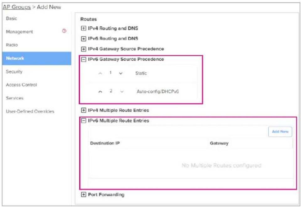
General network parameters
Table 42 VLAN - General parameters
| Parameters | Description Range Default | ||
| Management Access | Provision to restrict the access of devices in all (Telnet, SSH), GUI (HTTP, HTTPS), and SNMP. Users can configure restriction of device access as follows:BlockAllow from WiredAllow from both Wired and Wireless | modAllow | Cfrom both Wired and Wireless |
Select Management Access to configure restriction of the device from the drop-down list.
Figure 46 VLAN - General parameters

Ethernet Ports
Below table lists the fields that are displayed in AP Groups > Network > Ethernet Ports tab.
Table 43 Ethernet Ports 1 to 4 parameters
| Parameters | Description Range Default | ||
| Ethernet Port<1-4> | Enterprise Wi-Fi AP devices Ethernet port is provisioned operate in the following modes:Access Single VLAN—Single VLAN traffic is allowed in this mode.Trunk Multiple VLANs—Multiple VLANs are supported in this mode. | Access Single VLAN—Single VLAN traffic is allowed in this mode.Trunk Multiple VLANs—Multiple VLANs are supported in this mode. | Single VLAN |
| VLAN VLAN | ID to be associated with the Ethernet port. 1 to | 4094 | 1 |
| Port Speed | Specifies the port speed in Mbps.Following values are supported:Auto10 Mbps100 Mbps1000 Mbps2500 Mbps5000 Mbps | – Auto | |
| Port Duplex | Specifies the type of duplex communication configured– FullthDuplex port.Following values are supported:Full DuplexHalf Duplex | Duplex | |
| Tunnel Mode | Only applicable for Ethernet ports 2, 3, and 4.Specifies whether tunneling of wired traffic is enabled or not. |
Figure 47 Ethernet Ports parameters
Port Control—802.1X Authentication
802.1X authentication on Ethernet ports enhance the network security of the AP. The AP supports port-based authentication in the single-host authentication mode. In this mode, only one client is all access the network after successful 802.1X port-based authentication. After successful authentication, the port VLAN is assigned based on RADIUS assigned VLAN.

Note
- 802.1X port-based authentication does not support CoA messages.
802.1X port-based authentication requires a RADIUS AAA server for authentication and accounting.
The following table lists the parameters for configuring the RADIUS AAA server on Ethernet ports and on the AP Groups > Network > Ethernet Ports > RADIUS Server page.
Table 44 RADIUS Server parameters
| Parameters Description Range Default | |||
| Authentication Server | Specifies the authentication server details, such as:Host—IPv4 or IPv6 address or hostname of theSecret—Text string that is used to encrypt data packets shared between the AP and the sever.Text stringPort—Port number of the authentication server.A maximum of three RADIUS authentication servers configured. | - Disabled server in RADUS Format—Default—can be | |
| Accounting Server | Specifies the accounting server details, such as:Host—IPv4 or IPv6 address or hostname of theSecret-Text string that is used to encrypt data packets shared between the AP and the sever. Text stringPort-Port number of the accounting server. Default-1813A maximum of three RADIUS accounting servers can be configured. | - Disabled serverin RADUS Format- | US |
| Timeout Time | (in seconds) to wait for a response from the RADIUS server. | US-30 3 | |
| Attempts Number of retry attempts for contacting the RADIUS server. | 1-3 1 | ||
| Accounting Mode | Specifies the accounting mode to be used. The following modes are supported:Start-Stop-Accounting packets are transmitted by the AAA server when a wireless client is connected and when the client disconnects.Start-Interim-Stop-Accounting packets are transmitted by APs to the AAA server when a wireless client connects, then at regular intervals (configured in the Interim Update Interval field) and also when the client disconnects.None-Disables the accounting mode. This is the default mode. | None (Disabled) | |
| Server Pool Mode | Users can configure multiple Authorization and Accounting Failover servers. Based on a number of wireless stations, the user choose Failover mode.Load Balance-AP equally distributes the requests between the configured RADIUS servers,Failover-AP selects the RADIUS server that is functional based on the order of configuration. | Functional can | |
| Interim update interval | Time (in seconds) to wait for sending RADIUS interim accounting update packets.Note: This interval is applicable only when you select the Start-Interim-Stop option in the Accounting Mode parameter. | 0-65535 | 1800 |
| Dynamic Authorization | This option is required, where there is CoA request- disabled AAA/RADIUS server. | Disabled | |
Figure 48 RADIUS Server parameters
![AP Groups > Add New Basic Management Radio Network Security Access Control Services User-Defined Overrides RADIUS Server Authentication Server 1. Host Secret Port* Show 18/2 2. Host Secret Port* Show 18/2 3. Host Secret Port* Show 18/2 Timeout 3 Traout in seconds for each request attempt (1-30) Attempts 1 Number of attempts before giving up (1-3) Accounting Server 1. Host Secret Port* Show 18/3 2. Host Secret Port* Show 18/3 3. Host Secret Port* Show 18/3 Timeout 3 Traout in seconds for each request attempt (1-30) Attempts 1 Number of attempts before giving up (1-3) Accounting Mode None Configure accounting mode Server Pool Mode ● Load Balance Load balance requests equally among configured servers ○ Follower Move down server list when earlier servers are unreachable Interim Update Interval 100 Interval for RADIUS Interim-Accounting updates [10-65535 Seconds] ✓ Dynamic Authorization Enable RADIUS dynamic authorization (COA, DM messages)](/content/2026/05/908365/images/8a80ffafef0aaae956998e11868e45d0910ee762776d34e91060fffe06f32f40.jpg)
DHCP
Below table lists the fields that are displayed in the AP Groups > Network > DHCP page.
Figure 49 DHCP Pool parameters

Table 45 DHCP parameters
| Parameters | Description Range Default | ||
| DHCP Pool | Specifies the DHCP pool ID. 1 to 16 - | ||
| Address Range | Indicates the start and end addresses for the DHCP Pool. - - | ||
| Default Router | Specifies the default router IP address. - - | ||
| Domain Name | Specifies the domain name for the DHCP pool. - - | ||
| DNS Address | Specifies the primary and secondary addresses of the for a DHCP pool. | DNS server | |
| Network Specifies | ifies the network IP address and subnet mask for the DHCP pool. | - | - |
| Lease Duration | (in days, hours, and minutes) for which the IP address be leased to the client. | - | - |
| Add Bind List | |||
| For every DHCP pool configured, the user can bind MAC and the address pool defined, so that the wireless station gets the IP address every time they connect. Following parameters are required to bind IP address:MAC AddressIP Address | - | IP from same | |
Figure 50 Add DHCP window

Tunnel
The following table lists the fields that are displayed in AP Groups > Network > Tunnel page.
Figure 51 Tunnel - L2TP parameters

Figure 52 Tunnel - L2GRE parameters
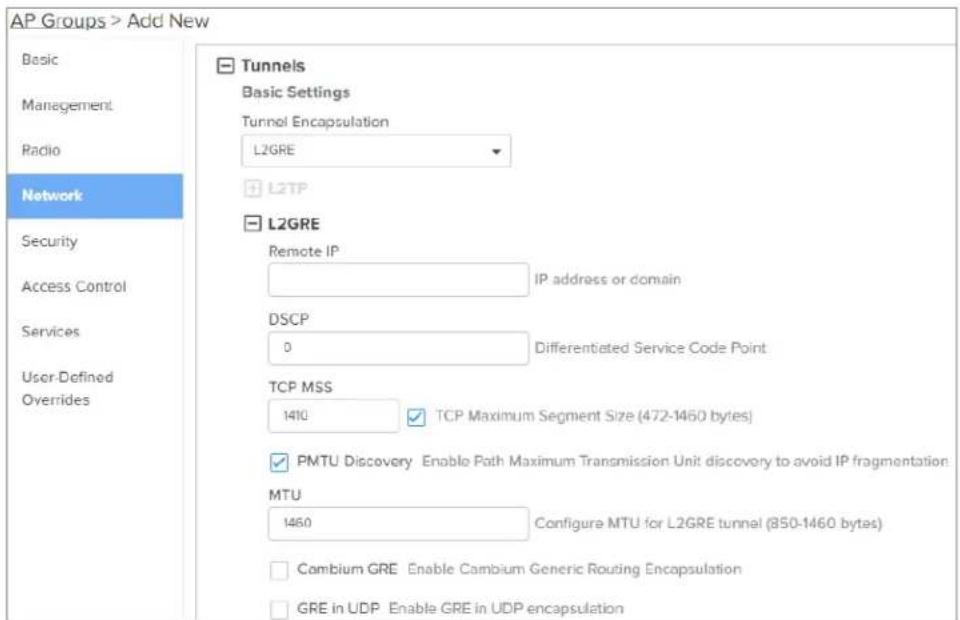
Table 46 Tunnel parameters
| Parameters Description Range Default | |||
| Tunnel Encapsulation | Provision to enable tunnelFollowing tunnel types aresupported by Enterprise Wi-Fi devices:L2TPL2GREOFF | typeOFFAP | |
| L2TP | |||
| Remote IP Configure | L2TP end point. IPv4address or Primary hostname ofthe endpoint is supported. | - | - |
| Username andPassword | Credentials required for L2TP- admin/adminauthentication. | ||
| Authentication Type | Provision to select the PPP authentication method.Following are the options available:DEFAULTCHAPMS-CHAPMS-CHAPv2PAP | - DEFAULT | |
| TCP MSS TCP Maximum Segment Size(MSS) in bytes. | 422- 1410 1400 | ||
| PMTU Discovery Provision to enable to discover PMTU in network. | - Enabled | ||
| L2GRE-1You can configure a maximum of two L2GRE tunnels. Configure L2GRE-1 tunnel by parameters in the AP Groups > Network > Tunnel tab. However, configuring L2GRE-2 tunnel is allowed only using the device CLI. The following parameters for L2GRE-1 are also applicable | |||
| Remote IP Configure L2GRE endpoint. IPv4 address or primary hostname of an endpoint is supported. | - | - | |
| DSCP Users can configure priority of GRE packets. | - 0 | ||
| TCP MSS TCP Maximum Segment Size (MSS) in bytes. | 472-1460 1410 | ||
| PMTU Discovery Provision to enable to discover PMTU in a network. | - | - | |
| MTU Maximum Transmission Unit in bytes. | 850-1460 1460 | ||
| GRE in UDP GRE | protocol is designed to establish a tunnel between third-party vendor which complies with RFC 8086. | - Disabled any | |
Point-to-Point Protocol over Ethernet (PPPoE)
PPPoE provides the ability to establish a connection to ISP with user authentication. Below table lists fields that are displayed in AP Groups > Network > PPPoE page.
Figure 53 PPPoE parameters

Table 47 PPPoE parameters
| Parameters Description Range Default | |||
| Enable Provision to enable PPPoE client. - Disabled | |||
| VLAN ID Users can configure VLAN ID where PPPoE clients should obtain an IP address. | ould | - | |
| Service Name | Configure PPPoE service name. -- | ||
| Authentication Info | Provision to configure credentials required for PPPoE authentication. | admin/admin | |
| MTU Maximum | Transmission Unit. 500- | 1492 | 1492 |
| TCP-MSS Clamping | Configure PPPoE endpoint. Either IP or hostname endpoint is supported. | of Enabled | |
| Management Access | If enabled, the user can access the device either - disabled or SSH with PPPoE IP. | - disabled or | |
VLAN Pool
The following table lists the fields that are displayed in AP Groups > Network > VLAN Pool page.
Table 48 The VLAN Pool parameters
| Parameters | Description | Range | Default |
| VLAN Pool Name | Name for the VLAN pool. | - | - |
| VLAN ID List | List of VLAN IDs for the VLAN pool.You can configure either a single VLAN ID or multipleMultiple VLAN IDs can be configured either separated by comma or hyphen. For example, 2-7, 45, 67. | -VLAN IDs. | - |
Figure 54 The VLAN Pool parameters

Wireless Wide Area Network (WWAN)
The following table lists the fields that are displayed in Configure > Network > WWAN tab.

| Note |
| This feature is supported in XV2-2, XV3-8, XE3-4, and XE5-8 platforms only. |
Table 49 WWAN parameters
| Parameters Description Range Default | |||
| WWAN Provision to enable wireless WAN using a USB cellular dongle for internet access. | - | - | |
| Failover Only | Failover only can be configured in two modes:Enabled: Ethernet will be the primary connection and WWAN will be backup.Disabled: 3G/4G (WWAN) will be the only working connection.Note: Cellular link can be configured as backupEthernet connection. | - Enabledonly to | |
| APN Provision | to configure network provider APN address. - - | ||
| Authentication Info | Provision to configure credentials required for WWAN admin/admin authentication. | ||
| Monitor Host | Running a check in the background that constantly-a user configured IP address (example: 8.8.8.8) for reachability through ping. | -monitors- | |
To configure the above parameter, login to cnMaestro AP Group > Network > WWAN tab and provide the details as given below:
- Enable WWAN check box to enable this functionality.
- Check/Uncheck Failover Only to enable/disable.
- Enter the APN address in the text box.
- Enter the Authentication credentials.
- Enter any IPv4 address to Monitor Hoist text box.
- Click Save.
Figure 55 WWAN parameters

Supported hardware
Cambium Networks currently support the following models, where local laws permit:
- Huawei
E8372
E3372
- Alcatel
- Link Key 4G IK40V (recommended)
• ZTE
MF833V
Configuring Access Control
The Access Control page allows the users to enable or assign access control policies and configur group policies and device policies. It offers visibility into the configured rules, ensuring efficient and network management.
Figure 56 Access Control page


Note
If an Access Control Policy is assigned at the AP group level, it does not appear unGroup or Device Group policies.
This chapter describes the following topics
• Enabling Access Control Policy
- User Group Policy
• Device Policy
Enabling Access Control Policy
Users have the provision to enable or disable access control policies under Access Control tab.
Figure 57 Enabling Access Control Policy

Users can select the available access control policies listed in the Wi-Fi profiles in the Access Control Policy drop-down list. They can also view the configured rules associated with these policies by clicking View Rules. This provides a comprehensive view of the policies and rules within the network.
Figure 58 Access Control Policy Rules

User Group Policy
User group policies allow you to categorize users into specific roles with customized access permissions and restrictions, facilitating a fine-tuned control over network access.
To add a new to User Group Policy, perform the following steps:
- Navigate to Configuration > Wi-Fi Profiles > AP Groups > Access Control page.
- Click Add to create a new AP group.
- Click the Access Control tab in the Add New page.
- Click Add New in the User Group Policy section.
Figure 59 User Group Policy

- Complete the details in the Add User Group window.
Figure 60 Add User Group
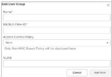

Note
- The user must assign an Access Control Policy or VLAN to create a User Group
• A maximum of 64 User Group Policies are supported.
- Users can select Access Control Policies with non-MAC filters only from the Access Control Policy drop-down list.
- Mapping an Access Control Policy to a User Group Policy enables its use for the group, and vice versa. However, the same Access Control Policy cannot be shared between the User Group Policy and the AP group. You can apply it either to the Group Policy or to the AP group only.
Device Policy
Device Policy allows users to apply specific rules and access control policies based on the type a characteristics of devices, offering customized control over device behavior within the network.
To add a new Device Policy, perform the following steps:
- Navigate to Configuration > Wi-Fi Profiles > AP Groups tab.
- Click Add to create a new AP group.
- Click the Access Control tab in the Add New page.
- Click Add New in the Device Policy section.
Figure 61 Device Policy

- Complete the details in the Add Device Policy window.
Figure 62 Add Device Policy


Note
• A maximum of 64 Device Policies are supported.
- Users can select Access Control Policies with non-MAC filters only from the Access Control Policy drop-down list.
Managing Filters
This chapter describes the following topics:
- Overview
- Filter list
• Device class filter
• Wi-Fi Calling support - Air cleaner
• Application control Premium feature
Overview
Filters are used to define the rules used for blocking or passing traffic and also to change QoS/ rate-limiting for selected traffic.
The Wireless AP's integrated firewall uses stateful inspection to accelerate the decision of whether t or deny traffic user connections managed by the firewall are maintained statefully. Once user flow established through the AP, it is recognized and passes through without the application of all defin filtering rules. Stateful inspection runs automatically on the AP.
Filter list
Filters are organized in groups, called filter lists. A filter list allows users to apply a uniform set SSIDs. AP supports 16 filter lists and each filter list supports 50 filter rules in precedence order.
Filters
These settings create and manage filters with precedence that belong to the current filter list, base filter criteria you specify.
Filters can be configured in Layer 2 and Layer 3 or application/category control (Layer 7). Layer 2 high precedence over Layer 3 application control and Layer 2 supports MAC/IP/protocol-based rules.
Filters are an especially powerful feature when combined with the intelligence provided by the Application
Control Windows.
Based on Application Control's analysis of your wireless traffic, you can create filters to enhance w usage for your business needs:
- Usage of non-productive and risky applications like BitTorrent can be restricted.
-
Traffic for mission-critical applications like VoIP and WebEx may be given higher priority (QoS).
-
Non critical traffic from applications like YouTube may be given lower priority (QoS) or bandwidth allowed may be capped per station or for all stations.
Configuring filter CLI
By configuring the filter CLI, the user can define ACL rules for blocking or passing traffic, DSCP/G modifying packets, and rate-limiting for selected traffic.
- Create filter list/filter profile using global filter command (Filter: configure filter parameters).
ap(config)# filter
filter-list : Configure filter list
global-filter : Configure Global filter parameters
- Global-filter is for global rules in AP. Global-filter includes the below options:
ap(config-global-filter)#
air-cleaner : Configure Preset air cleaner filters
application-control : Enable application control
clear : Clear command
disable : Disable filter list
filter : Configure filter rules in precedence order
stateful : Enable stateful filtering
apply : Apply configuration that has just been set
exit : Exit from filter list configuration
no : Delete/disable filter list parameters
save : Save configuration to Flash so it persists across reboots
show : Show command
- Stateful filtering : Stateful operation of the integrated firewall can be Enabled or Disabled. By default, it is enabled.
- Application Control: Operation of the Application Control feature may be Enabled or Disabled.
-
Disable: Disable or enable filter list.
-
Each filter list includes below options:
clear : Clear command
disable : Disable filter list
filter : Configure filter rules in precedence order
name : Name of filter list

apply : Apply configuration that has just been set
exit : Exit from filter list configuration
no : Delete/disable filter list parameters
save : Save configuration to Flash so it persists across reboots
show : Show command

Note
Global-filter rules will take precedence over filter-list rules
- Global filter and filter-list can include 50 filter rules with precedence order.
ap(config-filter-list-1)# filter precedence {1-50}
- Then create filter rule from precedence level (1 to 50).
(config-list-1-filter-precedence-1)# exit
(config-filter-list-1)# filter precedence 1
(config-list-1-filter-precedence-1)#

application-control : Configure application control filters
category-control : Configure application category control filters
clear : Clear command
disable : Disable filter
layer2-filter : Configure Layer2 filter
layer3-filter : Configure Layer3 filter
logging : Enable filter logging
rate-limit : Set traffic limit for this filter
schedule : Schedule Layer3 rules
wlan-to-wlan : Restrict 'in' direction rule's egress direction as wlan

apply : Apply configuration that has just been set
exit : Exit from custom filter configuration
no : Disable the filter options
save : Save configuration to Flash so it persists across reboots
show : Show command

Note
The filter type is either Layer 2 or Layer 3 or application control can be added in o precedence level.
- Layer 3 filter has the below provisions.
(config-list-1-filter-precedence-1)# layer3-filter

deny : Drop packet matching the rule
permit : Allow packet matching the rule
set-dscp : Set DSCP value to packet matching the rule
set-qos : Set QOS value (0-3) to packet matching the rule
- QoS Premium feature: Set packets QoS level (0 to 3). Level 0 has the lowest priority; level 3 highest priority
- DSCP Premium feature Differentiated Services Code Point or DiffServ (DSCP). DSCP level (0 to 63. Level 0 has the lowest priority and level 63 has the highest priority.
- Rate limit Premium feature: Filters support rate limiting per station or all stations and support Kbps/Mbps/pps.
- Schedule Premium feature: Filter support scheduling the activation of the layer3 /application control rules based on the day and local time selected.
- Disable: Each filter and filter list can be turned on/off.

Note:
Application Control, QoS, DSCP, Schedule and Rate limit are Premium features.
- Each layer 3 rule category has below types
(config-list-1-filter-precedence-1)# layer3-filter set-dscp
ip : IPV4 address based rule
ip6 : IPV6 address based rule
proto : Protocol based rule
proto6 : IPv6 Protocol based rule
- For proto or port number-based rule, select proto.
(config-list-1-filter-precedence-1)# layer3-filter set-dscp proto
layer3-filter set-dscp proto (tcp|udp|icmp|igmp|srp|sctp|any) (SOURCE-IP/{mask|prefix-length}}|any) (SOURCE-PORT|any) (DESTINATION-IP/{mask|prefix-length}}|any) (DESTINATION-PORT|any) (in|out|any) (DSCP{0-63}) <(optional)//Filter_name>

Note
All fields are mandatory. If no parameter to configure, give 'any'. direction of the rule. if it is 'in', the rule is applicable for traffic. If it is 'out', the rule is applies for traffic to wireless.
Direction is the from the wireless sid
- For non-proto or port number-based rules, select IP.
(config-list-1-filter-precedence-1)# layer3-filter set-dscp ip
layer3-filter set-dscp ip (SOURCE-IP{//mask|prefix-length}|any) (DESTINATION-IP{//mask|/prefix-length}|any) (in|out|any) (DSCP{0-63}) <(optional)//Filter_name>
- Layer 2 filter has below options:
(config-list-1-filter-precedence-11)# layer2-filter
deny : Drop packet matching the rule
permit : Allow packet matching the rule
- Each layer 2 rule category has below two cases.
(config-list-1-filter-precedence-11)# layer2-filter permit
mac : Mac or IP based Rule with out Protocol
proto : Mac or IP based rule with Protocol
Layer 2 rule supports IP, MAC, Port, or Protocol-based rules.
- ap(config-list-1-filter-precedence-1) # layer2-filter permit mac
(config-list-1-filter-precedence-1)# layer2-filter permit mac
layer2-filter permit mac (SOURCE-MAC/IPv4/IPv6{(optional)/{mask|prefix-length}}|any)(DESTINATION-MAC/IPv4/IPv6{(optional)/{mask|prefix-length}}|any) (in|out|any) <(optional)//Filter_name>
Example:
e.g. layer2-filter permit mac 00-01-02-03-04-05 00-01-02-09-08-07 any //filter_to_allow_guest
'!!' for not e.g. layer2-filter permit mac 00-01-02-03-04-05 !00-01-02-09-08-07 out
layer2-filter permit mac !1.1.1.1/8 any any
- ap(config-list-1-filter-precedence-1) # layer2-filter permit proto
(config-list-1-filter-precedence-1)# layer2-filter permit proto
layer2-filter permit proto (tcp|udp|arp|icmp|igmp|srp|sctp|any) (SOURCE-MAC/IPv4/IPv6/{mask|prefix-length})|any) (SOURCE-PORT|any) (DESTINATION-MAC/IPv4/IPv6/{mask|prefix-length})|any) (DESTINATION-PORT|any) (in|out|any) <(optional)//Filter_name>
Example:
e.g layer2-filter permit proto tcp any any 10000 any //filter_permit_guest
'!! for not e.g layer2-filter permit proto tcp any any !00-00-11-11-11-11 10000 out
layer2-filter permit proto tcp 1.1.1.1 1000 00:11:22:33:44:44/ff-ff-ff-00-00-00 5000 any
Sample configuration
filter global-filter
stateful
application-control

filter filter-list 1
    filter precedence 1
    layer3-filter set-qos ip any 9.9.9.9 in 2
    rate-limit all Mbps 500
    exit
    filter precedence 2
    layer3-filter deny ip 5.5.5.5 6.6.6.6 any
    exit
    filter precedence 3
    layer3-filter permit ip any any any
    exit
    filter precedence 4
    layer3-filter permit ip 9.9.9.9 any any
    exit
- To attach the filter list into the WLAN profile, filter-list < filter-list ID>.
wireless wlan 1
ssid cambium-guest
no shutdown
vlan 1
filter-list 1
- To show filter statistics:
(config)# show filter-statistics
Filter ID | global
Device class filter
This feature applies wireless policies to the client-based device class (notebook, phone, tablet, and its type (Windows, Mac, and Android).
CLI configuration:
ap(config)# device-class-filter 1
ap(config-device-class-filter-1)# class
ap : Configure filter rules for the AP device class
appliance : Configure filter rules for the appliance device class
desktop : Configure filter rules for the desktop device class
game : Configure filter rules for the game device class
notebook : Configure filter rules for the notebook device class
phone : Configure filter rules for the phone device class
player : Configure filter rules for the player device class
tablet : Configure filter rules for the tablet device class
ap(config-device-class-filter-1)# class notebook
all : Configure filter rules for all notebook device classes
chrome : Configure filter rules for the Chrome-OS device type
linux : Configure filter rules for the Linux device type
mac : Configure filter rules for the Mac device type
windows : Configure filter rules for the Windows device type
ap(config-device-class-filter-1)# class notebook linux
ap(config-device-class-filter-1)# filter-list
Filter list ID <1-16> or Name
Wi-Fi Calling support
Cambium Networks Access Point has the inbuilt application visibility engine, which can detect Wi-Fi and provide better call quality by reducing the latency, jitter, and roaming delays for voice calls of
When the Access Point detects the Wi-Fi calling traffic, it classifies and puts the traffic in the voi queue for achieving better call quality.
CLI configuration:
filter precedence 5
application-control wificall set-qos 3

Note
Filter precedence can be from 1 to 50.
Air cleaner
The Air Cleaner feature offers several predetermined filter rules that eliminate a great deal of unne wireless traffic.
Configuration CLI:
ap(config)# filter global-filter
ap(config-global-filter)# air-cleaner
all : All air cleaner filters
arp : Eliminate station to station ARPs over the air
broadcast : Eliminate broadcast traffic from the air
dhcp : Eliminate stations serving DHCP addresses from the air
multicast : Eliminate chatty multicast traffic from the air
When we configure the Air Cleaner rule, pre-defined filter rules will get popular shown below:
ap(config-global-filter)# air-cleaner all
ap(config-global-filter)# show config filter
!
!
filter global-filter
stateful
application-control
air-cleaner all
filter precedence 1
layer2-filter deny proto arp any any in //Air-cleaner-Arp.1
wlan-to-wlan
exit
filter precedence 2
layer2-filter deny proto udp any any FF:FF:FF:FF:FF:FF 67 out //Air-cleaner-Dhcp.1
exit
filter precedence 3
layer2-filter deny proto udp any any FF:FF:FF:FF:FF:FF 68 in //Air-cleaner-Dhcp.2
exit
filter precedence 4
layer2-filter permit proto arp any FF:FF:FF:FF:FF:FF any //Air-cleaner-Bcast.1
exit
filter precedence 5
layer2-filter permit proto udp any any FF:FF:FF:FF:FF:FF 67 any //Air-cleaner-Bcast.2
exit
filter precedence 6
layer2-filter permit proto udp any any FF:FF:FF:FF:FF:FF 68 any //Air-cleaner-Bcast.3
exit
filter precedence 7
layer2-filter permit proto udp any any FF:FF:FF:FF:FF:FF 22610 any //Air-cleaner-Bcast.4
exit
filter precedence 8
layer2-filter deny mac any FF:FF:FF:FF:FF:FF any //Air-cleaner-Bcast.5
exit
filter precedence 9
layer2-filter permit mac any 01:00:5E:00:00:FB any //Air-cleaner-mDNS.1
exit
filter precedence 10
layer2-filter deny mac any multicast any //Air-cleaner-Mcast.1
exit

Note
In Mesh link configuration, the Air Cleaner rules need customization like disabling Precedence 2 and Precedence 3 (DHCP rules).
Application control Premium feature
The Application Control feature provides real-time visibility of application usage by users across the network. Network usage has changed enormously in the last few years, with the increase in smart tablet usage stressing networks. Increasing traffic from legitimate business needs such as cloud- and based applications, streaming media, and VoIP must be handled with an adequate quality of experie achieve this purpose Application Control filters are used to define the rules used for blocking or change QoS/DSCP and rate-limiting for the specific Application or a specific category of application. more details, refer to the Application Control Filters section in the user guide
Application Control can track application usage over time to monitor trends. Usage may be tracked VLAN, or station. Many hundreds of applications are recognized and grouped into a number of cat. The distributed architecture of Cambium Enterprise APs allows Application Control to scale naturally a grow the network.
This topic describes the following content:
• Deep Packet Inspection (DPI)
• Application control policy
- Risk and productivity
Selection criteria
- DPI CLI configuration
- Global application policy
- SSID application policy
- Custom Applications X
Deep Packet Inspection (DPI)
The AP uses Deep Packet Inspection (DPI) to determine what applications are being used and by how much bandwidth they are consuming. These applications are rated by their degree of risk and productiveness. Filters can be used to implement per-application policies that keep network usage focus on productive uses.
Application control policy
When you find risky or unproductive applications consuming bandwidth on the network, you can ease create Filters to control them. You may use filters to:
- Block problematic traffic, such as BitTorrent or Y8.
- Prioritize mission-critical traffic: By increasing the QoS assigned to the traffic, applications like Vol WebEx may be given higher priority (QoS).
- Lower the priority of less productive traffic: Use filters to decrease the QoS assigned to traffic applications like YouTube and Facebook.
- A nonproductive specific application can be rate-limited to avoid impact on the productive application (for example, YouTube streaming can be rate-limited to avoid impact on applications like VoIP)
Risk and productivity
Application control ranks applications in terms of their levels of risk and productivity.
Productivity: Indicates how appropriate an application is useful for business purposes. The higher the number, the more business-oriented an application is:
- Primarily recreational
- Mostly recreational
- Combination of business and recreational purposes
- Mainly used for business
- Primarily used for business
Risk: indicates how likely an application is to pose a threat to the security of your network. The rating number, the riskier of an application is:
- No threat
- Minimal threat
- Some risk: maybe misused
- High risk: maybe malware or allow data leaks
- Very high risk: threat circumvents firewalls or avoids detection
Selection criteria
From the AP CLI, the below options are available to view the Application Statistics:
- Application: This gives detailed information about the application seen from the wireless traffic.
- Category: This gives the combined statistics of the application which belongs to a particular category (for example, Games, Network monitor).
| Config)# show application-statistics by-application | ||||||
| Applications Count = 24 | ||||||
| Application Statistics for All Applications | ||||||
| Protocol or Application | Productivity Index & Risk | TX Packets | TX Bytes | RX Packets | RX Bytes | |
| Ad Analytics | 4 | 1 | 4 | 220 | 3 | 231 |
| Amazon | 2 | 1 | 75 | 31437 | 69 | 8337 |
| Bonjour | 4 | 1 | 15 | 1737 | 14 | 1664 |
| Doubleclick | 1 | 1 | 84 | 30190 | 65 | 12228 |
| Google Ads | 3 | 1 | 103 | 47136 | 78 | 12223 |
| Google Analytics | 4 | 1 | 13 | 3750 | 15 | 1711 |
| Google APIs | 3 | 1 | 4713 | 6288091 | 892 | 153251 |
| 3 | 1 | 2544 | 3248915 | 568 | 48664 | |
| Google Play | 3 | 1 | 350 | 396456 | 181 | 15261 |
| Mozilla | 3 | 1 | 54 | 44708 | 48 | 5854 |
| NetBIOS NS | 1 | 3 | 0 | 0 | 12 | 936 |
| NTP | 1 | 3 | 2 | 152 | 2 | 152 |
| OCSP | 3 | 1 | 63 | 6404 | 71 | 5247 |
| OpenX | 1 | 1 | 32 | 8374 | 27 | 3507 |
| Quantcast | 1 | 1 | 14 | 4733 | 17 | 2341 |
| Rapleaf | 3 | 1 | 19 | 6745 | 19 | 2288 |
| 3 | 1 | 1227 | 1477596 | 752 | 74695 | |
| Scorecard Research | 1 | 1 | 26 | 5876 | 27 | 2748 |
| SSDP | 4 | 1 | 329 | 146086 | 20 | 4000 |
| SSL | 3 | 3 | 226 | 136435 | 176 | 22509 |
| TCP | 3 | 1 | 2376 | 1617471 | 1665 | 330377 |
| 3 | 4 | 79 | 53301 | 68 | 7532 | |
| Wikipedia | 3 | 3 | 19 | 3126 | 28 | 3873 |
| YouTube | 1 | 4 | 95 | 26393 | 99 | 12233 |
ap(config)# show application-statistics by-category Application Categroy Statistics for All Applications
Application Productivity TX TX RX RX category Index & Risk Packets Bytes Packets Bytes
File-Transfer 1 1 81 17881 0 0 Mail 3 1 1351 1057897 1318 155897 Messaging 2 2 633 245164 558 68508 Network-Monitoring 3 4 43 2580 1 60 Networking 3 1 51911 4422799 2524 1488418 Proxy 2 2 8637 7892737 6454 1008520 Social-Networking 2 3 52038 68131289 19772 2285979 Streaming-Media 2 3 15030 18700791 9156 1366044
Web-Services 2 2 38872 26757562 32219 7094216
- SSID: This gives the application list seen on a particular SSID. The SSID number is the BSS index configured.
ap(config)# show application-statistics by-application ssid 1
Applications Count = 79
Application Statistics for wlan index 1

================

Protocol or Productivity TX TX RX RX
Application Index & Risk Packets Bytes Packets Bytes

================

Ad Analytics 4 1 221 113639 204 27874
Admeta 4 1 20 8577 17 3470
Aggregate Knowledge 4 1 72 25718 67 11423
Amazon 2 1 1245 773227 1307 413188
Amazon Web Services 1 2 2102 2543236 1522 111343
Amp 4 1 163 144673 157 16258
AOL Ads 3 1 21 11459 24 3769
Appier 4 1 39 13552 26 5046
AppNexus 1 1 172 72763 167 62363
Bing 3 1 17 8140 12 1175
Bluekai 1 1 35 13127 23 2856
Bonjour 4 1 0 0 1067 332560
Casale 3 1 97 36559 85 12244
CloudFlare 3 2 31 12537 20 2286
Captive Network Ass 2 1 18 1194 10 918
Connexity 3 1 22 13348 27 3954
Contextweb 4 1 81 41240 100 20963
Criteo 4 1 376 171618 396 60013
Crashlytics 1 1 74 29571 82 10660
Doubleclick 1 1 3549 2691946 2587 759544
DHCP 4 1 52 17212 0 0
Dotomi 4 1 59 21308 64 8324
Drawbridge 4 1 28 6164 23 4780
Facebook 2 1 6053 5188935 4732 1217723
Facebook Messages 2 2 202 71996 150 18393
Facebook Video 2 3 44585 61497202 14049 941942
Flurry 3 1 17 5694 27 15624
Font Awesome 4 1 94 98415 88 5341
gmail 3 1 1351 1057897 1318 155897
Google Ads 3 1 1356 903620 1066 123597
Google Analytics 4 1 475 165753 407 91298
Google APIs 3 1 5437 2829186 4775 1605169
GoogleDuo 4 1 84 22238 82 23226
Google 3 1 5381 3955811 4385 799374
Google Play 3 1 980 242763 880 254459
Google Video 2 2 0 0 20 23771
hotstar 1 4 100 64443 82 21328
HTTP 3 1 1184 371037 1100 173347
HTTP 2.0 3 1 1410 360603 1271 232993
HTTP VIDEO 3 2 3801 5360601 1841 105901
HWCDN 3 1 213 259756 200 12745
ICICI Bank 2 2 29 33613 21 2025
ICMP 3 4 5 300 1 60
Instagram 1 1 322 330979 242 33346
Krux 1 1 71 31719 53 6993
Lotame 1 1 109 63865 84 10168
MDNS 3 1 0 0 86 21324
Media Innovation Gr 3 1 45 14819 40 5662
Media Math 1 1 25 5413 8 1034
Mixpanel 3 1 451 139375 496 275463
NrData 4 1 371 56753 341 108525
NTP 1 3 1 76 1 76
OpenX 1 1 113 20680 86 12298
Outbrain 3 1 34 16363 46 6344
OwnerIQ 3 1 38 8977 29 5783
Paytm 2 3 2015 2201287 1177 146483
Psiphon 2 2 8562 7869967 6392 983509
PubMatic 3 1 331 103338 262 57072
Quantcast 1 1 47 23413 47 9495
Quic 3 1 0 0 817 1052805
Rapleaf 3 1 66 28602 65 8000
Rubicon Project I I I I I I I I I I I I I I I I I I I I I I I I I I I I I I I I I I I I I I I I I I I I I I I I I I I
Scorecard Research 1 1 96 35762 90 12758
Smart AdServer 3 2 35 13345 45 6116
SpotXchange 3 2 59 14418 49 14522
SSDP 4 1 0 0 287 43911
SSL 3 3 6029 4347809 5173 1029629
Taboola 3 2 2177 2715316 1082 123164
TCP 3 1 169 37436 194 26160
The Trade Desk 3 1 101 67145 67 13168
Turn 1 1 71 31424 81 9438
Twitter 3 4 867 1040706 593 73816
UDP 3 1 0 0 62 10664
Ultrasurf 2 2 31 10286 19 1848
WhatsApp Media Mess 2 2 145 167080 135 10680
WhatsApp 2 2 404 55846 341 34602
Xiaomi 3 1 1244 718018 1376 285219
Yahoo 3 3 204 77608 251 48694
YouTube 1 4 11031 13254451 7129 1156065
- Display for Station: This gives detailed information about a particular station. Provide the station MAC address the user wants to check for statistics.
- Tx means downlink traffic concerning AP and Rx mean uplink traffic with respect to AP.
| (config)# show application-statistics by-application station D4-6A-6A-E7-D0-15Applications Count = 24Application Statistics for station D4-6A-6A-E7-D0-15 | ||||||
| Protocol or Application | Productivity Index & Risk | TX Packets | TX Bytes | RX Packets | RX Bytes | |
| Ad Analytics | 4 | 1 | 4 | 220 | 3 | 231 |
| Amazon | 2 | 1 | 75 | 31437 | 69 | 8337 |
| Bonjour | 4 | 1 | 0 | 0 | 15 | 1810 |
| Doubleclick | 1 | 1 | 84 | 30190 | 65 | 12228 |
| Google Ads | 3 | 1 | 103 | 47136 | 78 | 12223 |
| Google Analytics | 4 | 1 | 13 | 3750 | 15 | 1711 |
| Google APIs | 3 | 1 | 4713 | 6288091 | 892 | 153251 |
| 3 | 1 | 2544 | 3248915 | 568 | 48664 | |
| Google Play | 3 | 1 | 387 | 404916 | 215 | 20326 |
| Mozilla | 3 | 1 | 117 | 67446 | 104 | 12051 |
| NetBIOS NS | 1 | 3 | 0 | 0 | 12 | 936 |
| NTP | 1 | 3 | 2 | 152 | 2 | 152 |
| OCSP | 3 | 1 | 63 | 6404 | 71 | 5247 |
| OpenX | 1 | 1 | 32 | 8374 | 27 | 3507 |
| Quantcast | 1 | 1 | 14 | 4733 | 17 | 2341 |
| Rapleaf | 3 | 1 | 19 | 6745 | 19 | 2288 |
| 3 | 1 | 1235 | 1478487 | 761 | 77186 | |
| Scorecard Research | 1 | 1 | 26 | 5876 | 27 | 2748 |
| SSDP | 4 | 1 | 0 | 0 | 28 | 5600 |
| SSL | 3 | 3 | 226 | 136435 | 176 | 22509 |
| TCP | 3 | 1 | 2770 | 1675214 | 2075 | 424531 |
| 3 | 4 | 79 | 53301 | 68 | 7532 | |
| Wikipedia | 3 | 3 | 19 | 3126 | 28 | 3873 |
| YouTube | 1 | 4 | 113 | 32330 | 116 | 15918 |
Below CLI command gives a list of stations present along with station count per VLAN.
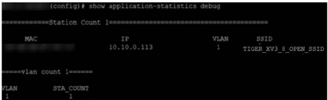
ap(config)# show application-statistics debug
==================Station Count 3==================
MAC IP VLAN SSID
9A-FD-AA-B4-9C-8E 0.0.0.0 0
FC-D9-08-A4-D4-55 0.0.0.0 0
52-78-93-70-38-35 0.0.0.0 0
=================vlan count 1==================
VLAN STA_COUNT
- Display for VLAN: This gives information about the particular VLANs.
| Config)# show application-statistics by-application vlan 1Applications Count = 24Application Statistics for VLAN 1 | ||||||
| Protocol or Application | Productivity Index & Risk | TX Packets | TX Bytes | RX Packets | RX Bytes | |
| Ad Analytics | 4 | 1 | 4 | 220 | 3 | 231 |
| Amazon | 2 | 1 | 75 | 31437 | 69 | 8337 |
| Bonjour | 4 | 1 | 0 | 0 | 15 | 1810 |
| Doubleclick | 1 | 1 | 84 | 30190 | 65 | 12228 |
| Google Ads | 3 | 1 | 103 | 47136 | 78 | 12223 |
| Google Analytics | 4 | 1 | 13 | 3750 | 15 | 1711 |
| Google APIs | 3 | 1 | 4713 | 6288091 | 892 | 153251 |
| 3 | 1 | 2544 | 3248915 | 568 | 48664 | |
| Google Play | 3 | 1 | 393 | 405374 | 221 | 20638 |
| Mozilla | 3 | 1 | 117 | 67446 | 104 | 12051 |
| NetBIOS NS | 1 | 3 | 0 | 0 | 12 | 936 |
| NTP | 1 | 3 | 3 | 228 | 3 | 228 |
| OCSP | 3 | 1 | 63 | 6404 | 71 | 5247 |
| OpenX | 1 | 1 | 32 | 8374 | 27 | 3507 |
| Quantcast | 1 | 1 | 14 | 4733 | 17 | 2341 |
| Rapleaf | 3 | 1 | 19 | 6745 | 19 | 2288 |
| 3 | 1 | 1249 | 1481150 | 779 | 79476 | |
| Scorecard Research | 1 | 1 | 26 | 5876 | 27 | 2748 |
| SSDP | 4 | 1 | 0 | 0 | 32 | 6400 |
| SSL | 3 | 3 | 226 | 136435 | 176 | 22509 |
| TCP | 3 | 1 | 2910 | 1694616 | 2219 | 455285 |
| 3 | 4 | 79 | 53301 | 68 | 7532 | |
| Wikipedia | 3 | 3 | 19 | 3126 | 28 | 3873 |
| YouTube | 1 | 4 | 115 | 32434 | 119 | 16137 |
ap(config)# show application-statistics by-application vlan 1
Applications Count = 79
Application Statistics for VLAN 1
Protocol or Productivity TX TX RX RX
Application Index & Risk Packets Bytes Packets Bytes
Ad Analytics 4 1 221 113639 204 27874
Admeta 4 1 20 8577 17 3470
Aggregate Knowledge 4 1 72 25718 67 11423
Amazon 2 1 1245 773227 1307 413188
Amazon Web Services 1 2 2102 2543236 1522 111343
Amp 4 1 163 144673 157 16258
AOL Ads 3 1 21 11459 24 3769
Appier 4 1 39 13552 26 5046
AppNexus 1 1 172 72763 167 62363
Bing 3 1 17 8140 12 1175
Bluekai 1 1 35 13127 23 2856
Bonjour 4 1 0 0 1067 332560
Casale 3 1 97 36559 85 12244
CloudFlare 3 2 31 12537 20 2286
Captive Network Ass 2 1 18 1194 10 918
Connexity 3 1 22 13348 27 3954
Contextweb 4 1 81 41240 100 20963
Criteo 4 1 376 171618 396 60013
Crashlytics 1 1 74 29571 82 10660
Doubleclick 1 1 3549 2691946 2587 759544
DHCP 4 1 52 17212 0 0
Dotomi 4 1 59 21308 64 8324
Drawbridge 4 1 28 6164 23 4780
Facebook 2 1 6053 5188935 4732 1217723
Facebook Messages 2 2 202 71996 150 18393
Facebook Video 2 3 44585 61497202 14049 941942
Flurry 3 1 17 5694 27 15624
Font Awesome 4 1 94 98415 88 5341
gmail 3 1 1351 1057897 1318 155897
Google Ads 3 1 1356 903620 1066 123597
Google Analytics 4 1 475 165753 407 91298
Google APIs 3 1 5437 2829186 4775 1605169
GoogleDuo 4 1 84 22238 82 23226
Google 3 1 5381 3955811 4385 799374
Google Play 3 1 980 242763 880 254459
Google Video 2 2 0 0 20 23771
hotstar 1 4 100 64443 82 21328
HTTP 3 1 1184 371037 1100 173347
HTTP 2.0 3 1 1410 360603 1271 232993
HTTP VIDEO 3 2 3801 5360601 1841 105901
HWCDN 3 1 213 259756 200 12745
ICICI Bank 2 2 29 33613 21 2025
ICMP 3  4  5  300  1  60
Instagram 1 1 322 330979 242 33346
Krux 1 1 71 31719 53 6993
Lotame 1 1 109 63865 84 10168
MDNS 3 1 0 0 86 21324
Media Innovation Gr 3 1 45 14819 40 5662
Media Math 1 1 25 5413 8 1034
Mixpanel 3 1 451 139375 496 275463
NrData 4 1 371 56753 341 108525
NTP 1 3 1 76 1 76
OpenX 1 1 113 20680 86 12298
Outbrain 3 1 34 16363 46 6344
OwnerIQ 3 1 38 8977 29 5783
Paytm 2 3 2015 2201287 1177 146483
Psiphon 2 2 8562 7869967 6392 983509
PubMatic 3 1 331 103338 262 57072
Quantcast 1 1 47 23413 47 9495
Quic 3 1 0 0 817 1052805
Rapleaf 3 1 66 28602 65 8000
Rubicon Project 1 1 17 9524 24 7846
Scorecard Research 1 1 96 35762 90 12758
Smart AdServer 3 2 35 13345 45 6116
SpotXchange 3 2 59 14418 49 14522
SSDP 4 1 0 0 287 43911
SSL 3 3 6029 4347809 5173 1029629
Taboola 3 2 2177 2715316 1082 123164
TCP 3 1 169 37436 194 26160
The Trade Desk 3 1 101 67145 67 13168
Turn 1 1 71 31424 81 9438
Twitter 3 4 867 1040706 593 73816
UDP 3 1 0 0 62 10664
Ultrasurf 2 2 31 10286 19 1848
WhatsApp Media Mess 2 2 145 167080 135 10680
WhatsApp 2 2 404 55846 341 34602
Xiaomi 3 1 1244 718018 1376 285219
Yahoo 3 3 204 77608 251 48694
YouTube 1 4 11031 13254451 7129 1156065
• Time frame: This gives information about the application seen in last the duration (for example, 1 day).
- For low-risk numbers, the productivity is high and vice versa. (example, for GitHub (shown in the figure) the risk index number is 1 and the productive index is 4, this means the application i more productive).
| Config)# show application-statistics by-application time-frame 86000Applications Count = 24Application Statistics for All Applications | ||||||
| Protocol or Application | Productivity Index & Risk | TX Packets | TX Bytes | RX Packets | RX Bytes | |
| Ad Analytics | 4 | 1 | 4 | 220 | 3 | 231 |
| Amazon | 2 | 1 | 75 | 31437 | 69 | 8337 |
| Bonjour | 4 | 1 | 17 | 1956 | 15 | 1810 |
| Doubleclick | 1 | 1 | 84 | 30190 | 65 | 12228 |
| Google Ads | 3 | 1 | 103 | 47136 | 78 | 12223 |
| Google Analytics | 4 | 1 | 13 | 3750 | 15 | 1711 |
| Google APIs | 3 | 1 | 4713 | 6288091 | 892 | 153251 |
| 3 | 1 | 2544 | 3248915 | 568 | 48664 | |
| Google Play | 3 | 1 | 393 | 405374 | 221 | 20638 |
| Mozilla | 3 | 1 | 117 | 67446 | 104 | 12051 |
| NetBIOS NS | 1 | 3 | 0 | 0 | 12 | 936 |
| NTP | 1 | 3 | 3 | 228 | 3 | 228 |
| OCSP | 3 | 1 | 63 | 6404 | 71 | 5247 |
| OpenX | 1 | 1 | 32 | 8374 | 27 | 3507 |
| Quantcast | 1 | 1 | 14 | 4733 | 17 | 2341 |
| Rapleaf | 3 | 1 | 19 | 6745 | 19 | 2288 |
| 3 | 1 | 1262 | 1482390 | 795 | 82476 | |
| Scorecard Research | 1 | 1 | 26 | 5876 | 27 | 2748 |
| SSDP | 4 | 1 | 585 | 259542 | 36 | 7200 |
| SSL | 3 | 3 | 226 | 136435 | 176 | 22509 |
| TCP | 3 | 1 | 3006 | 1709704 | 2311 | 467655 |
| 3 | 4 | 79 | 53301 | 68 | 7532 | |
| Wikipedia | 3 | 3 | 19 | 3126 | 28 | 3873 |
| YouTube | 1 | 4 | 128 | 38033 | 130 | 19369 |
ap(config)# show application-statistics by-application time-frame 86000
Applications Count = 6
Application Statistics for All Applications
Protocol or Productivity TX TX RX RX
Application Index & Risk Packets Bytes Packets Bytes
Bonjour 4 1 3599 704477 1067 332560
DHCP 4 1 76 25156 0 0
ICMP 3 4 43 2580 1 60
MDNS 3 1 4414 633504 86 21324
NetBIOS NS 1 3 4785 376002 0 0
UDP 3 1 38944 2648192 62 10664
ap(config)#
DPI CLI configuration
Users can enable Application Control globally by using the below commands:
To enable DPI support:
ap(config)# filter global-filter
ap(config-global-filter)# application-control
ap(config-global-filter)#
To disable DPI support:
ap(config)# filter global-filter
ap(config-global-filter)# no application-control
ap(config-global-filter)#
Global application policy
Per application policy
(config)# filter global-filter
(config-global-filter)# filter precedence 1
(config-global-filter-precedence-1)# application-control

050plus : 050Plus
12306cn : 12306.cn
123movie : 123movies
126com : 126.com
17173 : 17173.com
1fichier : 1fichier
2345com : 2345.com
247inc : [24]7 Inc.
247media : 24/7 Media
2channel : 2channel
33across : 33Across
360antiv : 360 AntiVirus
39net : 39.net
3comtsmx : 3COM-TSMUX
3pc : 3PC
4399com : 4399.com
4chan : 4chan
4shared : 4Shared
51com : 51.com
56com : 56.com
58com : 58.com.cn
914cg : 914CG
9gag : 9GAG
about : about.com
abscbn : ABS-CBN
acas : ACA Services
accweath : accuweather.com

XV3-8-441BCC(config-global-filter-precedence-1)# application-control youtube

deny : Block this application
permit : Allow this Application
set-dscp : set dscp priority
set-qos : set qos priority

XV3-8-441BCC(config-global-filter-precedence-1)# ication-control youtube permit

permit : Allow this Application
Set per category policy
ap(config-global-filter-precedence-1)# category-control
collab : Collaboration
database : Database
filexfer : File-Transfer
games : Games
mail : Mail
message : Messaging
monitor : Network-Monitoring
network : Networking
other : Other
proxy : Proxy
remote : Remote-Access
social : Social-Networking
stream : Streaming-Media
vpn_tun : VPN-Tunneling
web_srvc : Web-Services
ap(config-global-filter-precedence-1)# category-control games permit
ap(config-global-filter-precedence-1)#
SSID application policy
ap(config)# filter filter-list 1
ap(config-filter-list-1)# filter precedence 1
ap(config-list-1-filter-precedence-1)# application-control facebook deny
ap(config-list-1-filter-precedence-1)#
ap(config-list-1-filter-precedence-1)# wireless wlan 1
ap(config-wlan-1)# filter-list 1
ap(config-wlan-1)#
CLI Configuration
!
filter global-filter
stateful
application-control
filter precedence 1
category-control games permit
exit

filter filter-list 1
filter precedence 1
application-control facebook deny
exit

!
lldp
lldp tx-interval 100
power policy sufficient
logging syslog 7
!
(config-filter-list-1)#
Custom Applications X
Custom applications allow you to configure applications with a specific IP address or a domain name apply filter rules, such as enable or disable traffic from these applications. By default, these applica applied on the devices along with the AP group configuration.
After creating the custom application, when you click Apply, cnMaestro creates a job for devices in the
AP group that has auto sync enabled. Devices in AP groups that do not have auto sync enabled, as Not in Sync, and users must manually apply the configuration on to the devices.
To disable cnMaestro from applying the custom application configuration on the devices, clear the Enable
Custom Application check box from the AP Groups > Services tab > Application Visibility X section.
To add a new custom application, complete the following steps:
- Navigate to Configuration > Wi-Fi Profiles > Custom Applications X.

- Click Add New on the Custom Applications X page.
The Add Custom Application(s) window is displayed.

Configure the following parameters:
Table 50 Custom Application Parameters
| Parameter Description | |
| Name Specifies | the name for the custom application.Supports a maximum of 20 characters. |
| Scope Specifies | the availability of the custom application across managed accounts.The following values are supported:Base Infrastructure—Custom application is available only for the global account. It is not shared with other managed accounts.Shared—Custom application is shared across all managed accounts. It can be mapped to devices in the managed account, but it cannot be modified.To modify the configuration, it must be copied into the managed account and then updated.Managed Account—Custom application is available only for that specific managed account. |
Note Once the scope has been configured on a custom application, it cannot be modified. Once the scope has been configured on a custom application, it cannot be modified. | |
| Category Specifies | the category to which the application must belong.Select the appropriate category from the drop-down list. |
| FQDN/IP Address | Specifies the IPv4 address or the domain name of the custom application. |
| Productivity Index | Indicates how appropriate an application is useful for business purposes. The higher the rating number, the more business-oriented an application is. |
Table 50 Custom Application Parameters
| Parameter Description | |
| Risk Index Indicates how likely an application is to pose a threat to the security of your network. The higher the rating number, the riskier of an application is. | |
| Enable Select the check box to enable this custom application. |
- Click Add.
- To apply this configuration on the AP, click Save and Apply.

Note
WIDS and WIPS are beta features.
This section describes the following topics:
• Wireless Intrusion Detection Systems (WIDS)
- Wireless flood detection
- Neighbor AP detection
- Rogue APs
Honeypot APs
- Ad Hoc network detection
- Wired Devices
Configuring WIDS
• Wireless Intrusion Prevention System (WIPS)
Wireless Intrusion Detection Systems (WIDS)
Wireless Intrusion Detection Systems (WIDS) is a powerful feature within cnMaestro that helps adminis monitor and protect their wireless networks from unauthorized access and potential security threats. Works by continuously scanning the wireless spectrum to detect and mitigate potential intrusions, ensure the integrity and security of your network infrastructure.
Wireless flood detection
Wireless flood detection helps in identifying and mitigating flood attacks in wireless networks. A flood occurs when a rogue client sends a large number of packets of a specific type to the AP to a normal working of the AP. This feature can detect the following types of flood attacks:
- Association
- Authentication
- Disassociation
- Deauthentication
- Extensible Authentication Protocol over LAN (EAPoL)
CLI configuration:
ap(config)# wids
association-flood : Detect floods of client associations from clients
authentication-flood : Detect floods of client authentication from clients
deauthentication-flood : Detect floods of clients deauthentications from clients
disassociation-flood : Detect floods of client disassociations from clients
eap-flood : Detect floods of EAP messages from clients
num-of-minutes : Configure time duration for flood detection
num-of-packets : Configure threshold of flood packets
Neighbor AP detection
The AP can detect all neighbor APs. By default, all neighbors in the home channel are detected. neighbors in all channels, go to Radio > Basic > Off Channel Scan and select the Enable check box.

Note
Off Channel Scan is not required for XV3-8 platforms because they have inbuilt radio from monitoring.
Rogue APs
Rogue APs are unauthorized APs that are not onboarded to cnMaestro, which may include Cambium Cambium devices causing interference. The authorized or onboarded APs scan all available channels collect details about neighboring APs. They send this information to cnMaestro for monitoring and management.
CLI configuration:
To enable rogue AP detection:
ap(config)# wids
rogue-ap-detection : Enable unsanctioned AP detection
Honeypot APs
Honeypot APs are unauthorized APs that advertise the same SSID as managed or onboarded APs. Detecting and monitoring these APs is crucial to prevent threats to the network infrastructure.
Ad Hoc network detection
A wireless Ad Hoc network is a type of Local Area Network (LAN) that is built spontaneously to more wireless devices to be connected to each other without requiring typical network infrastructure equipment, such as a wireless router or AP.
CLI configuration:
To enable ad hoc network detection:
ap(config)# wids
ad-hoc-detection : Detect ad-hoc networks
To display ad hoc networks:
ap(config)# show wids adhoc-networks
Wired Devices
The Wired Devices section within cnMaestro provides administrators with insights into the wired device connected to the network infrastructure. This feature allows administrators to monitor and manage wir devices effectively to ensure optimal network performance and security.
CLI configuration:
To enable wired devices discovery:
ap(config)# wids
wired-neighbour-discovery : Enable wired neighbour discovery
Configuring WIDS
To enable WIDS feature perform the following steps on the cnMaestro UI:
- Navigate to Configuration > Wi-Fi Profiles > AP Groups tab.
- Select the AP Group and navigate to the Security page.
- Select the Enable Wireless Intrusion Detection System (WIDS) checkbox.
Figure 63 Configuring WIDS
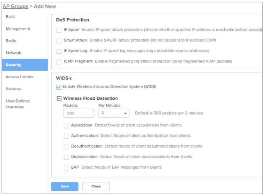
- In the Wireless Flood Detection section, configure the number of packets and duration from the Packets and Per Minutes drop-down lists.
This indicates the number of flood attack packets that cnMaestro must detect in the specified to identify and report the type of attack.
- Select the type of flood attack detection types that you want to configure in the Wireless Flood Detection section.
Table 51 Wireless Flood Detection parameters
| Field Description | |
| Association Detect floods of client associations from clients. | |
| Authentication Detect floods of client authentication from clients. | |
| Deauthentication Detect floods of client deauthentications from clients. | |
| Disassociation Detect floods of client disassociations from clients. | |
| EAP Detect floods of EAP messages from clients. | |
Wireless Intrusion Prevention System (WIPS)
WIPS is a critical feature within cnMaestro designed to enhance the security of wireless networks. ' enabled, WIPS triggers Wi-Fi devices to deauthenticate rogue APs and clients by sending spoofed
deauthentication messages to the rogue APs and clients. You can also trigger Wi-Fi devices to deauthenticate honeypot APs and clients by enabling this feature.
CLI configuration:
To configure AP to detect honeypot and rogue APs, and send deauth requests to respective connect clients:
ap(config)# wips
deauth-honeypot-clients : Detect honeypot APs and send deauth to respective clients
deauth-rogue-ap-clients : Detect rogue APs and send deauth to respective clients
Configuring Services
This chapter describes the following topics:
Overview
- Configuring services
Overview
This chapter gives an overview of Enterprise Wi-Fi AP configurable parameters related to User Group Location API, Speed Test, BT Location API, Bonjour Gateway, LACP, and RTLS.
Configuring services
This section provides information on how to configure the following services on Enterprise Wi-Fi AP.
To configure the services for the AP, complete the following steps:
- Navigate to Configuration > Wi-Fi Profiles > AP Groups page.
- Click Add New and select Enterprise Wi-Fi (E-Series, XE/XV/X7-Series) from the Type drop-down list.
- Click Services tab and configure the following services:
• Lightweight Directory Access Protocol (LDAP)
- NAT Logging
- User Groups
- Wi-Fi API
- Bluetooth API
- Speed Test
- DHCP Option 82
- Bonjour Gateway
- Link Aggregation Control Protocol (LACP)
• Real-Time Location System (RTLS)
Lightweight Directory Access Protocol (LDAP)
The following table lists the fields that are displayed in the AP Groups > Services > Network > LDAP page.
Table 52 LDAP parameters
| Parameters | Description Range Default | ||
| Server Host | IP address or hostname of the LDAP server. | AP server. | - - |
| Server Port | Port number of the LDAP server. | - | - |
Figure 64 LDAP parameters

NAT Logging
NAT logging is same as the internet access log that is generated when NAT is enabled on AP. access log PDU consists of one or more internet access log data in TLV format. The packet for internet access log PDU is defined as below:
Table 53 PDU type code: 0x82
| Type | Mandatory Length | Default Value |
| 0x01 N 32 Bytes | Includes | IPv4 internet access log data structure. |
Type 0x01 TLV includes the internet access log data structure as below:
Table 54 NAT Logging packet structure
| Length | Description |
| 4 Bytes | NAT records UNIX time stamp which generates time in seconds from 1970-01-01 (00:00:0 GMT until now). |
| 6 Bytes | The MAC address of the client. |
| 1 Bytes | Reserved for future use. |
| 1 Bytes | The protocol type. The supported protocol types are:0x06 TCP0x11 UDP |
| 2 Bytes | The VLAN ID where the client is connected. If there is no VLAN ID, the value will be |
| 4 Bytes | The client internal or the private IP address. |
| 2 Bytes | The internal port of the client. |
| Length | Description |
| 4 Bytes | The Internet IP address which is translated by NAT. |
| 2 Bytes | The Internet port which is translated by NAT. |
| 4 Bytes | The IP address of the visited server. |
| 2 Bytes | The port address of the visited server. |
Below table lists the fields that are displayed in AP Groups > Services > Network > NAT Logging page.
Table 55 NAT Logging parameters
| Parameters | Description Range Default | ||
| Enable Provision to enable/disable NAT logging services. - - | |||
| Server IP Provision to configure IP/Hostname of NAT logging server. | - - | ||
| Server Port Provision to configure custom port number for NAT Logging services. | - | ||
| Interval Provision to configure frequency of logging. | 5-3600 | 5 | |
Figure 65 NAT Logging parameters
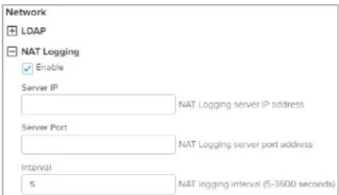
User Groups Premium feature
Some policies, like VLAN, require many RADIUS attributes to be sent by the RADIUS server and by the AP. Some wireless network administrators do not have administrative access to the RADIUS so making changes to wireless policies would require waiting for the RADIUS administrator to make changes.
To simplify wireless administration and streamline changes, a feature called User Groups is provided allows the wireless administrator to apply a set of wireless policies to a user based on a single attribute. This eliminates the need for administrative rights on the RADIUS server and simplifies applying complex policies to end-user stations.
A user group can also be assigned to a station based on the device type. This approach is de accuracy and completeness of device identification functionality, which is not guaranteed to be accurate exhaustive.
The User Group feature is natively supported by XMS Cloud.
Figure 66 User Groups interaction
User Groups Interaction

flowchart
graph TD
    A["Client Station"] -->|associate and authenticate| B["AP"]
    B -->|validate credentials| C["RADIUS Server"]
    C -->|send Access-Accept with user group attribute| B
    B -->|Allow access and apply policies| D["Look up user group by radius-id"]
CLI Configuration:
ap(config)# group
Specify user group number <1-16>
ap(config)# group 1
ap(config-group-1)#
clear : Clear command
filter-list : Filter list selection for this user group
radius-id : Radius Filter-ID (Attribute Type 11) mapped to this user group
shutdown : Disable the user group
vlan : Set the vlan id for client traffic on this user group
apply : Apply configuration that has just been set
exit : Exit from user group configuration
no : Disable user group parameters
save : Save configuration to Flash so it persists across reboots
show : Show command
ap(config-group-1)#
Example:

User group properties and actions
A user group supports the following properties and actions:
| Command Description | |
| shutdown Disable this User Group | |
| radius-id Radius Filter-ID (Attribute Type 11) mapped to this User Group | |
| no shutdown Enable this User Group | |
| no groupDelete User Group | |
User group policies
The policies available in a user group configuration are a subset of those for an SSID. The most used policies are filter-list and VLAN.
| Policy Description | |
| filter-listFilter List | setting for this User Group |
| vlan VLAN associated with | this User Group |
Real-Time Location System (RTLS)
RTLS is a method to send the discovered (probed) clients list to a specified server address. The sent as HTTP Post to the HTTP server every interval. The discovered client entries are deleted from the entry is aged out. The client aging timeout is 2 times of location API interval configured. If new probe requests from the client within 2 x location API interval time, then the client entry will from the list.
The following RTLS systems are available:
- Wi-Fi API
- Bluetooth API
Wi-Fi API
Below table lists the fields that are displayed in the AP Groups > Services Network > RTLS (Real-Time Location System) > Wi-Fi API page.
Table 56 Wi-Fi API parameters
| Parameters Description Range Default | |||
| Enable Provision | to enable or disable Wi-Fi API services. - - | ||
| Server URL Provision | to configure HTTP or HTTPS server to send with the port number. | a- report | - |
| Interval Provision | to configure the custom frequency of information to be shared on server. | 2-3600 | 5 |
| Ignore Anonymized MACs | Avoid populating locally administrated MAC addresses Wi-Fi API client list. | - in the | - |
Figure 67 Wi-Fi API parameters
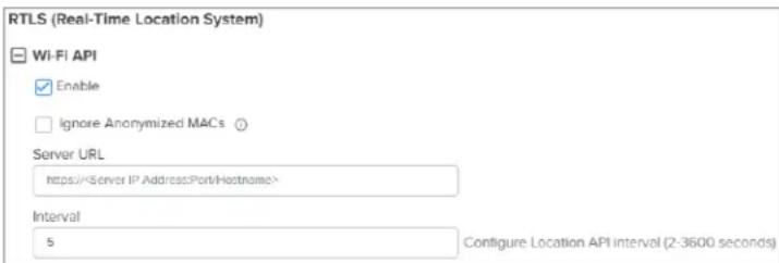

Note
For further details about this feature and sample reference output, go to https://support.cambiumnetworks.com/files/cnpilot-tech-ref/ and download Wireless client Presence and Locationing API document.
Bluetooth API
XV3-8/XV2-2T APs with an integrated Bluetooth Low Energy (BLE) radio can detect and locate near devices. This data is then provided via API to third-party applications. Examples of such devices include smartwatches, battery-based beacons, Apple iBeacons, fitness monitors, and remote sensors.
Organizations can create use cases for indoor wayfinding and mapping, asset tracking, and more.
Below table lists the fields that are displayed in the AP Groups > Services Network > RTLS (Real-Time Location System) > Bluetooth API page..
Figure 68 Bluetooth API

Table 57 Bluetooth API parameters
| Parameters Description Range Default | |||
| Enable Enable or disable Bluetooth API services. - - | |||
| Server URL and Port | Configure HTTP or HTTPS server and the port number, to a report. | per, to | send |
| Interval Configure | the custom frequency of information to be shared server. | 28600 | 5 |
Sending report
After enabling BLE Scanning on AP it will start processing:
- Convert the scanned data to a JSON array.
- Send that data in one single HTTP/HTTPS POST.
To configure the BT Location-API in the CLI:
ap(config)# location-api
ignore-anonymized-mac : Ignore MAC addresses that are anonymized
interval : Configure reporting interval in secs
server : HTTP/HTTPS server to send report to with the port number
To disable the BT Location-API:
ap(config)# no location-bt-api
Bluetooth API data elements
Table 58 Bluetooth API data elements
| Parameters Description | |
| apMac MAC address of the | observing AP. |
| API Version API Version applied for particular data format. | |
| AP Name Host name of the observing AP. | |
| Timestamp Observation time | in seconds seen by AP. |
| BT MAC BLE device MAC | seen by AP. |
| UUID BLE device UUID seen by AP. | |
| RSSI BLE device RSSI as seen by AP. | |
HTTP POST body format:
{
    u'ap_mac': '00-04-56-A5-5A-EC',
    'version': '2.2',
    'ap_name': 'X7-35X-B0007C',
    'ap_name': 'XV3-8-EC7708',
    'ble_discoverd_clients': {Array of 0-250 devices}
}

Bluetooth API Data Format
{
    bt_rssi': u' -80 dBm ',
    bt_mac': 14-8F-21-FD-37-18', u
    'bt_uuids': Garmin International, Inc. (0xfelf)\n',
    'bt_timestamp': u' 1.811127'
}
Stanley AeroScout Premium feature
The Location Engine delivers accurate and reliable location data for assets and customers with STAN Healthcare Wi-Fi tags. It is an integral component of STANLEY Healthcare's AeroScout RTLS solutions AeroScout Location Engine determines location using signal strength measurements (RSSI) collected by Cambium Wi-Fi Access Points, that can simultaneously serve location sensors and provide network ac AeroScout utilizes a location engine to determine the position of Wi-Fi tags.
CLI Configuration:
ap(config)# rtls aeroscout
ble-tag : Enable Aeroscout BLE Tag
server : Configure Aeroscout Server IP or FQDN
server-port : Configure Aeroscout Server Port (Default port:12092)
wifi-tag : Enable Aeroscout WiFi Tag
Below table lists the fields that are displayed in the AP Groups > Services Network > RTLS (Real-Time Location System) > Stanley AeroScout page..
Figure 69 Stanley AeroScout
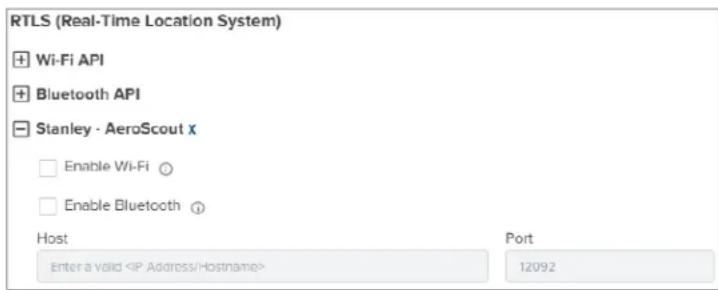
Table 59 Stanley AeroScout parameters
| Parameters Description Range Default | |||
| Enable Wi-Fi Enable or disable Wi-Fi or Bluetooth Stanley Aero services. Enable Bluetooth | Enable or disable Wi-Fi or Bluetooth Stanley Aero Services. | Scout | - |
| Server URL and Port | Configure HTTP or HTTPS server and the port number send a report. | Port: 12092 | |
Speed Test
Wi-Fiperf is a speed test service available on Enterprise Wi-Fi AP devices. This tool is interoperable open source zapwireless tool (https://code.google.com/archive/p/zapwireless/).
The Wi-Fiperf speed test can be triggered by using zapwireless tool between two Enterprise Wi-Fi between Enterprise Wi-Fi APs and other third-party devices (or PC) that is having zapwireless endpo running.
Refer to https://code.google.com/archive/p/zapwireless/ to download the zap wireless tool to generate zapwireless endpoint for third party device (or PC) and zap CLI to perform the test.
In this case, Wi-Fiperf endpoint should be enabled in Enterprise Wi-Fi AP through UI shown below.
To configure the above parameter, navigate to the AP Groups > Services > Network > Speed Test page.
Select the Wi-Fiperf checkbox to enable the speed test.
Figure 70 Speed Test parameters

Speed Test
□ Wi-Fiperf Enable Wi-Fiperf Endpoint
DHCP Option-82
DHCP Option 82 parameter enabled at the device level with VLAN IDs inserts the Option 82 paran all the DHCP client packets leaving the configured VLAN interfaces. This device-level configuration precedes the DHCP Option 82 configuration at the WLAN profile or the L3 interface levels.
In case DHCP Option 82 is configured at the device-, WLAN profile-, and L3 interface-levels, the fo priority order is considered:
- Device-level configuration
- WLAN profile-level configuration
- L3 interface-level configuration
The device-level configuration is recommended when it is desired to insert the DHCP Option 82 for following options:
- Guest access enabled wired traffic
- Guest and without guest access enabled wireless DHCP client traffic
To configure the above parameter, navigate to the AP Groups > Services > Network page and provide the details in the DHCP Option 82 section:
-
Select the Enable checkbox.
-
Select the circuit ID from the Option 82 Circuit ID drop-down list.
Following are the supported values:
- None
• All - Hostname
- APMAC
- SSID
• VLANID - SITEID
-
Custom
-
Select the remote ID from the Option 82 Remote ID drop-down list.
Following are the supported values:
- None
- Hostname
- APMAC
- SSID
• VLANID - SITEID
-
Custom
-
Enter the VLAN ID in the VLAN ID text box.
- Click Save.
Figure 71 DHCP Option 82 parameter

Bonjour Gateway
Bonjour enables the automatic discovery of devices such as printers, file servers, and other clients. Services on a local network. Bonjour Gateway feature on Wi-Fi AP extends the scope of Bonjour: beyond the local network by forwarding Bonjour Multicast DNS (mDNS) packet across different VLANs make Bonjour services and devices available between the different wireless and local networks.
Below table lists the fields that are displayed in the AP Groups > Services > Bonjour page.
| Parameters Description | Range Default | ||
| Enable Bonjour Gateway | Provision to enable or disable Bonjour Gateway services. | - | - |
| Service Name Provision for user-defined Bonjour rule name. | - | - | |
| Proto Select the required mDNS protocol. | - | - | |
| From VLAN VLAN | in which mDNS/Bonjour service is running. | - | - |
| To VLAN VLAN in | which clients are listening. | - | - |
CLI Configuration:
- Enable Bonjour Gateway on AP.
- To control mDNS repeated packet to WAN side.
ap(config)# bonjour-fw bonjour-forward-to-wan
all : Forward all bonjour mdns packets queries and response repeated with vlan to WAN side
queries : Forward bonjour mdns Query packets repeated with vlan to WAN side
responses : Forward bonjour mdns Response packets repeated with vlan to WAN side
Note
-
By default, mDNS repeated will not send to the WAN side.
-
WAN side indicates Eth 1 interface, Mesh client interface in case of mesh client mc tunnel interfaces like L2GRE, and L2TP.
Link Aggregation Control Protocol (LACP)
LACP provides the ability to group multiple physical ports as a logical port. This logical port is re port-channel and supported only on XV3-8 devices. LACP is a dynamic protocol used to form and the Link aggregation between two LACP supported devices.
LACP provides the following benefits:
- Increased Bandwidth: traffic may be balanced across the member ports to provide increased agg throughput.
- Link redundancy: the LACP bundle can survive the loss of one or more member links.
Configuration:
To add Ethernet to port channels:
ap(config)# interface portchannel 1
ap(config-portchannel-1)# exit
ap(config)# interface eth 1
ap(config-eth-1)# channel-group 1
ap(config-eth-1)# exit
ap(config)# interface eth 2
ap(config-eth-2)# channel-group 1
ap(config-eth-2)#
Port-channel configuration:
ap(config)# interface portchannel 1
ap(config-portchannel-1)#
advertise : Ethernet link speed advertisement
channel-group : Ethernet member channel group
clear : Clear command
duplex : Ethernet link duplex
shutdown : Shutdown interface
speed : Ethernet link speed
switchport : Configure switch port
tunnel-mode : Enable tunnelling of wired traffic over configured tunnel
apply : Apply configuration that has just been set
exit : Exit from interface configuration
no : Disable parameters
save : Save configuration to Flash so it persists across reboots
show : Show command
Syntax:
ap(config)# interface portchannel 1
ap(config-portchannel-1)# switchport mode trunk
ap(config-portchannel-1)# switchport trunk allowed vlan 1
ap(config-portchannel-1)# switchport trunk native vlan 1
ap(config-portchannel-1)#
Operations
This chapter describes the following topics:
- Overview
- Firmware upgrade
Overview
This chapter gives an overview of Enterprise Wi-Fi AP administrative functionalities, such as firmware update, System, and Configuration.
Firmware upgrade
The running software on the Cambium Enterprise Wi-Fi AP can be upgraded to newer firmware. Wi upgrading from the UI, the user can upload the firmware file from the browser. The same process followed to downgrade the AP to a previous firmware version if required. Configuration is maintained the firmware upgrade process.

Note
Once a firmware upgrade has been initiated, you must not restart the AP or power cycle until the process completes, as this might leave the AP inoperable.
To initiate a firmware update on the AP, complete the following steps:
- Navigate to Monitor and Manage > System > Software Update.
- Select Enterprise Wi-Fi (XE/XV/X7-Series) from the Device Type drop-down list.
- Select the appropriate firmware version from the Versions drop-down list.
- From the list of devices, select the devices for which you want to update the firmware.
- Select the time when you want to perform the update from the Update section.
- Select the appropriate options from the Job Options section.
- If you select multiple devices, specify how many devices must be updated simultaneously in the box.
A maximum of 500 devices can be updated simultaneously.
- Click Add Software Job to
devices.
Figure 74 Software update

LED Test flashing pattern
The LED test flashing pattern for the Enterprise Wi-Fi AP is as follows:
Flashing pattern (For X7-35X, XV3-8, XV2-2, XV2-2T0, XV2-2T1, XE5-8, and XE3-4): Yellow -> Green -> Amber -> Blue
Flashing pattern (For XV2-21X, XV2-23T, and XV2-22H): Green -> Amber -> Blue
CLI commands:
ap(config)# service flash-leds
Number of seconds to flash <1-120> (optional: default 10sec)
ap(config)# service test leds
Troubleshoot
This chapter provides detailed information about troubleshooting methods supported by Enterprise Wi-Fi APs. Troubleshooting methods supported by Enterprise Wi-Fi AP devices are categorized as below:
- Status
- Downloading tech support file
- Logging
Debug Logs
• Radio Frequency (RF)
Wi-Fi Analyzer - Packet capture
- Performance
Network Connectivity - Remote CLI
- Flash LEDs
• XIRCON tool support - XIRCON tool support for Linux 1.0.0.40
Status
The Status page displays the status of link between the Enterprise Wi-Fi AP and clients. It also displays mesh connections present. You can download the tech support file for further troubleshooting from a page.
To view the status of the link between the Enterprise Wi-Fi AP and clients, access the Status page under Monitor and Manage >
Figure 75 Status page

Downloading tech support file
To download the tech support file, click the Download Tech Support File ( ) icon on the Status page.
Figure 76 Downloading tech support file

Logging
Enterprise Wi-Fi AP devices support multi-level logging, which will ease debug issues.
Debug Logs
Enterprise Wi-Fi AP provisions enhanced debugging of each module as events generated by system scope of debugging is limited. Debug logs are triggered when the user clicks Start Logs and terminates when user clicks Stop Logs. By default, debug logs auto terminate after 1 minute after initiating.
The Debug page displays log information of the Enterprise Wi-Fi AP. To view the debug information complete the following steps:
-
Navigate to the Monitor and Manage >
> Tools > Debug tab. -
Click Start Logs.
The log information is displayed in the Output window.
Figure 77 Debug page
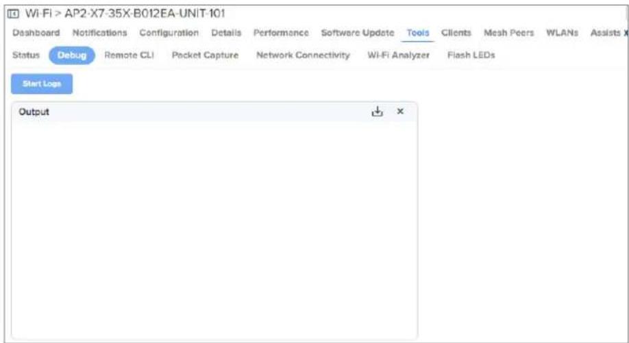
Radio Frequency (RF)
Wi-Fi Analyzer
Wi-Fi Analyzer enables customers to scan the supported channels as per regulatory domain and pro information related to AP's presence in each channel. Wi-Fi analyzer graphs are available in two m
- Interference
This tool shares more information about each channel as below:
Noise
- Interference measured in RSSI
- List of neighbor APs
• Number of APs
This tool shares more information about each channel as below:
- Noise
• Number of neighbor APs
• List of neighbor APs
To view the channel information, complete the following steps:
- Navigate to the Monitor and Manage >
> Tools > Wi-Fi Analyzer tab. - Select the radio band for which you want to view the information.
The following options are supported:
• 2.4 GHz
- 5 GHz
• 6 GHz (displayed only for supported APs)
3. Click Start Scan.
The channel information is displayed as follows:
• Interference display mode
Figure 78 Interference display mode

line
| Channel | Interference | Noise | |---------|--------------|-------| | 26 | -20 | -60 | | 42 | -18 | -60 | | 44 | -25 | -60 | | 52 | -60 | -60 | | 50 | -40 | -60 | | 60 | -55 | -60 | | 94 | -20 | -60 | | 115 | -55 | -60 | | 128 | -30 | -60 | | 161 | -50 | -60 | | 106 | -10 | -60 |• Number of APs display mode
Figure 79 Number of APs display mode

Packet capture
Allows the administrator to capture packets from the APs UI, cnMaestro UI, or XMS-Cloud. The adn can filter the packets being captured by specifying a particular MAC address, IP address, and port. The user can trigger packet capture on one or more interfaces, simultaneously view the progress of capture. The user can also download the captured pcap file on completion.
Enterprise Wi-Fi AP device allows packet capture on the following interfaces:
- Ethernet
- Radio
- Wireless LAN
• VLAN - SSID
- Tunnel
- Bridge
- PPPoE

Note
When AP packet capture is configured for the radio or wireless LAN interface, the AP records data only from the nearby APs. It does not capture its own transmissions like beacon frames or SSID broadcasts.
Multiple options of filtering are provided and are available at Troubleshoot > Packet Capture page.
To generate and view the packet information, complete the following steps:
- Navigate to the Monitor and Manage >
> Tools > Packet Capture tab.
Figure 80 Packet Capture page

- Click New Packet Capture.
The New Packet Capture window is displayed.
Figure 81 New Packet Capture window
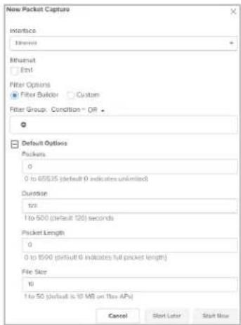
-
Configure the required interface and the corresponding parameters, and the filter options.
-
Click Start Now or Start Later depending on whether you want to start packet capture now or at a later time.
When you select Start Later, you must click the start ( ) icon to start the packet capture.
- After the capture starts, the Status column displays Running.
Click the stop ( ) icon to stop the capture.
-
To download the packet capture file, click the download ( ) icon.
-
To replicate an existing packet capture with different filter options, click the clone ( ) icon corresponding to the packet capture. Specify the filter options and click Clone.
Figure 82 Clone packet capture

Performance
Network Connectivity
This tool helps to check the accessibility of remote hosts from Enterprise Wi-Fi AP devices. The tools are supported:
- Ping / Ping6
• DNS Lookup / DNS Lookup6 - Traceroute
To test network connectivity of the router, complete the following steps:
- Navigate to the Monitor and Manage >
> Tools > Network Connectivity tab. - Select the required test type from the Test Type dropdown list and configure the corresponding parameters required for the test as described in the following table:
Table 61 Troubleshoot: Connectivity
| Parameters Description Range Default | |||
| Ping / Ping6 | |||
| IP Address or Hostname | IPv4 address or hostname to validate the reachability of destined Host. | bility of | the |
| Number of Packets | Number of request packets that are required to transmitted to validate the reachability of the destined Host. | 1-10 3 | |
| Buffer Size ICMP packet size to be transmitted. 1-65507 56 | |||
| Ping Result Displays the ICMP results. - - | |||
| DNS Lookup / DNS Lookup6 | |||
| Host Name Hostname whose IP must be resolved. - - | |||
| DNS Test Result Displays the IPs that are associated with configured hostname. | - | ||
| Traceroute | |||
| IP Address or Hostname | IPv4 address or hostname to validate the reachability of destined Host. | bility of | the |
| Fragmentation Indicates whether to allow or deny fragment packets. - Off | |||
| Trace Method | Payload mechanism to check the reachability of desired IPv4 address of hostname. | - deGMP | Echo |
| Display TTL | Provision to customize TTL display. | - | On |
| Verbose | Provision to display the output of traceroute. | - On | |
| Traceroute Result | Displays the output of the traceroute command. | - - | |
3. Click Start .
cnMaestro initiates the test and displays the result in the
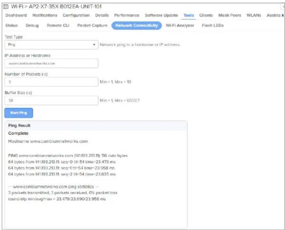
Remote CLI
This tool allows users to execute device CLI commands, such as service show and show through cnMaestro.
To execute CLI commands, complete the following steps:
- Navigate to the Monitor and Manage >
> Tools > Remote CLI tab. - Enter the command in the Command box.
- Click Run.
The command output is displayed in the Output window.
Figure 83 Remote CLI page
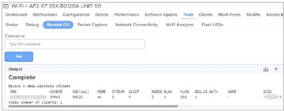
- To download the output, click the download ( ) icon.
Flash LEDs
Flash LEDs indicate that a device is ready to receive the signal.
To flash the LEDs of an AP, access the Flash LEDs page under Monitor and Manage >
Figure 84 Flash LEDs page
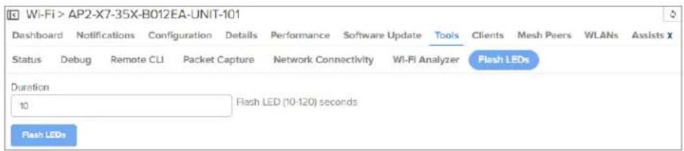
XIRCON tool support
The Xirrus console (Xircon) is a necessary tool for daily management, troubleshooting, and testing. X customers and field engineers use them for initial configuration, troubleshooting individual AP problems changing IP addresses, and recovering units that would not boot. Since Cambium Networks acquired and we expect the XV series APs to be deployed along with legacy Xirrus APs, limited Xircon's added to the XV series APs.
The name "Xircon" refers to the feature in general, including the AP functionality, the communication protocol, and the client software used for discovering and controlling Xirrus APs.
- Xircon detects APs by listening for Xircon beacon packets. These packets are sent via UDP to port and multicast address. These are the existing Multicast beacons sent by AOS.
-
Control is established over unicast UDP on a different port from discovery. Only one client dev control an AP at any given time.
-
Individual packets are RC4 encrypted. The payload includes a hash to ensure that any tamperin packet corruption is detected, and the packet discarded.
- Starting with Release 6.2, Enterprise Wi-Fi APs can be detected by Xirrus AOS APs and the client. It is not possible to establish a Xircon console connection to XV series APs – for that IP address from Xircon and use standard SSH to connect.
XIRCON tool support for Linux 1.0.0.40
XIRCON tool support for Linux 1.0.0.40 has been added which is used to discover APs in the next IP address is not known.
Management Access
This chapter describes different methods of authenticating users to access device UI. Following are authentication methods supported by Enterprise Wi-Fi AP devices:
- Local authentication
- SSH Key authentication
• RADIUS authentication
Local authentication
This is the default authentication mode enabled on the device. Only one username is supported w admin. The default password for the admin username is admin. The user has a provision to configure or update password.
Device configuration
The below figure shows how to configure or update the default password of the admin user.
- Navigate to AP Groups > Management section.
- Enter the administrator password in the Admin Password field.
- Click Save.
Figure 85 Configure/update default password of the admin user

SSH Key authentication
SSH keys are also used to connect remote machines securely. They are based on the SSH crypto network protocol, which is responsible for the encryption of the information stream between two ma Ultimately, using SSH keys users can connect to remote devices without even entering a password much more securely too. SSH works based on “public-key cryptography”. For simplicity, let us consider SSH keys come in pairs. There is a private key, that is safely stored to the home machine of the a public key, which is stored to any remote machine (AP) the user wants to connect. So, whenever initiates an SSH connection with a remote machine, SSH first checks if the user has a private key matches any of the public keys in the remote machine and if not, it prompts the user for a pa
Device configuration
SSH Key-based access method can be configured on the device from cnMaestro. Navigate to AP Groups > Management section and complete the following steps.
-
Select the SSH checkbox.
-
Provide the public key generated from the steps described in the SSH Key generation section.
Figure 86 Management parameters

SSH Key generation
Windows
You may use a tool, such as PUTTY to generate both public and private keys. Below is a sample demonstration of configuring Enterprise Wi-Fi AP device and logging using SSH key via UI.
- Generate a key pair in PUTTY Key Generator as shown in .
Figure 87 Generating public/private Key

- Save the Public key and Private key once the key pair is generated as shown in .
Figure 88 Public and Private Key

- Save the Public key generated in the step above as described in Device configuration section.
- Login to device using private key generated above with username as admin.
Linux
If using a Linux PC and SSH from the Linux host, then you can generate the keys with the fo
- Generate key pair executing below command on Linux console as shown in Figure 89.
Figure 89 Public Key location path
pk@ubuntu:~$ ssh-keygen -t rsa
Generating public/private rsa key pair.
Enter file in which to save the key (/home/pk/.ssh/id_rsa):
Created directory '/home/pk/.ssh'.
Enter passphrase (empty for no passphrase):
Enter same passphrase again:
Your identification has been saved in /home/pk/.ssh/id_rsa.
Your public key has been saved in /home/pk/.ssh/id_rsa.pub.
The key fingerprint is:
SHA256:0qt4vJduO4uvpdptPkNzQ9uor1H7ydwE9fiEXOh0Kao pk@ubuntu
The key's randomart image is:
+----[RSA 2048]----
|    |
|    ..|
|    .+.o|
|    . ..=.* |
|    . S..=. = o|
|    .oo*... o |
|    ..+E.. . |
| oo*X. + +
| ooBXOO. = .
+----[SHA256]----
pk@ubuntu:~$
- The public key is now located in PATH as mentioned in Figure 89.
PATH = "Enter the file to which to save the key"
- The private key (identification) is now saved in PATH as mentioned in Figure 90.
PATH = "Your identification has saved in <>"
Figure 90 Private Key saved path
pk@ubuntu:~$ cat /home/pk/.ssh/id_rsa.pub
ssh-rsa AAAAB3NzaClyc2EAAAADAQABAAABAQDfZq+gc13qG8DlckyfU2JqyW5pI9q8P0MrVtrM9Vu5P851kbIiCtsTmPm6Ewrfq/nhWWsn6k4p20pTZ/laX/Ww9BWf4jjw8nOqNY95zlJUD9mV48gqrOY8qbXv5gybXLZ+A0LarSgDaeoasM34xiJEqL+/GWkJW9/ckyueliSwAeX8ki++zJeIOQZrJWcJ6mlYHZfd4Yyb1LRg78L+q4YbHZAdkooUkTNXJ0kaBwR2i3OJjHxD1D+SRE3DrP9xAAD11cB5MvgQNWeBJ4ale4rwkphPQetH/lisY/DI9nkr8Hwul2JEDeMq5yII7Fdh6ALJb+b2mtZnbGBxdsM4HrTt pk@ubuntu
pk@ubuntu:~$
pk@ubuntu:~$
-
Save the public key generated in step above as described in the Device configuration section.
-
Login to device using private key generated above with username as admin.
RADIUS authentication
Device management access using RADIUS authentication allows multiple users to access using unique credentials and is secured.
Device configuration
Management access using the RADIUS authentication method can be configured on the device from cnMaestro. Navigate to AP Groups > Management and configure the following:
-
Select the RADIUS Mgmt Authentication check box.
-
Configure RADIUS IPv4/Hostname and shared secret in the RADIUS Server and RADIUS Secret parameters respectively.
-
Click Save.
Figure 91 RADIUS Server and RADIUS Secret parameters

Mesh
From Release 6.4 onwards, Enterprise Wi-Fi Access Points support mesh connections between radios. suggested maximum hops are two. Mesh links can form between radios of the same band of open GHz, 5 GHz, and 6 GHz), but the two peers of the mesh link do not have to be of the same example, a link between Wi-Fi 6 XV2-21X and XV2-23T is supported. Given the larger set of available channels and typically cleaner RF environment, Cambium Networks recommends using the 6 GHz rad mesh backhaul if the AP is 6 GHz-capable, else use the 5 GHz band.
A mesh link can be created between two radios by configuring one of them as a Base and the Client on the first WLAN of the AP. Typically, the wired connectivity AP would be configured as (MB). The radio setup for the MB selects a channel and starts transmitting beacons as soon as t up. The Mesh Client (MC) radio setup scans all available channels, looking for an MB radio to cc The SSID in the mesh WLAN is how the client and base radios of a mesh link identify each c SSID should be configured on the MB WLAN as well as the MC WLAN.
In addition to a simple topology between a base and a client, a star or hub-and-spoke mesh top supported; practically a mesh radio can service up to 10-12 Mesh Clients connected to it. When a configured with a mesh WLAN, on that WLAN other clients are allowed to connect, and the radio clients on other WLANs mapped to it. Note that a client radio starts rescanning all available channels as it loses connectivity to the base. Other WLANs mapped to it are not operational during this s
The mesh link can also be secured with WPA2/WPA3-Preshared-Keys (PSK). The same passphrase sh be configured on both the MB as well as the MC. Standard 802.11 security handshakes and AES-0 encryption are then used on the mesh link.
For WPA2-PSK, the maximum number of allowed characters is 64 whereas for WPA3-PSK, it is 63.
Deployment scenarios
Enterprise Wi-Fi APs support single and multi-hop mesh connections, although single hop mesh is hi advisable.
Enterprise Wi-Fi APs support the following deployment scenarios:
- Between Cambium APs
- With third-party APs, such as TP-Link, MikroTik, and LigoWave
Enterprise Wi-Fi APs support the following deployment scenarios:
- Between Wi-Fi 6 APs
- Mixed deployment (between Wi-Fi 6 APs and Wi-Fi 5 APs)
- With third-party APs - TP-Link, MikroTik, and LigoWave
The following figures illustrate the working scenario of a wireless mesh network.
Figure 92 Single hop mesh connection in 5 GHz with two Mesh Clients

flowchart
graph TD
    A["Client Connection"] -->|2.4 GHz| B["Mobile Device"]
    A -->|5 GHz| C["Mobile Device"]
    B -->|5 GHz| D["Client Connection"]
    C -->|2.4 GHz| D
    C -->|5 GHz| E["Mobile Device"]
    D -->|2.4 GHz| E
    style A fill:#f9f,stroke:#333
    style B fill:#ccf,stroke:#333
    style C fill:#cfc,stroke:#333
    style D fill:#fcc,stroke:#333
    style E fill:#cff,stroke:#333
Figure 93 Single hop mesh connection in 5 GHz with two Mesh Clients and 2.4 GHz and 5 GHz as access

flowchart
graph TD
    A["Mobile Device"] -->|2.4 GHz| B["Client Connection"]
    A -->|5 GHz| C["Mobile Device"]
    B -->|5 GHz| D["Client Connection"]
    B -->|5 GHz| E["Mobile Device"]
    C -->|2.4 GHz| F["Client Connection"]
    C -->|5 GHz| G["Mobile Device"]
    D -->|5 GHz| H["Mobile Device"]
    E -->|2.4 GHz| I["Mobile Device"]
    E -->|5 GHz| J["Mobile Device"]
Figure 94 Single hop mesh Connection in 6 GHz with two Mesh Clients
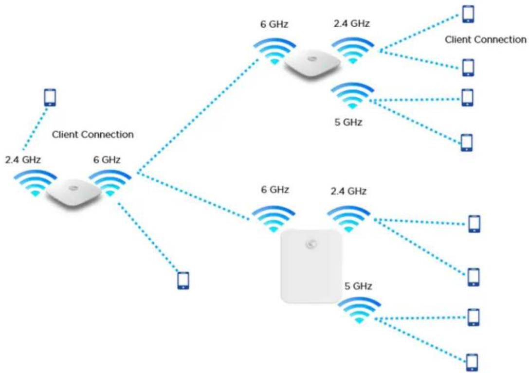
flowchart
graph TD
    A["Mobile Device"] -->|2.4 GHz| B["Client Connection"]
    A -->|6 GHz| C["Mobile Device"]
    B -->|6 GHz| D["Mobile Device"]
    B -->|2.4 GHz| E["Client Connection"]
    C -->|5 GHz| F["Mobile Device"]
    C -->|6 GHz| G["Mobile Device"]
    D -->|2.4 GHz| H["Mobile Device"]
    E -->|5 GHz| I["Mobile Device"]
    F -->|2.4 GHz| J["Mobile Device"]
    G -->|5 GHz| K["Mobile Device"]
    style A fill:#f9f,stroke:#333
    style B fill:#ccf,stroke:#333
    style C fill:#cfc,stroke:#333
    style D fill:#fcc,stroke:#333
    style E fill:#cff,stroke:#333
    style F fill:#ffc,stroke:#333
    style G fill:#cfc,stroke:#333
    style H fill:#fcc,stroke:#333
    style I fill:#ffc,stroke:#333
    style J fill:#fcc,stroke:#333
    style K fill:#ffc,stroke:#333
For a stable mesh link to be established, Enterprise Wi-Fi mesh is configurable in the following th
- Mesh Base (MB)
Enterprise Wi-Fi device that operates in MB mode is the key to Mesh topology. MB is usually to the wired network. The radio setup for MB selects a channel and starts transmitting beacon as the AP comes up.
- Mesh Client (MC)
Enterprise Wi-Fi device that operates in MC mode, scans all available channels supported as per regulatory domain and establishes a link with MB.
- Mesh Recovery (MR)
When enabled, this mode helps maintain the mesh link if there is a disruption in the backhaul established with MB and MC. Mesh link disruption can cause due to PSK mismatch or due to asynchronous configurations on MB and MC. This mode needs to be exclusively enabled on ME devices.
This mode can also help in the Zero Touch Configuration of the Enterprise Wi-Fi device.
Mesh configurable parameters
The below table lists the configurable parameters that are exclusive to mesh:
Table 62 Mesh configurable parameters
| Parameter | Description Range Default | ||
| Mesh This | parameter is required when a mesh connection is established with Enterprise Wi-Fi devices. Four options are available under parameter:1. Base: A WLAN profile configured with a Mesh Base operates like a normal AP. Its radio beacon is on startup so its SSID can be seen by radios configured as Mesh Clients.2. Client: A WLAN profile configured with a Mesh Client scans all available channels on startup, looking for a mesh-based AP to connect.3. Recovery: A WLAN profile configured as mesh-recovery broadcast pre-configured SSID upon detection of mesh link failure after a successful connection. This needs to be exclusively configured on the mesh-base device. Mesh Client auto-scan for mesh-recovery SSID upon failure of mesh link. | this | |
| SSID SSID | is the unique network name to which MC connects and establishes mesh links. | - | |
| VLAN Management | VLAN to access all devices in a mesh topology. 1-4094 1 | ||
| Security For | configurable parameters, refer to Chapter 6: Security section. - | Open | |
| Passphrase | A string that is a key value to generate keys based method configured. | -on12345678 | |
| Radios Each | SSID can be configured to be transmitted as per the 2.4 GHz deployment requirement. For a mesh WLAN profile, options available to configure the band:• 2.4 GHz• 5 GHz• 6 GHz | ||
| Hide SSID | This is the basic security mode of a Wi-Fi device. when enabled, will not broadcast SSID. | ThisDisplacetheter | |
| SNR-threshold | Mesh Clients trigger a disconnect when SNR is below value. This is the applicable configuration on the MB. | 1-4094678Disabled | |
| Mesh Recovery Interval | Configure the interval for the consecutive ping loss se which the mesh link is considered to be down and attempted. One can configure the duration and interval same, in which case the first ping losses trigger the | 5-30after mirreconnect is to be reconnect. | 30 |
| Mesh Auto Detect Backhaul | 1. Single HopBoth Mesh Client and MB profiles are configured on the devices. When enabled, this feature triggers when an MB losses Ethernet connectivity. Mesh Client profile automatically gets enabled and establishes a mesh link with the nearest MB. For the MB profile to get auto-disabled, uncheck Mesh Multi-Hop.2. Multi-HopConsider Mesh Client AP is connected to an MB AP which has an Ethernet backhaul connection. In case MB which has the backhaul connection loses the Ethernet connectivity, both APs disconnect from the network. When Auto detected Backhaul is enabled on the MB, it automatically enables the MC profile and connects to the nearest MB ensuring the connectivity for self as well as the client behind. Mesh Multi-Hop check should be enabled for this feature to be active.3. Mesh Monitored HostThis parameter is exclusive to Mesh Client devices when Auto-Detect Backhaul is enabled with an extended network via the Ethernet of the device. Configure IP or Hostname to check the link status. | - Disabledonthe network. When Auto detected Backhaul is enabled on the MB, it automatically enables the MC profile and connects to the nearest MB ensuring the connectivity for self as well as the client behind. Mesh Multi-Hop check should be enabled for this feature to be active.3. Mesh Monitored HostThis parameter is exclusive to Mesh Client devices when Auto-Detect Backhaul is enabled with an extended network via the Ethernet of the device. Configure IP or Hostname to check the link status. | |
| Mesh Client Monitor | 1. Duration Duration in minutes of ping failure after connectivity is re-established.2. Host Configure a server to monitor with ping to connectivity needs to be re-established. | which meshdecide if mesh | |
| Mesh Vlan Tagging | Enable the VLAN tagging over the mesh link. This applied to the Cambium mesh topology. | Enabled to |
Order of Mesh profile configuration
If a device is configured as Mesh Base/client/recovery, the recommended order of WLAN configuration should be as follows:
- WLAN profile 1: Mesh Base
- WLAN profile 2: Mesh Client
- WLAN profile 3: Mesh Recovery
Mesh Base (MB)
To configure the MB:
cnMaestro configuration:

CLI configuration:
ap(config-wlan-1)# Mesh Base
ap(config-wlan-1)# ssid CAMBIUM_MESH_BASE
ap(config-wlan-1)# security wpa2-psk
ap(config-wlan-1)# passphrase 12345678
ap(config-wlan-1)# VLAN 1
ap(config-wlan-1)# band 5GHz
Mesh Client (MC)
To configure the MC:
cnMaestro configuration:

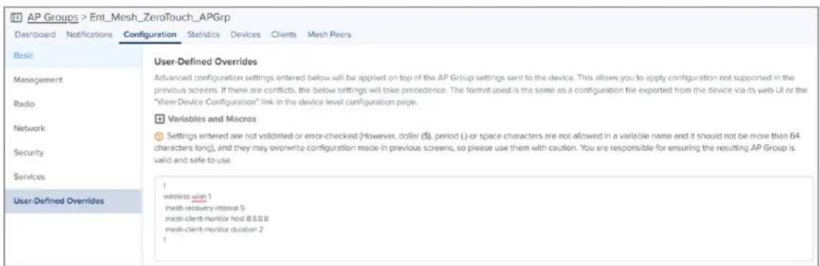
CLI configuration:
ap(config)# wireless wlan 1
ap(config-wlan-1)# mesh client
ap(config-wlan-1)# ssid CAMBIUM_MESH_BASE
ap(config-wlan-1)# vlan 1
ap(config-wlan-1)# security wpa2-psk
ap(config-wlan-1)# passphrase 12345678
ap(config-wlan-1)# band 5GHz
ap(config-wlan-1)# mesh-recovery-interval 30
ap(config-wlan-1)# mesh-client-monitor duration 5
ap(config-wlan-1)# mesh-client-monitor host 8.8.8.8
Mesh Recovery (MR)
To support plug and play Mesh deployment model, suggest configuring the MR profile on the MB result, factory reset APs/New APs can establish a mesh connection to the MB right away (out of
A recovery profile is also useful when an MC loses connectivity to a base due to misconfiguration connection that causes frequent drops.
To configure the MR:
cnMaestro configuration:

CLI configuration:
ap(config-wlan-1)# mesh recovery
ap(config-wlan-1)# vlan 1
ap(config-wlan-1)# band 5GHz
Please refer to the Cambium Zero touch White paper on mesh for more information on Zero touch Mesh.
Mesh SNR-threshold
SNR-threshold configuration parameter is supported via CLI and can also be provisioned via cnMaestr the MB WLAN profile. This parameter helps in maintaining the quality of the mesh link by denying has a low SNR value than the configured threshold.
cnMaestro configuration:

CLI configuration:
ap(config-wlan-1)# mesh snr-threshold 60
Mesh Mode
Enterprise Wi-Fi APs support multi-radio, and by default channel distribution, is enabled. When channel distribution is enabled, each radio is mapped with a group of channels that it can operate.
When a device operates in MC, it will scan channels that are supported by the radio. Hence, the possibility that MC will never connect to MB. Mesh mode configuration is supported at the RADIO maintain the consistent link, the user has provision exclusively to configure mode on the radio to Mesh Clients are always connected to the network. To configure the Mesh mode:
cnMaestro configuration:

CLI configuration:
ap(config-radio-1)# allowed-wlan-modes mesh
Mesh ACL
ACL can be used to make sure that the Mesh Client connecting to the base AP is a known A Client radio MAC address can be added to the Mesh Base AP to achieve this.
Following are the various modes of MAC authentication supported by Enterprise Wi-Fi APs:
- Allow
To enable this mode, add the list of MAC addresses either to be allowed or denied under "mac authentication list
cnMaestro configuration:

CLI configuration:
ap(config-wlan-1)# mac-authentication policy allow
- Deny
To enable this mode, add the list of MAC addresses either to be allowed or denied under "mac authentication list
cnMaestro configuration:

CLI configuration:
ap(config-wlan-1)# mac-authentication policy deny
- RADIUS
To enable this mode, configure the device (described in Chapter 7: Radius server section) on the MB WLAN profile as below:
cnMaestro configuration:

CLI configuration:
ap(config-wlan-1)# mac-authentication policy radius
- cnMaestro
To enable this mode, define the MAC addresses allowed or denied as described in the cnMaestro Premises User Guide Association ACL section and configure the device on the MB WLAN profile as
cnMaestro configuration:
MAC Authentication
Policy

CLI configuration:
ap(config-wlan-1)# mac-authentication policy cnMaestro
Mesh Auto Detect Backhaul
Mesh Auto Detect backhaul is a mechanism to enable MB or MC WLAN profile based on the state ethernet of a device that is operating in mesh mode. Enterprise Wi-Fi APs are multi-radio and multi-supported, hence there are multiple ways of configuring this feature based on the number of ether of a device.
In general, customers use a single AP group to configure any mesh devices in a network. When is enabled, the device is intelligent enough to decide whether it has to operate in MB or MC n are different scenarios (AP2), where this feature can trigger a change in the mesh mode of the
Scenario 1
When a single AP Group is used for both MB and MC, AP2 can decide its mesh mode based eth2 connections. To auto-trigger, the type of mesh mode below configuration needs to be pushed APs in the mesh link.
Based on eth1 and eth2 physical link and reachability to 8.8.8.8 determines the state of mesh mo Below is a matrix that explains AP2 behavior:
| Eth 1 Eth 2 | 8.8.8.8 | Reachability | MB MC | |
| ConnectedNo data enabled | Connected with no network reachability | No Disabled Enabled | ||
| ConnectedNo data enabled | Connected with network reachability | Yes Enabled Disabled | ||
| ConnectedData-enabled | Connected with no network reachability | No Disabled Enabled | ||
| ConnectedData-enabled | Connected with no network reachability | Yes Enabled Disabled | ||
| ConnectedData-enabled | Connected with network reachability | Yes Enabled Disabled |
Figure 95 Deployment Scenario 1
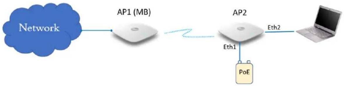
flowchart
graph LR
    A["Network"] --> B["AP1 (MB)"]
    B --> C["AP2"]
    C --> D["Laptop"]
    C -->|Eth1| E["PoE"]
    C -->|Eth2| D
Scenario 2
When a single AP Group is used for both MB and MC, AP2 can decide its mesh mode based connections. To auto-trigger, the type of mesh mode below configuration needs to be pushed on at the mesh link.
| Eth 1 8.8.8.8 Reachability MB MC | ||
| • ConnectedNo data enabled | No Disabled Enabled | |
| • ConnectedData-enabled | No Disabled Enabled | |
| • ConnectedData-enabled | Yes Enabled Disabled |
Figure 96 Deployment Scenario 2

flowchart
graph LR
    A["Network"] --> B["AP1 (MB)"]
    B --> C["AP2"]
    C --> D["Laptop"]
    C --> E["PoE"]
    style A fill:#blue,stroke:#333
    style B fill:#white,stroke:#333
    style C fill:#white,stroke:#333
    style D fill:#gray,stroke:#333
    style E fill:#yellow,stroke:#333
Scenario 3
When a single AP Group is used for both MB and MC, AP2 can decide its mesh mode based connections. To auto-trigger, the type of mesh mode below configuration needs to be pushed on a
the mesh link.
| Eth 1 8.8.8.8 Reachability MB MC | ||
| Connected No Disabled Enabled |
Figure 97 Deployment Scenario 3

flowchart
graph LR
    A["Network"] --> B["AP1 (MB)"]
    B --> C["AP2"]
    C --> D["PoE"]
    style A fill:#bluebubble
    style B fill:#white bubble
    style C fill:#white bubble
    style D fill:#yellow bubble
    note right of B: "AP1 (MB)"
    note right of C: "Eth1"
To enable this configuration either from cnMaestro or CLI, follow the below guidelines:
cnMaestro configuration:
Mesh Client

Mesh Base


CLI configuration:
Mesh Client
ap(config-wlan-1)# mesh client
ap(config-wlan-1)# ssid CAMBIUM_MESH_BASE
ap(config-wlan-1)# vlan 1
ap(config-wlan-1)# security wpa2-psk
ap(config-wlan-1)# passphrase 12345678
ap(config-wlan-1)# band 5GHz
ap(config-wlan-1)# mesh-client-monitor duration 5
ap(config-wlan-1)# mesh-client-monitor host 8.8.8.8
Mesh Base
ap(config-wlan-7)# mesh base
ap(config-wlan-7)# ssid CAMBIUM_MESH_BASE
ap(config-wlan-7)# vlan 1
ap(config-wlan-7)# security wpa2-psk
ap(config-wlan-7)# passphrase 12345678
ap(config-wlan-7)# band 5GHz
ap(config-wlan-7)# mesh-auto-detect-backhaul
ap(config-wlan-7)# mesh-auto-detect-backhaul monitor-host
Mesh Muti-Hop
This topology is not a recommended solution but can be deployed in foreseen situations. In this 1 deployment, intermediate devices (AP2) in mesh links require both MB and MC to be enabled.
Figure 98 Multi-Hop deployment Scenario
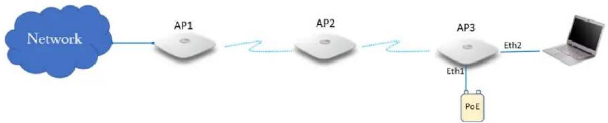
flowchart
graph LR
    A["Network"] --> B["AP1"]
    B --> C["AP2"]
    C --> D["AP3"]
    D --> E["Laptop"]
    D -->|Eth1| F["PoE"]
    D -->|Eth2| G["Computer"]
cnMaestro configuration:

CLI configuration:
ap(config-wlan-7)# mesh base
ap(config-wlan-7)# ssid CAMBIUM_MESH_BASE
ap(config-wlan-7)# vlan 1
ap(config-wlan-7)# security wpa2-psk
ap(config-wlan-7)# passphrase 12345678
ap(config-wlan-7)# band 5GHz
ap(config-wlan-7)# mesh-auto-detect-backhaul
ap(config-wlan-7)# mesh-auto-detect-backhaul monitor-host
ap(config-wlan-7)# mesh-auto-detect-backhaul multi-hop
Mesh Roaming
From Release 6.4 onwards Enterprise Wi-Fi APs support mesh roaming. For this functionality to be enable the below parameters (MB and MC) on mesh devices.
Mesh Base configuration
Enable 802.11r on the MB WLAN profile to support MC roaming.
cnMaestro configuration:

CLI configuration:
ap(config-wlan-1)# fast-roaming 802.11r
Mesh Client configuration
For Mesh Client roaming to be operational, enable or configure the below parameters on the radio the mesh client is enabled.
Table 63 Mesh Client configuration parameter
| Parameters Description | Range Default | ||
| mesh-client-bgscan | Provision to enable the Mesh Client background | scan. - | Disabled |
| mesh-client-bgscan channel-list | The list of channels the Mesh Client needs to look for AP. | to scan to - | |
| mesh-client-bgscan long-interval | Once APs RSSI goes above this value, scan every configured interval. | in 600als and seconds | 300 |
| mesh-client-bgscan roaming-rssi-threshold | APs RSSI threshold to initiate a scan and roam. | -100-0 dBm | -65 |
| mesh-client-bgscan short-interval | Once AP's RSSI drops below this value, the scan will be triggered and follows the scan | in 800diate seconds | 60 |
cnMaestro configuration:
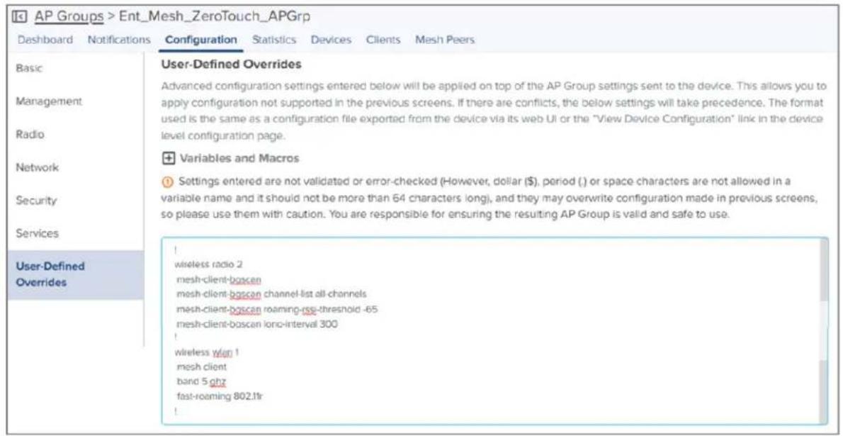
CLI configuration:
ap(config-radio-2)# mesh-client-bgscan
ap(config-radio-2)# mesh-client-bgscan channel-list all-channels
ap(config-radio-2)# mesh-client-bgscan roaming-rssi-threshold -65
ap(config-radio-2)# mesh-client-bgscan long-interval 300
ap(config-radio-2)# mesh-client-bgscan short-interval 60
Mesh link-Sample configuration
This section briefs about the configuration of the device to get a mesh link established with different deployment scenarios.
VLAN 1 as the management interface
Follow the below CLI commands to establish a mesh link with VLAN 1 as the management interfa
- To configure MB and MR, following are the commands:
- WLAN MB profile
cnMaestro configuration:

CLI configuration:
ap(config-wlan-1)# mesh base
ap(config-wlan-1)# ssid CAMBIUM_MESH_BASE
ap(config-wlan-1)# security wpa2-psk
ap(config-wlan-1)# passphrase 12345678
ap(config-wlan-1)# VLAN 1
ap(config-wlan-1)# band 5GHz
- WLAN MR profile
cnMaestro configuration:

CLI configuration:
ap(config-wlan-1)# mesh recovery
ap(config-wlan-1)# vlan 1
ap(config-wlan-1)# band 5GHz
- To configure MC, following are the commands:
cnMaestro configuration:

CLI configuration:
ap(config-wlan-1)# mesh client
ap(config-wlan-1)# ssid CAMBIUM_MESH_BASE
ap(config-wlan-1)# vlan 1
ap(config-wlan-1)# security wpa2-psk
ap(config-wlan-1)# passphrase 12345678
ap(config-wlan-1)# band 5GHz
ap(config-wlan-1)# mesh-recovery-interval
ap(config-wlan-1)# mesh-recovery-interval 30
ap(config-wlan-1)# mesh-client-monitor
ap(config-wlan-1)# mesh-client-monitor duration 5
ap(config-wlan-1)# mesh-client-monitor host 8.8.8.8
- To configure the Management VLAN interface, following are the commands:
cnMaestro configuration:

CLI configuration:
ap(config)# interface vlan 1
ap(config-vlan-1)# ip address dhcp
ap(config-vlan-1)# exit
ap(config)# interface eth 1
ap(config-eth-1)# switchport mode trunk
ap(config-eth-1)# switchport trunk native vlan 1
ap(config-eth-1)# switchport trunk allowed vlan 2-4094
Non-VLAN 1 as the management interface
Follow the below CLI commands to establish a mesh link with non-VLAN 1 as the management in
- To configure MB and MR, following are the commands:
- WLAN MB profile
cnMaestro configuration:
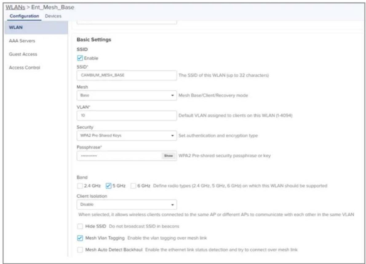
CLI configuration:
ap(config-wlan-1)# mesh base
ap(config-wlan-1)# ssid CAMBIUM_MESH_BASE
ap(config-wlan-1)# security wpa2-psk
ap(config-wlan-1)# passphrase 12345678
ap(config-wlan-1)# VLAN 10
ap(config-wlan-1)# band 5GHz
- WLAN MR profile
cnMaestro configuration:

CLI configuration:
ap(config-wlan-1)# mesh recovery
ap(config-wlan-1)# vlan 10
ap(config-wlan-1)# band 5GHz
- To configure MC, following are the commands:
cnMaestro configuration:

CLI configuration:
ap(config-wlan-1)# mesh client
ap(config-wlan-1)# ssid CAMBIUM_MESH_BASE
ap(config-wlan-1)# vlan 10
ap(config-wlan-1)# security wpa2-psk
ap(config-wlan-1)# passphrase 12345678
ap(config-wlan-1)# band 5GHz
ap(config-wlan-1)# mesh-recovery-interval
ap(config-wlan-1)# mesh-recovery-interval 30
ap(config-wlan-1)# mesh-client-monitor
ap(config-wlan-1)# mesh-client-monitor duration 5
ap(config-wlan-1)# mesh-client-monitor host 8.8.8.8
- To configure the Management non-VLAN interface, the following are the commands: cnMaestro configuration:
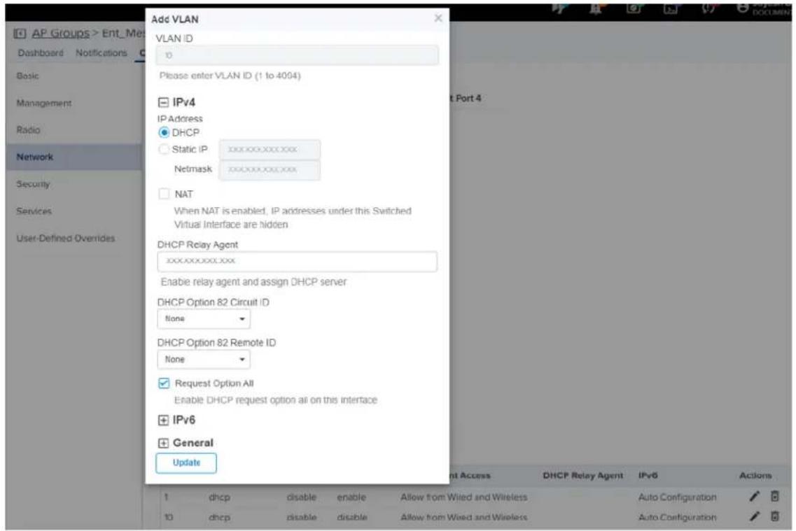
CLI configuration:
ap(config)# interface vlan 10
ap(config-vlan-10)# ip address dhcp
ap(config-vlan-10)# ip dhcp request-option-all
ap(config)# interface eth 1
ap(config-eth-1)# switchport mode trunk
ap(config-eth-1)# switchport trunk native vlan 1
ap(config-eth-1)# switchport trunk allowed vlan 2-4094
Typical use-cases
• Wi-Fi access in areas with no cable run
° Add an AP indoor/outdoor APs for the areas that are difficult to reach
- Small retail location with one AP near an Ethernet outlet, and another in the middle of the I no easy cable run.
- Resolving coverage issues.
- Plug coverage holes
- Extend range outdoors
° An XV2-2T Hotspot in a parking lot outside a building, with XV2-2s providing Wi-Fi within th
Additional mesh topology supported

Note
The following topology supports zero touch provisioning and single AP group configuration.

flowchart
graph LR
    A["Network"] --> B["AP1"]
    B --> C["AP2"]
    C --> D["Printer"]
    D --> E["Computer"]
Wired devices behind mesh client AP
In this scenario, when wired devices are connected to the mesh client AP (AP2), the AP will sup touch provisioning and both base and client APs will have the same configuration (AP group). MesI have the capability to connect a separate LAN segment (containing wired devices) to the WLAN.
When an AP, with factory default configuration, is connected in the above scenario, the device wait seconds to obtain the IP address from the wired side. If the device does not receive any IP ad wired side, then mesh recovery is triggered. If the device restarts, the device waits for 360 second the IP address from the wired side. If the device does not receive any IP address from the wired mesh recovery is triggered.
Guest Access Portal - Internal
Introduction
Guest Access Portal services offer a simple way to provide secure access to the internet for user devices using a standard web browser. Guest access portal allows enterprises to offer authenticated to the network by capturing and re-directing a web browser's session to a captive portal login pa the user must enter valid credentials to be granted access to the network.
Modes of Captive Portal Services supported by Enterprise Wi-Fi AP devices:
- Internal Access: Captive Portal server is hosted on the access point and is local to the AP.
- External Access: Enterprise Wi-Fi AP is integrated with multiple third-party Captive Portal services vendors. Based on the vendor, the device needs to be configured. For more information, see Guest Access Portal - External.
- cnMaestro: Captive Portal services are hosted on cnMaestro where various features like Social login, Voucher login, SMS login, and Paid login are supported. For more information, see Guest Access – cnMaestro.
- EasyPass: EasyPass Access Services enable you to easily provide secure and controlled access to users and visitors on your Wi-Fi network.
This chapter describes about Internal Captive Portal services supported by Enterprise Wi-Fi APs. The following figure displays the basic topology of testing the Internal Captive Portal Service.
Figure 99 Topology
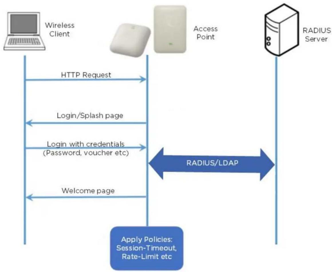
flowchart
graph TD
    A["Wireless Client"] -->|HTTP Request| B["Access Point"]
    B -->|RADIUS/LDAP| C["RADIUS Server"]
    C -->|Login/Splash page| B
    B -->|Login with credentials (Password, voucher etc)| A
    A -->|Welcome page| C
    C -->|Apply Policies: Session-Timeout, Rate-Limit etc| A
Configurable parameters
The below figure displays multiple configurable parameters supported for Internal Guest Access hosted AP. Access Policy – Clickthrough.
Figure 100 Guest Access Internal Access Point parameter

Access policy
Click through
When this policy is selected, the user will get a login page to accept Terms and Conditions to get access to the network. No additional authentication is required.
Splash page
Title
You can configure the contents of the splash page using this field. Contents should not exceed n 255 characters.
Contents
You can configure the contents of the splash page using this field. Contents should not exceed n 255 characters.
Terms and conditions
Terms and conditions to be displayed on the splash page can be configured using this field. Terr conditions should not exceed more than 255 characters.
Logo
Displays the logo image updated in URL http(s):/
Background image
Displays the background image updated in URL http(s):/
Redirect parameters
Redirect hostname
Users can configure a friendly hostname, which is added to the DNS server and is resolvable to Wi-Fi AP IP address. This parameter once configured will be replaced with an IP address in the URL provided to wireless stations.
Success action
Provision to configure redirection URL after successful login to captive portal services. Users can co three modes of redirection URL:
- Internal logout Page
After successful login, the wireless client is redirected to the logout page hosted on AP.
- Redirect users to external URL
Here users will be redirected to the URL which we configured on a device as below:
- Redirect users to the Original URL
Here users will be redirected to a URL that is accessed by the user before successful captive authentication.
Redirect
By default, captive portal redirection is triggered when the user accesses either HTTP or HTTPS W enabled, redirection to Captive Portal Splash Page is triggered when an HTTP WWW is accessed by user.
Redirect Mode
There are two redirect modes available:
- HTTP Mode
When enabled, AP sends an HTTP POSTURL to the client.
- HTTP(s) Mode
When enabled, AP sends HTTPS POST URL to the client
Success message
This we can configure so that we can display success message on the splash page after success authentication
Timeout
Session
This is the duration of time which wireless clients will be allowed internet after guest access auth
Inactivity
This is the duration of time after which wireless clients will be requested for re-login.
Whitelist
Provision to configure either lps or URLs to bypass traffic, therefore users can access those IPs or without Guest Access authentication.
Configuration examples
This section briefs about configuring different methods of Internal Guest Access captive portal service hosted on AP.
Access Policy - Clickthrough
Figure 101 Authentication – redirected splash page
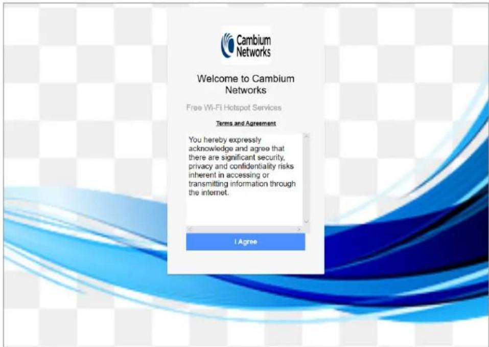
Figure 102 Successful login – redirected splash page
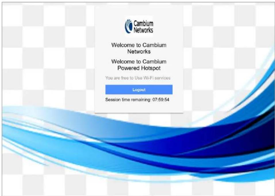
Guest Access Portal - External
Introduction
Guest access WLAN is designed specifically for BYOD (Bring Your Own Device) setup, where large organizations have both staff and guests running on the same WLAN or similar WLANs. Cambium N provides different options to the customers to achieve this based on where the captive portal page and who will be validating and performing the authentication process.
External Hotspot is a smart Guest Access provision supported by Enterprise Wi-Fi AP devices. This of Guest Access provides the flexibility of integrating an external 3rd party Web/Cloud hosted captiv fully customized. More details on third-party vendors who are integrated and certified with Cambium listed in the URL https://www.cambiumnetworks.com/wifi_partners/.
Configurable parameters
Figure 103 displays multiple configurable parameters supported for External Guest Access hosted on AP.
Figure 103 External Hotspot parameter

Access policy
Clickthrough
When this policy is selected, the user will get a login page to accept Terms and Conditions to get access to the network. No additional authentication is required.
WISPr
WISPr clients external server login
Provision to enable re-direction of guest access portal URL obtained through WISPr.
External portal post through cnMaestro
This is required when HTTPS is only supported by an external guest access portal. This option will be enabled minimizes certification. The certificate is required to install only in cnMaestro.
External portal type
Only standard mode configuration is supported by Enterprise Wi-Fi AP products.
Standard
This mode is selected, for all third-party vendors whose Guest Access services is certified and inte with Enterprise Wi-Fi AP products.
Redirect parameters
Success action
Provision to configure redirection URL after successful login to captive portal services. Users can co three modes of redirection URL:
- Internal logout Page
After successful login, the wireless client is redirected to the logout page hosted on AP.
- Redirect users to external URL
Here users will be redirected to the URL which we configured on the device as below:
- Redirect users to the original URL
Here users will be redirected to a URL that is accessed by the user before successful captive authentication.
Redirect
By default, captive portal redirection is triggered when the user accesses either HTTP or HTTPS W enabled, redirection to Captive Portal Splash Page is triggered when an HTTP WWW is accessed t:
user.
Redirect mode
There are two redirect modes available:
- HTTP Mode
When enabled, AP sends an HTTP POSTURL to the client.
- HTTP(s) Mode
When enabled, AP sends HTTPS POST URL to the client
Success message
This we can configure so that we can display success message on the splash page after success authentication
Timeout
Session
This is the duration of time which wireless clients will be allowed internet after guest access auth
Inactivity
This is the duration of time after which wireless clients will be requested for re-login.
Whitelist
Provision to configure either lps or URLs to bypass traffic, therefore users can access those IPs or without Guest Access authentication.
Configuration examples
This section briefs about configuring different methods of External Guest Access captive portal service hosted on AP.
Access Policy - Clickthrough
Figure 104 Authentication – redirected splash page

Figure 105 Successful Login - redirected splash page

Guest Access - cnMaestro
Cambium supports end-to-end Guest Access Portal services with a combination of Enterprise Wi-Fi AF cnMaestro. cnMaestro supports various types of authentication mechanisms for wireless clients to obtain Internet access. For further information about Guest Access Portal:
- For On-Premises, go to https://support.cambiumnetworks.com/files/cnmaestro/ and download the latest cnMaestro On-Premises User Guide.
- For cnMaestro Cloud, refer to the cnMaestro Cloud User Guide.
Auto VLAN
The Auto VLAN is intended to support zero-touch detection and configuration for connected Enterpris Fi APs. New Cambium vendor-specific LLDP TLVs are introduced starting with cnMatrix Release 3.1 t support “pushing” PBA policy data from Enterprise Wi-Fi APs to cnMatrix. The new PBA TLVs are implemented as an extension to the LLDP standard, using its flexible extension mechanism.
From a functional perspective, cnMatrix, acting as the upstream device, includes the PBA authentication in the regularly generated LLDPDUs for a port. The downstream device receives the PBA authentica TLV, and, if policy action data (for example VLANs) is present to be pushed to cnMatrix, a PBA settings TLV is constructed and added to the LLDPDU for the port.
The below table lists the fields that are required for configuring Auto-VLAN:
Table 64 Configuring Auto-VLAN parameters
| Parameters | Description Range Default | ||
| Ildp pba New PBA TLVs is shared with cnMatrix switch. - Enabled | |||
| Ildp pba-auth-key | The shared private key used during PBA TLV authenticbe updated or reset from its default value (by using | cation-enabledthe ‘no’woption).default key | |

Note
lldp pba-auth-key default value cannot be shared due to security concerns.
CLI configuration:
Syntax:
ap(config)# lldp
ap(config)# lldp pba-auth-key
Example:
ap(config)# lldp pba
ap(config)# lldp pba-auth-key 123456789
Device Recovery Methods
Factory reset via 'RESET' button
Table 65 Factory reset via RESET button
| Access Point | Procedure LED Indication | |
| XV3-8 Press | and hold the Reset button for 15 seconds | Both LEDs will be OFF and turned Amber |
| XE5-8 Press | and hold the Reset button for 15 seconds | Both LEDs will be OFF and turned Amber |
| XV2-2 Press | and hold the Reset button for 15 seconds | Both LEDs will be OFF and turned Amber |
| XV2-2T0 Press | and hold the Reset button for 15 seconds | Both LEDs will be OFF and turned Amber |
| XV2-2T1 Press | and hold the Reset button for 15 seconds | Both LEDs will be OFF and turned Amber |
| XE3-4 Press | and hold the Reset button for 15 seconds | Both LEDs will be OFF and turned Amber |
| XE3-4TN Press | and hold the Reset button for 15 seconds | Both LEDs will be OFF and turned Amber |
| XV2-21X Press | and hold the Reset button for 15 seconds | Both LEDs will be OFF and turned Amber |
| XV2-23T Press | and hold the Reset button for 15 seconds | Both LEDs will be OFF and turned Amber |
| XV2-22H Press | and hold the Reset button for 15 seconds | Both LEDs will be OFF and turned Amber |
| X7-35X Press | and hold the Reset button for 15 seconds | Both LEDs will be OFF and turned Amber |
Boot partition change via power cycle
Table 66 Boot partition change via power cycle
| Access Point Procedure | |
| XV3-8 | Follow power ON and off 9 times with an interval of 120 Sec |
(ON) and 5 Sec (O
| Access Point | Procedure |
| XE5-8 Follow | power ON and off 9 times with an interval of 120 Sec (ON) |
| XV2-2 Follow | power ON and off 9 times with an interval of 120 Sec (ON) |
| XV2-2T0 Follow | power ON and off 9 times with an interval of 120 Sec (ON) |
| XV2-2T1 Follow | power ON and off 9 times with an interval of 120 Sec (ON) |
| XE3-4 Follow | power ON and off 9 times with an interval of 120 Sec (ON) |
| XE3-4TN Follow | power ON and off 9 times with an interval of 120 Sec (ON) |
| XV2-21X Follow | power ON and off 9 times with an interval of 120 Sec (ON) |
| XV2-23T Follow | power ON and off 9 times with an interval of 120 Sec (ON) |
| XV2-22H Follow | power ON and off 9 times with an interval of 120 Sec (ON) |
| X7-35X Follow | power ON and off 9 times with an interval of 120 Sec (ON) |
and 5 Sec (OFF)
and 5 Sec (OFF)
I) and 5 Sec (OFF)
) and 5 Sec (OFF)
and 5 Sec (OFF)
) and 5 Sec (OFF)
) and 5 Sec (OFF)
) and 5 Sec (OFF)
J) and 5 Sec (OFF)
and 5 Sec (OFF)
Disable factory Reset Button
User can disable the physical Reset Button on the device by using the below CLI command:
ap(config)# no system hw-reset

Warning
The Reset Button is a key recovery option in situations when an AP gets misconfigured you are unable to connect to the AP.
By disabling the Reset Button, you lose the ability to recover the AP in such scenario:
Command-Line Interface (CLI)
The Enterprise Wi-Fi products support Command-Line Interface (CLI) which helps in configuring as we monitoring the devices.
Show commands
The below table provides Show commands supported in Enterprise Wi-Fi AP:
Table 67 Show commands supported in Enterprise Wi-Fi AP
| SL No | CLI Command Description | |
| Deep Packet Inspection (DPI) | ||
| 1 | show application-statistics by-application | Displays statistics of each application that is accessed by the station connected to the AP. |
| 2 | show application-statistics by-category | Displays statistics of application category that is accessed by the station connected to the AP. |
| Network Information | ||
| 3 | show arp | Displays list of ARP entries learned by AP. |
| 4 | show conntrack | Displays current connection track entries along with application ID Mapping. |
| 5 | show route | Displays IP route information. |
| 6 | show dhcp-pool | Displays the DHCP pool configuration. |
| 7 | show interface brief | Displays interface details such as IP, Netmask, and traffic statistics. |
| 8 | show ip dhcp-client-info | Displays the DHCP options learned by device across all interfaces. |
| 9 | show ip domain-name | Displays learned domain name information. |
| 10 | show ip gw-source-precedence | Displays the Precedence of gateway sources. |
| 11 | show ip interface | Displays IP interface parameters. |
| 12 | show ip name-server | Displays DNS server information. |
| 13 | show ip neighbour | Displays IPv4 neighbour entries. |
| 14 | show ip route | Displays IP route information. |
| 15 | show ipv6 dhcp-client-info | Displays learned DHCPv6 client information. |
| 16 | show ipv6 domain-name | Displays learned domain name information. |
| 17 | show ipv6 gw-source-precedence | Displays the precedence of gateway sources. |
| 18 | show ipv6 interface brief | Displays IPv6 interface parameters. |
| 19 | show ipv6 name-server | Displays DNS server information. |
| 20 | show ipv6 neighbour | Displays neighbour entries. |
| 21 | show ipv6 route | Displays IP route information. |
| Radio Information | ||
| 22 | show auto-rf channel-info | Displays Auto-RF channel information. |
| 23 | show auto-rf history | Displays Auto-RF history. |
| 24 | show wireless band-steer client-cache | Displays band steered client cache. |
| 25 | show wireless mesh ipv6 | Displays IPv6 address of associated mesh clients |
| 26 | show wireless mesh-xtnded-list | Displays mesh extended device list for 2.4 GHz mesh-xtnded-dev-list is enabled. |
| 27 | show wireless neighbors 2.4GHz | Displays 2.4 GHz wireless neighbors. |
| 28 | show wireless neighbors 5GHz | Displays 5G Hz wireless neighbors. |
| 29 | show wireless neighbors 6GHz | Displays 6 GHz wireless neighbors. |
| 30 | show wireless neighbors autocell | Displays Auto-cell neighbors. |
| 31 | show wireless radios channels | Displays supported channels. |
| 32 | show wireless radios mu-mimo-statistics | Displays MU-MIMO statistics of Radios. |
| 33 | show wireless radios multicast-to-unicast | Displays multicast-to-unicast configuration. |
| 34 | show wireless radios ofdma-statistics | Displays OFDMA statistics of Radios. |
| 35 | show wireless radios rf-statistics | Displays statistics of Radios. |
| 36 | show wireless radios statistics | Displays statistics of Radios. |
| 37 | show wireless wlans aggregate-statistics | Displays aggregate statistics of wireless LANs. |
| 38 | show wireless wlans interface | Displays wireless WLAN interface details. |
| 39 | show wireless wlans monitor-host | Displays monitor host information for wireless LAN |
when
| SL No | CLI Command Description | |
| 40 | show wireless wlan statistics | Displays statistics of wireless LANs. |
| Bonjour Information | ||
| 41 | show bonjour-services | Displays Bonjour services available. |
| 42 | show bonjour-statistics | Displays Bonjour rule statistics. |
| System Information | ||
| 43 | show upgrade-status | Displays last upgrade status. |
| 44 | show version | Displays device firmware information. |
| 45 | show timezones | Displays list of timezone locations. |
| 46 | show management details | Displays management status in detail. |
| 47 | show mfgrom | Displays manufacturing ROM details. |
| 48 | show country-codes | Displays a list of supported countries and corresponding country codes. |
| 49 | show boot | Displays device firmware active-backup versions. |
| 50 | show cambium-id | Displays configured Cambium-ID (if any). |
| 51 | show clock | Displays system time. |
| 52 | show config all | Displays current configuration including defaults. |
| 53 | show config dhcp-pools all | Displays DHCP pools configuration including defaults. |
| 54 | show config filter | Displays Filter configuration. |
| 55 | show config wireless all | Displays wireless configuration including defaults. |
| 56 | show config system all | Displays infra configuration including defaults. |
| 57 | show config system interfaces | Displays network interface configuration. |
| 58 | show events | Displays recent event messages. |
| Guest Access | ||
| 59 | show ext-guest clients | Displays information of ext-guest clients. |
| Filters | ||
| 60 | show filter-statistics | Displays filter statistics. |
| LLDP | ||
| 61 | show lldp chassis | Displays local chassis data. |
| 62 | show lldp configuration | Displays configuration. |
| 63 | show lldp interfaces | Displays interfaces data. |
| 64 | show lldp neighbors | Displays neighbors data. |
| 65 | show lldp statistics | Displays statistics. |
| 66 | show power | Displays power conditions. |
| 67 | show packet-capture status | Displays status of packet capture. |
| Real-Time Location System | ||
| 68 | show rtls aeroscout ble-tag-summary | Displays AeroScout BLE-tag summary. |
| 69 | show rtls aeroscout configuration | Displays AeroScout Wi-Fi-tag configuration. |
| 70 | show rtls aeroscout wifi-tag-summary | Displays AeroScout Wi-Fi-tag summary. |
| Tunnel | ||
| 71 | show tunnel-statistics | Displays tunnel statistics. |
| 72 | show tunnel-status details | Displays tunnel parameters. |
| 73 | show ip pppoe-client-info | Displays learned PPPoE client information. |
| 74 | show pppoe-status | Displays PPPoE status. |
Service commands
Service show
The below table provides Service show commands supported in Enterprise Wi-Fi AP:
Table 68 Service show commands supported in Enterprise Wi-Fi AP
| SL No | CLI Command Description | |
| 1 | service show bridge | Displays AP bridge table entries. |
| 2 | service show client-cache | Displays current client status and history of clients and respective parameters. |
| 3 | service show config | Displays configuration from data base. |
| SL No | CLI Command Description | |
| 4 | service show cores | Displays process cores (if any). |
| 5 | service show debug-logs | Displays debug logs of various processes. |
| 6 | service show df | Displays flash status. |
| 7 | service show dmesg | Displays system kernel logs. |
| 8 | service show epsk | Displays ePSK information. |
| 9 | service show ethtool | Displays information and statistics w.r.t Ethernet interfaces. |
| 10 | service show guest-portal whitelist wlan | Displays whitelist entries either configured or auto-selected by a device in a guest portal WLAN profile. |
| 11 | service show ifconfig | Displays status and statistics of all interfaces configured and supported on the device. |
| 12 | service show iperfd-logs | Display IPERF logs when iperfd daemon is enabled on device. |
| 13 | service show iwconfig | Displays status and statistics of all Wireless interfaces configured on the device. |
| 14 | service show last-reboot-reason | Displays the reason for the last reboot of the AP. |
| 15 | service show last-reboot-state watchdog | Displays if the last reboot reason is due to watchdog. |
| 16 | service show mcastsnoop | Displays multicast-snoop tables. |
| 17 | service show mdnsd-statistics | Displays mDNS packet stats on mdnsd. |
| 18 | service show memory | Displays memory information. |
| 19 | service show netstat | Displays network socket connections. |
| 20 | service show ps | Displays a list of processes. |
| 21 | service show ps-restart-history | Displays history of process restart on the AP. |
| 22 | service show route | Displays routing table. |
| 23 | service show top | Displays process activity status. |
Service system
The below table provides Service system commands supported in Enterprise Wi-Fi AP:
Table 69 Service system commands supported in Enterprise Wi-Fi AP
| SL No | CLI Command Description | |
| 1 | service boot backup-firmware | Helps to boot to other partition. |
| 2 | service clear-cores | Clear system core files (if any). |
| 3 | service clear-dhcp-pool | Clear DHCP pool allocated addresses. |
| 4 | service debuglogging-level> | Commands to enable debugging of processes at various logging levels. |
| 5 | service flash-leds | Flash system LEDs help identify this device visually. |
| 6 | service radio apstats | Displays aggregate statistics of all wireless interfaces. |
| 7 | service radio athstats | Displays aggregate Radio traffic statistics. |
| 8 | service radio iwpriv | Displays supported iwpriv commands. |
| 9 | service radio thermaltool | Displays radio current operating temperature. |
| 10 | service schedule reload | Reboot AP at the specified time. |
| 11 | service ssh host add | Add a host and key to the known hosts list. |
| 12 | service ssh host del | Delete a host and key from the known hosts list. |
| 13 | service system-trace | Start a trace session for troubleshooting. |
| 14 | service test leds | Displays test LEDs. |
| 15 | service test radio | Displays status and configured Radio. |

Note
This feature is available from cnMaestro 4.1.0 and later versions only.
The cnMaestro X Assurance feature provides enhanced visibility into the health of Wi-Fi client connec including root cause analysis of failures with possible recommended actions. It also provides analytics aggregated data that can help to improve clients connectivity in the Wi-Fi network.
The cnMaestro X Assurance feature analyzes the Wi-Fi client connection events and helps to troubles common network connectivity and performance issues such as the following:
- Connectivity—Association, authentication, and network connectivity services, such as DHCP and DNS transaction failures.
- Poor Performance—Low RSSI, low data rate, AAA, DHCP, DNS transaction latency.
For more information, refer to the cnMaestro User Guide.
MarketApps
The MarketApps feature in cnMaestro offers customized solutions for efficiently managing Wi-Fi service residential settings, such as multi-dwelling units (MDUs) and apartment complexes. It provides specialized tools (applications or Apps) that enhance operational efficiency and cater to the distinct requirements both property managers and residents.
Target audience
- Property managers—The MarketApps feature empowers property managers to centrally administer Wi-Fi access across their properties. They can set up community-wide Wi-Fi networks and manage personal Wi-Fi networks for local residents.
- Residents—Residents can set up and manage their own Wi-Fi networks within the community, ensuring personalized and secure Internet access.
- Solution providers—Solution providers can utilize MarketApps to offer tailored Wi-Fi solutions, enhancing network performance and user satisfaction in multi-dwelling units and apartment complex
Benefits
- Centralized management—Property managers can oversee and control Wi-Fi access across multiple units or buildings from cnMaestro.
- Customization—Residents can set up personal Wi-Fi networks with customized SSIDs and password enhancing their user experience.
To access MarketApps, navigate to Network Services > MarketApps in cnMaestro.
For more information on configuring and viewing MarketApps, refer to the cnMaestro User Guide.
CLI configuration
To enable MarketApps using AP CLI, execute the following command:
ap(config)# wireless wlan 2
ap(config)# epsk cnMaestro
AFC
The XE3-4TN Enterprise Wi-Fi 6E Access Point (AP) is designed to support Standard Power operation 6 GHz band for the outdoor deployments. Standard Power operation enables extended coverage and higher transmit power up to 36 dBm EIRP making it suitable for enterprise-grade and outdoor wire networks.
However, Standard Power operation in the 6 GHz band introduces regulatory requirements to prevent interference with incumbent licensed services such as fixed microwave links and public safety communications. To address this, the Federal Communications Commission (FCC) in the United States Innovation, Science and Economic Development (ISED) in Canada mandate the use of Automated Frequency Coordination (AFC) for all Standard Power Access Points.
The XE3-4TN AP has a built-in GPS receiver with the external antenna connector to automatically co-geographical co-ordinates (latitude, longitude, and height).
This chapter describes the following topics:
• Supported AP firmware version
• Supported cnMaestro version
• Supported countries
- AFC
Supported AP firmware version
AFC is supported in APs running Enterprise Wi-FI AP firmware version 7.1.1 and later.
Supported cnMaestro version
AFC is supported on cnMaestro Cloud.
Supported countries
AFC is supported only in the United States of America (USA) and Canada countries.
AFC 6 GHz frequency range support
| Sl. No | Country 6 GHz frequency range |
| 1 United States of America (USA) U-NII-5: 5925 - 6425 MHzU-NII-7: 6525 - 6865 MHz | |
| 2 Canada U-NII-5: 5925 - 6425 MHzU-NII-6: 6425 - 6525 MHz | |

Note
* U-NII 6 will be supported for Canada in a future release.
Prerequisites for AFC Operation
The following prerequisites are required for AFC to operate feasibly.
• cnMaestro Cloud management
AP must be managed from cnMaestro Cloud
• IP network connection to the AFC server
- Establish connectivity between the AP and the AFC server.
- Whitelist the following URLs in the firewall:
■ https://api.qcs.qualcomm.com
■ https://afcapi.qcs.qualcomm.com
■ https://afcapi.canada.qcs.qualcomm.com
- GPS antenna
The AP must be connected with the Cambium supplied GPS antenna. (Part number: ANT-GPS-C) Ensure that the GPS antenna is clearly exposed to the sky.
- AP placement
AP placement must be configured as outdoor in the cnMaestro AP Group configuration.
AFC Operation

flowchart
graph TD
    A["CNMaestro Cloud"] -->|AP Registration| B["AFC"]
    B --> C["FCC Database"]
    A --> D["AFC Data Fetch"]
    D --> B
    E["XE3-4TN"] --> A
    F["Qualcomm AFC"] --> B
Steps 1 to 6 are part of a one-time procedure for APs that are onboarded to cnMaestro for the for APs that are running factory default configuration.
1. AP onboarding and registration
a. When an AP (in US or Canada, and with 6 GHz capability) is powered on and onboarded to cnMaestro.
b. The AP sends a registration message with an AFC flag to indicate it needs AFC.
2. cnMaestro contacts AFC server
a. cnMaestro communicates with the AFC server and retrieves the following:
- Shared secret (authentication key)
- Registration URL
• Spectrum Inquiry URL
b. cnMaestro shares the above information with the AP.
3. AP sends request to obtain AFC token
a. AP sends a request using the shared secret and registration URL to obtain the AFC token.
4. AP waits for the GPS lock
a. AP obtains information from the GPS receiver on the location (latitude, longitude, altitude).
5. AP sends Spectrum Availability Request to AFC server
a. AP sends a Spectrum Inquiry Request to the AFC system using the following parameters:
- The AFC token
• The GPS location (latitude, longitude, altitude)
b. AFC server responds with the following:
- Permitted frequency channels
- Allowed power levels (EIRP)
• Spectrum grant validity period
6. AP activates 6 GHz radio based on AFC response
a. The AP configures its 6 GHz radio using the AFC response and starts operation.
b. Once AFC operation has started AP does not allow any static channels or static power setting
7. Periodic Spectrum Validity Check
a. The AFC server provides an expiry time (usually 22–24 hours).
b. AP monitors expiry and renews the spectrum grant before it expires.
c. If the spectrum grant changes, AP reconfigures channels/power; if unchanged, operation continu
8. Reboot or Failure Scenarios
a. On reboot, AP uses the existing shared secret and token if still valid.
b. If not valid, the AP repeats the registration and inquiry process.
c. Any intermediate failures use cached valid data until expiry.

Note
The AP must be operating with IPv4 address. The Qualcomm AFC server currently does fully support IPv6 addresses.
AFC information in dashboard
Below is the AFC information shown in the XE3-4TN AP device dashboard from cnMaestro Cloud.

Note
Altitude is in meters.
AFC Information
| Status | Success |
| Token | Obtained |
| Last Updated | 25 Aug 2025, 02:51 PM |
| Location | Long: , Lat: |
| Expiry | 26 Aug 2025, 02:19 AM |
| Version | 1.4 |
| Description | Success |
| Allowed Channels (EIRP) | 1 (36), 5 (36), 9 (36), 13 (36), 17 (36), 21 (36), 25 (36), 29 (36), 33 (36), 37 (36), 41 (36), 45 (36), 49 (36), 53 (36), 57 (36), 61 (36), 65 (36), 69 (36), 73 (36), 77 (36), 81 (36), 85 (36), 89 (36), 93 (36), 117 (36), 121 (36), 125 (36), 129 (36), 133 (36), 137 (36), 141 (36), 145 (36), 149 (36), 153 (36), 157 (36), 161 (36), 165 (36), 169 (36), 173 (36), 177 (36), 181 (36) Allowed in AP group |
| Possible Channels | 1, 5, 9, 13, 17, 21, 25, 29, 33, 37, 41, 45, 49, 53, 57, 61, 65, 69, 73, 77, 81, 85, 89, 93, 117, 121, 125, 129, 133, 137, 141, 145, 149, 153, 157, 161, 165, 169, 173, 177, 181 |
| GPS Information | |
| Fix Type | 3D |
| GNSS | GPS (United States) |
| Satellites (Used/Discovered) | 10 / 19 |
| Location | |
| Axis (Major/Minor) | 9 / 9 |
| Altitude | 260 |
| Altitude Type | AMSL |
| Vertical Uncertainty | 23 |
| Timestamp | 25 Aug 2025, 02:34 PM |
GPS configuration CLIs
The APs must be configured with placement as outdoor. By default, GPS is enabled on the APs additional GPS-specific configuration is required. Cambium recommends configuring GPS parameters to t default values. Following is the list of CLI commands for configuring GPS on APs:
<XE3-4TN-AP>(config)#gps
<XE3-4TN-AP>(config-gps)#shutdown
<XE3-4TN-AP>(config-gps)#success-interval <interval in seconds>
<XE3-4TN-AP>(config-gps)#failure-interval <interval in seconds>
<XE3-4TN-AP>(config-gps)#max-accuracy <in meters>
Following are the default values of the above parameters:
• GPS is enabled by default
• Success interval—300 seconds
- Failure interval—30 seconds
• Max accuracy—100 meters

Note
If the AP reads the location information successfully then we will read the GPS data in success interval and default value is 600 seconds.
However, if location is not read successfully, then the AP will read the GPS data in n seconds.
AFC Troubleshooting
Verify GPS information received by the AP
From cnMaestro device dashboard verify that GPS information is populated. If it is not populated, v using the remote CLI option.
If GPS information is not displayed, verify that the AP's GPS antenna is securely connected and h unobstructed view of the sky.

Verify AFC server connection status and information
From cnMaestro device dashboard verify that AFC server information is populated. If it is not popular to verify using the remote CLI option.
If the AP is not receiving any information from the AFC server, ensure AP has internet connectivit
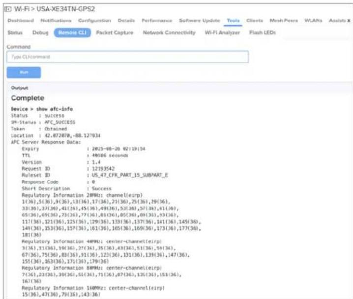
AFC events
AP contacts the AFC server and turns on the radio within five to six minutes.
AFC events shown in the cnMaestro device events window.

Glossary
| Term Definition | |
| AP Access | Point Module. One module that distributes network or Internet services to modules. |
| API Application | Application Program Interface |
| ARP Address | Resolution Protocol. A protocol defined in RFC 826 to allow a network correlate a host IP address to the Ethernet address of the host. |
| BT Bluetooth | |
| DFS See | Dynamic Frequency Selection |
| DHCP Dynamic Host Configuration Protocol defined in RFC 2131. The protocol that enables a device to be assigned a new IP address and TCP/IP parameters, including a default gateway, whenever the device reboots. Thus, DHCP reduces configuration time, conserves IP addresses, and allows modules to be moved to a different network within the system. | |
| Ethernet Protocol | Any of several IEEE standards that define the contents of frames that are transferred from network element to another through Ethernet connections. |
| FCC Federal Communications Commission of the U.S.A. | |
| GPS Global Positioning System. A network of satellites that provides absolute time to earth, which use the time signal to synchronize transmission and reception interference) and to provide reference for troubleshooting activities. | |
| UI User | interface. |
| HTTP Hypertext Transfer Protocol, used to make the Internet resources available on the World Wide Web. | |
| HTTPS Hypertext Transfer Protocol Secure | |
| HT High | Throughput |
| IP Address | The 32-bit binary number identifies a network element by both network and Subnet Mask. |
| IPv4 The | traditional version of Internet Protocol, defines 32-bit fields for data transmission. |
| LLDP Link | Layer Discovery Protocol |
| MAC Address | Media Access Control address. The hardware address that the factory assigns to the mode for identification in the Data Link layer interface of the Open Systems Interconnection system. This address serves as an electronic serial number. |
| MIB Management Information Base. Space that allows a program (agent) in the network to relay information to a network monitor about the status of defined variables (objects). | |
| MIR See | Maximum Information Rate. |
| PPPoE Point to Point Protocol over Ethernet. Supported on SMs for operators who use PPPoE in other parts of their network operators who want to deploy PPPoE to realize per-subscribe authentication, metrics, and usage control. | |
| Proxy Server | Network computer that isolates another from the Internet. The proxy server communicates the other computer, and sends replies to only the appropriate computer which has an II address that is not unique or not registered. |
| PoE Power over Ethernet. | |
| SLA Service Level Agreement | |
| VLAN Virtual local area network. An association of devices through software that contains broadcast traffic, as routers would, but in the switch-level protocol. | |
| VPN A virtual private network for communication over a public network. One typical use is to connect remote employees, who are at home or in a different city, to their corporate r over the Internet. Any of several VPN implementation schemes are possible. SMs support L2TP over IPSec (Level 2 Tunneling Protocol over IP Security) VPNs and PPTP (Point to Tunneling Protocol) VPNs, regardless of whether the Network Address Translation (NAT) feature enabled. | |
Appendix
This appendix contains the following topics:
• Supported RADIUS Attributes
• Supported DFS channels
• Supported 6 GHz countries
• Priority order for parameters
• Best practices for wireless clients seamless roaming across APs
Supported RADIUS Attributes
This topic lists the following RADIUS override attributes that are supported on Enterprise Wi-Fi APs:
• WISPr VSAs (Vendor ID: 14122)
• Cambium VSAs (Vendor ID: 17713)
• Standard RADIUS attributes
• RADIUS attributes in authentication and accounting packets with WPA2-Enterprise security
• Supported CoA messages
WISPr VSAs (Vendor ID: 14122)
Table 70 lists the WISPr vendor-specific attributes (VSAs) supported on Enterprise Wi-Fi APs.
Table 70 WISPr VSAs
| Attribute Value | Attribute Description Attribute Type | RADIUS Message Types Accounting Messages WPA2 / | WPA3 - Enterprise Authentication Support | Guest Access Support | |||||
| Request | Response / Challenge | Accept | Start | Interim Stop | |||||
| 2 | WISPr-Location-Name | string Yes | -NA- No | Yes Yes Yes | Yes | Yes | |||
| 7 | WISPr-Bandwidth-Max-Up | integer | No | No | Yes | No | No | No | Yes |
| 8 | WISPr-Bandwidth-Max-Down | integer | No | No | Yes | No | No | No | Yes |
| 9 | WISPr-Session-Terminate-Time | string | No | No | Yes | No | No | No | Yes |
Table 71 lists the WISPr VSAs supported on Enterprise Wi-Fi APs with CoA support.
Table 71 WISPr VSAs with CoA
| Attribute Value | Attribute Description | Attribute Type | RADIUS Message Types Accounting Messages CoA Support with Guest Access | CoA Support with WPA2 / - Enterprise Authentication | |||||
| Request | Response / Challenge | Accept | Start | Interim Stop | |||||
| 2 | WISPr-Location-Name | string Yes | -NA- No | Yes Yes Yes | -NA- | -NA- | |||
| 7 | WISPr-Bandwidth-Max-Up | integer | No | No | Yes | No | No | No | Yes |
| 8 | WISPr-Bandwidth-Max-Down | integer | No | No | Yes | No | No | No | Yes |
| 9 | WISPr-Session-Terminate-Time | string | No | No | Yes | No | No | No | Yes |
Cambium VSAs (Vendor ID: 17713)
Table 72 lists the Cambium Networks VSAs supported on Enterprise Wi-Fi APs.
Table 72 Cambium VSAs
| Attribute Value | Attribute Description | Attribute Type | RADIUS Message Types | Accounting Messages | WPA2 / WPA3 - Enterp | Guest Access Support | ||||
| Request | Response / Challenge | Accept | Start | Interim Stop | ||||||
| 151 | Cambium-Wi-Fi-Quota-Up | integer | No | No | Yes | No | No | No | -NA- | Yes |
| 152 | Cambium-Wi-Fi-Quota-Down | integer | No | No | Yes | No | No | No | -NA- | Yes |
| 155 | Cambium-Wi-Fi-Quota-Total | integer | No | No | Yes | No | No | No | -NA- | Yes |
| Attribute Value | Attribute Description Attribute Type | RADIUS Message Types Accounting Messages WPA2 / Authentication Support | Guest Access Support | |||||
| Request | Response / Challenge | Accept | Start | Interim Stop | ||||
| 153 | Cambium-Wi-Fi-Quota-Up-Gigaword | integer64 | No No Yes No No No | -NA- | Yes | |||
| 154 | Cambium-Wi-Fi-Quota-Down-Gigaword | integer64 | No No Yes No No No | -NA- | Yes | |||
| 156 | Cambium-Wi-Fi-Quota-Total-Gigaword | integer64 | No No Yes No No No | -NA- | Yes | |||
| 157 | Cambium-VLAN-Pool-ID | string No | No Yes No No No Yes No | |||||
| 159 | Cambium-Traffic-Classes-Acct | TLV | ||||||
| 159.2 | Cambium-Acct-Input-Octets | integer No | No No No Yes | Yes | ||||
| 159.3 | Cambium-Acct-Output-Octets | integer No | No No No Yes | Yes | ||||
| 159.4 | Cambium-Acct-Input-Packets | integer No | No No No Yes | Yes | ||||
| 159.5 | Cambium-Acct-Output-Packets | integer No | No No No Yes | Yes | ||||
Table 73 lists the Cambium Networks VSAs supported on Enterprise Wi-Fi APs with CoA.
Table 73 Cambium VSAs with CoA
| Attribute Value | Attribute Description | Attribute Type | RADIUS | Message Types | Accounting | Messages CoA | Support with Guest Access | CoA Support with WPA2 / WPA3 - Enterprise Authentication | ||
| Request | Response / Challenge | Accept | Start | Interim Stop | ||||||
| 151 | Cambium-Wi-Fi-Quota-Up | integer No | No Yes | No No No | Yes | |||||
| 152 | Cambium-Wi-Fi-Quota-Down | integer No | No Yes | No No No | Yes | |||||
| 155 | Cambium-Wi-Fi-Quota-Total | integer No | No Yes | No No No | Yes | |||||
| 153 | Cambium-Wi-Fi-Quota-Up-Gigaword | integer64 | No No Yes | No No No | Yes | |||||
| 154 | Cambium-Wi-Fi-Quota-Down-Gigaword | integer64 | No No Yes | No No No | Yes | |||||
| 156 | Cambium-Wi-Fi-Quota-Total-Gigaword | integer64 | No No Yes | No No No | Yes | |||||
| 157 | Cambium-VLAN-Pool-ID | string No | No Yes | No No No | ||||||
| 159 | Cambium-Traffic-Classes-Acct | TLV | ||||||||
| 159.2 | Cambium-Acct-Input-Octets | integer No | No No | No Yes Yes | ||||||
| 159.3 | Cambium-Acct-Output-Octets | integer No | No No | No Yes Yes | ||||||
| 159.4 | Cambium-Acct-Input-Packets | integer No | No No | No Yes Yes | ||||||
| 159.5 | Cambium-Acct-Output-Packets | integer No | No No | No Yes Yes | ||||||
Standard RADIUS attributes
Table 74 lists the standard RADIUS attributes supported on Enterprise Wi-Fi APs.
Table 74 Standard RADIUS attributes
| Attribute Value | Attribute Description | Attribute Type | RADIUS Message Types Accounting | ng Messages WPA2 / | WPA3 - Enterprise Authentication Support | Guest Access Support | ||||
| Request | Response / Challenge | Accept | Start | Interim Stop | ||||||
| 11 | Filter-Id (text) - Group-ID | text No | -NA- Yes | No No No Yes | ||||||
| 24 | State | string | Yes | Yes | No | Yes | -NA- | |||
| 25 | Class | string No | -NA- Yes | Yes No No Yes | Yes | |||||
| 27 | Session-Timeout | integer | No -NA- | Yes No No No Yes | Yes | |||||
| 28 | Idle-Timcout | integer | No -NA- | Yes No No No | Yes | |||||
| 64 | Tunnel-Type | enum | No -NA- | Yes No No No Yes | Yes | |||||
| 65 | Tunnel-Medium-Type | enum | No -NA- | Yes No No No Yes | Yes | |||||
| 81 | Tunnel-Private-Group-Id | text No | -NA- Yes | No No No Yes | Yes | |||||
| 85 | Acct-Interim-Interval | integer | No -NA- | Yes No No No Yes | Yes | |||||
| Disconnect | RADIUS packet | |||||||||
| 40 | Disconnect-Request | - | RADIUS packet | -NA- | -NA- | -NA- | -NA- | -NA- | -NA- | -NA- |
| 41 | Disconnect-ACK | - | RADIUS packet | -NA- -NA- | -NA- | -NA- | -NA- | |||
| 42 | Disconnect-NAK | - RADIUS | packet | -NA- -NA- -NA- | -NA- | -NA- | ||||
| 43 | CoA-Request | - RADIUS | packet | -NA- -NA- -NA- | -NA- | -NA- | ||||
| 44 | CoA-ACK | - RADIUS | packet | -NA- -NA- -NA- | -NA- | -NA- | ||||
| 45 | CoA-NAK | - RADIUS | packet | -NA- -NA- -NA- | -NA- | -NA- | ||||
Table 75 lists the standard RADIUS attributes supported on Enterprise Wi-Fi APs with CoA support.
Table 75 Standard RADIUS attributes with CoA
| Attribute Value | Attribute Description | Attribute Type | RADIUS Message Types Accounting Messages CoA Support | Support with Guest Access | CoA Support with WPA2 / - Enterprise Authentication | |||||
| Request | Response / Challenge | Accept | Start | Interim Stop | ||||||
| 11 | Filter-Id (text) - Group-ID | text | No | -NA- | Yes | No | No | No | Yes | Yes |
| 24 | State | string | Yes | Yes | No | Yes | ||||
| 25 | Class | string | No | -NA- | Yes | Yes | No | No | -NA- | -NA- |
| 27 | Session-Timeout | integer | No | -NA- | Yes | No | No | No | -NA- | -NA- |
| 28 | Idle-Timeout | integer | No | -NA- | Yes | No | No | No | -NA- | -NA- |
| 64 | Tunnel-Type | enum | No | -NA- | Yes | No | No | No | -NA- | -NA- |
| Attribute Value | Attribute Description | Attribute Type | RADIUS Message Types Accounting Messages CoA Support with Guest Access | CoA Support with WPA2 / - Enterprise Authentication | |||||
| Request | Response / Challenge | Accept | Start | Interim Stop | |||||
| 65 | Tunnel-Medium-Type | enum No | -NA- Yes | No No No | -NA- -NA- | ||||
| 81 | Tunnel-Private-Group-Id | text No | -NA- Yes | No No No | No Yes | ||||
| 85 | Acct-Interim-Interval | integer No | -NA- Yes | No No No | |||||
| Disconnect | RADIUS packet | ||||||||
| 40 | Disconnect-Request | - | RADIUS packet | -NA- | -NA- | -NA- | -NA- | -NA- | Yes |
| 41 | Disconnect-ACK | - | RADIUS packet | -NA- | -NA- | -NA- | -NA- | -NA- | Yes |
| 42 | Disconnect-NAK | - | RADIUS packet | -NA- | -NA- | -NA- | -NA- | -NA- | Yes |
| 43 | CoA-Request | - | RADIUS packet | -NA- | -NA- | -NA- | -NA- | -NA- | Yes |
| 44 | CoA-ACK | - | RADIUS packet | -NA- | -NA- | -NA- | -NA- | -NA- | Yes |
| 45 | CoA-NAK | - | RADIUS packet | -NA- | -NA- | -NA- | -NA- | -NA- | Yes |
RADIUS attributes in authentication and accounting packets with WPA2-Enterprise security
Table 76 lists the RADIUS attributes supported in authentication and accounting packets with WPA2-Enterprise security.
Table 76 RADIUS attributes in authentication and accounting packets with WPA2-Enterprise security
| Attribute Value | Attribute Description | Attribute Type | Access-Request | Access-Challenge | Access-Accept | Accounting-Start | Accounting-Interim | Accounting-Stop |
| 1 | User-Name | string Yes | No Yes Yes | Yes Yes | ||||
| 2 | User-Password | string Yes | No No No No | No No | ||||
| 4 | NAS-IP-Address | ipv4addr Yes | No No Yes | Yes Yes | ||||
| 5 | NAS-Port | integer Yes | No No Yes | Yes Yes | ||||
| 6 | Service-Type | enum Yes | No No Yes | Yes Yes | ||||
| 8 | Framed-IP-Address | ipv4addr No | No No Yes | Yes Yes | ||||
| 12 | Framed-MTU | integer Yes | No No Yes | Yes Yes | ||||
| 24 | State | string Yes | Yes No No | No No | ||||
| 25 | Class | string No No | Yes Yes | Yes Yes | ||||
| 27 | Session-Timeout | integer No | No Yes No | No No | ||||
| 28 | Idle-Timeout | integer No | No Yes No | No No | ||||
| 30 | Called-Station-Id | string Yes | No No Yes | Yes Yes | ||||
| 31 | Calling-Station-Id | text | Yes No No | Yes Yes Yes | ||||
| 32 | NAS-Identifier | string Yes | No No Yes | Yes Yes | ||||
| 40 | Acct-Status-Type | enum No No | No No Yes | Yes Yes | ||||
| 41 | Acct-Delay-Time | integer No | No No Yes | Yes Yes | ||||
| 42 | Acct-Input-Octets | integer No | No No No | Yes Yes | ||||
| 43 | Acct-Output-Octets | integer No | No No No | Yes Yes | ||||
| 44 | Acct-Session-Id | text Yes No | No Yes Yes | Yes | ||||
| 45 | Acct-Authentic | enum No | No No Yes | Yes Yes | ||||
| 46 | Acct-Session-Time | integer No | No No No | Yes Yes | ||||
| 49 | Acct-Terminate-Cause | enum No | No No No | Yes | ||||
| 50 | Acct-Multi-Session-Id | text Yes (Empty) | No No | Yes Yes Yes | ||||
| 52 | Acct-Input-Gigawords | integer No | No No No | No No | ||||
| 53 | Acct-Output-Gigawords | integer No | No No No | No No | ||||
| 55 | Event-Timestamp | time No No | No Yes Yes | Yes | ||||
| 61 | NAS-Port-Type | integer Yes | No No Yes | Yes Yes | ||||
| 77 | Connect-Info | text Yes No | No Yes Yes | Yes | ||||
| 79 | EAP-Message | concat Yes | Yes Yes | No No No | ||||
| 80 | Message-Authenticator | string | Yes Yes Yes | No No No | ||||
| 85 | Acct-Interim-Interval | integer No | No Yes No | No No | ||||
| 87 | NAS-Port-Id | text Yes No | No Yes Yes | Yes |
Supported CoA messages
Table 77 lists the supported CoA messages.
Table 77 CoA messages
| CoA Message Supported | by MAB (Wired Clients) | Supported by the AP |
| Disconnect client | Yes | Yes |
| Update VLAN | Yes | Yes |
| Session Timeout | No | Yes |
| Accounting Interval | Yes | Yes |
| Quota Limit | No | Yes |

Note
Following are the mandatory parameters to be included in the CoA message:
- When sent through cnMaestro—User-Name, Calling-Station-Id, and Session ID
- When sent directly through the AP—User-Name, Calling-Station-Id, and NAS-Identifier
Supported DFS channels
Table 78 lists the DFS channel support for various platforms in conformance with FCC standards.
Table 78 DFS channel support for FCC
| AP Model | 5250-5350 MHz (U-NII-2A) | 5470-5725 MHz (U-NII-2C) | 5725-5850 MHz (U-NII-3) |
| XE3-4TN | Yes Yes Yes | ||
| XV2-22H | Yes Yes Yes | ||
| XV2-21X | Yes Yes Yes | ||
| XV2-23T | Yes Yes Yes | ||
| XE3-4 Yes Yes Yes | |||
| XE5-8 Yes Yes Yes | |||
| XV2-2 Yes Yes Yes | |||
| XV3-8 Yes Yes Yes | |||
| XV2-2T0 Yes Yes Yes | |||
| XV2-2T1 Yes Yes Yes | |||
| X7-35X |
Table 79 lists the DFS channel support for various platforms in conformance with IC standards.
Table 79 DFS channel support for IC
| AP Model | 5250-5350 MHz (U-NII-2A) | 5470-5725 MHz (U-NII-2C) | 5725-5850 MHz (U-NII-3) |
| XE3-4TN | Yes Yes Yes | ||
| XV2-22H | Yes Yes Yes | ||
| XV2-21X | Yes Yes Yes | ||
| XV2-23T | Yes Yes Yes | ||
| XE3-4 Yes Yes Yes | |||
| XE5-8 Yes Yes Yes | |||
| XV2-2 Yes Yes Yes | |||
| XV3-8 Yes Yes Yes | |||
| XV2-2T0 Yes Yes Yes | |||
| XV2-2T1 Yes Yes Yes | |||
| X7-35X |
Table 80 lists the DFS channel support for various platforms in conformance with CE standards.
Table 80 DFS channel support for CE
| AP Model | 5250-5350 MHz (U-NII-2A) | 5470-5725 MHz (U-NII-2C) | 5725-5850 MHz (U-NII-3) |
| XE3-4TN | Yes Yes Yes | ||
| XV2-22H | Yes Yes Yes | ||
| XV2-21X | Yes Yes Yes | ||
| XV2-23T | Yes Yes Yes | ||
| XE3-4 Yes Yes Yes | |||
| XE5-8 Yes Yes Yes | |||
| XV2-2 Yes Yes No | |||
| XV3-8 No Yes No | |||
| XV2-2T0 Yes Yes Yes | |||
| XV2-2T1 Yes Yes Yes | |||
| X7-35X |
Supported 6 GHz countries
Table 81 lists the countries where 6 GHz band is available and the frequencies supported.

Note
Availability of these channels is subjected to respective country regulations.
6 GHz frequency is supported only on the following Enterprise Wi-Fi APs:
- X7-35X
- XE3-4
- XE3-4TN
Table 81 List of countries where 6 GHz band is supported
| Country X7-35X XE3-4 XE5-8 | ||||||||
| Australia (AU) | 5945-6425 MHz | 1-93 5945 | -6425 MHz | 1-93 1-61 | 65-93 | |||
| Brazil (BR) | 5945-7125 | MHz | 1-233 5945 | -7125 MHz | 1-233 1-93 | 129- | 233 | |
| Canada (CA) | 5945-7125 MHz | 1-233 5945 | -7125 MHz | 1-233 1-93 | 97- | 233 | ||
| Colombia (CO) | 5945-7125 MHz | 1-233 5945 | -7125 MHz | 1-233 1-93 | 129- | 233 | ||
| France (FR) | 5945-6425 | MHz | 1-93 5945 | -6425 MHz | 1-93 1-61 | 65-93 | ||
| Germany (DE) | 5945-6425 MHz | 1-93 5945 | -6425 MHz | 1-93 1-61 | 65-93 | |||
| Ireland (IE) | 5945-6425 | MHz | 1-93 5945 | -6425 MHz | 1-93 1-61 | 65-93 | ||
| Italy (IT) | 5945-6425 | MHz | 1-93 5945 | -6425 MHz | 1-93 1-61 | 65-93 | ||
| Jordan (JO) | 5945-6425 MHz | 1-93 5945 | -6425 MHz | 1-93 1-61 | 65-93 | |||
| South Korea (KR) | 5945-7125 MHz | 1-233 5945 | -7125 MHz | 1-233 1-93 | 97- | 233 | ||
| Netherlands (NL) | 5945-6425 MHz | 1-93 5945 | -6425 MHz | 1-93 1-61 | 65-93 | |||
| New Zealand (NZ) | 5945-6425 MHz | 1-93 5945 | -6425 MHz | 1-93 1-61 | 65-93 | |||
| Country X | 7-35X XE3-4 XE5-8 | |||||||
| Frequencies Supported | Channels Supported | Frequencies Supported | Channels Supported | Frequencies Supported | Channels Supported (No Channel Distribution) | Channels Supported (With Channel Distribution Enabled) | ||
| Radio 2 | Radio 3 | |||||||
| South Africa (ZA) | 5945-6425 MHz | 1-93 5945 | -6425 MHz | 1-93 1-61 | 65-93 | |||
| Spain (ES) | 5945-6425 | MHz | 1-93 5945 | -6425 MHz | 1-93 1-61 | 65-93 | ||
| Sweden (SE) | 5945-6425 MHz | 1-93 5945 | -6425 MHz | 1-93 1-61 | 65-93 | |||
| United Kingdom (GB) | 5945-6425 MHz | 1-93 5945 | -6425 MHz | 1-93 1-61 | 65-93 | |||
| United States (US) | 5945-7125 MHz | 1-233 5945 | -7125 MHz | 1-233 1-93 | 129- | 233 | ||
Priority order for parameters
This section provides information on the order of priority for the following parameters:
- Session timeout and inactivity timeout—Following priority is considered when configuring session timeout and inactivity timeout:
a. Configured from the RADIUS server
b. Configured from the AP

Note
- Inactivity timeout is triggered when there is no data packets from the client to
- A five minute static idle time is configured from the driver, which is triggered with there are no wireless packets from the client.
- VLAN assignment—Following priority is considered when assigning VLANs to clients:
a. RADIUS dynamic VLAN for guest access clients
b. RADIUS dynamic VLAN (Filter-ID/RADIUS-ID)
c. RADIUS dynamic VLAN
d. RADIUS-based ePSK
e. RADIUS-based dynamic VLAN Pool
f. Local ePSK VLAN setting
g. VLAN pool (Static)
h. SSID/WLAN profile VLAN
- User group filter—Following priority is considered for assigning policy:
a. Global policy
b. User Group policy
c. Device Group policy
d. SSID/WLAN policy
Reasons for AP restarting
The AP restarts only when the Software Defined Radios configurations are modified, such as:
- Modify radio band mode from 5 GHz to 6 GHz and vice versa
- Splitting the radio from 8x8 into 4x4 on XV3-8 (on the Radio 2) and XE5-8 APs (on the Ra
| Software Defined Radios | |||||
| Model | Radio 1 | Radio 2 | Radio 3 | Radio 4 | Radio 5 |
| XV3-8 | 2.4 GHz | 5 GHz (Split 4x4) | 5 GHz | N/A | N/A |
| XE3-4/XE3-4TN | 2.4 GHz | 5 GHz | 6 GHz | N/A | N/A |
| XE5-8 | 2.4 GHz | 5 GHz | 6 GHz | 5 GHz (Split 4x4) | 5 GHz |
Best practices for wireless clients seamless roaming across APs

Note
• Inactivity timeout is triggered when there is no data packets from the client to the
- A five minute static idle time is configured from the driver, which is triggered when are no wireless packets from the client.
This appendix explains the recommended configuration for Cambium Networks APs and external network to facilitate a seamless roaming across the APs for the wireless clients. Additionally, this appendix is the recommended network best practices for minimizing broadcast and multicast packets processing.
This appendix contains the following topics:
• External network recommendation
• AP WLAN profile configuration recommendations
• AP group configuration recommendations
External network recommendations
The Cambium APs work in the distributed architecture mode and it is important to facilitate AP-to-A communication for the wireless clients seamless roaming. The APs uses the Cambium propriety XRP protocol to exchange clients information with the neighboring APs.
Following are the recommendations:
- The intermediate network switches, to which the APs are connected, must not block the following messages:
XRP message packet information
Source MAC—APs ethernet MAC
Destination MAC—Ethernet broadcast
Source IP Address—APs exit interface IP address
Destination IP Address—255.255.255.255 Broadcast IP address
- Protocol—UDP with a random source port and a fixed destination port
A sample pcap capture of the XRP message is displayed in Figure 106.
Figure 106 Sample XRP message
![Frame 1942: 204 bytes on screen [1630/545], 80 bytes uploaded [0033/545] Ethernet: S1, Src: DocumentNumber: 3E_24 (30.0x7.37.38.26), DVI: Broadcast (test version) Source: DocumentNumber: 3E_24 (30.0x7.37.38.26) Type: PDFID Internet Protocol Version 4, Src: 192.188.11.111, DVI: 235.255.255.255 0.001 ... Version 4 ... 0.001 ... Header Length: 20 bytes (3) Differentiated Service Help (header) [DSQ: 250, 3LSN test-8/7] Total length: 250 Identification: Data[0] (99321) 0.01 ... Flags Key, Staff Fragment ... 0.000-0.000-0.000 > Fragment Other: 0 Time to Use 64 Protocol: UP [17] Header Checkload: OnDB (validation disabled) [header checkload status: Unverified] Source Address: 262.168.11.221-](/content/2026/05/908365/images/69b45b3f5b866d92812cdb06030b62efe87271c86966986be7bccabd494a7a4a.jpg)
- APs send the XRP messages on the ethernet port's native VLAN.
- All the APs must be part of the same native VLAN.
• Make sure that the APs have the L3 interface for the native VLAN with a valid IP address.
AP WLAN profile configuration recommendations
If the WLAN profile is configured with WPA2 and WPA3 security, it is recommended to enable the
• 802.11r fast roaming
- OKC

Note
A few clients use 802.11k and 802.11v protocols for fast roaming. We can enable th
Figure 107 Enabling OKC and 802.11r

- Enable client isolation with the Network Wide option to prevent clients communicating with other clients on the same L2 network.
Figure 108 Enabling Client Isolation


From AP version 6.6.0.2 onwards, the AP drops the ARP packets when the client is feature is enabled. To enable this in APs running firmware version lesser than 6.6.0.: execute the client-isolation dynamic drop-arp CLI command from the AP group User-Defined Overrides section.
Figure 109 Enabling Client Isolation in User-Defined Overrides

AP group configuration recommendations
- In large public Wi-Fi and campus deployments, it is common to see large number of network protocols, such as mDNS, LLMNR, SSDP and other service discovery packets coming from the v clients.
Disable these packets using Access Control Policy.
- If IPv6 is not required, disable IPv6 packets from the wireless clients using Access Control Policy.
• Use Air Cleaner Rules to:
• prevent unauthorized rogue DHCP server from wireless clients
• prevent unwanted DHCP client packets from wired network side
- drop L2 broadcast packets
- drop IPv4 and IPv6 multicast packets
drop ARP discovery packets from one SSID to another SSID interface
- disable mDNS packets in the default Air Cleaner rules

Note
Allow the mDNS packet to enable bonjour discovery service to work.
• Sample AP group policy with Air Cleaner Rules.
Figure 110 Sample AP group policy with Air Cleaner Rules

Sample user-defined rule for blocking IPv6 traffic and allowing the rest of the traffic.
!
filter global-filter
filter precedence 14
enable
layer3-filter deny proto6 any any any any any any //BLOCK IPv6 TRAFFIC
exit
filter precedence 15
enable
layer3-filter permit ip any/any any/any any //ALLOW TRAFFIC
exit
!
Cambium Networks
Cambium Networks delivers wireless communications that work for businesses, communities, and cities worldwide. Millions of our radios are deployed to connect people, places, and things with a unified fabric that spans multiple standards and frequencies of fixed wireless and Wi-Fi, all managed central the cloud. Our multi-gigabit wireless fabric offers a compelling value proposition over traditional fiber alternative wireless solutions. We work with our Cambium certified Connected Partners to deliver purp built networks for service provider, enterprise, industrial, and government connectivity solutions in urban suburban, and rural environments, with wireless that just works.
| Support website https://support.cambiumnetworks.com | |
| Support enquiries | |
| Technical training https://learning.cambiumnetworks.com/learn | |
| Main website https://www.cambiumnetworks.com | |
| Sales enquiries solutions@cambiumnetworks.com | |
| Warranty https://www.cambiumnetworks.com/support/standard-warranty/ | |
| Telephone number list https://www.cambiumnetworks.com/contact-us/ | |
| User Guides https://www.cambiumnetworks.com/guides | |
| Address Cambium Networks Limited,Unit B2, Linhay Business Park, Eastern Road, Ashburton,Devon, TQ13 7UPUnited Kingdom | |

Cambium Networks™
www.cambiumnetworks.com
Cambium Networks and the stylized circular logo are trademarks of Cambium Networks, Ltd. All other trademarks are the property of their respective owners.
Copyright © 2025 Cambium Networks, Ltd. All rights reserved.
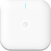
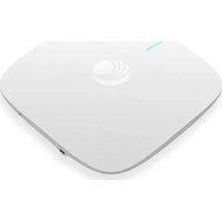
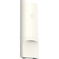

- Reservation of Rights
- Copyrights
- Restrictions
- License Agreements
- High Risk Materials
- Contents
- Contents .3
- About This User Guide...12
- Quick Start - Device Access...18
- Onboarding the Device 25
- Configuring the System...27
- Configuring the Radio 39
- Configuring the Wireless LAN 62
- Configuring the Network 120
- Configuring Access Control...142
- Managing Filters 146
- WIDS/WIPSPremium feature 171
- Configuring Services 176
- Operations 190
- Troubleshoot 192
- Management Access...203
- Mesh 208
- Guest Access Portal - Internal 237
- Guest Access Portal - External 243
- Guest Access - cnMaestro 247
- Auto VLAN 248
- Device Recovery Methods 249
- Command-Line Interface (CLI) 251
- cnMaestro X Assurance...257
- MarketApps 258
- AFC 259
- Glossary 265
- Appendix 267
- Cambium Networks 288
- Overview of Enterprise Wi-Fi AP products
- Intended audience
- Purpose
- Feedback
- Important regulatory information
- Complying with rules for the country of operation
- Caution
- Note
- Canada specific information
- Europe specific information
- Related documents
- New hardware platforms
- Existing hardware platforms
- Warning
- Premium feature list
- Quick Start - Device Access
- Powering up the device
- PoE switches (802.3af/802.3at/802.3bt)
- PoE switches (802.3at)
- PoE adapter
- DC power supply
- Accessing the device
- Device access using default or fallback IP
- Device access using zeroconf IP
- Device access using DHCP IP address
- LED status
- Onboarding the Device
- Overview
- Device onboarding and provisioning
- cnMaestro
- Supported devices and minimum version
- XMS-Cloud
- Configuring the System
- Basic
- Power over Ethernet (PoE) in
- Attention
- Power over Ethernet (PoE) Out port
- Link Layer Discovery Protocol (LLDP)
- Power negotiation
- CLI Configuration
- To enable:
- To disable:
- To list LLDP configuration:
- Request power
- Transmit hold
- Transmit interval
- Management
- Administrator Access
- HTTPS Proxy server configuration
- CLI Configuration:
- Time settings
- Event logging
- SNMP
- Configuring the Radio
- Configuring Radio parameters
- Software-Defined Radio (SDR) capabilities
- Software-Defined Radio
- Note:
- Off Channel Scan (OCS)
- Enhanced Roaming
- BSS Coloring
- Target Wake Time (TWT)
- Receive sensitivity configuration
- Multicast-snooping and Multicast-to-Unicast conversion
- Boot loop detection
- Auto-RF
- Dynamic Channel
- Auto Channel Selection (ACS)
- Dynamic Channel Selection (DCS)
- Dynamic Power
- Auto-RF behavior on device turn on
- Auto-RF Rx Sensitivity
- Configuring Dynamic Channel
- ACS method
- DCS method
- Packet Error Rate (PER)
- Congestion channel switch
- Configuring Dynamic Power
- Radio Configuration
- Basic section
- Channel Scan section
- Configuring the Wireless LAN
- Configuring the WLAN parameters
- Maximum wireless client
- Maximum clients per device
- Maximum clients per SSID
- Maximum clients per SSID per radio
- Opportunistic Wireless Encryption (OWE)
- WLAN-2:
- WLAN VLAN allowed list
- ICMPv6 Router advertisement (RA) unicast conversion
- 802.11k/v
- 802.11k
- 802.11v
- RADIUS server
- Proxy Through Controller
- EAP-FAST support
- Guest Access
- Internal Access Point
- External Hotspot
- Usage Limits
- Scheduled Access
- Access
- Sample DNS-ACL configuration
- Fallback to WLAN VLAN when RADIUS-based MAC authentication fails
- Passpoint
- RADIUS attributes
- Enterprise PSK (ePSK)
- Configuring ePSKs
- ePSK registration for WPA3 clients
- ePSK with WPA3 feature recommendations
- Scenarios while registering clients
- Enabling ePSK registration flow using the AP CLI
- Configuring ePSK registration for WPA3 clients
- Registration flow screenshots
- Click Disconnect.
- Reconnect to the network using the ePSK passphrase that you provided in the Client Registration page earlier.
- Recommended best practices
- Creating a Personal Wi-Fi ePSK
- RADIUS-based ePSK Premium feature
- Configuring RADIUS-based ePSK
- Groupwise Transient Key (GTK) per VLAN
- cnMaestro configuration:
- Dynamic ARP Inspection
- Configuring the Network
- Configuring Network parameters
- IPv4 network parameters
- VLAN
- DHCP Client Options
- DHCP Option 43—Zero-touch onboarding
- DHCP Option 43 format
- Routing and DNS
- Routes
- IPv6 network parameters
- Routing & DNS
- General network parameters
- Ethernet Ports
- Port Control—802.1X Authentication
- DHCP
- Tunnel
- Point-to-Point Protocol over Ethernet (PPPoE)
- VLAN Pool
- Wireless Wide Area Network (WWAN)
- Supported hardware
- Configuring Access Control
- Enabling Access Control Policy
- User Group Policy
- Device Policy
- Managing Filters
- Filter list
- Filters
- Control Windows.
- Configuring filter CLI
- Example:
- Sample configuration
- Device class filter
- Wi-Fi Calling support
- Air cleaner
- Configuration CLI:
- Application control Premium feature
- Deep Packet Inspection (DPI)
- Application control policy
- Risk and productivity
- Selection criteria
- DPI CLI configuration
- Global application policy
- Set per category policy
- Custom Applications X
- Wireless Intrusion Detection Systems (WIDS)
- Wireless flood detection
- Neighbor AP detection
- Rogue APs
- Honeypot APs
- Ad Hoc network detection
- Wired Devices
- Configuring WIDS
- Wireless Intrusion Prevention System (WIPS)
- Configuring Services
- Lightweight Directory Access Protocol (LDAP)
- NAT Logging
- User Groups Premium feature
- User group properties and actions
- User group policies
- Real-Time Location System (RTLS)
- Wi-Fi API
- Bluetooth API
- Sending report
- Bluetooth API data elements
- Stanley AeroScout Premium feature
- Speed Test
- DHCP Option-82
- Bonjour Gateway
- Link Aggregation Control Protocol (LACP)
- Configuration:
- Operations
- Firmware upgrade
- LED Test flashing pattern
- CLI commands:
- Troubleshoot
- Status
- Downloading tech support file
- Logging
- Debug Logs
- Radio Frequency (RF)
- Wi-Fi Analyzer
- Click Start Scan.
- Packet capture
- Performance
- Network Connectivity
- Click Start .
- Remote CLI
- Flash LEDs
- XIRCON tool support
- XIRCON tool support for Linux 1.0.0.40
- Management Access
- Local authentication
- Device configuration
- SSH Key authentication
- SSH Key generation
- Windows
- Linux
- RADIUS authentication
- Mesh
- Deployment scenarios
- Mesh configurable parameters
- Order of Mesh profile configuration
- Mesh Base (MB)
- Mesh Client (MC)
- Mesh Recovery (MR)
- Mesh SNR-threshold
- Mesh Mode
- Mesh ACL
- - RADIUS
- - cnMaestro
- MAC Authentication
- Mesh Auto Detect Backhaul
- Scenario 1
- Scenario 2
- Scenario 3
- Mesh Base
- Mesh Muti-Hop
- Mesh Roaming
- Mesh Base configuration
- Mesh Client configuration
- Mesh link-Sample configuration
- VLAN 1 as the management interface
- Non-VLAN 1 as the management interface
- Typical use-cases
- Additional mesh topology supported
- Wired devices behind mesh client AP
- Guest Access Portal - Internal
- Introduction
- Configurable parameters
- Access policy
- Click through
- Splash page
- Title
- Terms and conditions
- Logo
- Background image
- Redirect parameters
- Redirect hostname
- Success action
- Redirect
- Redirect Mode
- Success message
- Timeout
- Session
- Inactivity
- Whitelist
- Configuration examples
- Access Policy - Clickthrough
- Guest Access Portal - External
- Clickthrough
- WISPr
- External portal post through cnMaestro
- External portal type
- Standard
- Guest Access - cnMaestro
- Auto VLAN
- Syntax:
- Device Recovery Methods
- Factory reset via 'RESET' button
- Boot partition change via power cycle
- Disable factory Reset Button
- Command-Line Interface (CLI)
- Show commands
- Service commands
- Service show
- Service system
- MarketApps
- Target audience
- Benefits
- AFC
- Supported AP firmware version
- Supported cnMaestro version
- Supported countries
- AFC 6 GHz frequency range support
- Prerequisites for AFC Operation
- AFC Operation
- AP onboarding and registration
- cnMaestro contacts AFC server
- AP sends request to obtain AFC token
- AP waits for the GPS lock
- AP sends Spectrum Availability Request to AFC server
- AP activates 6 GHz radio based on AFC response
- Periodic Spectrum Validity Check
- Reboot or Failure Scenarios
- AFC information in dashboard
- GPS configuration CLIs
- AFC Troubleshooting
- Verify GPS information received by the AP
- Verify AFC server connection status and information
- AFC events
- Appendix
- Supported RADIUS Attributes
- WISPr VSAs (Vendor ID: 14122)
- Cambium VSAs (Vendor ID: 17713)
- Standard RADIUS attributes
- RADIUS attributes in authentication and accounting packets with WPA2-Enterprise security
- Supported CoA messages
- Supported DFS channels
- Supported 6 GHz countries
- Priority order for parameters
- Reasons for AP restarting
- Best practices for wireless clients seamless roaming across APs
- External network recommendations
- AP WLAN profile configuration recommendations
- AP group configuration recommendations
- Cambium Networks
- Cambium Networks™
Brand : Cambium Networks
Model : XE3-4
Category : Access Point