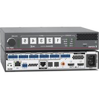
SSP 200 - Audio processor Extron - Free user manual and instructions
Find the device manual for free SSP 200 Extron in PDF.


| Product Type | Surround Sound Processor |
| Form Factor | Half-rack 1U, 8.7" (22.1 cm) wide x 1.7" (4.3 cm) high x 6.0" (15.2 cm) deep |
| Weight | 2.5 lbs (1.1 kg) |
| Power Supply | 100-240 VAC, 50/60 Hz, IEC power input; typical consumption 15 W |
| Audio Inputs | 1 HDMI, 1 S/PDIF coaxial, 2 S/PDIF optical (TOSLINK), 1 balanced/unbalanced analog (6-pin captive screw) |
| Audio Outputs | 10 balanced/unbalanced analog (6-pin captive screw) for 5.1, 7.1, 5.1.2, 7.1.2, 5.1.4, or 7.1.4; plus EXP expansion (14+2 channels) |
| Supported Audio Formats | Dolby Atmos, Dolby TrueHD, Dolby Digital Plus, Dolby Digital, DTS:X, DTS-HD Master Audio, DTS-HD High Resolution, DTS-ES, DTS 96/24, PCM up to 7.1; up to 192 kHz sampling |
| Video Support | HDMI 2.0b pass-through up to 4K/60 @ 4:4:4, 18 Gbps, HDR, Deep Color up to 12-bit, 3D |
| Control Interfaces | Front USB mini-B config port, rear RS-232 (3-pole captive screw), rear LAN (RJ-45), front panel buttons with LED indication |
| Audio Processing | Auto format detection, bass management with crossover 40-250 Hz, parametric EQ (9 bands per output), lip sync up to 300 ms per input, test signals (pink noise, Dolby noise) |
| Speaker Configurations | 5.1, 7.1, 5.1.2, 7.1.2, 5.1.4, 7.1.4 (with EXP expansion for 7.1.4) |
| Listening Modes | Auto, Stereo, Mono, Stereo to All, Mono to All, Dolby Surround upmixer, DTS Neural:X upmixer |
| EDID Management | Extron EDID Minder; import/export EDID, assign per input |
| Security | Front panel lockout (executive mode) with 3 levels; password protection for web and control access |
| Mounting | Tabletop (rubber feet), rack mount (optional kit), under-desk mount (optional kit) |
| Operating Temperature | 32°F to 122°F (0°C to 50°C) |
| Compliance | FCC Class A, CE, RoHS; use shielded I/O cables for compliance |
| Maintenance | Clean with dry cloth; no user-serviceable parts; internal battery not replaceable user, return to Extron |
| Warranty | 3 years parts and labor (Extron standard warranty) |
| Spare Parts & Repairability | Not user-serviceable; contact Extron for repairs; return with RA number |
Frequently Asked Questions - SSP 200 Extron
User questions about SSP 200 Extron
0 question about this device. Answer the ones you know or ask your own.
Ask a new question about this device
Download the instructions for your Audio processor in PDF format for free! Find your manual SSP 200 - Extron and take your electronic device back in hand. On this page are published all the documents necessary for the use of your device. SSP 200 by Extron.
USER MANUAL SSP 200 Extron
Surround Sound Processor
Extron
68-3281-01 Rev. A
02 21
Safety Instructions
Safety Instructions • English

WARNING: This symbol, ⚠, when used on the product, is intended to alert the user of the presence of uninsulated dangerous voltage within the product's enclosure that may present a risk of electric shock.
ATTENTION: This symbol, ⚠, when used on the product, is intended to alert the user of important operating and maintenance (servicing) instructions in the literature provided with the equipment.
For information on safety guidelines, regulatory compliances, EMI/EMF compatibility, accessibility, and related topics, see the Extron Safety and Regulatory Compliance Guide, part number 68-290-01, on the Extron website, www.extron.com.
© 2021 Extron. All rights reserved.
Trademarks
All trademarks mentioned in this guide are the properties of their respective owners.
The following registered trademarks ^® , registered service marks ^SM , and trademarks ^TM are the property of RGB Systems, Inc. or Extron (see the current list of trademarks on the Terms of Use page at www.extron.com):
| Registered Trademarks (®) |
| Extron, Cable Cubby, ControlScript, CrossPoint, DTP, eBUS, EDID Manager, EDID Minder, Flat Field, FlexOS, Glitch Free, Global Configurator, Global Scripter, GlobalViewer, Hideaway, HyperLane, IP Intercom, IP Link, Key Minder, LinkLicense, LockIt, MediaLink, MediaPort, NAV, NetPA, PlenumVault, PoleVault, PowerCage, PURE3, Quantum, Show Me, SoundField, SpeedMount, SpeedSwitch, StudioStation, System INTEGRATOR, TeamWork, TouchLink, V-Lock, VideoLounge, VN-Matrix, VoiceLift, WallVault, WindoWall, XPA, XTP, XTP Systems, and ZipClip |
| Registered Service Mark ^(SM) : S3 Service Support Solutions |
| Trademarks ^(TM) |
| AAP, AFL (Accu-RATE Frame Lock), ADSP (Advanced Digital Sync Processing), CableCover, CDRS (Class D Ripple Suppression), Codec Connect, DDSP (Digital Display Sync Processing), DMI (Dynamic Motion Interpolation), Driver Configurator, DSP Configurator, DSVP (Digital Sync Validation Processing), eLink, EQIP, Everlast, FastBite, Flex55, FOX, FOXBOX, IP Intercom HelpDesk, MAAP, MicroDigital, Opti-Torque, PendantConnect, ProDSP, QS-FPC (QuickSwitch Front Panel Controller), Room Agent, Scope-Trigger, ShareLink, SIS, Simple Instruction Set, Skew-Free, SpeedNav, Triple-Action Switching, True4K, Vector ^TM 4K , WebShare, XTRA, and ZipCaddy |
FCC Class A Notice
This equipment has been tested and found to comply with the limits for a Class A digital device, pursuant to part 15 of the FCC rules. The Class A limits provide reasonable protection against harmful interference when the equipment is operated in a commercial environment. This equipment generates, uses, and can radiate radio frequency energy and, if not installed and used in accordance with the instruction manual, may cause harmful interference to radio communications. Operation of this equipment in a residential area is likely to cause interference. This interference must be corrected at the expense of the user.
ATTENTION:
- This unit was tested with shielded I/O cables on the peripheral devices. Shielded cables must be used to ensure compliance with FCC emissions limits.
- For more information on safety guidelines, regulatory compliances, EMI/EMF compatibility, accessibility, and related topics, see the Extron Safety and Regulatory Compliance Guide on the Extron website.
Battery Notice
This product contains a battery. Do not open the unit to replace the battery. If the battery needs replacing, return the entire unit to Extron (for the correct address, see the Extron Warranty section on the last page of this guide).
CAUTION: Risk of explosion. Do not replace the battery with an incorrect type. Dispose of used batteries according to the instructions.
Conventions Used in this Guide
Notifications
The following notifications are used in this guide:

WARNING: Potential risk of severe injury or death.
CAUTION: Risk of minor personal injury.
NOTE: A note draws attention to important information.
TIP: A tip provides a suggestion to make working with the application easier.
Software Commands
Commands are written in the fonts shown here:
^AR Merge Scene,,Op1 scene 1,1^B 51^W^C
[01] R000400300004000080000600 [02] 35 [17] [03]
Esc X1 * X17 * X20 * X23 * X21 CE ←
NOTE: For commands and examples of computer or device responses mentioned in this guide, the character “θ” is used for the number zero and “O” is the capital letter “o.”
Computer responses and directory paths that do not have variables are written in the font shown here:
Reply from 208.132.180.48: bytes=32 times=2ms TTL=32
C:\Program Files\Extron
Variables are written in slanted form as shown here:
ping xxx.xxx.xxx.xxx -t
SOH R Data STX Command ETB ETX
Selectable items, such as menu names, menu options, buttons, tabs, and field names are written in the font shown here:
From the File menu, select New.
Click the OK button.
Specifications Availability
Product specifications are available on the Extron website, www.extron.com.
Extron Glossary of Terms
A glossary of terms is available at http://www.extron.com/technology/glossary.aspx.
Contents
Introduction ...... 1
About the SSP 200....1
SSP 200 Features 2
Application Diagrams....3
Mounting 5
Tabletop Placement 5
Rack Mounting 5
Under-desk Mounting 5
Panel Features......6
Rear Panel Features 6
Securing an HDMI Connector....10
Front Panel Features....11
Source Format....11
Input Selection....12
Volume Adjustment....13
Analog Input Gain Level 13
System Reset 14
Front Panel Security Lockout (Executive Mode) 15
Connecting to the USB Port 16
Speaker Setup 18
Speaker Placement 18
Back Speakers....21
Bass Management 21
Speaker Settings 21
Speaker Delay Settings.... 22
Test Signals 22
Output Channel Trim Settings 23
Listening Mode Settings 23
Equalization....23
Reference 24
Source Formats....24
Dolby Digital Source Formats....25
DTS Source Formats (DTS)....25
PCM Digital Source Format (PCM)....26
2-Channel Source Format (2CH)....26
Sampling Frequency 27
Listening Mode Options and Usage 27
Listening Mode Options....27
Product Configuration Software ...... 29
Downloading PCS from the Extron Website......29
Using PCS Software 30
Connecting to the SSP 200 30
Main Menu 31
I/O Panel 32
Input/Output Config....32
EDID Minder 35
Audio Config....41
General Settings 50
Device Menu.... 57
Reset Device 57
PCS Help File 58
Updating Firmware Using PCS 58
Downloading the SSP 200 Firmware....58
Loading the Firmware to the SSP 200 ..... 59
SIS Configuration and Control ......62
Connection Options....62
RS-232 Port 62
Front Panel Configuration Port....62
Ethernet (LAN) Port....63
Verbose Mode 64
Host-to-device Communications 64
Password Information....64
Error Responses....65
Using the Command and Response Tables ..... 65
Symbol Definitions....65
Command and Response Tables....69
Internal Web Page 80
Overview of the Internal Web Page 80
Accessing the Internal Web Page 80
Web Page Components 81
Device Info....81
Device Status 82
Network Settings....83
Inputs 84
Outputs 84
RS-232....85
Roles and Permissions 85
Firmware 86
Introduction
This manual explains how to mount, install, and configure the Extron SSP 200 Surround Sound Processor.
Unless otherwise specified, references in this manual to the SSP 200, "SSP", "surround sound processor", or "processor" all refer to the SSP 200 device.
About the SSP 200
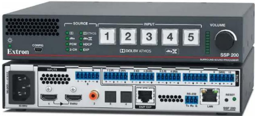
The SSP 200 is a high-performance digital audio surround sound processor in a half-rack, 1U form-factor. The SSP 200 automatically decodes Dolby® and DTS® formats from digital sources to discrete audio outputs.
The SSP 200 is compatible with all Extron (and non-Extron) products that accommodate analog balanced or unbalanced line level inputs. EXP expansion input connectivity allows the SSP 200 to integrate directly with EXP-enabled Extron products, such as the DMP Plus series and AXI 016 interface.
The SSP 200 can decode and process licensed, branded digital source formats from Dolby Digital and DTS, in their originally encoded formats. These include:
• Dolby Digital 2/0 • DTS Digital Surround
• Dolby Digital 2/0 Surround • DTS 96/24
• Dolby Digital 5.1 • DTS-ES
• Dolby Digital Surround EX™
• Dolby Digital Plus • DTS-ES Discrete 6.1
• Dolby Digital TrueHD • DTS-HD High Resolution Audio
• Dolby Atmos • DTS-HD Master Audio
• DTS 2-channel
NOTES:
- Dolby, Dolby Atmos, and the double-D symbol are trademarks of Dolby Laboratories. Manufactured under license from Dolby Laboratories.
- For DTS patents, see http://patents.dts.com. Manufactured under license from DTS, Inc. DTS, the Symbol, DTS and the Symbol together, DTS:X, and the DTS:X logo are registered trademarks or trademarks of DTS, Inc. in the United States and/or other countries. © DTS, Inc. All Rights Reserved.
SSP 200 Features
- Supports the latest immersive 3D audio formats as well as legacy surround formats:
- Dolby Atmos • DTS:X
• Dolby TrueHD • DTS-HD Master Audio
• Dolby Digital Plus • DTS-HD High Resolution Audio
• Dolby Surround • DTS Neural:X
• Dolby Digital EX • DTS-ES
• Dolby Digital • DTS 96/24
• Dolby Pro Logic IIx • DTS NEO:6 -
Dolby Pro Logic II
-
Automatic surround sound format detection and decoding — Automatically detects the format of the incoming audio signal, applies the necessary decoding, and then sends signals to the appropriate outputs.
- Supports video resolutions up to 4K/60 @ 4:4:4 — Supports video signal passed through unaltered.
- Upmix listening mode converts source program into immersive or standard surround playback — Converts from any input format to any selected higher output channel count format.
- Integrated test signals for calibration and connectivity validation during set up.
- Pink noise generator to calibrate a speaker interaction within the environment.
- Dolby Noise: bandpass noise generator to balance speaker levels.
- External option: Can use test disc, or other calibration sources for specific decoding outputs.
- EXP expansion output port — Provides easy I/O connection to an Extron DMP Plus Series audio DSP processor. This allows for a higher output count and seamless integration with all DMP capabilities including Dante transport.
- Lip Sync Offset — 0 ms to 300 ms per input.
• Supports commonly used speaker output configurations:
• 5.1, 7.1, and 5.1.2 with stereo downmix on outputs 9 and 10.
• 5.1.4, 7.1.2, and 7.1.4 with stereo downmix on the EXP expansion bus.
- EXP expansion bus connection to a DMP Plus Series processor is required for 7.1.4.
- Supported HDMI 2.0b specification features include data rates up to 18 Gbps, HDR, Deep Color up to 12-bit, 3D, and HD lossless audio formats.
• HDMI Loop Output supports Downmix:
- Local monitor output audio modes.
- Original Audio – Multichannel or two channel.
- Stereo Downmix – Independent of speaker output configuration.
- No Audio.
- PCM input formats:
- Uncompressed stereo digital audio signals can be processed from the HDMI, TOSLINK, or Coaxial inputs.
- Uncompressed 7.1 digital audio signals can be processed from the HDMI inputs.
- Front panel input selection with LED indication.
• Supports 802.1X Authentication — Provides support for IEEE 802.1X authentication standard for port-based Network Access Control.
Application Diagrams
flowchart
graph TD
    A["Extron SF 10C SUB Subwoofer"] -->|Ch. 1 & 2 Bridged| B["Extron XPA 4002 Power Amplifier"]
    B -->|Audio| C["Extron SSP 200 Surround Sound Processor"]
    C -->|Audio| D["HDMI Source"]
    C -->|Audio| E["Extron SM 28 Speakers"]
    C -->|Audio| F["Extron XPA U 1004 Power Amplifier"]
    C -->|Audio| G["Extron XPA U 1002 Power Amplifier"]
    C -->|LHF, RHF, LHB, RHB| H["LHF, RHF, LHB, RHB"]
    C -->|Audio| I["HDMI"]
    C --> J["Extron SF 26CT Two-Way Ceiling Speakers"]
    C --> K["Extron SM 26 Speakers"]
    style A fill:#f9f,stroke:#333
    style B fill:#ccf,stroke:#333
    style C fill:#cfc,stroke:#333
    style D fill:#fcc,stroke:#333
    style E fill:#cff,stroke:#333
    style F fill:#ffc,stroke:#333
    style G fill:#fcc,stroke:#333
    style H fill:#fff,stroke:#333
    style I fill:#fff,stroke:#333
    style J fill:#fff,stroke:#333
    style K fill:#fff,stroke:#333
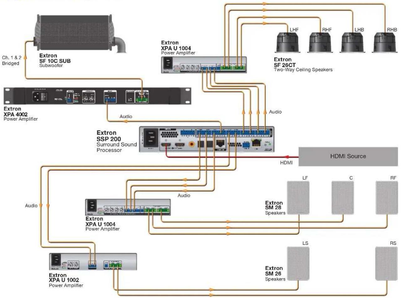
Figure 1. Typical Application with 5.1.4 Speaker Setup

flowchart
graph TD
    A["HDMI Source"] -->|HDMI| B["Extron SSP 200 Surround Sound Processor"]
    B --> C["Extron XPA U 1004 Power Amplifier"]
    C --> D["Extron SM 26 Speakers"]
    C --> E["Extron SM 28 Speakers"]
    C --> F["Extron XPA U 1004 Power Amplifier"]
    F --> G["Extron SF 10C Sub Subwoofer"]
    G --> H["Ch. 1 & 2 Bridged"]
    H --> I["Extron XPA 4002 Power Amplifier"]
    I --> J["Audio"]
    J --> K["Extron XPA U 1004 Power Amplifier"]
    K --> L["Extron SM 26 Speakers"]
    K --> M["Extron SM 28 Speakers"]
    K --> N["Extron SM 28 Speakers"]
    K --> O["LS"]
    K --> P["RS"]
    K --> Q["LB"]
    K --> R["RB"]
Figure 2. Typical Application with 7.1 Speaker Setup
Mounting
The SSP 200 can be set on a table, mounted on a rack shelf, or mounted under a desk, podium, or table.
ATTENTION:
Attach the four provided rubber feet to the bottom of the unit and place it in any convenient location.
Rack Mounting
See the Extron website for a list of optional rack mounting kits that are suitable for the SSP 200. Follow the instructions provided with the kit.
UL Guidelines for Rack Mounting
The following Underwriters Laboratories (UL) guidelines are relevant to the safe installation of these products in a rack:
- Elevated operating ambient temperature — If the unit is installed in a closed or multi-unit rack assembly, the operating ambient temperature of the rack environment may be greater than room ambient temperature. Therefore, install the equipment in an environment compatible with the maximum ambient temperature (Tma: +122°F, +50°C) specified by Extron.
- Reduced air flow — Install the equipment in the rack so that the equipment gets adequate air flow for safe operation.
- Mechanical loading — Mount the equipment in the rack so that uneven mechanical loading does not create a hazardous condition.
- Circuit overloading — Connect the equipment to the supply circuit and consider the effect that circuit overloading might have on overcurrent protection and supply wiring. Appropriate consideration of the equipment nameplate ratings should be used when addressing this concern.
- Reliable earthing (grounding) — Maintain reliable grounding of rack-mounted equipment. Pay particular attention to supply connections other than direct connections to the branch circuit (such as the use of power strips).
Under-desk Mounting
See the Extron website to find the optional under-desk mounting kit that is suitable for the SSP 200. Follow the instructions provided with the kit.
Panel Features
This section describes:
- Rear Panel Features
- Front Panel Features
Rear Panel Features

Figure 3. SSP 200 Rear Panel Features
A AC power input
E LAN port
B Audio inputs
F Reset button
© DMP expansion port
G Status LED
D RS-232 port
H Analog outputs
A AC power input — Use an IEC power cable to connect the processor to a 100 - 240 VAC, 50 - 60 Hz, power source.
B Audio inputs — The SSP 200 accepts four digital inputs and one analog input (see figure 4).

Figure 4. SSP 200 Audio Inputs
- Input 1 accepts digital signals through an HDMI cable (see Securing an HDMI Connector on page 10). The THRU connection passes the original HDMI video signal out, unaltered, to another device. Audio passed to the THRU connection is configurable (see Input/Output Config on page 32).
- Input 2 accepts digital signals through a S/PDIF coaxial cable.
- Inputs 3 and 4 accept digital signals through S/PDIF optical (TOSLINK) cables.
- Input 5 accepts a balanced or unbalanced, stereo or mono, analog input through a 6-pole captive screw connector. Figure 5 shows the correct wiring for different analog input signals using either 3-pole or 6-pole connectors.

Figure 5. Analog Input (Input 5) Wiring
ATTENTION:
C DMP Expansion port — This proprietary Extron DMP Expansion port provides 14 output channels and 2 input channels (for use as a stereo input) for exclusive use with EXP-compatible Extron devices. The first 10 EXP output channels are duplicates of the 10 analog outputs (except for Downmix Left and Right, which always appear on EXP outputs 15 and 16). Two additional EXP Outputs are available for 7.1.4 speaker configurations.
The EXP port is limited to a sample rate of 48 kHz at 24-bit depth per channel. High sample rate codecs (such as DTS 96/24 at 96 kHz and Dolby TrueHD at a maximum 192 kHz are first resampled to 48 kHz before transport via the EXP bus.
RS-232 port — The SSP 200 can be configured with Extron Product Configuration Software (PCS) or Simple Instruction Set (SIS) commands using this 3-pole captive screw connector (see Product Configuration Software starting on page 29 and SIS Configuration and Control starting on page 62)

flowchart
graph LR
    A["RS-232 Device"] -->|Bidirectional| B["Remote RS-232"]
    A -->|Transmit (Tx)| C["Transmit (Tx)"]
    A -->|Receive (Rx)| D["Receive (Rx)"]
    A -->|Ground(Gnd)| E["Ground(Gnd)"]
    B --> F["Tx Rx G"]
    B --> G["REMOTE"]
Figure 6. RS-232 Wiring Example
E LAN port — RJ-45 connector allows the SSP 200 to be connected to a Local Area Network (LAN) connection for control and configuration. As with the RS-232 and USB connections, the device can be controlled using SIS commands through an external control system or via PCS in order to configure the device and receive status information as required.
The Ethernet cable can be terminated as a straight-through cable or a crossover cable and must be properly terminated for your application (see figure 7 for wiring information).
- Crossover cable — Direct connection between the computer and the SSP 200.
- Patch (straight) cable — Connection of the SSP 200 to an Ethernet LAN.

| Crossover Cable (for direct connection to a PC) | |
| End 1 End 2 Pin Wire Color Pin | Wire Color |
| 1 white-orange 1 | white-green |
| 2 orange 2 | green |
| 3 white-green 3 | white-orange |
| 4 blue 4 | blue |
| 5 white-blue 5 | white-blue |
| 6 green 6 | orange |
| 7 white-brown 7 white-brown | |
| 8 brown 8 | brown |
| Straight-through Cable (for connection to a switch, hub, or router) | |
| End 1 End 2 Pin Wire Color Pin | Wire Color |
| 1 white-orange 1 white-orange | |
| 2 orange 2 orange | |
| 3 white-green 3 white-green | |
| 4 blue 4 blue | |
| 5 white-blue 5 white-blue | |
| 6 green 6 green | |
| 7 white-brown 7 white-brown | |
| 8 brown 8 brown | |
T568B T568A T568B T568B
A cable that is wired as TIA/EIA T568A at one end and T568B at the other (Tx and Rx pairs reversed) is a "crossover" cable.
A cable wired the same at both ends is called a "straight-through" cable because no pin/pair assignments are swapped.
Figure 7. RJ-45 Ethernet Connector Pin Assignment
F Reset button — The Reset button initiates various levels of soft resets, which restore various tiers of SSP 200 settings to their defaults (see System Reset on page 14). Use a pointed stylus or small screwdriver (such as an Extron Tweeker) to press the internal button.
Status LED — The Status LED is used in conjunction with the Reset button (see System Reset on page 14).
Analog outputs (see figure 8) — Outputs are balanced or unbalanced line level analog signals that feed into multichannel amplifiers for configurations up to 7.1.2 or 5.1.4 surround sound. For more information, see Speaker Placement on page 18.

Figure 8. Analog Audio Outputs
Individual output settings are configured through PCS (see Speaker Placement) or SIS commands (Layouts and Speakers on page 78). Refer to the following table for output designations.
| Numbers Abbreviations Channel Description | |
| 1 LF Left Front | |
| 2 RF Right Front | |
| 3 C Center | |
| 4 SUB Subwoofer (Mono) | |
| 5 LS Left Surround | |
| 6 RS Right Surround | |
| 7 see note below | |
| 8 see note below | |
| 9 see note below | |
| 10 see note below | |
NOTES:
- Numbers 7 through 10 are configurable as Back, Height, or Downmix using PCS.
- The default configuration is 7.1 with Downmix on numbers 9 and 10 enabled.
For information about speaker configuration and output formats, see Listening Mode Options and Usage on page 27. See figure 9 for audio output connector wiring.

Figure 9. Audio Output Wiring
ATTENTION:
- For unbalanced audio, connect the sleeves to the ground contact. DO NOT connect the sleeves to the negative (−) contacts.
- Pour l'audio asymétrique, connectez les manchons au contact au sol. Ne PAS connecter les manchons aux contacts négatifs (-).
Securing an HDMI Connector
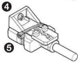
Follow these instructions to secure the HMDI connectors to the processor with the LockIt HDMI lacing bracket provided:
① Plug the HDMI cable into the processor rear panel connection.
② Loosen the HDMI connection mounting screw from the panel enough to allow the LockIt lacing bracket to be placed over it. The screw does not have to be removed.
3 Place the LockIt lacing bracket on the screw and against the HDMI connector, then tighten the screw to secure the bracket.
ATTENTION:
natural_image
Technical line drawing of a mechanical device with labeled parts (no text or symbols present)4 Loosely place the included tie wrap around the HDMI connector and the LockIt lacing bracket as shown.
⑤ While holding the connector securely against the lacing bracket, tighten the tie wrap, then remove any excess length.
Front Panel Features

Figure 10. SSP 200 Front Panel Features
A Status LED
D Input Selections
B Configuration port
Volume Adjustment
© Input Source format indicators
A Status LED — This LED indicates the current power and boot status of the SSP 200.
B Configuration port — The SSP 200 can be configured via PCS or by using Extron Simple Instruction Set (SIS) commands via this USB mini-B port or via the LAN and RS-232 ports on the rear panel (see SIS Configuration and Control starting on page 62). In addition, this configuration port is used for firmware updates from a PC.
NOTE: The front panel configuration port, the rear panel RS-232 port, and the rear panel LAN port can all be used at the same time. No connection has precedence. The SSP 200 responds to commands in the order received.
Source Format
C Input Source format indicators — The bank of eight LEDs identify the format of the audio input (see Source Formats starting on page 24).
• ☐: Dolby source material
• DTS: DTS source material
• PCM: 2-channel uncompressed digital source format up to 7.1 multi-channel
NOTES:
- A digital signal that does not have a supported sampling rate or is compressed PCM is considered an unrecognized signal and is muted.
- When a media player is paused during playback, the SSP 200 may or may not continue to receive source format information from the player. Some players continue to send the same source format information in a loop, allowing the SSP 200 to retain the previous settings. Other players completely disconnect the signal from the SSP 200 (unlocked state) so that the active input appears as if there is no connection present. The remainder of players change the source output to PCM without an actual signal being sent (digital silence). During digital silence, the PCM LED lights but the 2-CH source LED does not.
• 2-Channel (2-CH):
- Any source coming through analog input 5.
- If a 2-Channel PCM digital signal is present on any of the digital inputs, both the PCM and the 2-CH LEDs light.
- If a Dolby Digital 2/0 or Dolby Digital 2/0 Surround source is present, both the ☐ and the 2-CH LEDs light.
- If a DTS 2-Channel source format is present, both the DTS and 2-CH LEDs light.
• ATMOS: Dolby Atmos source material
• DTS:X: DTS:X source material (HDMI only)
• HDCP: HDMI source material (HDMI only)
- EXP: Valid EXP connection. Blinks when the assigned EXP input is selected.
Input Selection
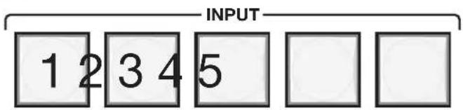
Figure 11. SSP 200 Input Selection Switches
D Input selection buttons — Push one of the buttons to select between the five audio inputs. When a button is selected, the button lights green indicating it is the active input. For digital inputs 1 through 4, the button turns amber when it is selected and the digital clock signal has not been detected.
The Input 5 button turns red when the analog input is clipping. The Analog Input Gain Level can be adjusted with the volume adjustment knob (see page 13).
The SSP accepts four digital inputs and one analog input (see Rear Panel Features on page 6):
- Input 1 accepts digital signals through an HDMI cable.
- Input 2 accepts digital signals through a S/PDIF coaxial cable.
- Inputs 3 and 4 accepts digital signals through S/PDIF optical cables. The SSP 200 supports TOSLINK or TOSLINK-compatible optical connectors that conform to IEC-958, S/PDIF standards.
All four digital inputs accept 16- to 24-bit PCM audio at 32 kHz, 44.1 kHz, 48 kHz, 88.2 kHz, 96 kHz, and 192 kHz sample rates. They support Dolby Digital and DTS source formats.
- Input 5 accepts a balanced or unbalanced analog input through a 6-pin captive screw connector. The unit can be configured to accept:
- A stereo signal
• A mono signal (see Listening Mode Options on page 27)
The input can also be selected using PCS (see Product Configuration Software on page 29) and SIS commands (see SIS Configuration and Control on page 62).
Volume Adjustment
E Volume control and LED bar — Use the rotary encoder to adjust the output volume from 0% to 100%. The default setting is 80%.
As the volume increases or decreases, the LED bar lights to indicate the current volume setting (see the table below). As the volume is increased or decreased, the top LED flashes.
If the audio is muted using PCS or SIS, the entire LED bar blinks to indicate a muted state. The LEDs return to their previous state when the audio is unmuted.
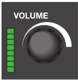
Figure 12. Volume Control and LED Bar
| Volume steps for each LED LEDs lit | |
| 96% to 100% All 8 LEDs on | |
| 91% to 95% Bottom 7 | LEDs on |
| 86% to 90% Bottom 6 | LEDs on |
| 81% to 85% Bottom 5 | LEDs on |
| 71% to 80% Bottom 4 | LEDs on |
| 51% to 70% Bottom 3 | LEDs on |
| 31% to 50% Bottom 2 | LEDs on |
| 1% to 30% Bottom LED on | |
| 0% All LEDs flashing | |
The volume can also be controlled using SIS (see Volume on page 77).
Analog Input Gain Level
Alternatively, the rotary encoder controls the gain level of the analog signal on Input 5. Analog input gain is adjustable from -18 dB to +24 dB.
To adjust input gain, press and hold the Input 5 button, then turn the rotary encoder to increase or decrease the gain level of the input signal (see figure 13 on the next page).
When the Input 5 button is released, the input gain level control is deactivated. All active (input level) LEDs in the LED array bar deactivate momentarily, and then re-activate to display the current volume setting.

Figure 13. Analog Gain Control
NOTES:
- If the gain level is too high, clipping may occur. When clipping occurs, the Input 5 button lights red.
- When using Mono or Mono to All listening mode, the left and right signals are summed (in the digital domain), which can cause a boost in level up to 6 dB. This type of clipping does not cause the clip indicator LED to light but is audible. If using a mono mode, it is recommended that the input gain be reduced by 9 dB to prevent clipping from occurring.
While the Input 5 button is held down, the LED bar lights from the bottom up to indicate the current gain level (see table below).
| Gain steps for each LED LEDs lit | |
| 19 dB to 24 dB All 8 LEDs on | |
| 13 dB to 18 dB Bottom 7 LEDs on | |
| 7 dB to 12 dB Bottom 6 LEDs on | |
| 1 dB to 6 dB Bottom 5 LEDs on | |
| -5 dB to 0 dB Bottom 4 LEDs on | |
| -11 dB to -6 dB Bottom 3 LEDs on | |
| -17 dB to -12 dB Bottom 2 LEDs on | |
| -18 dB | Bottom LED on |
System Reset
The rear panel has a recessed Reset button that initiates various levels of soft resets restoring various tiers of SSP 200 settings to their defaults. For different reset levels, press and hold the button while the SSP 200 is running. Use a pointed stylus or small screwdriver (such as an Extron Tweeker) to press the button.
The following Reset Modes Summary table provides a list of the available reset modes, how to activate them, and the result of that activation.
NOTES:
- The reset modes listed on the next page close all open IP and Telnet connections, as well as close all sockets.
- The factory configured passwords for all accounts on this device have been set to the device serial number. Passwords are case sensitive. If the SSP 200 is reset, the passwords revert to the default, which is extron. A new password would need to be configured to secure the device.
| Reset Modes Summary | ||
| Mode | Activation Result | |
| 1 | Hold in the recessed Reset button while applying power to the device. | Restores the factory-installed firmware.Maintains all user settings (audio adjustments, IP settings, and so on). |
| 4 | Hold in the Reset button until the Reset LED blinks twice (once after approximately 3 seconds and again after 6 seconds). Then, within 1 second press Reset momentarily (for less than 1 second). | Sets the IP address, subnet address, and gateway address to the factory defaults.Sets port mapping to the factory default.Turns DHCP off.Turn event scripts off.The Reset LED blinks four times in quick succession during the reset. |
| 5 | Hold in the Reset button until the Reset LED blinks three times (once after approximately 3 seconds, again after 6 seconds, and then again after 9 seconds); then within 1 second press Reset momentarily (for less than 1 second). | Performs a complete reset to factory defaults. The password reverts toextron.The Reset LED blinks four times in quick succession during the reset. |
Full system resets can also be performed using SIS commands (see Resets on page 78).
Front Panel Security Lockout (Executive Mode)
When the front panel is locked, the user cannot make any input changes from the front panel. If the user attempts to make changes with the front panel locked out, all the input button LEDs flash simultaneously. The lockout does not block changes made using SIS commands or PCS. There are three lockout modes available:
- Mode 1 — All front panel controls are locked. No adjustments can be made.
- Mode 2 — All front panel controls are locked except for volume control. This allows the volume to be adjusted, without the ability to change inputs.
- Mode 3 — All front controls are locked, except for input selection buttons.
This feature can only be set using SIS commands (see SIS Configuration and Control on page 62) or PCS (see Front Panel Lockout (Executive Mode) on page 52).
Connecting to the USB Port
Use the USB mini-B port on the front panel to connect the processor to a host computer to configure the unit with PCS or SIS commands.
- Connect a USB A to mini-B cable between the front panel USB CONFIG port and a USB port on the PC (see figure 14).

Figure 14. Connecting a PC to the SSP 200 Front Panel USB Port
If this is the first time the SSP 200 has been connected to the PC, the Found New Hardware Wizard opens (see figure 15).
The first screen offers to connect to Windows Update to search the web for the appropriate driver needed for the USB port to communicate with the SSP 200. This is not necessary if the USB driver is already on your PC.

Figure 15. Found New Hardware Wizard Opening Screen
- Click on the appropriate radio button (see figure 15).
- Select the Yes, this time only radio button (①) if you want your computer to connect to Windows Update only this one time.
- Select Yes, now and every time I connect a device (see figure 15, ②, on the previous page) if you want the computer to automatically connect to Windows Update to search the web every time the processor is connected to this USB port.
- Select No, not this time (3) if you do not want the computer to connect to Windows Update to search the web at this time (for example, if the driver is already on your computer).
3. Click Next ( 4).
The next screen of the Wizard opens:
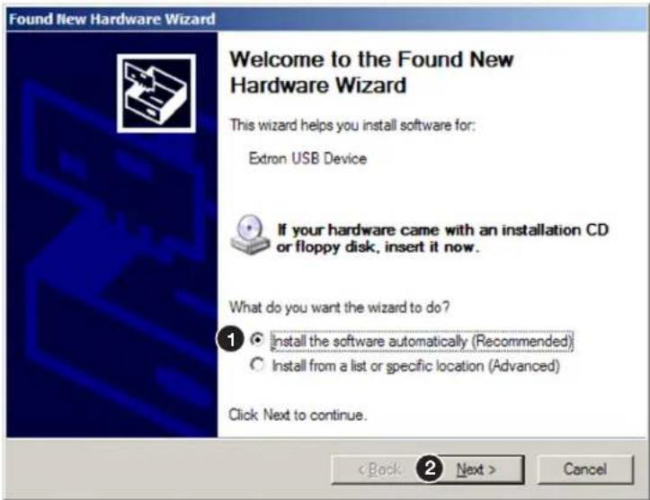
Figure 16. Installing the Software Automatically
-
Select the Install the software automatically (Recommended) radio button (see figure 16, ①).
-
Click Next (②).
NOTE: You do not need to insert a disc.
The PC locates the driver needed and installs it in the correct location on the hard drive.
- When the Completed screen appears, click Finish to close the wizard.
NOTE: The wizard opens only on the first occasion you connect the SSP 200 to that USB port. The wizard reappears if you connect the unit to a different USB port or if you connect a different piece of equipment, requiring a different driver, to the same USB port.
- Configure the processor as desired using SIS commands (see SIS Configuration and Control starting on page 62) or PCS (see Using PCS Software starting on page 30).
Speaker Setup
This section provides background information about arranging speakers in a room and the settings that can be adjusted by the Product Configuration Software (PCS). Extron recommends that the PCS is used to make configuration changes to the SSP 200 (see Product Configuration Software starting on page 29). Topics in this section include:
- Speaker Placement
- Back Speakers
- Bass Management
• Speaker Delay Settings - Test Signals
• Output Channel Trim Settings - Listening Mode Settings
- Equalization
Speaker Placement
The following figures show the recommended speaker placement, relative to the listener, for some of the most common speaker configurations.
Speaker Abbreviations
| Abbreviations Channel Description Abbreviations Channel Descripton | ||||
| LF Left Front RB Right Back | ||||
| RF Right Front LH | Left Height | |||
| C Center RH Right Height | ||||
| SUB Subwoofer (Mono) LHF | Left Height Front | |||
| LS | Left Surround RHF | Right Height Front | ||
| RS | Right Surround | LHB | Left Height Back | |
| LB Left Back RHB | Right Height Back | |||
NOTE: All speakers should be angled inwards so that they face towards the listener.

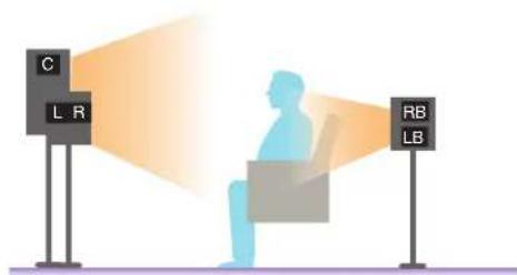
Figure 17. Speaker 5.1 Setup

Figure 18. Speaker 5.1.2 Setup

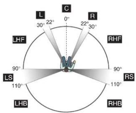
Figure 19. Speaker 5.1.4 Setup


radar
| Direction | Value | |---|---| | L | 30° | | C | 0° | | R | 22° | | RS | 90° | | LB | 135° | | LB | 150° | | LB | 135° | | RS | 110° | | RS | 110° | | RS | 135° | | RS | 150° | | RS | 135° | | RS | 110° | | RS | 90° | | RS | 90° | | RS | 30° |Figure 20. Speaker 7.1 Setup


radar
| Angle | Value | |---|---| | 0° | 22 | | 30° | 22 | | 60° | 30 | | 90° | 90 | | 120° | 110 | | 150° | 135 | | 180° | 150 | | 210° | 135 | | 240° | 150 | | 270° | 135 | | 300° | 150 | | 330° | 135 | | 360° | 150 | | 390° | 135 | | 420° | 150 | | 450° | 135 | | 480° | 150 | | 510° | 135 | | 540° | 150 | | 570° | 135 | | 600° | 150 | | 630° | 135 | | 660° | 150 | | 690° | 135 | | 720° | 150 | | 750° | 135 | | 780° | 150 | | 810° | 135 | | 840° | 150 | | 870° | 135 | | 900° | 150 | | 930° | 135 | | 960° | 150 | | 990° | 135 | | L | 22 | LH | 30 | LS | 90 | LB | 135 | RH | 90 | RS | 110 | RB | 135 | C | 22 | L | 30 | R | 22 | C | 30 | L | 22 | C | 30 | L | 22 | C | 30 | L | 22 | C | 30 | L | 22 | C | 30 | L | 22 | C | 30 | L | 22 | C | 30 | L | 22 | C | 30 | L = L C = C L = L C = C L = L C = C L = L C = C L = L C = C L = L C = C L = L C = C L = L C = C L = L C = C L = L C = C L = L C = C L = L C = C L = L C = C L = L B = L C = C L = L C = C L = L C = C L = L C = C L = L C = C L = L C = C L = L C = C L = L C = C L = L C = C L = L C = C L = L C = C L = L C = C L = L D = L C = C L = L C = C L = L C = C L = L C = C L = L D = L C = C L = L C = C L = L D = L C = C L = L D = L C = C L = L D = L C = C L = L D = L C = C L = L D = L C = C
Figure 21. Speaker 7.1.2 Setup

Figure 22. Subwoofer Placement
NOTES:
- To produce a good bass response, the subwoofer should be located at the front of the room, somewhere between either corner and a point about one third of the way along the front wall.
- The output channel used for the Left Back speaker in 7.1 configurations is also used for the Center Back speaker in 6.1 configurations.
Back Speakers
Back speakers can only be enabled if the Surround L/R speakers are enabled. Speaker enablement can be configured within the Speaker Configuration tab of PCS (see figure 37 on page 41.
The drop-down list of the Speaker Configuration tab determines whether the audio output channels for the back speakers are passed to the left back and right back (in 7.1 setups) or to a center back (in 6.1 setups).
To enable a configuration utilizing a center back speaker, the Center and Surround L/R channels must be enabled, and the Height/Downmix channel must be disabled.
If the two speaker option is selected, then source formats with discrete or matrix mixed 6.1 encoded channels outputs the back channel signal to both the left and right back channels equally.
By default, the back speaker option is set to 2 Speakers.
Bass Management
Low frequency sound is usually better handled by the subwoofer. Bass management creates the subwoofer channel by separating the low frequency information from the satellite speakers at a user-defined crossover point. This is summed with the Low Frequency Effects (LFE) information encoded in the source format. When no subwoofer is present, subwoofer content is sent to speakers set to Full Range (excluding the center speaker).
Speaker Settings
This feature sets bass management on or off for a particular speaker, defining the frequency range output by that speaker (see figure 37 on page 41). These settings also enable or disable the subwoofer and set the crossover frequency.
- Left and right front speakers and left and right surround speakers are set in pairs.
- The center speaker is set as an individual speaker.
- Back speakers can be set as a single speaker or as a pair of speakers, depending on the system configuration.
Bass Management
Small speakers are those which are set to Bass Management. The output to each speaker (other than the subwoofer) is limited to frequencies above the crossover frequency. By default, center, surround, and back speakers are set to Bass Management.
Full Range
Large speakers are those which are set to Full Range. The full range of audio frequencies from the audio source is fed through the output of each individual channel. By default, front speakers are set to Large.
Subwoofer
This option allows the subwoofer to be enabled or disabled. When the subwoofer is enabled, the signal contains filtered low frequency signals from speakers set to Bass Mangement in addition to the LFE signal from the input source. If the subwoofer is disabled, the LFE signal is mixed with the bass information of all speakers in the system that are set to Large, except the center speaker.
Crossover Frequency
The crossover frequency sets the boundary where the low frequency signals from designated output channels are incorporated into bass management. Low frequency signals are only taken from speakers that have been set to Bass Management (see Speaker Settings on the previous page). The bass management signal is passed to the subwoofer (if present) or speakers that have been set to Large (except for the center speaker) if a subwoofer is not present.
The crossover frequency can be adjusted within the range of 40 Hz to 250 Hz, with a default setting of 100 Hz. Speakers set to Bass Management (see Speaker Settings) output only signals above the set frequency.
Speaker Delay Settings
There are two different signal delays that compensate for different needs (see figure 38 on page 42).
Speaker distance delay — In a room where speakers are not equidistant from the listener, sound from the closest speaker reaches the listener before sound from the farthest speaker. This feature allows the user to enter the speaker distance value for each speaker output channel. The application calculates the delay values for the closest speakers, up to 700 ms, so that all audio arrives at a central location (the “sweet spot”) at the same time.
Lip sync offset — Video delays occur due to changes in programming from a source (TV, cable, satellite, or Blu-ray player) and also if the video signal has to be processed through another device between the source and the display. The lip sync offset feature allows the user to delay the audio sent to all output channels so that video and audio output are synchronized.
Since each source may need a different level of compensation, the lip sync offset for each input is independently adjustable from 0.0 to 300.0 ms. Apply lip sync offset to the audio until what is heard matches what is seen on the display.
Configure these settings using PCS (see Layouts and Speakers on page 78).
Test Signals
Test signals are used during setup to calibrate the level for each channel and to ensure proper connection between the individual output channels of the SSP 200 and the line level input channels of an audio signal processor, a receiver with built in amplifier, or a stand alone amplifier that powers the loudspeakers.
The three options for test signal source are Pink Noise, Dolby Noise, and Active Input. By default, the test signal is switched Off (see figure 39 on page 44).
Pink Noise — Pink noise is a signal generated by the SSP 200 that provides equal energy per octave to provide a flat response over all frequencies. The main purpose of pink noise is to calibrate the interaction of a speaker with its environment.
Dolby Noise — Dolby noise provides a bandpass-filtered noise, centered at 750 Hz with a 12 dB/octave roll off. This signal is also generated by the SSP 200 and is used to set speakers to the same level when calibrating the room.
Active Input — This option requires an external signal source, such as a signal generator, played through the selected input source. Generally, this is a device with an analog signal output, with the SSP 200 analog input used as the active input.
Signal generators are usually used to test specific decoding mode outputs. When the Active Input option is chosen, the speakers that receive the test signal can be specified.
Output Channel Trim Settings
This control adjusts the output channel trim level for each output channel to match the levels to the unique needs of any listening environment. The level can be adjusted within the range from -24 dB to 0 dB. The default setting for each speaker is 0 dB (see Test and Output Trim on page 44 for more information).
Listening Mode Settings
The SSP 200 provides multiple output mode options for each supported input audio format. By default, the device selects the most appropriate output mode based upon the channel content of the input format and available output channels. This is referred to as Auto Mode. The user may override this mode through Product Configuration Software (PCS). For additional mode information, see Listening Mode Options and Usage on page 27.
Equalization
Each analog output channel features a nine band parametric equalizer (or EQ) that allows the control of amplitude of each band, center frequency (which can be shifted, widened, or narrowed) and bandwidth (which is labeled "Q" for quality). Parametric equalization is used to improve the audio output in a specific acoustic environment:
Resonance reduction — Reduces the level at specific frequencies that are too loud.
Speaker compensation — Compensates for peaks and dips in individual speaker output response.
Tonal enhancement — Increases the level of frequencies within a broad or narrow range that sound too quiet.
Reference
This section provides information about the following topics:
- Source Formats
• Listening Mode Options and Usage
Source Formats
Source Formats refer to how audio material is embedded on the digital program. Blu-ray and streaming content from such providers as Netflix, Hulu, and others, provide multi-channel audio tracks. While digital audio components and analog are converted to 2-channel PCM audio. The following formats from the two leading theater-surround formats come from Dolby Laboratories and DTS. Here is a list of different formats and what you can expect from them.
| Audio Format Max | Maximum Number of Discrete Channels | Maximum Speaker Configuration | Connection with SSP 200 |
| Dolby Digital 6 5.1 HDMI, Coax, Optical | |||
| Dolby Digital Plus 8 7.1 HDMI, Coax, Optical | |||
| Dolby Digital Plus (Atmos) | 8 7.1.4 HDMI, Coax, Optical | ||
| Dolby TrueHD 8 7.1 HDMI only | |||
| Dolby TrueHD (Atmos) | 8 7.1.4 HDMI only | ||
| DTS (96/24) 6 5.1 HDMI, Coax, Optical | |||
| DTS-ES 7 6.1 HDMI, Coax, Optical | |||
| DTS-HD High Resolution Audio | 8 7.1 HDMI, Coax, Optical | ||
| DTS-HD Master Audio | 8 7.1 HDMI only | ||
| DTS Express 6 5.1 HDMI, Coax, Optical | |||
| DTS:X | 8 7.1.4 HDMI only | ||
| NOTE: The SSP 200 down mixes any format to match the configuration if the speaker configuration has fewer channels than discrete audio channels. | |||
Dolby Digital Source Formats
These include inputs 1 to 4 only.
Dolby Digital (2/0, 2/0 Surround, 5.1, Surround EX)
Dolby Digital is a flexible, discrete, digital technology for carrying multi-channel audio. Dolby Digital supports up to six discrete audio channels; five full range front and surround channels and a band-limited LFE (Low frequency effects) subwoofer channel. Most legacy Dolby Digital formats are supported by the SSP 200 including ProLogic (I & II), EX, and 2.0. Dolby Digital formats are 16-bit with up to 48 kHz sampling.
When the SSP 200 detects this source format the Dolby LED is lit. For stereo only formats, the 2-CH LED is lit.
Dolby Digital Plus/Dolby Digital Plus Atmos
Dolby Digital Plus and Dolby Digital Plus Atmos are extensions of Dolby Digital with a higher bit rate and channel count. Dolby Digital Plus supports up to eight discrete audio channels plus encoded channels including Dolby Atmos immersive Height (ceiling) channels. The SSP 200 supports up to 12 total output channels. This is the preferred format for most streaming services.
When this source format is present, the Dolby DLED is lit. If Dolby Atmos content is detected within the Dolby Digital Plus bitstream, the ATMOS LED is also lit.
Dolby TrueHD/Dolby TrueHD Atmos
Dolby TrueHD is a variable bitrate lossless codec, capable of supporting up to eight full-range channels (7.1) of 24-bit audio at 96 kHz. Just like Dolby Digital Plus, TrueHD Atmos content is encoded in the discrete channels. TrueHD formats offer the highest quality audio experience.
When this source format is present, the Dolby LED is lit. If Atmos content is detected within the TrueHD bitstream, the ATMOS LED is also lit.
DTS Source Formats (DTS)
These include inputs 1 to 4 only, unless otherwise noted.
DTS/DTS 96/24
Like Dolby Digital, DTS is a flexible, discrete, digital technology for carrying multi-channel audio. DTS supports up to six discrete audio channels; five full range front and surround channels and a band limited LFE (Low frequency effects) subwoofer channel. All DTS formats have 24-bit depth, which allows more audio information to be stored compared with the normal 16-bit depth. DTS 96/24 formats improve audio further by using the 96 kHz sampling frequency instead of the standard 48 kHz.
When this source format is present, the DTS LED is lit.
DTS ES (96/24, Matrix, Discrete)
Similar to standard 5.1 DTS formats, DTS ES (DTS Extended Surround) includes an additional Back channel. This sixth channel allows the user to configure mono back speakers or split it for a 7.1 configuration.
When this source format is present, the DTS LED is lit.
DTS-HD High Resolution Audio
DTS-HD High Resolution Audio delivers up to 7.1 channels of audio at 96 kHz sampling frequency and 24-bit resolution. DTS-HD High Resolution is implemented as a "base" DTS stream plus an extension containing two additional channels; in this way, it is compatible with legacy DTS-only encoding.
When this source format is present, the DTS LED is lit.
DTS Express
DTS Express delivers up to 5.1 channels of audio at 48 kHz sampling frequency and 24-bit resolution.
When this source format is present, the DTS LED is lit.
DTS-HD Master Audio & DTS:X
DTS-HD Master Audio adds support for lossless audio streams up to a maximum sample rate of 192 kHz at 24-bit resolution. It is also the carrier for DTS:X object-based surround sound with encoded channels providing content to Height (ceiling) speakers.
When this source format is present, the DTS LED is lit.
If DTS:X content is detected within the bitstream, the DTS:X LED is also lit.
PCM Digital Source Format (PCM)
These include inputs 1 to 4 only.
PCM source formats represent 2-channel as well as multichannel (up to 7.1) uncompressed, digital input signals. Multichannel PCM can be processed using only the HDMI input.
When the SSP 200 detects a 2-channel PCM source format, both the PCM and 2-CH LEDs light. When a multichannel PCM format is present, only the PCM LED lights.
2-Channel Source Format (2CH)
Analog
This includes input 5 only.
Any balanced or unbalanced stereo signal (or two balanced or unbalanced mono sources) is accepted. When this input is selected, the front panel 2-CH LED is active.
Digital
These include inputs 1 to 4 only.
When the SSP 200 detects any two channel digital signal (including PCM 2-channel, Dolby Digital 2/0, Dolby Digital 2/0 Surround, or DTS 2-channel) the 2-CH LED lights.
Sampling Frequency
The following table shows the most common sampling frequencies of digital inputs and the uses with which they are most often associated.
| Sampling Frequency (kHz) | Use |
| 32 Used | for some cassette recordings, speech, and all other audio where smaller files are desired, with only slight compromise on sound quality. In the past, used with products such as NICAMs. |
| 44.1 Audio | CD, also commonly used with MPEG-1 audio (VCD, SVCD, MP3). Adopted from the PCM adaptor using PAL video tapes (294 lines by 3 samples by 50 frames per second). |
| 48 Digital | sound used for mini DV, digital TV, DVD, DAT, films, and professional audio. |
| 88.2 Sampling rates used by professional recording equipment when the destination is CD (multiple of 44.1 kHz). | |
| 96 DVD-Audio, some LPCM DVD tracks, DTS 96/24, and DTS 96/24 ES Matrix 6.1 source formats always output this sampling frequency. | |
| 192 | Blu-ray and HD-DVD, Dolby TrueHD and DTS-HD Master Audio output this sampling frequency when there are six discrete channels. |
Listening Mode Options and Usage
Listening Mode Options
The SSP 200 listening modes allow users to upmix or downmix audio content to match their speaker configuration. By default, all listening modes are set to Auto. The auto setting maximizes source formats to the required speaker configuration based on what is available in the room. For example, Dolby Atmos or DTS:X downmixes to 5.1 if there are only 5 full range speakers and a sub-woofer in the speaker configuration.
Source formats that natively use fewer speakers such as an analog source or the original 5.1 release of older DVDs can be upmixed so all of the speaker channels are utilized.
Auto
The SSP 200 selects an appropriate output mode based on input format and available output channels. The encoded channels pass through to the outputs if the required output channels have been enabled in the speaker configuration. Otherwise, the encoded channels are downmixed accordingly.
Stereo
This mode plays a stereo source in its pure, unprocessed form. Multichannel formats are downmixed to a stereo output signal.
Mono
This mode plays mono source material or stereo source material that has been mixed to a mono form. It can be used to downmix a multichannel source format into a single mono output signal.
Additionally, the user can select whether the mono signals are output to the center channel (Center Only) or a dual mono signal is sent to the right and left front channels (Front L+R Only). The default option is Front L+R Only.
Stereo to All
This mode plays stereo or downmixed stereo sources through all output pairs in the system.
Mono to All
This mode plays mono or downmixed mono sources to all outputs in the system.
Dolby Surround
The Dolby Surround upmixing engine is utilized to upmix input audio to some or all available output channels.
DTS Neural:X
The DTS Neural:X upmixing engine is utilized to upmix input audio to some or all available output channels.
Product Configuration Software
The SSP 200 surround sound processor can be configured using Extron Product Configuration Software (PCS). This section describes:
- Downloading PCS from the Extron Website
• Using PCS Software - Updating Firmware Using PCS
Downloading PCS from the Extron Website
Visit www.extron.com to download and install the PCS software. An Extron Insider Account is required and then the PCS program can be downloaded free of charge.
NOTE: Also you can download the latest version of firmware for your product (see Updating Firmware Using PCS starting on page 58).
- Mouse over the Download tab at the top of the homepage (see figure 23, ①).
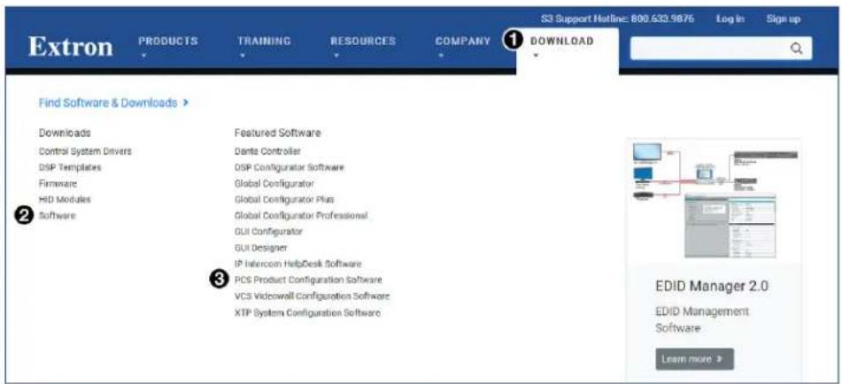
Figure 23. PCS Software Link on Download Tab
- Click the Software link (②) or, if the software is listed, click directly on the PCS Product Configuration Software link (③).
The PCS window opens with the current available version (see figure 24).

Figure 24. PCS Software Download Link
- Click Download (①) and follow the on-screen instructions.
Using PCS Software
Connecting to the SSP 200
- Ensure that PCS is installed on the control PC (see Downloading PCS from the Extron Website on page 29).
- Connect the PC to the SSP 200 processor. PCS communicates with the SSP 200 via the front panel configuration port with a standard USB mini-B port (see Connecting to the USB Port on page 16), the rear LAN connector, or the rear panel RS-232 connector.
- Open PCS on the PC from the PCS icon loaded on the desktop (optional, see image on the right) or from the Start menu, click Start > Programs > Extron Electronics > Extron Product Configuration Software.
The Product Configuration Software opens to the Device Discovery screen (see figure 25). Devices that are either networked or connected to the PC via USB are listed.

Figure 25. PCS Device Discovery Screen
- Select the SSP 200 device by clicking on it to highlight it in the list (1).
- Click Connect (②).
The Product Configuration Software opens to the device main menu (see figure 26 on the next page).
Main Menu
NOTE: The SSP 200 tab (top left) has a green indicator, indicating that the device connection is live.

Figure 26. SSP 200 PCS Main Menu
The configuration pages have a global navigation bar from which each of the individual configuration pages can be accessed.
These tabs are:
① Input/Output Config
③ Audio Config
② EDID Minder
4 General Settings
The I/O Panel (5) is always available and can be collapsed by clicking the arrow button on the top right of the panel.
I/O Panel
The I/O Panel on the left side of the main window allows you to select an input and see its current status. The fader on the bottom portion is the Main Volume. This sets the volume level for all active speaker outputs of the SSP 200. Below the Main Volume fader is a Mute button that mutes all active speakers (see figure 27).
The master volume can be adjusted between 0% and 100%. The current volume setting is displayed in the text box. The volume can be changed in any of the following ways:
- Grab and drag the slider bar to adjust volume in 1% steps.
- Click the slider bar to make it active and use the up and down arrows beside the text box to adjust the volume in 1% steps.
- Click in the text box and type a desired volume percentage in 1% steps. Do not type the “%” character.
- Click the slider bar to make it active and use the
and keys on the keyboard to adjust the volume in 1% steps. - Click the slider bar to make it active and use the
and keys on the keyboard to adjust the volume in 5% steps.
The Mute button toggles between muting or unmuting all channel outputs.
NOTES:
- Switching inputs disables the mute function and restores the volume setting.
- The round indicator at Input Select buttons 1 through 4 turn green when the input selected has an active input. Input 1 (HDMI)
- Input Select buttons 2 through 4 show EXP if the user configures an input to be replaced.
- The round indicator at the Input 5 button turns red when the analog input signal is clipping. ● Input 5 (Analog)


Figure 27. I/O Panel
Input/Output Config
The Input/Output Configuration panel allows the user to configure the active input and output signals (see figure 28 on the next page).
Input Configuration
The Input Configuration panel allows you to view the Resolution and HDCP Status of the HDMI input and set the input to HDCP Authorized.
In addition, the panel allows you to enable and set the DMP EXP Input and adjust the gain for Analog Input 5.

Figure 28. Input/Output Configuration Panel
HDMI Input 1
① Resolution — Displays the resolution of the HDMI input.
② HDCP Status — Indicates the HDCP status of the input source. The HDMI input negotiates and authenticates HDCP with the source device if the source requires HDCP encryption.
| Symbol Definition | |
| [X2K0] | The signal is HDCP encrypted. |
| [X360] | The signal is not encrypted. |
③ HDCP Authorized — Select this checkbox to turn HDCP Authorized on (default) or off. When disabled (Off), the source is blocked from encrypting its output. This may result in some content not being passed to the output.
DMP EXP Input
4 Replace Input channel — Enables the EXP Input by replacing one of the selectable input channels Input 2 (Coaxial), Input 3 (Optical), or Input 4 (Optical).
⑤ Set EXP Input channel pair — Sets the EXP Input channel pair to two of the 16 possible audio channels.
Analog Input 5
⑥ Analog Input Gain — Adjusts the gain of the signal on Input 5. When Input 5 (Analog) is selected, the Analog Input Gain controls are available to adjust the gain either by adjusting the fader manually or by entering a gain value in dB.
Output Configuration
HDMI Loop Out
⑦ Audio — Establishes which audio stream is routed to the HDMI Loop Out. The three options are No Audio, Follow Input audio, or the Downmix audio.
⑧ HDCP Status — Indicates the HDCP status of the output device. The HDMI input negotiates and authenticates HDCP with the sink device, if the sink requires HDCP encryption.
⑨ HDCP Mode — Allows the user to either Always Encrypt Output or to Follow Input. When Always Encrypt Output is selected, the digital input reports as an HDCP authorized sink to a source. For source devices that require encryption, enable the HDCP Authorized checkbox (see figure 28, ③, on the previous page).
Listening Mode Setup
This panel allows you to adjust the listening mode depending on the input and source format (see figure 29).

Figure 29. Listening Mode Setup
① Listening Mode Setup — This drop-down list allows you to select which input you want to set the listening modes.
② Input Source Format/Listening Mode — These drop-down lists allow you to select which listening mode you want to assign for each input source format within the selected input.
EDID Minder
EDID Minder manages the EDID information of the HDMI input. Click the EDID Minder tab on the global navigation bar to open the EDID Minder page.
This section includes the following:
• EDID Minder Panels
• EDID Filters
- Adding EDID to the Favorites Panel
- Importing EDID to the EDID Library
• EDID Assignment
• Searching for EDID by Name
• EDID Report
The EDID properties currently assigned to the HDMI input are displayed in the list of inputs. The audio input format listed in an EDID is determined by the audio input format selected on the Audio Configuration page (unless a custom EDID is used).
NOTE: If an analog custom EDID file is assigned to a digital input or a digital custom EDID file is assigned to an analog input, the display may not appear correctly.
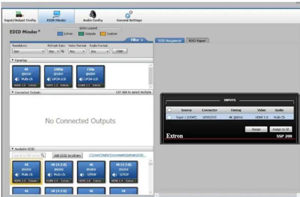
Figure 30. EDID Minder
EDID Minder Panels
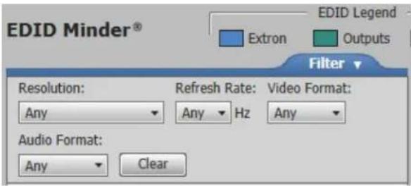
- Filter — Displays various filters that can be enabled to easily locate specific EDID (see figure 31).
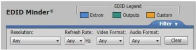
Figure 31. Filter Panel
- Favorites — Displays commonly used EDID which can be added to the panel for quick access (see figure 32).

Figure 32. EDID Favorites Panel
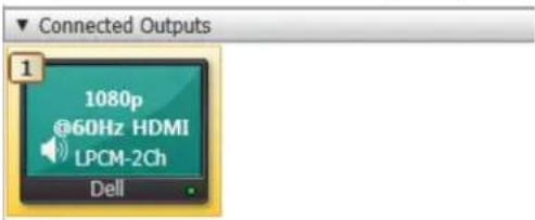
- Connected Outputs — Displays the EDID (color-coded green) of the output connected to the SSP 200 HDMI Thru port (see figure 33).

Figure 33. Connected Outputs Panel
• Available EDID — Displays the available EDID located on the connected unit or the local PC (see figure 34).
• Blue - Extron factory-default EDID
• Yellow - Custom user-saved EDID

Figure 34. Available EDID Panel
• INPUTS — Displays the current EDID of the connected input (see figure 35).

Figure 35. Inputs Panel
EDID Filters
The filters can be used to easily locate specific EDID.
Applying a Filter
-
Navigate to the Filters panel on the EDID Minder screen.
-
Select an EDID setting from the drop-down list of the associated filter.
The available EDID that match the filter selection are displayed in the library.
- Repeat step 2 to apply more filters.
Clearing Applied Filters
To reset all the filters, click the Clear button.
Adding EDID to the Favorites Panel
Commonly used EDID can be added to the Favorites panel for quick access.
-
Navigate to the Favorites panel on the EDID Minder screen.
-
Click and drag the desired EDID to the Favorites panel.
The EDID is copied to the Favorites panel.
EDID can also be added to the Favorites panel by right-clicking the desired EDID and selecting Copy, then pasting the selected EDID into the Favorites panel.
Importing EDID to the EDID Library
Non-factory-default Extron EDID files can be imported into the local EDID library that is locally stored on the connected PC.
Accessing the EDID library
-
On the EDID Minder screen, navigate to the top right of the Available EDID panel.
-
Click the blue link (highlighted in red box).
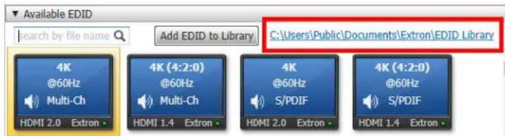
The EDID library on the local PC opens.
Accessing a non-factory default EDID into the EDID library
- On the EDID Minder screen, navigate to the Add EDID to Library button to the right of the Available EDID search box.
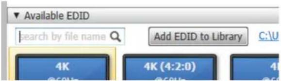
- Click Add EDID to Library. The Browse Add EDID to the Library pop-up window opens.
- Locate the previously saved EDID file (EDID files have .BIN extensions) to be added to the EDID library and click Open.
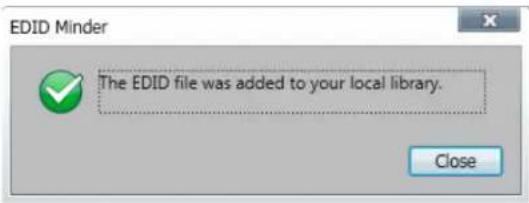
- The following pop-up window displays, indicating that the EDID file was added to your EDID library. Click Close to continue using the software.
EDID Assignment
The following can be assigned to the inputs of the connected SSP 200:
• Extron factory-default EDID
• EDID from the display connected to the SSP 200 output port
• Non-factory default EDID that have been imported or saved to the PCS EDID library
Assigning a Factory-Default Extron EDID
- Navigate to the Available EDID panel on the EDID Minder screen.

- Select the desired EDID (represented by a blue display icon).
- Select the check box for Input 1 on the INPUTS panel.

- Click Assign. The EDID is assigned to the input and is displayed in the INPUTS panel. Alternately, click Assign to All on the INPUTS panel if you would like to assign the same EDID to all inputs.
EDID can also be assigned by dragging and dropping the desired EDID directly onto the Inputs panel.
Assigning a Non-Factory-Default EDID
- Navigate to the Available EDID panel on the EDID Minder screen.

-
Select the desired EDID (represented by a orange display icon).
-
Select the check box for Input 1 on the INPUTS panel.

- Click Assign. The EDID is assigned to the input and is displayed in the INPUTS panel. Alternately, click Assign to All on the INPUTS panel if you would like to assign the same EDID to all inputs.
EDID can also be assigned by dragging and dropping the desired EDID directly onto the INPUTS panel.
Assigning EDID from a connected output
- Navigate to the Connected Outputs panel on the EDID Minder screen.
-
Click the EDID displayed (represented by a green display icon).
-
Select the check box for Input 1 on the INPUTS panel.

- Click Assign. The EDID is assigned to the input and is displayed in the INPUTS panel. Alternately, click Assign to All on the INPUTS panel if you would like to assign the same EDID to all inputs.
EDID can also be assigned by dragging and dropping the desired EDID directly onto the INPUTS panel.
Searching for EDID by Name
- On the EDID Minder screen, navigate to the search box located at the top of the Available EDID panel (highlighted in red box).

- Start typing the name of the desired EDID. Only EDID that contain the entered text are left in the Available EDID panel.
EDID Report
Click the EDID Report tab to view the translated data contained within the selected EDID file (see figure 36).

Figure 36. EDID Report Tab
Audio Config
The Audio Configuration page has four tabs.
NOTE: The Audio Configuration tabs should be adjusted in the order they appear.

- Speaker Configuration
- Speaker Delay
• Test and Output Trim
• Speaker Equalization/Output EQ
Speaker Configuration
Click the Audio Config button (see figure 26, ③, on page 31). The Audio Configuration window opens to the Speaker Configuration panel (see figure 37).

Figure 37. Speaker Configuration
The various controls can be adjusted to configure the speakers as needed.
① Speaker Enablement — This feature determines which output speaker channels are enabled and pass audio. There are additional drop-down lists for Back and Height speakers in those positions or if a stereo downmix on the analog output is required.
② Bass Management/Full Range — This selection is only enabled when its corresponding speaker channel is enabled. When Bass Management is selected, only frequencies above the crossover frequency threshold is sent to the corresponding speaker channels. When Full Range is selected, all frequencies are sent to the corresponding speaker channels.
③ Crossover Frequency — When Bass Management is selected for a particular channel, the frequencies below this threshold are sent to the subwoofer channel (or Full Range speaker channels when the subwoofer channel is disabled) and the frequencies above this threshold are sent to the speaker channel.
4 Configuration Display — This graphics box shows which speaker channels are active (see figure 37 on the previous page). Only the speakers enabled are displayed. If Full Range is selected for a particular channel then the speaker is represented by a large icon. If Bass Management is selected for a particular channel then the speaker is represented by a small icon.
Speaker Delay
These controls introduce a signal delay for each enabled speaker (see figure 38). The two main reasons to adjust the signal delay are:
- To compensate for unequal distances between the speakers and the listener, which causes sound from different speakers to reach the listener at different times.
- To compensate for a lack of coordination between the audio and the accompanying video signal.
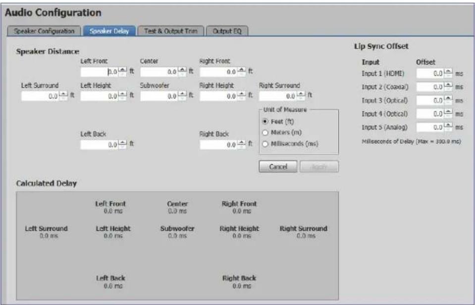
Figure 38. Speaker Delay
Speaker Distance
When speakers are arranged in a room, there is a central location or “sweet spot” that offers the best listening point. However, even in that central location, the speakers are not necessarily all equidistant from the listener, and the sound from the closest speaker reaches the listener before the sound from speakers that are further away.
Speaker distance settings delay the signals going to each individual speaker (from 0 to 700 ms) so that the signals from all the speakers are synchronized and reach the listener simultaneously. The default setting for each speaker is 0 ms.
Speakers that are not available in the current configuration are not displayed. When the back surround is set to one speaker, the right back speaker is unavailable and the left back speaker is renamed as the center back.
Use PCS to set speaker delays, using either of the following methods.
Two Person Setup
NOTE: Setting up speaker delays is easier with two people. If only one person is available, the position of the ears of the listener must be marked precisely. A pile of boxes could be used to ensure that the distances are consistently measured to the correct height. Do not try to guess ear positions, as this introduces measurement errors.
- Pick an ideal central location where all speaker output signals converge.
- Use a tape measure to measure the distance from each speaker to the convergence location. Be sure to measure to the same spot from each speaker.
NOTE: Measurements from the speaker must be to the midrange driver in a three-way speaker or from halfway between the tweeter and the woofer in a two-way speaker. Measurements to the convergence location must be at ear height.
- In the Unit of Measure box, click the Feet (ft) or Meters (m) radio button to select the units and enter the Speaker Distance values for each speaker in the boxes. The up and down arrows increase the distance in increments corresponding to steps of 0.1 ms (0.12 feet or 0.03 meters). The software automatically determines the farthest speaker and calculates the delay time (in milliseconds) for each speaker.
These values are shown in the Calculated Delay box. The current values are shown in blue, changes (yet to be saved) are shown in orange.
- After all of the speakers have their measurement entered, the Apply button appears. Click the button to save the changes. The new values (previously in orange) are shown in blue as the current values and there are no values displayed in orange.
To retain the original values, click Cancel instead of Apply.
Setup with a Real Time Analyzer (RTA) calibration tool
- Choose an ideal central location on which all speaker output signals converge.
- Place the microphone from the RTA at ear level in the convergence location.
- Select Active Input on the Test & Output Trim tab (see figure 39 on the next page).
- Play the audio source. This can be an analog source, provided by the RTA.
- Use the Test Signal Output buttons in the Test & Output Trim tab to select which speakers are tested and the order in which the speakers are tested.
-
Use the RTA to measure the speaker distance (in ms) for each channel.
-
In the Unit of Measure box on the Speaker Delay tab, select the Milliseconds (ms) radio button and enter the values for each speaker (in ms) into the boxes. The up and down arrows increase the distance in increments of 0.1 ms.
These values are shown in the Calculated Delay box. The current values are shown in blue, changes (yet to be saved) are shown in orange.
- Repeat steps 5 through 7 until the speaker distance has been entered for all available speakers.
NOTE: The maximum allowable distance for the furthest speaker is 700 ms
- Click Apply. New values are shown as the current values, in blue. No values are displayed in orange.
To retain the original values, click Cancel instead of Apply.
Lip Sync Offset
Lip sync offset compensates for a lack of coordination between the audio and the accompanying video signal. This frequently occurs if the video signal has undergone complex manipulation that can delay it several milliseconds relative to the audio signal.
Since some sources may require more manipulation than others, the Lip Sync Offset is set for each source individually to synchronize the audio for that source with the corresponding video signal.
Enter the appropriate value for each input in the corresponding Lip Sync Offset box. This delay is added to every available speaker to resynchronize the video and audio signals.
Test and Output Trim
Click the Test & Output Trim tab to access the various output controls (see figure 39).

Figure 39. Test and Output Trim
Several factors can affect the sound level reaching the listener from different speakers. These factors include the distance from the speaker to the listener, slight variations between the output channels of a single amplifier, and variations between the individual speakers. Use the output trim to set the output level of each individual channel to compensate for all these variations and ensure that the sound level reaching the listener is the same from all speakers.
This page also provides a test signal utility.
Test Signal Output
Test signals are used during setup to calibrate the level of each channel and to ensure proper connection between the individual output channels of the SSP 200 and the line level input channels of an audio signal processor, a receiver with a built in amplifier, or a stand alone amplifier that powers the loudspeakers.
Selecting test signal source
There are three test signal options: Dolby Noise, Pink Noise, or Active Input. They are selected from the mutually exclusive Signal Type buttons. The Dolby Noise and Pink Noise test signals are generated by the SSP 200.
NOTE: If the active input is selected as the test signal, then its listening mode is set to Mono to All when the test sequence is active. Its listening mode is automatically restored once the test sequence is set to Off.
Selecting speakers to be tested
The speakers enabled in the speaker configuration are displayed in the Send Test Signal panel. Speakers that are not enabled are not displayed. Clicking on a speaker within the graphics box selects or deselects it from the list of speakers to be tested. For an example, the Right Back (RB) speaker in the illustration below has been deselected.

Speaker test sequence
To run an automatic test sequence:
-
Select the Automatic button.
-
Select the On button to start the test sequence. This sends the selected test signal to each speaker channel individually. Each speaker channel receives the test signal for two seconds before the test signal is routed to the next channel in the sequence. In the example below, the Left Surround (LS) speaker is shown currently receiving the test signal.

- Select the Off button to switch off the test signal and end the test sequence.
To test the speakers manually:
- Select the Manual Selection button.
- Select the On button to start the test sequence.
- Select a speaker in the graphics box to route the test signal to that speaker channel.
- Select the Off button to switch off the test signal and end the test sequence.
NOTE: Enabling the global Mute in the I/O Panel disables an active test sequence.
Output Trim
The Output Trim sliders control the audio signal level for each individual channel output. Only channels that are enabled in the current speaker configuration are available. Output trim is adjustable from -24 dB to +0 dB. The current value for each output channel is shown in the text box.
Extron recommends using a Sound Pressure Level (SPL) meter to set the output trim for each speaker:
-
Set up the SPL meter at the sweet spot in the room.
-
Send a test signal, generated as described in Test Signals on page 22, to each individual speaker in turn. Extron recommends using the Dolby Noise signal and sending the signals to the speakers manually.
NOTE: The test signal should have a sound level at least 20 to 30 dB above ambient levels.
-
Measure and write down the sound pressure for each speaker.
-
To avoid decreasing the maximum output volume (see the note above), Extron recommends that you use the speaker with the lowest SPL reading as the zero reference point. Then attenuate all the other speakers by the required amount to balance all speakers.
In the following table, the SPL readings for five channels are given in second column. Channel 4 has the lowest reading and is used as the zero reference point. The difference between each speaker and the zero reference is calculated in column 3. This is the adjustment that must be made to the output trim for that channel.
| Channel SPL | Reading Output Trim | Adjustment (dB) |
| 1 75 -1 | ||
| 2 76 -2 | ||
| 3 79 -5 | ||
| 4 74 0 | (zero reference channel) | |
| 5 77 -3 |
-
Use any of these methods to adjust the output trim for each speaker.
-
Grab and drag the slider bar to adjust output trim in 1 dB increments.
- Click the up and down arrows besides the text box to adjust it in 1 dB increments.
- Click one of the output trim slider controls to activate it and use the
and keys on the keyboard to adjust it in 1 dB increments. - Click one of the output trim slider controls to activate it and use the
and keys on the keyboard to adjust it in 5 dB increments. - Highlight the value in the text box, type a number (omit the dB), and press
on the keyboard.
The Reset button returns the output trim values for all speakers to the default value (0 dB).
Speaker Equalization/Output EQ
The Output EQ tab brings up the Speaker Equalization that provides nine parametric EQs for each output channel (see figure 40).

line
| Frequency | Level | | --------- | ----- | | 20 | 0 | | 50 | 12 | | 100 | 0 | | 1K | 0 | | 10K | 0 |Figure 40. Speaker Equalization/Output EQ
The default frequency values correspond to a nine-band graphic equalizer, which provides a starting point for refining the output signal from each speaker channel.
All the properties of the SSP 200 parametric filters can be adjusted by the user.
The numbers are used to select the filters for utilizing the copy/paste function or to change the focus on the graph to the left. Filters are automatically selected when a parameter is adjusted.
The Active column has toggle buttons for activating (or unbypassing) a filter. A filter only affects the signal if it is active (blue).
Speaker Selection
To begin the adjustment, first select the speaker to be configured from the Speaker Equalization For drop-down list.
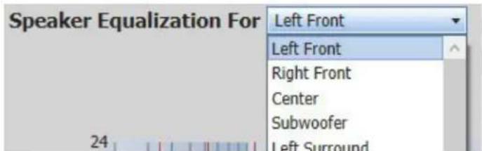
Figure 41. Speaker Selection
Filter Parameters
These four fields (on the right side of the page) control the parameters that can also be adjusted in the graph.
- Filter number — Selects a filter to display on the graph or copy and paste functionality.
- Frequency — Adjusts the center frequency of the filter.
- Boost/Cut — Adjusts the amount of amplification or attenuation applied to that specific filter.
- Q — Adjusts the bandwidth to where the boost or cut is applied. As the Q value increases, the bandwidth becomes narrower.
NOTE: When values are altered in the filter parameter fields, the graphic display is updated to reflect the changes.
Modifying Filter Parameters
The graph in the Filter dialog box displays a graphical representation of the selected and composite filters.
- An orange line indicates the composite curve of all active filters.
- A blue line indicates the selected filter.
- Inactive filters do not contribute to the orange composite curve. However, when selected, an inactive filter appears as a dotted line independent of the composite curve.
To modify Frequency
- In the Filter dialog box, select the filter to be modified. To do so, either click the filter number at the left of the Filter menu (figure 42) or click the appropriate Frequency handle below the graph (figure 43).

Figure 42. Filter Menu

Figure 43. Frequency Handles
- Click and drag the Frequency handle left or right to desired position or value. Alternatively, enter the value in the Frequency field for the selected filter, or click the up or down arrows next to the field until the desired value is displayed.
To modify Boost/Cut (Parametric):
- In the Filter dialog box, select the filter to be modified. To do so, either click the filter number to the left of Filter menu or click the appropriate Frequency handle below the graph.
- Click and drag the Boost/Cut handle, located at the center frequency in the graph (see figure 44 on the next page), up or down to the desired position or value. Alternatively, enter the value in the Boost/Cut field for the selected filter, or click the up or down arrows next to the field until the desired value is displayed.

natural_image
Pure geometric diagram with dashed lines and diamond markers on grid background (no text or symbols)Figure 44. Center and Outer Handles
To modify Q (Parametric filters):
- In the Filter dialog box, select the filter to be modified. To do so, either click the filter number to the left of Filter menu or click the appropriate Frequency handle below the graph.
- Click and drag one of the Q handles within the graph, located at the lower or upper frequency on the filter curve, left or right to the desired position or value.
Alternatively, enter the value in the Q field for the selected filter, or click the up or down arrows next to the field until the desired value is displayed.
EQ Filter Copy and Paste
Copy and Paste buttons are available to streamline your repeat filter settings. The buttons are located at the bottom right of the page.

Figure 45. EQ Filter Copy and Paste Buttons
To copy and paste a setting:
- Click a number to select filter settings to copy.
- Click the Copy () button.
- Click a different filter number to paste.
- Click the Paste () button.
General Settings
General Settings
Click the General Settings button (see figure 26, ③, on page 31).
The General Settings panel (see figure 46) allows you to adjust:
- Dolby Settings
- DTS Settings
• Dynamic Range Compression - Mono Settings
• Front Panel Lockout (Executive Mode)
The General Settings panel also allows you to access:
- Hardware Settings
• Communication Settings (after opening the Hardware Settings panel)
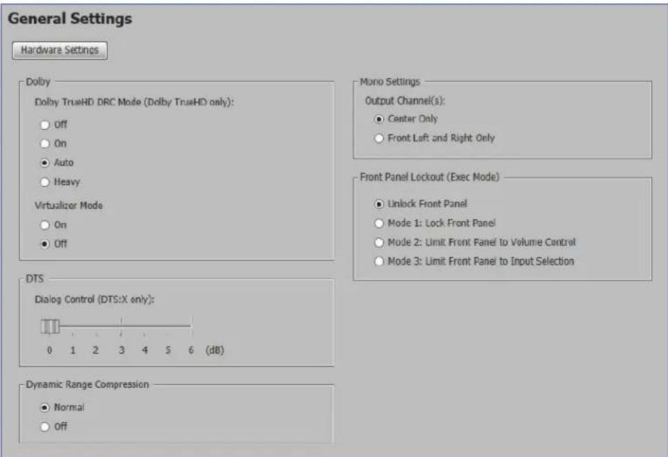
Figure 46. General Settings
Dolby Settings
Depending on the listening environment, listener preference, or both, reducing the dynamic range of an audio program may be desirable. To limit the dynamic range, Dolby TrueHD DRC Mode applies dynamic range compression to the Dolby TrueHD audio content. When dynamic range compression is applied, the high audio levels of content are cut (attenuated) and the low levels are boosted (amplified).
Using the Virtualizer Mode on a Dolby signal gives you the effect of a virtual height and surround effect from traditional speaker layouts without the use of height speakers in systems with more than 2 channels.

DTS Settings
The DTS Dialog Control setting determines the amount of gain increase (in dB) for the dialog audio tracks in a DTS:X stream. This is useful for movies where the dialog is perceived as too quiet when compared to the music or score.

Dynamic Range Compression
This setting determines the amount of compression applied. This setting does not apply to Dolby TrueHD streams.

Mono Settings
This setting determines how the SSP 200 outputs its mono channels when a mono listening mode is selected, either the center channel or both the front left and right only.

Front Panel Lockout (Executive Mode)
This setting determines what functionality is available on the front of the device.
- Unlock Front Panel — Allows all of the buttons to operate normally.
• Mode 1 — Removes the functionality of every button on the front of the device.
• Mode 2 — Limits front panel functionality to just volume control.
• Mode 3 — Limits front panel functionality to just input selection.
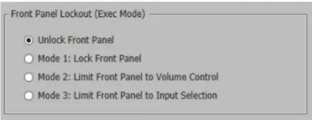
Hardware Settings
Click the Hardware Settings button (see figure 46 on page 50) to access the Unit Information, Device Name, Date and Time, and Password panels.
Unit Information
The Unit Information panel gives a non-configurable view of information about the connected device (see figure 47 on the next page).
The following device information is displayed:
- Part number
- Model name
- Model description
- Firmware version
• Temperature (inside device) - Device name
- DHCP status
- IP address
- Subnet mask
- Default gateway address
DNS server - MAC address
Click Edit Communication Settings (①) to go to the Communication Settings panel. Click Cancel (②) to return to the General Settings panel.

Figure 47. Hardware Settings: Unit Information
Device Name
The Device Name panel allows you to assign or change the name or hostname of the connected device (see figure 48).

Figure 48. Hardware Settings: Device Name
NOTE: The device name is used as the hostname of the SSP 200.
To assign or change the hostname:
-
Enter a name for the device in the name field (see figure 48, ①, on the previous page). This name can be up to 63 characters in length with no spaces between characters. Only alphanumeric characters and the hyphen are valid. The first character must be alphabetical, and the last one cannot be a hyphen (-). If an invalid name is entered, a red symbol appears to the right of the name field.
-
Click the Apply button (②) to change the name or click the Cancel button (③) to keep the previous name.
To reset the device name to the default: Click the Reset to Default button ④). The default device name consists of the model name, followed by the last three hexadecimal character pairs of the product MAC (hardware) address. All parts of the name are separated by hyphens (for example: SSP-200-FF-FF-FF).
Date and Time
-
Click the Date and Time button to access a menu to change the date, time, and time zone of the device (see figure 49). You can also click the Sync to PC button to synchronize the device with a connected computer to align the current date and time.
-
Click the Apply button when done. Or click Cancel to return to the previous menu with no changes.
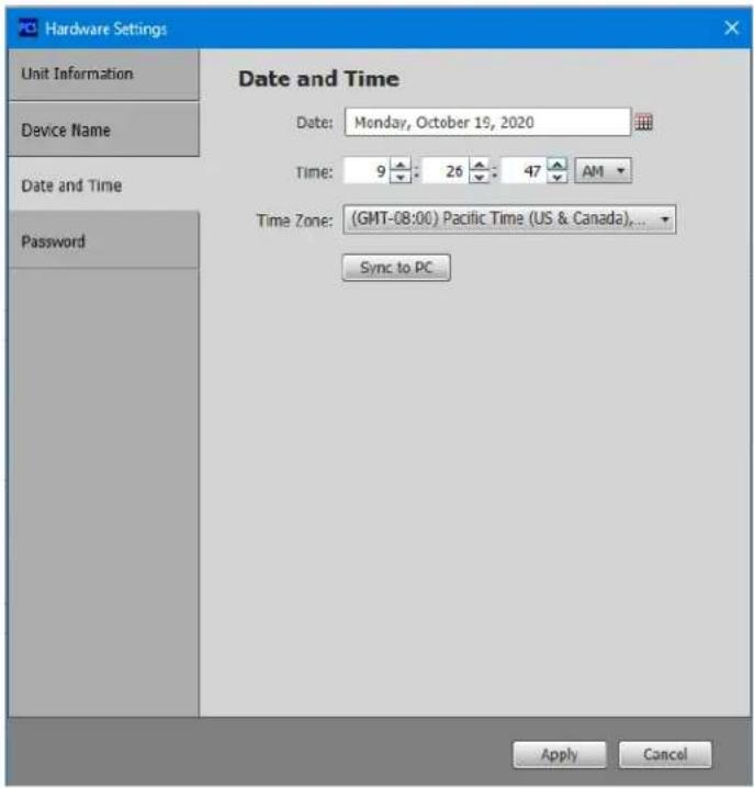
Figure 49. Hardware Settings: Date and Time
Password
The Password panel (see figure 50) allows the user to set an administrator and user password on the device. Administrators and users can view all settings on the device. Administrators have the ability to make adjustments to any setting. Users can make changes to a limited subset of settings.
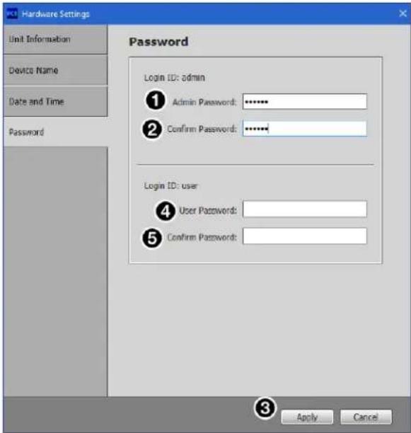
Figure 50. Hardware Settings: Password
NOTES:
- A username is required to access the internal web pages or the device through the PCS program. When prompted, enter admin as the username for administrator passwords or user as the username for user passwords.
- A password can be up to 128 characters in length. All man-readable characters are permitted except "|". Password cannot be a single space. Passwords are case-sensitive.
- The factory configured passwords for all accounts on this device have been set to the device serial number. Passwords are case sensitive. If the SSP 200 is reset, the passwords revert to the default, which is extron.
To create or change an administrator password:
- In the Administrator Password field (①), enter the desired administrator password.
- In the Confirm Password field (②), reenter the administrator password.
- Click the Apply button (③).
To create a user password:
NOTE: A user password cannot be set until an administrator password has been set.
- In the User Password field (④), enter the desired user password.
- In the Confirm Password field ( 5 ), reenter the user password.
- Click the Apply button (③).
Communication Settings
Click the Edit Communication Settings button (see figure 47, 6, on page 53) on the Hardware Settings panel to open the Communication Settings dialog box.
The Communication Settings dialog box (see figure 51) allows you to view and adjust device settings for RS-232 and Ethernet connections.

Figure 51. Communication Settings
If you do not want to implement any changes, click Cancel (⑨) to return to the General Settings panel or click the Go To Hardware Settings button (⑥) to return to the Hardware Settings panel.
The Use DHCP check box (①) directs the SSP 200 to ignore any entered IP addresses and obtain an IP address from a Dynamic Host Configuration Protocol (DHCP) server (if the network is DHCP capable). Contact the local system administrator to determine if this is the appropriate selection. Click the Apply button (⑧) to make changes take affect.
The device MAC address (6) is also displayed on this panel though it cannot be changed.
To configure the Ethernet settings for use with DHCP:
- Select the Use DHCP checkbox (①).
- Click the Apply button (⑧).
To configure the Ethernet settings with a static IP address:
- Ensure the Use DHCP checkbox (①) is not selected.
- In the IP Address field (②), enter an IP address.
- In the Subnet Mask field (③), enter the subnet mask if required.
- In the Default Gateway field (④), enter the default gateway if required.
- In the DNS Server field (⑤), enter a DNS server name if required.
- Click the Apply button (⑧).
To cancel changes, at any time, click the Cancel button (⑨) to keep the last saved settings.
Device Menu
The Device menu (see the image on the right) allows the user to:
① Disconnect the device from PCS.
② Open the Hardware Settings or Communication Settings.
③ Reset Device to factory default.
④ Update Firmware.
⑤ View the SSP-200 Help file.
⑥ View information About this Module.

Reset Device
This function resets all device settings to factory defaults with or without retaining the TCP/IP settings.
To reset the device:
- From the drop-down Device list, select Reset Device...A dialog box opens (see figure 52).
- Select from the three reset options shown in the figure.
- Click Reset to perform the reset or Close to cancel the operation.

Figure 52. Reset Device
PCS Help File
For assistance, Extron PCS Help contains information about using the program to configure the SSP 200.
To access Extron PCS Help, click the button in the right corner of the PCS program screen (see the image on the right, ①) and click Extron PCS Help (②).
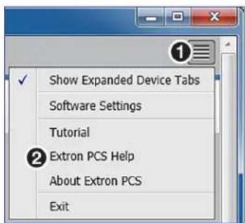
Updating Firmware Using PCS
Firmware for the SSP 200 can be updated using PCS. Updates to the SSP 200 firmware are made available periodically via the Extron website. You can find out what version of firmware is currently loaded on your SSP 200 by entering the SIS Q command via the RS-232, USB, or LAN interface (see Firmware Version/Part Number/Information Queries on page 69) or listed in Hardware Settings in PCS (see Hardware Settings on page 52).
Downloading the SSP 200 Firmware
To download the latest version of firmware for the SSP 200:
- Go to www.extron.com, and mouse over the DOWNLOAD tab (see figure 53, ①).

Figure 53. Download Tab
- Click the Firmware link (②) from the drop-down list. The Firmware page opens (see figure 54).

Figure 54. Firmware Page with the Alphabetic Navigation Bar
-
Click the letter S on the alphabetic navigation bar (①).
-
Scroll down the page until you locate the firmware for the SSP 200.
-
Click Download. The product download screen opens.
-
Enter the required user login information. An executable (.exe) file downloads to the PC. Run this program to place the firmware on the PC. Make a note of the folder where the firmware file was saved.
ATTENTION:
Loading the Firmware to the SSP 200
To load a new version of firmware to the SSP 200 using PCS:
- Connect your computer to the SSP 200 via either the device rear RS-232 or LAN port (see Rear Panel Features starting on page 6) or the front panel USB Config port (see Front Panel Features starting on page 11).
- If needed, download and install PCS to your computer (see Downloading PCS from the Extron Website on page 29).
- If needed, download the latest version of SSP 200 firmware to your computer (see Downloading the SSP 200 Firmware on page 58).
- Open PCS by clicking the desktop icon, if available or using your desktop Start menu to make the following selections: Start > All Programs > Extron Electronics > Extron Product Configuration Software.
The Product Configuration Software window opens to the Device Discovery screen (see figure 55).
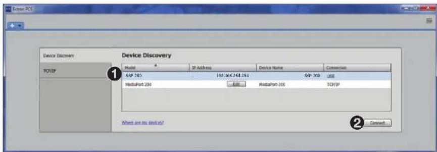
Figure 55. PCS Device Discovery Screen
- On the Device Discovery screen, select the SSP 200 (1).
- Click Connect (②).
- The Product Configuration Software opens to the main page (see figure 56). Click the device menu arrow next to the name of the device (1).

Figure 56. Accessing the Device PCS Menu
- The Device menu drops down (see figure 57). Click Update Firmware (①) and then Update Firmware to this Device... (②).

Figure 57. Update Firmware to this Device
- The Update Firmware window opens. Click Continue (see figure 58, 1).

Figure 58. Update Firmware Window
- The Update Firmware to this Device window opens. Click Open Firmware File... to locate and select the file.

Figure 59. Update Firmware Window
- An Explorer window opens. Navigate to the firmware file that has been downloaded to the connected PC.

Figure 60. Select Firmware File
ATTENTION:
Figure 61. Update Firmware
- After the upload is complete, a dialog box opens confirming that the update has been successful. Click Close. The software returns to the Device Discovery window (see figure 55 on page 59).
- Select the SSP 200 from the Device Discovery menu. A connection must be re-established with the device before continuing to use the software.
- Click Connect, or double-click the device. The device reconnects to the software.
NOTE: The original factory-installed firmware is permanently available on the SSP 200. If the attempted firmware upload fails for any reason, the device reverts to the factory version.
SIS Configuration and Control
This section describes Simple Instruction Set (SIS) command programming and control of the SSP 200, including:
- Connection Options
• Host-to-device Communications
• Using the Command and Response Tables
• Command and Response Tables
Connection Options
The SSP 200 can be configured and controlled using SIS commands or internal web pages. Configure and control the SSP 200 remotely via a host computer or other device (such as a control system) by connecting to the rear panel RS-232 port, LAN port, or the front panel USB Config port of the SSP device.
RS-232 Port
The SSP 200 has a rear panel serial port (see figure 3 on page 6) that can be connected to a host device such as a computer running the Extron DataViewer utility. The port makes serial control of the SSP possible. Use the protocol information listed below to make the connection (see Host-to-device Communications on page 64).
RS-232 protocol defaults:
9600 baud
- no parity
- 1 stop bit
- 8 data bits
- no flow control
Front Panel Configuration Port
The USB mini-B port is located on the front panel (see figure 10 on page 11). Connect to a host computer for configuration using SIS commands with DataViewer, available at www.extron.com. To connect the SSP 200 to a host computer, download the USB driver, follow the on-screen instructions, and configure the SSP as required.
Ethernet (LAN) Port
The rear panel LAN connector (see figure 3 on page 6) on the device can be connected to an Ethernet LAN or WAN. Communications between the SSP 200 and the controlling device is via an SSH client using port 22023. The SIS commands and the actions of the SSP 200 are identical to the commands and actions the processor has when communicating with it via RS-232.
By default, Telnet communication on TCP port 23 is disabled on the SSP 200. You can use Telnet by setting the port using Dataviewer (see Connection Options on page 62) with SIS commands (see Set Telnet port map on page 71).
LAN port defaults:
DHCP: off
SSP 200 IP address: 192.168.254.254
Subnet mask: 255.255.0.0
Gateway IP address: 0.0.0.0
Ethernet Connection
The Ethernet cable can be terminated as a straight-through cable or a crossover cable and must be properly terminated for your application (see figure 7 on page 8 for the Ethernet connector pin assignment).
• Crossover cable — Direct connection between the computer and the SSP.
- Patch (straight) cable — Connection of the SSP to an Ethernet LAN.
Establish a network connection to a SSP 200 processor via an SSH client:
- Download the SSH client software.
- Open the SSH software.
- Enter the IP address of the SSP 200 in the Host Name or IP address field.
NOTE: If the local system administrators have not changed the value, the default IP address is 192.168.254.254.
- Enter 22023 in the Port field.
- The SSP 200 is password protected, so the appropriate administrator or user name and password must be entered.
a. Enter admin or user.
b. Enter the password next to the Password prompt).
- If the login and password are correct, the device responds with a copyright message including the copyright year, the name of the product, firmware version, part number, and the current date and time.
- If the login and password are incorrect, the login prompt returns. Enter the administrator or user name and password again.
NOTES:
- The SSP 200 is shipped password-protected. The factory configured passwords for all accounts on this device have been set to the device serial number
- In the event of a complete system reset, the passwords convert to the default, which is extron. New passwords must be configured to secure the device.
Connection Timeouts
The Ethernet link times out after a designated period of time with no communication. By default, this timeout value is 5 minutes, but the value can be changed.
NOTE: Extron recommends leaving the default timeout at 5 minutes and periodically issuing the Query (Q) command to keep the connection active. If there are long idle periods, disconnect the socket and reopen the connection when another command must be sent.
Verbose Mode
SSH and Telnet connections can be used to monitor for changes that occur, such as SIS commands from other SSH or Telnet sockets or serial port changes. For a session to receive change notices, the session must be in verbose mode 1 or 3 (see Verbose Mode on page 74). In verbose mode 1 or 3, the socket reports changes in messages that resemble SIS command responses. Front panel changes are also sent to users who are in verbose mode.
Tagged and Untagged Responses
When a query command is sent in verbose mode 0 or 1, only the “untagged” value is returned. When a query command is sent in other verbose modes, the response is “tagged” and resembles the response to a set command.
Example: The "View Specific Output Channel Trim" command EscV8SSP← is sent. The following responses appear depending on the verbose mode:
- Untagged (verbose 0 or 1): -10←, just the dB value with no other information.
- Tagged (verbose 2 or 3): SspV8*-10←, the type of query sent, the analog channel queried, and the dB value.
Host-to-device Communications
SIS commands consist of one or more characters per command field. They do not require special characters to begin or end the command sequence. Each response to an SIS command ends with a carriage return and a line feed (CR/LF = ←), which signals the end of the response character string. A string is one or more characters.
NOTE: Secure Shell (SSH) client connections may add an extra line feed in the final terminator in SIS responses, for example, standard is x11← and SSH is x11←.
Password Information
NOTE: The factory configured passwords for all accounts on this device have been set to the device serial number. In the event of a complete system reset, the passwords convert to the default, which is extron.
The ←Password: prompt requires a password (administrator level or user level) followed by a carriage return. The prompt is repeated if the correct password is not entered.
If the correct password is entered, the unit responds with ← Login Administrator← or ← Login User←, depending on the password entered. If passwords are the same for both administrator and user, the unit defaults to administrator privileges.
Error Responses
When the SSP is unable to execute the command, it returns an error response to the host. The error response codes and their descriptions are as follows:
| E10 – Unrecognized command | E18 – System timed out |
| E12 – Invalid port number | E22 – Busy |
| E13 – Invalid parameter (number is out of range) | E24 – Privilege violation |
| E14 – Not valid for this configuration | E26 – Maximum connections exceeded |
| E17 – Invalid command for signal type | E28 – Bad file name or file not found |
Using the Command and Response Tables
The Command and Response Tables begins on page 69. Symbols used in the table represent variables in the command and response fields. Command and response examples are shown throughout the table. The SIS commands are not case sensitive. The ASCII to Hex conversion table below is for use with the command and response table.
| ASCII to HEX Conversion Table | Esc | 1B | CR | ∅D | LF | ∅A | |||||||||
| space | 20 | ! | 21 | “ | 22 | # | 23 | $ | 24 | % | 25 | & | 26 | ‘ | 27 |
| ( | 28 | ) | 29 | * | 2A | + | 2B | 2C | - | 2D | . | 2E | / | 2F | |
| ∅ | 30 | 1 | 31 | 2 | 32 | 3 | 33 | 4 | 34 | 5 | 35 | 6 | 36 | 7 | 37 |
| 8 | 38 | 9 | 39 | : | 3A | ; | 3B | < | 3C | = | 3D | > | 3E | ? | 3F |
| @ | 40 | A | 41 | B | 42 | C | 43 | D | 44 | E | 45 | F | 46 | G | 47 |
| H | 48 | I | 49 | J | 4A | K | 4B | L | 4C | M | 4D | N | 4E | O | 4F |
| P | 50 | Q | 51 | R | 52 | S | 53 | T | 54 | U | 55 | V | 56 | W | 57 |
| X | 58 | Y | 59 | Z | 5A | [ | 5B | \ | 5C | ] | 5D | ^ | 5E | _ | 5F |
| 、 | 60 | a | 61 | b | 62 | c | 63 | d | 64 | e | 65 | f | 66 | g | 67 |
| h | 68 | i | 69 | j | 6A | k | 6B | I | 6C | m | 6D | n | 6E | o | 6F |
| p | 70 | q | 71 | r | 72 | s | 73 | t | 74 | u | 75 | v | 76 | w | 77 |
| x | 78 | y | 79 | z | 7A | { | 7B | | | 7C | } | 7D | ~ | 7E | DEL | 7F |
Figure 62. ASCII to Hex Conversion
NOTE: For commands and examples of computer or device responses used in this guide, the character “θ” is the number zero and “O” is the capital letter “o”.
Symbol Definitions
← = CR/LF (carriage return with line feed) (hex 0D 0A)
← or | = Soft carriage return (no line feed)
- = Space
Esc or W = Escape
[X1] = Firmware query
= Detailed version information (includes all 2Q, 3Q, and 4Q)
1 = Firmware version
2 = Final stage bootloader
3 = Factory base code version
4 = Updated firmware version
X4 = IP Timeout: The number of seconds before timeout on IP connections (min=1, max=65000 and default = 30 (300 seconds). If no data is received during the timeout period, the Ethernet connection is closed. Each step = 10 seconds.
11 = Baud rate: 300, 600, 1200, 1800, 2400, 3600, 4800, 7200, 9600, 14400, 19200, 28800, 38400, 57600, 115200 (default=9600)
X12 = Parity: Odd, Even, None, Mark, Space [only use the first letter] (default=N=None)
X13 = Data bits: 7, 8 (default=8)
X14 = Stop bits: 1, 2 (default=1)
X15 = Port type: 0=RS232, 1=RS422, 2=RS485 (default=0=RS232)
X16 = Flow Control: Hardware, Software, None [only use the first letter] (default=N=None).
X17 = Data Pacing [specified in milliseconds between bytes]: 0000 to 1000 (default=0 ms). For host port(s), this value is ignored – always returns 0.
X19 = GMT offset value: This represent hours and minutes (hh:mm) offset from Greenwich Mean Time.
X20 = DHCP status
= Off (default) 1 = On
21 = Unit name: A text string up to 63 characters drawn from the alphabet (A to Z), digits (0 to 9), and minus sign/hyphen (-).
X22 = Local date and time format: MM/DD/YY-HH:MM:SS
X23 = IP Address: xxx.xxx.xxx.xxx. Leading zeros in each of the 4 fields are optional in setting values and are suppressed in responses.
X24 = Hardware MAC address: 00-05-A6-xx-xx-xx
25 = Subnet mask: xxx.xxx.xxx.xxx. Leading zeros in each of the 4 fields are optional in setting values and are suppressed in responses.
X26 = NIC number: Network Interface Card number 1 or 2.
X27 = Prefix (subnet mask bits): Subnet 255.255.0.0 is represented as a prefix value of /16.
X28 = Date/Time returned in 7 Hex bytes month, day, year, hour minutes, seconds, day of the week (1 begins on Sunday).
X29 = NTP service mode = Disable 1 = Enable
X30 = Default name: Combination of model-name and last 3 pairs of MAC address (for example: SSP-200-00-02-3D).
X31 = Password: Password: Up to 128 characters. All man-readable characters are permitted except "|". Password cannot be a single space. Passwords are case-sensitive.
X32 = Responds with 4 asterisks ( ^*** ) if password exists and empty if not, instead of actual password.
X33 = Connection security level
11 = User
12 = Administrator
X37 = Device temperature (degrees Celsius)
X38 = Verbose/response mode
    θ = Clear/none (IP default)
    1 = Verbose mode (USB default)
    2 = Tagged responses for queries
    3 = Verbose mode and tagged responses for queries
40 = Serial Host-control port mode: = Device Control (no SIS) 1 = Standard Host control (SIS - default) 2 = Disable Port
X41 = Connection status
1 = Connected
2 = Not Connected
X42 = Input number: 1 to 5.
X43 = EXP assignment (HDMI and analog inputs are unavailable for EXP assignment):
    θ = EXP off (default)
    2 = Input 2
    3 = Input 3
    4 = Input 4
X44 = EXP input channel pair:
| 1 = EXP Input 1 & 2 | 5 = EXP Input 9 & 10 |
| 2 = EXP Input 3 & 4 | 6 = EXP Input 11 & 12 |
| 3 = EXP Input 5 & 6 | 7 = EXP Input 13 & 14 |
| 4 = EXP Input 7 & 8 | 8 = EXP Input 15 & 16 |
X45 = Source format:
| 0 = Not present 7 = Dolby TrueHD ATMOS |
| 1 = Analog 8 = DTS or DTS 96/24 |
| 2 = PCM 9 = DTS-ES (96/24, Matrix, or Discrete) |
| 3 = Dolby Digital/EX 10 = DTS-HD High Resolution Audio |
| 4 = Dolby Digital Plus 11 = DTS-HD Master Audio |
| 5 = Dolby Digital Plus ATMOS 12 = DTS Express |
| 6 = Dolby TrueHD 13 = DTS:X |
X46 = Decoded Sampling Rate
| θ = None 4 = 88.2 kHz | |
| 1 = 32 kHz | 5 = 96 kHz |
| 2 = 44.1 kHz | 6 = 176.4 kHz |
| 3 = 48 kHz | 7 = 192 kHz |
X47 = Source Encoded Channels (Front, Center, Surround, Back, Subwoofer, Height)
| θ = None 8 = 4.1 | |
| 1 = 1.0 | 9 = 5.0 |
| 2 = 1.1 | 10 = 5.1 |
| 3 = 2.0 | 11 = 6.0 |
| 4 = 2.1 | 12 = 6.1 |
| 5 = 3.0 | 13 = 7.0 |
| 6 = 3.1 | 14 = 7.1 |
| 7 = 4.0 | |
X48 = Signal Status:
| θ = Signal not detected |
| 1 = Signal detected |
X49 = Input HDCP status:
| 0 = No source is detected |
| 1 = Source is detected with HDCP |
| 2 = Source detected without HDCP |
X50 = Enable or Disable:
| θ = Disable |
| 1 = Enable (default) |
X53 = HDMI Loop Out mode:
| 0 = No audio |
| 1 = Follow input |
| 2 = Downmix (Default) |
X54 = Output HDCP status:
| 0 = No sink detected |
| 1 = Sink detected with HDCP |
| 2 = Sink detected without HDCP |
X55 = Output HDCP mode:
| 1 = Auto: Encrypt as required by input. Continuous trials for HDMI sinks (Default) |
| 2 = Always Encrypt Output. Continuous trials for HDMI sinks |
☒57 = Output channel (channels 7 to 10 change depending on layout and downmix settings): 1 to 10 or 15 to 16.
Output Channels Table
| 1 Height Pair(no Downmix) | 2 Height Pairs(no Downmix) | 0 Height +Downmix | 1 Height Pair +Downmix | |
| 1 Left | front Left front Left front | front Left front | ||
| 2 Right | Front Right Front Right | Front Right Front | ||
| 3 Center | Center Center Center Center | |||
| 4 Subwoofer | Subwoofer Subwoofer | Subwoofer Subwoofer | ||
| 5 Left | Surround Left Surround | Left Surround Left Surround | ||
| 6 | Right Surround | Right Surround | Right Surround | Right Surround |
| 7 Left | Back Left | Height Front Left Back | Left Height Front | |
| 8 | Right Back | Right Height Front | Right Back | Right Height Front |
| 9 | Left Height Front | Left Height Back | Downmix L | Downmix L |
| 10 | Right Height Front | Right Height Back | Downmix R | Downmix R |
X58 = dB value: -24 to 0 (default 0)
X60 = Audio Mute: θ = Mute off (default) 1 = Mute on
X62 = %: 0 to 100 (default 80)
X65 = dB value: -18 to +24 (default 0)
X67 = Executive mode number
θ = Unlock front panel (default)
1 = Lock front panel
2 = Limit front panel to volume control
3 = Limit front panel to input selection
X77 = Slot number: 1 = HDMI input 2 = Loop Thru
X78 = 128 or 256 byte EDID raw HEX (text form) from currently assigned EDID.
X79 = Native resolution and refresh rate from currently assigned EDID, for example: 1920x1080 @ 60 Hz.
X81 = Connection status:
θ = Not connected
1 = Connected
X89 = Offset: 0-3000, 10x time value, from 0.0 to 300.0 milliseconds
X90 = Mono output mode:
1 = Center channel only (default)
2 = Front left and right only
X93 = Subwoofer mode:
θ = All off
1 = LFE (SUB) (default)
X98 = Listening mode:
1 = Auto (follow source) 5 = Mono to all
2 = Stereo 6 = Dolby Surround (Upmixer)
3 = Mono 7 = DTS Neural: X (Upmixer)
4 = Stereo to all
X109 = Volume level: 0 to 100 (-100 dB to 0 dB)
X111 = Analog input gain: -18 to +24 dB
X112 = Clip status:
θ = Off (no clipping)
1 = On (clipping)
X120 = Text - up to 64 characters
X121 = SNMP Trap target number (1 to 3)
X122 = SNMP Trap version for target (2 or 3)
NOTE: Unless otherwise indicated, commands are not case-sensitive.
Command and Response Tables
| Command SIS Command (Host to Device) | Response (Device to Host) | Additional Description | |
| Firmware Version/Part Number/Information Queries | |||
| Query model name | 1I | SSP•200← | |
| Verbose modes 2/3 | Inf01*SSP•200← | ||
| Query model description | 2I | Surround•sound•processor← | |
| Verbose modes 2/3 | Inf02*Surround•sound•processor← | ||
| Query firmware version | Q | {version x.xx}← | |
| Verbose modes 2/3 | Ver01 {*version x.xx}← | ||
| Query firmware version (advanced) | X2Q | {Specific version info}← | |
| Verbose modes 2/3 | VerX1 {*Specific version info}← | ||
| Query firmware version (w/build) | *Q | {version x.xx.xxxx}← | |
| Verbose modes 2/3 | Bld{version x.xx.xxxx}← | ||
| Query Kernel/Library version | **Q | {version x.xx.xxxxLX}← | |
| Verbose modes 2/3 | Lib{version x.xx.xxxxLX}← | ||
| Query system messaging version | ***Q | {version}← | |
| Verbose modes 2/3 | Idv{version x.xx}← | ||
| Query part number | N | ZZ-zzzz-zz← | |
| Verbose modes 2/3 | Pnozz-zzzz-zz← | ||
| KEY: X1 = Firmware query θ = Detailed version information (includes all 2Q, 3Q, and 4Q) 1 = Firmware version2 = Final Stage bootloader version 3 = Factory Base Code version 4 = Updated Firmware version | |||
Ethernet Data Port
| Set current connector port timeout | Esc0*X4TC← Pti0*X4← |
| View current connector port timeout | Esc0TC← X4← |
| Set global IP port timeout | Esc1*X4TC← Pti1*X4← |
| View global IP port timeout | Esc1TC← X4← |
| KEY: | × 4 = IP Timeout; The number of seconds before timeout on IP connections (min=1, max =65000 and default = 30 (300 seconds). If no data is received during the timeout period, the Ethernet connection is closed. Each step = 10 seconds. |
Serial Data Port (including Device control and Host control ports)
| Configure parameters | Esc1*X11X12X13X14CP← | Cpn1•CcpX11X12X13X14← |
| View parameters | Esc1CP← X11X12X13X14← | |
| Configure mode | Esc1*X15CY← | Cpn1•CtyX15← |
| View mode | Esc1CY← X15← | |
| Configure flow control | Esc1*X16X17CF← | Cpn1•CflX16X17← |
| View flow control | Esc1CF← X16X17← |
| KEY: | × 11 = Baud rate: 300, 600, 1200, 1800, 2400, 3600, 4800, 7200, 9600, 14400, 19200, 28800, 38400, 57600, 115200 (default=9600) |
12 = Parity: Odd, Even, None, Mark, Space [only use the first letter] (default = N = None)
X13 = Data bits: 7, 8 (default=8)
X14 = Stop bits: 1, 2 (default=1)
X15 = Port type: θ=RS232 1=RS422 2=RS485 (default=θ=RS232)
X16 = Flow Control: Hardware, Software, None [only use the first letter] (default=N=None)
X17 = Data Pacing [specified in milliseconds between bytes]: 0000 - 1000 (default=0 ms).
For host port(s), this value is ignored - always returns .
| Command SIS Command (Host to Device) | Response (Device to Host) | Additional Description | |
| IP Setup Commands | |||
| Set Unit name | EscX21CN← Ipn•X21← | ||
| Set Unit name to factory default | Esc•CN← Ipn•X30← | ||
| View Unit name | EscCN← X21← | ||
| Set date/time | EscX22CT← Ipt•X22← | ||
| View date/time | EscCT← X22← | ||
| Viiew date/time in Hex | Esc*CT← X28← | ||
| View GMT offset | EscCZ← Verbose modes 2/3 | X19← IpzX19← | |
| Set DHCP on | Esc1DH← Idh1← | ||
| Set DHCP off | Esc0DH← Idh0← | ||
| View DHCP mode | EscDH← X20← | ||
| Set IP address | EscX23CI← Ipi•X23← | ||
| View IP address | EscCI← X23← | ||
| View hardware address (MAC) | EscCH← Verbose modes 2/3 | X24← Iph•X24← | |
| Set subnet mask | EscX25CS← Ips•X25← | ||
| View subnet mask | EscCS← X25← | ||
| Set gateway IP address | EscX23CG← Ipg•X23← | ||
| View gateway IP address | EscCG← X23← | ||
| Set IP | Esc1*X23CISG← | Cisg•1*X23/X27*X23← | |
| Set IP/Subnet | Esc1*X23*X25CISG← | Cisg•1*X23/X27*X23← | |
| Set IP/Subnet/Gateway | Esc1*X23*X25*X23CISG← | Cisg•1*X23/X27*X23← | |
| View IP/Subnet/Gateway (all) | Esc1CISG← Verbose modes 2/3 | X23/X27*X23← | |
| Set DNS Server IP address | EscX23DI← Ipd•X23← | ||
| View DNS Server IP address | EscDI← Verbose modes 2/3 | X23← | |
| View connection listing | EscCC← Verbose modes 2/3 | {Number of connections}← Icc{Number of connections}← | |
| View device info | EscBC← | nullnullnull<6-byte MAC address in binary> | |
| KEY: X19=GMT offset value: This represent hours and minutes (hh:mm) offset from Greenwich Mean Time (GMT).X20=DHCP status: θ = Off (default) 1 = OnX21=Unit name: A text string up to 63 characters drawn from the alphabet (A-Z), digits (0-9), and minus sign/hyphen (-).X22=Local date and time format: MM/DD/YY-HH:MM:SSX23=IP Address: xxx.xxx.xxx.xxx. Leading zeros in each of the 4 fields are optional in setting values and are suppressed in responses.X24=Hardware MAC address: 00-05-A6-xx-xx-xxX25=Subnet mask: xxx.xxx.xxx.xxx. Leading zeros in each of the 4 fields are optional in setting values and are suppressed in responses.X27=Prefix (subnet mask bits); Subnet 255.255.0.0 is represented as a prefix value of /16.X28=Date/Time returned in 7 Hex bytes month, day, year, hour minutes, seconds, day of the week (1 begins on Sunday).X30=Default name: Combination of model-name and last 3 pairs of MAC address (for example: SSP-200-01-23-4D).Network Time Protocol (NTP) | |||
| Enable NTP to set the time | Esc1NTEN← Nten1← | ||
| Disable NTP | Esc0NTEN← Nten0← | ||
| Sync NTP now | Esc2NTEN← Nten2← | ||
| View NTP status | EscNTEN← X29← | ||
| Set NTP IP address | EscX23NTIP← NtipX23← | ||
| Set NTP IP address to default | Esc•NTIP← Ntip← | ||
| View NTP IP address | EscNTIP← X23← | ||
| Set NTP port map | EscN{port#}PMAP← PmapN{port#}← | ||
| Reset NTP port map | EscN123PMAP← PmapN00123← | ||
| Disable NTP port | EscN0PMAP← PmapN00000← | ||
| View NTP port map | EscNPMAP← {port#}← | ||
| KEY: X23 = IP Address: xxx.xxx.xxx.xxx. Leading zeros in each of the 4 fields are optional in setting values and are suppressed in responses.X29 = NTP service mode: θ = Disable 1 = Enable | |||
| Port Assignment | |||
| Set Telnet port map | Esc{port#}MT← Pmt{port#}← | ||
| Reset Telnet port map | Esc23MT← Pmt00023← | ||
| Disable Telnet port | Esc0MT← Pmt00000← | ||
| View Telnet port map | EscMT← {port#}← | ||
| Set Web port map | Esc{port#}MH← Pmh{port#}← | ||
| Reset Web port map | Esc80MH← Pmh00080← | ||
| Disable Web port | Esc0MH← Pmh00000← | ||
| View Web port map | EscMH← {port#}← | ||
| Set SNMP port map | EscA{port#}PMAP← PmapA{port#}← | ||
| Reset SNMP port map | EscA161PMAP← PmapA00161← | ||
| Disable SNMP port | EscA0PMAP← PmapA00000← | ||
| View SNMP port map | EscAPMAP← {port#}← | ||
| Set SSH port map | EscB{port#}PMAP← PmapB{port#}← | ||
| Reset SSH port map | EscB22023PMAP← PmapB22023← | ||
| Disable SSH port | EscB0PMAP← PmapB00000← | ||
| View SSH port map | EscBPMAP← {port#}← | ||
| Set SSL port map | EscS{port#}PMAP← PmapS{port#}← | ||
| Reset SSL port map | EscS443PMAP← PmapS00443← | ||
| Disable SSL port | EscS0PMAP← PmapS00000← | ||
| View SSL port map | EscSPMAP← {port#}← | ||
| Set FTP port map | EscF{port#}PMAP← PmapF{port#}← | ||
| Reset FTP port map | EscF21PMAP← PmapF00021← | ||
| Port Assignment (continued) | |||
| Disable FTP port | EscF0PMAP← PmapF00000← | ||
| View FTP port map | EscFPMAP← {port#}← | ||
| Set TFTP port map | EscT{port#}PMAP← PmapT{port#}← | ||
| Reset TFTP port map | EscT69PMAP← PmapT00069← | ||
| Disable TFTP port | EscT0PMAP← PmapT00000← | ||
| View TFTP port map | EscTPMAP← {port#}← | ||
| Simple Network Management Protocol (SNMP) | |||
| Set unit contact | EscC×120SNMP← SnmpC*×120← | ||
| Set unit contact to default | EscC•SNMP← SnmpC*Not•Specified← | ||
| View unit contact | EscCSNMP← ×120← | ||
| Set unit location | EscL×120SNMP← SnmpL*×120← | ||
| Set unit location to default | EscL•SNMP← SnmpL*Not•Specified← | ||
| View unit location | EscLSNMP← ×120← | ||
| Set community public (read-only) | EscP×120SNMP← SnmpP*×120← | ||
| Set community public to default | EscP•SNMP← SnmpP*public← | ||
| View community public | EscPSNMP← ×120← | ||
| Set community private (read/write) | Esc××120SNMP← SnmpX*×120← | ||
| Set community private to default | EscSnmpX*×120← SnmpX*private← | ||
| View community private | EscXSNMP← ×120← | ||
| Enable SNMP access and traps | EscE1SNMP← SnmpE*1← | ||
| Disable SNMP access and traps | EscE0SNMP← SnmpE*0← | ||
| View SNMP access setting | EscESNMP← ×29← | ||
| Set trap target | EscTX120,×121*×23*×122 SNMP← SnmpT*×120,×121*×23*×122← | ||
| Remove trap target | EscTX121*0SNMP← SnmpT*,×121*0.0.0.0*0← | ||
| View trap target | EscTX121SNMP← ×120,×23*×122← | ||
| KEY: X23 = IP Address: xxx.xxx.xxx.xxx . Leading zeros in each of the 4 fields are optional in setting values and are suppressed in responses.X29 = NTP service mode: θ = Disable 1 = EnableX120 = Text - up to 64 charactersX121 = SNMP Trap target number (1 to 3)X122 = SNMP Trap version for target (2 or 3)Password and Security Settings | |||
| Set admin password | EscX31CA← Ipa•X32← | ||
| Clear admin password | Esc•CA← Ipa•← | ||
| View admin password | EscCA← X32← | ||
| Set user password | EscX31CU← Ipu•X32← | ||
| Clear user password | Esc•CU← Ipu•← | ||
| View user password | EscCU← X32← | ||
| Query session security level | EscCK← Verbose modes 2/3 | X33← Pv1X33← | |
| KEY: X31 = Password: Up to 128 characters. All man-readable characters are permitted except “|”. Password cannot be a single space. Passwords are case-sensitive. The factory configured password for this device is set to the device serial number. When performing a factory reset, the password is set to the default password, which isextron. X32 = Responds with 4 asterisks (****) if password exists and empty if not, instead of actual password. X33 = Connection security level: 11 = User 12 = Administrator | |||
| Directories | |||
| Change/create directory | Escpath/directory/CJ← | Dir•path/directory/← | |
| Back to root directory | Esc/CJ← Dir•/← | ||
| Up one directory | Esc..CJ← | Dir•path/directory/← | |
| View current directory | EscCJ← | path/directory/← | |
| File Commands | |||
| Erase user-supplied web page/file | EscfilenameEF← | Del1filename← | |
| Erase current directory and contained files | Esc/EF← Ddl← | ||
| Erase current directory and subdirectories | Esc//EF← Ddl← | ||
| List files from current directory | EscDF← | filename•date/time•length← | |
| Load file to user flash memory | Esc+UFfilesize, filename← | Upl← | |
| Retrieve file from user flash memory | EscfilenameSF← | {responds with 4-bytes of file-size + raw unprocessed data in file} | |
| Backup/Restore Box Configuration | |||
| Save box configuration (to filesystem) | Esc1*{config type}XF← | Cfg1*{config type}← | |
| Restore box configuration | Esc0*{config type}XF← | Cfg0*{config type}← | |
| Command SIS Command (Host to Device) | Response (Device to Host) | Additional Description |
| Miscellaneous | ||
| Reboot system Esc1BOOT← Boot1← | ||
| Reboot network Esc2BOOT← Boot2← | ||
| View temperature Esc20STAT← X37← | ||
| KEY: X37 = Device temperature (degrees Celsius). | ||
| Verbose Mode | ||
| Set verbose mode EscX38CV← VrbX38← | ||
| View verbose mode EscCV← X38← | ||
| NOTE: Verbose mode reverts back to default in the event of a power cycle, disconnect from SSH client, or disconnect from the Ethernet. | ||
| KEY: X38 = Verbose/response mode: 0 = Clear/none (IP default) 1 = Verbose mode (USB default)2 = Tagged responses for queries 3 = Verbose mode and tagged responses for queries | ||
| SIS over SSH (port 22023) | ||
| Enable Echo Esc1ECHO← Echo1← | Returns command entered with response. | |
| Disable Echo Esc0ECHO← Echo0← | Returns response only. | |
| View Echo status EscECHO← X50← | ||
| NOTE: Secure Shell (SSH) client connections may add an extra line feed in the final terminator in SIS responses, for example, standard is X11and SSH is X11← | ||
| KEY: X50 = Enable or disable: 0 = Disable 1 = Enable (default) | ||
| Serial Host Control Port Mode | ||
| Standard Host control Esc1*1HSTM← HstmX40*1← | ||
| Device control (no SIS) Esc1*2HSTM← HstmX40*2← | ||
| Disable port Esc1*0HSTM← HstmX40*0← | ||
| Query port mode Esc1HSTM← X40← | ||
| KEY: X40 = Serial Host-control port mode: 0 = Device Control (no SIS) 1 = Standard Host control (SIS - default) 2 = Disable Port | ||
| Command SIS Command (Host to Device) | Response (Device to Host) | Additional Description | |
| Miscellaneous | |||
| Reboot system | Esc1B00T← Boot1← | ||
| Reboot network | Esc2B00T← Boot2← | ||
| View temperature | Esc20STAT← X37← | ||
| KEY: X37 = Device temperature (degrees Celsius). | |||
| Verbose Mode | |
| Set verbose mode | EscX38CV← VrbX38← |
| View verbose mode | EscCV← X38← |
| NOTE: Verbose mode reverts back to default in the event of a power cycle, disconnect from SSH client, or disconnect from the Ethernet. | |
| KEY: X38 = Verbose/response mode: 0 = Clear/none (IP default) 1 = Verbose mode (USB default)2 = Tagged responses for queries 3 = Verbose mode and tagged responses for queries | ||
| SIS over SSH (port 22023) | ||
| Enable Echo | Esc1ECHO← Echo1← | Returns command entered with response. |
| Disable Echo | Esc0ECHO← Echo0← | Returns response only. |
| View Echo status | EscECHO← X50← | |
| NOTE: Secure Shell (SSH) client connections may add an extra line feed in the final terminator in SIS responses, for example, standard is X11and SSH is X11←← |
| KEY: X50 = Enable or disable: θ = Disable 1 = Enable (default) |
| Serial Host Control Port Mode | ||||
| Standard Host control (SIS) | Esc1*1HSTM← HstmX40*1← | |||
| Device control (no SIS) | Esc1*2HSTM← HstmX40*2← | |||
| Disable port | Esc1*0HSTM← HstmX40*0← | |||
| Query port mode | Esc1HSTM← X40← | |||
| KEY: X40 = Serial Host-control port mode: θ = Device Control (no SIS) 1 = Standard Host control (SIS - default) 2 = Disable Port | ||||
| Command SIS Command (Host to Device) | Response (Device to Host) | Additional Description | |
| Input Selection | |||
| Select audio input | X42AudX42← | ||
| View audio input | Verbose modes 2/3 | X42←AudX42← | |
| Set EXP input assignment | EscEX43SSP←SspEX43← | ||
| View EXP input assignment | EscESSP←Verbose modes 2/3 | X43←SspEX43← | |
| Set EXP input channel pair | EscPXX44SSP←SspPXX44← | ||
| View EXP input channel pair | EscPSSP←Verbose modes 2/3 | X44←SspPXX44← | |
| View audio input source | 33IVerbose modes 2/3 | SrcFormat•X45•Sampling•X46•EnChan•X47←Inf33SrcFormat•X45•Sampling•X46•EnChan•X47← | |
| View audio signal presence (selected input) | EscOLS←Verbose modes 2/3 | X48←In00•X48← | |
| View input HDCP status | EscIHDCP←Verbose modes 2/3 | X49←Hdcp1X49← | |
| Set HDCP authorization | EscEX50HDCP←HdcpEX50← | ||
| View HDCP authorization status | EscEHDCP←Verbose modes 2/3 | X50←HdcpEX50← | |
| View incoming line count | 34IVerbose modes 2/3Example: | **************************************************************************************************** | ************************************************************************************************** |
KEY: X42 = Input number: 1 to 5
X43 = EXP assignment (HDMI and analog inputs are unavailable for EXP assignment):
= EXP off (default) 2 = Input 2 3 = Input 3 4 = Input 4
X44 = EXP input channel pair:
1 = EXP Input 1 & 2 2 = EXP Input 3 & 4 3 = EXP Input 5 & 6 4 = EXP Input 7 & 8
5 = EXP Input 9 & 10 6 = EXP Input 11 & 12 7 = EXP Input 13 & 14 8 = EXP Input 15 & 16
X45 = Source format:
= Not present 1 = Analog 2 = PCM 3 = Dolby Digital/EX 4 = Dolby Digital Plus
5 = Dolby Digital Plus ATMOS 6 = Dolby TrueHD 7 = Dolby TrueHD ATMOS 8 = DTS or DTS 96/24
9 = DTS-ES (96/24, Matrix, or Discrete) 10 = DTS-HD High Resolution Audio 11 = DTS-HD Master Audio
12 = DTS Express 13 = DTS:X
X46 = Decoded Sampling Rate:
= None 1 = 32 kHz 2 = 44.1 kHz 3 = 48 kHz 4 = 88.2 kHz 5 = 96 kHz
6 = 176.4 kHz 7 = 192 kHz
X47 = Source Encoded Channels (Front, Center, Surround, Back, Subwoofer, Height):
= None 1 = 1.0 2 = 1.1 3 = 2.0 4 = 2.1 5 = 3.0
6 = 3.1 7 = 4.0 8 = 4.1 9 = 5.0 10 = 5.1 11 = 6.0
12 = 6.1 13 = 7.0 14 = 7.1
X48 = Signal Status: = Signal not detected 1 = Signal detected
X49 = Input HDCP status: = No source is detected 1 = Source is detected with HDCP 2 = Source detected without HDCP
X50 = Enable or Disable: θ = Disable 1 = Enable (default)
| Command SIS Command (Host to Device) | Response (Device to Host) | Additional Description | |
| Outputs | |||
| Set HDMI Loop Thru | EscX53LOUT← LoutX53← | ||
| View HDMI Loop Thru | EscLOUT← | X53← | |
| Verbose modes 2/3 | LoutX53← | ||
| View Output HDCP Status | EscOHDCP← | X54← | |
| Verbose modes 2/3 | Hdcp0X54← | ||
| Set Output HDCP Mode | EscSXX55HDCP← HdcpSXX55← | ||
| View Output HDCP Mode | EscSHDCP← | X55← | |
| Verbose modes 2/3 | HdcpSXX55← | ||
| KEY: X53 = HDMI Loop Out mode: 0 = No audio 1 = Follow input 2 = Downmix (Default)X54 = Output HDCP status: 0 = No sink detected 1 = Sink detected with HDCP 2 = Sink detected without HDCPX55 = Output HDCP mode: 1 = Auto: encrypt as required by input. Continuous trials for HDMI sinks. (Default)2 = Always Encrypt Output: Continuous trials for HDMI sinks | |||
| Level Control | |||
| Output Channel Trim Settings | |||
| Set specific output channel trim | EscVXX57*X58SSP← | SspVXX57*X58← | |
| View specific output channel trim | EscVXX57SSP← | X58← | |
| Verbose modes 2/3 | SspVXX57*X58← | ||
| KEY: X57 = Analog output channel (channels 7-10 change depending on layout and downmix settings): 1 to 10 or 15 to 16(see Output Channels Table on page 68 for details).X58 = dB value: -24 to 0 (default 0) | |||
| Audio Mute | |||
| Mute all output channels (global mute) | 1Z | AmtX60← | Sets mute to on for all channels. |
| Unmute all output channels (global unmute) | 0Z | AmtX60← | Sets mute to off for all channels. |
| View global mute status | Z | X60← | Returns 1 when all outputs are muted. Returns 0 if any outputs are unmuted. |
| Mute specific channel | X57*1Z AmtX57*X60← | Sets mute to on for selected channel. | |
| Unmute specific channel | X57*0Z AmtX57*X60← | Sets mute to off for selected channel. | |
| View mute of specific channel | X57*Z X60← | Shows the mute status of the selected channel. | |
| KEY: X57 = Analog output channel (channels 7-10 change depending on layout and downmix settings): 1 to 12 or 15 to 16(see Output Channels Table on page 68 for details).X60 = Audio Mute: 0 = Mute off (default) 1 = Mute onVolume | |||
| Specify volume | X62V Vo1X62← | ||
| Increment volume (+) | +V | Vo1X62← | |
| Decrement volume (-) | -V | Vo1X62← | |
| View volume setting | V | X62← | |
| Verbose modes 2/3 | Vo1X62← | ||
| KEY: X62 = %: θ to 100 (default 80) | |||
| Analog Input Level | |||
| Set analog input gain level (input 5 only) | EscAX65SSP← SspAX65← | ||
| View analog input gain level (input 5 only) | EscASSP← | X65← | |
| Verbose modes 2/3 | SspAX65← | ||
| View clip status | 3S | X112← | |
| Verbose modes 2/3 | Sts3*X112← | ||
| KEY: X65 = dB value: -18 to +24 (default θ) X112 = Clip status: θ = Off (no clipping) 1 = On (clipping) | |||
| Executive Modes | |||
| Set Executive Mode | X67X ExeX67← | ||
| View Executive Mode | X | X67← | |
| Verbose modes 2/3 | ExeX67← | ||
| KEY: X67 = Executive mode number θ = Unlock front panel (default) 1 = Lock front panel 2 = Limit front panel to volume control 3 = Limit front panel to input selection. | |||
| EDID Minder | |||
| Import EDID (.bin) to input (store) slot | EscI X77,EDID← | EdidI X78← | Import EDID fromto input slot x77 |
| Export EDID (.bin) to PC | EscE X77,EDID← | EdidE X78← | Export EDID from EDID table slot x77 to |
| View EDID in HEX format | EscREDID← | X78← | EDID record: 128 or 256 Bytes (delivered as Hex) |
| Verbose modes 2/3 | EdidR X78← | ||
| View EDID native resolution | EscNEDID← | X79← | View native resolution & refresh rate of EDID from EDID table slot 1. Example: 1920x1080 @60.00Hz |
| Verbose modes 2/3 | EdidN X79← | ||
| KEY: X77 = Slot number: 1 = HDMI input 2 = Loop Thru X78 = 128 or 256 byte EDID raw HEX (text form) from currently assigned EDID X79 = Native resolution and refresh rate from currently assigned EDID, for example: 1920x1080 @60 Hz. | |||
| EXP Port | |||
| Get current device connection status | EscREXPP← | X81← | |
| Verbose modes 2/3 | ExppR X81← | ||
| KEY: X81 = Connection status: θ = Not connected 1 = Connected | |||
| Command SIS Command (Host to Device) | Response (Device to Host) | Additional Description | |
| Volume | |||
| Specify volume | X62V Vo1X62← | ||
| Increment volume (+) | +V | Vo1X62← | |
| Decrement volume (-) | -V | Vo1X62← | |
| View volume setting | V | X62← | |
| Verbose modes 2/3 | Vo1X62← | ||
| KEY: X62 = %: 0 to 100 (default 80) | |||
| Analog Input Level | |||
| Set analog input gain level (input 5 only) | EscAX65SSP← SspAX65← | ||
| View analog input gain level (input 5 only) | EscASSP← | X65← | |
| Verbose modes 2/3 | SspAX65← | ||
| View clip status | 3S | X112← | |
| Verbose modes 2/3 | Sts3*X112← | ||
| KEY: X65 = dB value: -18 to +24 (default 0) X112 = Clip status: 0 = Off (no clipping) 1 = On (clipping) | |||
| Executive Modes | |||
| Set Executive Mode | X67X ExeX67← | ||
| View Executive Mode | X | X67← | |
| Verbose modes 2/3 | ExeX67← | ||
| KEY: X67 = Executive mode number 0 = Unlock front panel (default) 1 = Lock front panel 2 = Limit front panel to volume control 3 = Limit front panel to input selection. | |||
| EDID Minder | |||
| Import EDID (.bin) to input (store) slot | EscI X77,EDID← | EdidI X78← | Import EDID fromto input slot x77 |
| Export EDID (.bin) to PC | EscE X77,EDID← | EdidE X78← | Export EDID from EDID table slot x77 to |
| View EDID in HEX format | EscREDID← | X78← | EDID record: 128 or 256 Bytes (delivered as Hex) |
| Verbose modes 2/3 | EdidR X78← | ||
| View EDID native resolution | EscNEDID← | X79← | View native resolution & refresh rate of EDID from EDID table slot 1. Example: 1920x1080 @60.00Hz |
| Verbose modes 2/3 | EdidN X79← | ||
| KEY: X77 = Slot number: 1 = HDMI input 2 = Loop Thru X78 = 128 or 256 byte EDID raw HEX (text form) from currently assigned EDID X79 = Native resolution and refresh rate from currently assigned EDID, for example: 1920x1080 @60 Hz. | |||
| EXP Port | |||
| Get current device connection status | EscREXPP← | X81← | |
| Verbose modes 2/3 | ExppR X81← | ||
| KEY: X81 = Connection status: 0 = Not connected 1 = Connected | |||
| Command SIS Command (Host to Device) | Response (Device to Host) | Additional Description | |
| Layouts and Speakers | |||
| Set lip-sync offset |  |  | |
| View lip-sync offset |  |  | |
 |  | ||
| Set mono output mode |  |  | |
| View mono output mode |  |  | |
 |  | ||
| KEY: X42 = Input number: 1 to 5X89 = Offset: 0 to 3000, 10x time value, from 0.0 to 300.0 millisecondsX90 = Mono output mode: 1 = Center channel only (default) 2 = Front left and right only | |||
| Subwoofer | |||
| Set subwoofer mode | EscJX93SSP← SspJX93← | ||
| View subwoofer mode | EscJSSP←Verbose modes 2/3 | X93←SspJX93← | |
| KEY: X93 = Subwoofer mode: 0 = Off 1 = LFE (SUB) (default). | |||
| Surround | |||
| View listening mode | EscLX42*X45SSP←Verbose modes 2/3 | X98←SspLX42*X45*X98← | |
| KEY: X42 = Input number: 1 to 5X45 = Source format: 0 = Not present 1 = Analog 2 = PCM 3 = Dolby Digital 4 = Dolby Digital Plus5 = Dolby Digital Plus ATMOS 6 = Dolby TrueHD 7 = Dolby TrueHD ATMOS 8 = DTS or DTS 96/249 = DTS-ES (96/24, Matrix, or Discrete) 10 = DTS-HD High Resolution Audio 11 = DTS-HD Master Audio12 = DTS Express 13 = DTS:XX98 = Listening mode: 1 = Auto (follow source) 2 = Stereo 3 = Mono 4 = Stereo to all 5 = Mono to all6 = Dolby Surround (Upmixer) 7 = DTS Neural: X (Upmixer) | |||
| Resets | |||
| System reset (factory default) | EscZXXX← Zpx← | ||
| Absolute reset including IP settings | EscZQQQ← Zpq← | ||
Subwoofer
| Set subwoofer mode | EscJX93SSP← | SspJX93← |
| EscJSSP← | X93← |
| Verbose modes 2/3 | SspJX93← |
Surround
| View listening mode | EscLX42*X45SSP← | X98← |
| Verbose modes 2/3 | SspLX42*X45*X98← |
| X45 = Source format: θ = Not present 1 = Analog 2 = PCM 3 = Dolby Digital 4 = Dolby Digital Plus5 = Dolby Digital Plus ATMOS 6 = Dolby TrueHD 7 = Dolby TrueHD ATMOS 8 = DTS or DTS 96/249 = DTS-ES (96/24, Matrix, or Discrete) 10 = DTS-HD High Resolution Audio 11 = DTS-HD Master Audio12 = DTS Express 13 = DTS:X |
| X98 = Listening mode: 1 = Auto (follow source) 2 = Stereo 3 = Mono 4 = Stereo to all 5 = Mono to all6 = Dolby Surround (Upmixer) 7 = DTS Neural: X (Upmixer) |
Resets
| System reset (factory default) | EscZXXX← Zpx← |
| Absolute reset including IP settings | EscZQQQ← Zpq← |
| Description Response (Device to Host) | |
| Unsolicited Responses | |
| Audio Input | AudX42← |
| Audio input source change | Inf33SrcFormat•X45•Sampling•X46•EnChan•X47← |
| Volume level | VolX109← |
| Input listening mode | SspLX42*X98← |
| Analog level adjustment | SspA X111← |
| Analog input clip status | Sts3*X112← |
| Current device EXP connection status | ExppR X41← |
| EXP input assignment | SspE X43← |
| KEY: X41 = Connection Status: 1 = Connected 2 = Not Connected. X42 = Input number: 1 to 5. X43 = EXP assignment (HDMI and analog inputs are unavailable for EXP assignment): θ = EXP off (default) 2 = Input 2 3 = Input 3 4 = Input 4. X45 = Source format: θ = Not present 1 = Analog 2 = PCM 3 = Dolby Digital 4 = Dolby Digital Plus 5 = Dolby Digital Plus ATMOS 6 = Dolby TrueHD 7 = Dolby TrueHD ATMOS 8 = DTS or DTS 96/24 9 = DTS-ES (96/24, Matrix, or Discrete) 10 = DTS-HD High Resolution Audio 11 = DTS-HD Master Audio 12 = DTS Express 13 = DTS:X X46 = Decoded Sampling Rate: θ = None 1 = 32 kHz 2 = 44.1 kHz 3 = 48 kHz 4 = 88.2 kHz 5 = 96 kHz 6 = 176.4 kHz 7 = 192 kHz X47 = Source Encoded Channels (Front, Center, Surround, Back, Subwoofer, Height): θ = None 1 = 1.0 2 = 1.1 3 = 2.0 4 = 2.1 5 = 3.0 6 = 3.1 7 = 4.0 8 = 4.1 9 = 5.0 10 = 5.1 11 = 6.0 12 = 6.1 13 = 7.0 14 = 7.1 X98 = Listening mode: 1 = Auto (follow source) 2 = Stereo 3 = Mono 4 = Stereo to all 5 = Mono to all 6 = Dolby Surround (Upmixer) 7 = DTS Neural: X (Upmixer) X109 = Volume level: θ to 100 (0% to 100%) X111 = Analog input gain: -18 to +24 dB X112 = Clip status: θ = Off (no clipping) 1 = On (clipping) | |
Internal Web Page
This section gives an overview of the SSP 200 internal web page. Topics include:
• Overview of the Internal Web Page
- Accessing the Internal Web Page
• Web Page Components
Overview of the Internal Web Page
The SSP 200 internal web pages provide the software user interface for operating and configuring the SSP 200 via a PC on the same network. This allows you to:
• View and edit the device name
• View input and output details
• View and edit the network settings
- Update the firmware version
- Set the date and time either manually or to sync with a connected PC
Connection is made via a LAN or WAN connection through the rear panel LAN (RJ-45) port, using a web browser such as Microsoft® Edge®, Mozilla® Firefox®, Google Chrome™, or Apple® Safari®.
Accessing the Internal Web Page
To access the internal web pages:
- Using an RJ-45 cable, connect the device to a LAN via the rear panel LAN port (see Rear Panel Features on page 6).
- Launch the web browser on your computer.
- Enter the device IP address into a web browser address bar. If the IP address has not been changed, the default address is 192.168.254.254.
- Press the keyboard
key. The SSP 200 web page requires user authentication to continue. Click in the Password field and enter the appropriate administrator or user password. Click OK.
NOTE: The factory configured passwords for all accounts on this device have been set to the device serial number. Passwords are case sensitive. If the SSP 200 is reset, the passwords revert to the default, which is extron.
Web Page Components
The SSP 200 web page (see figure 63) has eight panels:
1 Device Info
⑤ Outputs
② Device Status
6 RS-232
③ Network Settings
7 Roles and Permissions
4 Inputs
8 Firmware

Figure 63. Web Page
Device Info
The Device Info panel shows the current device name, description, part number, and manufacturer. You can change the device name by first clicking EDIT ① on the bottom of the Device Info panel.
This opens the Device Info Settings dialog box (see figure 64).
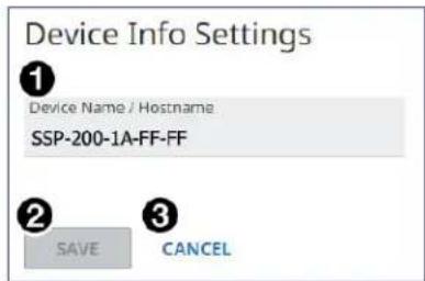
Figure 64. Device Info Settings Dialog Box
To change the device name:
-
Click into the Device Name field (see figure 64, ①, on the previous page).
-
Enter a desired name.
NOTE: The name can have alphanumeric characters and hyphens only. A hyphen cannot be the first or last character. An incorrect name is ignored and the current name is not changed.
- Click SAVE (②). The new name is applied, the dialog box closes, and the device name in the Network Settings panel is also updated with the new name.
Click CANCEL (3) to exit the process without making any changes.
NOTE: The default name is a combination of the model name and last three pairs of the MAC address (for example, SSP-200-18-FF-FF).
Device Status
The Device Status panel (see figure 64, ②, on the previous page) displays the date, time, and time zone for the connected SSP 200, and allows the user to either synchronize the date and time to a connected PC or set the date and time manually.
To synchronize to the connected PC:
- On the Device Status panel, click SYNC TO PC.
- If successful, you see a confirmation message and the current Date, Time, and Timezone on the Device Status panel.
To set the information manually:
- Click EDIT on the Device Status panel.
The Device Status Settings dialog box appears (see figure 65). - Change Date and Time (①) and the Timezone (②) as appropriate.
- Click SAVE (③) when done. You see the changes on the Device Status panel if the update has been successful.
Click CANCEL (4) to exit the process without making any changes.

Figure 65. Device Status Settings
Network Settings
The Network Settings panel shows the current network settings for the SSP 200 (see figure 63 on page 81). To change the settings, click EDIT to access the Network Settings dialog box (see figure 66).

Figure 66. Network Settings Dialog Box
To configure the settings for use with DHCP:
- Set the DHCP slider (①) to On.
- Click SAVE (5). An IP address is automatically assigned to the device. Contact your IT administrator for more information.
Click CANCEL (6) to exit the process without making any changes.
To configure the settings with a static IP address:
- Ensure the DHCP slider (①) is set to Off.
- In the IP Address field (②), enter an IP address for the device.
- In the Subnet field (③), enter the subnet mask for the device.
- In the Gateway field (4), enter the default gateway to be used.
- Click SAVE (⑤) to apply the changes, or click CANCEL (⑥) to exit the process without making any changes.
NOTE: The default TCP/IP settings are:
• IP address = 192.168.254.254
- Subnet Mask = 255.255.0.0
- Default Gateway = 0.0.0.0
Inputs
The Inputs panel displays the name and signal type of the active input as well as its HDCP status (see figure 63, 4, on page 81).
The following HDCP status indicators may be displayed for a connected input:
| Symbol Definition | |
| (2TDC) | The signal is HDCP encrypted. |
| (5SCT) | The signal is not encrypted. |
| No Signal There is no signal detected. | |
Click 4 MORE to see the full Inputs panel showing the remaining inputs (see figure 67). This panel is not user-configurable. Click the X on the top right of the panel to return to the main web page.

Figure 67. Inputs Panel
NOTE: Input audio format details are only available when an input is selected.
Outputs
This panel displays the status of the connected output (see figure 63, 5). This panel is not user-configurable.
The following status symbols may be displayed for the connected output:
| Symbol Definition | |
| twert | The signal is HDCP compliant. |
| trwt | The signal is not compliant. |
| No Signal No display is connected. | |
RS-232
This panel displays RS-232 information (see figure 63, 6, on page 81). This panel is not user-configurable.
Roles and Permissions
The Roles and Permissions panel on the main web page gives the user access to set the admin and user passwords for the SSP 200 (see figure 63, 7).
To change them, click EDIT in this panel. The Roles and Permission Settings dialog box opens (see figure 68).

Figure 68. Role and Permission Settings
Change each password field as applicable. Click SAVE (①) to apply the changes or CANCEL (②) to exit the process without making any changes.
NOTE: The factory configured passwords for all accounts on this device have been set to the device serial number. Passwords are case sensitive. if the SSP 200 is reset, the passwords revert to the default, which is extron.
The maximum length of a password is 128 characters. All human-readable characters are permitted except "I". Passwords are case-sensitive and cannot be a single space.
NOTES:
- Only an administrator can set the admin password.
- The default admin name is admin and the default user name is user.
- An indicator of the current login status is shown on the top right corner of the main screen.

Firmware
The Firmware panel (see figure 63, ⑧, on page 81) displays the current firmware version and when it was last updated to the device (see figure 69, ①).

Figure 69. Firmware Panel
NOTE: The latest firmware can be downloaded from the Extron website (see Downloading the SSP 200 Firmware on page 58).
To update the SSP 200 firmware version:
- Before starting, download the latest version of the firmware to your PC (see the note above).
- An executable (.exe) file is downloaded to the PC. Run this program to place the firmware on the PC for future use. Make a note of the folder where the firmware file was saved.
ATTENTION:
Figure 70. Selecting the Firmware File
- Click Open. The window closes and the Firmware panel opens showing the firmware file in the file name field (see figure 71, ①).
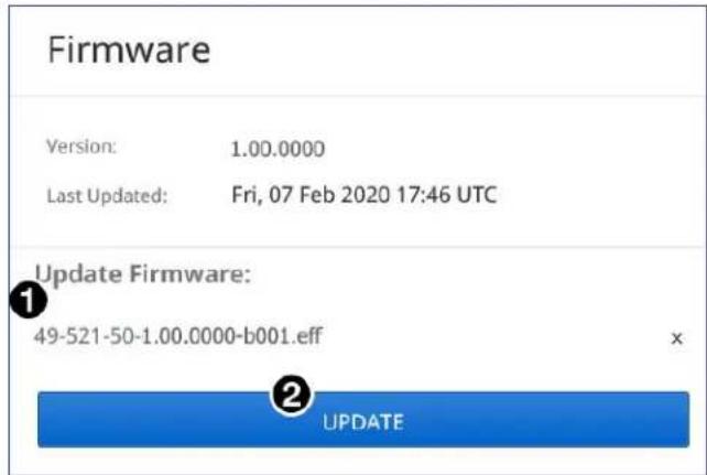
Figure 71. Firmware Panel - Update
- Click UPDATE (②). The firmware is uploaded to the connected device.
NOTE: The original factory-installed firmware is permanently available on the SSP 200. If the attempted firmware upload fails for any reason, the processor reverts to the factory version.
Extron Warranty
Extron warrants this product against defects in materials and workmanship for a period of three years from the date of purchase. In the event of malfunction during the warranty period attributable directly to faulty workmanship and/or materials, Extron will, at its option, repair or replace said products or components, to whatever extent it shall deem necessary to restore said product to proper operating condition, provided that it is returned within the warranty period, with proof of purchase and description of malfunction to:
USA, Canada, South America, and Central America:
Extron
1230 South Lewis Street
Anaheim, CA 92805
U.S.A.
Asia:
Extron Asia Pte Ltd
135 Joo Seng Road, #04-01
PM Industrial Bldg.
Singapore 368363
Singapore
Japan:
Extron Japan
Kyodo Building, 16 Ichibancho
Chiyoda-ku, Tokyo 102-0082
Japan
Europe:
Extron Europe
Hanzeboulevard 10
3825 PH Amersfoort
The Netherlands
China:
Extron China
686 Ronghua Road
Songjiang District
Shanghai 201611
China
Middle East:
Extron Middle East
Dubai Airport Free Zone
F13, PO Box 293666
United Arab Emirates, Dubai
Africa:
Extron South Africa
3rd Floor, South Tower
160 Jan Smuts Avenue
Rosebank 2196, South Africa
This Limited Warranty does not apply if the fault has been caused by misuse, improper handling care, electrical or mechanical abuse, abnormal operating conditions, or if modifications were made to the product that were not authorized by Extron.
NOTE: If a product is defective, please call Extron and ask for an Application Engineer to receive an RA (Return Authorization) number. This will begin the repair process.
USA: 714.491.1500 or 800.633.9876 Asia:
65.6383.4400
Europe: 31.33.453.4040 or 800.3987.6673
Japan: 81.3.3511.7655
Africa: 27.11.447.6162
Middle East: 971.4.299.1800
Units must be returned insured, with shipping charges prepaid. If not insured, you assume the risk of loss or damage during shipment. Returned units must include the serial number and a description of the problem, as well as the name of the person to contact in case there are any questions.
Extron makes no further warranties either expressed or implied with respect to the product and its quality, performance, merchantability, or fitness for any particular use. In no event will Extron be liable for direct, indirect, or consequential damages resulting from any defect in this product even if Extron has been advised of such damage.
Please note that laws vary from state to state and country to country, and that some provisions of this warranty may not apply to you.
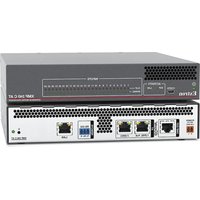
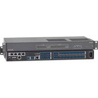
- Safety Instructions
- Safety Instructions • English
- FCC Class A Notice
- ATTENTION:
- Battery Notice
- Conventions Used in this Guide
- Notifications
- Software Commands
- Specifications Availability
- Extron Glossary of Terms
- Contents
- Introduction ...... 1
- Panel Features......6
- Speaker Setup 18
- Reference 24
- Product Configuration Software ...... 29
- SIS Configuration and Control ......62
- Internal Web Page 80
- Introduction
- About the SSP 200
- NOTES:
- SSP 200 Features
- Mounting
- Rack Mounting
- UL Guidelines for Rack Mounting
- Under-desk Mounting
- Panel Features
- Rear Panel Features
- Securing an HDMI Connector
- Front Panel Features
- Source Format
- • 2-Channel (2-CH):
- Input Selection
- Volume Adjustment
- Analog Input Gain Level
- System Reset
- Front Panel Security Lockout (Executive Mode)
- Connecting to the USB Port
- Click Next ( 4).
- Speaker Setup
- Speaker Placement
- Back Speakers
- Bass Management
- Speaker Settings
- Full Range
- Subwoofer
- Crossover Frequency
- Speaker Delay Settings
- Test Signals
- Output Channel Trim Settings
- Listening Mode Settings
- Equalization
- Reference
- Source Formats
- Dolby Digital Source Formats
- Dolby Digital (2/0, 2/0 Surround, 5.1, Surround EX)
- Dolby Digital Plus/Dolby Digital Plus Atmos
- Dolby TrueHD/Dolby TrueHD Atmos
- DTS Source Formats (DTS)
- DTS/DTS 96/24
- DTS ES (96/24, Matrix, Discrete)
- DTS-HD High Resolution Audio
- DTS Express
- DTS-HD Master Audio & DTS:X
- PCM Digital Source Format (PCM)
- 2-Channel Source Format (2CH)
- Analog
- Digital
- Sampling Frequency
- Listening Mode Options and Usage
- Listening Mode Options
- Auto
- Stereo
- Mono
- Stereo to All
- Mono to All
- Dolby Surround
- DTS Neural:X
- Product Configuration Software
- Downloading PCS from the Extron Website
- Using PCS Software
- Connecting to the SSP 200
- Main Menu
- I/O Panel
- Input/Output Config
- Input Configuration
- HDMI Input 1
- DMP EXP Input
- Analog Input 5
- Output Configuration
- HDMI Loop Out
- Listening Mode Setup
- EDID Minder
- EDID Minder Panels
- EDID Filters
- Applying a Filter
- Clearing Applied Filters
- Adding EDID to the Favorites Panel
- Importing EDID to the EDID Library
- Accessing the EDID library
- Accessing a non-factory default EDID into the EDID library
- EDID Assignment
- Assigning a Factory-Default Extron EDID
- Assigning a Non-Factory-Default EDID
- Assigning EDID from a connected output
- Searching for EDID by Name
- EDID Report
- Audio Config
- Speaker Configuration
- Speaker Delay
- Speaker Distance
- Two Person Setup
- Setup with a Real Time Analyzer (RTA) calibration tool
- Lip Sync Offset
- Test and Output Trim
- Test Signal Output
- Selecting test signal source
- Selecting speakers to be tested
- Speaker test sequence
- To run an automatic test sequence:
- To test the speakers manually:
- Output Trim
- Speaker Equalization/Output EQ
- Speaker Selection
- Filter Parameters
- Modifying Filter Parameters
- To modify Frequency
- To modify Boost/Cut (Parametric):
- To modify Q (Parametric filters):
- EQ Filter Copy and Paste
- To copy and paste a setting:
- General Settings
- Dolby Settings
- DTS Settings
- Dynamic Range Compression
- Mono Settings
- Front Panel Lockout (Executive Mode)
- Hardware Settings
- Unit Information
- Device Name
- To assign or change the hostname:
- Date and Time
- Password
- To create or change an administrator password:
- To create a user password:
- Communication Settings
- To configure the Ethernet settings for use with DHCP:
- To configure the Ethernet settings with a static IP address:
- Device Menu
- Reset Device
- To reset the device:
- PCS Help File
- Updating Firmware Using PCS
- Downloading the SSP 200 Firmware
- Loading the Firmware to the SSP 200
- SIS Configuration and Control
- Connection Options
- RS-232 Port
- RS-232 protocol defaults:
- Front Panel Configuration Port
- Ethernet (LAN) Port
- LAN port defaults:
- Ethernet Connection
- Connection Timeouts
- Verbose Mode
- Tagged and Untagged Responses
- Host-to-device Communications
- Password Information
- Error Responses
- Using the Command and Response Tables
- Symbol Definitions
- Internal Web Page
- Overview of the Internal Web Page
- Accessing the Internal Web Page
- Web Page Components
- Device Info
- To change the device name:
- Device Status
- To synchronize to the connected PC:
- To set the information manually:
- Network Settings
- To configure the settings for use with DHCP:
- To configure the settings with a static IP address:
- Inputs
- Outputs
- RS-232
- Roles and Permissions
- Firmware
- To update the SSP 200 firmware version:
- Extron Warranty
- USA, Canada, South America, and Central America:
- Asia:
- Japan:
- Europe:
- China:
- Middle East:
- Africa:
Brand : Extron
Model : SSP 200
Category : Audio processor