DMP 44 LC - Audio processor Extron - Free user manual and instructions
Find the device manual for free DMP 44 LC Extron in PDF.


| Product Type | Digital Matrix Processor (Mixer/Processor) |
| Model | Extron DMP 44 LC |
| Number of Line Inputs | 4 (balanced/unbalanced, mono) |
| Number of Line Outputs | 4 (balanced/unbalanced, mono) |
| Input Connectors | 3.5 mm, 6-pole captive screw |
| Output Connectors | 3.5 mm, 6-pole captive screw |
| Digital Input Ports | 3 configurable (TTL level) |
| Audio Resolution | 24-bit / 48 kHz |
| Latency | Under 1 ms |
| DSP Processing | Filters (HP, LP, parametric, bass/treble), dynamics (compressor, limiter, ducker), gain/mute control |
| Mix Matrix | 4x4 (16 mix-points), each with level and mute |
| Presets | Up to 16 presets (full or partial) |
| Group Masters | Up to 16 groups, each with up to 8 members |
| Control Interfaces | Front panel USB (mini-B), rear panel RS-232 (3.5 mm captive screw) |
| Software | Extron DSP Configurator (Windows) |
| Power Supply | External 12 VDC, 0.3 A max (included) |
| Dimensions (approximate) | 1U high, quarter rack width (4.3 inches / 10.9 cm), 3 inches (7.6 cm) deep |
| Mounting Options | Tabletop, rack shelf, under-desk, projector bracket |
| Safety Compliance | FCC Class A |
| Operating Temperature | Up to +50 °C (+122 °F) |
Frequently Asked Questions - DMP 44 LC Extron
User questions about DMP 44 LC Extron
0 question about this device. Answer the ones you know or ask your own.
Ask a new question about this device
Download the instructions for your Audio processor in PDF format for free! Find your manual DMP 44 LC - Extron and take your electronic device back in hand. On this page are published all the documents necessary for the use of your device. DMP 44 LC by Extron.
USER MANUAL DMP 44 LC Extron
Mixers and Processors
DMP 44 LC
Four-Line Input and Four-Line Output Digital Matrix Processor

Safety Instructions
Safety Instructions • English

WARNING: This symbol, ,when used on the product, is intended to alert the user of the presence of uninsulated dangerous voltage within the product's enclosure that may present a risk of electric shock.
ATTENTION: This symbol, when used on the product, is intended to alert the user of important operating and maintenance (servicing) instructions in the literature provided with the equipment.
For information on safety guidelines, regulatory compliances, EMI/EMF compatibility, accessibility, and related topics, see the Extron Safety and Regulatory Compliance Guide, part number 68-290-01, on the Extron website, www.extron.com.
© 2015-2019 Extron Electronics. All rights reserved. www.extron.com
Trademarks
All trademarks mentioned in this guide are the properties of their respective owners. The following registered trademarks (®), registered service marks (SM), and trademarks (TM) are the property of RGB Systems, Inc. or Extron Electronics (see the current list of trademarks on the Terms of Use page at www.extron.com):
| Registered Trademarks®) |
| Extron, Cable Cubby, ControlScript, CrossPoint, DTP, eBUS, EDID Manager, EDID Minder, Flat Field, FlexOS, Glitch Free. Global Configurator, Global Scripter, GlobalViewer, Hideaway, HyperLane, IP Intercom, IP Link, Key Minder, LinkLicense, LockIt, MediaLink, MediaPort, NetPA, PlenumVault, PoleVault, PowerCage, PURE3, Quantum, Show Me, SoundField, SpeedMount, SpeedSwitch, StudioStation, System INTEGRATOR, TeamWork, TouchLink, V-Lock, VideoLounge, VN-Matrix, VoiceLift, WallVault, WindoWall, XTP, XTP Systems, and ZipClip |
| Registered Service MarkSM): S3 Service Support Solutions |
| TrademarksTM) |
| AAP, AFL (Accu-Rate Frame Lock), ADSP (Advanced Digital Sync Processing), Auto-Image, CableCover, CDRS (Class D Ripple Suppression), Codec Connect, DDSP (Digital Display Sync Processing), DMI (Dynamic Motion Interpolation), Driver Configurator, DSP Configurator, DSVP (Digital Sync Validation Processing), eLink, EQIP, Everlast, FastBite, FOX, FOXBOX, IP Intercom HelpDesk, MAAP, MicroDigital, Opti-Torque, PendantConnect, ProDSP, QS-FPC (QuickSwitch Front Panel Controller), Room Agent, Scope-Trigger, ShareLink, SIS, Simple Instruction Set, Skew-Free, SpeedNav, Triple-Action Switching, True4K, VectorTM 4K , WebShare, XTRA, and ZipCaddy |
FCC Class A Notice
This equipment has been tested and found to comply with the limits for a Class A digital device, pursuant to part 15 of the FCC rules. The Class A limits provide reasonable protection against harmful interference when the equipment is operated in a commercial environment. This equipment generates, uses, and can radiate radio frequency energy and, if not installed and used in accordance with the instruction manual, may cause harmful interference to radio communications. Operation of this equipment in a residential area is likely to cause interference. This interference must be corrected at the expense of the user.
NOTE: For more information on safety guidelines, regulatory compliances, EMI/EMF compatibility, accessibility, and related topics, see the Extron Safety and Regulatory Compliance Guide on the Extron website.
Contents
Introduction .... 1
About This Guide....1
About the DMP 44 LC Digital Matrix Processor....1
Features 2
DMP 44 LC Application Diagram .... 4
Installation and Operation....5
Mounting the DMP 44 LC....5
Rear Panel Features and Cabling....5
Front Panel Features....9
Operations....9
Powering On and Off 9
Resetting 9
Software Configuration ......11
About the DSP Configurator 11
Defaults 11
Gain Control 11
Processing Tools.... 12
Downloading and Installing the
DSP Configurator Program....12
Installing the USB Driver 13
Starting the Program 13
Operating Modes....15
Configuring the DMP 44 LC....15
Processor Blocks.... 16
Line Input Signal Chain 16
Line Output Signal Chain 35
Configuring the Digital Input Ports......39
Mix Matrix....41
Presets....46
Previewing and Recalling a Preset 46
Building a Preset....47
Managing Presets....49
Pulling or Pushing a Configuration and
Switching to Live Mode 49
Pulling and Pushing Presets....52
SIS Programming and Control ....56
Connection Options....56
DMP 44 LC-Initiated Messages .... 57
Using the Command and Response Tables ..... 57
Error Responses....57
SIS Command Types 58
Special Characters 58
Command and Response Table for Basic
DMP 44 LC SIS Commands....58
Symbol Definitions....58
Command and Response Table for Basic
SIS Commands 60
Command and Response Tables for
DMP 44 LC Audio SIS Commands....63
Symbol Definitions — Audio Commands ..... 64
Level Control and Mix-point Selection
Tables....65
Command and Response Table for Audio
SIS Commands 66
Reference Information......69
Mounting 69
Tabletop Use 69
UL Rack Mounting Guidelines....69
Rack Mounting 70
Furniture Mounting....70
Updating the Firmware 71
Introduction
This section describes this guide and the DMP 44 LC, including:
- About This Guide
- About the DMP 44 LC Digital Matrix Processor
- Features
• DMP 44 LC Application Diagram
About This Guide
This guide contains installation, configuration, and operating information for the Extron DMP 44 LC Digital Matrix Processor, software controlled digital audio processor. In this guide, the terms “DMP 44 LC,” “DMP,” and “device” are used interchangeably to refer to this product.
About the DMP 44 LC Digital Matrix Processor
The DMP 44 LC Digital Matrix Processor is a compact, standalone audio mixer with four line inputs and four line outputs. It features a digital signal processing platform for audio signal routing and control, and offers several audio digital signal processing (DSP) tools for mixing, routing, and room optimization. Using high-quality 24-bit A/D converters sampling at 48 kHz, input signals are converted into the digital domain where digital signal processing algorithms process and mix the signals. A matrix mixer provides flexible architecture that allows for versatile processing, mixing, and routing scenarios.
The DMP 44 LC has no front panel controls. All configuration of DSP processors and the matrix mixer is performed using the Extron DSP Configurator program from a host computer via RS-232 or USB communication ports. Three digital input ports permit connection of switches and sensors to provide input to the system for triggering a variety of actions within the device.
Two operational modes, live and emulate, allow for working offline from the DMP to set up a configuration and create presets and group controls as needed before loading the configuration to the processor. DSP Configurator settings developed offline can be saved to the disk as a job file that can be uploaded to the device at a later time, or can be transferred directly to the device by switching to live mode. Up to 16 full or partial presets and up to 16 group master controls can be created and stored on the DMP. Control systems connected to the DMP 44 LC by RS-232 or USB can control a subset of device functions using Extron Simple Instruction Set (SIS) commands.
Features
- Consumer and professional audio compatibility — Line inputs provide gain settings to accommodate consumer (-10 dBV) and professional (+4 dBu) operating line level sources.
- Inputs — Four balanced or unbalanced line inputs on 3.5 mm, 6-pole captive screw connectors.
- Outputs — Four balanced or unbalanced line outputs on 3.5 mm, 6-pole captive screw connectors.
- 4x4 line level audio matrix mixer — The DMP 44 LC is a compact matrix processor with DSP. Four line level inputs can be processed, mixed, and routed to four line level outputs.
- DSP audio signal processing — DSP is provided on all input and output paths.
- 24-bit/48 kHz analog-to-digital and digital-to-analog converters — High performance converters preserve audio signal integrity in input and output signal conversion while maintaining latency under 1 ms.
- Digital input ports — Three configurable digital input ports are provided to connect external switches and sensors to the mixer for remote triggering of functions within the DMP 44 LC.
- Building blocks processor templates — A collection of pre-designed processor templates optimized for a specific type of input or output device, such as microphones and Extron speakers, with preset levels, filters, dynamics, and more. Flexible building blocks are available on each I/O strip to allow system designers to fully customize and save their own building blocks, further streamlining audio system design and integration.
- Console View — An optional view within the DSP Configurator software allows system designers to see all gain settings and routing, along with live metering in a single window. Console view provides overload indication, numeric values for levels, and mute status for each input, gain stage, mix-point, and output, so that settings between inputs and outputs can be easily compared and adjusted in one view.
- Live and emulate operation modes with configuration file saving — Allows settings to be configured offline, then uploaded to the DMP 44 LC. The software also backs up configurations from the device for archiving.
- Low latency DSP processing — The DSP engine supports an array of concurrent audio processing within an audio channel and across multiple channels while maintaining extremely low latency from input to output.
- DSP Configurator Software — The PC-based software tool enables management of all DMP audio operations. It enables complete setup and configuration of digital audio processing tools, as well as routing and mixing.
- Intuitive Graphical User Environment — The DSP Configurator software features a graphical user environment with a clear view of all input and outputs, audio processing blocks, routing, mix-points, and virtual routing in a single window. This allows a designer or installer to quickly view all audio activities without having to access multiple windows or menus.
- SpeedNav keyboard navigation — SpeedNav enables user-friendly, keyboard-based navigation of the DSP Configurator software without the need for a mouse or touchpad. Using keyboard navigation keys and shortcuts, a user can access any input or output, mixing points, and all audio DSP tools. Using only the keyboard for software access can help expedite audio system setup and commissioning while the user is in the field using a laptop.
- Copy and paste for processing blocks — To help speed up audio system design and setup, parameter settings can be quickly copied between individual processing blocks or identical groups of blocks within the graphical user environment, using conventional cut-and-paste commands.
- Presets — Using the DSP Configurator software, parameters for DSP processing, signal levels, or audio routing can be saved as up to 16 presets. These settings can be saved for the entire system, or any selected group of inputs, outputs, mixing points, and DSP blocks.
- Group masters — The DMP can consolidate gain or mute control throughout the system via group masters. Any gain or mute block within the graphical user environment can be selected and added to a group master, which can then be controlled by a single master fader and mute control. Sixteen group master controls are provided. Each group master can have up to eight members.
- Soft limits provide optimal group master adjustment range — The group master volume range can be limited using soft limits to maintain optimal minimum and maximum levels when using external volume control. This prevents operators from over- or under-adjusting levels.
- Flexible control options — The DMP 44 LC can be controlled using the DSP Configurator software and a PC connection to the RS-232 serial port, or to the USB 2.0 port on the front panel.
- Front panel USB configuration port — Enables configuration without having to access the rear panel.
- RS-232 serial control port — Using serial commands, the DMP 44 LC can be integrated into third-party control systems using SIS commands.
- Versatile mounting options — Rack-mountable 1U, quarter rack width metal enclosure.
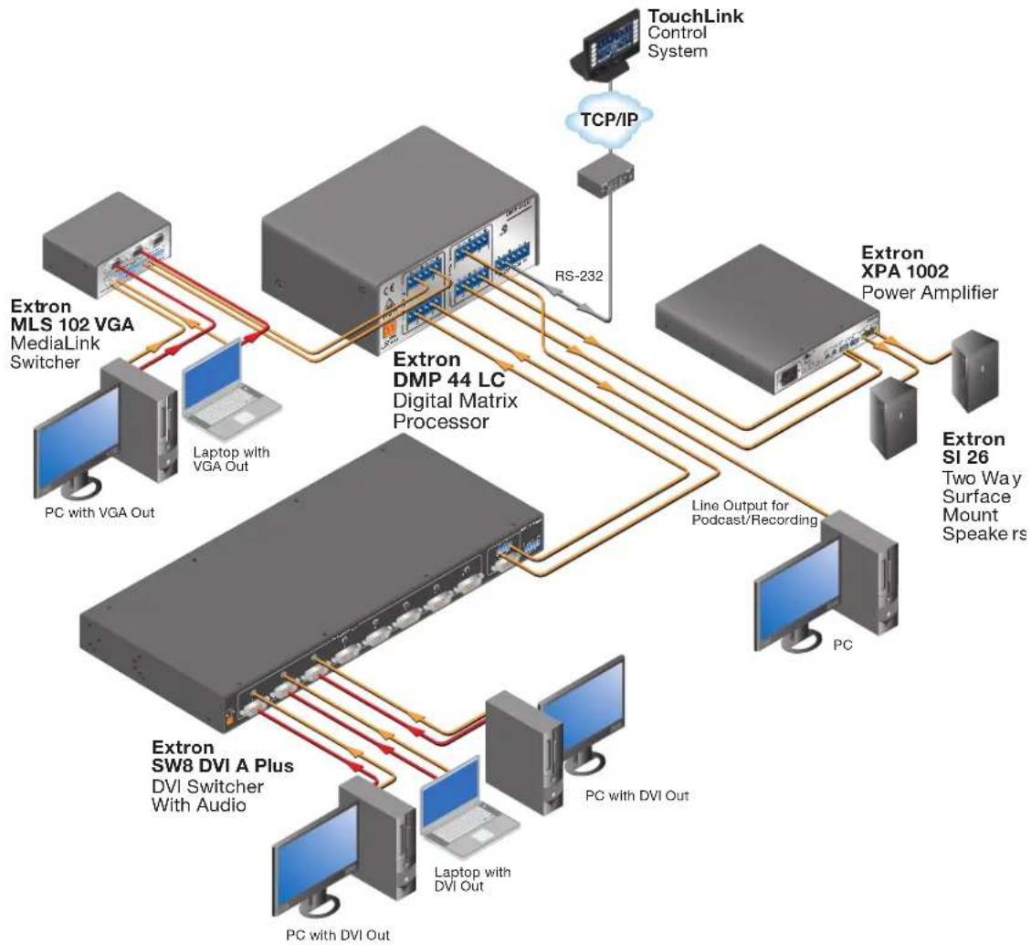
DMP 44 LC Application Diagram
flowchart
graph TD
    A["Extron MLS 102 VGA\nMediaLink Switcher"] -->|PC with VGA Out| B["Extron DMP 44 LC\nDigital Matrix Processor"]
    C["Extron XPA 1002\nPower Amplifier"] -->|Line Output for Podcast/Recording| B
    B -->|RS-232| D["TouchLink Control System"]
    B -->|PC with DVI Out| E["Extron SW8 DVI A Plus\nDVI Switcher With Audio"]
    B -->|PC with DVI Out| F["Laptop with DVI Out"]
    B --> G["Extron SI 26\nTwo Way Surface Mount Speake rs"]
    B --> H["PC with VGA Out"]
    B --> I["Extron XPA 1002\nPower Amplifier"]
    J["PC with VGA Out"] --> K["Laptop with VGA Out"]
    K --> L["Extron MLS 102 VGA\nMediaLink Switcher"]
    M["Extron XPA 1002\nPower Amplifier"] --> N["Extron SI 26\nTwo Way Surface Mount Speake rs"]
Figure 1. Typical Application of the DMP 44 LC
Installation and Operation
This section describes the installation and operation of the DMP 44 LC, including:
• Mounting the DMP 44 LC
• Rear Panel Features and Cabling
- Front Panel Features
- Operations
Mounting the DMP 44 LC
The 1U high, quarter rack width, 3.0 inch deep DMP 44 LC Digital Matrix Processor can be set on a table or mounted on a rack shelf, under a desk or tabletop, or on a projector bracket (see Mounting on page 69 for detailed mounting instructions).
Rear Panel Features and Cabling
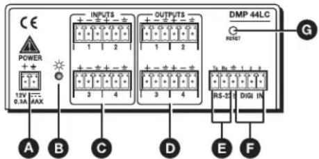
Figure 2. DMP 44 LC Rear Panel
A Power connector
E RS-232 connector
B Power and Reset LED
F Digital input connector
© Line 1-4 input connectors
G Reset button
D Mono output connectors (1-4)
Power connector — Connect the included 12 VDC external power supply into the 2-pole, 3.5 mm captive screw connector. Be careful to observe the correct polarity.
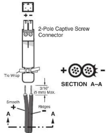
Power Supply Output Cord
Figure 3. Wiring the Power Supply
WARNING: The two power cord wires must be kept separate while the power supply is plugged in. Remove power before wiring.
Use the supplied tie-wrap to strap the power cord to the extended tail of the connector.
NOTE: To avoid losing adjustments when configuring the DMP 44 LC via SIS commands issue a 2FF or if using the DSP Configurator, select
Tools > Save Changes to Device to store the latest changes to the device. Wait several minutes after saving the adjustments before disconnecting power.
B Power and Reset LED — This green LED lights when the DMP 44 LC is operational. It also blinks to indicate the mode of reset that is being accessed (see Resetting on page 9). This LED performs the same functions as the front panel LED (see Front Panel Features and Cabling on page 9).
C Line 1-4 input connectors — 6-pole, 3.5 mm double-stacked captive screw connectors accept balanced or unbalanced mono line level signals. Line inputs provide gain settings to accommodate consumer (-10 dBV) and professional (+4 dBu) operating line level sources. Up to four mono line inputs, balanced and unbalanced in any combination can be connected to these inputs.
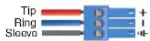
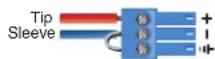
Balanced Input Unbalanced Input
Figure 4. Wiring Balanced or Unbalanced Line Inputs
Mono output connectors (1-4) — 6-pole, 3.5 mm captive screw connectors provide balanced or unbalanced connections for mono line level output signals.
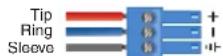
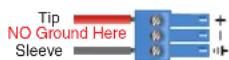
Balanced Input Unbalanced Input
Figure 5. Output Connector Wiring
ATTENTION:
E RS-232 connector — The left three ports of this 6-pole, 3.5 mm captive screw connector provide bidirectional RS-232 (±5 V) serial control. The default baud rate is 38400. This connector shares a common ground with the Digi In (digital input) connector (F).
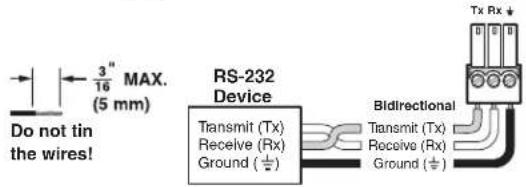

Figure 6. Wiring for RS-232 Communication
You can use the RS-232 and digital input ports simultaneously by connecting a 6-pole captive screw connector with two wires sharing the ground connector (see the illustration at right).
Digital input connector — The Digi In (digital input) port consists of three input pins with the fourth pin being used as a ground (providing three inputs total). It shares a 6-pole, 3.5 mm captive screw connector with the RS-232 port (E) and shares a common ground with it. The digital input connector provides three configurable input ports, allowing connection to various devices including motion detectors, alarms, buttons, photo (light) sensors, and temperature sensors.
The digital input port is used to monitor TTL level digital signals. Voltages greater than 2 V indicate a logic "high" signal while voltages less than 0.8 V indicate a logic "low" signal.
NOTE: These three ports are configured via DSP Configurator (see Configuring the Digital Input Ports on page 39).
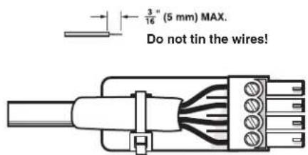
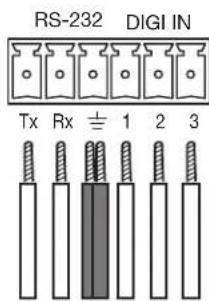
Figure 7. Connecting to the Digital Input Ports
You can use the RS-232 and digital input ports simultaneously by connecting a 6-pole captive screw connector with two wires sharing the ground connector (see the illustration at right).
G Reset button — The recessed reset button is used to access various modes of resets. The single green power LEDs on both the front and rear panels indicate which mode of reset has been accessed (see Resetting on the next page).
Front Panel Features
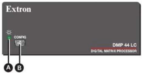
Figure 8. DMP 44 LC Front Panel
Power or Reset LED — This green power indicator lights when the DMP 44 LC is operational. It also blinks to indicate the level of reset being selected (see Resetting).
B Configuration connector — The USB Config port is a mini-B connector to which a host computer can be connected via a USB A male to mini B Male configuration cable. You must install the DMP 44 LC USB driver prior to using the port (see Installing the USB Driver on page 13).
The DMP 44 LC appears as a USB peripheral device with bidirectional communication. The USB connection can be used for software and SIS control and provides an alternative to the rear panel RS-232 port (see RS-232 connector on page 8).
Operations
Powering On and Off
To power the DMP on, plug the provided external 12 VDC, 1 A power supply into the rear panel power connector and into an AC power outlet. Unplug the power supply to power off.
Current mixing and audio processor settings—the current state of the device—are saved in nonvolatile memory. When the unit is powered off, all settings are retained. When the unit is powered back on, it recalls settings from the nonvolatile memory. If a configuration was in process during the power down, these saved mix, audio level, and audio DSP processor settings become active.
On power up, the green power and reset LEDs on the front panel (see figure 8, A) and rear panel (see figure 2, B, on page 5) blink twice, then light steadily when the unit is available for operation or configuration.
Resetting
A recessed actuator button on the rear panel (see figure 2, G, on page 5) initiates two reset modes. The green front panel LED (see figure 8, A) and rear panel LED (see figure 2, B) blink to indicate the reset modes as described in this section.
Resetting the unit causes various settings to revert to factory defaults. There are two reset modes (numbered 1 and 5 for the sake of comparison with Extron IP Link products) that are available by pressing the Reset button. This button is recessed, so you must use a pointed stylus, ballpoint pen, or small screwdriver to press it (see the Reset Modes Summary table on the next page for an explanation of the reset modes).
ATTENTION:
NOTE: Control software cannot function correctly if you use an earlier firmware version.
The default (reset) state of the DMP 44 LC is:
- Inputs 1 to 4 are mixed to corresponding outputs 1 to 4 (all other mix-points are set to 0 dB gain and muted).
- All inputs are active (unmuted, 0 dB gain).
- All outputs are active (unmuted, 100% volume).
- No inserted or active DSP processing remains.
- Group master memory is clear (empty).
- No presets are saved.
• Digital input ports are inactive and not configured.
| DMP 44 LC Reset Mode Summary | ||||
| Mode | Mode Activation Result Purpose | and Notes | ||
| Use Factory Firmware | 1 Hold the reset button while applying power. | The DMP 44 LC reverts to the factory default firmware.Event scripting does not start if the DMP 44 LC is powered on in this mode. All user files and settings (drivers, adjustments, and so on) are maintained. | Mode 1 reverts to the factory default firmware version if incompatibility issues arise with user- loaded firmware. | |
| Reset to Factory Defaults | 5 Press and hold the Reset button for about 9 seconds until the Power LED blinks three times (once at 3 seconds, again at 6 seconds, and again at 9 seconds), then release and, within 1 second, press Reset momentarily (<1 second). | NOTE: After a mode 1 reset, update the DMP 44 LC firmware to the latest version. Do not operate using the firmware version that results from a reset in this mode. | Mode 5 performs a complete reset to factory defaults, except for firmware:Sets port mapping to the factory default.Turns DHCP off.Turn events off.Mutes all mix-points and sets them to 0 dB.Unmutes all inputs and outputs and sets them to 0 dB.Returns DSP processing to defaults and bypassed.Clears all presets and group master memory. | |
Software Configuration
The DSP Configurator software program provides the means to configure the DMP 44 LC so that it can function with no or minimal operator intervention. The DSP Configurator is available on the Extron website and can be installed on a PC running Windows® XP® or newer.
This section provides instructions for obtaining, installing, and using the software to configure the DMP 44 LC. Topics include:
• About the DSP Configurator
- Downloading and Installing the DSP Configurator Program
- Operating Modes
- Configuring the DMP 44 LC
- Presets
- Pulling or Pushing a Configuration and Switching to Live Mode
Certain functions of the DMP 44 LC can also be configured via Extron Simple Instruction Set (SIS) commands using a terminal emulation program such as Extron DataViewer (also available from www.extron.com). See SIS Programming and Control, beginning on page 56, for information on this type of communication.
About the DSP Configurator
The DSP Configurator is a Windows-based control program that is compatible with Windows® 2000, Windows XP, Windows 7, and later versions. It provides remote configuration and control of all DMP features and functions. This program controls the DMP through either a front panel USB connection or a rear panel RS-232 connection.
Defaults
By default, the DMP 44 LC is configured for immediate operation with each input routed to its respective output (Input 1 routed to output 1, input 2 routed to output 2, and so on). While these settings allow the device to pass audio when first connected, it rarely meets the needs of most applications. The DSP Configurator software enables you to fully configure the DMP 44 LC for your own applications. The DSP Configurator software initially opens with a blank configuration with no processing and no mixing or routing. All gain stages are set to “unity,” or 0 dB of gain.
Gain Control
Input and output gain stages provide metering in dBFS that assists you in configuring the device for optimal operation. Because the DMP 44 LC is a digital device, optimal operating levels remain close to 0 dBFS (0 dB “full scale” on the input or output meters) without ever exceeding that level. Levels above 0 dBFS cause clipping, which is always audible on a digital device.
All gain stages in the DMP are mono. Gain can also be controlled using a group master, which is configured with the DSP Configurator software. Group masters can be used to group multiple gain or mute controls, group multiple bass or treble boost and cut controls, gang two gain or mute controls for stereo operation, or even to control a single gain point. Soft limits can be applied to group masters. Sometimes a particular gain range can be too great, allowing for settings that are too loud or too soft, while in some instances the loudest settings can cause feedback or clipping. Soft limits can be used to limit the gain range for smoother operation.
Processing Tools
Finally, the DMP 44 LC provides a comprehensive set of DSP processing tools. The filter tools are available to shape the tonal quality of your source material or to equalize the room to compensate for acoustic gain. The dynamics processors are available for level control or system protection.
Downloading and Installing the DSP Configurator Program
The DSP Configurator is available on www.extron.com. From this site, you can also download updates to the software as they become available. To access the software:
- Open the Extron web page and select the Download tab.
- On the Download screen, click the Software button (shown at right).
The Download Center – Software screen appears, containing a list of control software products.
- In one of the linked alphabets at the top and bottom of the screen, click D.
- On the D software products page, scroll to locate the DSP Configurator, and click the Download link at the far right (see figure 9, 1).
| DSP Configurator | 79-530-01 | 2.5 | Aug. 15, 2013 | 51.2 MB | Download |
| The DSP Configurator™ Software is the user interface to ProDSP™ for full control and management of a ProDSP-capable product. | |||||
| Learn More Release Notes | |||||
Figure 9. DSP Configurator Link on the Extron Website
- On the next screen, fill in the required information.
-
Click the Download dsp_configurator_vnxn.exe button. Depending on your browser and Windows version, one of the following appears:
-
A File Download - Security Warning window opens. On this window, click Run. When a second File Download - Security Warning window opens, click Run on it to start the firmware installation wizard.
- A button containing the name of the firmware file appears at the bottom of the browser screen. Click this button to display an Open File - Security Warning window. Click Run on this window to start the software installation wizard.
- A confirmation window appears at the bottom of the browser screen. Click Run on this prompt to start the installation wizard.
NOTE: If you want to save the installation file to your computer hard drive to run later, click Save. On the Save As window that opens, save the setup file to the desired location. When you are ready to install the software, double-click on the Download dsp_configurator_vnxn.exe icon, click Run on the download screen that opens, and restart this procedure at step 7.
- Follow the instructions on the InstallShield Wizard screens to complete the software program installation. By default the installation creates a folder called DSP_Configurator in one of the following locations on the computer:
c:\Program Files (x86)\Extron\DSP_Configurator [for Windows 7 and later] c:\Program Files\Extron\DSP_Configurator [for Windows XP and earlier] If there is not already an Extron folder in your program files folder, the installation program creates it as well.
Installing the USB Driver
When the DSP Configurator installation is complete, the USB installer starts automatically. It is recommended to install the USB driver whether it will be used immediately or not. To install the USB driver:
- After the DSP Configurator program installation is complete, click Next to proceed. The USB driver installer launches and searches for the driver on the network.
- When the installer has completed the downloading and installation of the USB driver, click Finish to complete the driver installation and close the installer.
Starting the Program
- To start the DSP Configurator program, on your desktop click Start > All Programs > Extron Electronics > DSP Configurator > DSP Configurator.
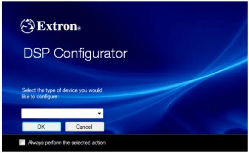
Figure 10. Opening Screen of DSP Configurator
The DSP Configurator program opens in Emulate mode (see Operating Modes on page 15).
- From the drop-down menu, select DMP 44 LC, then click OK.
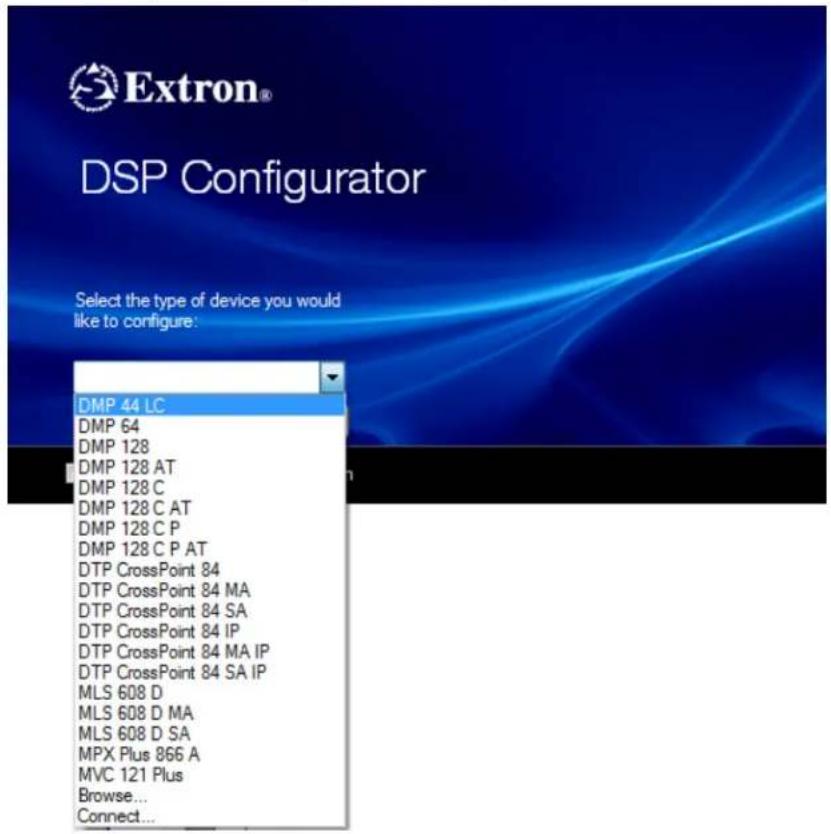
Figure 11. Device Drop-down Menu
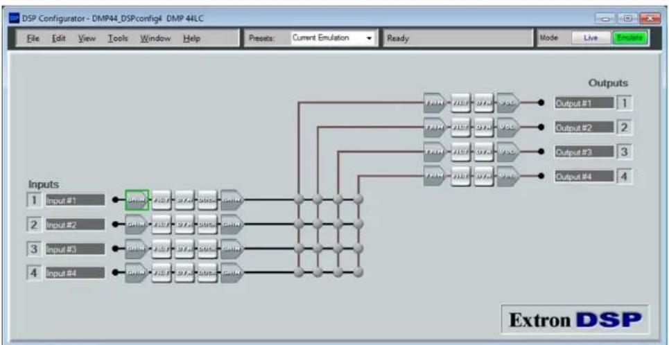
The DSP Configurator main screen is displayed.
flowchart
graph TD
    A["Input 1: Input #1"] --> B["GRN"]
    C["Input 2: Input #2"] --> D["GRN"]
    E["Input 3: Input #3"] --> F["GRN"]
    G["Input 4: Input #4"] --> H["GRN"]
    B --> I["FLTR"]
    D --> J["FLTR"]
    F --> K["FLTR"]
    H --> L["FLTR"]
    I --> M["FLTR"]
    J --> N["FLTR"]
    K --> O["FLTR"]
    L --> P["FLTR"]
    M --> Q["FLTR"]
    N --> R["FLTR"]
    O --> S["FLTR"]
    P --> T["FLTR"]
    Q --> U["FLTR"]
    R --> V["FLTR"]
    S --> W["FLTR"]
    T --> X["FLTR"]
    U --> Y["FLTR"]
    V --> Z["FLTR"]
    W --> AA["FLTR"]
    X --> AB["FLTR"]
    Y --> AC["FLTR"]
    Z --> AD["Output #1"]
    AA --> AE["Output #2"]
    AB --> AF["Output #3"]
    AC --> AG["Output #4"]
Figure 12. DSP Configurator Audio I/O Workspace (Main Screen)
Operating Modes
The DSP Configurator program has two operational modes: emulate and live.
- In Emulate mode, the DMP is not connected to the host running DSP Configurator. The program provides access to all functions of the DMP 44 LC so that you can work offline to create or edit configurations. Configurations created in emulate mode do not affect DMP 44 LC operation until they are uploaded to the device.
- In Live mode, the program has established a connection and is synced with the DMP 44 LC. Changes affect the DMP in real-time, and changes in the current state of the DMP are reflected in DSP Configurator.
The DSP Configurator program always opens in emulate mode, indicated by green highlighting of Emulate button in the Mode section of the menu bar (see figure 13).

Figure 13. Menu Bar at Startup in Emulate Mode
In emulate mode, you can build a new configuration from the default screen or open an existing file that contains a previously saved configuration. Settings and adjustments are saved to a configuration file at a selected location on the PC. When a previously saved file is opened in emulate mode, it becomes the current emulation displayed in the Presets field.
A new or previous file cannot be opened in live mode. You can select audio parameters in emulate mode, then transfer them to the connected DMP 44 LC after switching to live mode. You can also tailor audio settings in live mode, allowing real-time auditioning of the audio output as adjustments are made.
It is recommended that you create your configuration in emulate mode, then switch to live mode when ready to upload it to the DMP (see Pulling and Pushing a Configuration and Switching to Live Mode on page 49). However, you can switch to live mode at any time after opening the program with a blank configuration, after creating a configuration, or after loading a previously saved configuration file.
Configuring the DMP 44 LC
This section contains descriptions of the controls on the DSP Configurator Audio I/O workspace (the main screen, displayed when the DSP Configurator opens) and procedures for configuring the audio input and output and digital input ports of the DMP. For additional detailed procedures, see the DSP Configurator help file, accessed by selecting Contents from the Help menu on the main screen.
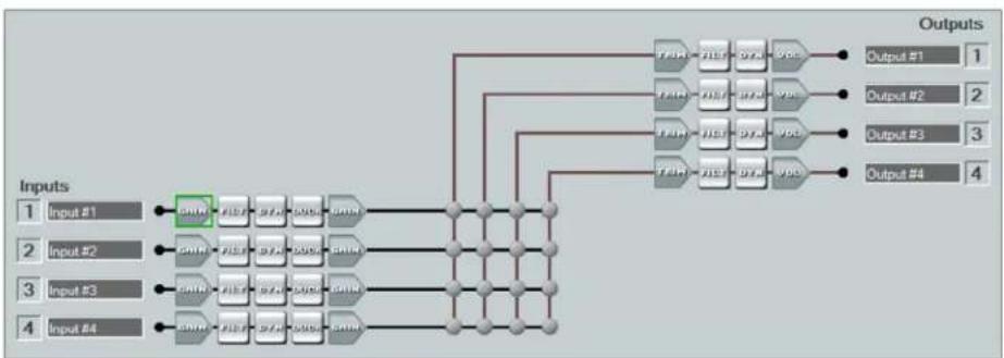
By default, the Audio I/O workspace is displayed when the DSP Configurator is opened. The diagram on this workspace (see figure 14) shows the signal flow and DSP processing per signal chain. The following sections describe the signal processing, parameter ranges, and procedures for configuring and mixing inputs and outputs using the DSP Configurator.
flowchart
graph TD
    A["Input #1"] --> B["CHN"]
    C["Input #2"] --> D["CHN"]
    E["Input #3"] --> F["CHN"]
    G["Input #4"] --> H["CHN"]
    B --> I["Channel"]
    D --> J["Channel"]
    F --> K["Channel"]
    H --> L["Channel"]
    I --> M["Output #1"]
    J --> N["Output #2"]
    K --> O["Output #3"]
    L --> P["Output #4"]
    M --> Q["Outputs"]
    N --> Q
    O --> Q
    P --> Q
Figure 14. Signal Flow Diagram on DSP Configurator Audio I/O Workspace
Processor Blocks
Processor blocks can be placed in the input and output signal chains, shown in the Audio I/O workspace diagram, to perform specific tasks. There are level control blocks, signal processor blocks, and mix-point matrix blocks (with level control). Level control processors are always active and do not have to be inserted. The following sections provide details of navigation, menus, and other interface operations. The processor blocks, while performing different functions, have several common elements.
- Insert — All blocks (except level controls) can be inserted by right-clicking on the appropriate box in the signal chain and selecting the desired block from the drop-down context menu. For example, in figure 15 a High Pass filter block has been added to the Filt (filter) box in the input signal chain.
- Remove a processor — To remove an active processors, right-click on the block and select Delete or select the block and press
on the keyboard. This sets the parameters back to default and removes (deactivates) the block.
To replace an active processor, right-click it and insert a new one. A prompt appears to indicate the previous processor is about to be replaced.
- Mute — When a level block (gain, trim, or volume) is muted, all signal flow is blocked. When mute is active, a red mark appears in the lower-left corner of the block. Mix-point mute is indicated by shadowing the mix-point.
- Bypass — When bypass is active, signal flow passes through the block without processing, regardless of the settings. When bypass is removed, the signal is processed according to the parameter settings. A red mark appears in the lower-left corner of the block (shown in figure 15) to indicate that it has been inserted, but is currently bypassed.

Figure 15. Bypass Indicator on a High Pass Block
Line Input Signal Chain
There are four mono line input channels. The channel controls and processing blocks described in this section are identical for each of the four inputs.

flowchart
graph LR
    A["Inputs 1 Input #1"] --> B["GAIN"]
    B --> C["FILT"]
    C --> D["DYN"]
    D --> E["DUCK"]
    E --> F["GAIN"]
Figure 16. Line Input Channel Controls
Input signal chain elements from left to right include:
- Line input gain (GAIN) — Mono gain control with a range from -18 to +24 dB includes a mute button and is adjustable in increments of 0.1 dB. A Polarity button (click to toggle between + and -) is provided. Gain and mute controls are provided pre-meter (see Line input gain block on the next page for more information).
- Filter (FILT) — Up to three filters can be inserted for an input, in any combination of High Pass, Low Pass, Bass, Treble, or Parametric Equalizer. After a filter is inserted, you can select a new type for it from its drop-down menu on the Filter dialog box if desired (see Filter block — input on page 23 for more information).
- Dynamics (DYN) — One compressor per block, per channel. Dynamics processors vary the dynamic level, or the range of loudest to softest signals (see Dynamics processor block—input on page 29 for more information).
- Ducking (DUCK) — One ducker per block, per channel. Three levels of priority are available, at which a ducker can function as both a source and a target (as an example one source can be ducked by another source, and also trigger ducking on program channels). See Ducking block on page 31 for more information.
- Pre-mixer gain (GAIN) — One pre-mixer gain control per channel with a range of -100 dB to +6 dB, adjustable in increments of 0.1 dB. This control can be used to control program level independent of microphone mixer levels. It can also be used to compensate for any level changes due to processing (see Pre-mixer Gain block on page 34 for more information).
Line Input Gain block
Line inputs have gain settings to accommodate consumer and professional line level sources. The line input channel Gain block provides a mono long-throw fader for gain and attenuation. The range for the control is -18 to +24 dB, in steps of 0.1 dB. The default is unmuted at unity gain (0.0 dB).
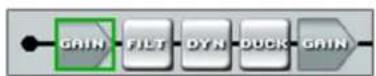
Figure 17. Line Input Gain Box
To make gain adjustments:
- To display the gain controls, double-click the desired input Gain block. The Line Input Gain dialog box opens.
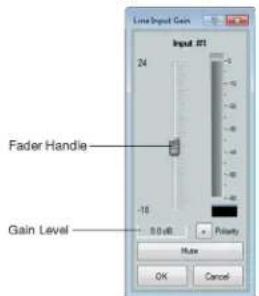
Figure 18. Line Input Gain Level Controls
-
Click the fader handle or within the fader area to bring focus to the fader.
-
To adjust the input signal level, do any of the following:
-
Click and hold the fader handle, then drag it to the desired level in 0.1 dB steps (direct adjustment).
- Click or tab to the fader handle, then
or to the desired level in 1 dB steps. Press the or key to increase or decrease the level in 10 dB steps. -
Click in or tab to the signal level readout field. Type a new value, then press
or to another area. -
Click OK to confirm the settings or Cancel to close the dialog box without making the changes.
Configuring Gain and Mute groups
To configure gain and mute groups:
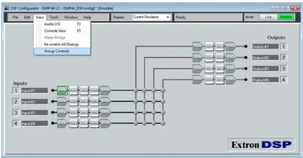
- On the menu bar, click View > Group Controls.
flowchart
graph TD
    A["Input #1"] --> B["Group Controls"]
    C["Input #2"] --> B
    D["Input #3"] --> B
    E["Input #4"] --> B
    B --> F["Outputs"]
    F --> G["Output #1 1"]
    F --> H["Output #2 2"]
    F --> I["Output #3 3"]
    F --> J["Output #4 4"]
Figure 19. Selecting Group Controls
- To add a new group, select Add a Group.
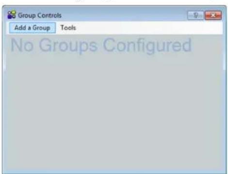
Figure 20. Adding a New Group
- Select a group to configure.
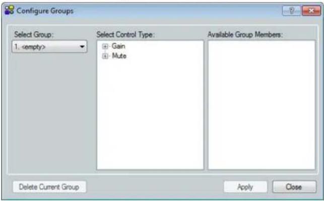
Figure 21. Selecting a Group
NOTE: To configure bass and treble groups, see Configuring Bass and Treble groups on the next page.
- Select the gain or mute control type for the group.
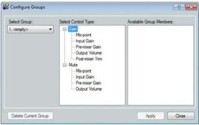
Figure 22. Selecting the Group Control Type (Gain or Mute)
- Define the group members.
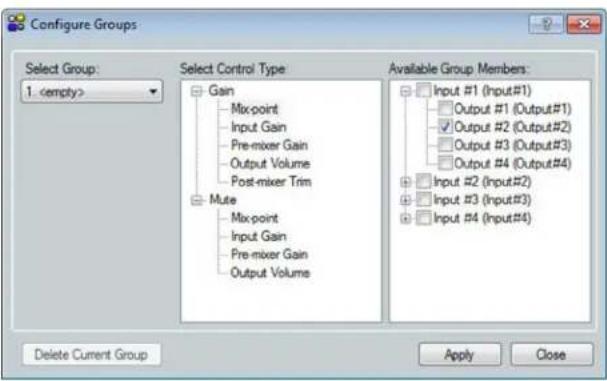
Figure 23. Selecting Members of the Gain or Mute Control Group
Configuring Bass and Treble groups
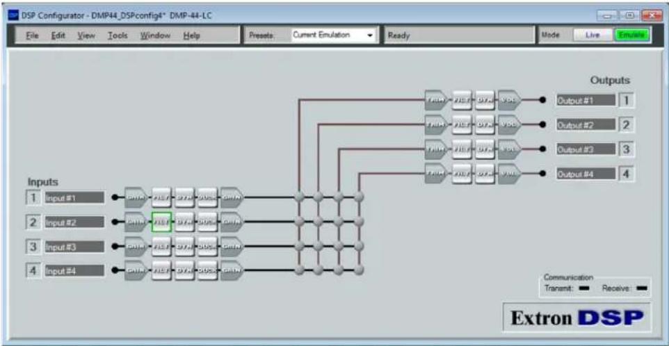
- On the main DSP Configurator screen, right-click the input Filt block.
flowchart
graph TD
    A["Input #1"] --> B["SNP"]
    A --> C["AES"]
    A --> D["D7A"]
    A --> E["DSBSC"]
    A --> F["GNAT"]
    G["Input #2"] --> H["GNP"]
    G --> I["AES"]
    G --> J["D7A"]
    G --> K["DSBSC"]
    G --> L["GNAT"]
    M["Input #3"] --> N["SNP"]
    M --> O["AES"]
    M --> P["D7A"]
    M --> Q["DSBSC"]
    M --> R["GNAT"]
    S["Input #4"] --> T["GNP"]
    S --> U["AES"]
    S --> V["D7A"]
    S --> W["DSBSC"]
    S --> X["GNAT"]
    Y["Inputs"] --> Z["Outputs"]
    Z --> AA["Output #1"]
    Z --> AB["Output #2"]
    Z --> AC["Output #3"]
    Z --> AD["Output #4"]
    Z --> AE["Communications: Transent: Receive: Extron DSP"]
Figure 24. Filters Box Selected for an Input on the Audio I/O Workspace
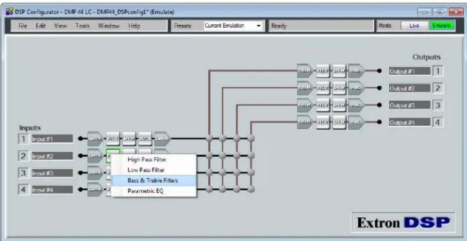
- From the filters drop-down menu, select Bass & Treble Filters. The Filt block name changes to Bass - Treb.
flowchart
graph TD
    A["Input #1"] --> B["High Pass Filter"]
    C["Input #2"] --> D["Low Pass Filter"]
    E["Input #3"] --> F["Bass & Trable Filters"]
    G["Input #4"] --> H["Parametric EQ"]
    B --> I["Outputs"]
    D --> I
    F --> I
    H --> I
    I --> J["Output #1 1"]
    I --> K["Output #2 2"]
    I --> L["Output #3 3"]
    I --> M["Output #4 4"]
Figure 25. Selecting Bass & Treble Filters from Filters Drop-down Menu
- Double-click the Bass-Treb processor block to open the Filter dialog box.
NOTE: The Bypass button is red when a filter is bypassed or not active. Deselect it to configure the filter.
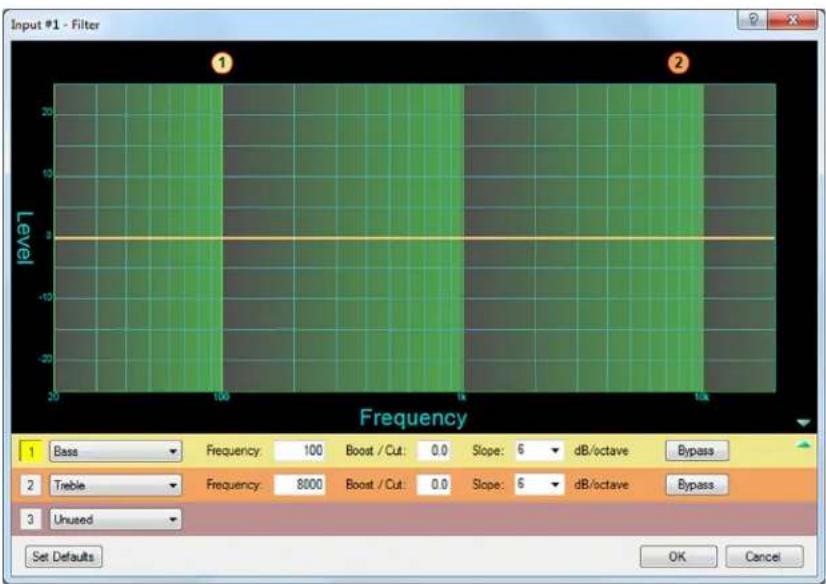
Figure 26. Filter Dialog Box
- Configure the bass and treble parameters as desired.
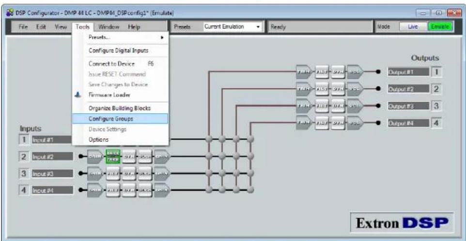
- On the menu bar, select Tools < Control Groups.
flowchart
graph TD
    A["Input #1"] --> B["Configure Groups"]
    C["Input #2"] --> B
    D["Input #3"] --> B
    E["Input #4"] --> B
    B --> F["Device Settings"]
    F --> G["Options"]
    G --> H["Output #1"]
    H --> I["Extron DSP"]
    style A fill:#f9f,stroke:#333
    style C fill:#f9f,stroke:#333
    style D fill:#f9f,stroke:#333
    style E fill:#f9f,stroke:#333
Figure 27. Control Groups Option on the Tools Menu
- In the Configure Groups dialog box, select the Bass or Treble control group (1).
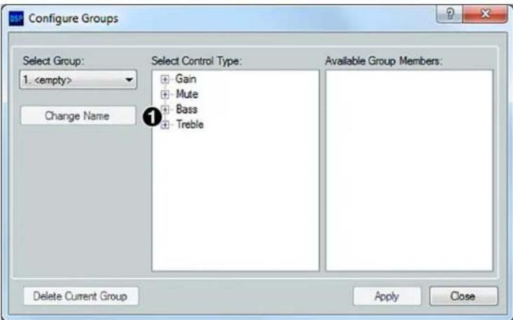
Figure 28. Selecting the Control Group (Bass or Treble)
- Select the Bass or Treble group (①) and its members (②).
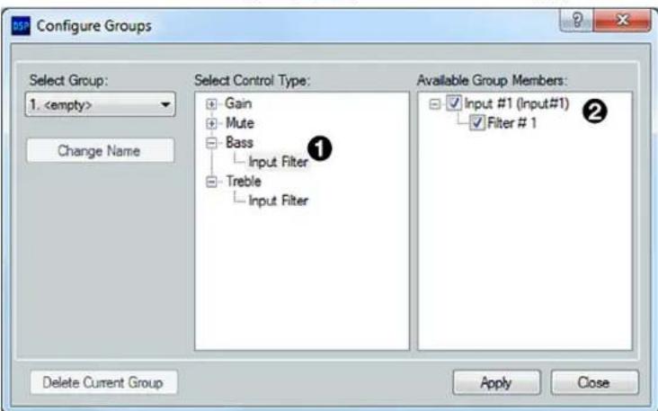
Figure 29. Selecting Members of the Bass or Treble Control Group
- Repeat steps 6 and 7 for the remaining control group (Bass or Treble).
Filter block - input
Each line input channel filter block allows a total of five filters. To insert a filter:
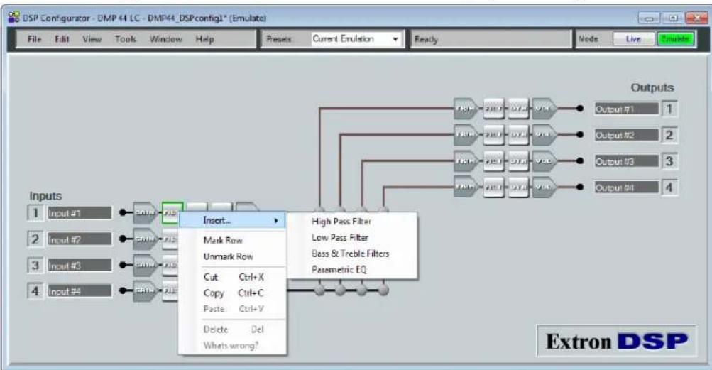
- Right-click the desired Filt block to display the filter context menu.
Alternatively, you can double-click the Filt block to display the filter type submenu.
flowchart
graph TD
    A["Input #1"] --> B["EBIN"]
    C["Input #2"] --> D["EBIN"]
    E["Input #3"] --> F["EBIN"]
    G["Input #4"] --> H["EBIN"]
    B --> I["Insert..."]
    D --> I
    F --> I
    H --> I
    I --> J["Mark Row"]
    I --> K["Unmark Row"]
    J --> L["Cut Ctrl+X"]
    J --> M["Copy Ctrl+C"]
    J --> N["Paste Ctrl+V"]
    J --> O["Delete Del"]
    J --> P["Whats wrong?"]
    L --> Q["High Pass Filter"]
    M --> Q
    N --> Q
    O --> Q
    P --> Q
    Q --> R["Low Pass Filter"]
    Q --> S["Bass & Treble Filters"]
    Q --> T["Parametric EQ"]
    R --> U["Output #1"]
    S --> V["Output #2"]
    T --> W["Output #3"]
    U --> X["Outputs"]
    V --> Y["Outputs"]
    W --> Z["Outputs"]
Figure 30. Selecting a Filter to Insert
- Select Insert, then select the desired filter type from the drop-down submenu. The filter type replaces Filt in the block.

Figure 31. Filter Block Added to Input 2
- Double-click the new filter block to open the filter setup dialog box.
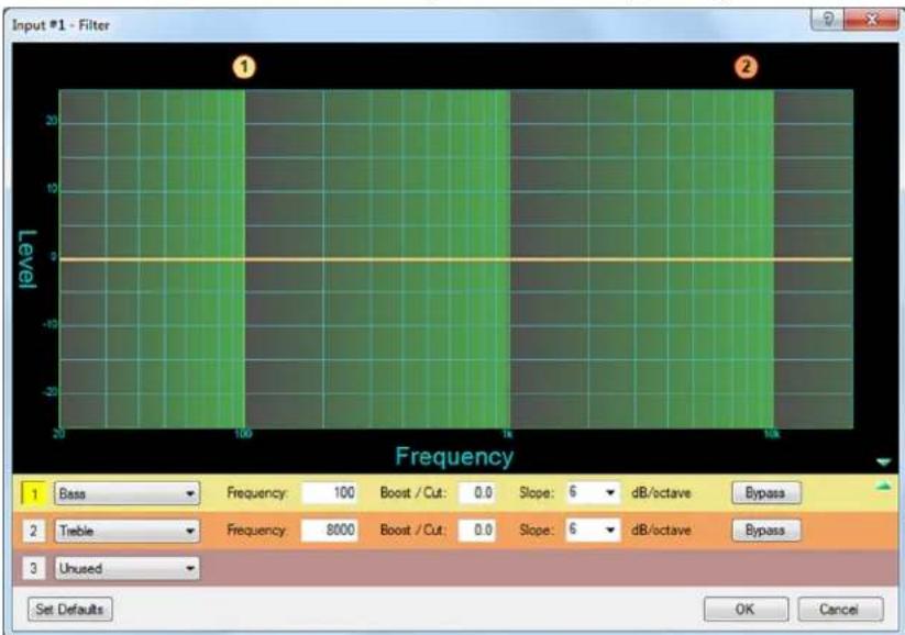
Figure 32. Filter Block Dialog Box
- On the filter dialog box, modify the filter parameters as desired. Each filter loads with all applicable default parameters displayed to the right of each filter drop-down menu.
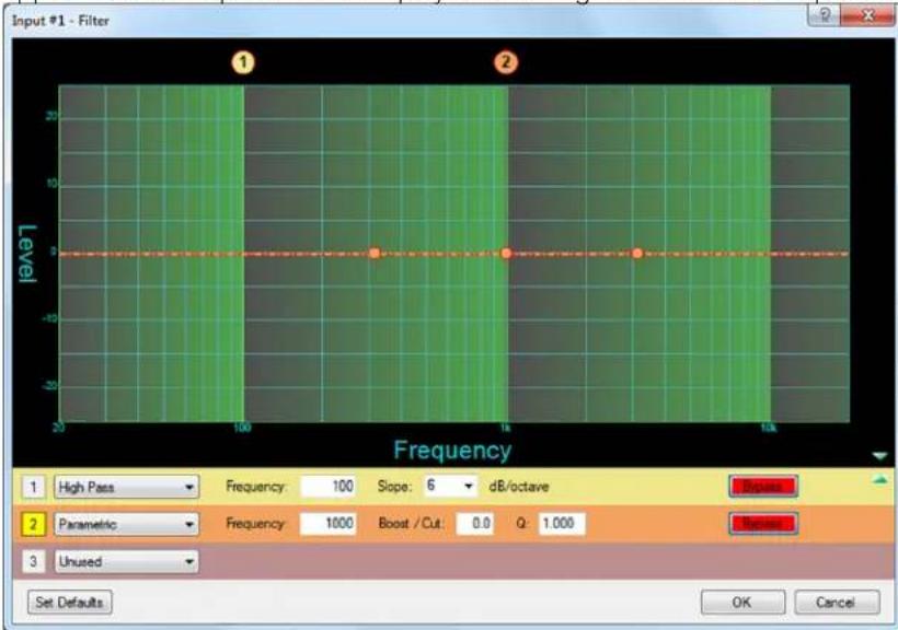
Figure 33. Filter Dialog Box with Filters Added
- Within the dialog box, a filter is focused (selected) when a filter type is inserted, or when its number in the box to the left of the filter drop-down menu is clicked.
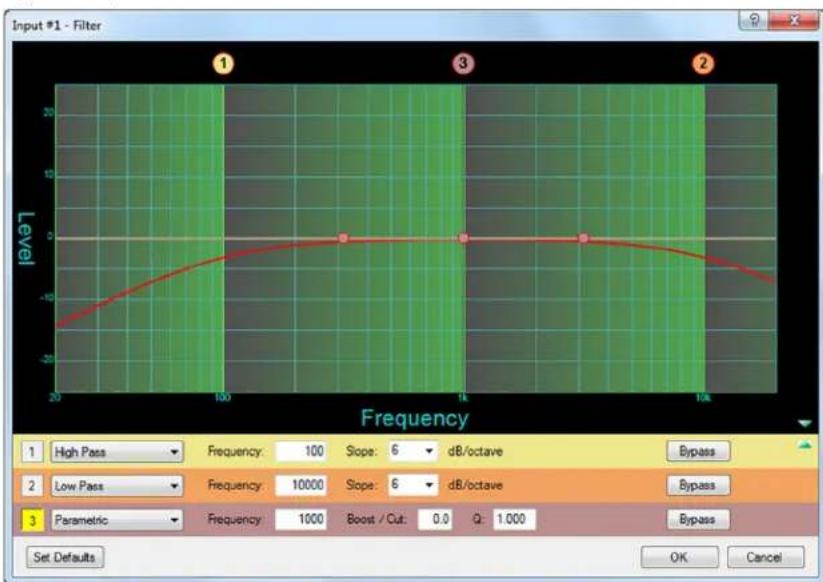
In the example in figure 34, the box for filter 3 is highlighted in yellow, indicating that it is the filter in focus. When a bypassed filter is focused (independent of other filters), it is represented in the graph as a dotted line of the same color as its filter row (and the Bypass button in its row is red). When the filter is active (not bypassed), the line is solid.
line
| Frequency | Level | | --------- | ----- | | 100 | -20 | | 1k | 0 | | 10k | -20 |Figure 34. Filter Dialog Box, Filter Not Bypassed
- When multiple filters are enabled, the graph indicates the focused filter result (independent of other filters) in the color of the filter row background in the type or parameters table. The composite response of all filters is displayed in red.
- Above the graph, each filter has a handle that is placed directly above the cutoff or center frequency whose number corresponds to the filter number (outlined in red). Clicking a handle or clicking the table row brings focus to that filter and its handle becomes red. Click and drag the handle horizontally to change the cutoff or center frequency to a new position on the x axis.
- If desired, add more filters as follows:
a. In the filter table at the bottom of the screen, select a filter type from the drop-down menu of the desired filter (see the example in figure 35).
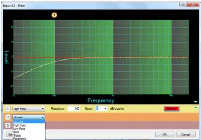
Figure 35. Selecting a Filter Type from the Filter 2 Drop-down Menu
b. Make any desired modifications to the new filter.
Parametric (equalizer) filters
Up to three parametric filters can be placed in the filter box at one time. Each can be set to a different frequency, creating a three-band parametric equalizer. The control boosts or cuts the center frequency. Also, by changing the Q value, you can widen or narrow the range of affected frequencies around the center frequency. In general, the higher the Q value, the narrower the affected bandwidth is.
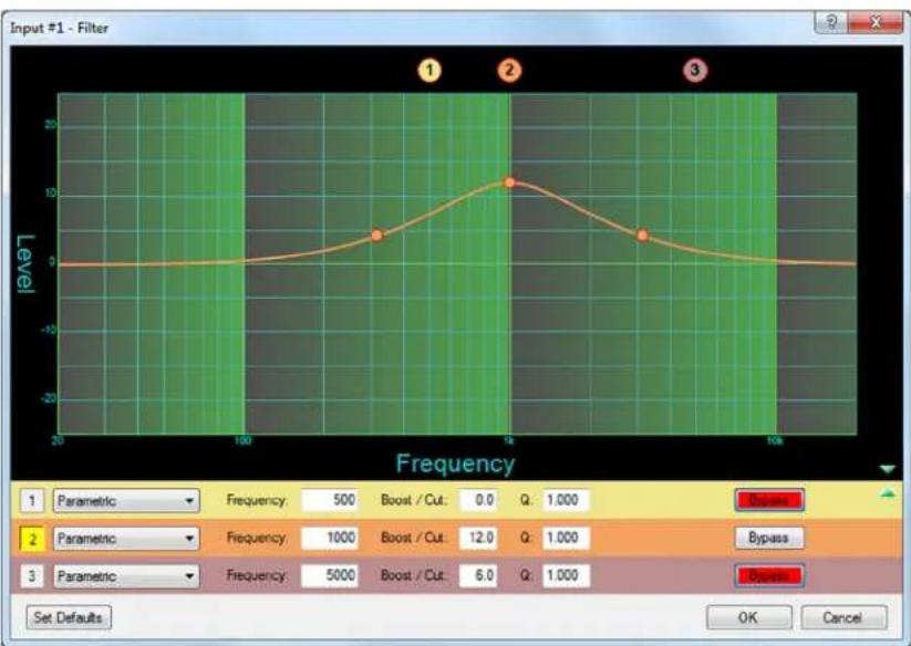
To demonstrate how Q affects the filter, see the filter dialog box in figure 36 on the next page, which contains three parametric filters centered at different frequencies but with the same Q value of 1.0. The filter that is in focus (2) has a center frequency of 1000 Hz, boosting that frequency +12 dB over a Q of 1.0. Note that the markers on either side of the peak frequency are at 200 Hz on the left and 5000 Hz on the right, a bandwidth of about 4800 Hz.
line
| Frequency | Level | | --------- | ----- | | 100 | 4 | | 150 | 12 |Figure 36. Parametric Filter Dialog Box, 1000 Hz
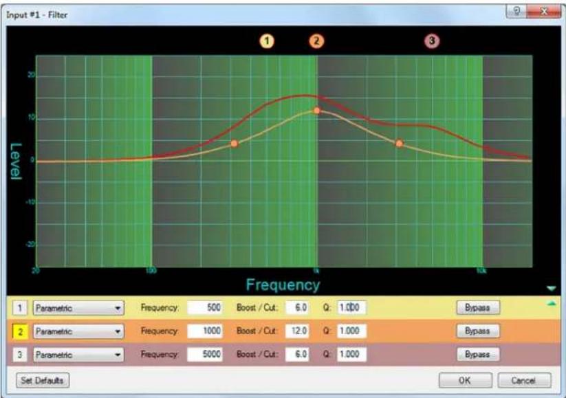
The dialog box in the figure 36 example shows the frequency curve for a single active filter. To add its effect to the overall frequency response, deselect the Bypass button for the other filters, as shown in the figure 37.
line
| Frequency | Level | | --------- | ----- | | Peak 1 | 12.0 | | Peak 2 | 10.0 | | Peak 3 | 5.0 |Figure 37. All Parametric Filters Active
The overall frequency response is now shown in figure 37 as a solid red line with the filter in focus, located in row 2 and shown in the color of its table row.
The parametric filter allows frequency selection accurate to 0.1 Hz and either 6 or 12 dB of slope. Note that, at the specified frequency (100 Hz), the signal is 3 dB down, which is typical operation for high pass filters. The 3 dB down point remains constant regardless of the slope setting. Only the steepness of the frequency attenuation curve changes.
High Pass filter
The high pass filter causes all frequencies below the specified frequency to be attenuated, allowing higher frequencies to pass.
In figure 38, the frequencies lower than the specified frequency of 1kHz are attenuated, leaving the higher frequency response flat.
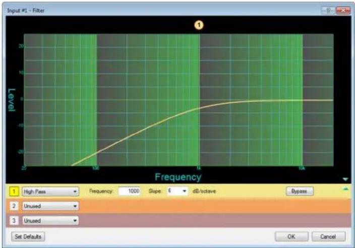
line
| Frequency | Level | | --------- | ----- | | 25 | -20 | | 100 | -10 | | 1A | 0 | | 10A | 8 |Figure 38. High Pass Filter Response Curve
Low Pass filter
The low pass filter is the opposite of the High Pass filter. It causes all frequencies above the specified frequency to be attenuated, allowing lower frequencies to pass. In figure 39, the frequencies higher than the specified frequency of 10 kHz are attenuated, leaving the lower frequency response flat.
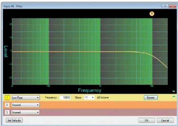
Figure 39. Low Pass Filter Response Curve
Bass and treble tone filters
A tone filter, also known as a shelving filter, gives the ability to cut or boost gain evenly above or below a given frequency. The end-band shape gives the visual appearance of a shelf. Tone filters are generally applied to program material and are expressed as bass and treble control.
To set bass and treble filtering:
- Right-click on the Filt block and select Insert > Bass & Treble Filters on the menu bar. The Filt block changes to Bass - Treb.

flowchart
graph LR
    A["Input #1"] --> B["GAIN"]
    B --> C["BASS TREB"]
    C --> D["DYN"]
    D --> E["DOCK"]
    E --> F["GAIN"]
Figure 40. Bass and Treble Filters Inserted
- Double-click the Bass Treble block to open the Filter dialog box.
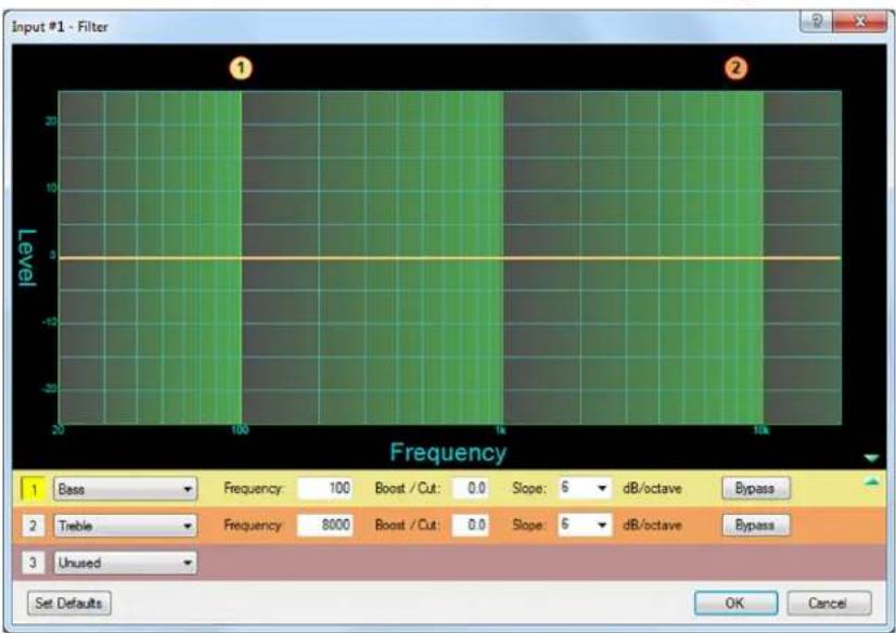
Figure 41. Bass and Treble Filters Selected on the Filter Dialog Box
NOTE: Adding this filter inserts both bass and treble controls in the dialog box. If only a bass or only a treble filter is required, either click Bypass for the unneeded control or select unused from its drop-down menu.
-
Click in the box in front of the bass or treble filter that you want to adjust.
-
Enter or select the desired values Frequency, Boost, and Slope values (see the DSP Configurator help file for the details on the parameters and procedure). The following ranges can be entered or selected:
• Frequency of the controls can be selected to 0.1 Hz accuracy.
- Slopes of 6 and 12 dB/octave are available.
• You can boost or cut the signal up to 24 dB.
Dynamics Processor block - input
A dynamics processor alters the dynamic range, which is the difference between the loudest to the quietest portions of an audio signal. Each input channel has available one dynamics processor block that, when inserted, provides a compressor.
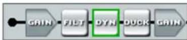
Figure 42. Input Dynamics Processor Box
Compressor
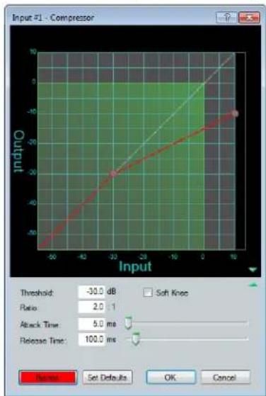
The compressor regulates the signal level by reducing the dynamic range of the input signal above a specified threshold. The input level to output level ratio determines the reduction in the dynamic range beyond the threshold setting. For example, in figure 42, with a ratio setting of 2:1, for every 2 dB of input above the threshold the compressor outputs 1 dB.
Compression is commonly used to contain mic levels within an acceptable range for maximum vocal clarity. A compressor can also make softer sounds louder in one of two ways. The dynamic range can be reduced by compressing the signal above the threshold while raising the post-compressor gain or trim (referred to as “make-up gain”). Alternately, the input signal can be increased while the compression ratio above the threshold is increased correspondingly to prevent clipping. Both techniques have the effect of making louder portions of a signal softer while at the same time increasing softer signals to raise them further above the noise floor.
Compression can also be used to protect a system or a signal chain from overload similar to a limiter.
To insert a dynamics processor into an empty block:
-
Right-click on the Dyn block for the desired input.
-
From the drop-down menu select Insert Compressor > Compressor.
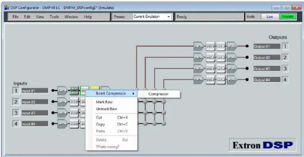
flowchart
graph TD
    A["Input #1"] --> B["Compressor"]
    C["Input #2"] --> D["Insert Compressor"]
    E["Input #3"] --> F["Insert Compressor"]
    G["Input #4"] --> H["Insert Compressor"]
    B --> I["Mark Row"]
    D --> J["Unmark Row"]
    F --> K["Cut Ctrl=X"]
    F --> L["Copy Ctrl+C"]
    F --> M["Paste Ctrl-V"]
    F --> N["Delete Dol"]
    F --> O["Whats wrong?"]
    H --> P["Outputs"]
    I --> Q["Outputs #1 1"]
    J --> R["Outputs #2 2"]
    K --> S["Outputs #3 3"]
    L --> T["Outputs #4 4"]
Figure 43. Selecting Compressor from the Dyn Drop-down Menu
The Dyn box changes to CMP (see figure 44).

flowchart
graph LR
    A["Inputs 1 Input #1"] --> B["GAIN"]
    B --> C["HIGH PASS"]
    C --> D["CHP"]
    D --> E["DUCK"]
    E --> F["GAIN"]
Figure 44. Compressor Block for Input 1
- Double-click the CMP block to open the Compressor dialog box.
NOTE: As an alternative to steps 1 through 3, you can double-click on the Dyn block, then select Compressor from the single-option pop-up menu to open this dialog box.
-
In the Compressor dialog box, enter or adjust the desired parameters. The following parameters are available:
-
Threshold — The input signal level above which compression begins (subject to attack time) and below which compression stops (subject to hold and release time). Threshold level can be adjusted from -80.0 to 0.0 dB in 0.1 dB increments. Default is -30.0 dB.
- Ratio — The input signal level reduction when compression is engaged. The ratio can be adjusted from 1.0 to 100.0 in 0.1 increments. The default is 2.0:1.
- Attack Time — Adjusts the time delay for compression to engage after the input signal level reaches or exceeds the threshold level. Attack time can be adjusted from 0.0 to 200.0 ms in 0.1 ms increments. The default is 5.0 ms.
- Release Time — Adjusts the time it takes to return the signal to normal (unprocessed) levels after the signal no longer exceeds the threshold level setting. Release time begins only after hold time is reached. Release time can be adjusted from 10 to 1000.0 ms in 0.1 ms increments. The default is 100.0 ms.
- Soft Knee — Click the Soft Knee check box to smooth and soften the transition from uncompressed to compressed output levels. There are no adjustments.
line
| Input | Output | |-------|--------| | -50 | -50 | | -40 | -40 | | -30 | -30 | | -20 | -20 | | -10 | -10 | | 0 | 0 | | 10 | 10 |Figure 45. Compressor Dialog Box
In this dialog box:
- All parameters are displayed in text boxes and can be adjusted in 0.1 increments or decrements.
- To set a parameter, enter the value in the text box to replace existing text, then pressing
or tab to another field. -
The Threshold and Ratio parameters have adjustment points on the graph display. Click and drag the graph point to the desired destination or value.
-
The Attack Time and Release Time parameters have horizontal sliders that allow adjustment in 1-ms increments. Adjust these parameters by either of the following methods:
- Click and drag the slider handle.
- Select (focus on) the slider, then press the
and ( and ) keys to move it (adjusts in 10 ms increments).
Ducking block
Ducking provides a means to lower ("duck") the level of one or more input signal targets when a specified source must take precedence. Ducking lasts for the duration of the ducking source signal, plus hold and release time, and restores the original level of the ducking targets after the signal has ceased.

Figure 46. Ducking Box
Ducking can be useful when:
- Program material needs to attenuate in order to accentuate the voice of a narrator.
- One microphone is used by a chairman or master of ceremonies, and needs to have priority over other mics, program material, or both.
• A paging mic must attenuate all other signals.
Only a ducking source needs to be inserted. Ducking targets are enabled from the Ducker Configuration dialog box. Any of the four inputs can be ducking sources. Any or all of the remaining inputs can be targets.
To enable ducking:
- Right-click on the Duck block for the desired input and select Insert Ducker from the drop-down menu.
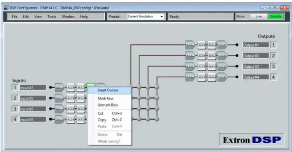
flowchart
graph TD
    A["Input #1"] --> B["Shift"]
    C["Input #2"] --> D["Shift"]
    E["Input #3"] --> F["Shift"]
    G["Input #4"] --> H["Shift"]
    B --> I["Insert Ducker"]
    D --> I
    F --> I
    H --> I
    I --> J["Mark Row"]
    I --> K["Unmark Row"]
    J --> L["Cut Ctrl+X"]
    J --> M["Copy Ctrl+C"]
    J --> N["Paste Ctrl+V"]
    J --> O["Delete Del"]
    J --> P["Whats wrong?"]
    L --> Q["Outputs"]
    M --> Q
    N --> Q
    O --> Q
    P --> Q
    Q --> R["Output #1 1"]
    Q --> S["Output #2 2"]
    Q --> T["Output #3 3"]
    Q --> U["Output #4 4"]
Figure 47. Selecting Ducking from the Context Menu
The Duck block is highlighted to indicate that a ducking processor block was inserted, and the Ducker Configuration dialog box opens (see figure 48 on the next page). When a ducking processor block is inserted, the Enable Source Mic/Line checkbox is automatically selected. (All inactive ducking processor blocks have Enable Source Mic/Line unchecked by default).
- Make adjustments to the ducking parameters as required.
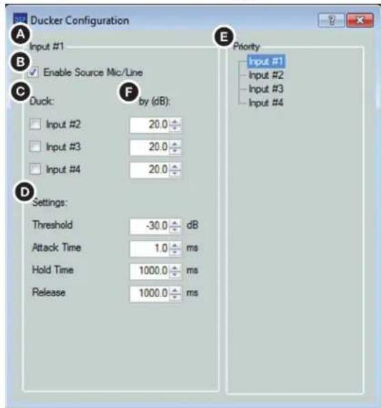
Figure 48. Ducker Configuration Dialog Box
A Current source indicator — Shows the selected input, for which the ducker settings are being entered. When a ducker dialog opens for a channel, the current source defaults to that channel. You can also select the current input by clicking the name in the Priority panel.
B Enable source mic/line check box — When this box is checked, ducking is enabled for the current source and the ducker processor block is highlighted. When the box is unchecked, ducking is disabled for the current source.
C Duck — Shows all potential input targets. Only inputs whose check boxes are selected are ducked. The current source is not available as a ducking target (a source cannot duck itself). If the current source has been designated as a target of another input channel, that channel is not available (a target cannot be the source).
D Settings — Used to configure the parameter settings for the ducker source. When a ducker block is copied, these settings are transferred.
- Threshold — Sets the input signal level in dB that the ducking source must exceed before ducking begins. If ducking does not occur soon enough to avoid loss of program material from the ducking source, decrease this setting. If ducking occurs too soon, allowing background noise to trigger ducking, increase it. The range is -60 to 0 dB in 1 dB increments. The default is -30 dB.
- Attack Time — Adjusts the time to duck the targets after the threshold is exceeded. The range is 0 to 3000 milliseconds in 1 millisecond increments. The default is 1 millisecond.
- Hold Time — Determines the time in milliseconds after a ducking source signal drops below the threshold before release time engages. The range is 0 to 10000 milliseconds in 1 millisecond increments. The default is 1000 milliseconds (1 second).
- Release — Determines the time in milliseconds that the ducking targets take to restore signal levels after the ducking source level is below the threshold and the hold time is met. The range is 10 to 10000 milliseconds in 1 millisecond increments. The default is 1000 milliseconds (1 second).
Priority — Displays the hierarchy of ducking source to duck targets. Priority levels are displayed in tree format. Input channels that are targets being ducked by a source are shown as indented below the source. Any input channel displayed in the tree is an active link. Click any input channel to select that channel as the current source. The current source indicator (figure 48, A, on the previous page) reflects the selected input channel.
F By (dB) — Individual attenuation settings for each duck target in dB. The default is 20.0 dB. If additional attenuation of the targets is required, increase this value. The attenuation range is 80.0 to 0.0 dB in 0.1 dB increments.
Priority
In some cases, multiple levels of ducking can be required to enable an input source to take precedence over all but one other input.
In the example in figure 49, inputs 2 and 3 are set to duck when input 1 has a signal above the ducking threshold. Input 2 is set to duck input 4. In the priority tree (see figure 48, E, on the previous page, or figure 49, E), the inputs are arranged by their priority status. Input 1 has inputs 2 and 3 under it. Therefore, if input 1 exceeds the threshold, it triggers inputs 2 and 3 to duck. Similarly, input 2 has input 4 under it. Therefore, if input 2 exceeds the threshold, it triggers input 4 to duck. Since input 2 has input 4 under it, input 1 triggers inputs 2, 3 and 4.
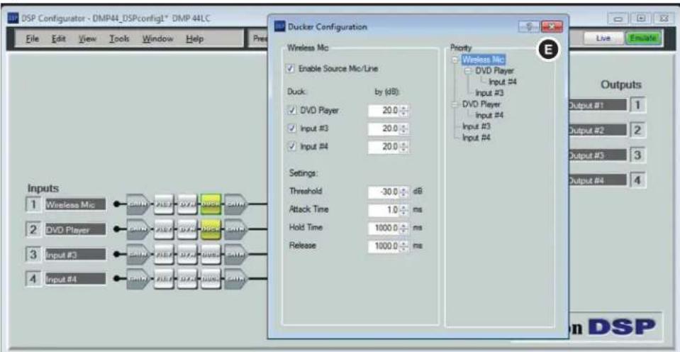
Figure 49. Ducker Configuration, Input Priority
Ducking attenuation is not additive. When an input target is ducked, regardless of how far down the priority line it is, the maximum attenuation is what is set in the “(dB):” column near the center of the dialog box (see figure 48, F, on the previous page).
Pre-mixer Gain block
The second Gain box in the Line Input chain is the pre-mixer gain control, which can be used to control program levels independent of microphone mixer levels. This gain control can also be used to compensate for any level changes due to processing. The default setting is unmuted at unity gain (0.0 dB).
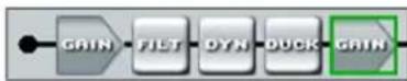
Figure 50. Pre-mixer Gain Box
To set the pre-mixer gain:
- Double-click the pre-mixer input Gain box. The Pre-mixer Gain dialog box opens.

Figure 51. Pre-mixer Gain Dialog Box
-
Click the fader handle or within the fader area to bring focus to the fader.
-
To adjust the input pre-mixer signal level, do any of the following:
-
Click and hold the fader handle, then drag it to the desired level in 0.1 dB steps (direct adjustment).
- Click or tab to the fader handle, then press the
or key to increase or decrease the level in 1 dB steps. Press the or key to increase or decrease it in 5 dB steps. -
Click in or tab to the signal level readout field. Type a new value, then either press the
key to select it or press the key to move to another area. -
Click OK to confirm the changes or Cancel to close the dialog box without making the changes.
Line Output Signal Chain
There are four mono line output channels. The channel controls and processing blocks described in this section are identical for each of the four outputs.

Figure 52. Line Output Controls
Output signal chain elements from left to right include:
- Trim (TRIM) — One post-mixer mono gain control per channel with a range of -12 dB to +6 dB, adjustable in increments of 0.1 dB.
- Filter (FILT) — Up to nine frequency filters can be inserted in any combination of High Pass, Low Pass, tone (Bass & Treble shelving), or Parametric Equalizer.
• Dynamics (DYN) — One limiter per block per channel. The limiter prevents clipping and protects a system against component or speaker damage.
• Volume (vOL) — One output volume control per channel with a range of -100 dB to 0 dB, adjustable in increments of 0.1 dB. Gain control is provided pre-meter. Mute control is provided post-meter. A Polarity button (click to toggle between + or -) is provided.
Trim block
The post-mixer Trim control can be used to fine-adjust the output volume. Each output TRIM block provides a single long-throw (large) fader with a gain range of -12 dB to +6 dB. The default setting is unity gain (0.0 dB).
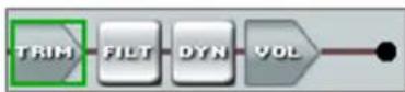
Figure 53. Trim Block
To adjust the output gain:
- Double-click the Trim block to open the Post-mixer Trim dialog box.
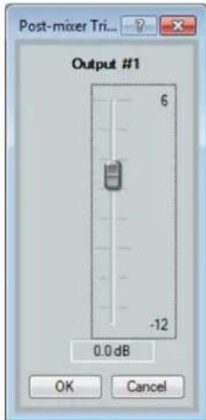
Figure 54. Post-mixer Trim Dialog Box
- Click the fader handle or within the fader area.
-
Adjust the level using any of the following methods:
-
Click and hold the fader handle, then drag it to the desired level in 0.1 dB increments.
- Press the
or key to respectively increase or decrease the level in 0.1 dB increments. - Press the
or key to respectively increase or decrease the level in 3 dB increments. -
Click in the level text field (resolution is 0.1 dB increments) and enter a new value. Press
or to move to another area of the dialog box. -
Click OK to accept the changes and close the dialog box, or click Cancel to close the dialog box without saving any changes.
Filter block — output
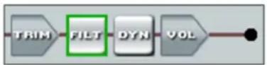
Figure 55. Output Filter Block
The output filter function and interface are identical to the line input channel filter block, except that there are a total of nine filters allowed in the output signal processor chain. See Filter block — input on page 23 for details on adding and configuring filter blocks.
Dynamics block — limiter (output)
Each output channel has a dynamics processor block that provides a limiter function when inserted. The limiter restricts the input signal level by compressing its dynamic range above a specified threshold. The limiter is most commonly used to prevent clipping, protecting a system against component or speaker damage. While the limiter is closely related to the compressor, it applies a much higher compression ratio of :1 . The ratio is fixed and cannot be changed.
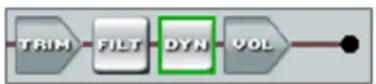
Figure 56. Output Dynamics Processor Block
To add and configure a limiter:
- Right-click on the Dyn block of the output to be configured, then select Insert Limiter from the context menu. The Limiter dialog box opens.
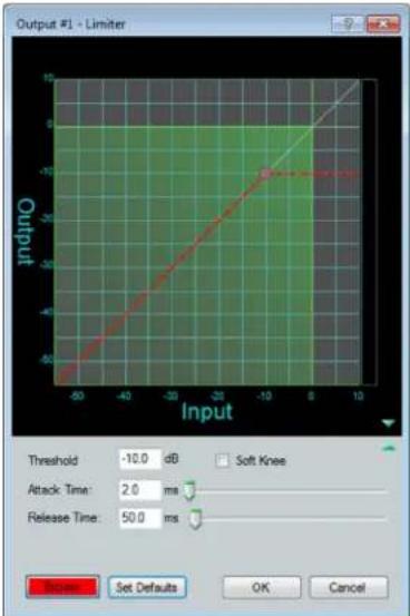
Figure 57. Limiter Dialog Box
-
Adjust the following settings as needed, then click OK when finished.
-
Threshold — Enter the input signal level above which limiting begins (subject to attack time) and below which compression stops (subject to hold and release time). Threshold level can be adjusted from -80.0 to 0.0 dB in 0.1 dB increments. The default is -10.0 dB.
- Attack Time — Enter the time delay for limiting to engage after the input signal level reaches or exceeds the threshold level. Attack time can be adjusted from 0.0 to 200.0 ms in 0.1 ms increments. The default is 2.0 ms.
- Release Time — Adjusts the time it takes to return the signal to normal (unprocessed) levels after the signal no longer exceeds the Threshold level setting. Release time begins only after hold time is reached. Release time can be adjusted from 10 to 1000.0 ms in 0.1 ms increments. The default is 50.0 ms.
- Soft Knee — Select this check box to smooth and soften the transition from uncompressed to compressed output levels.
Volume block
Each output channel volume block provides a mono long-throw fader with a range of 0 to 100 dB of attenuation, and a volume setting readout in dB below the fader. The default settings are 0 dB attenuation and unmuted. A peak meter displays the real-time audio level from -60 to 0 dBFS.
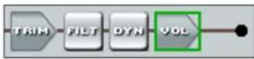
Figure 58. Volume Block
To adjust the volume:
- Double-click the Vol block for the desired output to open the Volume dialog box.
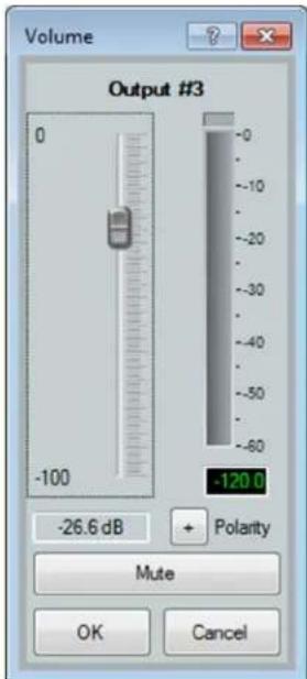
Figure 59. Volume Dialog Box
-
Adjust the volume using one of the following methods:
-
Click and drag the fader handle to the desired level.
- Press the
or key on the computer keyboard to respectively increase or decrease the level in 1 dB increments. - Press the
or key on the computer keyboard to respectively increase or decrease the level in 10 dB increments. -
Click in the level text field below the fader and enter a value in increments of 1 dB. Then, press the
or key to move to another area of the dialog box. -
Make adjustments to the following fields as needed:
-
Click the Mute button to mute the channel.
-
Click the Polarity button to toggle between positive (+) and negative (-) polarity.
-
Click OK to accept the changes and close the dialog box.
Click Cancel if you want to close the dialog box without saving any changes.
Configuring the Digital Input Ports
The 3-pole digital input connector provides three configurable input ports that are used to monitor or drive TTL level digital signals. The DSP Configurator software enables you to configure these ports.
To configure the digital input ports:
-
From the desktop Start menu, open the DSP Configurator by clicking Start > All Programs > Extron Electronics > DSP Configurator > DSP Configurator.
-
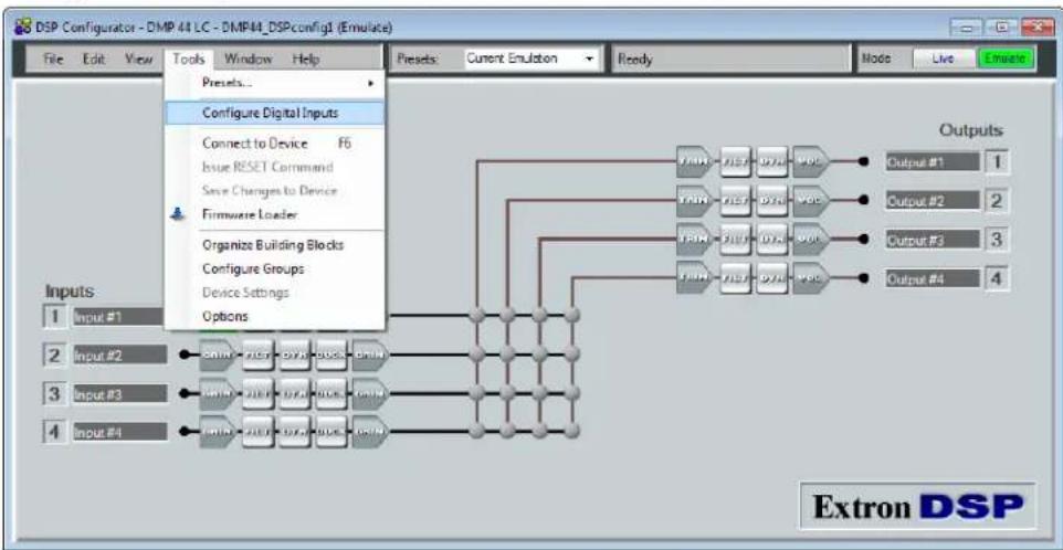
On the menu bar, select Tools > Configure Digital Inputs to access the Configuration utility.
flowchart
graph TD
    A["Input #1"] --> B["Connect to Device F5"]
    B --> C["Issue RESET Command"]
    C --> D["Save Changes to Device"]
    D --> E["Firmware Loader"]
    E --> F["Organize Building Blocks"]
    F --> G["Configure Groups"]
    G --> H["Device Settings"]
    H --> I["Options"]
    J["Inputs"] --> K["Outputs"]
    L["Extron DSP"] --> M["Output #1 1"]
    N["Inputs"] --> O["Outputs #2 2"]
    P["Inputs"] --> Q["Outputs #3 3"]
    R["Inputs"] --> S["Outputs #4 4"]
Figure 60. DSP Configurator Tools Menu
- From the Select Digital Input drop-down menu, select the digital input to configure.
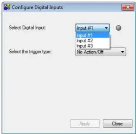
Figure 61. Selecting a Digital Input to Configure
- From the Select the trigger type drop-down menu, select the event that will trigger the action on the connected input device.
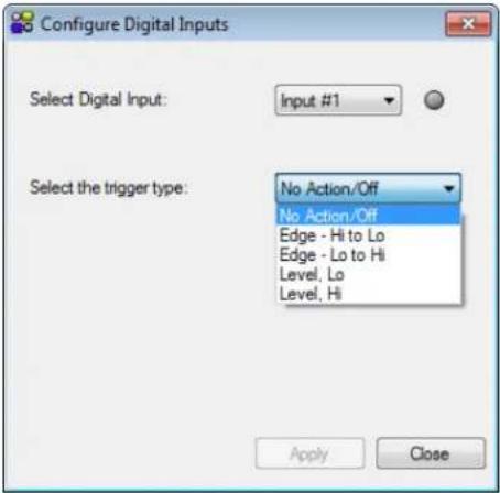
Figure 62. Selecting a Trigger Event
- From the Select function drop-down menu, select the action that results when the trigger event occurs.
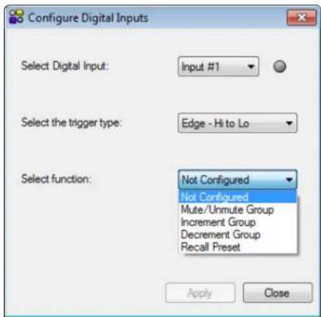
Figure 63. Selecting the Action to be Triggered
- From the Select the group to act upon drop-down menu, select the group on which the action is performed when the trigger event occurs.
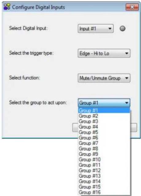
Figure 64. Selecting the Group on which the Action is Performed
- Select Apply to accept the changes.
Mix Matrix
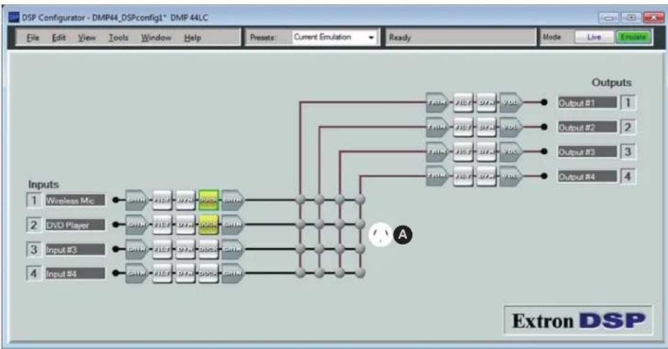
The DSP architecture contains a mix matrix through which incoming signals are routed to the line outputs (see figure 65, 1, on the next page). The mix matrix contains 16 mix-points, one for each input to each output bus. Each of the four line inputs is connected to a mix-point for each of the four line outputs, so that any or all of the four inputs can be routed to any or all of the four outputs. Each mix-point has a single fader with a range of -24 dB to +12 dB, adjustable in increments of 0.1 dB, plus a mute control.
Using the mix matrix, you can set mix levels from the post processing inputs to each line output bus. Mix levels are usually set relative to each other, achieving a desired blend of input signals at an optimal output level that is close to, but not exceeding 0 dBFS at the line output volume block level meter, while accounting for processing that can occur in the line output signal chain (see Line Output Signal Chain, beginning on page 35).
flowchart
graph TD
    A["Input 1: Wireless Mic"] --> B["AND"]
    C["Input 2: DVD Player"] --> D["AND"]
    E["Input 3: Input #3"] --> F["AND"]
    G["Input 4: Input #4"] --> H["AND"]
    B --> I["AND"]
    D --> J["AND"]
    F --> K["AND"]
    H --> L["AND"]
    I --> M["Output #1"]
    J --> N["Output #2"]
    K --> O["Output #3"]
    L --> P["Output #4"]
    M --> Q["Outputs"]
    N --> R["Outputs"]
    O --> S["Outputs"]
    P --> T["Outputs"]
    style A fill:#f9f,stroke:#333
    style C fill:#f9f,stroke:#333
    style E fill:#f9f,stroke:#333
    style G fill:#f9f,stroke:#333
Figure 65. Mix Matrix on the Audio I/O Workspace
Using the mix matrix
Mix-point status indicators
The status of each mix-point is reflected in the mix-point diagram as follows:
| Gray The mix-point is muted (contains no mix information). | 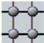 |
| Teal The mix-point is unmuted. | 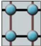 |
| Green circle A green circle appears around the mix-point when it is selected with a single click. | 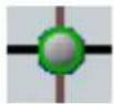 |
| Hand cursor The cursor changes to a hand when a mouse-over occurs at a mix-point whether or not the mix-point contains mix information. | 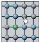 |
Routing inputs to outputs
To configure a mix-point to route an input to an output:
- Double-click the desired mix-point for the desired input-to-output routing. The Mix-point dialog box opens (see figure 66).
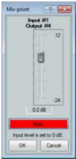
Figure 66. Mix-point Configuration Dialog Box
NOTE: Single-clicking a mix-point brings it into focus (selects it) but does not open the Mix-point Configuration dialog box.
- By default, the connection is muted. Click the red Mute button to unmute the input-output connection.
-
Adjust the mono fader as desired to set the level of the mix to the output bus. Gain range is -24 dB to +12 dB. You can use any of the following methods:
-
Click and hold the fader handle, then drag it to the desired level in 0.1 dB steps (direct adjustment).
- Click or tab to the fader handle, then
or to the desired level in 1 dB steps. Press the or key to increase or decrease the level in 5 dB steps. -
Click in or tab to the signal level readout field. Type a new value, then press
or to another area. -
Click OK to accept changes and close the window. (Click Cancel if you want to close the window without making changes.)
The title above the fader reflects the output channel name for the mix-point.
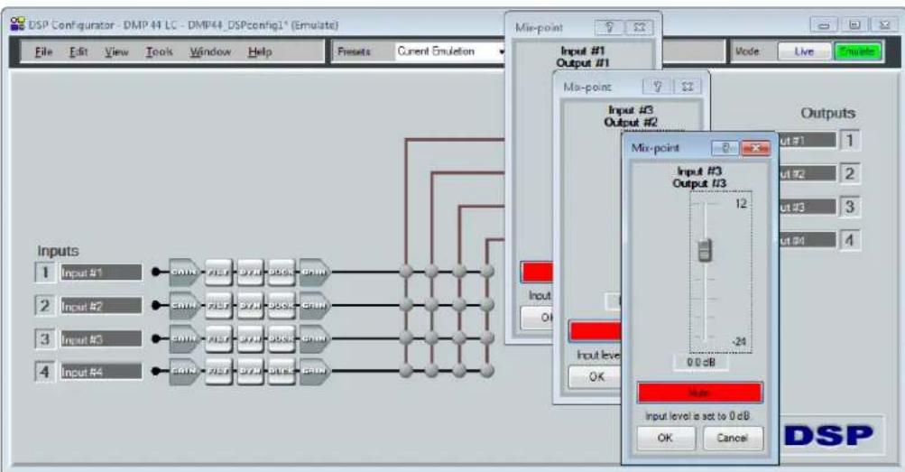
NOTE: You can have multiple mix dialog boxes open at the same time while you are configuring the mix-points (see figure 67 on the next page). When you open additional dialog boxes, the one most recently opened receives the focus. To focus on a previously opened box, either click on the box or on its mix-point.
flowchart
graph TD
    A["Inputs 1 Input #1"] --> B["EMIN"]
    C["Inputs 2 Input #2"] --> D["EMIN"]
    E["Inputs 3 Input #3"] --> F["EMIN"]
    G["Inputs 4 Input #4"] --> H["EMIN"]
    B --> I["BYD"]
    D --> J["BYD"]
    F --> K["BYD"]
    H --> L["BYD"]
    I --> M["SOCK"]
    J --> N["SOCK"]
    K --> O["SOCK"]
    L --> P["SOCK"]
    M --> Q["EMIN"]
    N --> R["EMIN"]
    O --> S["EMIN"]
    P --> T["EMIN"]
    Q --> U["EMIN"]
    R --> V["EMIN"]
    S --> W["EMIN"]
    T --> X["EMIN"]
    U --> Y["EMIN"]
    V --> Z["Output #1 Output #2"]
    W --> AA["Output #3 Output #2"]
    X --> AB["Output #3 Output #2"]
    Y --> AC["Output #3 Output #2"]
    Z --> AD["Output #3 Output #2"]
    AA --> AE["Output #3 Output #2"]
    AB --> AF["Output #3 Output #2"]
    AC --> AG["Output #3 Output #2"]
    AD --> AH["Output #3 Output #2"]
    AE --> AI["Output #3 Output #2"]
    AF --> AJ["Output #3 Output #2"]
    AG --> AK["Output #3 Output #2"]
    AH --> AL["Output #3 Output #2"]
    AI --> AM["Output #3 Output #2"]
    AJ --> AN["Output #3 Output #2"]
    AK --> AO["Output #3 Output #2"]
    AL --> AP["Output #3 Output #2"]
    AM --> AQ["Output #3 Output #2"]
    AN --> AR["Output #3 Output #2"]
Figure 67. Multiple Open Mix-point Dialog Boxes
Mix-point configuration examples
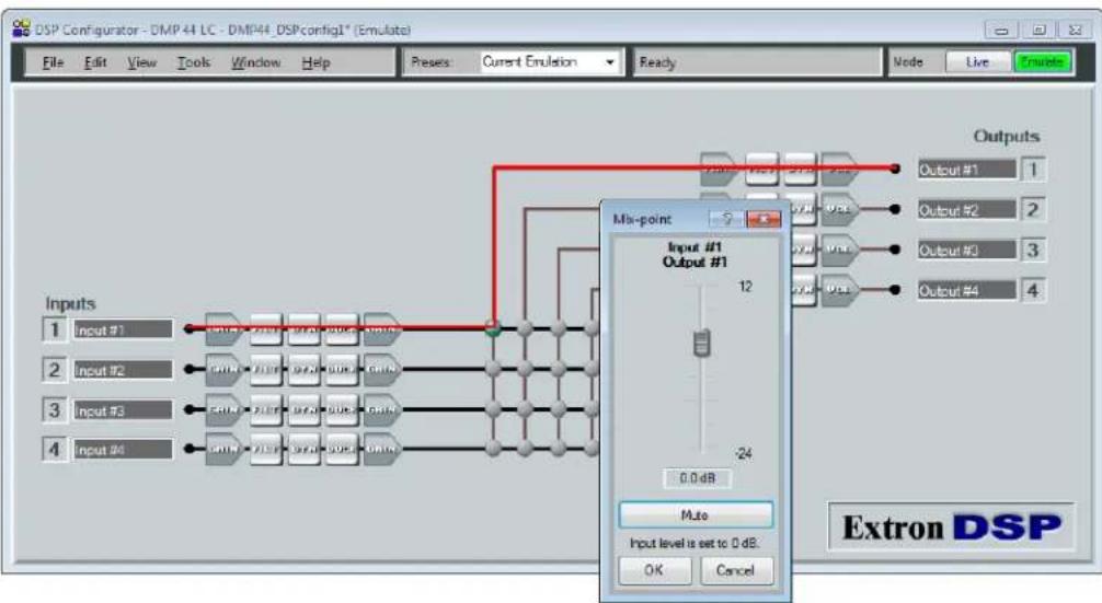
Example 1: In the example in figure 68, input audio from mic input 1 is processed and arrives at the mix-point. The mix-point is double-clicked to open the dialog box. On the dialog box, the mix is unmuted (the Mute button was clicked and is no longer red). On the mix matrix, the mix-point for input 1-output 1 becomes teal, indicating that it is unmuted and the signal is routed to output 1.
flowchart
graph TD
    A["Inputs 1 Input #1"] --> B["Input #2 Input #2"]
    B --> C["Input #3 Input #3"]
    C --> D["Input #4 Input #4"]
    D --> E["Output #1 Output #1"]
    E --> F["Mix-point"]
    F --> G["0.0 dB"]
    G --> H["Output #1 Outputs #1"]
    H --> I["0.0 dB Outputs #2"]
    I --> J["Output #3 Outputs #3"]
    J --> K["Output #4 Outputs #4"]
    K --> L["Extron DSP"]
Figure 68. Example 1 — Input 1 to Output 1 Mix
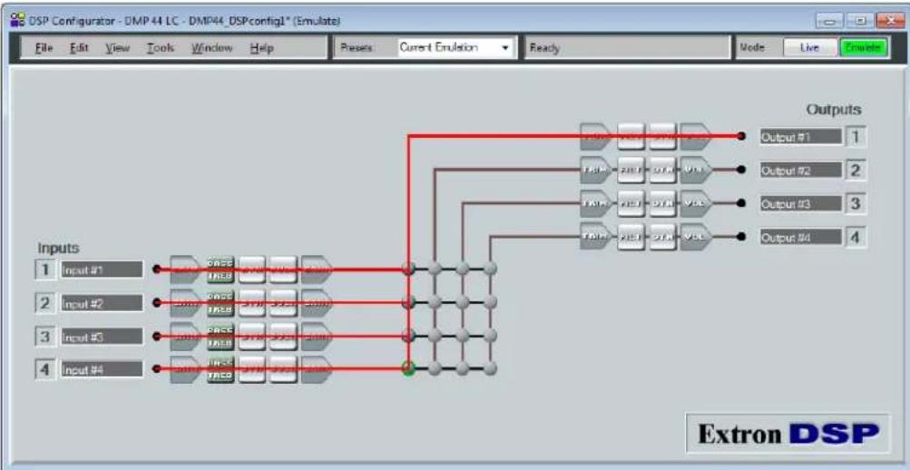
Example 2: In the example in figure 69, audio from all four line inputs is processed individually and arrives at the mix-points. The mix-points are teal to indicate the routing, and all four signals are routed to output 1. You can open the individual mix-point dialog boxes to adjust signal levels to the output.
flowchart
graph TD
    A["Input #1"] --> B["TRE"]
    C["Input #2"] --> D["TRE"]
    E["Input #3"] --> F["TRE"]
    G["Input #4"] --> H["TRE"]
    B --> I["VBL"]
    D --> I
    F --> I
    H --> I
    I --> J["Outputs"]
    style A fill:#f9f,stroke:#333
    style C fill:#f9f,stroke:#333
    style E fill:#f9f,stroke:#333
    style G fill:#f9f,stroke:#333
Figure 69. Example 2 — All Inputs to Output 1 Mix
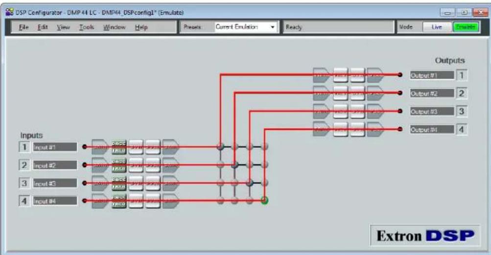
Example 3: In the example in figure 70, inputs 1 through 4 have been routed to outputs 1 through 4 by unmuting the mix-point for line input 1 on each output bus. Again, the mix-points are teal to indicate the routing.
flowchart
graph TD
    A["Input #1"] --> B["6000"]
    C["Input #2"] --> D["6000"]
    E["Input #3"] --> F["6000"]
    G["Input #4"] --> H["6000"]
    B --> I["Output 1"]
    D --> J["Output 2"]
    F --> K["Output 3"]
    H --> L["Output 4"]
    I --> M["Extron DSP"]
    J --> M
    K --> M
    L --> M
Figure 70. Example 3 — All Inputs to All Outputs
Presets
Presets created by DSP Configurator are used to recall a group of frequently used settings. They can contain all or a portion of the elements available within the program (gain blocks, processor blocks, and mix-points). In emulate mode, up to 16 presets can be created, then uploaded as a set and stored to the device or stored to the computer disk as a configuration file. In live mode, presets can be created one at a time from the current configuration. They can then be saved to a chosen preset number on the DMP with the option to name and save to the disk.
When recalled, a preset overwrites only elements contained in the preset. Presets are useful when settings for a particular room or only certain elements of a configuration need to be changed regularly.
Presets can be created in live or emulate mode. A preset added in live mode contains information taken from the current state of the DMP. A preset added in emulate mode contains information from the state of DSP Configurator (titled Current Emulation). Current emulation can be a configuration not yet saved as a preset (work in progress), the last preset or combination of presets recalled within DSP Configurator, or the current state of the device as a result of switching from live to emulate mode.
In emulate mode, the preset or presets are created, saved to a file, then pushed to the DMP 44 LC when it is connected in live mode.
When a pull data synchronization is performed (see Pulling or Pushing a Configuration and Selecting Live Mode on page 49), preset data remains on the DMP 44 LC with only the list of preset names pulled from the device. Presets in this state are marked with an asterisk until they are recalled (which pulls the preset data from the device), or until a backup is performed. Presets pulled from the device cannot be saved to the disk until they have been recalled, at which time the preset data is pulled into DSP Configurator. Presets with no asterisk can be saved to the disk.
Saved presets can be recalled via either the DSP Configurator or an SIS command.
Previewing and Recalling a Preset
You can preview a preset in either live or emulate mode as follows:
- From the Presets drop-down menu, select the name of a preset to preview.
The main screen displays the selected preset configuration with a translucent green mask over each element block that will be affected if the preset is recalled (applied). All other DSP Configurator elements are left unaltered. The Presets field displays the name of the selected preset.
In the example in figure 71 on the next page, preset 1 - Input Procs was selected. Only the input filter, dynamics processor, and ducker elements are included in this preset.
- Click the Recall button at the right of the Presets menu to apply the preset.
- In live mode: Real-time changes to the current state are not reflected on the screen while a preset is being previewed, and you cannot alter any elements. The Presets field displays Current State.
- In emulate mode — The viewed preset is applied to the current emulation. The preset field displays Current Emulation.
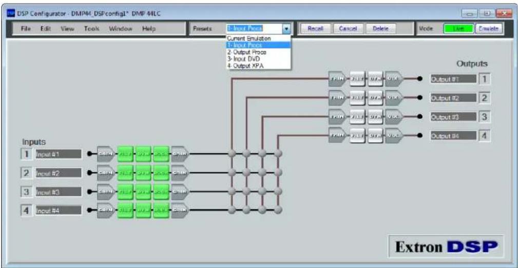
flowchart
graph TD
    A["Input #1"] --> B["EBIN"]
    C["Input #2"] --> D["EBIN"]
    E["Input #3"] --> F["EBIN"]
    G["Input #4"] --> H["EBIN"]
    B --> I["Output XPA"]
    D --> I
    F --> I
    H --> I
    I --> J["Outputs"]
    style A fill:#f9f,stroke:#333
    style C fill:#f9f,stroke:#333
    style E fill:#f9f,stroke:#333
    style G fill:#f9f,stroke:#333
Figure 71. Example — Previewing a Preset
Building a Preset
To create a preset:
- Highlight the desired DSP Configurator elements (processor blocks and mix-points) using the computer keyboard. Only elements that are highlighted (given focus) will be saved in the preset. Use any of the following methods as appropriate to select preset elements:
- Highlight all DSP Configurator elements on the screen:
- Press
+ . - Select Tools > Presets > Mark All Items.
This marks all elements within DSP Configurator, which saves a "full" preset.
- Select a single block: Left click on the desired block.
- Select multiple blocks that are not adjacent: Hold
while clicking on each desired block. - Select multiple adjacent blocks:
- Hold
- Click and drag a selected rectangle around the adjacent blocks in either a row or a column.
- Save the selection as described under Saving a Preset, on the next page.
Saving a preset
A preset can be saved in either emulate mode or live mode.
Saving a preset in emulate mode stores that preset in the currently open file. The DSP Configurator file must then be saved to the disk (recommended), or pushed to the device after a connection is established. This differs from live mode in which the created preset is saved in real time to the device and becomes part of the configuration file.
To save a preset:
- On the menu bar, select Tools > Presets > Save Preset.
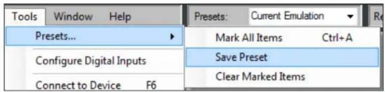
Figure 72. Saving a Preset
- In the Preset Number field in the Save a Preset dialog box, select or enter a preset number (1 through 16).
- In the Preset Name field, unassigned is shown for each preset number to which no preset has been saved. Select an unassigned preset number and enter a name of no more than 12 characters. If no name is entered, a default name is assigned. To overwrite an existing preset, select a preset with a name other than "unassigned."
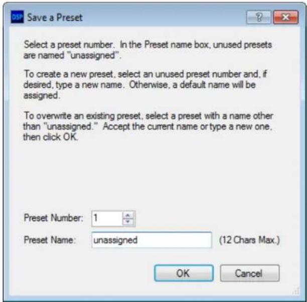
Figure 73. Save Preset Dialog Box
- Click OK to save the preset, or Cancel to stop the save process. The Save a Preset dialog box closes.
Managing Presets
After a preset is created (whether or not the DSP Configurator file is saved), its name appears on the preset list and can be selected from the Presets menu.
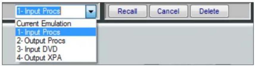
Figure 74. Presets Menu with Saved Presets
In both live and emulate modes, after a preset is selected from the list, the following action buttons become available on the menu bar next to the Presets field:
- Recall: Recalls (makes active or applies) the preset selected from the Presets menu.
- In Live mode: Applies the currently displayed preset elements (highlighted elements) from the stored preset and overwrites that portion of the current configuration. The Presets field displays Current State.
- In Emulate mode: Applies the currently displayed preset elements (highlighted) from the file and overwrites the information contained in DSP Configurator as the current emulation. The Presets field displays Current Emulation.
- Cancel: Cancels the preset selection and returns to the current emulation (emulate mode) or state (live mode).
- Delete: Deletes the selected preset.
- In Live mode: Deletes the preset from the hardware and removes it from the Presets list. After disconnecting from the device and before exiting the program, you must save the file if you want to retain this change.
- In Emulate mode: Deletes the preset from the file in the software. You must then save the file before exiting to retain the changes.
Pulling or Pushing a Configuration and Switching to Live Mode
When finished creating or editing and saving a configuration, you must switch to live mode to upload the configuration to the DMP. When switching to live mode after making changes to the current configuration in emulate mode, you can select to:
- Pull data from the device and update the DSP Configurator program configuration. This option downloads device settings from the DMP 44 LC and synchronizes it with the DSP Configurator program overwriting the current DSP Configurator settings.
- Push data from the DSP Configurator program to the device, overwriting settings on the DMP 44 LC.
Live mode can also be used to tailor audio settings in real-time while listening to the audio output.
To switch from emulate mode to live mode:
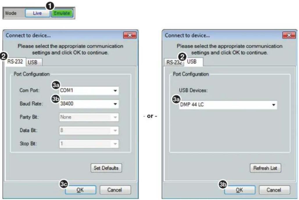
Figure 75. Selecting Live Mode with RS-232 or USB Connection
- On the main DSP Configurator screen, click the Live button (see figure 75, ①). The Connect to device... dialog box opens.
-
As needed, select either of the following tabs:
-
RS-232 ( ②) for connection to the rear panel RS-232 port. Proceed to step 3.
-
USB ( ③) for connection via the front panel Config port. Proceed to step 4.
-
If the RS-232 tab was selected in step 2:
a. Click the Com Port drop-down menu (4) and select the PC com port connected to the rear panel RS-232 port.
b. Check the baud rate displayed in the Baud Rate field (5). If the baud rate does not match the device rate, click the Baud Rate drop-down menu and select the desired baud rate. The default is 38400.
c. Click 0k.
If the USB tab (3) was selected in step 2:
a. Click the USB Device drop-down menu (6) and select DMP 44 LC (or Extron USB device if DMP 44 LC is not listed).
b. Click OK.
The Synchronize with Device dialog box appears. Several options are now available for either configuring the DMP 44 LC or reconfiguring to suit current operating conditions.
-
Select either of the following radio buttons:
-
Pull to update the current configuration with data from the device (1).
- Push to overwrite data on the device with this configuration (②).
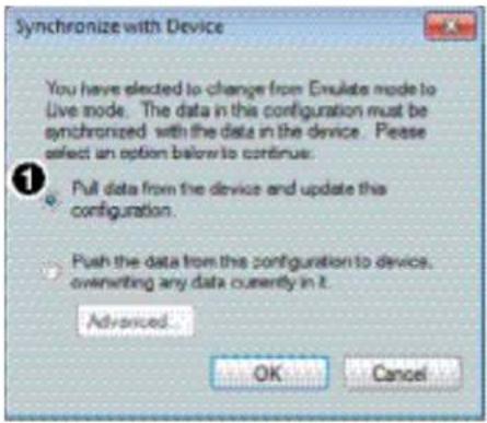
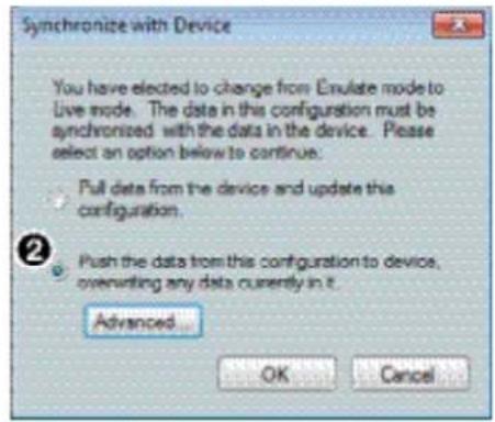
Figure 76. Synchronize with a Device Window
- Click OK. The DSP Configurator program is connected live to the device and the configuration and presets are pushed or pulled as selected.
NOTE: In either case, the program and device configuration now reflects DSP Configurator changes in real-time.
- If changes have been made to the DSP parameters (including mix-point, gain or processor blocks) since the last file save, DSP Configurator prompts to save the file. Click Yes or No, as necessary.
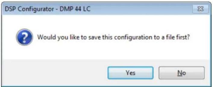
Figure 77. Synchronization Confirmation
- Click Yes to save the currently open configuration to an existing file or to create a new one, then proceed to step 7.
- Click No to push the currently open configuration to the DMP 44 LC. After the configuration is complete, DSP Configurator remains connected to the DMP 44 LC in live mode.
NOTE: If the file has been previously saved and has not changed, this step is skipped.
- Either enter a new file name or select an existing file from the list.
- Click Save. The DSP Configurator program uploads the current file to the DMP. The file overwrites the configuration of the device, and DSP Configurator is now connected live. Further changes to the configuration are reflected immediately in the device operation.
Pulling and Pushing Presets
When a preset is pulled from the device, the preset data remains in the device until the preset has been recalled. DSP Configurator pulls only the names of the presets. These presets cannot be saved to the disk until they have been recalled. An asterisk next to the preset name indicates that only the preset name has been pulled from the device, and the preset data only exists in the device (it has not been recalled).
Presets pushed to the device or created in DSP Configurator in live mode have no asterisk. Presets with no asterisk can be saved to the disk.
Using advanced options for pushing configurations
Some advanced options are available when you are pushing a configuration. These options enable you to tailor the input, signal processing, signal mix, or output to a specific preset operation. You can push the currently open configuration, including all presets, to the DMP or you can customize the configuration push to include either the configuration, selected presets, or both.
To use the advanced push feature:
- Connect the DMP 44 LC as described in steps 1 through 3 of the switching to live mode procedure on page 50.
- Select the Push radio button (see figure 78, ①).
- Click the Advanced button (②).
NOTE: Clicking OK at this time pushes the currently open configuration to the DMP 44 LC.
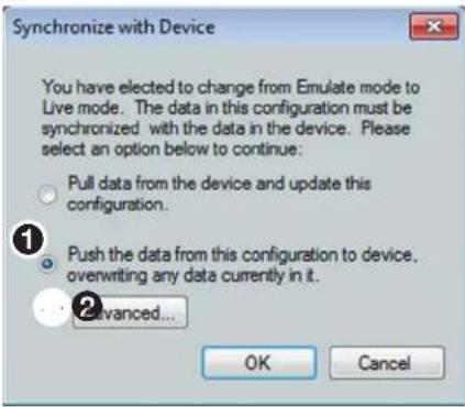
Figure 78. Synchronize with Device Dialog Box with Push Selected
-
Select one of the following radio buttons:
-
Select Default (see figure 79, ①) to update the device configuration with the currently open file, then skip to step 6.
- Select Custom ( ②) for additional options, then proceed to step 5.
NOTE: After either selection, the program and device configuration now reflect DSP Configurator changes to the DMP 44 LC configuration in real-time.
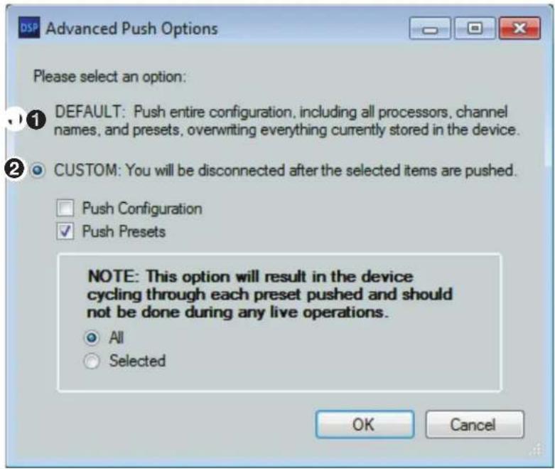
Figure 79. Advanced Push Options
- If you selected Custom, select either or both of the Push Configuration, or Push Presets checkboxes. In the example in figure 79, Push Configuration is not selected and all presets will be pushed.
- If you select both checkboxes or Push Presets only, two additional options are provided:
- A11: Uploads all stored presets from DSP Configurator to the device, overwriting previous presets.
- Selected: Uploads only the presets that you select (see Pushing selected presets on the next page for more information on this option).
- If you select only the Push Configuration checkbox, the additional options are grayed-out.
- Click OK. The Synchronize with Device dialog box appears.
- Leave all selections as they are and click OK again to push the presets to the device.
- If changes have been made to the DSP parameters (including mix-point, gain or processor blocks) since the last file save, DSP Configurator prompts you to save the file.
- Click Yes to save the currently open configuration to an existing file or to create a new one. The new configuration is pushed to the device.
Click No to ignore the file changes. The currently open configuration is pushed to the DMP 44 LC.
Pushing selected presets
To customize a configuration push to include only selected presets:
-
Connect the DMP 44 LC as described in steps 1 through 3 of the switching to live mode procedure on page 50.
-
On the Synchronize with Device dialog box, select the Push the data... radio button, then click Advanced.
NOTE: Clicking OK at this time pushes the currently open configuration to the DMP 44 LC.
-
In the Advanced Push Options dialog box, select the Custom radio button (see figure 80, ①).
-
Select the Push Presets checkbox (②).
-
Select the Selected radio button (③).
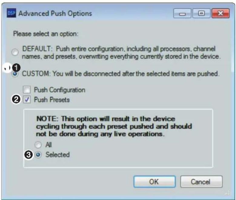
Figure 80. Advanced Options for Pushing Selected Presets
-
Click OK. The Synchronize with Device dialog box reappears.
-
Ensure that the Push the data... radio button is selected, then click OK.
-
If changes have been made to the DSP parameters (including mix-point, gain or processor blocks) since the last file save, the DSP Configurator prompts you to save the configuration file.
- Click Yes to open the Save configuration file as... dialog box. On this screen, accept the name, choose an existing file name, or create a new one for the configuration file and click OK. The new configuration is pushed to the DMP.
- Click No to ignore the changes. The currently open configuration is pushed to the DMP with no changes. After the configuration is complete, DSP Configurator remains connected to the DMP 44 LC in live mode.
The DSP Configurator presets dialog box opens.
- Select the preset configurations to push the DMP 44 LC. A checkmark appears for each selection. In this example, a checkmark has been placed in the 1. Input Procs and 4. Output XPA preset check boxes.
![DSP Configurator Select the presets you would like to push to the device. Presets in the Configuration ✓ Input Procs ☐ Output Procs ☐ Input DVD ✓ Output XPA ☐ Not Available ☐ Not Available ☐ Not Available ☐ Not Available ☐ Not Available ☐ Not Available ☐ Not Available ☐ Not Available ☒ ☒ Presets in the Device 1. Input Procs 2. [unassigned] 3. [unassigned] 4. Output XPA 5. [unassigned] 6. [unassigned] 7. [unassigned] 8. [unassigned] 9. [unassigned] 10. [unassigned] 11. [unassigned] 12. [unassigned] 13. [unassigned] OK Cancel](/content/2026/05/788965/images/6af9fce86af87a516d41fbafd7676a7f03f4efc316fadf033c0f983cd1c1db2e.jpg)
Figure 81. Selecting Presets
- Click OK. The DSP Configurator program saves the configuration then updates the configuration on the DMP, overwriting the configuration previously in the device. When the presets list dialog box closes, the upload is complete and the DSP Configurator program is connected live to the DMP 44 LC.
Changes to the configuration are reflected immediately in the device operation.
SIS Programming and Control
This section describes SIS programming and control of the DMP 44 LC, including:
- Connection Options
• DMP 44 LC-Initiated Messages
• Using the Command and Response Tables
• Command and Response Table for Basic DMP 44 LC SIS Commands
• Command and Response Tables for DMP 44 LC Audio SIS Commands
Connection Options
The DMP 44 LC can be configured and controlled using the Extron SIS (Simple Instruction Set) commands as an alternative to the DSP Configurator software (see Software Configuration beginning on page 11). The DMP can be connected to a host computer or other device (such as a control system) via the rear panel RS-232 port or the front panel USB Config port.
SIS commands can be sent to the DMP using the Extron Electronics DataViewer program, which can be downloaded from www.extron.com.
The protocol for the RS-232 port is:
• 38400 baud • No parity
- 8 data bits • No flow control
- 1 stop bit
See E RS-232 connector on page 8 for additional details on connecting to this port.
NOTES:
- The RS-232 port supports 38400 baud communication. This is a higher speed than that of many other Extron Electronics products. If using DataViewer or a similar application, make sure the PC or control system connected to these ports is set for 38400 baud.
- To use the front panel USB Config port, you must have installed the Extron USB driver (see Installing the USB Driver on page 13 for instructions).
DMP 44 LC-Initiated Messages
The DMP 44 LC initiates the following message under specific conditions. No response is required from the host. The following message is sent at power-up (RS-232 only):
(c) Copyright 20nn, Extron Electronics, DMP 44 LC, Vn.nn, 60-1095-01
Vn.nn is the firmware version number.
The DMP 44 LC sends the boot and copyright messages under the following circumstance: If the DMP 44 LC is off and an RS-232 connection is already set up (the PC is cabled to the DMP 44 LC and a serial communication program is open), the connected unit sends these messages via RS-232 when first powered on.
Using the Command and Response Tables
SIS commands consist of a string (one or more characters per command field). No special characters are required to begin or end a command sequence. When the DMP 44 LC determines a command is valid, it executes the command and sends a response to the host device. All responses end with a carriage return and a line feed (CR/LF = ←), signaling the end of the response character string.
When you are programming, certain characters are more conveniently represented by their hexadecimal rather than ASCII values. The following table shows the hexadecimal equivalent of each ASCII character:
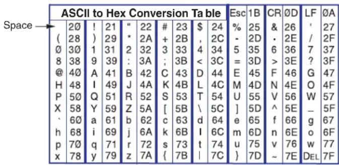
Figure 82. ASCII to Hex Conversion Table
Error Responses
When the DMP 44 LC is unable to execute the command, it returns an error response to the host. The error response codes and their descriptions are as follows:
Code Description Code Description
| E10 | Invalid command | E14 | Not valid for this configuration |
| E11 | Invalid preset | E17 | System timed out |
| E12 | Invalid port number | E22 | Busy |
| E13 | Invalid parameter (out of range) | E25 | Device is not present |
SIS Command Types
Although the DMP 44 LC uses the same structure for all SIS commands, there are two variations. One is the global command set documented in the Command and Response Table for Basic DMP 44 LC SIS Commands. The other set of commands, documented in the Command and Response Table for DMP 44 LC Audio SIS Commands (beginning on page 63), uses the same command structure but differs in how the software addresses the individual processor blocks within the DMP 44 LC.
Special Characters
The HTML language reserves certain characters for specific functions. The device does not accept these characters as part of preset names, the device name, or locally created file names.
The DMP 44 LC rejects the following characters:
{space} (spaces are acceptable in names) + \~ , @ = ' [ ] {} < > ' " semicolon (;) colon (:) | \ and ?.
Command and Response Table for Basic DMP 44 LC SIS Commands
Symbol Definitions
← = CR/LF (carriage return/line feed) (hex 0D 0A)
← or | = Carriage return (no line feed, hex 0D)
- = Space character
Esc or W = Escape key (hex 1B)
∞ = Future capability (not currently available)
[X1] = Version number Listed to two decimal places (for example, x.xx)
X2 = Version and Build number The least significant bits is the build number (for example, n.nn.nnnn)
[X3] = Verbose/Response 0 = clear or none
1 = verbose mode (broadcast, not tagged)
2 = tagged responses for queries (tagged, not broadcast)
3 = verbose mode + tagged responses for queries (tagged and broadcast)
Default = 1 for RS-232 or USB host control
NOTE: If "tagged responses" is enabled, all read or view commands return the constant string plus the data. For example:
Command: EscCN←
Response: Ipn●X12
[X4] = Baud rate = 9600
1 = 19200
2 = 38400 (default)
3 = 115200
X5 = Internal temperature Degrees Celsius
| X6 | = Dirty status | = RAM has been saved to Flash (OK to power off or reset)1 = RAM needs to be saved to Flash |
| X7 | = Unit name | A text string of up to 24 characters drawn from the alphabet (A-Z), digits ( -9), minus sign or hyphen (-). No blank or space characters are permitted as part of the name. No distinction is made between upper and lower case. The first character must be an alphabet character.The last character mustnotbe a minus sign or hyphen. |
| X8 | = Model name | |
| X10 | = Preset number | 1 - 16 |
| X12 | = Inputs | 1 - 4 |
| X13 | = Outputs | 1 - 4 |
| X14 | = Group number | 1 - 16 |
| X15 | = Parameter number | 6 = G12 = M |
| X16 | = Soft limit High value | |
| X17 | = Soft limit Low value | |
| X18 | = Group master value | For gain values with a resolution to 0.1, multiply by 10.Mute values: = mute , 1 = unmute. |
| X19 | = Digital inputs | 1 - 3 |
| X20 | = Type of signal change to monitor | = off (default)1 = edge, hi to lo2 = edge, lo to hi3 = level lo4 = level hi |
| X21 | = Function | = off (default)1 = mute or unmute2 = increment group3 = decrement group4 = preset recall |
| X22 | = Preset or group number | = off (default)1 - 16 = range |
| X23 | = State | = hi voltage1 = lo voltage |
NOTE: Commands can be entered back-to-back in a string, with no spaces. Example: NQ1I (show part number, firmware version, and model name)
Command and Response Table for Basic SIS Commands
| Command | ASCII Command (Host to Processor) | Response (Processor to Host) | Additional Description |
| General Commands | |||
| Information Requests | |||
| Query firmware version | Q | 1 | Show the current firmware version. |
| Query firmware and build version | *Q | 2 | Show the current firmware and build version. |
| Query part number | N | 60-1095-01← | Show the unit part number. |
| Query model name | 1I | DMP•44•LC← | Show the model name. |
| Query model description | 2I | Digital•Matrix•Processor← | |
| View internal temperature | 20S | 5 | Show internal temperature in degrees centigrade. |
| IP Setup | |||
| Set verbose mode | Esc X3 CV← | Vrb X3← | Set verbose/response mode. |
| View verbose mode | Esc CV← | 3 | View verbose mode |
| Set unit name | Esc X7 CN← | Ipn•X7← | Set the unit name. |
| Set unit name to factory default | Esc •CN← | Ipn•X8← | Set unit name to factory default. |
| Serial Port | |||
| Configure parameters | Esc X4 CP← | Ccp X4← | |
| View parameters | Esc CP← | 4 | View baud rate. |
| Ccp X4← | Verbose mode 2 and 3 | ||
| Reset | |||
| Delete presets and names | Esc ZG← | Zpg← | Delete all presets and names. |
| Delete an individual preset | Esc X10 ZG← | Zpg X10← | Delete specific preset. |
| System reset (factory default) | Esc ZXXX← | Zpx← | Reset system to factory default. |
| Absolute system reset | Esc ZQQQ← | Zpq← | Similar to system reset. |
| Commit only RAM to Flash | Esc 2FF← | Nvr X6← | Response appears when finished. |
| Query whether RAM needs to be saved to flash memory | Esc FF← X6← | ||
| KEY: | 1 = Version number n.nn 2 = Version number and build number n.nn.nnnn 3 = Verbose mode = clear or none | 1 = verbose mode (broadcast, not tagged) (default for RS-232 or USB host control) | 2 = tagged responses for queries (tagged, not broadcast)3 = verbose mode and tagged responses for queries (tagged and broadcast) |
| 4 = Baud rate = 9600 | 1 = 192002 = 38400 (default)3 = 115200 | ||
| 5 = internal temperature Displayed in degrees Celsius 6 = Dirty status = RAM has been saved to Flash (OK to power off or reset). | 1 = RAM needs to be saved to flash memory. | ||
| 7 = Unit name A text string up to 24 characters. 8 = Model name DMP -44 - LC 10 = Preset number 1 -16 | |||
| Command | ASCII Command (Host to Processor) | Response (Processor to Host) | Additional Description |
| General Commands (continued) | |||
| Name Commands | |||
| Write preset name | Esc X10, nameNG← | Nmg X10, name← | Write preset name. |
| Read preset name | Esc X10 NG← | name← | Read preset name. |
| Nmg X10, name← | Verbose modes 2 and 3 | ||
| Write input name | Esc X12, nameNI← | Nmi X12, name← | Write input name. |
| Read input name | Esc X12 NI← | name← | Read input name. |
| Nmi X12, name← | Verbose modes 2 and 3 | ||
| Write output name | Esc X13, nameNO← | Nmo X13, name← | Write output name. |
| Read output name | Esc X13 NO← | name← | Read output name. |
| Nmo X13, name← | Verbose modes 2 and 3 | ||
| Partial Preset Commands | |||
| Recall preset | X10. Rpr | X10← | Recall preset. |
| Group Master Commands | |||
| Group Master Name | |||
| Set name | Esc n X14* nameGRPM← | GrpmN X14* name← | Set name. |
| View name | Esc n X14 GRPM← | name← | View name. |
| GrpmN X14* name← | Verbose modes 2 and 3 | ||
| Set Master Value | |||
| Set + or - dB | Esc d X14* {+ or -} X18 GRPM← | ||
| GrpmD X14* X18← | Set + or -, | ||
| Set mute | Esc d X14* X18 GRPM← | GrpmD X14* X18← | Set mute. |
| Increment | Esc d X14* X18 +GRPM← | GrpmD X14* X18← | Increment master value. |
| Decrement | Esc d X14* X18 -GRPM← | GrpmD X14* X18← | Decrement master value. |
| View master value | Esc d X14 GRPM← | X18← | View master value. |
| GrpmD X14* X18← | Verbose modes 2 and 3 | ||
| View Group | |||
| View group members | Esc o X14 GRPM← | <OID>*<OID>...*<OID>← | View group members. |
| GrpmO X14*<OID>*<OID>... *<OID>← | Verbose modes 2 and 3 | ||
| View soft limits | Esc 1 X14 GRPM← | X16* X17← | View soft limits. |
| GrmpL X14* X16* X17← | Verbose modes 2 and 3 | ||
KEY:
X10 = Preset number 1 - 16
X12 = Inputs 1 - 4
X13 = Outputs 1 - 4
X14 = Group number 1 - 16
X16 = Soft limit (high value)
X17 = Soft limit (low value)
X18 = Group master value For gain values with a resolution to 0.1, multiply by 10.
For mute values, = mute, 1 = unmute
| Command | ASCII Command (Host to Processor) | Response (Processor to Host) | Additional Description |
| Digital Input Commands | |||
| Configure digital input | Esc X19 * X20 * X21 * X22 GPIT←Gpit X19 * X20 * X21 * X22← | For digital input X19, set signal change type X20 to monitor and function X21 to be performed. | |
| View digital input | Esc X19 GPIT← X20 | * X21 * X22←Gpit X19 * X20 * X21 * X22← | View digital input. |
| Verbose modes 2 and 3 | |||
| View I/O state | X19 ] | X23←Sio X19 * X23← | View I/O state. |
| Verbose modes 2 and 3 | |||
KEY:
X19 = Digital inputs 1 - 3
20 = Type of signal change to monitor = off (default)
1 = edge, hi to lo
2 = edge, lo to hi
3 = level lo
4 = level hi
X21 = Function = off (default)
1 = mute or unmute group
2 = increment group
3 = decrement group
4 = preset recall
X22 = Preset or group number 0 = off (default)
1 - 16 = range
X23 = State = hi voltage
1 = lo voltage
Command and Response Tables for DMP 44 LC Audio SIS Commands
Many digital signal processor (DSP) functions (gain, mute, and group masters) can be controlled using SIS commands. These commands follow the same general rules as basic SIS commands, but the variables can be more complex. A comprehensive understanding of the audio signal flow is helpful in understanding the commands. Figure 83 shows the specific DSP processors available for SIS commands.
NOTE: See DSP Processing and Signal Flow for a signal flow description.
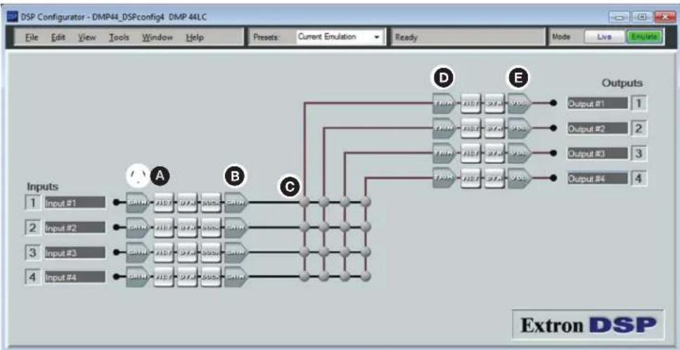
flowchart
graph TD
    A["Input #1"] --> B["CHIN"]
    C["Input #2"] --> D["CHIN"]
    E["Input #3"] --> F["CHIN"]
    G["Input #4"] --> H["CHIN"]
    B --> I["CHIN"]
    D --> J["CHIN"]
    F --> K["CHIN"]
    H --> L["CHIN"]
    I --> M["CHIN"]
    J --> N["CHIN"]
    K --> O["CHIN"]
    L --> P["CHIN"]
    M --> Q["CHIN"]
    N --> R["CHIN"]
    O --> S["CHIN"]
    P --> T["CHIN"]
    Q --> U["CHIN"]
    R --> V["CHIN"]
    S --> W["CHIN"]
    T --> X["CHIN"]
    U --> Y["CHIN"]
    V --> Z["CHIN"]
    W --> AA["CHIN"]
    X --> AB["CHIN"]
    Y --> AC["CHIN"]
    Z --> AD["CHIN"]
    AA --> AE["CHIN"]
    AB --> AF["CHIN"]
    AC --> AG["CHIN"]
    AD --> AH["CHIN"]
    AE --> AI["CHIN"]
    AF --> AJ["CHIN"]
    AG --> AK["CHIN"]
    AH --> AL["CHIN"]
    AI --> AM["CHIN"]
    AJ --> AN["CHIN"]
    AK --> AO["CHIN"]
    AL --> AP["CHIN"]
    AM --> AQ["CHIN"]
    AN --> AR["CHIN"]
    AO --> AS["CHIN"]
    AP --> AT["CHIN"]
    AQ --> AU["CHIN"]
    AR --> AV["CHIN"]
Figure 83. DSP Processors Addressable via SIS Commands
The DSP Configurator program window consists of an input signal processor chain, the mixer matrix, and an output signal processing chain. The following five processors can be controlled using SIS commands:
A Line input gain control — Provides level adjustment, mute, and polarity.
B Line input pre-mixer gain — Provides basic level adjustment after the input audio processing chain and prior to the mix-point.
C Mix-points — Provide level adjustment and signal routing from the inputs to the outputs.
Output trim control — Provides level adjustment after the line input audio processing.
E Output volume control — Provides volume control of the variable output, mute, and polarity.
Symbol Definitions — Audio Commands
| ← | = CR/LF (carriage return/line feed) (hex ∅D ∅A) |
| ← or | | = Carriage return (no line feed, hex ∅D) |
| ● | = Space character |
| Esc or W | = Escape key (hex 1B) |
NOTE: The dB values of the level settings are in 0.1 dB increments using negative numbers but not decimal places. Multiply the desired level setting by ten for the SIS command value. Example: To set an input level to 45.2 dB, use 452. To set an input level to -12.5 dB, use -125.
| X60 | = Gain and trim control or mix-point selection | Object identifier (OID) number that represents the selected gain and trim control or mix-point (see theLevel Control and Mix-point Selection Tableson the next page). |
| X61 | = Level value in dB dB value in 0.1 dB | increments, using negative numbers but not decimal places. The valid range depends on the type of gain and trim control block or mix-point specified in theX60command:1 = -180 through 240 (-18 to +24 dB)2 = -1000 through 60 (-100 to +6.0 dB)3 = -240 through 120 (-24 to +12 dB)4 = -120 through 60 (-12 to +6.0 dB)5 = -1000 through 0 (-100 to 0.0 dB) |
| X62 | = Signal polarity | 0 = Negative1 = Inverted |
| X64 | = Mute status 0 = unmute | 1 = mute |
| X65 | = Group master group number | ∅1-16 |
| X66 | = Group fader setting dB value in 0.1 dB | increments, using negative numbers but not decimal places. Leading zeros are ignored. The valid range depends on the type of gain block that is assigned to the group number (X65) specified in the command:1 = -180 through 800 (-18.0 dB to +80.0 dB)2 = -1000 through 120 (-100.0 dB to +12.0 dB)3 = -350 through 250 (-35.0 dB to +25.0 dB)4 = -120 through 120 (-12.0 dB to +12.0 dB)5 = -1000 through 000 (-100.0 dB to +0.0 dB) |
| X67 | = Group fader increment dB value, in 0.1 dB increments, to raise or lower a group fader | |
| X68 | = Group fader soft limit dB value, in 0.1 dB increments. The valid range X66 must be within the range for the gain block grouped in X65. | |
| X69 | = Group type 6 = gain | 12 = mute |
| X70 | = Personal Identification Number (PIN) Four numeric digits, default = 0000 | |
Level Control and Mix-point Selection Tables
The following tables show the object identifier numbers specified for the gain controls and mix-points for each input and output.
| 1 Input Gain Control | X60 Value |
| Input 1 | 30000 |
| Input 2 | 30001 |
| Input 3 | 30002 |
| Input 4 | 30003 |
| 2 Pre-mixer Gain | X60 Value |
| Input 1 | 30100 |
| Input 2 | 30101 |
| Input 3 | 30102 |
| Input 4 | 30103 |
| 3 Main Mix-point | X60 Value |
| Input 1 to Output 1 | 20000 |
| Input 1 to Output 2 | 20001 |
| Input 1 to Output 3 | 20002 |
| Input 1 to Output 4 | 20003 |
| 3 Main Mix-point | X60 Value |
| Input 2 to Output 1 | 20100 |
| Input 2 to Output 2 | 20101 |
| Input 2 to Output 3 | 20102 |
| Input 2 to Output 4 | 20103 |
| 3 Main Mix-point | X60 Value |
| Input 3 to Output 1 | 20200 |
| Input 3 to Output 2 | 20201 |
| Input 3 to Output 3 | 20202 |
| Input 3 to Output 4 | 20203 |
| 3 Main Mix-point | X60 Value |
| Input 4 to Output 1 | 20300 |
| Input 4 to Output 2 | 20301 |
| Input 4 to Output 3 | 20302 |
| Input 4 to Output 4 | 20303 |
| 4 Post-mixer Trim | X60 Value |
| To Output 1 | 60100 |
| To Output 2 | 60101 |
| To Output 3 | 60102 |
| To Output 4 | 60103 |
| 5 Post-mixer Output Volume | X60 Value |
| To Output 1 | 60000 |
| To Output 2 | 60001 |
| To Output 3 | 60002 |
| To Output 4 | 60003 |
Command and Response Table for Audio SIS Commands
| Command | ASCII Command (Host to Processor) | Response (Processor to Host) | Additional Description |
| Audio Level Control and Mix-point Selection | |||
| NOTES:The command format is the same regardless of the control or mix-point to be set; the acceptable adjustment range varies depending on the control or mix-point. See X61 in the previous section.All responses are shown with the DMP 44 LC in verbose mode 2 or 3. | |||
| Set a trim or gain (excluding line inputs) | Esc G X60 * X61 AU← | Dsg X60 * X61← | Set trim or mix controlX60 to X61 dB (seeLevel Control and Mix-point tables on the previous page. |
| Example 1(pre mixer gain) | Esc G30103*−8AU← | Dsg30103*−8← | Set pre-mixer 4 gain to a value of -0.8 dB. |
| Example 2(mix-point gain) | Esc G20001*165AU← | Dsg20001*165← | Mix +16.5 dB of line 1 into output 2. |
| Set a line gain | Esc G X60 * X61 AU← | Dsg X60 * X61← | Set line gain control X60 to a value of X61 dB. |
| Example: | Esc G30001*240AU← | Dsg30001*240← | Set the mic/line input 2 gain to a level of +24.0 dB. |
| Read a trim or mix (excluding line inputs) | Esc G X60 AU← | Dsg X60 * X61← | DSP trim or mix control X60 is set to a value of X61 dB. |
| Example 1(post mixer trim control) | Esc G60101AU← | Dsg60101*55← | Output 2, post mixer trim is set to a value of +5.5 dB. |
| Example 2(mix control) | Esc G20203AU← | Dsg20203*92← | +9.2 dB of line 3 is mixed into output 4. |
| Read a line gain | Esc G X60 AU← | Dsg X60 * X61← | View setting X61 of line gain control X60. |
| Example: | Esc G30000AU← | Dsg30000*550← | Line input 1 gain is set to a value of +55.0 dB. |
| Set signal polarity | Esc p X60 * X62 AU← | Dsp X60 * X62← | Set the signal polarity to X62 for control X60. For X62:∅ = positive (standard)1 = negative (inverted) |
| View signal polarity | Esc p X60 * AU← | Dsp X60 * X62← | View signal polarity X62 for control X60. |
KEY:
x60 = Gain and trim control or mix-point selection
X61 = Gain or trim level
See the Level Control and Mix-point Selection tables on the previous page.
① = -180 through 240 (-18 to +24 dB)
② = -1000 through 60 (-100 to +6.0 dB)
③ = -24∅ through 12∅ (-24 to +12 dB)
4 = -120 through 60 (-12 to +6.0 dB)
5 = -1000 through 0 (-100 to 0.0 dB)
X62 = Signal polarity
= positive (standard)
1 = negative (inverted)
| Command ASCII Command (Host to Processor) | Response (Processor to Host) | Additional Description | |
| Audio Mute | |||
| NOTES:Post-mixer trim (4 in theLevel Control and Mix-point Selection tableson page 65) cannot be muted.All responses are shown with the mixer device in Verbose mode 2 or 3. | |||
| Audio mute | EscM X60 *1AU← | DsM X60 *1← | Mute audio point X60. |
| Example: | EscM20301*1AU← | DsM20301*1← | Mute mix-point 4 to output 2. |
| Audio unmute | EscM X60 *0 AU← | DsM X60 *0← | Unmute audio point X60. |
| Read audio mute or level | EscM X60 AU← | DsM X60 * X64← | |
| Audio Group Master Commands | |||
| NOTES:A group must have assigned members for these commands to have an effect.For X66, a positive (+) value is assumed unless a negative (-) value is specified.If entering a X66 value outside the valid range for the group or outside the soft limits, the DMP 44 LC responds with an “invalid parameter” (E13) error code.X66, X67, and X68 values can be sent without leading zeros.SeeConfiguring Gain and Mute groups on page 18 andConfiguring Bass and Treble groups on page 20 for more information about audio group masters. | |||
| Set a group fader control | EscD X65 * X66 GRPM← | GrpmD X65 * X66← | Set the group fader to a value of X66. |
| Example: | EscD2* - 293GRPM← | GrpmD02* - 293GRPM← | Set the group 2 fader control to -29.3 dB. |
| Raise a group fader control | EscD X65 * X67 + GRPM← | GrpmD X65 * X66← | Increase the level of the X65 group fader by X67 dB. |
| Example: | EscD2*30+GRPM← | GrpmD02* - 263*GRPM← | Raise the group 2 fader 3 dB (from -29.3 dB to -26.3 dB, starting from the level set in the “Set a group fader control” example, above). |
KEY:
| X60 = Mix-point selection | See theLevel Control and Mix-point Selection tableson page 65. |
| X64 = Mute status | = unmute1 = mute |
| X65 = Group master group number | 1 - 16 |
| X66 = Group fader setting | 1 = -180 through 800 (-18.0 dB to +80.0 dB)2 = -1000 through 120 (-100.0 dB to +12.0 dB)3 = -350 through 250 (-35.0 dB to + 25.0 dB)4 = -120 through 120 (-12.0 dB to +12.0 dB)5 = -1000 through 000 (-100.0 dB through +0.0 dB) |
| X67 = Group fader increment | dB value in 0.1 dB increments. |
| Command ASCII Command (Host to Processor) | Response (Processor to Host) | Additional Description | |
| Audio Group Master Commands (continued) | |||
| Lower a group fader control | EscD X65 * X67 - GRPM← | GrpmD X65 * X66← | Decrease the level of the X65 group fader by X67 dB. |
| View the group fader control level | EscD X65 GRPM← | GrpmD X65 * X66← | In verbose modes 1 and 2, the response is simplified to X66←. |
| Mute a group mute control | EscD X65 *1GRPM← | GrpmD X65 *+1← | Mute all blocks in group X65. |
| Clear (unmute) a group mute control | EscD X65 *∅GRPM← | GrpmD X65 *+∅← | Unmute all blocks in group X65. |
| View a group mute control | EscD X65 GRPM← | GrpmD X65 * X64← | For group masters, X64 is expressed as a positive or negative value. |
| Set soft limits | EscL X65 * X68 upper * X68 lower GRPM← | ||
| GrpmL X65 * X68 * X68← | Set the groups soft limits to X68 and X68. | ||
| Example: | EscL2 *+6∅* - 6∅GRPM← | GrpmL2*6∅* -6∅← | Set the upper soft limit for the group 2 fader to +6.0 dB and the lower limit to -6.0 dB. |
| View soft limits | EscL X65 GRPM← | GrpmL X65 * X68 * X68← | In verbose modes 0 and 1, the response is simplified to X68 * X68←. |
| View group type | EscP X65 GRPM← | GrpmP X65 * X69← | Show the group type (X69) for group X65. In verbose modes 0 and 1, the response is simplified to X69←. |
| View group members | EscO X65 GRPM← | GrpmO X65 * X60 1* X60 2*... * X60 16← | X60 is the control or mix-point. In verbose modes 0 and 1, the response is simplified to X60 1* X60 2* X60 16←. |
KEY:
X60 = Mix-point selection 1 - 16
X64 = Mute status = unmute
1 = mute
X65 = Group master group number 1 - 16
[X66] = Group fader setting dB value in 0.1 dB increments using negative numbers but not decimal places. The valid range depends on the type of gain block that is assigned to the group number (X65) specified in the command
X67 = Group fader increment dB value in 0.1 dB increments.
68 = Group fader soft limit dB value in 0.1 dB increments. The valid range 68 must be within the range for the gain block grouped in 69 .
X69 = Group type 6 = gain 12 = mute
Reference Information
This section contains reference information for the DMP 44 LC. Topics in this section include:
- Mounting
- Updating the Firmware
Mounting
The 1U high, quarter rack width, 3-inch deep DMP 44 LC can be mounted in any of the following ways:
- Set on a table.
- Mounted on a rack shelf.
- Mounted under a desk or tabletop.
- Mounted on a projector bracket.
Tabletop Use
Each DMP 44 LC comes with rubber feet (not installed). For tabletop use, attach a self-adhesive rubber foot to each corner of the bottom of the unit.
UL Rack Mounting Guidelines
The following Underwriters Laboratories (UL) guidelines pertain to the safe installation of the DMP 44 LC in a rack.
- Elevated operating ambient temperature — If installed in a closed or multi-unit rack assembly, the operating ambient temperature of the rack environment can be greater than room ambient temperature. Therefore, install the unit in an environment compatible with the maximum ambient temperature (Tma = +122 °F, +50 °C) specified by Extron.
- Reduced air flow — Install the equipment in a rack so that the amount of air flow required for safe operation of the equipment is not compromised.
- Mechanical loading — Mount the equipment in the rack so that a hazardous condition is not achieved due to uneven mechanical loading.
- Circuit overloading — Connect the equipment to the supply circuit and consider the effect that circuit overloading might have on overcurrent protection and supply wiring. Appropriate consideration of equipment nameplate ratings should be used when addressing this concern.
- Reliable earthing (grounding) — Maintain reliable grounding of rack-mounted equipment. Pay particular attention to supply connections other than direct connections to the branch circuit (such as the use of power strips).
Rack Mounting
For optional rack mounting, do not install the rubber feet. Mount the DMP 44 LC on a 19-inch Universal 1U or Basic rack shelf.
To rack mount the DMP 44 LC:
- If rubber feet were previously installed on the bottom of the DMP 44 LC, remove them.
- Mount the DMP 44 LC on the rack shelf using two 4-40 x 3/16 inch screws in opposite (diagonal) corners to secure the unit to the shelf.
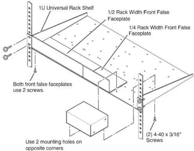
Figure 84. Mounting the DMP 44 LC on a Universal Rack Shelf
- Install black panels or other units on the rack shelf.
Furniture Mounting
Furniture mount the DMP 44 LC using the optional mounting kit as follows (see figure 85 on the next page):
- Attach the selected mounting brackets with the machine screws provided.
- If feet were previously installed on the bottom of the cabinet, remove them.
- Hold the unit with the attached brackets against the underside of the table or other furniture, or against the wall. Mark the location of the screw holes of the bracket on the mounting surface.
- Drill 3/32 inch (2 mm) diameter pilot holes, 1/4 inch (6.4 mm) deep in the mounting surface at the marked screw locations.
- Insert #8 wood screws into the four pilot holes. Tighten each screw into the mounting surface until just less than 1/4 inch of the head of the screw protrudes.
- Align the mounting screws with the slots in the brackets and place the unit against the surface, with the screws through the bracket slots.
- Slide the unit slightly forward or back, then tighten all four screws to secure it in place.
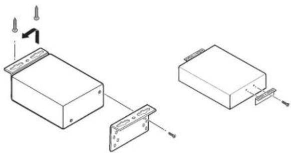
natural_image
Technical line drawing of two electronic components with screw fasteners and mounting brackets (no text or symbols)Figure 85. MBU 123, Under-desk Mounting
Updating the Firmware
Updates to the DMP 44 LC firmware are made available periodically on the Extron website. If the need arises, you can replace the firmware of the DMP 44 LC through a USB or an RS-232 connection.
After downloading the new firmware, upload it to the unit using the Extron Firmware Loader program. You can access the Firmware Loader by selecting it from the DSP Configurator Tools menu or by downloading it from the Extron website (see the Firmware Upgrade Page on the website for instructions).
To load firmware using the DSP Configurator Firmware Loader:
- Select Tools > Firmware Loader.
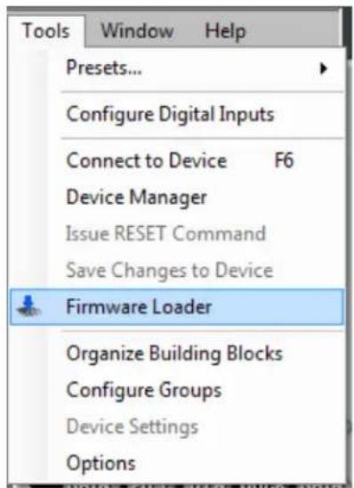
Figure 86. Firmware Loader Option on the Tools Menu
- The Add Device dialog box appears. Type the IP address of the DMP 44 LC, then click OK.
NOTE: If the IP has not been changed, the default IP address is 192.168.255.255.
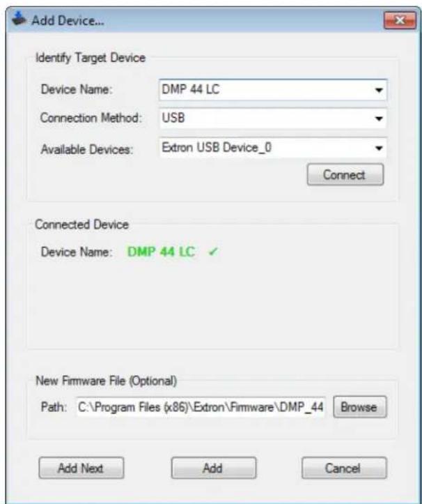
Figure 87. Add Device... Dialog Box
The Firmware Loader main screen appears.
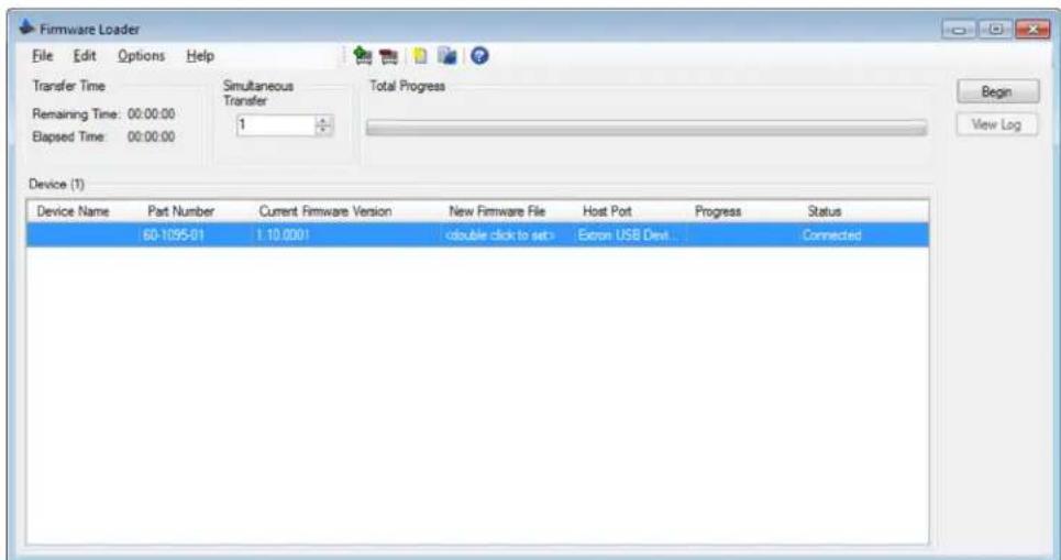
Figure 88. Firmware Loader Screen
-
From the Firmware Loader File menu, select Open.
-
In the Open window, locate the downloaded firmware file and double-click it.
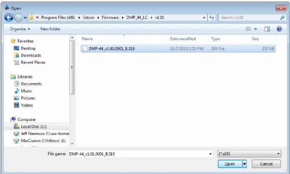
Figure 89. Firmware Open Window
- Click Begin on the main screen. The Total Progress bar tracks the loading progress. The Transfer Time panel displays the elapsed and remaining times for the upload.
- When the upload is finished, Completed appears above the Total Progress bar and the highlighted Progress section displays 100%.
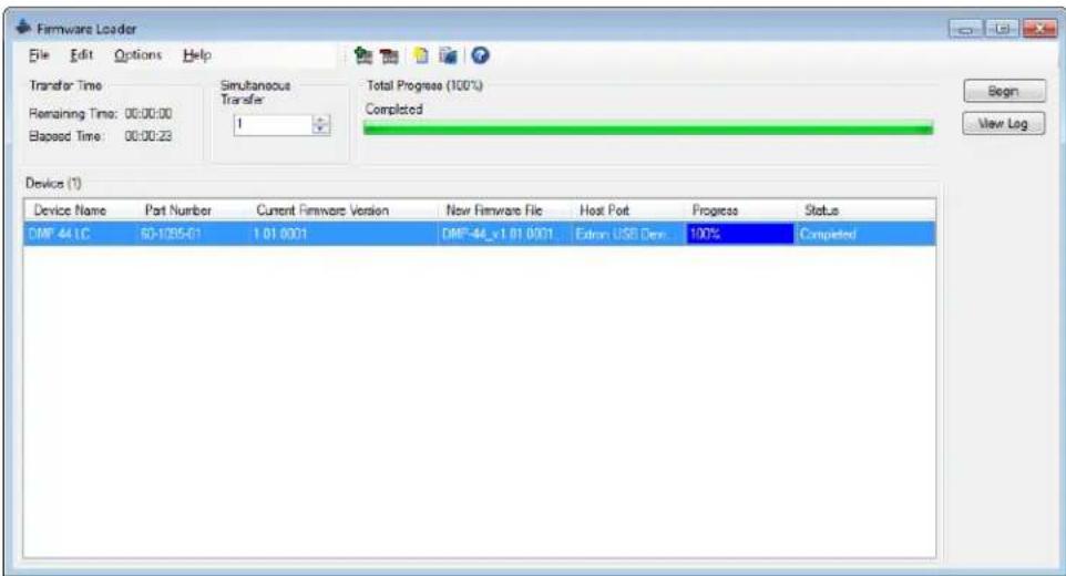
Figure 90. Firmware Loader Screen, Upload Completed
Exit the program by selecting File > Exit.
Extron Warranty
Extron Electronics warrants this product against defects in materials and workmanship for a period of three years from the date of purchase. In the event of malfunction during the warranty period attributable directly to faulty workmanship and/or materials, Extron Electronics will, at its option, repair or replace said products or components, to whatever extent it shall deem necessary to restore said product to proper operating condition, provided that it is returned within the warranty period, with proof of purchase and description of malfunction to:
USA, Canada, South America, and Central America:
Extron Electronics
1230 South Lewis Street
Anaheim, CA 92805
U.S.A.
Japan:
Extron Electronics, Japan
Kyodo Building, 16 Ichibancho
Chiyoda-ku, Tokyo 102-0082
Japan
Europe and Africa:
Extron Europe
Hanzeboulevard 10
3825 PH Amersfoort
The Netherlands
China:
Extron China
686 Ronghua Road
Songjiang District
Shanghai 201611
China
Asia:
Extron Asia Pte Ltd
135 Joo Seng Road, #04-01
PM Industrial Bldg.
Singapore 368363
Singapore
Middle East:
Extron Middle East
Dubai Airport Free Zone
F13, PO Box 293666
United Arab Emirates, Dubai
This Limited Warranty does not apply if the fault has been caused by misuse, improper handling care, electrical or mechanical abuse, abnormal operating conditions, or if modifications were made to the product that were not authorized by Extron.
NOTE: If a product is defective, please call Extron and ask for an Application Engineer to receive an RA (Return Authorization) number. This will begin the repair process.
USA: 714.491.1500 or 800.633.9876
Europe: 31.33.453.4040
Asia: 65.6383.4400
Japan: 81.3.3511.7655
Units must be returned insured, with shipping charges prepaid. If not insured, you assume the risk of loss or damage during shipment. Returned units must include the serial number and a description of the problem, as well as the name of the person to contact in case there are any questions.
Extron Electronics makes no further warranties either expressed or implied with respect to the product and its quality, performance, merchantability, or fitness for any particular use. In no event will Extron Electronics be liable for direct, indirect, or consequential damages resulting from any defect in this product even if Extron Electronics has been advised of such damage.
Please note that laws vary from state to state and country to country, and that some provisions of this warranty may not apply to you.
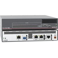
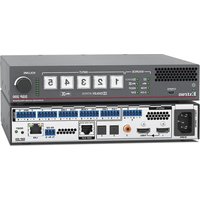
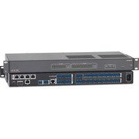
- DMP 44 LC
- Safety Instructions
- Safety Instructions • English
- Trademarks
- FCC Class A Notice
- Contents
- Introduction .... 1
- Installation and Operation....5
- Software Configuration ......11
- SIS Programming and Control ....56
- Reference Information......69
- Introduction
- About This Guide
- About the DMP 44 LC Digital Matrix Processor
- Features
- Installation and Operation
- Mounting the DMP 44 LC
- Rear Panel Features and Cabling
- ATTENTION:
- Front Panel Features
- Operations
- Powering On and Off
- Resetting
- Software Configuration
- About the DSP Configurator
- Defaults
- Gain Control
- Processing Tools
- Downloading and Installing the DSP Configurator Program
- Installing the USB Driver
- Starting the Program
- Operating Modes
- Configuring the DMP 44 LC
- Processor Blocks
- Line Input Signal Chain
- Line Input Gain block
- Configuring Gain and Mute groups
- Configuring Bass and Treble groups
- Filter block - input
- Parametric (equalizer) filters
- High Pass filter
- Low Pass filter
- Bass and treble tone filters
- Dynamics Processor block - input
- Compressor
- Ducking block
- Priority
- Pre-mixer Gain block
- Line Output Signal Chain
- Trim block
- Filter block — output
- Dynamics block — limiter (output)
- Volume block
- Configuring the Digital Input Ports
- Mix Matrix
- Using the mix matrix
- Mix-point status indicators
- Routing inputs to outputs
- Mix-point configuration examples
- Presets
- Previewing and Recalling a Preset
- Building a Preset
- Saving a preset
- Managing Presets
- Pulling or Pushing a Configuration and Switching to Live Mode
- Pulling and Pushing Presets
- Using advanced options for pushing configurations
- Pushing selected presets
- SIS Programming and Control
- Connection Options
- NOTES:
- DMP 44 LC-Initiated Messages
- Using the Command and Response Tables
- Error Responses
- SIS Command Types
- Special Characters
- Command and Response Table for Basic DMP 44 LC SIS Commands
- Symbol Definitions
- KEY:
- Command and Response Tables for DMP 44 LC Audio SIS Commands
- Symbol Definitions — Audio Commands
- Level Control and Mix-point Selection Tables
- Reference Information
- Mounting
- Tabletop Use
- UL Rack Mounting Guidelines
- Rack Mounting
- Furniture Mounting
- Updating the Firmware
- Extron Warranty
- USA, Canada, South America, and Central America:
- Japan:
- Europe and Africa:
- China:
- Asia:
- Middle East:
Brand : Extron
Model : DMP 44 LC
Category : Audio processor