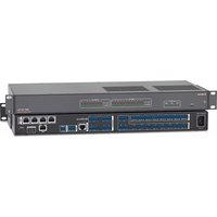
DMP 128 Plus C AT - Audio processor Extron - Free user manual and instructions
Find the device manual for free DMP 128 Plus C AT Extron in PDF.


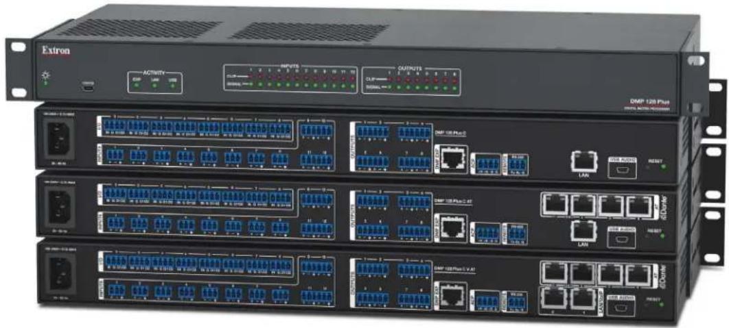
| Product Type | 12x8 ProDSP Digital Matrix Processor with Acoustic Echo Cancellation and Dante |
| Model Number | DMP 128 Plus C AT |
| Dimensions (H x W x D) | 1U (1.75" / 44.5mm) x 19" (482.6mm) x 8.5" (215.9mm) |
| Weight | Approximately 9.5 lb (4.3 kg) |
| Power Supply | 100-240 VAC, 50-60 Hz, internal |
| Inputs | 12 mic/line (inputs 1-8 on 3-pole 3.5mm, inputs 9-12 on 6-pole 3.5mm captive screw connectors) |
| Outputs | 8 line level (6-pole 3.5mm captive screw connectors) |
| Internal Mix Matrix | 52x48 |
| Dante Audio Network | 48 inputs (Rx) and 24 outputs (Tx) via a 4-port gigabit switch |
| Acoustic Echo Cancellation (AEC) | On input channels 1-8 (C models only) |
| USB Audio Interface | 4 channels send/return (48 kHz/16-bit) |
| Expansion Port (EXP) | 1 RJ-45 for linking two EXP-capable devices via shielded CAT 6 cable |
| Control Interfaces | RS-232 (3-pole 3.5mm), LAN (Gigabit Ethernet), USB Config, ACP port |
| Digital I/O | 8 configurable ports (4-pole 3.5mm captive screw) |
| Audio File Players | 8 players supporting WAV, AIFF, MP3 files up to 24-bit 48 kHz |
| Signal Processing | ProDSP with gain, filtering, dynamics, delay, ducking, automixing, and adaptive gain |
| Latency | 16 ms when fully loaded |
| Configuration Software | Extron DSP Configurator (Windows 7 or newer) |
| Mounting | Rack mount (1U), under-furniture, or free-standing with included rubber feet |
| Regulatory Compliance | FCC Class A, CE, UL listed |
| Operating Temperature | 0 to 50 °C (32 to 122 °F) |
| Maintenance | No user-serviceable parts; for battery replacement, return unit to Extron |
| Safety Warnings | Use only in commercial environments; risk of electric shock; do not expose to moisture |
Frequently Asked Questions - DMP 128 Plus C AT Extron
User questions about DMP 128 Plus C AT Extron
0 question about this device. Answer the ones you know or ask your own.
Ask a new question about this device
Download the instructions for your Audio processor in PDF format for free! Find your manual DMP 128 Plus C AT - Extron and take your electronic device back in hand. On this page are published all the documents necessary for the use of your device. DMP 128 Plus C AT by Extron.
USER MANUAL DMP 128 Plus C AT Extron
Mixers and Processors
DMP 128 Plus
12x8 ProDSP Digital Matrix Processor
natural_image
Extron network equipment chassis with multiple Ethernet ports and indicator lights (no readable text or symbols)Safety Instructions
Safety Instructions • English

WARNING: This symbol, ,when used on the product, is intended to alert the user of the presence of uninsulated dangerous voltage within the product's enclosure that may present a risk of electric shock.

TENTION: This symbol, when used on the product, is intended to alert the user of important operating and maintenance (servicing) instructions in the literature provided with the equipment.
For information on safety guidelines, regulatory compliances, EMI/EMF compatibility, accessibility, and related topics, see the Extron Safety and Regulatory Compliance Guide, part number 68-290-01, on the Extron website, www.extron.com.
© 2017-2018 Extron Electronics. All rights reserved.
Trademarks
All trademarks mentioned in this guide are the properties of their respective owners. The following registered trademarks (®), registered service marks (SM), and trademarks (TM) are the property of RGB Systems, Inc. or Extron Electronics (see the current list of trademarks on the Terms of Use page at www.extron.com):
| Registered Trademarks ^ |
| Extron, Cable Cubby, ControlScript, CrossPoint, DTP, eBUS, EDID Manager, EDID Minder, Flat Field, FlexOS, Glitch Free. Global Configurator, Global Scripter, GlobalViewer, Hideaway, HyperLane, IP Intercom, IP Link, Key Minder, LinkLicense, LockIt, MediaLink, MediaPort, NetPA, PlenumVault, PoleVault, PowerCage, PURE3, Quantum, Show Me, SoundField, SpeedMount, SpeedSwitch, StudioStation, System INTEGRATOR, TeamWork, TouchLink, V-Lock, VideoLounge, VN-Matrix, VoiceLift, WallVault, WindoWall, XTP, XTP Systems, and ZipClip |
| Registered Service Mark ^SM : S3 Service Support Solutions |
| Trademarks ^TM |
| AAP, AFL (Accu-Rate Frame Lock), ADSP (Advanced Digital Sync Processing), Auto-Image, CableCover, CDRS (Class D Ripple Suppression), Codec Connect, DDSP (Digital Display Sync Processing), DMI (Dynamic Motion Interpolation), Driver Configurator, DSP Configurator, DSVP (Digital Sync Validation Processing), eLink, Entwine, EQIP, Everlast, FastBite, FOX, FOXBOX, IP Intercom HelpDesk, MAAP, MicroDigital, Opti-Torque, PendantConnect, ProDSP, QS-FPC (QuickSwitch Front Panel Controller), Room Agent, Scope-Trigger, ShareLink, SIS, Simple Instruction Set, Skew-Free, SpeedNav, Triple-Action Switching, True4K, Vector ^TM 4K , WebShare, XTRA, and ZipCaddy |
FCC Class A Notice
This equipment has been tested and found to comply with the limits for a Class A digital device, pursuant to part 15 of the FCC rules. The Class A limits provide reasonable protection against harmful interference when the equipment is operated in a commercial environment. This equipment generates, uses, and can radiate radio frequency energy and, if not installed and used in accordance with the instruction manual, may cause harmful interference to radio communications. Operation of this equipment in a residential area is likely to cause interference. This interference must be corrected at the expense of the user.
Battery Notice
This product contains a battery. Do not open the unit to replace the battery. If the battery needs replacing, return the entire unit to Extron (for the correct address, see the Extron Warranty section on the last page of this guide).
CAUTION: Risk of explosion. Do not replace the battery with an incorrect type. Dispose of used batteries according to the instructions.
Conventions Used in this Guide
Notifications
The following notifications are used in this guide:
CAUTION: Risk of minor personal injury.
NOTE: A note draws attention to important information.
TIP: A tip provides a suggestion to make working with the application easier.
Software Commands
Commands are written in the fonts shown here:
^AR Merge Scene,,∅p1 scene 1,1 ^B 51 ^W^C.∅ [∅1] R∅∅4∅03∅0∅04∅0∅08∅0∅06∅0 [∅2] 35 [17] [∅3]
Esc X1 * X17 * X20 * X23 * X21 CE ←
NOTE: For commands and examples of computer or device responses used in this guide, the character “∅” is used for the number zero and “O” is the capital letter “o.”
Computer responses and directory paths that do not have variables are written in the font shown here:
Reply from 208.132.180.48: bytes=32 times=2ms TTL=32 C:\Program Files\Extron
Variables are written in slanted form as shown here:
ping xxx.xxx.xxx.xxx -t SOH R Data STX Command ETB ETX
Selectable items, such as menu names, menu options, buttons, tabs, and field names are written in the font shown here:
From the File menu, select New. Click the OK button.
Specifications Availability
Product specifications are available on the Extron website, www.extron.com.
Extron Glossary of Terms
A glossary of terms is available at http://www.extron.com/technology/glossary.aspx.
Contents
Introduction......1
About this Guide....1
About the DMP 128 Plus....1
Features 2
Application Diagram 3
Installation....4
DMP 128 Plus Models....4
Mounting 4
Rear Panel Features and Cabling....5
Front Panel Features....8
Hardware Reset Modes....9
Mode 1 — Firmware Reset......9
Mode 4 — IP Reset....9
Mode 5 — Factory Default Reset......9
DSP Configurator Software....10
Downloading and Installing DSP Configurator....10
Accessing the DSP Configurator Help File ...... 12
DSP Configurator Main Workspace 12
Menu Bar 13
File 13
Edit....14
View 14
Tools....15
Window 16
Help 16
Macros Drop-Down 17
Presets Drop-Down 17
DSP Configurator Status Panel....17
Live and Emulate Panel.... 18
DSP Configurator Inputs....21
Mic/Line Inputs....21
Naming an Input Channel 22
Input Building Blocks 22
Input Processing....24
Input Gain Block 24
Input Filter Block....26
Input AEC Block (C Models Only)......28
Input Dynamics Blocks 32
Input Delay Block....37
Input Ducking Block 38
Input Automix Block 40
Input Pre-Mixer Gain Block 42
Aux Inputs 43
Renaming an Aux Input 43
Aux Input Building Blocks 44
Aux Input Processing....44
Aux Input Gain Block 44
Aux Input Filter Block....47
Aux Input Dynamics Block 47
Aux Input Ducking Block.... 47
Aux Input Automix Block.... 47
Aux Input Pre-Mixer Gain Block 47
Virtual Returns 48
Renaming a Virtual Return 48
Virtual Return Building Blocks 49
Virtual Return Processing 49
Virtual Return Feedback Suppressor Block....49
Virtual Return Filter Block....53
Virtual Return Dynamics Block....53
Virtual Return Delay Block 53
Virtual Return Pre-Mixer Gain Block....53
Expansion and AT Inputs 53
Renaming an Expansion or AT Input 54
Expansion and AT Inputs Overview....54
Expansion and AT Inputs Processing....55
Mix-Points 55
Mix-Point Dialog Box 57
Mix-Point Context Menu 58
DSP Configurator Outputs....58
Outputs 59
Naming an Output 59
Output Building Blocks 59
Output Processing....60
Output Trim Block....61
Output Delay Block....61
Output Filter Block....61
Output Dynamics Block....62
Output Attenuation Block.... 62
Aux Outputs 63
Naming an Aux Output 63
Aux Output Processing....64
Aux Output Trim Block....64
Aux Output Filter Block....64
Aux Output Dynamics Block 64
Aux Output Gain Block 64
Expansion Outputs....65
Naming an Expansion Output 65
Expansion Output Processing....66
Expansion Output Trim Block....66
Expansion Output Delay Block....66
Expansion Output Filter Block....66
Expansion Output Dynamics Block....66
Expansion Output Attenuation Block 66
Virtual Send Bus....66
Configuration Tools....67
Presets....67
Methods for Marking Items 68
Configuring Presets 68
Groups 69
Configuring Groups 70
Digital I/O 72
Configuring Digital I/O....73
Players 75
Configuring Players....76
Macros....78
Configuring a Macro 79
Device Manager 82
Managing Devices in Device Manager......83
Connect to or Disconnect from Device 85
Firmware Loader 85
Downloading Firmware Updates....85
Organize Building Blocks....88
Device Settings.... 90
Unit Info....90
IP Settings 90
Passwords 91
Serial Settings 91
Date/Time 92
Dante Device 92
Options 93
Expansion Bus 94
Connecting the EXP Ports 94
Phone Dialer....96
Placing a Call with the Phone Dialer....97
Receiving a Call with the Phone Dialer ..... 97
Audio Control Panels (ACP) 98
ACP Panel Types 98
Panel ID #....99
ACP Panel Button Control Types 99
Action-Fixed 99
Action-Follow Selector....100
Selector-Vol/Mute (Selector)....100
Button Labels 100
Using Multiple ACP Panels 100
Configuration Examples....100
ACP 100 Configuration Example....101
ACP 106 Style Configuration Example ...... 103
Saving and Pushing ACP Configurations ..... 106
Dante Controller ....107
Overview 107
Downloading and Installing Dante Controller .... 108
Configuring the DMP 128 Plus AT in Dante
Controller....110
Device Name 110
Receiver and Transmitter Names 110
Dante Controller Naming Conventions ...... 110
Renaming the DMP 128 Plus AT in Dante
Controller....111
Renaming a Receiver or Transmitter...... 113
Finding a Dante Device IP Address 115
Physical Dante Network Setup 116
Redundant Configuration....117
Dante Controller Operation 118
Dante Transmitters and Receivers......118
Dante Routing Operation 119
Routing Devices.... 119
Disconnecting Inputs from Outputs....120
Dante Troubleshooting....121
Simplifying the Network for Troubleshooting 121
Troubleshooting the Network Interface......121
Restarting Dante Controller....122
Remote Communication and Control.....123
Connection Options....123
RS-232 Port 124
LAN Port 124
USB Config Port 125
Verbose Modes 125
Host-to-Device Communications....126
DMP 128 Plus-initiated Messages ...... 126
Using the Command and Response Tables ..... 127
Symbol Definitions 127
Error Responses....128
Simple Control Port Commands 128
Command and Response Table Sections ..... 129
Command and Response Table for Basic SIS Commands 129
DSP SIS Commands 141
Symbol Definitions....141
Special Characters 142
Command and Response Table for DSP SIS Commands 143
Command and Response Table for VoIP SIS Commands 148
Object ID (OID) Number Tables 150
Input Path OIDs 150
Output Path OIDs 151
Automixer OIDs 152
Mix-point OIDs.... 154
Web Pages....164
DMP 128 Plus Web Page 164
Accessing the Embedded Web Page......164
Using the Web Page....165
DMP 128 Plus VoIP Web Page....167
Accessing the Embedded VoIP Web Page...167
Using the VoIP Web Page....168
Special Characters 178
Introduction
This section describes this user guide and the DMP 128 Plus. The following topics are covered:
- About this Guide
• About the DMP 128 Plus - Features
• Application Diagram
About this Guide
This guide contains installation, configuration, and operating information for the Extron DMP 128 Plus ProDSP Digital Audio Matrix Processor. In this guide, the DMP 128 Plus may also be referred to as "DMP 128," "the mixer," or "device."
About the DMP 128 Plus
The Extron DMP 128 Plus Digital Audio Matrix Processor is a 12x8 audio mixer with broad I/O expansion capabilities including:
- 8 auxiliary inputs via VoIP (V models only), USB, and internal audio files
• 16 x16 expansion bus
• Dante 48x24 AT channels (AT models only) - VoIP (V models only)
- Digital I/O
The DMP 128 Plus features Extron ProDSP, automixing, AEC (Acoustic Echo Cancellation), and USB audio for use as an audio-to-PC interface. The DMP 128 Plus offers a configuration approach to DSP to simplify mixing, routing, conferencing, and room optimization. Quick and intuitive configuration using the Extron DSP Configurator software allows the DMP 128 Plus to be installed in very little time with easy-to-learn adjustments that can be applied in real-time. A digital audio expansion port (EXP) allows two EXP-capable devices to be linked together to expand input and output signal management and routing capabilities. The DMP 128 Plus is ideal for presentation and conferencing applications in boardrooms, courtrooms, and conference centers requiring advanced matrix mixing and DSP.
In addition to EXP expansion capabilities, DMP 128 Plus AT models allow connection to a Dante audio network for transporting audio across a TCP/IP network. This further increases the DMP 128 Plus input and output expansion capabilities.
DMP 128 Plus V models can register up to 8 VoIP lines per device. The DMP 128 Plus V can function as a VoIP interface, removing the need for dedicated VoIP hardware.
The DMP 128 Plus has no front panel controls. All configuration is performed using the Extron DSP Configurator software from a host computer via Ethernet (recommended) or USB. The rear panel RS-232 port allows for serial control via SIS commands. Signal presence and clip LEDs for the twelve input channels and eight output channels are on the front panel. Status indicators for EXP, LAN, and USB audio are also on the front panel.
Features
• 12 mic/line inputs — on 3.5 mm 3-pole and 6-pole captive screw connectors.
- 8 line level outputs — on 3.5 mm 6-pole connectors.
- Extensive 52x48 internal mix matrix —A single DMP 128 Plus can be used as the central audio processor for a sizeable system.
- USB audio interface — The DMP 128 Plus provides up to 4 channels of digital audio sends and returns for simplifying implementation of systems with soft-codec conferencing or computer based audio.
- AEC on input channels 1 - 8 (C models only) — Acoustic echo cancellation and selectable noise cancellation with advanced algorithms allow fast convergence in challenging situations including double-talk and the use of wireless microphones.
- VoIP capability supporting Session Initiation Protocol (V models only) — A single DMP 128 Plus V model can be used for a single VoIP line or as a VoIP farm for up to 8 rooms.
- AT models include 48x24 Dante™ digital audio network expansion — 48 Dante inputs (Rx) and 24 Dante outputs (Tx) via a 4-port gigabit switch allow flexibility in building large audio DSP systems with multiple DMP, AXP, and AXI units.
- Remote port for ACP control panels — For audio systems that do not need a full control system, Extron Audio Control Panels (ACP) offer flexible audio control, interfaced directly with the DMP 128 Plus. Available panels are: ACP 100, ACP 106 D, ACP 106 EU, and ACP 106 MK.
- Macros — Command sequences can be sent to the local device and external devices via the LAN port. This allows a single DMP 128 Plus to act as the central interface from a control system, sending commands to other DMP 128 Plus and DTP CrossPoint units.
- 8 Aux I/O ports — Configurable digital audio connectivity allows these ports to be configured as VoIP audio (V models only), USB communications audio, USB playback audio, or audio file players.
- Advanced audio processing on all 8 analog outputs and all 16 direct EXP outputs — Up to 24 speaker zones can be implemented on one DMP 128 Plus with full processing for each zone.
- 8 audio file players — Up to 8 audio file players can be used to play back audio files for system setup or as part of the system design. Pink noise, white noise, and sine waves are included with the device. Any WAV, AIFF, or MP3 files up to 24-bit 48 kHz can be uploaded.
- 16 virtual processing loops – Virtual loops allows great flexibility in sub-mixing and processing.
- Lower latency — Newer, faster, and more powerful DSP chips mean maximum performance resulting in a lower latency of 16 ms when fully loaded.
- Adaptive gain — A new adaptive gain processor that allows a given microphone input to affect levels on any one or all other inputs and virtual returns, ensuring background music and paging are the right volume, whether the room is quiet or noisy.
Application Diagram
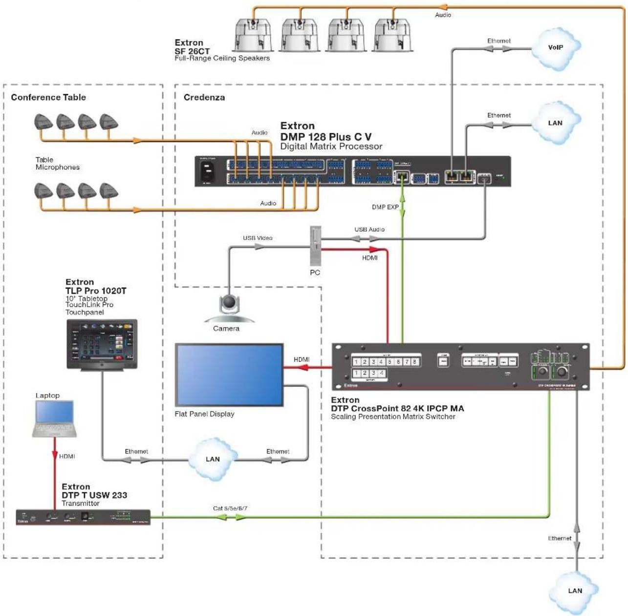
flowchart
Extron network architecture diagram showing connections between Extron SF 26CT, Extron DMP 128 Plus C V, and Extron DTP CrossPoint 82 4K IPCP MA modules with key devices like CPU, speakers, and Ethernet.Figure 1. DMP 128 Plus Application Diagram
Installation
This section describes the installation of the DMP 128 Plus and covers the following topics:
• DMP 128 Plus Models
- Mounting
• Rear Panel Features and Cabling
- Front Panel Features
• Hardware Reset Modes
DMP 128 Plus Models
| Model Description | |
| DMP 128 Plus 12x8 ProDSP Processor | |
| DMP 128 Plus C 12x8 ProDSP Processor with Acoustic Echo Cancellation (AEC) | |
| DMP 128 Plus C V 12x8 ProDSP Processor with AEC and VoIP | |
| DMP 128 Plus AT 12x8 ProDSP Processor with Dante | |
| DMP 128 Plus C AT 12x8 ProDSP Processor with AEC and Dante | |
| DMP 128 Plus C V AT 12x8 ProDSP Processor with AEC, VoIP and Dante | |
Mounting
The 1U high, full rack width, 8.5 inch deep DMP 128 Plus mounts in the following manners:
- Rack mounting — Attach the DMP 128 Plus to a standard 19-inch rack shelf. The following Underwriters Laboratories (UL) guidelines pertain to the installation of the DMP 128 Plus in a rack:
- Reduced air flow — Install the equipment in the rack so that the amount of air flow required for safe operation of the equipment is not compromised.
- Mechanical loading — Mount the equipment in the racks so that uneven mechanical loading does not create a hazardous condition.
- Circuit overloading — When connecting the equipment to the supply circuit, consider the effect that circuit overloading might have on overcurrent protection and supply wiring. Consider equipment nameplate ratings when addressing this concern.
- Reliable earthing (grounding) — Maintain reliable grounding of rack-mounted equipment. Pay particular attention to power supply connections other than direct connections to the branch circuit (such as the use of power strips).
- Under-furniture mounting — Mount the DMP 128 Plus under the surface of a desk, table, or podium.
- Free-standing — Attach the four rubber feet provided with the device to the bottom of the DMP 128 Plus in the four corners and place the unit on furniture as desired.
NOTE: To mount the DMP 128 Plus using an Extron mounting kit, see the instructions provided with the kit.
Rear Panel Features and Cabling
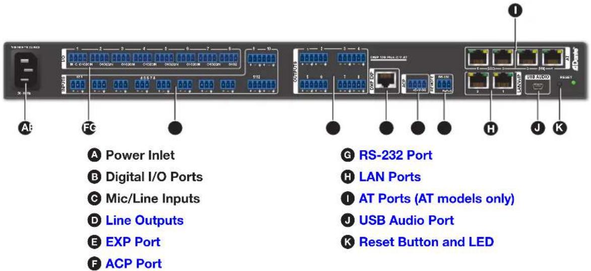
Figure 2. DMP 128 Plus Rear Panel
A Power Inlet — IEC power connection, 100 to 240 VAC, 50-60 Hz.
B Digital I/O Ports — Connect up to eight 4-pole 3.5 mm captive screw connectors. These configurable digital input and output ports are designed to connect to microphones with logic circuitry for mic mute and tally back functionality. Each port provides a common ground (see Digital I/O on page 72).
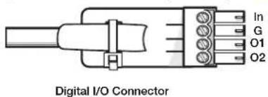
Figure 3. Digital I/O Connector
C Mic/Line Inputs — On inputs 1 through 8, use 3-pole 3.5 mm captive screw connectors to connect eight mono balanced or unbalanced microphone or line level sources (see figure 4 below for wiring). Inputs 1 through 8 provide AEC (C models only) and phantom power.
On inputs 9 through 12, use 6-pole 3.5 mm captive screw connectors to connect up to four mono balanced or unbalanced microphone or line level sources, or two stereo sources (see figure 5 below for wiring).
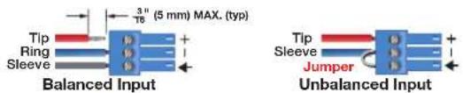
Figure 4. 3-pole Audio Input Wiring
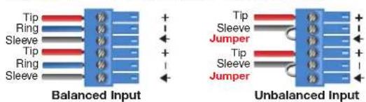
Figure 5. 6-pole Audio Input Wiring
ATTENTION:
D Line Outputs — Use 6-pole 3.5 mm captive screw connectors to connect up to eight mono balanced or unbalanced line level devices or four stereo devices (see figure 6 and figure 7 below for wiring).

Figure 6. 3-pole Audio Output Wiring
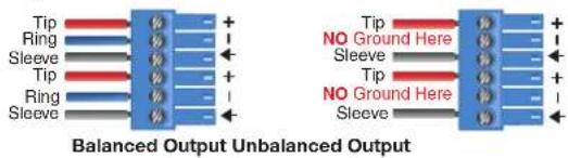
Figure 7. 6-pole Audio Output Wiring
ATTENTION:
- For unbalanced audio, connect the sleeves to the ground contact. DO NOT connect the sleeves to the negative (−) contacts.
- Pour l'audio asymétrique, connectez les manchons au contact au sol. Ne PAS connecter les manchons aux contacts négatifs (-).
E EXP Port — One RJ-45 port allows two units to be connected via a shielded CAT 6 cable to form a larger matrix system (1 foot cable included). Any Extron device with EXP capability can exchange audio with a DMP 128 Plus via the EXP port.
F ACP Port — Use a 4-pole 3.5 mm captive screw connector to connect an ACP control device for configuration via DSP Configurator (see Audio Control Panels (ACP) on page 98).
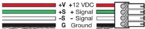
Figure 8. ACP Port Connector Wiring
G RS-232 Port — Use a 3-pole 3.5 mm captive screw connector to connect the host RS-232 cable for bidirectional RS-232 (±5V) serial control (see figure 9 below for wiring). The default baud rate is 38400.
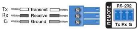
Figure 9. RS-232 Wiring Example
H LAN Ports — One (non-V models) or two (V models) RJ-45 ports provide a Gigabit network connection for control and VoIP traffic. The host PC or control system and the DMP 128 Plus must be connected to the same network. Two LEDs indicate status.
NOTE: Only DMP 128 Plus V models have two LAN/VoIP ports. Non-V models only have a single LAN port.
LAN 1 defaults:
| IP Address Subnet | Mask Default Gateway DHCP | |
| 192.168.254.254 255 | 5.255.255.0 0.0.0.0 OFF |
LAN 2 defaults:
| IP Address Subnet | Mask Default Gateway DHCP | |
| 192.168.1.254 255.2 | 55.255.0 0.0.0.0 OFF |
There are three ways the dual LAN ports can be configured on DMP 128 Plus V models:
- Control and VoIP traffic on one LAN port — Both control and VoIP traffic can be transported via a single LAN port.
NOTE: By default, control and VoIP traffic are both transported on LAN 1.
- Control and VoIP traffic on one LAN port using a VLAN — Both control and VoIP traffic can be transported via a single physical LAN port while utilizing a VLAN for VoIP traffic.
- Control and VoIP traffic on separate LAN ports — Control and VoIP traffic can be transported on separate LAN ports with unique IP configurations.
1 AT Ports (AT models only) — Four RJ-45 ports form a Gigabit switch for use with a Dante network. The AT ports use Dante protocol for digital audio transport (AT) and allow the DMP 128 Plus AT to connect to a Dante audio network to form a larger matrix (see Dante Controller on page 107). The 4-port switch can be configured as two 2-port switches for redundant Dante configuration. In redundant configuration, audio traffic is duplicated. Ports 3 and 4 are the primary switch (PRI), ports 1 and 2 are the secondary switch (SEC) (see Redundant Configuration on page 117).
USB Audio Port — One mini USB type B port connects to a computer and allows the DMP 128 Plus to function as a 4x4 audio interface with a Windows or Mac computer. Available sample rates are 48 kHz/16-bit.
Reset Button and LED —The reset button returns the DMP 128 Plus to different tiers of default states. When using the reset button, the LED blinks to signify the different reset modes (see Hardware Reset Modes on page 9). When not displaying reset modes, the LED operates as a power indicator, matching the front panel power LED.
Front Panel Features

flowchart
graph LR
    A["Extron"] --> B["Activity"]
    B --> C["INPUTS/OHPARG"]
    C --> D["CLP"]
    C --> E["Signal"]
    D --> F["DMP 128 Plus"]
    E --> F
    style A fill:#f9f,stroke:#333
    style B fill:#ccf,stroke:#333
    style C fill:#cfc,stroke:#333
    style D fill:#fcc,stroke:#333
    style E fill:#cff,stroke:#333
A Power LED
E USB Activity Indicator LED
B USB Config Port
F Input Indicator LEDs
© EXP Activity Indicator LED
G Output Indicator LEDs
D LAN Activity Indicator LED
Figure 10. DMP 128 Plus Front Panel
Power LED — Blinks during boot up and lights steadily when the DMP 128 Plus is operational.
B USB Config Port — One USB mini type B port is used for configuration. The USB config port can also be used for firmware updates.
EXP Activity Indicator LED — This green activity LED behaves differently depending on the model of DMP 128 Plus:
• non-AT Models
Off — The unit is not connected to a second EXP device.
On — The unit is connected to a second EXP device and is configured as the primary unit.
Blinking — The unit is connected to a second EXP device and is configured as the secondary unit.
- AT Models
On — The unit is connected to a second EXP non-AT device and is configured as the primary unit.
Blinking — The unit is not connected to a second device.
D LAN Activity Indicator LED — Blinks to indicate rear panel LAN port activity.
USB Activity Indicator LED —Blinks to indicate audio streaming over USB.
F Input Indicator LEDs — Stacked green and red LEDs display input signal presence and input signal clipping.
The green signal presence LED varies in brightness, corresponding to the real-time input signal level. It lights at -60 dBFS and increases in brightness until signal level reaches -3 dBFS. When the signal reaches or exceeds -3 dBFS, the red clip LED lights. The clip LED remains lit for 200 ms after receiving the clip signal.
Output Indicator LEDs — Stacked green and red LEDs display output signal presence and output signal clipping.
Output indicator LEDs function identically to the input indicator LEDs (see F above).
Hardware Reset Modes
NOTE: The reset modes listed below close all IP connections, Telnet connections, and sockets.
Mode 1 — Firmware Reset
Hold the Reset button while applying power to restore the unit firmware back to the default factory firmware. This recovers a unit that has incorrect code or updated firmware running. All user files and settings are maintained.
Mode 4 — IP Reset
With power on, press and hold the Reset button until the reset LED blinks twice (\~6 seconds). Release the button and, within 1 second, press it again to reset all IP address settings to factory default.
The following changes take place:
• ARP program capability is enabled
- Sets IP back to factory default (192.168.254.254)
- Sets subnet mask back to factory default (255.255.255.0)
- Sets gateway back to factory default (0.0.0.0)
- Turns DHCP off
- Sets digital I/O port mapping back to factory default
If a second momentary press does not occur within 1 second, Mode 4 is exited.
Mode 5 — Factory Default Reset
With power on, press and hold the Reset button until the reset LED blinks 3 times (\~9 seconds). Release the button and, within 1 second, press it again to return the DMP 128 Plus to factory default conditions.
The following changes take place:
- Sets all IP settings back to factory default (see Mode 4 above)
- Mix-points are set to unit gain (0 dBFS) and the following connections are made
- Input 1 is routed to output 1
• Input 2 is routed to output 2
• Input 3 is routed to output 3
• Input 4 is routed to output 4 -
Input 5 is routed to output 5
• Input 6 is routed to output 6
• Input 7 is routed to output 7
• Input 8 is routed to output 8 -
All audio inputs are set to unity gain
- All outputs are unmuted and set to unity gain
- Any inserted or active DSP is removed
- All preset and group master memory is cleared
DSP Configurator Software
The DMP 128 Plus has no front panel hardware controls. To configure and operate the DMP 128 Plus, use a PC running Microsoft® Windows® 7 or newer and Extron DSP Configurator software. This section describes Extron DSP Configurator software and covers the following topics:
- Downloading and Installing DSP Configurator
- Expansion and AT Inputs
- Accessing the DSP Configurator Help File • Mix-Points
- DSP Configurator Main Workspace • DSP Configurator Outputs
- Menu Bar • Outputs
- DSP Configurator Inputs
- Output Processing
• Mic/Line Inputs • Aux Outputs - Input Processing • Aux Output Processing
- Aux Inputs • Expansion Outputs
- Aux Input Processing • Expansion Output Processing
• Virtual Returns • Virtual Send Bus
• Virtual Return Processing
Downloading and Installing DSP Configurator
- From www.extron.com, click the Download tab (see figure 11, ①).
- On the left sidebar, click the DSP Configurator link (②).
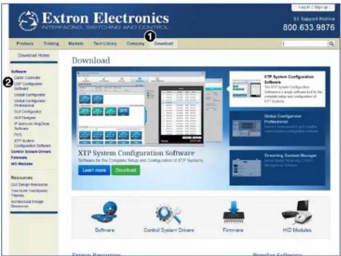
Figure 11. DSP Configurator Link on Download Page
- On the DSP Configurator Software page, click Download (see figure 12, ③). The Download Center page opens.
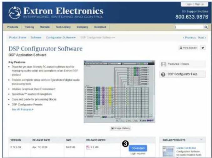
Figure 12. DSP Configurator Download Page
- From the Download Center page, DSP Configurator should begin downloading automatically. If it does not, select click here (see figure 13, 4).
NOTE: An Extron Insider account is required to download DSP Configurator and other software available from the Extron website. Login or account creation may be required before the Download Center page opens.
- Select Run (⑤) to run the DSP Configurator installer. Select Save to save the install file to run at a later time.
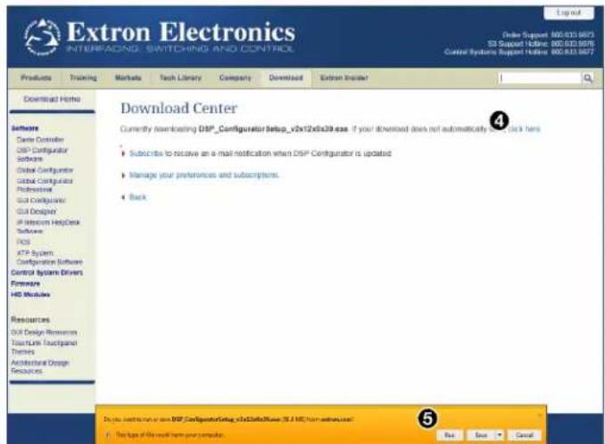
Figure 13. DSP Configurator Download Center Page
-
To run DSP Configurator from the default install location, click Start> Programs> Extron Electronics> DSP Configurator> DSP Configurator.
-
From the DSP Configurator splash screen drop-down menu (see figure 14, ⑥ below), select the model of DMP 128 Plus being connected to the host PC and click OK (⑦).
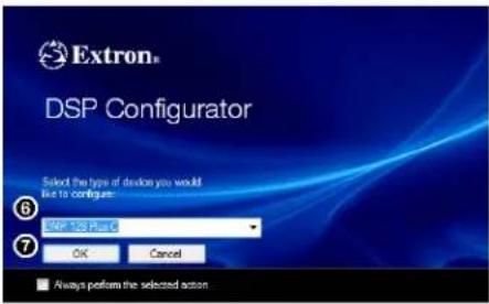
Figure 14. DSP Configurator Splash Screen
Accessing the DSP Configurator Help File
DSP Configurator comes loaded with a context-sensitive help file that can be accessed by clicking the help icon () in the top right corner of any dialog box in DSP Configurator. Alternatively, click Help > Contents in the menu bar at the top of the main workspace, or press
DSP Configurator Main Workspace
The DSP Configurator main workspace can be divided up into four main sections (see figure 15). Each section contains various functions to configure the DMP 128 Plus. Due to the large number of inputs and outputs available on the DMP 128 Plus, not all channels can be viewed at the same time in a single window. Use the expand and collapse buttons (☐) next to the input and output group names to show or hide input and output groups and their corresponding mix matrices. If necessary, scroll through the window by using the mouse wheel or the scroll bar at the right side of the DSP Configurator main workspace.
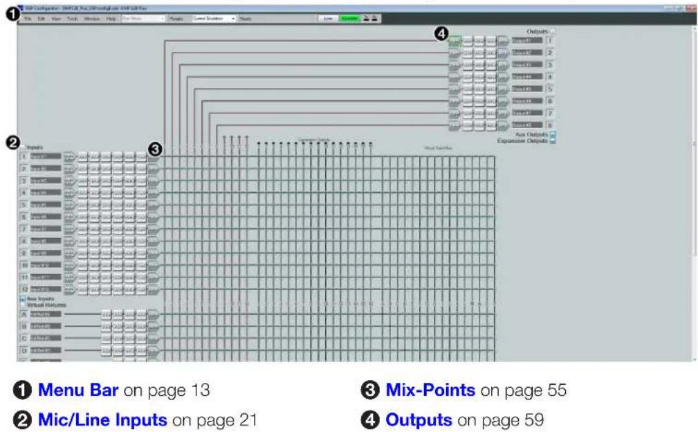
Figure 15. DSP Configurator Main Workspace
Menu Bar
File
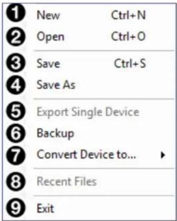
Figure 16. File Menu
1 New — Opens a new configuration file. This option is only available in Emulate mode (see Emulate Mode on page 18). If the current configuration has not been saved, the Save dialog box opens and asks to save the current configuration before a new configuration is opened. Click Yes to save the current configuration. Click No to delete the current configuration and open the new configuration. Click Cancel to return to the current configuration.
② Open — Opens an existing configuration or template file. When selected, the Browse dialog box opens to search for saved configuration or template files. Double-click a configuration or template file to load it.
NOTE: Configuration files have a .EDC file extension and template files have a .EDCT file extension.
③ Save — Saves the current configuration to a configuration file. If this is the first time the configuration is being saved, the Save Configuration As... dialog box opens. Enter a name and save location for the configuration file.
TIP: It is best to create and save configuration files while in Emulate mode.
4 Save As — Saves the current configuration file under a new name and location or as a template file. When selected, the Save Configuration As... dialog box opens.
⑤ Export Single Device — Saves the currently selected device in Device Manager as a configuration file. This function is used to save an individual device when there are multiple devices listed in the Device Manager (see Device Manager on page 82).
⑥ Backup — Recalls and transfers all partial presets of a DMP 128 to the configuration file or template file within DSP Configurator.
NOTE: This is only necessary if a DMP 128 (non-Plus) is included in the configuration file via Device Manager.
7 Convert Device to... — Select a model of DMP 128 Plus to which the current configuration file will be converted. After a conversion target model is selected, the Device Conversion dialog opens. For more information, refer to the DSP Configurator help file by clicking the context sensitive help (?) button in the dialog.
⑧ Recent Files — Lists the five most recently opened configuration files. These files can be selected and loaded into DSP Configurator.
9 Exit — Closes DSP Configurator. If the current configuration has not been saved, the Save dialog box opens and prompts the user to save the current configuration before closing the software. Click Yes to save the file. Click No to exit the application without saving. Click Cancel to return to the main workspace and keep the software running.
Edit

Figure 17. Edit Menu
① Cut — Removes the configuration of selected elements in the workspace to be pasted to other elements.
② Copy — Copies the configuration of selected elements in the workspace to be pasted to other elements.
③ Paste — Applies the cut or copied configuration of elements to the selected elements in the workspace.
View
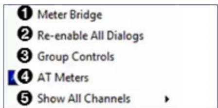
Figure 18. View Menu
① Meter Bridge — Opens a meter bridge to view input and output activity. The meter bridge is a floating window, allowing use of the DSP Configurator workspace while simultaneously monitoring input and output activity.
NOTE: The meter bridge is only available in Live mode with a TCP/IP connection.
② Re-enable All Dialogs — This option re-enables all dialog boxes that no longer appear based on user selection (certain dialog boxes that appear are user-defeatable by selecting a checkbox that reads Do Not Show This Dialog Again).
③ Group Controls — Opens the Group Controls dialog box to access existing group controls and add new groups.
4 AT Meters (AT models only) — Opens a dialog box to select AT devices on the network. Double-click a device to open a meter bridge dialog box that displays AT transmit (Tx) and receive (Rx) channel levels for that device. The dialog box is a floating window, allowing use of the main workspace while simultaneously monitoring AT levels.
⑤ Show All Channels — Individual channels can be hidden by user selection. This provides options for the user to select which input and output groups are visible in the main workspace.
Tools
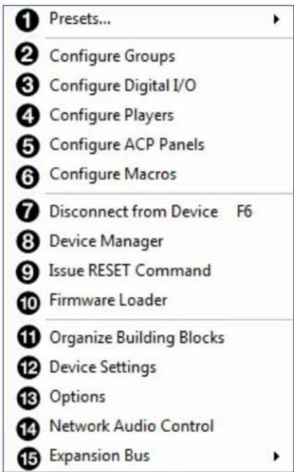
Figure 19. Tools Menu
① Presets — Contains a submenu to mark and clear elements in the main workspace as well as an option to save marked elements to a preset (see Presets on page 67).
② Configure Groups — Opens the Configure Groups dialog box to create, edit, and delete Gain, Mute, Bass, and Treble groups (see Groups on page 69).
③ Configure Digital I/O — Opens the Configure Digital I/O dialog box to assign actions and modes to the digital inputs and outputs (see Digital I/O on page 72).
4 Configure Players — Opens the Configure Players dialog box to upload audio files and assign them to players. Player control options are also found in the dialog box (see Players on page 75).
⑤ Configure ACP Panels — Opens the Configure ACPs dialog box to configure Extron Audio Control Panel interfaces (see Audio Control Panels (ACP) on page 98).
⑥ Configure Macros — Opens the Configure Macros dialog box for creating, editing, and deleting macro functions (see Macros on page 78 for more information).
7 Connect/Disconnect from Device — When in Emulate mode, this reads Connect to Device and opens the Connect to Device dialog box (see Connect to or Disconnect from Device on page 85). When in Live mode, this reads Disconnect from Device and returns the software to Emulate mode.
⑧ Device Manager — Opens the Device Manager dialog box (see Device Manager on page 82).
⑨ Issue RESET Command — Clears the DMP 128 Plus of all processors and other configuration settings. This command does not reset general settings such as IP address.
10 Firmware Loader — Opens the Firmware Loader application, if it is installed (see Firmware Loader on page 85). Visit www.extron.com to download the software.
11 Organize Building Blocks – Opens the Organize Building Blocks dialog box (see Organize Building Blocks on page 88).
12 Device Settings — Opens the Device Settings dialog box to edit date and time, IP address, DHCP status, and other settings (see Device Settings on page 90).
13 Options – Opens the Options dialog box to configure DSP Configurator appearance, default settings, DSP value defaults, and so on (see Options on page 93).
14 Network Audio Control — Opens the Dante Controller application by Audinate for routing audio over a Dante network (see Dante Controller on page 107).
15 Expansion Bus – Contains a submenu to assign a DMP 128 Plus as a Primary or Secondary unit. On DMP 128 Plus AT models, the submenu can assign the expansion ports to AT channels 33-48 (see Expansion Bus on page 94).
Window
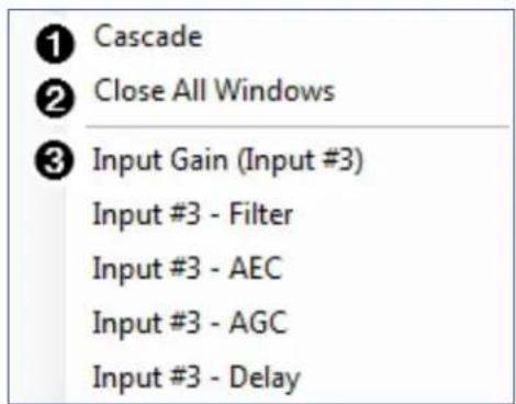
Figure 20. Window Menu
① Cascade — Organizes windows by cascading them in the same order they were opened.
② Close All Windows — Closes all open windows, leaving only the main workspace visible. When all windows are closed, changes to parameters in the open windows are saved before the window is closed.
③ List of Open Windows — Below the dividing line is a list of all open windows. Select a window from the list to bring it into focus and to the forefront of the workspace. Windows appear in the order they were opened.
Help
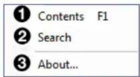
Figure 21. Help Menu
① Contents — Opens the DSP Configurator Help file where detailed information about DSP Configurator can be found.
② Search — Opens the DSP Configurator Help file with the Search field in focus.
③ About — Opens a window displaying software version number, copyright information, and part number for the installed copy of DSP Configurator. Click the Details button for a list of advanced details, such as build number.
Macros Drop-Down
The Run Macro drop-down list is available when connected to the DMP 128 Plus in Live mode. The drop-down list is unavailable in Emulate mode.
The Run Macro drop-down list allows the user to view and run all macros that have been pushed to the device. The list of macros updates dynamically when a new macro is created. Macros created in DSP Configurator that have not been pushed to the device appear in the list with an asterisk to the right of the macro name. Only macros that have been pushed to the device can be run from the Run Macro drop-down list (see Macros on page 78 for information on configuring macros).
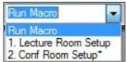
Figure 22. Macros Drop-Down Menu
Presets Drop-Down
The Presets drop-down menu allows the user to view and apply presets saved in the current configuration file or on a device connected in Live mode. Presets with an asterisk next to them are on the DMP 128 Plus, but not in the current configuration file. Run a preset to load it into the configuration file. Alternatively, perform a backup to run all presets and load them into the current configuration file (see File on page 13).
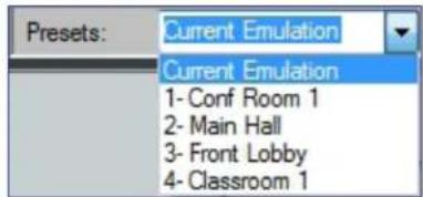
Figure 23. Presets Drop-Down Menu
After selecting a preset from the list, choose one of the following actions from the DSP Configurator status panel:
Recall — Recalls the selected preset and applies settings to the main workspace.
Cancel — Cancels the preset recall and returns to the main workspace with the current emulation or state intact.
Delete — Deletes the selected preset from the configuration.

Figure 24. Preset and Action Selection
DSP Configurator Status Panel
This panel displays the current status of DSP Configurator and shows when data is being pushed to or pulled from the device. When the software is ready to perform actions, the panel reads Ready.

Figure 25. DSP Configurator Status Panel
Live and Emulate Panel
The Live and Emulate buttons allow users to switch between Live and Emulate mode and displays transmit activity (Tx) and receive activity (Rx) when in Live mode.

Figure 26. Mode Panel
Emulate Mode
While in Emulate mode, DSP Configurator is functioning in an "offline" state. Changes made to the configuration file are not applied to a DMP 128 Plus.
In Emulate mode, the user can create and configure the software as though a device was connected, except for any actions that require direct connection to the device or information that is stored only on the device. Once configuration is complete, the user can switch to Live mode and apply the configuration to the device or save the configuration file to be loaded onto one or multiple devices at a later time.
Creating configuration files in Emulate mode saves time by not requiring a device to be connected or present in order for the bulk of DSP configuration to be completed.
NOTE: Not all menu options or actions are available in Emulate mode.
Live Mode
Enter Live mode to connect to a DMP 128 Plus and push or pull configurations between the device and host PC. In Live mode, changes made in DSP Configurator are directly applied to the DMP 128 Plus. Additionally, presets and macros can be created and stored on the device.
When entering Live mode, the user is prompted with the Connect to device dialog box.
Connect to a DMP 128 Plus in Live Mode
- Click the Live button in the menu bar of DSP Configurator (see figure 27, ①). Alternatively, select Tools > Connect to Device or press
on the keyboard. The Connect to device dialog box opens.

Figure 27. Live Button
- Connect to the DMP 128 Plus.
a. To connect via TCP/IP (recommended):
Click the TCP/IP tab in the dialog box. Enter the IP address of the device in the Hostname or IP Address field. If necessary, enter the device password in the Password field (see figure 28 a on the next page).
b. To connect via USB:
Click the USB tab in the dialog box. Select the device from the USB Devices drop-down menu (see figure 28 b on the next page).
c. To connect via RS-232:
Click the RS-232 tab in the dialog box. Select the com port the device is connected to on the host PC from the Com Port drop-down (see figure 28 © on the next page).
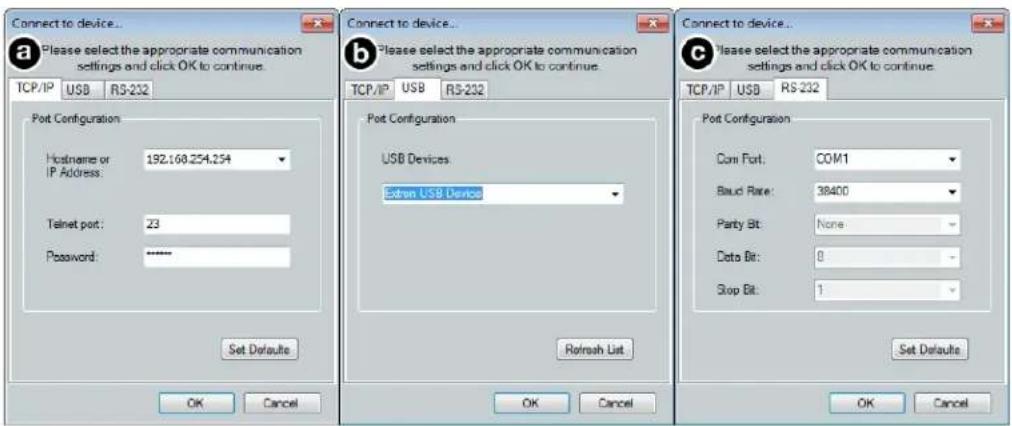
Figure 28. Connect to device... TCP/IP, USB, and RS-232 Dialog Box
- When a connection with a device is established, the Synchronize with Device dialog box opens.
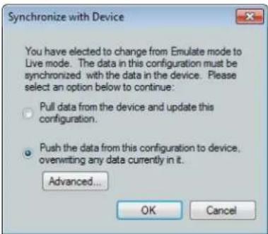
Figure 29. Synchronize with Device Dialog Box
a. Pull — Pulls the configuration file, presets, macros, and ACP configurations from the device and displays it in the DSP Configurator main workspace.
b. Push — Pushes the configuration file, presets, macros, and ACP configurations open in DSP Configurator to the connected DMP 128 Plus. This will overwrite any configuration currently on the device.
Click Advanced... to open the Advanced Push Options dialog box (see figure 30).
NOTE: If only pushing selected presets, the preset selection dialog box opens after clicking OK on the Advanced Push Options dialog box.
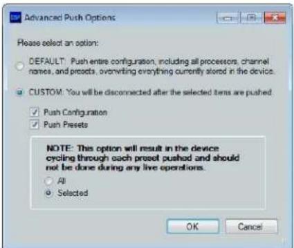
Figure 30. Advanced Push Options Dialog Box
If only pushing selected presets, mark them from the dialog box shown in figure 31 below.
![DSP Configurator Select the presets you would like to push to the device. Presets in the Configuration 1. ConfRin1 2. Auditorium 3. Lecture Hall 4. Not Available 5. Not Available 6. Not Available 7. Not Available 8. Not Available 9. Not Available 10. Not Available 11. Not Available 12. Not Available 13. Not Available Presets in the Device 1. [unassigned] 2. [unassigned] 3. [unassigned] 4. [unassigned] 5. [unassigned] 6. [unassigned] 7. [unassigned] 8. [unassigned] 9. [unassigned] 10. [unassigned] 11. [unassigned] 12. [unassigned] 13. [unassigned] OK Cancel](/content/2026/05/792275/images/9e2637c64603e6e2624a09c09792bded3182583bb815961d050b4fb5da075ae4.jpg)
Figure 31. Preset Selection Dialog Box
- Once a push or pull is completed, the current state of the connected DMP 128 Plus is displayed in the DSP Configurator status panel and the device is ready for further configuration.
Exit Live Mode and Enter Emulate Mode
- Click the Emulate button in the DSP Configurator menu bar (see figure 32, ①). Alternatively, select Tools > Disconnect from Device or press
on the keyboard.
Figure 32. Emulate Button
- Click OK to confirm.
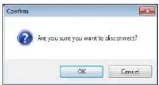
Figure 33. Confirm Disconnect
DSP Configurator Inputs
All available inputs are listed vertically along the left side of the DSP Configurator main workspace. The input groups can be expanded or collapsed by clicking the expand) or (collapse) buttons next to the input group names.
There are four types of inputs available:
- Mic/Line Inputs
• Virtual Returns on page 48
• Aux Inputs on page 43
• Expansion and AT Inputs on page 53
Mic/Line Inputs
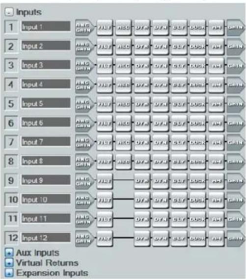
The twelve mic/line input channels on the DMP 128 Plus are shown in DSP Configurator under the Inputs panel (see figure 34).
flowchart
graph TD
    A["Input 1"] --> B["RAG GAIN"]
    C["Input 2"] --> D["RAG GAIN"]
    E["Input 3"] --> F["RAG GAIN"]
    G["Input 4"] --> H["RAG GAIN"]
    I["Input 5"] --> J["RAG GAIN"]
    K["Input 6"] --> L["RAG GAIN"]
    M["Input 7"] --> N["RAG GAIN"]
    O["Input 8"] --> P["RAG GAIN"]
    Q["Input 9"] --> R["RAG GAIN"]
    S["Input 10"] --> T["RAG GAIN"]
    U["Input 11"] --> V["RAG GAIN"]
    W["Input 12"] --> X["RAG GAIN"]

    B --> Y["7.5T"]
    D --> Z["7.5C"]
    D --> AA["7.5A"]
    D --> AB["7.5Y"]
    D --> AC["9.5T"]
    D --> AD["9.5X"]
    E --> AE["7.5T"]
    F --> AF["7.5C"]
    F --> AG["7.5A"]
    F --> AH["7.5Y"]
    F --> AI["9.5T"]
    F --> AJ["9.5X"]
    G --> AK["7.5T"]
    H --> AL["7.5C"]
    H --> AM["7.5A"]
    H --> AN["7.5Y"]
    H --> AO["9.5T"]
    H --> AP["9.5X"]
    I --> AQ["7.5T"]
    J --> AR["7.5C"]
    J --> AS["7.5A"]
    J --> AT["7.5Y"]
    J --> AU["9.5T"]
    J --> AV["9.5X"]
    K --> AW["7.5T"]
    L --> AX["7.5C"]
    L --> AY["7.5A"]
    L --> AZ["7.5Y"]
    L --> BA["9.5T"]
    L --> BB["9.5X"]
    M --> BC["7.5T"]
    N --> BD["7.5C"]
    N --> BE["7.5A"]
    N --> BF["7.5Y"]
    N --> BG["9.5T"]
    N --> BH["9.5X"]
    O --> BI["7.5T"]
    P --> BJ["7.5C"]
    P --> BK["7.5A"]
    P --> BL["7.5Y"]
    P --> BM["9.5T"]
    P --> BN["9.5X"]
    Q --> BO["7.5T"]
    R --> BP["7.5C"]
    R --> BQ["7.5A"]
    R --> BR["7.5Y"]
    R --> BS["9.5T"]
    R --> BT["9.5X"]
    S --> BU["7.5T"]
    T --> BV["7.5C"]
    T --> BW["7.5A"]
    T --> BX["7.5Y"]
    T --> BY["9.5T"]
    T --> BZ["9.5X"]
Figure 34. Inputs Panel
Inputs 1 - 8 offer AEC (Acoustic Echo Cancellation) DSP capability (C models only) and phantom power. Inputs 9 - 12 do not have AEC or phantom power. All inputs can receive mic level or line level signal, but inputs 1 - 8 are recommended for receiving microphone signal and inputs 9 - 12 are recommended for receiving line level signal.
Naming an Input Channel
- Click the input name field.

Figure 35. Input Name Field
- Highlight or delete the text and enter a new name.
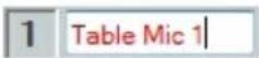
Figure 36. New Input Name
- Press
or navigate away from the field to confirm and apply the new input name. Press key to navigate to and highlight the next name field.
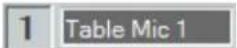
Figure 37. Renamed Input
NOTE: Follow the same procedure to edit an input name.
Input Building Blocks
Extron building blocks are a quick configuration tool that can significantly reduce configuration time. An input building block is a collection of processor and gain settings for an input processing chain. These building blocks have been designed by Extron based on extensive use and testing with each intended application or specific device.

flowchart
graph LR
    A["Input #1"] --> B["ANG"]
    B --> C["FILT"]
    C --> D["REC"]
    D --> E["DYN"]
    E --> F["DYN"]
    F --> G["OLY"]
    G --> H["DUCK"]
    H --> I["AM"]
    I --> J["GAIN"]
Figure 38. Accessing Input Building Blocks
Click the input number (see figure 38 above) to open the Building Blocks dialog box.
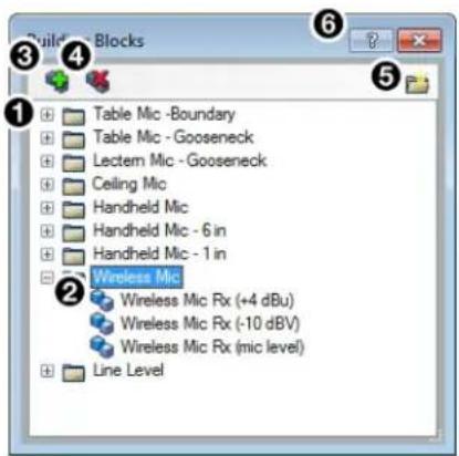
① Building Block Folders
④ Delete a Building Block Button
② General Building Blocks
⑤ New Folder Button
③ Add a Building Block Button
⑥ Building Blocks Help Button
Figure 39. Input Building Blocks Dialog Box
1 Building Block Folders — These folders group input types together, such as table or handheld mics, for easy access (see figure 40 below).
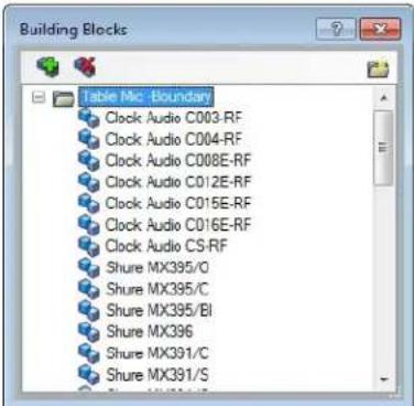
Figure 40. Mic Building Block Folder Contents
2 General Building Blocks — These building blocks provide quick setup for input sources. General building blocks provide a useful starting point for devices in the same product category as the name of the building block, such as handheld microphones, line level sources, and so on.
3 Add a Building Block Button — Creates a custom building block from the current gain and processor settings on the selected channel. When this button is clicked, the Add a Building Block dialog box opens. Name the new custom building block and choose a folder to save the block to, or create a new folder (see figure 41 below).
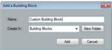
Figure 41. Add a Building Block Dialog Box
4 Delete a Building Block Button — Deletes the currently selected building block or building block folder. If default building blocks are deleted, they can be restored from the Organize Building Blocks dialog box. Custom building blocks can be saved to a file from the same dialog box (see Organize Building Blocks on page 88).
5 New Folder Button —Creates a new folder or sub-folder in the Building Blocks dialog box.
6 Building Blocks Help Button — Opens the Building Blocks topic of the DSP Configurator Help file. This topic contains more information on the different types of building blocks for inputs and outputs.
Input Processing
The mic/line input processing chain in DSP Configurator is visually represented by a string of blocks (see figure 42 below). Each block contains a specific processor or type of processor. For example, the Input Gain block contains a fader to boost or attenuate incoming signal, the Filter block contains several types of filters, and so on. Inputs 1 - 8 contain the following signal chain:
- Input Gain Block
- Input Filter Block
- Input AEC Block (C Models Only)
- Input Dynamics Blocks (2)
- Input Delay Block
- Input Ducking Block
- Input Automix Block
- Input Pre-Mixer Gain Block

flowchart
graph LR
    A["Input #1"] --> B["ANG GAIN"]
    B --> C["FILT"]
    C --> D["REC"]
    D --> E["DYN"]
    E --> F["DYN"]
    F --> G["DLY"]
    G --> H["DUCK"]
    H --> I["AM"]
    I --> J["GAIN"]
Figure 42. Input Processing Chain for Inputs 1 - 8
Inputs 9 - 12 do not contain AEC processing or phantom power. All other processors are available and function the same as inputs 1 - 8.

flowchart
graph LR
    A["9 Input #9"] --> B["ANG"]
    B --> C["FILT"]
    C --> D["DYN"]
    D --> E["DYN"]
    E --> F["ML"]
    F --> G["GAIN"]
Figure 43. Input Processing Chain for Inputs 9 - 12
Input Gain Block
Double-click the Input Gain block to open the Input Gain dialog box.

Figure 44. Input Gain Block
The Input Gain dialog box provides controls to configure the input gain stage of the input processing path.
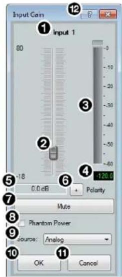
① Input Name
② Gain Fader
③ dBFS Meter
④ dBFS Numeric Readout
⑤ Input Gain Text Field
⑥ Polarity Toggle Button
⑦ Mute Button
⑧ Phantom Power Check Box
⑨ Source Drop-Down Menu
10 OK Button
⑪ Cancel Button
⑫ Input Gain Help Button
Figure 45. Input Gain Dialog Box
① Input Name — This name changes to match the default or user defined input name.
② Gain Fader — Provides up to 80 dB of gain or 18 dB of attenuation in 1 dB steps. Click the fader once and press the
③ dBFS Meter — This meter displays the input signal level in dBFS ranging from -60 dBFS to 0 dBFS. Once the signal reaches or passes -1 dBFS (default) or the clip threshold defined in the Options dialog box (see Options on page 93), the clip box located at the top of the meter lights red.
4 dBFS Numeric Readout — This read-only text box displays the numerical value of the input signal level in dBFS.
⑤ Input Gain Text Field — This text field allows the user to enter a gain or attenuation value in 0.1 dB steps.
⑥ Polarity Toggle Button — Inverts the signal polarity of the selected input. When the button displays the black + symbol on a gray field (☐), the polarity is normal. When the button displays the black - symbol on a yellow field (☐), the polarity is inverted.
⑦ Mute Button — Mutes signal at the input stage, preventing it from going any further in the signal processing chain.
⑧ Phantom Power Check Box — Provides 48 V phantom power to the selected input for use with condenser microphones. Available on inputs 1 through 8 only.
⑨ Source Drop-Down Menu (AT models only) — Selects the input audio source for the channel. Source options are analog (default) or any of the AT inputs. Input gain range changes to +24 dB to -18 dB when using AT inputs.
10 OK Button — Confirms changes and closes the Input Gain dialog box.
11 Cancel Button — Reverts any changes made to the contained parameters back to their states when the current instance of the Input Gain dialog box was opened and closes the dialog box.
12 Input Gain Help Button — Opens the Mic/Line Input Gain topic in the DSP Configurator Help file for further assistance in configuring input gain.
Input Filter Block
Double-click the Filter block to open the filter drop-down menu. Select one of the eleven available filters to insert into the block.
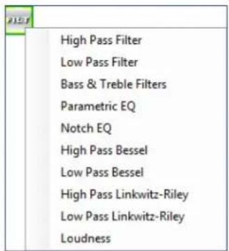
Figure 46. Filter Block and Drop-Down Menu
Alternatively, right-click the Filter block and select Insert, then select a filter to insert it into the block.
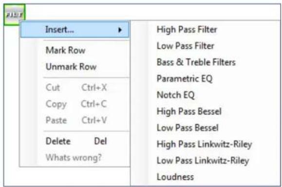
Figure 47. Insert Filter Drop-Down Menu
Once an initial filter is selected, the Filter block changes to display the type of filter applied. For example, if High Pass Filter is selected, the Filter block would display HIGH PASS instead of FILT. If multiple filters are applied, the Filter block displays FILT over a dark green field.


Figure 48. Filter Block Icons
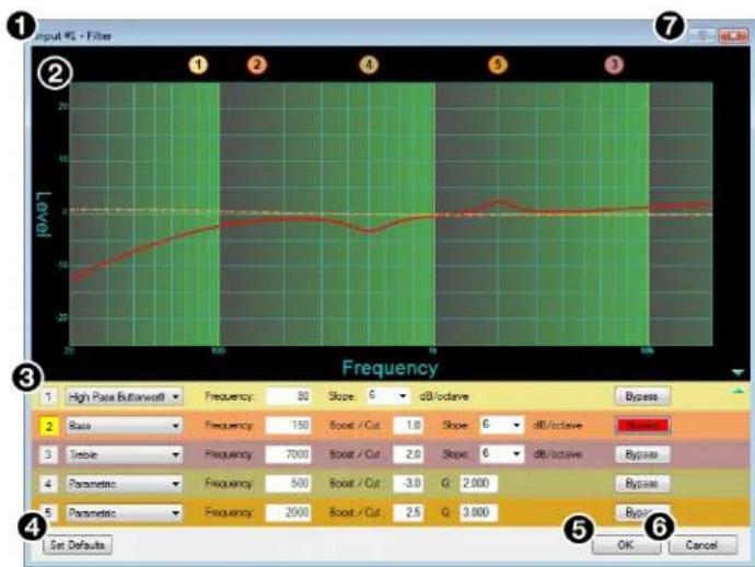
Once a filter is applied to the Filter block, double-click the block to open the Filter dialog box.
line
| Parameter | Value | | --------- | ----- | | Frequency | 80 | | Base | 150 | | Treble | 700 | | Parametric | 500 | | Parametric | 2000 | | Slope / Cut | 1.0 | | Slope / Cut | 2.0 | | Slope / Cut | -3.0 | | Slope / Cut | 2.5 | | dB/octave | 6 | | dB/octave | 6 | | dB/octave | 6 | | G: 2.000 | 2.000 | | G: 3.000 | 3.000 |① Filter Channel Name
⑤ OK Button
② Filter Graph
⑥ Cancel Button
③ Filter List
⑦ Filters Help Button
④ Set Defaults Button
Figure 49. Filter Dialog Box
① Filter Channel Name — This name changes to match the default or user defined input name.
② Filter Graph — Graphically displays the applied filter curve and provides handles for adjusting filter parameters. Numbers along the top of the graph represent the filter curve of the corresponding slot in the filter list below the graph. The number appears over the center frequency of the filter.
If a filter is active (unbypassed), it appears as a solid red curve. If a filter is bypassed, it appears as a broken orange curve (such as the bass filter in slot 2).
NOTE: All filters are bypassed by default.
③ Filter List — Provides filter drop-down menus for all 5 available filter slots. Frequency, Slope, Boost/Cut, Q, and Bypass controls are also available in this list.
Available filters include:
• High Pass Butterworth • High Pass Linkwitz-Reily
- Low Pass Butterworth
- Low Pass Linkwitz-Reily
- Bass • High Pass Bessel
- Treble
- Low Pass Bessel
- Parametric
- Loudness
- Notch
NOTE: See the DSP Configurator Help file for more information on each of the filters. Click the Filters Help button to open the help file topic discussing filters.
4 Set Defaults Button — Resets all filter parameters of all filters in the filter list to their default values.
To reset a single filter to default parameters, right-click the filter number on the left side of the Filter dialog box, and select Set to Default (see figure 50 below).
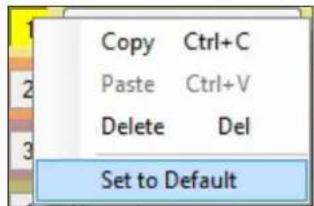
Figure 50. Set Single Filter Parameters to Default
5 OK Button — Confirms changes made to the contained parameters and closes the Filter dialog box.
⑥ Cancel Button — Reverts any changes made to the contained parameters back to their states when the current instance of the Filter dialog box was opened and closes the dialog box.
7 Filters Help Button — Opens the About Filters topic in the DSP Configurator Help file. This help file topic discusses each filter type in greater detail.
Input AEC Block (C Models Only)
About AEC
Echo occurs when audio from a talker in the far end is received and amplified into the near end listener's room, with that sound then being picked up by microphones in the near end acoustic space and sent back to the far end. The amount of signal sent back to the far end talker can be substantial, and with the added transmission delay, the result is an echo effect that can seriously compromise communication in a teleconference or videoconference.
The Extron Acoustic Echo Cancellation (AEC) processor removes the potential echo signal at the near end mic channel by comparing it to the received signal from the far end, designated as the “reference,” and then creating an adaptive filter to cancel the potential echo before it is sent back to the far end.
Successful operation of the AEC processing block is mainly a function of proper gain structure and selection of an AEC reference. This section provides an overview of those two elements.
Proper gain structure involves the relationship between the signal at the selected reference and the signal at the mic input, within the context of proper levels for the reference and mic inputs independently. The mic input gain setting will naturally be optimized for the voice level of the talker in that room. Therefore, the amount of signal from the far end picked up by the mic is dependent on how much far end signal is being amplified in the near end room and the distance from the mic to the speakers.
AEC Operation
Double-click the AEC block to open the AEC drop-down menu. Select AEC to insert the AEC processor.
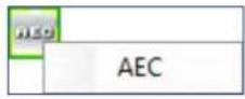
Figure 51. AEC Block and Drop-Down Menu
NOTE: Insert the AEC processor on the input with the near end microphone connected.
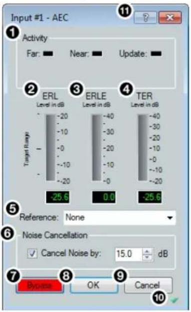
Once the AEC processor is inserted, double-click the AEC block to open the AEC dialog box.
① Activity Panel
② ERL Meter
③ ERLE Meter
4 TER Meter
⑤ Reference Selection Drop-Down
⑥ Noise Cancellation Panel
Figure 52. AEC Dialog Box
⑦ Bypass Button
8 OK Button
⑨ Cancel Button
10 Show/Hide Advanced Options Button
11 AEC Help Button
Activity Panel — Far lights when signal activity is detected from the far end. Near lights when activity is detected from the near end. Update lights when AEC is updating, converging, or reconverging.
② ERL Meter — ERL (echo return loss) is the ratio of the far end signal at the reference input to the far end signal received at the mic input and is expressed in dB. This meter should read between -10 dB and +10 dB for proper AEC operation.
3 ERLE Meter — ERLE (echo return loss enhancement) is the amount of potential echo signal that the AEC algorithm is cancelling (not including NLP processing) and is expressed in dB.
4 TER Meter — TER (total echo reduction) is the sum of ERL and ERLE and represents the total amount of echo reduction and is expressed in dB.
5 Reference Selection Drop-Down Menu — Provides all mic/line inputs, Aux inputs, virtual returns, line outputs, and Expansion outputs for reference selection. When a channel is selected as the reference, the AEC processor compares the reference channel signal to the current input channel.
6 Noise Cancellation Panel — Provides a checkbox to engage the noise canceller (engaged by default) and text field to enter the amount of noise reduction in dB.
⑦ Bypass Button — Bypasses the AEC processor. When the button is red, bypass is enabled.
8 OK Button — Confirms changes made to the contained parameters and closes the AEC dialog box.
9 Cancel Button — Reverts any changes made to the contained parameters back to their states when the current instance of the AEC dialog box was opened and closes the dialog box.
10 Show/Hide Advanced Options Button — Shows or hides the advanced configuration options for the AEC processor (see AEC Advanced Options on the next page).
11 AEC Help Button — Opens the Acoustic Echo Cancellation topic of the DSP Configurator Help file for further assistance in operating AEC processor.
AEC Advanced Options
The AEC dialog box provides advanced NLP (non-linear processing) options for fine tuning echo cancellation. These options are hidden by default. Click the Show/Hide Advanced Options button to access them (see figure 52, 10 on page 29).
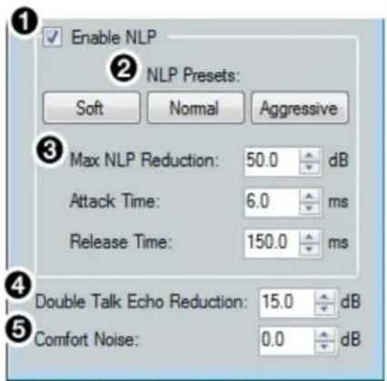
① Enable NLP Checkbox
② NLP Presets
③ NLP Reduction Parameters
④ Double Talk Echo Reduction
⑤ Comfort Noise
Figure 53. AEC Advanced Options
1 Enable NLP Checkbox — Checked by default, NLP (non-linear processing) is required to completely remove echo.
② NLP Presets — Offers three preset options for NLP parameters.
- Soft — Applies soft preset values to the NLP reduction parameters for light echo cancellation.
- Normal (default) — Applies normal preset values to the NLP reduction parameters for the widest array of echo cancellation needs.
- Aggressive — Applies aggressive preset values to the NLP reduction parameters for aggressive echo cancellation.
③ NLP Reduction Parameters — Provides text boxes for Max NLP Reduction, Attack Time, and Release Time to customize NLP reduction parameters.
4 Double Talk Echo Reduction — Provides a text box to enter a reduction value (in dB) when double talk occurs. Double talk is when near end talkers and far end talkers are speaking simultaneously while AEC is engaged.
⑤ Comfort Noise Text Box — Provides an ambient noise signal to prevent states of complete silence that may be perceived as a failed or dropped connection. 0 dB is the default.
Input Dynamics Blocks
Double-click the Dynamics block to open the dynamics drop-down menu.
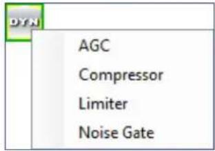
Figure 54. Dynamics Block and Drop-Down Menu
From the Dynamics drop-down menu, four types of dynamics processors are available. Select a dynamics processor type to insert it into the Dynamics block.
There are two Dynamics blocks available per mic/line input channel. Each block can be configured with any of the processor types.
The four types of dynamics processors available are:
• AGC (Automatic Gain Control) on the next page
• Compressor on page 34
- Limiter on page 35
- Noise Gate on page 36
Once a dynamics processor is inserted, double-click the dynamics block icon to open the corresponding dialog box.


Figure 55. AGC, Compressor, Limiter, and Noise Gate Icons
If a dynamics processor has been inserted and needs to be changed to a different dynamics processor, right-click the dynamics block, hover over Insert, and select a new processor to insert it (see figure 56 below).
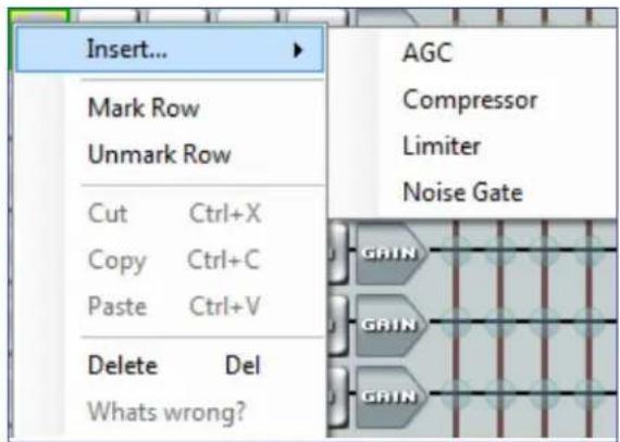
Figure 56. Changing Dynamics Processors
AGC (Automatic Gain Control)
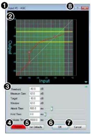
① Dynamics Channel Name
② AGC Graph
③ AGC Parameters List and Control
④ Bypass Button
⑤ Set Defaults Button
⑥ OK Button
⑦ Cancel Button
⑧ Dynamics Help Button
Figure 57. AGC Dialog Box
① Dynamics Channel Name — This name changes to match the default or user defined input name.
② AGC Graph — Graphically displays AGC parameter settings. Parameters can also be adjusted using this graph. Click and drag the yellow lines to adjust the Window parameter. Click and drag the bottom dot to adjust the Threshold parameter. Click and drag the middle dot to adjust the Maximum Gain parameter. Click and drag the top dot to adjust the Target parameter.
③ AGC Parameters List and Control — Provides text boxes to adjust all AGC parameters. Attack Time, Hold Time, and Release Time also have sliders that adjust their respective parameters. Click a slider once and use the
4 Bypass Button — Bypasses the AGC processor. When the button is red, bypass is enabled.
⑤ Set Defaults Button — Resets all AGC parameters to their default values. To view individual parameter default values, see the DSP Configurator Help file by clicking the Dynamics Help button (⑧) and opening the About Dynamics topic.
⑥ OK Button — Confirms changes made to the contained parameters and closes the AGC dialog box.
⑦ Cancel Button — Reverts any changes made to the contained parameters back to their states when the current instance of the AGC dialog box was opened and closes the dialog box.
⑧ Dynamics Help Button — Opens the Dynamics Operation topic of the DSP Configurator Help file for further assistance in operating dynamics processors.
Compressor
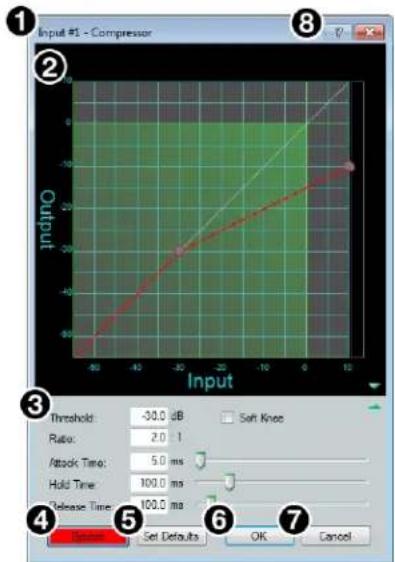
① Compressor Channel Name
② Compressor Graph
③ Compressor Parameter List and Control
④ Bypass Button
⑤ Set Defaults Button
⑥ OK Button
⑦ Cancel Button
⑧ Dynamics Help Button
Figure 58. Compressor Dialog Box
① Compressor Channel Name — This name changes to match the default or user defined input name.
② Compressor Graph — Graphically displays compressor parameter settings. Parameters can also be adjusted using this graph. Click and drag the dot within the green area of the graph to adjust the compressor Threshold. Click and drag the dot outside the green box to adjust the compressor Ratio.
③ Compressor Parameter List and Control — Lists all configurable parameters for the compressor. Text fields are available to adjust Threshold, Ratio, Attack Time, Hold Time, and Release Time. Click and drag sliders to adjust Attack Time, Hold Time, and Release Time. Click a slider once and use the
④ Bypass Button — Bypasses the compressor. When the button is red, bypass is enabled.
⑤ Set Defaults Button — Resets all compressor parameters to their default values. To view individual parameter default values, see the DSP Configurator Help file by clicking the Dynamics Help button (⑧) to open the About Dynamics topic.
⑥ OK Button — Confirms changes made to the contained parameters and closes the Compressor dialog box.
⑦ Cancel Button — Reverts any changes made to the contained parameters back to their states when the current instance of the Compressor dialog box was opened and closes the dialog box.
⑧ Dynamics Help Button — Opens the Dynamics Operation topic of the DSP Configurator Help file for further assistance in operating dynamics processors.
Limiter
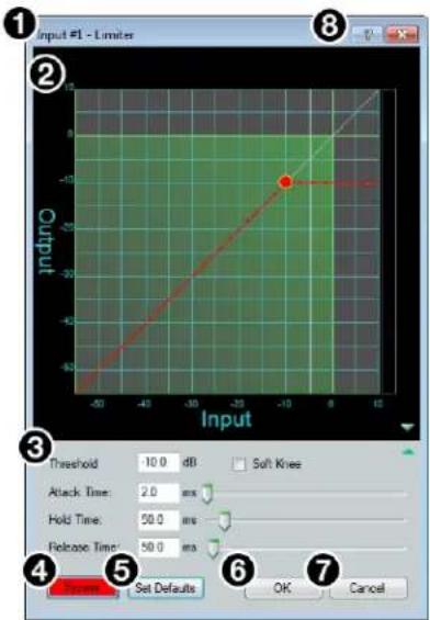
① Limiter Channel Name
② Limiter Graph
③ Limiter Parameter List and Control
④ Bypass Button
⑤ Set Defaults Button
⑥ OK Button
⑦ Cancel Button
⑧ Dynamics Help Button
Figure 59. Limiter Dialog Box
1 Limiter Channel Name — This name changes to match the default or user defined input name.
② Limiter Graph — Graphically displays limiter parameter settings. Parameters can also be adjusted using this graph. Click and drag the dot on the graph to adjust the limiter Threshold.
③ Limiter Parameter List and Control — Lists all configurable parameters for the limiter. Text fields are available to adjust Threshold, Attack Time, Hold Time, and Release Time. Click and drag sliders to adjust Attack Time, Hold Time, and Release Time. Click a slider once and use the
4 Bypass Button — Bypasses the limiter. When the button is red, bypass is enabled.
⑤ Set Defaults Button — Resets all limiter parameters to their default values. To view individual parameter default values, see the DSP Configurator Help file by clicking the Dynamics Help button (⑧) and navigate to the About Dynamics topic.
⑥ OK Button — Confirms changes made to the contained parameters and closes the Limiter dialog box.
⑦ Cancel Button — Reverts any changes made to the contained parameters back to their states when the current instance of the Limiter dialog box was opened and closes the dialog box.
8 Dynamics Help Button — Opens the Dynamics Operation topic of the DSP Configurator Help file for further assistance in operating dynamics processors.
Noise Gate
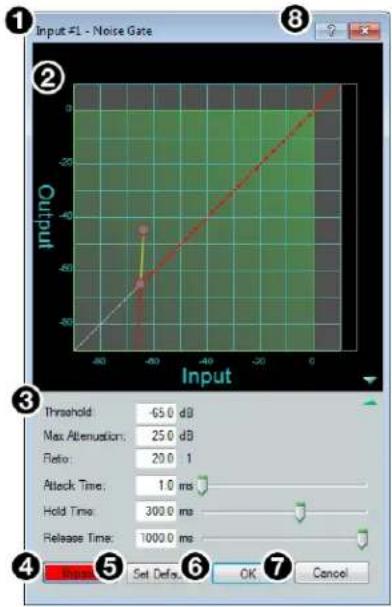
① Noise Gate Channel Name
② Noise Gate Graph
③ Noise Gate Parameter List and Control
④ Bypass Button
⑤ Set Defaults Button
⑥ OK Button
⑦ Cancel Button
⑧ Dynamics Help Button
Figure 60. Noise Gate Dialog Box
① Noise Gate Channel Name — This name changes to match the default or user defined input name.
② Noise Gate Graph — Graphically displays noise gate parameter settings. Parameters can also be adjusted using this graph. Click and drag the upper dot to adjust Ratio. Click and drag the middle dot to adjust Threshold. Click and drag the bottom dot (out of view at default settings) to adjust Max Attenuation.
③ Noise Gate Parameter List and Control — Lists all configurable parameters for the noise gate. Text fields are available to adjust Threshold, Max Attenuation, Ratio, Attack Time, Hold Time, and Release Time. Click and drag the sliders to adjust Attack Time, Hold Time, and Release Time. Click a slider once and use the
4 Bypass Button — Bypasses the noise gate. When the button is red, bypass is enabled.
⑤ Set Defaults Button — Resets all noise gate parameters to their default values. To view individual parameter default settings, see the DSP Configurator Help file by clicking the Dynamics Help button (⑧) and navigate to the About Dynamics topic.
⑥ OK Button — Confirms changes made to the contained parameters and closes the Noise Gate dialog box.
⑦ Cancel Button — Reverts any changes made to the contained parameters back to their states when the current instance of the Noise Gate dialog box was opened and closes the dialog box.
⑧ Dynamics Help Button — Opens the Dynamics Operation topic of the DSP Configurator Help file for further assistance in operating dynamics processors.
Input Delay Block
Double-click the Delay block to open the delay drop-down. Click Delay to insert the delay processor into the block.
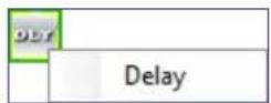
Figure 61. Delay Block and Drop-Down Menu
Once a delay processor is inserted into the Delay block, double-click the block to open the Delay dialog box.
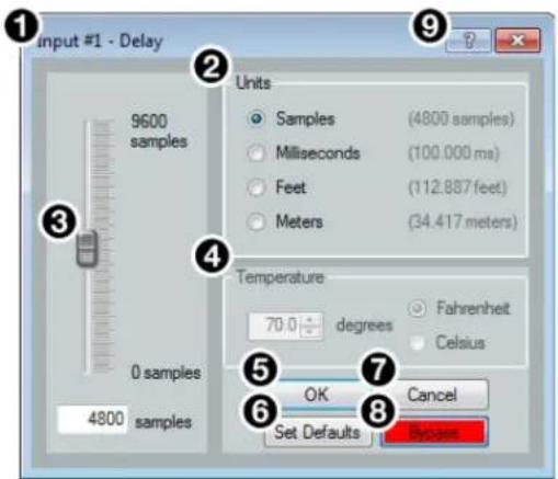
① Delay Channel Name
② Units of Measurement
③ Delay Fader and Text Box
④ Temperature Panel
⑤ OK Button
⑥ Set Defaults Button
⑦ Cancel Button
⑧ Bypass Button
⑨ Delay Help Button
Figure 62. Delay Dialog Box
① Delay Channel Name — This name changes to match the default or user defined input name.
② Units of Measurement — Radio buttons change the unit of measurement used by the delay fader and text box. Samples, Milliseconds, Feet, and Meters are available units of measurement. Values are converted when the unit of measurement is changed. Changing the unit of measurement does not alter the amount of delay applied to the signal.
③ Delay Fader and Text Box — Adjusts the amount of delay applied to the signal. Click and drag the fader up or down to increase or decrease the amount of delay. Click the fader once and use the
4 Temperature Panel — Becomes available when using delay in feet or meters. Compensates delay for ambient temperature in the acoustic space. Temperature is not available when using samples or milliseconds as the unit of measurement.
⑤ OK Button — Confirms changes made to the contained parameters and closes the Delay dialog box.
⑥ Set Defaults Button — Resets the delay to 4800 samples.
⑦ Cancel Button — Reverts any changes made to the contained parameters back to their states when the current instance of the Delay dialog box was opened and closes the dialog box.
⑧ Bypass Button — Bypasses the delay. When the button is red, bypass is enabled.
⑨ Delay Help Button — Opens the Delay Operation topic of the DSP Configurator Help file for further assistance in understanding operating the delay processor.
Input Ducking Block
The duck block contains a ducking processor as well as an adaptive gain processor.
- Ducker (see the next page) — Decreases levels on specified channels when signal is present above a set threshold on the duck source (trigger).
- Adaptive Gain (see page 40) — Increases levels on specified channels when signal is present above a set threshold on the adaptive gain source channel (trigger).
Double-click the Duck block to open the drop-down menu where the Ducker and Adaptive Gain processors can be selected.
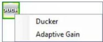
Figure 63. Duck Block and Drop-Down Menu
Select Ducker to insert a ducking processor into the duck block. Select Adaptive Gain to insert an adaptive gain processor into the duck block. Depending on the processor selected, the duck block displays DUCK for a ducker or AG for adaptive gain.

Figure 64. Ducking Block Icons
If a ducking processor has been inserted and needs to be changed to an adaptive gain processor, or vice versa, right-click the block and hover over Insert to insert a different processor (see figure 65 below).
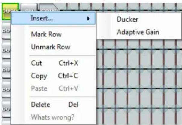
Figure 65. Changing Ducking Processor
Ducker
After inserting a ducker processor, double-click the Duck icon to open the Ducker Configuration dialog box.
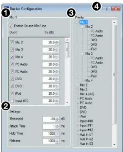
① Duck Source Configuration
② Duck Parameter Settings
③ Duck Priority Tree
④ Ducking Operation Help Button
Figure 66. Ducker Configuration Dialog Box
1 Duck Source Configuration — The Enable Source Mic/Line checkbox is checked when a ducker is inserted (default). In the Duck column, check the inputs that will be ducked. In the by (dB) column, enter the amount of ducking that will occur on each channel selected in the Duck column. When the threshold is exceeded on the duck source, ducking occurs on the selected channels.
② Duck Parameter Settings — Contains controls for setting Threshold, Attack Time, Hold Time, and Release. Click the Ducking Operation Help button (4) to open the Ducking Operation topic in the DSP Configurator Help fie.
3 Duck Priority Tree — Displays the ducking priority for all Input and Aux In channels. Select another input to populate the Ducker Configuration dialog with the ducker information for that channel. Channels with an adaptive gain processor are appended with an (AG) (see Mic 4 in figure 66 above). Channels with adaptive gain processors cannot be selected from this dialog box.
4 Ducking Operation Help Button — Opens the Ducking Operation topic of the DSP Configurator Help file for further assistance in ducker configuration.
Adaptive Gain
After inserting an adaptive gain processor, double-click the AG icon to open the Adaptive Gain dialog box.
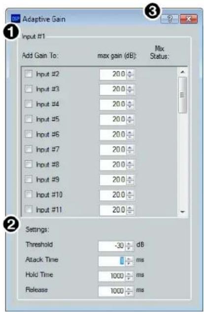
① Adaptive Gain Source Configuration
② Adaptive Gain Parameter Settings
③ Adaptive Gain Operation Help Button
Figure 67. Adaptive Gain Dialog Box
1 Adaptive Gain Source Configuration — In the Add Gain To column, check the inputs that will have gain added by the adaptive gain processor. In the Max Gain (dB) column, enter the maximum amount of gain that will be applied to each channel selected in the Add Gain To column. When a box is checked, gain is applied to that channel when signal exceeds the threshold on the adaptive gain trigger channel.
NOTE: For every 1 dB of signal beyond the level set in the Threshold field, 1 dB of gain will be added to the channels selected in the Add Gain To column. This occurs until the maximum gain set in the Max Gain (dB) field has been applied.
② Adaptive Gain Parameter Settings — Contains controls for Threshold, Attack Time, Hold Time, and Release Time.
③ Adaptive Gain Operation Help Button — Opens the Adaptive Gain Operation topic of the DSP Configurator Help file for further assistance in adaptive gain configuration.
Input Automix Block
Double-click the Automix block to open a drop-down menu. Select Auto-mixer to insert the automix processor into the block.
Figure 68. Automix Block and Drop-Down
Once the automix processor is inserted into the Automix block, double-click the block to open the Automix dialog box.
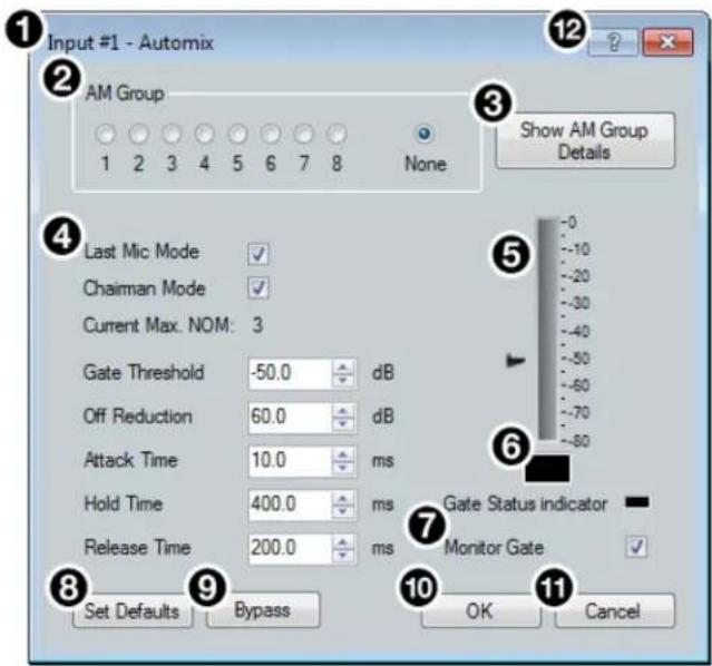
① Automix Channel Name
② AM Group Assignment Panel
③ Show AM Group Details Button
④ Automix Parameters
⑤ dBFS Meter
⑥ Gate Status Indicator
⑦ Monitor Gate Checkbox
⑧ Set Defaults Button
⑨ Bypass Button
10 OK Button
⑪ Cancel Button
⑫ Automix Help Button
Figure 69. Automix Dialog Box
1 Automix Channel Name — This name changes to match the default or user defined input name.
② AM Group Assignment Panel — Provides nine radio buttons to assign the current automix processor to an AM (automix) group. The default is None and leaves the automixer unassigned.
③ Show AM Group Details Button — Opens the Automix Groups dialog box (click the Automix Help button for more information regarding Automix Groups).
4 Automix Parameters — Provides configuration controls for all automix parameters.
⑤ dBFS Meter — Displays the post-automix signal level.
⑥ Gate Status Indicator — This LED lights when monitoring is enabled and the gate is open.
⑦ Monitor Gate Checkbox — Click the Monitor Gate checkbox to enable SIS responses regarding gate status (see Automixer Gate Monitoring on the next page).
⑧ Set Defaults Button — Resets all automix parameters to their default settings.
⑨ Bypass Button — Bypasses the automix processor. When the button is red, bypass is enabled.
10 OK Button — Confirms changes made to the contained parameters and closes the Automix dialog box.
11 Cancel Button — Reverts any changes made to the contained parameters back to their states when the Automix dialog box was opened and closes the dialog box.
12 Automix Help Button — Opens the Automix topic of the DSP Configurator Help file for further assistance in configuring the automix processor.
Automixer Gate Monitoring
Automixer gate monitoring allows the user to track when an automixer gate opens or closes. This feature can be enabled by checking the Monitor Gate checkbox in an Automix dialog (see figure 69, ⑦ on the previous page). When automixer gate monitoring is enabled for a channel, an unsolicited message is sent when the gate has opened or closed. The response will include the Automixer OID, gate open or closed status, and the signal level immediately after the status has changed (see the Automixer Gate Monitoring commands on page 146 for SIS response syntax).
Comparing the automixer gate threshold setting to the gate status in the response will indicate whether the automixer gate has opened or closed. When the gate status in the response is 1024 or greater, the gate has opened, and when the gate status in the response is less than 1024, the gate has closed.
Input Pre-Mixer Gain Block
Double-click the pre-mixer Gain block to open the Pre-mixer Gain dialog box.

Figure 70. Input Pre-mixer Gain Block
The Pre-mixer Gain dialog box provides controls to boost, attenuate, and mute the signal after input processing occurs and before it is sent to the mix matrix.
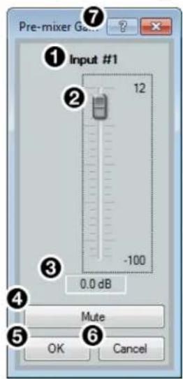
① Input Name
② Pre-mixer Gain Fader
③ Pre-mixer Gain Text Box
④ Mute Button
⑤ OK Button
⑥ Cancel Button
⑦ Pre-mixer Gain Help Button
Figure 71. Input Pre-mixer Gain Dialog Box
① Input Name — This name changes to match the default or user defined input name.
② Pre-mixer Gain Fader — Click and drag the gain fader to provide up to 12 dB of gain or 100 dB of attenuation in 1 dB steps. Click the fader and use the
③ Pre-mixer Gain Text Box — Enter a gain or attenuation value in 0.1 dB steps.
4 Mute Button — Mutes signal at the pre-mixer stage, preventing it from reaching the mix matrices.
⑤ OK Button — Confirms changes made to the contained parameters and closes the Pre-mixer Gain dialog box.
⑥ Cancel Button — Reverts any changes made to the contained parameters back to their states when the current instance of the Pre-mixer Gain dialog box was opened and closes the dialog box.
7 Pre-mixer Gain Help Button — Opens the Pre-mixer Gain topic of the DSP Configurator Help file for further assistance in understanding operating the Pre-mixer Gain dialog.
Aux Inputs
Eight Aux inputs are available with processing. These inputs can be assigned as one of the following:
- Player inputs that play audio files stored in the DMP 128 Plus internal memory (see Player Input on the next page)
- USB inputs that receive audio via the rear panel USB audio port (see USB Input on page 45)
• VoIP lines for use with a VoIP network (V models only, see VoIP Input on page 45)
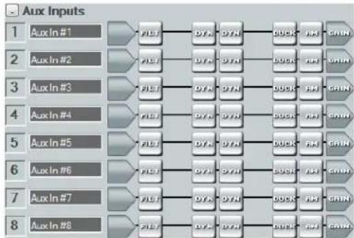
flowchart
graph LR
    A["Aux In #1"] --> B["FLST"]
    C["Aux In #2"] --> D["FLST"]
    E["Aux In #3"] --> F["FLST"]
    G["Aux In #4"] --> H["FLST"]
    I["Aux In #5"] --> J["FLST"]
    K["Aux In #6"] --> L["FLST"]
    M["Aux In #7"] --> N["FLST"]
    O["Aux In #8"] --> P["FLST"]
    B --> Q["DYN"]
    D --> R["DYN"]
    F --> S["DYN"]
    H --> T["DYN"]
    J --> U["DYN"]
    L --> V["DYN"]
    N --> W["DYN"]
    P --> X["DYN"]
    Q --> Y["BUCK"]
    R --> Z["BUCK"]
    S --> AA["BUCK"]
    T --> AB["BUCK"]
    U --> AC["BUCK"]
    V --> AD["BUCK"]
    W --> AE["BUCK"]
    X --> AF["BUCK"]
    Y --> AG["BUCK"]
    Z --> AH["BUCK"]
    AA --> AI["BUCK"]
    AB --> AJ["BUCK"]
    AC --> AK["BUCK"]
    AD --> AL["BUCK"]
    AE --> AM["BUCK"]
    AF --> AN["BUCK"]
    AG --> AO["BUCK"]
    AH --> AP["BUCK"]
    AI --> AQ["BUCK"]
    AJ --> AR["BUCK"]
    AK --> AS["BUCK"]
    AL --> AT["BUCK"]
    AM --> AU["BUCK"]
    AN --> AV["BUCK"]
    AO --> AW["BUCK"]
    AP --> AX["BUCK"]
    AQ --> AY["BUCK"]
    AR --> AZ["BUCK"]
    AS --> BA["BUCK"]
    AT --> BB["BUCK"]
    AU --> BC["BUCK"]
    AV --> BD["BUCK"]
    AW --> BE["BUCK"]
    AX --> BF["BUCK"]
    AY --> BG["BUCK"]
    AZ --> BH["BUCK"]
Figure 72. Aux Inputs Panel
Renaming an Aux Input
- Click the input name field.
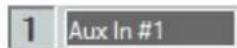
Figure 73. Aux Input Name Field
- Delete or highlight the text and type the desired name.
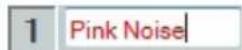
Figure 74. New Aux Input Name
- Press the
key or navigate away from the field to confirm and apply the new name. Press the key to navigate to and highlight the next name field.

Figure 75. Renamed Aux Input
NOTE: Follow the same procedure to edit an Aux input name.
Aux Input Building Blocks
Building blocks can be applied to all eight Aux input channels. These buildings blocks function the same as the mic/line input building blocks (see Input Building Blocks on page 22 for more information on configuring Aux input building blocks.
Aux Input Processing
The input processing chain in DSP Configurator is visually represented by a string of blocks. Each block contains a specific processor or type of processor. Aux Inputs 1 through 8 contain the following signal processing chain:
- Aux Input Gain Block
- Aux Input Filter Block
- Aux Input Dynamics Block (2)
- Aux Input Ducking Block
- Aux Input Automix Block
- Aux Input Pre-Mixer Gain Block
Aux Input Gain Block
By default, the Aux input gain block does not have an input source selected. Double-click the block to open the input selection drop-down, presenting three options for each Aux input source:
- Player — Plays audio files stored on the DMP 128 Plus internal memory.
- USB — Receives audio input from the rear panel USB port.
• VoIP (V models only) — Receives audio input from the VoIP network.
Player Input
Double-click the Aux input gain block and hover the mouse over Player... to display the eight available players. If no audio file is assigned to the player, the player displays [unassigned]. If an audio file is assigned to the player, the player displays the filename (see Players on page 75 for more information on configuring players). Select one of the players to insert it as the source for the selected Aux input.
![Player... USB... Player 1: [unassigned] Player 2: [unassigned] Player 3: [unassigned] Player 4: [unassigned] Player 5: [unassigned] Player 6: [unassigned] Player 7: [unassigned] Player 8: [unassigned]](/content/2026/05/792275/images/4dfa4c0b42611e66303e95529d07e871f2e1da1ee1a389528e4666ac4b681f98.jpg)
Figure 76. Aux Input Player Selection
Once a player is selected as an Aux input source, start and stop controls are available in Live mode by right clicking the input gain dialog and hovering over Player Control....
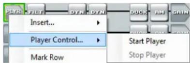
Figure 77. Player Start and Stop Controls
USB Input
Double-click the Aux input gain block and hover the mouse over USB... to display the four available USB audio channels. Select one of the USB channels to insert it as the source for the selected Aux input.
The four USB channels appear as two pairs of stereo channels:
- USB 1 left and right channels are for communications audio from a connected computer.
• USB 2 left and right channels are for playback audio from a connected computer.
The DMP 128 Plus appears both as a communications and as a playback audio device in the operating system of the host computer. Select the DMP 128 Plus as the output device for both communication audio and playback audio to route audio from the host computer to the DMP 128 Plus via the rear panel USB audio port.
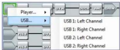
Figure 78. Aux Input USB Selection
VoIP Input
Double-click the Aux input gain block and hover the mouse over VoIP... to display the eight available VoIP lines. Select one of the VoIP lines to insert it as the source for the selected Aux input. Aux inputs with VoIP lines selected as the source receive signal via the far end of the VoIP network. VoIP lines can be assigned to Aux channels before the line is registered with the call server; however, VoIP lines must be registered with a call server and configured from the DMP 128 Plus VoIP web page before these inputs can function properly (see DMP 128 Plus VoIP Web Page on page 167). Multiple appearances of a single line can be placed on multiple Aux inputs for conference calling capabilities.
NOTE: When a VoIP line is assigned as the source or removed from Aux input, the same VoIP line is assigned to or removed from the corresponding Aux output.
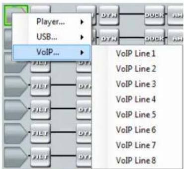
Figure 79. Aux Input VoIP Line Selection
Aux Input Dialog Box
Once a source has been selected for an Aux input, double-click the Aux input gain block to open the Aux Input dialog box.
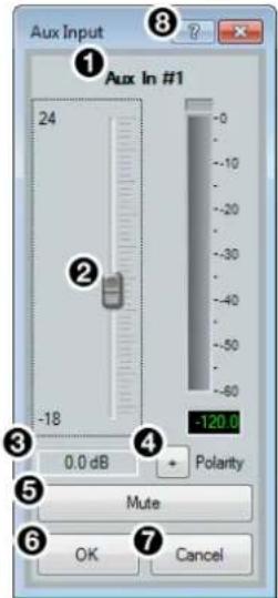
① Aux Input Name
② Aux Input Gain Fader
③ Aux Input Gain Text Box
④ Polarity Button
⑤ Mute Button
⑥ OK Button
⑦ Cancel Button
⑧ Aux Input Help Button
Figure 80. Aux Input Gain Dialog Box
① Input Name — This name changes to match the default or user defined Aux input name.
② Aux Input Gain Fader — Click and drag the gain fader to provide up to 24 dB of gain or 18 dB of attenuation in 1 dB steps. Click the fader and use the
③ Aux Input Gain Text Box — Enter a gain or attenuation value in 0.1 dB steps.
4 Polarity Button — Click this button to invert the signal polarity of the selected Aux input. When the button displays the black + symbol on a gray field (☐), the polarity is normal. When the button displays the black - symbol on a yellow field (☐), the polarity is inverted.
⑤ Mute Button — Mutes signal at the Aux input stage, preventing it from going any further in the signal processing chain.
⑥ OK Button — Confirms changes made to the contained parameters and closes the Aux Input dialog box.
⑦ Cancel Button — Reverts any changes made to the contained parameters back to their states when the current instance of the Aux Input dialog box was opened and closes the dialog box.
⑧ Aux Input Help Button — Opens the Aux Input topic of the DSP Configurator Help file for further assistance in configuring Aux input sources.
Aux Input Filter Block
One filter block is available for each Aux input channel. This filter block functions the same as the mic/line input filter block (see Input Filter Block on page 26 for information on configuring the Aux input filter block).
Aux Input Dynamics Block
Two dynamics blocks are available for each Aux input. These blocks function the same as the mic/line input dynamics blocks (see Input Dynamics Blocks on page 32 for information on configuring the Aux input dynamics blocks).
Aux Input Ducking Block
One ducking block is available for each Aux input. This block functions the same as the mic/line input ducking block (see Input Ducking Block on page 38 for information on configuring the Aux input ducking block).
Aux Input Automix Block
One automix block is available for each Aux input. This block functions the same as the mic/line input automix block (see Input Automix Block on page 40 for information on configuring the Aux input automix block).
Aux Input Pre-Mixer Gain Block
The Aux input pre-mixer gain block functions the same as the mic/line input pre-mixer gain block (see Input Pre-Mixer Gain Block on page 42 for information on configuring the Aux input pre-mixer gain block).
Virtual Returns
Virtual returns receive signal when inputs are routed to the virtual send bus (see figure 93 on page 56). Sixteen virtual return channels are available and are labeled A through P. These channels can be used in a number of applications. For example, they can act as an AEC reference channel or be used for sub-mix processing.
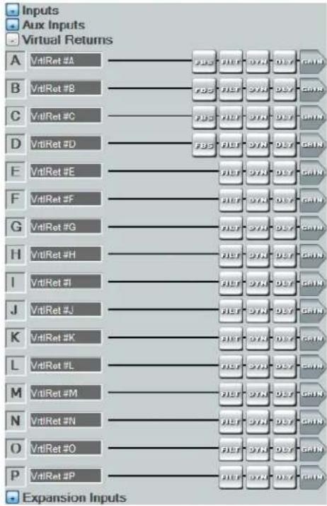
flowchart
graph TD
    A["VrtlRet #A"] --> FDS1["FDS"]
    B["VrtlRet #B"] --> FDS2["FDS"]
    C["VrtlRet #C"] --> FDS3["FDS"]
    D["VrtlRet #D"] --> FDS4["FDS"]
    E["VrtlRet #E"] --> FDS5["FDS"]
    F["VrtlRet #F"] --> FDS6["FDS"]
    G["VrtlRet #G"] --> FDS7["FDS"]
    H["VrtlRet #H"] --> FDS8["FDS"]
    I["VrtlRet #I"] --> FDS9["FDS"]
    J["VrtlRet #J"] --> FDS10["FDS"]
    K["VrtlRet #K"] --> FDS11["FDS"]
    L["VrtlRet #L"] --> FDS12["FDS"]
    M["VrtlRet #M"] --> FDS13["FDS"]
    N["VrtlRet #N"] --> FDS14["FDS"]
    O["VrtlRet #O"] --> FDS15["FDS"]
    P["VrtlRet #P"] --> FDS16["FDS"]
    FDS1 --> GAIN1["GAIN"]
    FDS2 --> GAIN2["GAIN"]
    FDS3 --> GAIN3["GAIN"]
    FDS4 --> GAIN4["GAIN"]
    FDS5 --> GAIN5["GAIN"]
    FDS6 --> GAIN6["GAIN"]
    FDS7 --> GAIN7["GAIN"]
    FDS8 --> GAIN8["GAIN"]
    FDS9 --> GAIN9["GAIN"]
    FDS10 --> GAIN10["GAIN"]
    FDS11 --> GAIN11["GAIN"]
    FDS12 --> GAIN12["GAIN"]
    FDS13 --> GAIN13["GAIN"]
    FDS14 --> GAIN14["GAIN"]
    FDS15 --> GAIN15["GAIN"]
    FDS16 --> GAIN16["GAIN"]
    FDS17 --> GAIN17["GAIN"]
    FDS18 --> GAIN18["GAIN"]
    FDS19 --> GAIN19["GAIN"]
    FDS20 --> GAIN20["GAIN"]
    FDS21 --> GAIN21["GAIN"]
    FDS22 --> GAIN22["GAIN"]
    FDS23 --> GAIN23["GAIN"]
    FDS24 --> GAIN24["GAIN"]
    FDS25 --> GAIN25["GAIN"]
    FDS26 --> GAIN26["GAIN"]
    FDS27 --> GAIN27["GAIN"]
    FDS28 --> GAIN28["GAIN"]
    FDS29 --> GAIN29["GAIN"]
    FDS30 --> GAIN30["GAIN"]
    FDS31 --> GAIN31["GAIN"]
    FDS32 --> GAIN32["GAIN"]
    FDS33 --> GAIN33["GAIN"]
    FDS34 --> GAIN34["GAIN"]
    FDS35 --> GAIN35["GAIN"]
    FDS36 --> GAIN36["GAIN"]
    FDS37 --> GAIN37["GAIN"]
    FDS38 --> GAIN38["GAIN"]
    FDS39 --> GAIN39["GAIN"]
    FDS40 --> GAIN40["GAIN"]
Figure 81. Virtual Returns Input Panel
Renaming a Virtual Return
- Click the virtual return name field.

VrtiRet #A
Figure 82. Virtual Return Name Field
- Delete or highlight the text and type the desired name.

AEC Ref
Figure 83. New Virtual Return Name
- Press the
key or navigate away from the field to confirm and apply the new name. Press the key to navigate to and highlight the next name field.

AEC Ref
Figure 84. Renamed Virtual Return
NOTE: Follow the same procedure to edit a Virtual Return name.
Virtual Return Building Blocks
Building blocks can be applied to all 16 virtual return channels (see Input Building Blocks on page 22 for more information on configuring virtual return building blocks).
Virtual Return Processing
Virtual returns A through D contain the following signal processing chain:
- Virtual Return Feedback Suppressor Block
- Virtual Return Filter Block
- Virtual Return Dynamics Block
- Virtual Return Delay Block
- Virtual Return Pre-Mixer Gain Block
Virtual returns E through P contain the following signal processing chain:
- Virtual Return Filter Block
- Virtual Return Dynamics Block
- Virtual Return Delay Block
- Virtual Return Pre-Mixer Gain Block
NOTE: Only Virtual Return channels A through D contain Feedback Suppression processing blocks.
Virtual Return Feedback Suppressor Block
Use the feedback suppressor when there is an indication of feedback during live operation. Dynamic filters automatically detect feedback on a live mic channel, and engage a set of up to 5 fixed and 15 dynamic filters to counteract feedback at the detected frequencies. The dynamic filters act in a “first in, first out” rotation. If all 15 dynamic filters are employed and an additional feedback frequency is detected, the first feedback frequency detected is overwritten.
To avoid a new feedback frequency overwriting a previously detected frequency, up to 5 dynamic filters can be transferred into fixed filters. Once a dynamic filter is transferred into a fixed filter, it can only be overwritten by manually assigning a new frequency to the filter.
Double-click the feedback suppressor block to show the feedback suppressor drop-down menu. Select Feedback Suppressor to insert a feedback suppressor processor into the signal chain.

Feedback Suppressor
Figure 85. Feedback Suppressor Block and Drop-Down Menu
After inserting the feedback suppressor in the signal chain, double-click the FBS block to open the Feedback Suppressor dialog box.
Feedback Suppressor Dialog Box
The Feedback Suppressor dialog box contains three tabs for configuring feedback suppression.
- Settings Tab on the next page
• Dynamic Filters Tab on page 51
• Fixed Filters Tab on page 52
Settings Tab
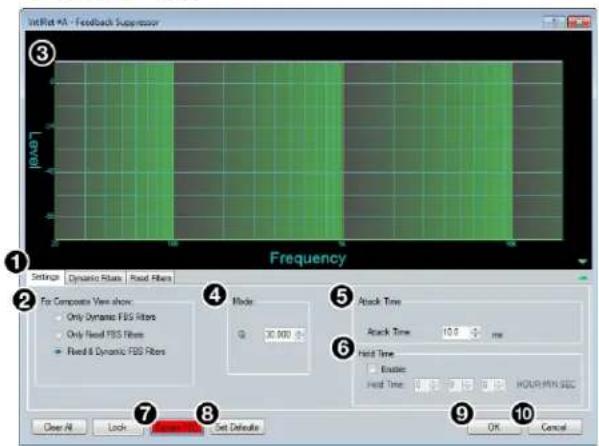
① Settings Tab
② Composite View Panel
③ Filter Graph
④ Q Adjustment Panel
⑤ Attack Time Panel
⑥ Hold Time Panel
⑦ Bypass FBS Button
⑧ Set Defaults Button
⑨ OK Button
10 Cancel Button
Figure 86. Feedback Suppressor Dialog Box - Settings Tab
① Settings Tab — Provides access to the global FBS settings.
② Composite View Panel — Three radio buttons control which filters are displayed in the filter graph:
• Only Dynamic FBS Filters
• Only Fixed FBS Filters
• Fixed & Dynamic FBS Filters (default)
③ Filter Graph — Displays the dynamic filters, fixed filters, or both, as selected in the Composite View panel.
④ Q Adjustment Panel — Adjust the default Q parameter of the dynamic filters using the text box or the up/down spinner controls.
⑤ Attack Time Panel — Adjust the default Attack Time for dynamic filters.
⑥ Hold Time Panel — Provides an Enable checkbox, that enables the Hold Time parameter. Entering a time into the Hold Time text boxes sets how long each dynamic filter will hold before removing the filter.
⑦ Bypass FBS — Turns off feedback detection when bypass is engaged (button is red when bypass is engaged). Only the dynamic filters are bypassed. Fixed filters remain active.
⑧ Set Defaults Button — Resets parameters on all tabs to their default values and positions.
⑨ OK Button — Confirms changes made to the contained parameters and closes the Feedback Suppressor dialog box.
10 Cancel Button — Reverts any changes made to the contained parameters back to their states when the current instance of the Feedback Suppressor dialog box was opened and closes the dialog box.
Dynamic Filters Tab
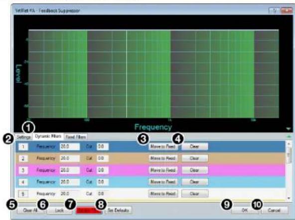
① Dynamic Filters Tab
② Dynamic Filters List
③ Move to Fixed Button
④ Clear Button
⑤ Clear All Button
⑥ Lock Button
⑦ Bypass FBS
⑧ Set Defaults Button
⑨ OK Button
10 Cancel Button
Figure 87. Feedback Suppressor Dialog Box - Dynamic Filters Tab
① Dynamic Filters Tab — Provides access to dynamic filter configuration options.
② Dynamic Filters List — Displays a list of 15 dynamic feedback suppression filters. As feedback is detected on the virtual return channel, dynamic filters are applied to suppress feedback with the Q parameter defined in the Settings tab.
③ Move to Fixed Button — Transfers the dynamic filter along with its current parameters to the Fixed Filters tab, allowing parameters to be edited. This frees up a filter slot in the Dynamic Filters list.
④ Clear Button — Clears the dynamic filter and contained parameters.
⑤ Clear All Button — Clears all dynamic filters and resets the feedback detection and suppression process.
⑥ Lock Button — Locks current dynamic filters and prevents more dynamic filters from being applied.
⑦ Bypass FBS Button — Bypasses the FBS processor. When the button is red, FBS is bypassed.
⑧ Set Defaults Button — Resets parameters on all tabs to their default values and positions.
⑨ OK Button — Confirms changes made to the contained parameters and closes the Feedback Suppressor dialog box.
10 Cancel Button — Reverts any changes made to the contained parameters back to their states when the current instance of the Feedback Suppressor dialog box was opened and closes the dialog box.
Fixed Filters Tab
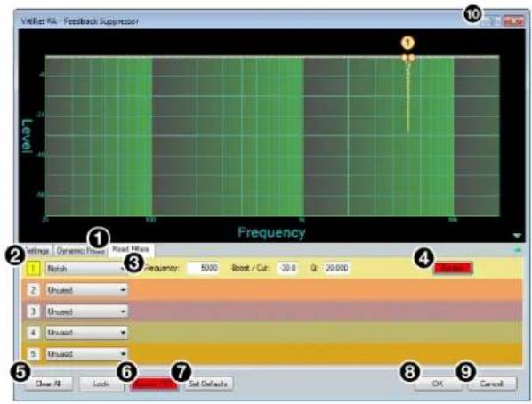
① Fixed Filters Tab
② Fixed Filters List
③ Filter Parameters
④ Single Filter Bypass Button
⑤ Clear All Button
⑥ Bypass FBS Button
⑦ Set Defaults Button
⑧ OK Button
⑨ Cancel Button
10 Feedback Suppressor Help Button
Figure 88. Feedback Suppressor Dialog Box - Fixed Filters Tab
① Fixed Filters Tab — Provides access to fixed filter configuration options.
② Fixed Filters List — Displays up to 5 fixed feedback suppression filters.
③ Filter Parameters — Configure the Frequency, Boost/Cut, and Q parameters for each fixed filter using the text boxes.
4 Single Filter Bypass Button — Bypasses only the filter associated with that filter slot. When the button is red, the filter is bypassed.
⑤ Clear All Button — Clears all fixed filters from the list.
⑥ Bypass FBS Button — Bypasses the FBS processor. When the button is red, FBS is bypassed.
⑦ Set Defaults Button — Resets parameters on all tabs to their default values and positions.
⑧ OK Button — Confirms changes made to the contained parameters and closes the Feedback Suppressor dialog box.
⑨ Cancel Button — Reverts any changes made to the contained parameters back to their states when the current instance of the Feedback Suppressor dialog box was opened and closes the dialog box.
10 Feedback Suppressor Help Button — Opens the Feedback Suppressor topic of the DSP Configurator Help file for further assistance in understanding and operating the feedback suppression processor.
Virtual Return Filter Block
One filter block is available for each virtual return channel. This filter block functions the same as the mic/line input filter block (see Input Filter Block on page 26 for information on configuring the virtual return filter block).
Virtual Return Dynamics Block
One dynamics block is available for each virtual return channel. This block functions the same as the mic/line input dynamics block (see Input Dynamics Blocks on page 32 for information on configuring the virtual return dynamics block).
Virtual Return Delay Block
One delay block is available for each virtual return channel. This block functions the same as the mic/line input delay block (see Input Delay Block on page 37 for information on configuring the virtual return delay block).
Virtual Return Pre-Mixer Gain Block
The virtual return pre-mixer gain block functions the same as the mic/line input pre-mixer gain block (see Input Pre-Mixer Gain Block on page 42 for information on configuring the virtual return pre-mixer gain block).
Expansion and AT Inputs
The expansion inputs receive signal via the rear panel EXP port when connected with another EXP enabled device. AT inputs receive signal from the Dante network when connected to an audio network (AT models only). The DMP 128 Plus can receive 16 channels of audio via the EXP port and 48 channels of audio via Dante (AT models only). On a DMP 128 Plus AT model, AT inputs 33 through 48 can be used for the EXP inputs allowing use of the Dante network and the EXP port simultaneously (see Expansion Bus on page 94).
Renaming an Expansion or AT Input
NOTES:
- AT inputs only appear on DMP 128 Plus AT models.
- AT inputs can only be renamed when connected in Live mode. Default input names appear in Emulate mode.
-
Renaming an AT input in DSP Configurator affects the receiver name in Dante Controller. Alternatively, renaming a receiver channel name in Dante Controller affects the name displayed in DSP Configurator (see Renaming a Receiver or Transmitter on page 113).
-
Click the expansion or AT input name field.
1 Exp #1
Figure 89. Expansion Input Name Field
- Delete or highlight the text and type the desired name.
1 Rack 1 DMP 2
Figure 90. New Expansion Input Name
- Press the
key or navigate away from the field to confirm and apply the new name. Press the key to navigate to and highlight the next name field.
1 Rack 1 DMP 2
Figure 91. Renamed Expansion
NOTE: Follow the same procedure to edit an Expansion Input name.
Expansion and AT Inputs Overview
With the Extron Expansion Port (EXP), two EXP enabled devices can be connected for bidirectional communication of 16 audio channels. When two units are connected, one unit must be set as the Primary Unit and the other must be set as the Secondary Unit (see Expansion Bus on page 94). This synchronizes the sampling clocks of the two units.
AT inputs allow a DMP 128 Plus AT model to receive signal from the audio network. Network audio routing is done with Dante Controller (see Dante Controller on page 107).
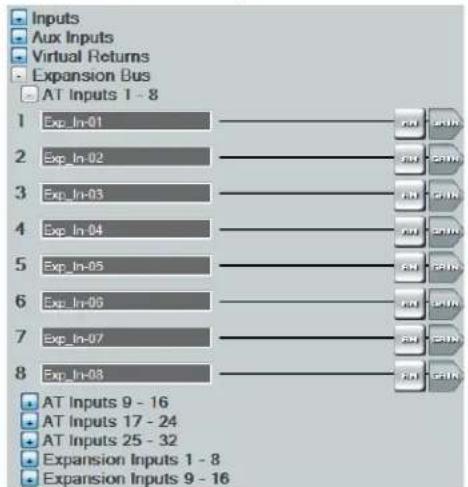
flowchart
graph TD
    A["1 Exp_In-01"] --> B["AT"]
    C["2 Exp_In-02"] --> D["AT"]
    E["3 Exp_In-03"] --> F["AT"]
    G["4 Exp_In-04"] --> H["AT"]
    I["5 Exp_In-05"] --> J["AT"]
    K["6 Exp_In-06"] --> L["AT"]
    M["7 Exp_In-07"] --> N["AT"]
    O["8 Exp_In-08"] --> P["AT"]
    Q["AT Inputs 9 - 16"] --> R["AT Inputs 17 - 24"]
    S["AT Inputs 25 - 32"] --> T["Expansion Inputs 1 - 8"]
    U["Expansion Inputs 9 - 16"] --> V["Expansion Inputs 9 - 16"]
Figure 92. Expansion Bus Panel with AT and Expansion Inputs
Expansion and AT Inputs Processing
The expansion and AT inputs contain two processor blocks in their signal chain:
- Automix Block
- Pre-mixer Gain Block
Expansion and AT Input Automix Block
One automix block is available for each expansion and AT input. This block functions the same as the mic/line input automix block (see Input Automix Block on page 40 for information on configuring the EXP input automix block).
Expansion and AT Input Pre-Mixer Gain Block
The expansion and AT input pre-mixer gain block functions the same as the mic/line input pre-mixer gain block (see Input Pre-Mixer Gain Block on page 42 for information on configuring the virtual return pre-mixer gain block).
Mix-Points
DSP Configurator contains twelve mix matrices that connect all inputs and outputs (see figure 93 on the next page). The mix matrices set post-processing mix levels.
Each input is connected to a mix-point for the signal to be routed to an output. In general, mix levels are set relative to each other, achieving a blend of input signals at an optimal output level, close to, but not exceeding 0 dBFS at the output.
NOTE: In order for mix-points to appear in the workspace, the input group sending signal to the mix-point must be expanded and the input channel must be visible.
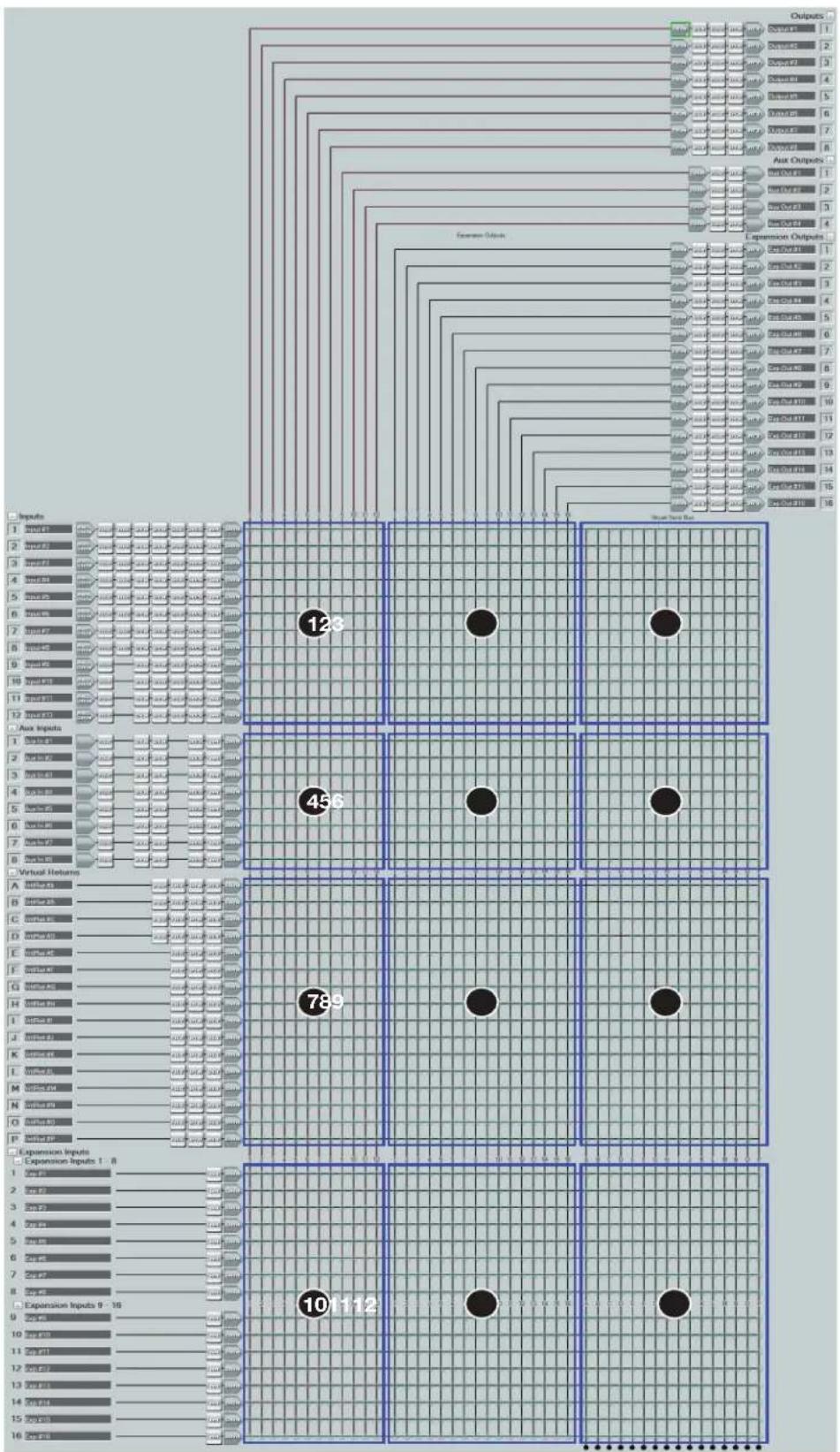
flowchart
graph TD
    A["Input 1: Input F1"] --> B["Array 1"]
    C["Input 2: Input F2"] --> D["Array 2"]
    E["Input 3: Input F3"] --> F["Array 3"]
    G["Input 4: Input F4"] --> H["Array 4"]
    I["Input 5: Input F5"] --> J["Array 5"]
    K["Input 6: Input F6"] --> L["Array 6"]
    M["Input 7: Input F7"] --> N["Array 7"]
    O["Input 8: Input F8"] --> P["Array 8"]
    Q["Input 9: Input F9"] --> R["Array 9"]
    S["Input 10: Input F10"] --> T["Array 10"]
    U["Input 11: Input F11"] --> V["Array 11"]
    W["Input 12: Input F12"] --> X["Array 12"]
    Y["Input 13: Input F13"] --> Z["Array 13"]
    AA["Input 14: Input F14"] --> AB["Array 14"]
    AC["Input 15: Input F15"] --> AD["Array 15"]
    AE["Input 16: Input F16"] --> AF["Array 16"]

    B --> AG["Output 1: Output F1"]
    D --> AH["Output 2: Output F2"]
    F --> AI["Output 3: Output F3"]
    H --> AJ["Output 4: Output F4"]
    J --> AK["Output 5: Output F5"]
    L --> AL["Output 6: Output F6"]
    M --> AM["Output 7: Output F7"]
    N --> AN["Output 8: Output F8"]
    O --> AO["Output 9: Output F9"]
    P --> AP["Output 10: Output F10"]
    Q --> AQ["Output 11: Output F11"]
    R --> AR["Output 12: Output F12"]

    AG --> AS["External Outputs"]
    AH --> AS
    AI --> AS
    AJ --> AS
    AK --> AS
    AL --> AS
    AM --> AS
    AN --> AS
    AO --> AS
    AP --> AS

    AS --> AT["Output 1: Output F1"]
    AS --> AU["Output 2: Output F2"]
    AS --> AV["Output 3: Output F3"]
    AS --> AW["Output 4: Output F4"]
    AS --> AX["Output 5: Output F5"]
    AS --> AY["Output 6: Output F6"]
    AS --> AZ["Output 7: Output F7"]
    AS --> BA["Output 8: Output F8"]
    AS --> BB["Output 9: Output F9"]
    AS --> BC["Output 10: Output F10"]
    AS --> BD["Output 11: Output F11"]
    AS --> BE["Output 12: Output F12"]

    AT --> BF["Output 1: Output F1"]
    AU --> BG["Output 2: Output F2"]
    AV --> BH["Output 3: Output F3"]
    AW --> BI["Output 4: Output F4"]
    AX --> BJ["Output 5: Output F5"]
    AY --> BK["Output 6: Output F6"]
    AZ --> BL["Output 7: Output F7"]

    AU --> BM["Output 8: Output F8"]
    AV --> BN["Output 9: Output F9"]

    AU --> BO["Output 9: Output F10"]

    AT --> BP["Output 9: Output F11"]

    AU --> BQ["Output B: Output F12"]

    AU --> BR["Output B: Output F13"]

    AU --> BS["Output B: Output F14"]

    AU --> BT["Output B: Output F15"]

    AU --> BU["Output B: Output F16"]

    AU --> BV["Output B: Output F17"]

    AU --> BW["Output B: Output F18"]

    AU --> BX["Output B: Output F19"]

    AU --> BY["Output B: Output F20"]

    AU --> BZ["Output B: Output F21"]

    AU --> CA["Output B: Output F22"]

    AU --> CB["Output B: Output F23"]

    AU --> CC["Output B: Output F24"]

    AU --> CD["Output B: Output F25"]

    AU --> CE["Output B: Output F26"]

    AU --> CF["Output B: Output F27"]

    AU --> CG["Output B: Output F28"]

    AU --> CH["Output B: Output F29"]

    AU --> CI["Output B: Output F30"]

    AU --> CJ["Output B: Output F31"]

    AU --> CK["Output B: Output F32"]

    AU --> CL["Output B: Output F33"]

    AU --> CM["Output B: Output F34"]

    AU --> CN["Output B: Output F35"]

    AU --> CO["Output B: Output F36"]

    AU --> CP["Output B: Output F37"]

    AU --> CQ["Output B: Output F38"]

    AU --> CR["Output B: Output F39"]

    AU --> CS["Output B: Output F40"]

    AU --> CT["Output B: Output F41"]

    AU --> CU["Output B: Output F42"]

    AU --> CV["Output B: Output F43"]

    AU --> CW["Output B: Output F44"]

    AU --> CX["Output B: Output F45"]

    AU --> CY["Output B: Output F46"]

    AU --> CZ["Output B: Output F47"]

    AU --> DA["Output B: Output F48"]

    AU --> DB["Output B: Output F49"]

    AU --> DC["Output B: Output F50"]

    AU --> DD["Output B: Output F51"]

    AU --> DE["Output B: Output F52"]

    AU --> DF["Output B: Output F53"]

    AU --> DG["Output B: Output F54"]

    AU --> DH["Output B: Output F55"]

    AU --> DI["Output B: Output F56"]

    AU --> DJ["Output B: Output F57"]

    AU --> DK["Output B: Output F58"]

    AU --> DL["Output B: Output F59"]

    AU --> DV["Output B: Output F60"]

    AU --> DW["Output B: Output F61"]

    AU --> DX["Output B: Output F62"]

    AU --> DX
</details>
Figure 93. DSP Configurator Mix Matrices
① Mic/Line Inputs to Line and Aux Outputs
② Mic/Line Inputs to EXP Outputs
③ Mic/Line Inputs to Virtual Sends
④ Aux Inputs to Line and Aux Outputs
⑤ Aux Inputs to EXP Outputs
⑥ Aux Inputs to Virtual Sends
⑦ Virtual Returns to Line and Aux Outputs
⑧ Virtual Returns to EXP Outputs
⑨ Virtual Returns to Virtual Sends
⑩ EXP Inputs to Line and Aux Outputs
⑪ EXP Inputs to EXP Outputs
⑫ EXP Inputs to Virtual Sends
<h1 id="mix-point-dialog-box">Mix-Point Dialog Box</h1>
Double-click a mix-point to open the Mix-point dialog box. Alternatively, highlight a mix-point with a single click and press the <Enter> key to open the Mix-point dialog box.

<details>
<summary>text_image</summary>
Mix-point
① Input #1
Output #1
12
-100
0.0 dB
②
③
④
Main
⑤ No Automixing
Includes Automixing
Filter Processing Only
⑥ Input to offset to 0 dB
OK Cancel
</details>
① Mix-point Input and Output
② Mix-point Fader
③ Level Text Box
④ Mute Button
⑤ Mix Dot Selection
⑥ OK Button
⑦ Cancel Button
Figure 94. Mix-point Dialog Box
① Mix-point Input and Output — Displays which input (top) and output (bottom) the mix-point is connecting.
② Mix-point Fader — Click and drag the mix-point fader to provide up to 12 dB of gain or 100 dB of attenuation in 1 dB steps. Click the fader and use the <Up Arrow> or <Down Arrow> keys to change the level in 1 dB steps.
③ Level Text Box — Allows specific level values to be entered in 0.1 dB steps.
④ Mute Button — Mutes the mix-point (muted by default). When the button is red, the mix point is muted.
⑤ Mix Dot Selection — Three radio buttons provide options to choose the type of input processing applied to the mix-point.
NOTE: Mix dot selections are not available on Virtual Return or EXP mix-points.
⑥ OK Button — Confirms changes made to the contained parameters and closes the Mix-point dialog box.
⑦ Cancel Button — Reverts any changes made to the contained parameters back to their states when the current instance of the Mix Point dialog box was opened and closes the dialog box.
<h1 id="mix-point-context-menu">Mix-Point Context Menu</h1>
Right-click a mix-point to open the mix-point context menu. This menu provides quick options to operate mix-points.

<details>
<summary>text_image</summary>
① Mute
② Unmute
③ Include Automixing
④ Bypass Processing
⑤ Cut
⑥ Copy
⑦ Paste
⑧ Delete Del
⑨ Mark Row
⑩ Unmark Row
</details>
Figure 95. Mix-Point Context Menu
① Mute — Mutes the mix-point.
② Unmute — Unmutes the mix-point and creates an audio path between an input and output.
③ Include Automixing — Includes automix processing at the mix-point and marks the mix-dot orange to signify automixing is included.
4 Bypass Processing — Bypasses signal processing, except for filters, at the mix-point and marks the mix-dot green to signify signal processing is bypassed.
⑤ Cut — Cuts the mix-point parameter configuration, preparing it to be pasted to another mix-point. The parameter configuration information is not removed until it is pasted to another mix-point.
⑥ Copy — Copies the mix-point parameter configuration, leaving the mix-point intact and preparing it to be pasted to another mix-point.
⑦ Paste — Pastes a previously cut or copied mix-point parameter configuration to the selected mix-point.
⑧ Delete — Deletes the mix-point parameter configuration and mutes the mix-point.
⑨ Mark Row — Marks the entire row containing the selected mix-point, highlighting all of the elements.
10 Unmark Row — Unmarks the entire row containing the selected mix-point.
<h1 id="dsp-configurator-outputs">DSP Configurator Outputs</h1>
The outputs run along the top right of the main workspace in DSP Configurator. There are three types of outputs available:
• Outputs on the next page
• Aux Outputs on page 63
• Expansion Outputs on page 65
These outputs receive signal when mix-point connections are made between an input and an output in the mix-matrices.
Each output panel can be expanded or collapsed by clicking the ☐(expand) or ☐(collapse) buttons.
<h1 id="outputs">Outputs</h1>
Eight outputs are available in the Outputs panel and route signal to the eight rear panel line level analog outputs. Signal routed to these outputs can also be transmitted onto the Dante network on DMP 128 Plus AT models.

<details>
<summary>flowchart</summary>
```mermaid
graph TD
A["Input 1"] --> B["Exansion Outputs"]
C["Input 2"] --> B
D["Input 3"] --> B
E["Input 4"] --> B
F["Input 5"] --> B
G["Input 6"] --> B
H["Input 7"] --> B
I["Input 8"] --> B
J["Output #1"] --> K["Aux Outputs Expansion Outputs"]
L["Output #2"] --> K
M["Output #3"] --> K
N["Output #4"] --> K
O["Output #5"] --> K
P["Output #6"] --> K
Q["Output #7"] --> K
R["Output #8"] --> K
Figure 96. Outputs Panel
Naming an Output
- Click the output name field.
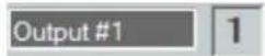
Figure 97. Output Name Field
- Delete the text and type the desired output name.
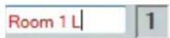
Figure 98. New Output Name
- Press the
key or navigate away from the field to confirm and apply the new output name. Press the key to navigate to and highlight the next name field.
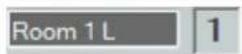
Figure 99. Renamed Output
NOTE: Follow the same procedure to edit an Output name.
Output Building Blocks
Extron building blocks are a quick configuration tool that can significantly reduce configuration time. A building block is a collection of processor and gain settings for an input or output processing chain. These building blocks have been built by Extron based on extensive use and testing with each intended application or specific device.

flowchart
graph LR
    A["TRIM"] --> B["DLY"]
    B --> C["FILT"]
    C --> D["DYN"]
    D --> E["ATT"]
    E --> F["Output #1"]
    F --> G["1"]
Figure 100. Accessing Building Blocks on an Output
Click the output number to open the Building Blocks dialog box.
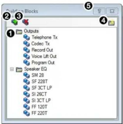
① Output Building Blocks List
② Add a Building Block Button
③ Delete a Building Block Button
④ New Folder Button
⑤ Building Blocks Help Button
Figure 101. Output Building Blocks Dialog Box
① Output Building Blocks List — Contains building blocks for output channels.
② Add a Building Block Button — Allows users to create custom building blocks, saving the currently applied gain and processor settings on the selected channel. Click the icon to open the Add a Building Block dialog box. This allows users to name the new custom building block and choose the folder to save the block to an existing folder, or create a new folder.
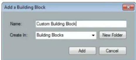
Figure 102. Add a Building Block Dialog Box
③ Delete a Building Block Button — Deletes the currently selected building block or building block folder. If default building blocks are deleted, they can be restored from the Organize Building Blocks dialog box.
4 New Folder Button —Creates a new folder or sub-folder.
⑤ Building Blocks Help Button — Opens the Building Blocks topic of the DSP Configurator Help file. This topic contains more information on the different types of building blocks for inputs and outputs.
Output Processing
The output processing chain in DSP Configurator is represented by a string of blocks (see figure 103 below). Each block contains a specific processor or type of processor. Each output contains the following processor chain:
- Output Trim Block
- Output Delay Block
- Output Filter Block
- Output Dynamics Block
- Output Attenuation Block

Figure 103. Output Processing Chain
Output Trim Block
Double-click the output Trim block to open the Post-mixer Trim dialog box.

Figure 104. Output Trim Block
The Post-mixer Trim dialog box provides pre-processing gain and attenuation control for the selected output.

① Output Name
② Post-mixer Trim Fader
③ Post-mixer Trim Text Box
④ OK Button
⑤ Cancel Button
Figure 105. Post-mixer Trim Dialog Box
① Output Name — This name changes to match the default or user defined output name.
② Post-mixer Trim Fader — Click and drag the trim fader to provide up to 12 dB of gain or 12 dB of attenuation in 0.1 dB steps. Click the trim fader and use the
③ Post-mixer Trim Text Box — Allows the user to enter a gain or attenuation value in 0.1 dB steps.
④ OK Button — Confirms changes made to the contained parameters and closes the Post-mixer Trim dialog box.
⑤ Cancel Button — Reverts any changes made to the contained parameters back to their states when the current instance of the Post-mixer Trim dialog box was opened and closes the dialog box.
Output Delay Block
One delay block is available for each output channel. This block functions the same as the mic/line input delay block (see Input Delay Block on page 37 for information on configuring the output delay block).
Output Filter Block
One filter block is available for each output channel. This filter block functions the same as the mic/line input filter block, except that there are 10 slots for filters instead of 5 (see Input Filter Block on page 26 for information on configuring output filters).
Output Dynamics Block
One dynamics block is available for each output channel. This block functions the same as the mic/line input dynamics block (see Input Dynamics Blocks on page 32 for information on configuring the output dynamics block).
Output Attenuation Block
Double-click the output Attenuation block to open the Attenuation dialog box.

Figure 106. Output Attenuation Block
The Attenuation dialog box provides attenuation control for the selected output.
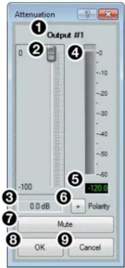
① Output Name ⑥ Polarity Button
② Output Attenuation Fader ⑦ Mute Button
③ Output Attenuation Text Box ⑧ OK Button
④ dBFS Meter ⑨ Cancel Button
⑤ dBFS Text Readout
Figure 107. Attenuation Dialog Box
① Output Name — This name changes to match the default or user defined output name.
② Output Attenuation Fader — Click and drag the trim fader to provide up to 100 dB of attenuation. Click the trim fader and use the
③ Output Attenuation Text Box — Allows the user to enter a gain or attenuation value in 0.1 dB steps.
④ dBFS Meter — Provides post-attenuation and pre-mute a readout of the output signal level.
⑤ dBFS Text Readout — Displays a numerical readout of the output signal level.
⑥ Polarity Button — Click this button to invert the signal polarity of the selected output. When the button displays the black + symbol on a gray field (☐), the polarity is normal. When the button displays the black - symbol on a yellow field (☐), the polarity is inverted.
⑦ Mute Button — Mutes the signal at the output stage.
⑧ OK Button — Confirms changes made to the contained parameters and closes the Attenuation dialog box.
9 Cancel Button — Reverts any changes made to the contained parameters back to their states when the current instance of the Attenuation dialog box was opened and closes the dialog box.
Aux Outputs
Four Aux outputs (non-V models) or eight Aux outputs (V models only) are available in the Aux Outputs panel. These outputs can be configured to route signal to a host computer as USB audio via the rear panel USB audio port or to a VoIP network via a rear panel LAN port (V models only).

flowchart
graph TD
    A["Input Line 1"] --> B["Add Out #1"]
    C["Input Line 2"] --> D["Aux Out #2"]
    E["Input Line 3"] --> F["Aux Out #3"]
    G["Input Line 4"] --> H["Aux Out #4"]
    B --> I["Aux Out #1"]
    D --> J["Aux Out #2"]
    F --> K["Aux Out #3"]
    H --> L["Aux Out #4"]
    style A fill:#f9f,stroke:#333
    style C fill:#f9f,stroke:#333
    style E fill:#f9f,stroke:#333
    style G fill:#f9f,stroke:#333
    style B fill:#ccf,stroke:#333
    style D fill:#ccf,stroke:#333
    style F fill:#ccf,stroke:#333
    style H fill:#ccf,stroke:#333
    style I fill:#cff,stroke:#333
    style J fill:#cff,stroke:#333
    style K fill:#cff,stroke:#333
    style L fill:#cff,stroke:#333
Figure 108. Aux Outputs Panel
Naming an Aux Output
- Click the Aux output name field.
Figure 109. Aux Output Name Field
- Delete the text and type the desired Aux output name.
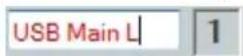
Figure 110. New Aux Output Name
- Press the
key or navigate away from the field to confirm and apply the new output name. Press the to navigate to and highlight the next name field.
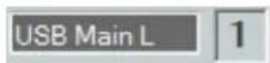
Figure 111. Renamed Aux Output
NOTE: Follow the same procedure to edit an Aux output name.
Aux Output Processing
The Aux output processing chain in DSP Configurator is represented by a string of blocks (see figure 112 below). Each block contains a specific processor or type of processor. Each Aux output contains the following processor chain:
- Aux Output Trim Block
- Aux Output Filter Block
- Aux Output Dynamics Block
- Aux Output Gain Block

Figure 112. Aux Output Processing Chain
Aux Output Trim Block
One trim block is available for each Aux output channel. This trim block functions the same as the output trim block (see Output Trim Block on page 61 for more information on configuring the Aux output trim block).
Aux Output Filter Block
One filter block is available for each output channel. This filter block functions the same as the mic/line input filter block (see Input Filter Block on page 26 for information on configuring the Aux output filter block).
Aux Output Dynamics Block
One dynamics block is available for each output channel. This block functions the same as the mic/line input dynamics block (see Input Dynamics Blocks on page 32 for information on configuring the Aux output dynamics block).
Aux Output Gain Block
Double-click the Aux output gain block to access a drop-down menu that displays USB and VoIP (V models only) output options. A selection must be made before audio passes through an Aux output.
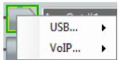
Figure 113. Aux Output Gain Block and Drop-Down Menu
The USB... and VoIP... selections in the Aux output mimic that of the Aux input (see Aux Input Gain Block on page 44).
NOTES:
- It is recommended that the USB 1 left and right channels be used for communication audio and USB 2 left and right channels be used for line input.
- When a VoIP line is assigned as the source for an Aux input, the same VoIP line is assigned to the corresponding Aux output. For example, if VoIP Line 1 is assigned to Aux input 1, VoIP line 1 is automatically assigned to Aux output 1 as well. Aux outputs can be reassigned to a different VoIP line.
Once an output has been selected, double-click the Aux output gain block again to open the Aux Output dialog box. This dialog box functions the same as the Aux input gain block (see Aux Input Gain Block on page 44 for information on configuring the Aux Output dialog box).
Expansion Outputs
Sixteen outputs are available in the Expansion Outputs panel. These outputs contain DSP processing capabilities and route audio to the rear panel EXP port when another EXP device is connected. These channels can also be transmitted to the Dante network on DMP 128 Plus AT models.
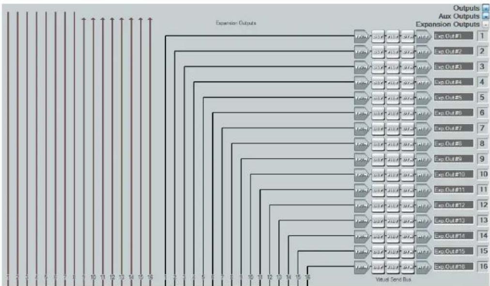
flowchart
graph TD
    A["Expansion Outputs"] --> B["Virtual Send Bus"]
    B --> C1["Exp Out#1"]
    B --> C2["Exp Out#2"]
    B --> C3["Exp Out#3"]
    B --> C4["Exp Out#4"]
    B --> C5["Exp Out#5"]
    B --> C6["Exp Out#6"]
    B --> C7["Exp Out#7"]
    B --> C8["Exp Out#8"]
    B --> C9["Exp Out#9"]
    B --> C10["Exp Out#10"]
    B --> C11["Exp Out#11"]
    B --> C12["Exp Out#12"]
    B --> C13["Exp Out#13"]
    B --> C14["Exp Out#14"]
    B --> C15["Exp Out#15"]
    B --> C16["Exp Out#16"]
Figure 114. Expansion Outputs Panel
Naming an Expansion Output
- Click the expansion output name field.
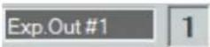
Figure 115. Expansion Output Name Field
- Delete the text and type the desired expansion output name.
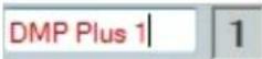
Figure 116. New Expansion Output Name
- Press the
key or navigate away from the field to confirm and apply the new output name. Press the to navigate to and highlight the next name field.
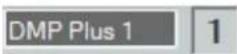
Figure 117. Renamed Expansion Output
NOTE: Follow the same procedure to edit an Expansion output name.
Expansion Output Processing
The expansion output processing chain in DSP Configurator is represented by a string of blocks (see figure 118 below). Each block contains a specific processor or type of processor. Each expansion output contains the following processor chain:
- Expansion Output Trim Block
- Expansion Output Delay Block
- Expansion Output Filter Block
- Expansion Output Dynamics Block
- Expansion Output Attenuation Block
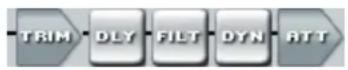
Figure 118. Expansion Output Processing Chain
Expansion Output Trim Block
Each expansion output contains a trim block. This block functions the same as the output trim block (see Output Trim Block on page 61 for information on configuring the expansion output trim block).
Expansion Output Delay Block
Each expansion output contains a delay block. This block functions the same as the mic/line input delay block (see Input Delay Block on page 37 for information on configuring the expansion output delay block).
Expansion Output Filter Block
Each expansion output contains a filter block. This block functions the same as the mic/line input filter block, except that there are 10 slots for filters (see Input Filter Block on page 26 for information on configuring expansion output filters).
Expansion Output Dynamics Block
Each expansion output contains a dynamics block. This block functions the same as the mic/line input dynamics blocks (see Input Dynamics Blocks on page 32 for information on configuring the expansion output dynamic filter).
Expansion Output Attenuation Block
Each expansion output contains an attenuation block. This block functions the same as the output attenuation block (see Output Attenuation Block on page 62 for information on configuring the expansion output dynamic filter).
Virtual Send Bus
The virtual send bus consists of mix points that allow inputs to be routed back to the virtual return input panel for additional mixing and processing (see Virtual Returns on page 48).
NOTE: Virtual Send Bus mix-points are highlighted in green.

bar
| Category | Assets (in €) | Aux. Outputs (in €) | Expansion Outputs (in €) | |---|---|---|---| | Assets | 300 | 300 | 300 | | Aux. Outputs | 300 | 300 | 300 | | Expansion Outputs | 300 | 300 | 300 |Figure 119. Virtual Send Bus Mix Points
Virtual Send channels cannot be routed to themselves. For example, Virtual Return A may be routed to Virtual Return B via the virtual send bus, but Virtual Return A cannot be routed to itself via the virtual send bus, and so on (see figure 120 below).
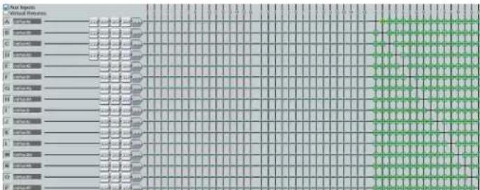
heatmap
| Category | Value | |---|---| | A | 30 | | B | 30 | | C | 30 | | D | 30 | | E | 30 | | F | 30 | | G | 30 | | H | 30 | | I | 30 | | J | 30 | | K | 30 | | L | 30 | | M | 30 | | N | 30 | | O | 30 | | P | 30 | The chart displays a grid of values for each category, with green cells indicating higher values. The values are estimated based on the grid layout and lack explicit numerical labels. The color scale is implied by the grid lines.Figure 120. Virtual Send Bus for Virtual Returns
Configuration Tools
This section contains information for configuring certain tools and options that are found under the Tools menu in DSP Configurator and covers the following topics:
- Presets • Firmware Loader
- Groups • Organize Building Blocks
• Digital I/O • Device Settings - Players - Options
• Macros • Expansion Bus
• Device Manager • Phone Dialer - Connect to or Disconnect from Device
Presets
Preset options are available from the Tools menu.
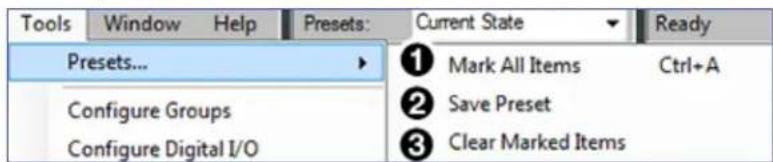
Figure 121. Presets Options
① Mark All Items — Marks all gain blocks, processor blocks, and mix-points in the main workspace. Performing this function before saving a preset ensures every element in the workspace is saved to the preset.
② Save Preset — Saves the marked blocks and mix points of the current configuration as a preset. When Save Preset is clicked, the following dialog box opens saying that only the elements marked with a green outline are saved to the preset (see figure 122 below). This option is only available if items are marked.
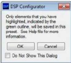
Figure 122. Preset Save Message
③ Clear Marked Items — Unmarks all currently marked elements.
Methods for Marking Items
Marked items are highlighted in green (see figure 123 below). There are four ways to mark items in DSP Configurator:
- Mark All — Press
- Mark Group — Click and drag the cursor to create a box around a group of items to mark them. Click and drag the cursor while holding the
key to create box around another group of items to mark them while keeping previous group marked. - Mark Series — Click the first item in the series to mark it, then press
- Mark Multiple Individual – Click the first item to mark it and press

flowchart
graph LR
    A["ANG GAIN"] --> B["FILT"]
    B --> C["REC"]
    C --> D["DYN"]
    D --> E["DYN"]
    E --> F["DELY"]
    F --> G["DUCK"]
    G --> H["AM"]
    H --> I["GAIN"]
Figure 123. Marked Items Highlighted in Green
Configuring Presets
- Create a configuration to be saved as a preset (see DSP Configurator Software on page 10).
- Mark the items that will be included in the preset.
- Select Tools > Presets > Save Preset.
- From the Save a Preset dialog box, enter the preset number (1 through 32) in the Preset Number field (see figure 124, ① below). Preset slots that do not already have a preset assigned read [unassigned]. Enter a name into the Preset Name field (②, 12 character maximum).
- Click OK (③) to save the preset.
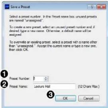
Figure 124. Save a Preset Dialog Box
NOTE: When a configuration file is pushed to a DMP 128 Plus, presets contained within that file are available for recall from DSP Configurator or SIS commands.
- The preset is saved and is available from the Presets drop-down menu at the top of the main workspace.
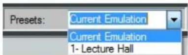
Figure 125. Presets Drop-Down
Groups
Groups allow master control of Gain, Mute, Bass, Treble, and Loudness for groups of channels. Groups are used in macros, ACP panels, and other control configurations.
Click Tools > Configure Groups to open the Configure Groups dialog box.
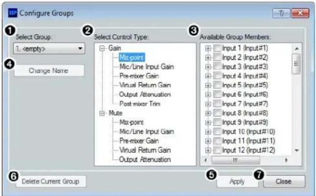
① Select Group
⑤ Apply Button
② Select Control Type
⑥ Delete Current Group Button
③ Available Group Members
⑦ Close Button
④ Change Name Button
Figure 126. Group Controls Dialog Box
① Select Group — Provides a drop-down menu to select the number of the group to be configured. If the group has been configured and named, the group name appears next to the group number. If the group slot is empty, it reads
② Select Control Type — Group controls can manage Gain, Mute, Bass, or Treble for the specified inputs, mix-points, or outputs. From the Select Control Type panel, select the type of control from the Gain, Mute, Bass, or Treble lists.
NOTE: Bass and Treble are only available if the Bass and Treble filters are inserted on a channel and only allow channels with the filters to be placed in a group.
③ Available Group Members — This section populates according to the selected control type and lists all inputs, mix-points, and outputs available to be added as group members. Check the box next to a member to add it to the group. Group members must be the same control type. The maximum number of group members for a single group is 128.
NOTE: Loudness processors can be selected from input and output gain stages.
④ Change Name Button — Once a group has been created, select it from the Select Group drop-down menu (1), click Change Name to change the name of the selected group.
⑤ Apply Button — Click Apply after changes to a group have been made. The Confirm Group Details dialog box opens allowing the group name and number to be edited. Click OK to apply group changes.
⑥ Delete Current Group Button — Select a group from the Select Group drop-down menu and click Delete Current Group to delete the group.
⑦ Close Button — Click Close to close the dialog box. Any changes that have not been applied will be lost.
Configuring Groups
To create a new group:
- Select Tools > Configure Groups to open the Configure Groups dialog box.
- From the Select Group drop-down, select a group slot to configure (see figure 127, ① below).
- From the Select Control Type panel (②), expand a control type.
- Choose which gain stage the control type affects.
- From the Available Group Members panel, select the channels to be configured as group members (③).
- Click Apply ( 4).
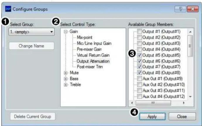
Figure 127. Configure Groups Dialog Box
- Confirm the group number and name from the Confirm Group Details dialog box (see figure 128, 5 below).
- Click OK to confirm all details and create the group (6).
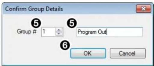
Figure 128. Confirm Group Details Dialog Box
To edit an existing group:
- Select Tools > Configure Groups to open the Configure Groups dialog box (see figure 129 below).
- From the Select Group drop-down (figure 129, ① below), select an existing group to edit.
- From the Select Control Type panel (②), expand a control type.
- Choose which gain stage to edit.
- From the Available Group Members panel (③), select or deselect channels that will be members of the group.
- Click Apply ( 4).
- From the Confirm Group Details dialog box, the group number and group name can be edited (5).
- Click OK to confirm the group details (6).
- When the Overwrite Group dialog box opens, click OK to confirm the changes made to the group.
To edit only a group name or group number:
- Choose the group from the Select Group drop-down (①).
- Click Change Name (7).
-
From the Change Group Name dialog box, enter the new group number or group name into the respective fields (5).
-
Click OK (6).
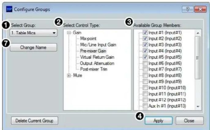
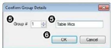
Figure 129. Editing a Group
Digital I/O
The DMP 128 Plus rear panel has eight sets of digital I/O ports (see figure 2, B on page 5). Each set has one digital input and two digital outputs. These digital I/O ports can be configured from DSP Configurator. The Configure Digital I/O dialog box allows the user to select from a list of actions, then have the script complied and implemented on the device.
Each of the digital I/O sets has three panels for configuration. One panel for Digital In and two for Digital Out. The Digital In panel contains a drop-down for the action and a drop-down for the element being acted upon. Digital Out 1 and Digital Out 2 contain drop-down menus for the mode and the input being acted upon.
Click Tools > Configure Digital I/O to open the Configure Digital I/O dialog box.
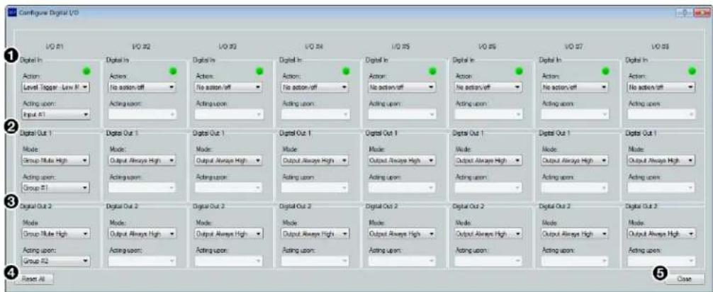
① Digital In Panel
④ Reset All Button
② Digital Out 1 Panel
⑤ Close Button
③ Digital Out 2 Panel
Figure 130. Configure Digital I/O Dialog Box
① Digital In Panel — Provides the following configuration options for the digital input.
a. Status LED — Displays the current status of the digital input. When the input is high, the LED lights green. When the input is low, the LED is black. When DSP Configurator is in Emulate mode, the LED is gray.
b. Action Drop-Down — Provides a list of actions for the digital input to trigger, depending on the status of the digital input.
c. Acting Upon Drop-Down — Provides a list of inputs, groups, macros, and presets for the action to affect.
② Digital Out 1 Panel — Provides the following configuration options for the digital output.
a. Mode Drop-Down — Provides a list of modes for the first digital output.
b. Acting Upon Drop-Down — Provides a list of inputs, groups, macros, and presets for the mode to affect.
③ Digital Out 2 Panel — Contains drop-downs identical to Digital Out 1 panel for configuring Digital Out 2.
④ Reset All Button — Resets all I/O configuration data to default.
⑤ Close Button — Closes the dialog box, retaining the configuration data.
Configuring Digital I/O
- In the Digital In panel, select an action from the Action drop-down.
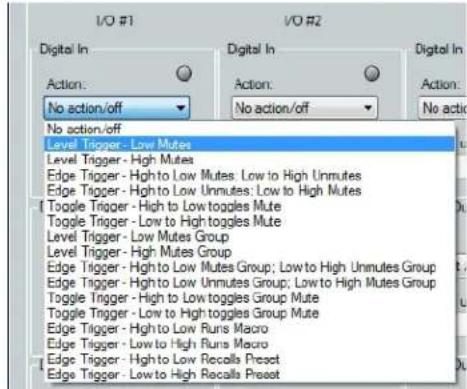
Figure 131. Selecting Digital In Action
- From the Acting upon drop-down, select the input, group, preset, or macro affected by the action.
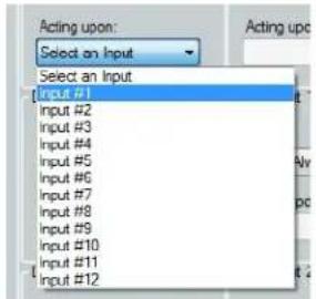
Figure 132. Selecting Digital In Acting Upon
- From the Digital Out 1 panel, select a mode for the digital output from the Mode drop-down.
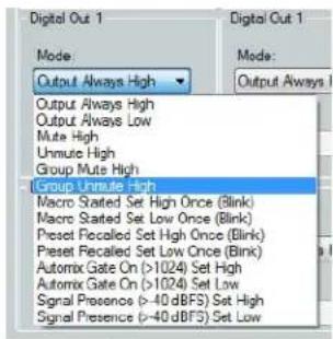
Figure 133. Selecting Digital Out 1 Mode
- From the Digital Out 1 Acting upon drop-down, select an input, group, preset, or macro affected by the mode.
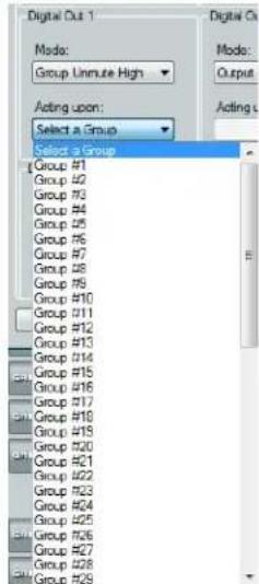
Figure 134. Selecting Digital Out 1 Acting Upon
- From the Digital Out 2 panel, select a mode for the digital output from the Mode drop-down.
- From the Digital Out 2 Acting upon drop-down, select the input, group, preset, or macro affected by the mode.
- Repeat steps 1 through 6 for additional Digital I/O configurations.
- Click Close to close the Configure Digital I/O dialog box.
- To save the Digital I/O configuration, click File > Save or press
To push the Digital I/O configuration to a DMP 128 Plus:
- Connect to a DMP 128 Plus in Live mode (see Live and Emulate Panel on page 18) and follow the Digital I/O configurations steps listed starting on page 73. Changes made in the Configure Digital I/O dialog box when connected Live are applied directly to the DMP 128 Plus.
-or-
- Follow the Digital I/O configuration steps listed starting on page 73 while in Emulate mode.
- Connect to a DMP 128 Plus in Live mode and perform a configuration file push (see Live and Emulate Panel on page 18).
Players
The Configure Players dialog box allows the user to upload audio files to a DMP 128 Plus and is available when connected Live to the device. Once the audio file is uploaded, it may be assigned to one of eight players. Configured players may then be assigned to any of the Aux inputs and routed to the desired output for audio file playback (see Aux Inputs on page 43).
![Configure Players File in the device: Byte Left: 97MB FileName Size (KB) inknake.wav_ConvertedByDSP... $55 sinewave.wav_ConvertedByDSP... $55 whitenoise.wav_ConvertedByDSP... $55 Add File to Device Remove File from Device Players (drag File to Player to Assign): No. Filename Status Repeat Repeat Delay 1 [unassigned] 0 2 [unassigned] 0 3 [unassigned] 0 4 [unassigned] 0 5 [unassigned] 0 6 [unassigned] 0 7 [unassigned] 0 8 [unassigned] 0 Sold Players Stop Player Clear Player](/content/2026/05/792275/images/781e6b35ca04557e62ef2c504435112d575166c71f367c7eeb26400e9276385e.jpg)
① Files in the Device
② Add File to Device Button
③ Remove File from Device Button
4 Players
Figure 135. Configure Players Dialog Box
⑤ Start Player Button
⑥ Stop Player Button
⑦ Clear Player Button
① Files in the Device — Lists the audio files stored on the DMP 128 Plus. The file names and extensions are listed in the Filename column, with the size of the file listed in the Size (KB) column.
NOTE: Default files in the device are white noise, pink noise, and sine wave.
② Add File to Device Button — Opens the Select Audio file to load to device dialog box where an audio file is selected to load onto the DMP 128 Plus.
NOTES:
- Only .wav, .mp3, .wma, .aiff, .aac, and .raw audio file types are accepted.
- All audio files are converted to .raw at a 48 kHz sampling rate when uploaded to the DMP 128 Plus.
- File names containing spaces are not accepted.
③ Remove File from Device Button — Removes the selected file from the device.
4 Players — Contains 8 players that can have audio files assigned to them. Each player contains a Repeat check box that repeats the audio file until Stop Player is selected. The Repeat Delay field specifies the number of seconds between each repeat of the audio file. To assign an audio file from the device to one of the 8 players, click and drag the desired audio file to the desired player. The filename of the player changes from [unassigned] to the name of the file assigned to the player.
⑤ Start Player Button — Starts playing the audio file assigned to the selected player.
NOTE: This button is only available when the player is inserted into the Aux input (see Aux Inputs on page 43 for more information).
⑥ Stop Player Button — Stops playing the audio file assigned to the selected player.
⑦ Clear Player Button — Removes the assigned audio file from the selected player, but does not remove it from the device. Player reverts to [unassigned].
Configuring Players
To upload an audio file:
- Enter Live mode to connect to a DMP 128 Plus (see Live and Emulate Panel on page 18).
- Click Tools > Configure Players.
- From the Configure Players dialog box, click Add File to Device (see figure 135, ② on the previous page).
- From the Select Audio file to load to device dialog box, locate the desired audio file and select it (see figure 136, ① below).
NOTE: File names containing spaces are not accepted.
- Click Open (②).
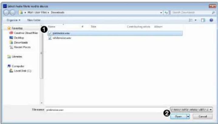
Figure 136. Selecting an Audio File to Upload
- A Loading... status bar appears in the menu status field at the top of the main workspace. When the file is loaded successfully, the field reads File Loaded Successfully!

Figure 137. Loading Bar and File Uploaded Successfully
- Click OK in the Upload Complete dialog box.
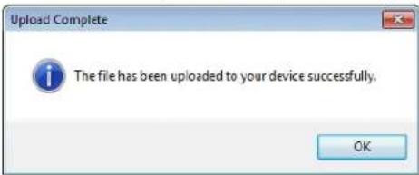
Figure 138. Upload Complete Dialog Box
To assign an audio file to a player:
- Select the audio file from the Files in the device panel.
- Click and drag the audio file to the desired player (pinknoise.wav is being assigned to Player 1 in figure 139 below).
- When the file has been assigned to a player, the player Filename field displays the name of the audio file assigned.
![Configure Players Files in the device: Bytes Left: 95MB Filename Size (KB) pinknoise.wav ConvertedByDSP... 953 Add File to Device Remove File from Device Players (drag file to Player to Assign): No. Filename Status Repeat Repeat Delay 1 [unassigned] 0 2 [unassigned] 0 3 [unassigned] 0 4 [unassigned] 0 5 [unassigned] 0 6 [unassigned] 0 7 [unassigned] 0 8 [unassigned] 0 Start Player Stop Player Clear Player](/content/2026/05/792275/images/ed41ebc7964eb4f4e540af9e5a6a4003c3d527be0424d980d1a218cec2df9813.jpg)
Figure 139. Assigning Audio File to Players
To start, stop, or clear a player:
- Click a player with an audio file assigned to it (see figure 140, ① below).
- Check the Repeat checkbox (②) to repeat the audio file after it has been played (optional).
- Enter the amount of time in seconds the player should wait before repeating the file in the Repeat Delay field ( ③) (optional).
- Click Start Player ( 4).
NOTE: The player must be assigned to an Aux input before Start Player and Stop Player are available (see Aux Input Gain Block on page 44).
- To stop the player, highlight the player with a single click, then click Stop Player ( ⑤).
- To clear the player of its audio file, highlight the player with a single click, then click Clear Player ( ⑥).
![Configure Players Files in the device: Bytes Left: 98MB Filename Size (KB) pinknoise_way_ConvertedByDSP_ 959 No. Filename Status Repeat Repeat Delay 1 pinknoise.wav_ Stopped ✓ 0 2 [unassigned] 3 [unassigned] 4 [unassigned] 5 [unassigned] 6 [unassigned] 7 [unassigned] 8 [unassigned] Add File to Device Remove File from Device Start Player Stop Player Clear Player](/content/2026/05/792275/images/efd3310d4386c45ff4ff6310f4994a3cb933ca79ac314de664bd54dba5baabc5.jpg)
Figure 140. Starting, Stopping, and Clearing Players
Macros
Macros are sets of actions that can affect the local DMP 128 Plus and other Extron products on the same TCP/IP network. They can be configured in Emulate or Live mode via an Ethernet connection only, and they can be saved to a configuration file or pushed to DMP 128 Plus internal memory. Macros are comprised of up to 32 actions that occur in sequence to quickly configure a system for specific applications.
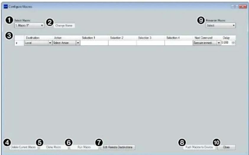
Figure 141. Configure Macros Dialog Box
① Select Macro Drop-Down — Select an empty macro slot to configure or select an existing macro to edit from this drop-down menu.
② Change Name Button — Click this button to enter a new name for a previously configured macro. Press
③ Macro Configuration Form — Up to 32 actions can be configured in this form. When one action is configured, a new line appears to configure the next action in the macro.
④ Delete Current Macro Button — Deletes the macro currently selected from the Select Macro drop-down.
⑤ Clone Macro Button — Clones the currently selected macro to a new macro slot.
⑥ Run Macro Button — Runs the macro currently selected from Select Macro drop-down, performing all of the configured actions in sequential order. This is only available when connected to a DMP 128 Plus in Live mode via the LAN or VOIP 1 port.
⑦ Edit Remote Destinations Button — Opens the dialog box to edit data for remote devices being configured by the actions in a macro. Remote devices in the network can also be added from this dialog box (see the Configure Macros topic in the DSP Configurator Help file). This is only available when connected in Live mode.
⑧ Push Macros to Device Button — Pushes all macros to a connected DMP 128 Plus. Once the macros are on the device, they can be run by control systems or DSP Configurator. This button is only available when connected Live to a DMP 128 Plus (see Live and Emulate Panel on page 18).
⑨ Power-on Macro Drop-Down — Select an existing macro to run whenever the DMP 128 Plus is powered on.
10 Close Button — Closes the Configure Macros dialog box, retaining macros that have been created or edited. Actions that have not been completely configured show a symbol to the left of the Destination field in the macro configuration form. Actions showing the Symbol are not saved when the dialog box is closed.
Configuring a Macro
- Click Tools > Configure Macros. The Configure Macros dialog box opens.
- Select an empty macro slot from the Select Macro drop-down.
- From the Destination drop-down, select a destination for the macro action. Choose Local for the local DMP 128 Plus, or Add Destination... for a remote destination. If choosing Local, proceed to step 4.
NOTE: Macro commands can only be sent to remote destinations via the LAN/VoIP 1 port (V models only).
a. After selecting Add Destination..., the Edit Remote Destinations dialog box opens.
b. Complete the form in the dialog box, including username and password, if required.
c. Select Apply to add the device to the drop-down in the Destinations column.
d. Click Close to close the Edit Remote Destinations dialog box.
e. Select the newly created remote destination from the Destination drop-down.
-
From the Action drop-down, select an action to be configured.
-
Recall Preset — Recall an existing preset.
- Set Group Gain — Set the level of an existing gain group.
- Group Gain Inc/Dec — Set the increment/decrement values of an existing gain group.
- Set Group Mute — Mute or unmute an existing mute group.
- Gain — Set the gain of a specific gain block on a specific channel.
- Mute — Mute or unmute a specific gain block on a specific channel.
- Set Phantom Power – Enable or disable phantom power on a specific Mic/Line input channel.
- Meters On/Off — Enable or disable level meters at the input gain or output attenuation stages of a specific channel.
- Start Player — Starts a selected player.
- Stop Player — Stops a selected player.
- SIS Command — Type in a single SIS command to perform an action not listed above (see Remote Communication and Control on page 123).
NOTE: Use the w key in place of Esc and the | (pipe) key in place of ←.
- Set Input Format — Specify whether mic/line inputs receive analog signal from the inputs or digital signal via the Dante network (see 9 in figure 45 on page 25).
- Dial Number — Use a specific VoIP line to dial a string.
- Dial Digits — Use a specific VoIP line and line appearance to dial a predetermined number, such as an extronsion number or conference pin.
• End Call — End calls on a specific line or all appearances of a VoIP line.
-
Once the action is chosen, up to four additional selections are made available. These additional selections must be completed in order to proceed to the next macro step. For example, if Set Group Gain is the selected action, Selection 1 prompts the selection of a gain group to be affected and Selection 2 determines the gain level of the selected group.
-
When all of the action selections are configured, a new line appears at the bottom of the form so another action can be configured.
-
From the Next Command drop-down, select whether the DMP 128 Plus waits for an SIS response from each action before executing the next action in the macro or executes the next command immediately without waiting for an SIS response. The default is Execute immediately. Responses can be viewed through Extron Dataviewer and follow SIS response syntax (see DSP SIS Commands on page 141).
a. Use the the Delay field to enter the amount of delay in seconds. The default is 0.000 seconds of delay.
-
Click Change Name at the top of the dialog box and enter a new name for the macro in the Select Macro text field. Default macro names are Macro 1, Macro 2, and so on.
-
Up to 32 actions can be configured per macro. Follow steps 3 through 7 to configure additional actions. Right click the left-most field in an action to cut, copy, or paste actions in a macro.
-
Connect Live to the DMP 128 Plus and click Push Macro to Device to push it to the DMP 128 Plus. Once the macro has been pushed, it can be run via DSP Configurator, a control system, or SIS commands.
NOTES:
- A macro cannot be run until it is pushed to the device. Edits made to an existing macro must also be pushed to the device.
- Macro configuration data is saved on a per-line basis. When an action is completely configured, the data is saved even if the Configure Macros dialog box is closed.
- Macro configurations are saved when the DSP Configurator configuration file is saved.
- If DSP Configurator is closed without saving the configuration file or pushing the macro to a DMP 128 Plus, unsaved macro configuration data is deleted.
To delete a Macro:
- Click Tools > Configure Macros.
- From the Select Macro drop-down, choose the macro to be deleted.
- Once the macro information is displayed, click Delete Current Macro in the bottom left corner of the Configure Macros dialog box.
To clone a Macro:
- Click Tools>Configure Macros.
- From the Select Macro drop-down, choose the macro to be cloned.
- Click Clone Macro at the bottom of the Configure Macros dialog box.
- Use the drop-down in the Clone Macro dialog to select a destination for the cloned macro. By default, the next empty macro slot is selected as the destination.
NOTE: If a macro already exists in the selected destination, a warning message appears below the drop-down, warning that the existing macro will be overwritten with the cloned macro.
- Click OK to clone the macro or Cancel to cancel the action.
- After the macro is cloned, the new macro is displayed in the Configure Macros dialog box. The cloned macro has a default macro name.
To run a Macro:
- Connect to the DMP 128 Plus in Live mode (see Live and Emulate Panel on page 18).
- Click Tools > Configure Macros.
- From the Select Macro drop-down, choose the macro to be run.
- Once the macro information is displayed, click Run Macro.
-or-
- Connect to the DMP 128 Plus in Live mode (see Live and Emulate Panel on page 18).
- Select the macro to be run from the Run Macro drop-down in the tool bar.
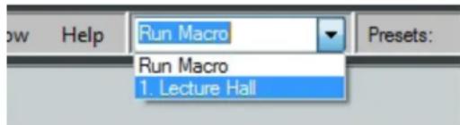
Figure 142. Run Macro Drop-Down
To edit remote destinations:
- Click Edit Remote Destinations from the Configure Macros dialog box.
- Select an existing device from the Unique Device Name drop-down.
- Edit the information for the device or click Delete to remove the selected device.
- Click Apply to save changes made to the remote destination.
- Click Close to close the Edit Remote Destinations dialog box.
NOTE: See step 3 on page 79 for information regarding adding a destination.
Manipulating Macro Actions
After a macro action has been fully configured, it can be cut, copied, pasted, inserted, or deleted. Right-click the left-most box in the action line item (see figure 141, ③ on page 78) and select an option from the drop-down menu.
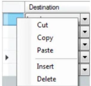
Figure 143. Macro Action Manipulation Drop-Down
To cut a macro action:
- Right click the box furthest to the left in the action list item to be cut.
- Select Cut. The action is removed from the list and placed in the clipboard.
To copy a macro action:
- Right click the box furthest to the left in the action list item to be copied.
- Select Copy. The action is copied to the clipboard.
To paste a macro action:
- Right click the box furthest to the left in the action list item where the action is to be pasted.
- Select Paste. The action is copied to the list item. Any existing action data is overwritten.
To insert a macro action:
- Cut or copy a macro action to be inserted.
- Right click the box furthest to left in the action list item directly below where the action in the clipboard is to be inserted.
- Select Insert. The action is inserted from the clipboard above the action that was right clicked in step 1.
To delete a macro action:
- Right click the box furthest to the left in the action to be deleted.
- Click Delete.
Device Manager
Device Manager is used to configure and switch between multiple devices in Live or Emulate mode within DSP Configurator (see Live and Emulate Panel on page 18).
Devices can be placed and ordered in user-created folders for easily tracking systems with devices across multiple rooms. When Device Manager contains multiple devices, all device configurations are saved in a single DSP Configurator file.
Select Tools > Device Manager to open the Device Manager dialog box.
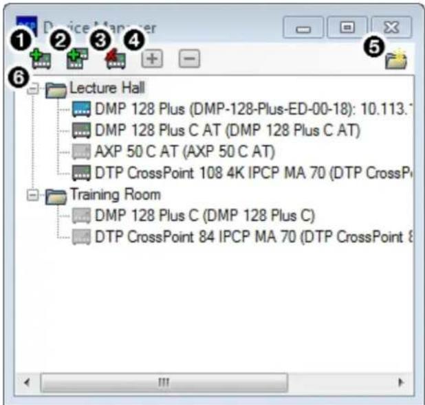
① Add Device Button
② Clone Device Button
③ Remove Device Button
④ Expand and Collapse All Buttons
⑤ New Folder Button
⑥ Device List Panel
Figure 144. Device Manager Dialog Box
① Add Device Button — Click the button to open the DSP Configurator splash screen to select another device to be configured. As a device is chosen or connected, it is added to the Device Manager dialog box.
2 Clone Device Button —Click the button to clone the currently selected device. When a device is cloned, information within the device configuration file is also cloned.
NOTE: If Live mode is enabled, a backup may need to be performed before the device can be successfully cloned.
3 Remove Device Button — Click the button to remove the currently selected device from the device manager. Select a folder and click this button to delete the folder and all devices it contains.
4 Expand and Collapse All Buttons — Click the icon to expand all folders and show the devices it contains. Click the to collapse all folders.
5 New Folder Button — Click the button to create a new folder to drag a device into.
6 Device List Panel — Lists the devices and folders in Live and Emulate mode. From this panel, devices can be clicked and dragged into folders, placed in custom order, and folders can be renamed. If the device is connected via LAN, the device IP is displayed. Double-clicking a device in this list will initiate a pull (see Connect to a DMP 128 Plus in Live Mode on page 18).
The color of the icon next to a device name indicates Live or Emulate status, as well as whether the device is configured as a Primary or Secondary EXP device. Devices with color icons are in Live mode. Devices with grayed icons are in Emulate mode. Devices with blue icons are configured as Secondary units (see Expansion Bus on page 94).
Managing Devices in Device Manager
To add a device:
- Click Tools > Device Manager to open the Device Manager dialog box.
- Click the Add Device button (see figure 145, ① below).
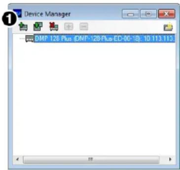
Figure 145. Adding a Device
-
From the DSP Configurator splash screen drop-down, select the device to be added to Device Manager (see figure 146, ② below). Select Connect... to open the Connect to device... dialog box and directly connect with a device. When connecting directly, DSP Configurator performs a pull of the newly connected device configuration.
-
Click OK (③).
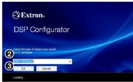
Figure 146. Selecting a Device to be Added
To arrange devices into a folder:
-
From the Device Manager dialog box, click the New Folder button (see figure 147, ① below).
-
Enter a name for the folder. The text for the folder name is automatically highlighted and ready to be edited (②).
NOTE: Folders can be renamed later by clicking twice on the folder name and editing the text.
-
Press
. -
Click and drag devices over the folder name and release to insert the devices into a folder (3).
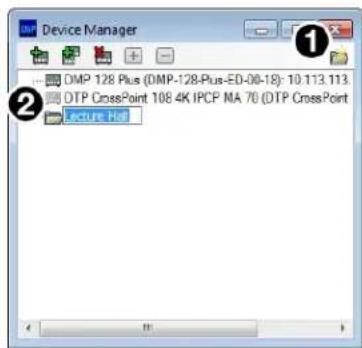
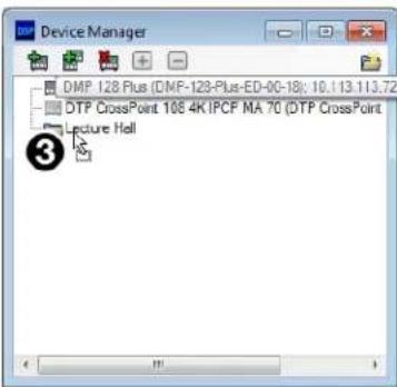
Figure 147. Arranging Devices Into a Folder
Connect to or Disconnect from Device
When DSP Configurator is in Emulate mode, this selection in the Tools menu reads Connect to Device and opens the Connect to device... dialog box when selected. When DSP Configurator is in Live mode and connected to a device, this selection reads Disconnect from Device and disconnects DSP Configurator from the current device when selected, and returns to Emulate mode.
For detailed instructions on connecting to a DMP 128 Plus see Connect to a DMP 128 Plus in Live Mode on page 18. For detailed instructions on disconnecting from a DMP 128 Plus see Exit Live Mode and Enter Emulate Mode on page 20.
Firmware Loader
Select Tools > Firmware Loader to open the Extron Firmware Loader software from DSP Configurator. Firmware Loader assists users in updating firmware or uploading new firmware to devices via RS-232, USB, or TCP/IP connection. Refer to the Firmware Loader Help file for more information in using the Firmware Loader software.
NOTES:
- Extron Firmware Loader software must be installed on the host PC in order for it to be opened.
- TCP/IP connection is recommended for updating firmware.
Downloading Firmware Updates
- Go to www.extron.com and click the Download tab at the top of the page (see figure 148, ① below).
- From the Download page, select the Firmware link (②) near the middle of the page.
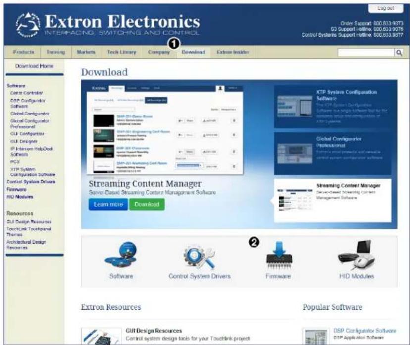
Figure 148. Download Page and Firmware Link
- The Firmware link opens the firmware Download Center page. Click the D from the alphabet list at the top of the page (see figure 149, ③ below).
- Select the Download link (④) at the right side of the DMP 128 Plus listing.
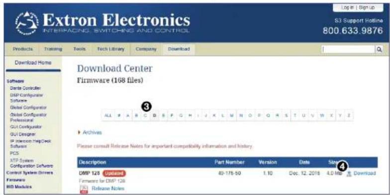
Figure 149. Download Center and Firmware Link
- After clicking the Download link, select Run from the next page to run the firmware installer (see figure 150, ⑤ below). Alternatively, select Save (⑥) to save the firmware installer and install the firmware at a later time.
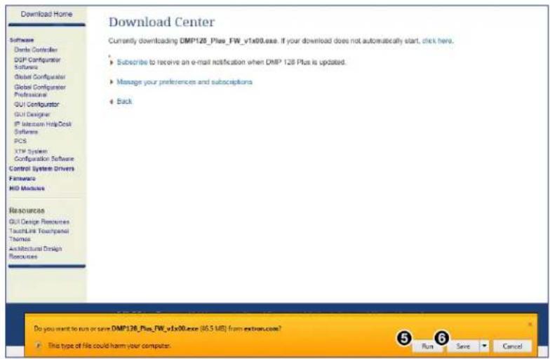
Figure 150. Firmware Installer Run or Save
NOTE: When firmware is version 1.01.0010 or higher, the firmware cannot be downgraded to a version lower than 1.01.0010.
- Once the installer has been run, the Firmware Upgrade dialog box opens, click Next to begin the installation process (see figure 151, ⑥ below).
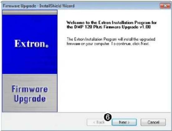
Figure 151. Firmware Upgrade InstallShield
-
The terms of installation must be agreed to. Select the I accept... radio button (see figure 152, ⑦ below).
-
Click Next ( ⑧).
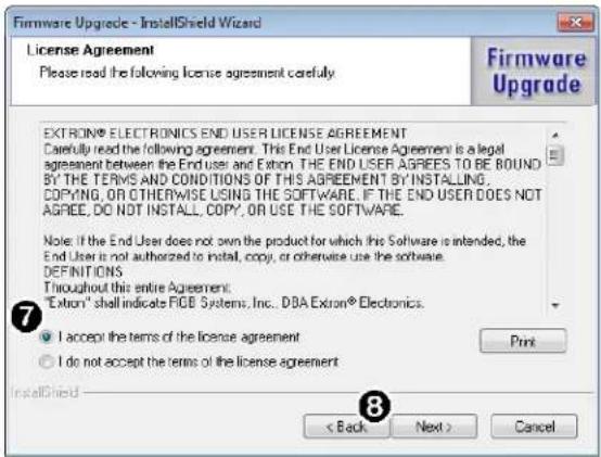
Figure 152. Firmware License Agreement
-
An installation status dialog box opens that displays the completion status of firmware download and installation.
-
When the firmware is installed, the Firmware Upgrade dialog box displays that the installation is complete and the install location of the firmware file. By default, firmware is installed in:
Program Files > Extron > Firmware > DMP_128_Plus > vx.xx
If the View Firmware Release Notes checkbox is checked (see figure 153, ⑨ below), a PDF of the firmware release notes opens automatically. The box is checked by default.
Click Finish to close the dialog box (10).
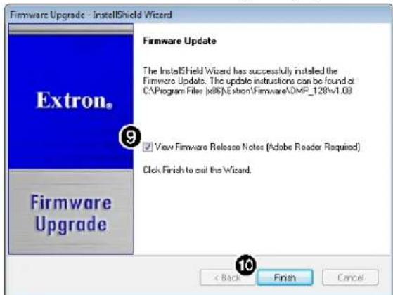
Figure 153. Firmware Installed Dialog Box
Organize Building Blocks
Extron building blocks are a quick configuration tool that can significantly reduce configuration time. A building block is a collection of processor and gain settings for an input or output processing chain. Building blocks have been built by Extron based on extensive use and testing with each intended application or specific device. The Organize Building Blocks dialog box allows users to organize building blocks to their preference, import new building blocks, export existing building blocks, delete building blocks, and restore default building blocks that may have been deleted by the user. Building blocks in the Organize Building Blocks dialog are organized into folders for easily locating building blocks for a multitude of applications.
Select Tools > Organize Building Blocks to open the Organize Building Blocks dialog box.
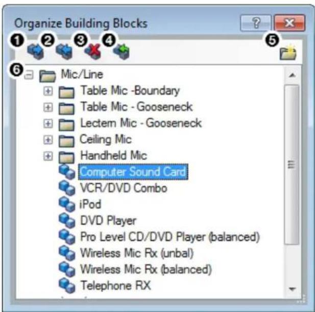
① Export Building Blocks File Button
④ Restore Default Building Blocks Button
② Import Building Blocks File Button
⑤ New Folder Button
③ Delete Building Block Button
⑥ Building Blocks Panel
Figure 154. Organize Building Blocks Dialog Box
① Export Building Blocks File Button — Click the button to export the selected building block file to be saved to a disk.
NOTE: Building block files have an XML extension.
② Import Building Blocks File Button — Click the "button" to browse the computer for building block files to import to DSP Configurator.
③ Delete Building Block Button — Click the "button" to delete the currently selected building block.
4 Restore Default Building Blocks Button — If default building blocks that come installed with DSP Configurator are deleted, click the button to restore them.
NOTE: Only the default building blocks can be restored with this function. User created building blocks are not restored if deleted.
TIP: To avoid accidentally deleting user created building block files, once they are created, export them to a safe location on the disk. This creates a backup copy of the building block file, should it be deleted by the user by mistake.
⑤ New Folder Button — Click the button to create a new folder that building blocks can be dragged into. Upon creation, a default folder name is highlighted and a custom name can be entered. Click a folder name twice to edit the folder name.
6 Building Blocks Panel — This panel contains folders and building blocks. Click and drag building blocks to change their order or place them inside folders. Click a building block name twice to edit the building block name. Click a folder name twice to edit the name of the folder.
Device Settings
The Device Settings dialog box provides access to general settings of the DMP 128 Plus. Select Tools >Device Settings to open the Device Settings dialog box. Device settings are only available when connected live to a device.
Within the Device Settings dialog box, the following tabs are available:
- Unit Info
IP Settings - Passwords
- Serial Settings
- Date/Time
- Dante Device
Unit Info
The Unit Info tab displays the unit name, firmware version, device model, device part number, and device MAC address. Click in the Unit Name field to rename the device within the listed naming parameters. Click Apply to save the changes.
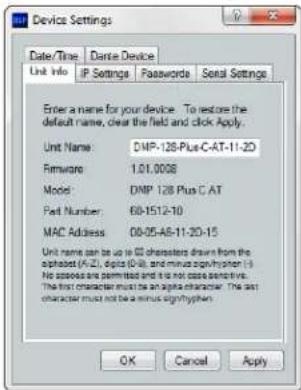
Figure 155. Unit Info Tab
IP Settings
The IP Settings tab allows the user to view and edit the IP address, gateway IP address, subnet mask, and DHCP status of the unit. The checkbox to the left of each parameter must be checked before any changes can be made to that parameter. Click Apply to save the changes.
NOTE: Changing DHCP from 0n to 0ff resets the IP address to the factory default (192.168.254.254).
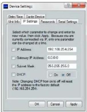
Figure 156. IP Settings Tab
Passwords
The Passwords tab allows the user to create or edit user and administrator passwords. An administrator password must be created in order to create a user password. The checkbox to the left of the password type (Admin or User) must be checked before creating or editing passwords. Click Apply to save the changes.
NOTE: Passwords only apply to IP connections and can be up to 12 characters in length.
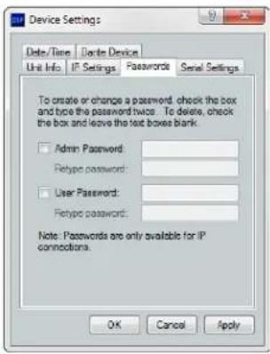
Figure 157. Passwords Tab
Serial Settings
The Serial Settings tab allows users to change the baud rate of the rear panel RS-232 port. Click Apply to save the changes.
NOTE: The recommended baud rate for the DMP 128 Plus is 38400.
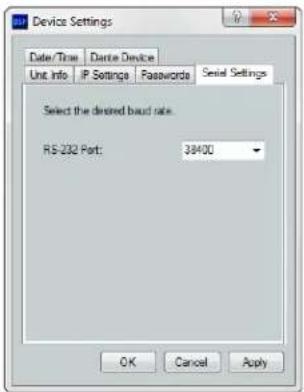
Figure 158. Serial Settings Tab
Date/Time
To set the date and time:
- Click the Set Local button to sync the date and time information with the date and time on the connected PC.
- Set the time zone by using the Zone drop-down.
- Use the Daylight Savings radio buttons to enter the daylight saving region, or leave off (default).
-or-
- Enter the desired date in the Date field. A drop-down calendar is available for date selection.
- Enter the desired time in the Time field by clicking on the hours and entering the hour, then clicking on the minutes and entering the number of minutes.
- Set the time zone by using the Zone drop-down.
- Use the Daylight Savings radio buttons to enter the daylight saving region, or leave off (default).
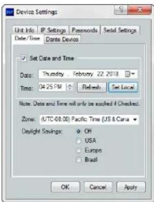
Figure 159. Date/Time Tab
NOTE: The information displayed in the Date/Time tab is static. In order to update the information to reflect the current time, click Refresh.
Dante Device
This tab allows the DMP 128 Plus Dante settings to be configured within DSP configurator without opening Dante Controller.
ATTENTION: It is essential that a Dante device be named immediately after it is connected to the Dante network and before audio connections with other devices are established. Existing connections are removed when a device is renamed.
Dante Device Name
A Dante device can be renamed to identify the device on the audio network.
To assign the Dante device name:
- Select Tools > Device Settings.
- Use the arrows to navigate to the Dante Device tab (see figure 160, ①).
- Click the Device name text box (②).
- Enter a device name for the Dante interface.
- Click Apply ( ③). A confirmation dialog box opens.
- Click Yes, to confirm existing connections will be removed after the name is changed.
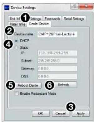
Figure 160. Dante Device Tab in Device Settings Dialog Box
Dante Device Network Settings
To configure Dante network settings:
-
Select the DHCP or Static IP radio buttons (4). If using DHCP, the DMP 128 Plus Dante interface will be assigned an IP address by the DHCP server and Dante network configuration is complete. If Static IP is selected, proceed to step 2.
-
Enter a valid network configuration into the respective fields.
- Click Apply.
To reboot the Dante interface:
- Click Reboot Dante (5 on the previous page). Only the Dante interface will reboot, not the entire DMP 128 Plus.
To refresh the device name and network configuration displayed:
- Click Refresh (6 on the previous page) to have DSP Configurator refresh information from the DMP 128 Plus Dante interface.
Redundant Mode
In redundant mode, the 4-port AT switch acts as two separate 2-port switches that duplicate audio traffic (see Redundant Configuration on page 117).
To enable redundant mode:
- Click the Enable Redundant Mode checkbox.
- By default, the Static radio button is selected. Enter the redundant network configuration in the text boxes that appear below. Otherwise, select the DHCP radio button to have the DHCP server assign a redundant network configuration.
NOTE: A valid redundant static network configuration must be entered.
Options
The Options dialog box allows the user to edit and reset default options for DSP Configurator color schemes, default processor and gain block behavior, as well as a number of other settings. For a comprehensive overview of the Options dialog box, see the DSP Configurator Help file.
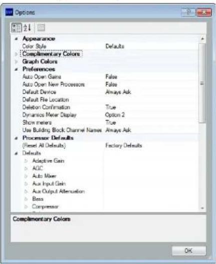
Figure 161. Options Dialog Box
Expansion Bus
With the Extron Expansion (EXP) port, two EXP-enabled devices can be connected for bidirectional streaming of up to 16 channels of audio. EXP inputs and outputs contain DSP (see Expansion and AT Inputs on page 53 and Expansion Outputs on page 65).
Connecting the EXP Ports
When connecting a DMP 128 Plus to another EXP-enabled device for EXP communication, one of the devices must be set as the primary unit. The primary unit serves as the master clock for all EXP audio communication. The other unit must be set as a secondary unit in order for a connection to be established.
There are two different procedures for setting up DMP 128 Plus for EXP communication. The first procedure describes how to set up a DMP 128 Plus non-AT model with another EXP-enabled non-AT device for EXP communication (see Connecting a DMP 128 Plus non-AT with Another EXP-Enabled non-AT Device below).
The second procedure describes how to set up a DMP 128 Plus AT model with another EXP-enabled non-AT device for EXP communication (see Connecting a DMP 128 Plus AT Device and an EXP-enabled non-AT Device on page 95 on the next page).
NOTE: Two DMP 128 Plus AT models cannot be connected via the EXP port because AT models can only be configured as a primary unit and cannot be set as a secondary unit. Instead, use the rear panel AT switch to connect the two devices over a Dante network (see Dante Controller on page 107).
Connecting a DMP 128 Plus non-AT with Another EXP-Enabled non-AT Device
The DMP 128 Plus can be connected to either a DTP CrossPoint or another DMP 128 Plus via EXP. The following procedure describes connecting a DMP 128 Plus non-AT with either a DTP CrossPoint or another DMP 128 Plus non-AT model.
- Connect live to the DMP 128 Plus.
NOTE: If connecting to DMP 128 Plus devices, decide which device will be set as primary unit and connect Live to that device.
-
Select Tools > Expansion Bus > Primary Unit.
-
Connect Live to the other DMP 128 Plus. If connecting a DTP CrossPoint, proceed to step 5.
-
Select Tools > Expansion Bus and ensure Secondary Unit is selected.
NOTE: If both devices are configured as primary or secondary, an EXP connection cannot be established.
-
Use a CAT 6 cable (such as the 1 foot cable included with the DMP 128 Plus) to connect the two rear panel EXP ports.
-
When the connection is established, the front panel EXP LED on the primary DMP 128 Plus lights steadily and the EXP LED on the secondary unit blinks rapidly.
NOTE: The DTP CrossPoint EXP LED is located on the rear panel next to the EXP port.
- Open the Tools menu from the DMP 128 Plus main workspace and view the Expansion Bus status software LED (see figure 162, ①). The LED lights green when there is a valid connection.
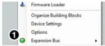
Figure 162. Expansion Bus Software LED
Connecting a DMP 128 Plus AT Device and an EXP-enabled non-AT Device
- Connect Live to the DMP 128 Plus AT.
- Select Tools > Expansion Bus > Use Extron Expansion Bus for channels 33-48 (see figure 163, ①). AT channels 33 through 48 now display as Expansion Inputs 1 through 8 and Expansion Inputs 9 through 16 in the main workspace (②).
NOTE: Dante channels 33 through 48 still appear in Dante controller, but are inactive when being used for Expansion Inputs 1 through 16.
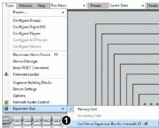
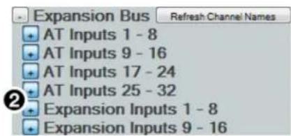
Figure 163. Enabling Expansion Inputs on DMP 128 Plus AT
- Connect Live to the DMP 128 Plus non-AT. If connecting a DTP CrossPoint, proceed to step 5.
- Select Tools > Expansion Bus and ensure Secondary Unit is selected.
NOTES:
- DMP 128 Plus AT models cannot be configured as secondary units. This means the DMP 128 Plus non-AT must be configured as a secondary unit.
-
If both devices are configured as primary, an EXP connection cannot be established.
-
Use a CAT 6 cable (such as the 1 foot cable included with the DMP 128 Plus) to connect the two rear panel EXP ports.
- When the connection is established, the front panel EXP LED on the primary unit lights steadily and the EXP LED on the secondary unit blinks rapidly.
NOTE: The DTP CrossPoint EXP LED is located on the rear panel next to the EXP port.
- Open the Tools menu from the DMP 128 Plus main workspace and view the Expansion Bus status software LED (see figure 164, ③). The LED lights green when there is a valid connection.
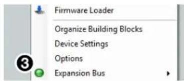
Figure 164. Expansion Bus Software LED
Phone Dialer
The Phone Dialer dialog box is used for DMP 128 Plus VoIP line configuration and testing. Click Tools>Phone Dialer to open the Phone Dialer dialog box.
NOTES:
- DSP Configurator must be connected Live to a DMP 128 Plus V model in order for the Phone Dialer dialog to be opened.
- VoIP lines must be registered with the call server via the DMP 128 Plus VoIP web page (see DMP 128 Plus VoIP Web Page on page 167).
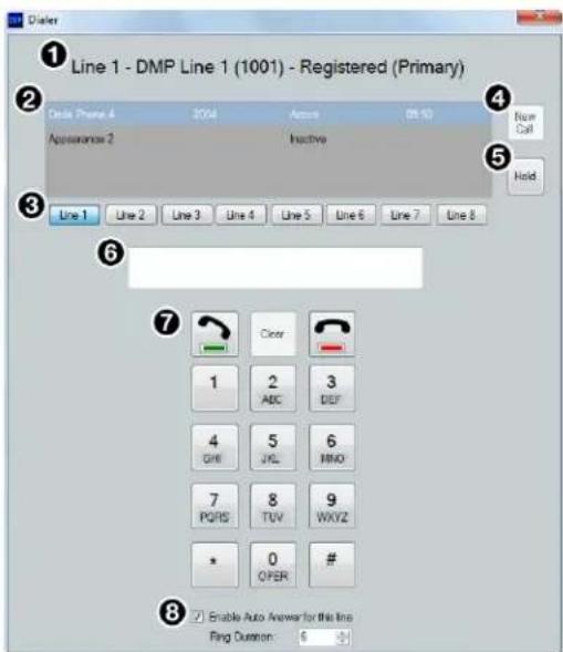
① Selected Line Information
② Appearance Window
③ Line Selection Buttons
④ New Call Button
⑤ Hold Button
⑥ Number Display
⑦ Dialer Keypad
⑧ Auto Answer Configuration
Figure 165. Phone Dialer Dialog Box
① Selected Line Information — Displays the line number, display name, extension number, and registration status of the selected line.
② Appearance Window — Displays line appearances configured in the DMP 128 Plus, line extension, call status, and call duration. Appearances must be selected to place or receive calls on a specific appearance.
③ Line Selection Buttons — Click these buttons to select a line and make calls or display corresponding line information. When a call is incoming on a specific line, the corresponding button flashes red.
4 New Call Button — Click this button after selecting a line and appearance to dial a number using the dialer keypad.
⑤ Hold Button — Click this button during a call to put the call on hold. Click it again to take a call off hold.
6 Number Field — Displays the number dialed with the dialer keypad. Alternatively, click this field and use the keyboard to dial a number.
⑦ Dialer Keypad — Contains software buttons for dialing when not in an active call and sending DTMF signals to the far end while in an active call. The green “off hook” button places a call after a number is dialed. The red “on hook” button ends a call on the selected line and appearance. The Clear button clears the number field.
⑧ Auto Answer Configuration — Contains a checkbox and Ring Duration field. Select the checkbox to enable auto answer on all appearances of the selected line (unchecked by default). Use the Ring Duration field to enter the amount of time in seconds before the line auto answers.
Placing a Call with the Phone Dialer
NOTE: VoIP lines must be registered with the call server via the DMP 128 Plus VoIP web page (see DMP 128 Plus VoIP Web Page on page 167) and assigned to an Aux input and output (see Aux Inputs on page 43).
- Select Tools>Phone Dialer. The Phone Dialer dialog opens.
- Select a line using the Line buttons (see figure 165, ③ on the previous page).
- Click New Call (4).
- Enter the desired number or extension using the keypad (7). Alternatively, click the number field (6) and type the desired number or extension using the keyboard.
- Click the green "off hook" button on the keypad (⑦).
- The appearance window (②) displays the status of the call.
- Click Hold to place the call on hold. Click Hold again to return to the call.
- Click the red "on hook" button to end the call.
Receiving a Call with the Phone Dialer
NOTE: VoIP lines must be registered with the call server via the DMP 128 Plus VoIP web page (see DMP 128 Plus VoIP Web Page on page 167) and assigned to an Aux input and output (see Aux Inputs on page 43).
- Select Tools>Phone Dialer. The Phone Dialer dialog opens.
- When a call is incoming, the corresponding Line button flashes red.
- Click the Line button with the incoming call.
- Highlight the appearance the call is on.
- Click the green "off hook" button on the keypad.
- Click the red "on hook" button to end the call.
Audio Control Panels (ACP)
Extron Audio Control Panels (ACP) are configurable control interfaces for use with the DMP 128 Plus. ACP panels connect to the rear panel ACP port of a DMP 128 Plus via a 4-pole 3.5 mm captive screw connector (see figure 2, F on page 5). Each ACP panel includes two ACP ports that support both power and communication between the DMP 128 Plus and the ACP panel. This section includes the following topics:
- ACP Panel Types
- Panel ID #
• ACP Panel Button Control Types
• Using Multiple ACP Panels - Configuration Examples
ACP Panel Types
ACP panels work by affecting group master controls, preset recall, and macro triggers, all of which must be configured on the DMP 128 Plus prior to configuring the ACP panels. The Configure ACPs dialog box presents a series of drop-down lists that populate with group masters, presets, and macros, according to the selections made.
When the Configure ACPs dialog is launched, the user is first asked to select a panel from the ACP Panel Type drop-down list. There are four models of ACP panel:
- ACP 100
- ACP 106 D
- ACP 106 EU
- ACP 106 MK
After a panel type is selected, the Configure ACPs dialog displays an image of the selected panel. The ACP 100 has six fully configurable buttons and a dedicated rotary volume knob. The ACP 106 style panels (ACP 106 D, 106 EU, and 106 MK) have six buttons. Two buttons are dedicated to mute off/mute on, two are dedicated to volume down/volume up, and the remaining two buttons are fully configurable.
All panels come with a default set of button labels. The ACP 100 also comes with additional button labels that can be used to relabel the buttons for alternate applications (see the ACP 100 Setup Guide for information on replacing buttons labels). Additional buttons for the ACP 106 style panels can be ordered from www.extron.com (see the ACP 106 D Setup Guide and ACP 106 EU/MK Setup Guide for information on replacing buttons).
Panel ID #
Panel ID numbers (ID #) are used to identify ACP panels connected to the DMP 128 Plus and are necessary for the panel to function. The ID # is set using the DIP switch assembly on the physical ACP panel. Once the panel ID has been set on the physical device, the ID is selected in the Configure ACPs dialog box when the panel is being configured in DSP Configurator (for information on how to set the panel ID #, see the corresponding ACP panel setup guide).
ACP Panel Button Control Types
Click on a button or rotary control within the panel image to select that button for configuration. When selected, the button or control will turn yellow to indicate that it is active for configuration, and the Configure ACPs dialog box will populate with a series of drop-down lists for that purpose. First, one of the following control types must be selected:
- Action-Fixed
• Action-Follow Selector - Selector-Vol/Mute
There are two basic control types: Action and Selector. Action controls can be either Action-Fixed or Action-Follow Selector. A button with dedicated functionality, such as a rotary knob or dedicated volume or mute buttons, can only be configured as an Action control type.
Action-Fixed
Buttons configured with the Action-Fixed control type perform an action that is tied to a fixed group, preset, or macro, and is not affected by or dependent on selections made on other buttons. When Action-Fixed is selected, the Configure ACPs dialog populates with a series of drop-down list selections shown in the table below. When a selection is made in the Action list, the Configure ACPs dialog then populates with subsequent selections.
| Action Select 1 Select 2 | LED Behavior | ||
| Group Mute On Mute Master | — Reflects Current State | ||
| Group Mute off Mute Master | — Reflects Current State | ||
| Group Mute Toggle Mute | Master — Reflects Current State | ||
| Group Volume Down Volume | Master — Reflects Current State | ||
| Group Volume Up | Volume Master — Reflects Current State | ||
| Group Vol Rotary (ACP 100 only) | Volume Master — Reflects Current State | ||
| Preset Recall | Preset | — Reflects Current State | |
| Preset Toggle | Preset 1 | Preset 2 | Lit press/Unlit release Toggles Lit/Unlit |
| Macro Trigger | Macro | — Lit press/Unlit release | |
| Macro Toggle | Macro 1 | Macro 2 | Lit press/Unlit release Toggles Lit/Unlit |
Figure 166. Action-Fixed Selection Table
Action-Follow Selector
A button configured with the Action-Follow Selector control type performs an action that is tied to a volume group or a mute group, but is dependent on a Selector-Vol/Mute button to define which group the button affects. The table below shows the drop-down list selections that are available when Action-Follow Selector is chosen as the control type.
| Action |
| Group Mute On |
| Group Mute Off |
| Group Mute Toggle |
| Group Volume Down |
| Group Volume Up |
| Group Vol Rotary (ACP 100 only) |
Figure 167. Action-Follow Selector Selection Table
Selector-Vol/Mute (Selector)
Buttons configured as a Selector-Vol/Mute define a gain or mute group. A Selector-Vol/Mute button acts as a modifier for Action-Follow Selector buttons or controls. For example, if an Action-Follow Selector button is configured to increase or decrease the volume of a group, a Selector button defines which gain group is affected by the volume increase or decrease. Two or more Selector buttons are necessary for Action-Follow Selector buttons to function properly.
Button Labels
Each button can be labeled to match the control type or function assigned to the button. In the Label text field on the right side of the Configure ACPs dialog box, type a name to aid in identifying the function of each button.
Using Multiple ACP Panels
The two ports on the back of an ACP panel support power from and communication with the host DMP 128 Plus. Up to eight ACP panels can be daisy-chained together for more demanding control needs.
NOTES:
- The DMP 128 Plus rear-panel ACP port provides 6 W of power.
- Use an Extron PS 1220EB power supply or Extron 12 V desktop power supply when additional power is required. Refer to the ACP panel setup guide for wiring details.
Configuration Examples
ACP panels can be configured to meet a wide variety of control needs. The following configuration procedures are examples of flexible configurations using the default buttons that ship with the ACP panels. The two configuration examples are covered:
• ACP 100 Configuration Example
• ACP 106 Style Configuration Example
Create the following gain and mute groups from the Configure Groups dialog box (see Configuring Groups on page 70).
- Mute and Gain groups for all microphone channels.
- Mute and Gain groups for all program channels.
- Mute and Gain groups for each individual program source.
- Mute group for all output attenuation blocks.
ACP 100 Configuration Example
- From the DMP 128 Plus main workspace in DSP Configurator, select Tools>Configure ACP Panels. The Configure ACPs dialog box opens.
- Select an empty tab from the top of the dialog box to build a new configuration (see figure 168, ① below).
- From the ACP Panel Type drop-down, select ACP 100 (2). The Configure ACPs dialog box populates with an ACP 100 graphic.
- From the ID # drop-down menu (③), select the ID number that corresponds with the bus ID set on the ACP 100 rear panel DIP switch assembly (see the ACP 100 Setup Guide for information on setting the bus ID).
- In the panel graphic on the left side of the Configure ACPs dialog box, the button labeled MIC is highlighted (yellow). When a button is highlighted, it is selected for configuration.
- From the Control Type drop-down, choose Selector-Vol/Mute (4). On the right side of the Configure ACPs dialog box, more configuration options appear.
a. From the Volume Master drop-down (5), select the gain group containing all microphone source channels. This group must be created from the Configure Groups dialog box before it can be selected from the drop-down (see Configuring Groups on page 70).
b. From the Mute Master drop-down (6), select the mute group containing all microphone source channels.
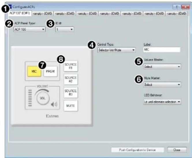
Figure 168. Starting ACP 100 Configuration
-
From the panel graphic on the left side of the dialog box, select the button labeled PRGM (see figure 168, ⑦ above).
-
From the Control Type drop-down, choose Selector-Vol/Mute (figure 168, 4).
a. From the Volume Master drop-down (5), select the gain group containing all program source channels.
b. From the Mute Master drop-down (6), select the gain group containing all program source channels.
-
From the panel graphic on the left side of the dialog box, select the button labeled Source #1 (8).
-
From the Control Type drop-down ④), choose Selector-Vol/Mute.
a. From the Volume Master drop-down ( 5 ), select the gain group containing just the first program source channels.
b. From the Mute Master drop-down (6), select the gain group containing just the first program source channels.
- Repeat steps 9 and 10 for additional individual program sources using the SOURCE #2 and SOURCE #3 buttons (up to three program sources can be controlled with this configuration).
- From the panel graphic on the left side of the dialog box, select the button labeled MUTE (see figure 169, ① below).
- From the Control Type drop-down (2), select either:
• Action-Fixed for the MUTE button to mute all output.
- Action-Follow Selector for the MUTE button to mute groups defined by a selector button.
If Action-Fixed was chosen:
a. From the Action drop-down ( 3 ), select Group Mute Toggle.
b. From the Mute Master drop-down (4), select the mute group containing all output channels.
c. From the LED Behavior drop-down (5), select Red reflects Mute On to turn the button red when mute is engaged, or White reflects Mute On to turn the button white when mute is engaged.
If Action-Follow Selector was chosen:
a. From the Action drop-down (6), select Group Mute Toggle.
b. From the LED Behavior drop-down (7), select Red reflects Mute On to turn the button red when mute is engaged, or White reflects Mute On to turn the button white when mute is engaged.
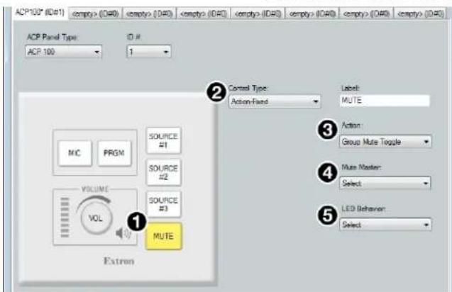
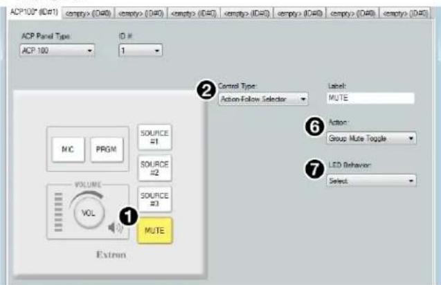
Figure 169. Mute Button Configuration
-
From the panel graphic on the left side of the dialog box, select the VOL knob (see figure 170, ① below).
-
From the Control Type drop-down ②), choose Action-Follow Selector.
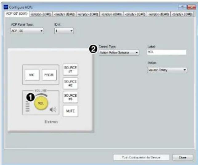
Figure 170. Rotary Volume Knob Configuration
The ACP 100 panel is now fully configured. From this point, either:
- Add additional ACP panel configurations.
- Save the ACP panel configuration to the DSP Configurator configuration file (see Saving and Pushing ACP Configurations on page 106).
- Push the configurations to the DMP 128 Plus (see Saving and Pushing ACP Configurations on page 106).
ACP 106 Style Configuration Example
- From the DMP 128 Plus main workspace in DSP Configurator, select Tools>Configure ACP Panels. The Configure ACPs dialog box opens.
- Select an empty tab from the top of the dialog box to build a new configuration (see figure 171, ① below).
- From the ACP Panel Type drop-down (②), select the ACP 106 model to be configured. The Configure ACPs dialog box populates with a graphic of the selected ACP 106.
- From the ID # drop-down (③), select the ID number that corresponds with the bus ID set on the ACP 106 DIP switch assembly (see the ACP 106 D Setup Guide or the ACP 106 EU/MK Setup Guide for information on setting the bus ID #).
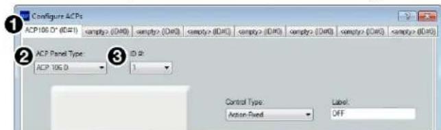
Figure 171. Selecting ACP 106 for Configuration
- In the panel graphic on the left side of the Configure ACPs dialog box, the mute button labeled OFF is highlighted (yellow). When a button is highlighted, it is selected for configuration.
- From the Control Type drop-down (see figure 172, ④ below), select either:
• Action-Fixed for the OFF button to unmute all output.
- Action-Follow Selector for the OFF button to unmute a group defined by a selector button.
If Action-Fixed was chosen:
a. From the Mute Master drop-down (5), select the mute group containing all output channels.
If Action-Follow Selector was chosen, the button is fully configured.
- From the panel graphic on the left side of the dialog box, select the mute button labeled ON (6).
- From the Control Type drop-down (⑦), select either:
• Action-Fixed for the ON button to mute all output.
- Action-Follow Selector for the ON button to mute a group defined by a selector button.
NOTE: The same control type chosen for the OFF mute button should be chosen for the ON mute button.
If Action-Fixed was chosen:
a. From the Mute Master drop-down (8), select the mute group containing all output channels.
If Action-Follow Selector was chosen, the button is fully configured.
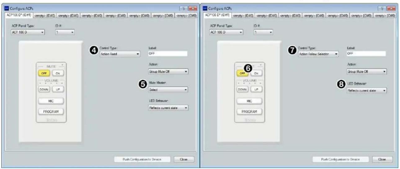
Figure 172. Configuring Mute Off and Mute On Buttons
-
From the panel graphic on the left side of the dialog box, select the volume button labeled DOWN (see figure 173, ⑨ below).
-
From the Control Type drop-down, choose Action-Follow Selector (10).
-
From the panel graphic on the left side of the dialog box, select the volume button labeled UP (1).
-
From the Control Type drop-down, choose Action-Follow Selector (10).
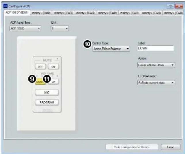
Figure 173. Configuring Volume Down and Volume Up
-
From the panel graphic on the left side of the dialog box, select the button labeled MIC (see figure 174, 13 on the next page).
-
From the Control Type drop-down (14), choose Selector-Vol/Mute.
a. From the Volume Master drop-down (15), select the gain group containing all microphone source channels. This group must be created from the Configure Groups dialog box before it can be selected from the drop-down (see Managing Devices in Device Manager on page 83).
b. From the Mute Master drop-down (16), select the mute group containing all microphone source channels.
- From the panel graphic on the left side of the dialog box, select the button labeled PROGRAM (see figure 174, 17 below).
- From the Control Type drop-down (18), choose Selector-Vol/Mute.
a. From the Volume Master drop-down (19), select the gain group containing all program source channels.
b. From the Mute Master drop-down (20), select the gain group containing all program source channels.
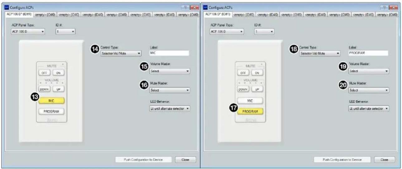
Figure 174. Configuring Mic and Program Selector Buttons
The ACP 106 panel is now fully configured. From this point, either:
- Add additional ACP panel configurations.
- Save the ACP panel configuration to the DSP Configurator configuration file (see Saving and Pushing ACP Configurations below).
- Push the configurations to the DMP 128 Plus (see Saving and Pushing ACP Configurations below).
Saving and Pushing ACP Configurations
- Configure up to four ACP panels.
- Close the Configure ACPs dialog box. Button configurations remain after the dialog box is closed.
- Save the configuration file. ACP configurations are saved with the configuration file.
- Connect Live to a DMP 128 Plus via a LAN (TCP/IP) connection.
NOTE: The host computer must be connected to the DMP 128 Plus LAN port in order to push ACP configurations to the device.
-
Select Tools > Configure ACP Panels. The Configure ACPs dialog box opens.
-
Click Push Configuration to Device. Configurations from all four tabs in the Configure ACPs dialog box are pushed to the DMP 128 Plus.
Dante Controller
This section describes the DMP 128 Plus AT network installation, configuration, and control using Dante Controller for Windows and covers the following topics:
- Overview
• Downloading and Installing Dante Controller - Configuring the DMP 128 Plus AT in Dante Controller
• Physical Dante Network Setup
• Dante Controller Operation
• Dante Routing Operation
• Dante Troubleshooting
Overview
DMP 128 Plus AT devices (DMP 128 Plus AT, C AT, and C V AT) use Dante technology by Audinate to provide high performance digital audio networking over standard TCP/IP networks. The Dante Controller software application is used to route audio on the network. Dante allows audio channels to be transported across a switched Ethernet data network while meeting the quality requirements of professional audio.
Up to 24 channels can be transmitted from the DMP 128 Plus AT to the Dante network and up to 48 channels can be received by the DMP 128 Plus AT from the Dante network. AT inputs 33 through 48 can be used to facilitate EXP bus communication (see Connecting a DMP 128 Plus AT Device and an EXP-enabled non-AT Device on page 95).
Audio signals are converted by DMP 128 Plus AT devices, processed and routed to the AT bus, and transmitted onto the Dante network. Audinate recommends the Dante audio network be kept separate from other networks. However, the audio network can be shared with control traffic or unrelated data traffic. Audio channels can be unicast or multicast to make the best use of available bandwidth.
Downloading and Installing Dante Controller
Dante Controller from Audinate is required to route transmitters and receivers and can be used to configure Dante settings and monitor performance. Install Dante Controller on a PC running Microsoft® Windows® 7 or newer. For full details about computer requirements and to download the software, see the Dante Controller product page at www.extron.com.
To download Dante Controller:
- On the Extron Electronics web page, click the Download tab (see figure 175, ① below). The Download page opens.
- On the left sidebar, click the Dante Controller link (②). The Dante Controller page opens (see figure 176 on the next page).
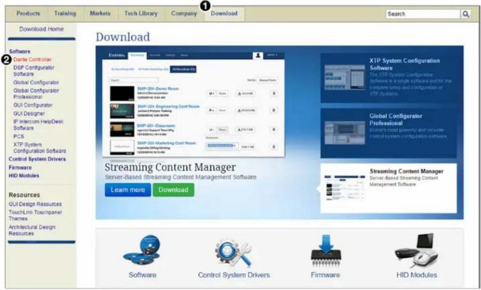
Figure 175. Accessing the Dante Controller Download Page
- On the Dante Controller page, click Download (see figure 176, ① below). The Download Center page opens.
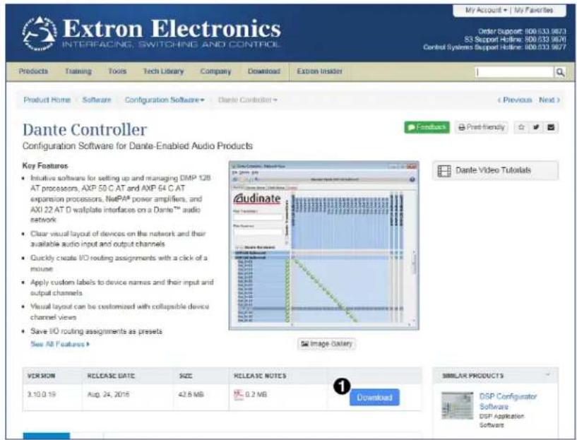
Figure 176. Dante Controller Page
- On the Download Center page, click the Download button and follow the prompts to download or run the Dante Controller installer file. If you choose to save the file for later installation, note the location.
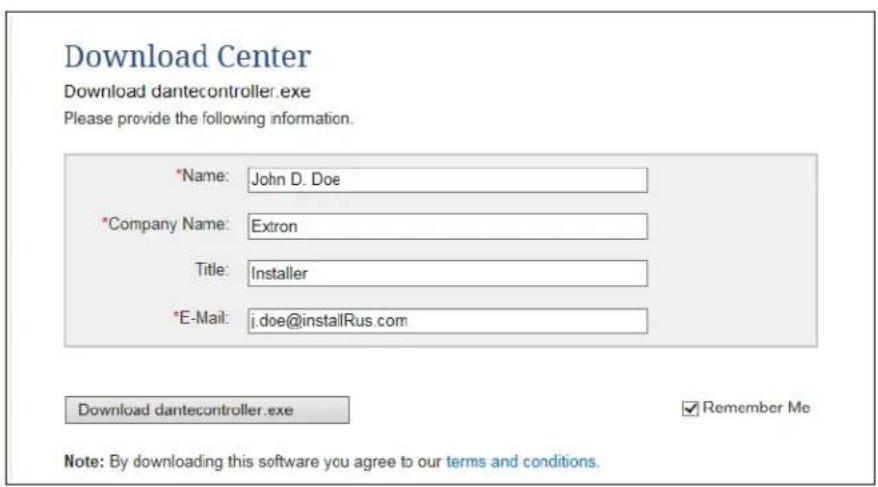
Figure 177. Download Center, Dante Controller File
- If you choose to run the file, follow all prompts. If you saved the file, click the saved file to begin installation when ready.
The installed Dante Controller program files are saved in:
C:\Program Files (x86)\Audinate\Dante Controller\DanteController.exe.
Configuring the DMP 128 Plus AT in Dante Controller
Use a standard Ethernet cable to connect the DMP 128 Plus AT to a Dante network via the rear panel AT port (see figure 2, ① on page 5) and power the device.
Device Name
Multiple devices on the same Dante network can present difficulty in identifying individual devices. To avoid confusion and difficulty, ensure the following steps are taken:
- Connect devices to the Dante network one at a time.
- Rename each device before making audio connections in Dante Controller.
- Rename each device with a unique and meaningful identifier.
- Rename each device before the next device is connected to the Dante network.
ATTENTION: It is essential that a Dante device be named before audio subscriptions with other devices are established. Existing subscriptions are removed when a device is renamed.
In Dante Controller, a device can be renamed to identify the device on the audio network. The default device name of the DMP 128 Plus AT consists of the model name, followed by the last six characters of the Dante interface MAC address (for example, DMP128P-0ee8ee). In addition to renaming the device, individual Transmitter (Tx) and Receiver (Rx) channels can be renamed.
The Dante device name must be set before making any connections to other devices on the Dante network. Renaming a device after making connections removes existing connections to and from that device. Refer to Renaming the DMP 128 Plus AT in Dante Controller on the next page for renaming procedure.
Receiver and Transmitter Names
In addition to renaming a device, individual transmitter and receiver channels can be renamed in Dante Controller. Rename transmitter and receiver channels to reflect the location of the device or the purpose of the transmitter or receiver. Ensure transmitter and receiver channels are renamed before making audio connections between devices. Refer to Renaming a Receiver or Transmitter on page 113 for renaming procedure.
Dante Controller Naming Conventions
- Device names follow Domain Name System (DNS) hostname rules. Legal characters are A-Z, a-z, 0-9, and hyphen (-). Names must begin with a letter and cannot end with a hyphen (-).
- Dante Tx and Rx channel names (also known as labels) can be up to 31 characters in length. Label names are not case-sensitive. For example, “ANALOG OUT-1” and “analog out-1” are recognized as the same name. Unicode and non-roman characters are not supported.
- Tx and Rx channel labels can use any character except equals (=), period (.), or @.
- Tx and Rx channel labels must be unique on a device but do not need to be unique on the network.
Renaming the DMP 128 Plus AT in Dante Controller
NOTE: Dante device naming can also be done via DSP Configurator (see Dante Device on page 92).
- Ensure that the control computer and a single DMP 128 Plus AT are connected to the same network.
- From the control computer Start menu select:
All Programs > Audinate > Dante Controller > Dante Controller
- The Dante Controller - Network View screen opens. All Dante devices on the network are discovered and listed.
- From the Device menu, select Device View or press
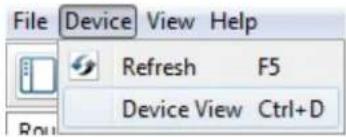
Figure 178. Opening Device View
- The Dante Controller - Device View dialog opens. Select the device being configured from the (Select a Dante Device...) drop-down list (see figure 179, ① below).

Figure 179. Device View and Select a Dante Device Drop-Down
NOTES:
- If there are multiple DMP 128 Plus AT devices connected to the network that have not been renamed, obtain the Dante interface media access code (MAC) address of the desired device from the white label on the rear panel of the device in order to identify it in Dante Controller.
- There are two MAC addresses listed on the rear panel of a DMP 128 Plus AT, one for the LAN port and one for the Dante interface. The Dante interface MAC address is listed beneath the LAN port MAC address.
The Device View dialog populates with the selected DMP 128 Plus AT information.
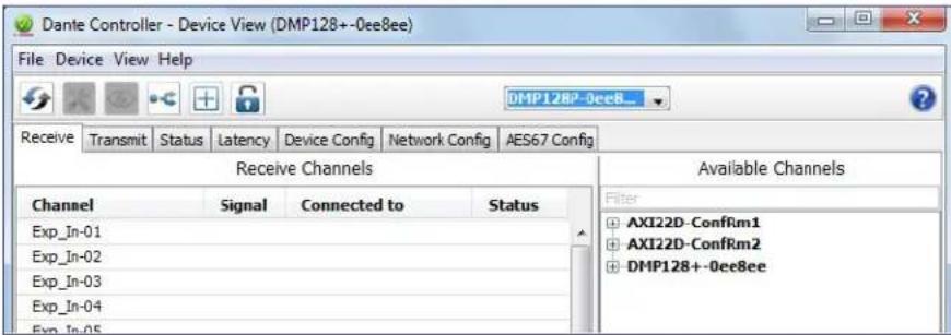
Figure 180. Populated Device View Dialog Box
- Click the Device Config tab (see figure 181, ① below) to open the Device Config page.
- In the Rename Device panel, enter the new name of the device in the text field. No spaces are allowed in the name. Names should be significant identifiers. For example, enter DMP128Plus-MainRack (②).
- Click Apply ( ③). A confirmation prompt opens.
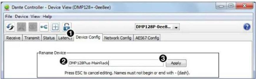
Figure 181. Device Config Dialog, Rename Device
- Click Yes (4) to confirm the new name, then close the Device Configuration dialog box. The new name is written to the Dante interface of the DMP 128 Plus AT. Repeat as necessary for all devices.
NOTE: The device name assigned in Dante Controller only applies to the Dante interface and does not affect the device name recognized in DSP Configurator.
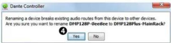
Figure 182. Rename Device Confirmation Dialog Box
Renaming a Receiver or Transmitter
In addition to renaming devices, individual receiver and transmitter channels can be renamed in Dante Controller. To better organize the various receivers and transmitters, it is recommended each receiver and each transmitter be named using a description of the device they belong to, the location of the device, or the purpose of the receiver or transmitter.
To view the receiver or transmitter channels in Dante Controller, click the + sign next to the receiver or transmitter device name to expand it. The + sign becomes a - sign when the device is expanded (see figure 183, ①).
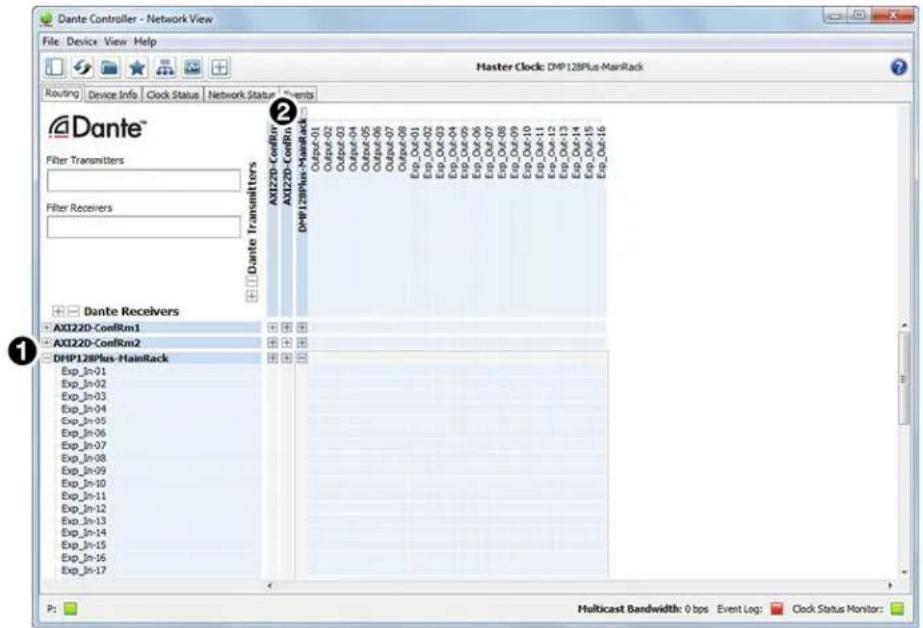
Figure 183. Expanded Device View — Input and Output Names
TIP: To simplify setup and operation of large matrix systems, rename the receiver and transmitter channels to better indicate the source at the transmitters or receivers.
Renaming a Receiver
The default names shown in the Dante Receivers column are extracted from the Dante interface of the connected device (see figure 183, ①). The DMP 128 Plus AT receivers are labelled EXP_In-01 through EXP_In-48 because the DMP 128 Plus AT can receive signal at the 48 EXP inputs. Follow the instructions on the next page to rename a receiver.
To rename a DMP 128 Plus AT receiver:
- From the Device menu on the Network View screen, select Device View, or press
- From the (Select a Dante Device...) drop-down menu, select the name of the desired DMP 128 Plus AT (see figure 184, ① below).
- On the Device View screen, select the Receive tab (2).
- Click on the name of the receiver to be renamed. The name becomes a text box with a cursor (③).
- Enter the new name (up to 31 characters) using any combination of letters, numbers, and special characters except for @, =, and . (period).
- Press
on the keyboard to confirm the name, or click another channel text box. - Repeat steps 4 through 6 to rename additional receiver channels.
- When finished renaming receivers, close the Device View dialog box.
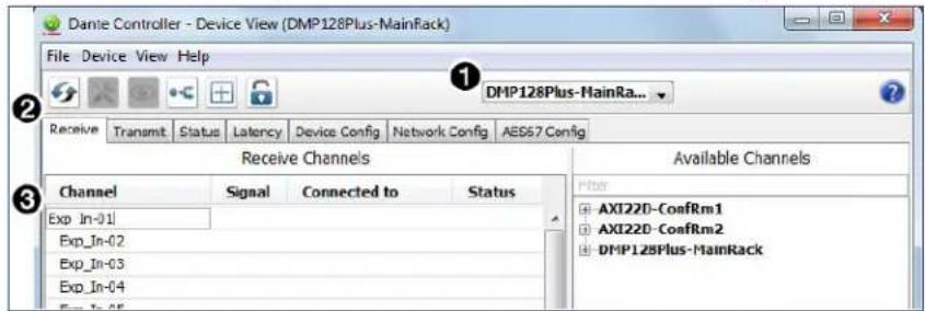
Figure 184. Device View Screen — Renaming a Receiver
Renaming a Transmitter
The default names shown in the Dante Transmitters column are extracted from the Dante interface of the connected device (see figure 183, ② on the previous page). The first set of DMP 128 Plus AT transmitters is labelled Output-01 through Output-08 because the DMP 128 Plus AT can transmit signal routed to the analog outputs to the Dante network. The second set of DMP 128 Plus AT transmitters is labelled EXP-Out-01 through Exp_Out-16 because the DMP 128 Plus AT can transmit signal routed to the EXP outputs to the Dante network. Follow the instructions on the next page to rename a transmitter.
To rename a DMP 128 Plus AT transmitter:
- Select Device View from the Device menu on the Network View screen or press
- From the (Select a Dante Device...) drop-down menu, select the name of the DMP 128 Plus AT (see figure 185, ① below).
- On the Device View screen, select the Transmit tab (2).
- Click in the Channel Label column to the right of the name of the transmitter being renamed. A text box and cursor appear (3).
- Enter a new name (up to 31 characters) using any combination of letters, numbers, and special characters except for @, =, and . (period).
- Press
on the keyboard to confirm the name, or click another label text box. - Repeat steps 4 through 6 to rename additional transmitter channels.
- When finished renaming transmitters, close the Device View dialog box.
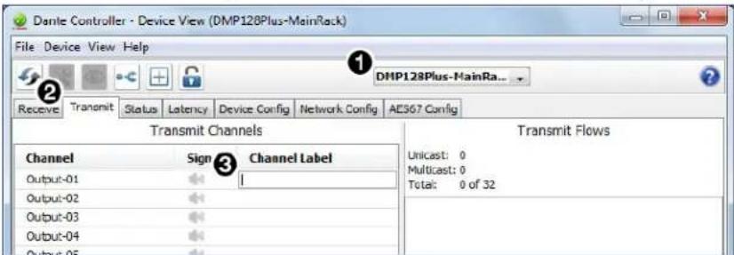
Figure 185. Device View Screen — Renaming a Transmitter
Finding a Dante Device IP Address
To find the IP address of a Dante device, the name of the device is needed (see Renaming the DMP 128 Plus AT in Dante Controller on page 111).
NOTE: If the DMP 128 Plus AT has not been renamed, its default name consists of the product name followed by a hyphen, plus the last 6 digits of the device MAC address (for example, DMP128P-0ee8ee).
- Open Dante Controller.
- On the Dante Controller-Network View screen, click the Device Info tab (see figure 186, ① below).
- On the Device Info page, locate the name of the DMP 128 Plus AT in the Device Name column (②). The IP address is located in the Primary Address column (③). In the example below, the IP address for the connected DMP 128 Plus AT is 192.168.11.120.
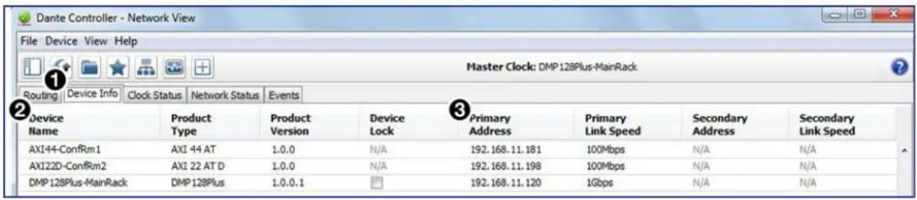
Figure 186. Device Info Page
Physical Dante Network Setup
A physical network is required to share Dante audio channels between Dante-enabled devices like the DMP 128 Plus AT. Other Dante-enabled devices must be on the same physical network in order to communicate via Dante. There are two types of network topology that can be used to create a physical Dante network.
• Star Topology • Daisy Chain Topology
Star network topology has one DMP 128 Plus AT as the central unit which is directly connected to up to 3 other units. A larger network switch can be used in place of a central DMP 128 Plus AT, allowing more than four total units to be connected in the star topology.
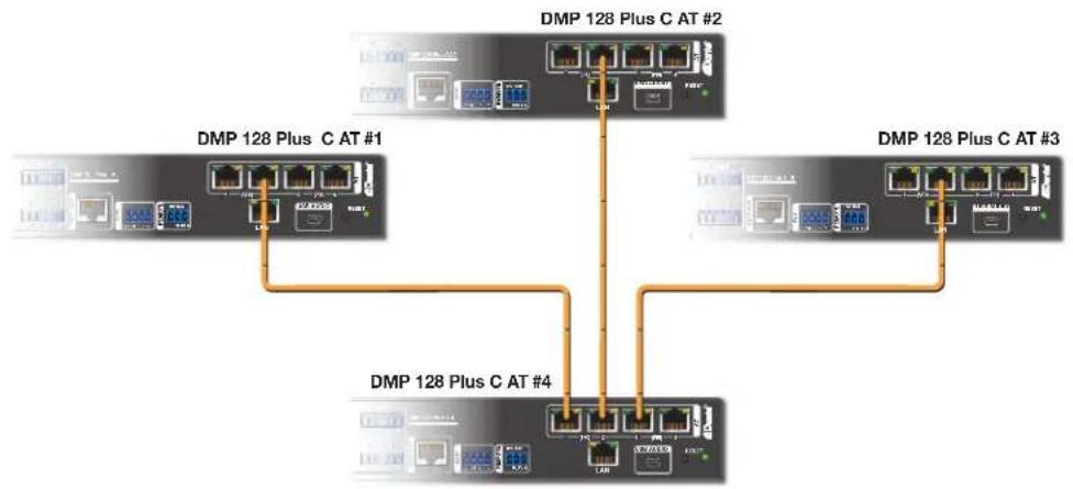
flowchart
graph TD
    A["Network Port 1"] -->|Ethernet Interface| B["DMP 128 Plus C AT #1"]
    A -->|Ethernet Interface| C["DMP 128 Plus C AT #2"]
    A -->|Ethernet Interface| D["DMP 128 Plus C AT #3"]
    A -->|Ethernet Interface| E["DMP 128 Plus C AT #4"]
    B --> F["Terminal"]
    C --> G["Terminal"]
    D --> H["Terminal"]
    E --> I["Terminal"]
Figure 187. Star Network Topology
Daisy Chain topology has DMP 128 Plus AT units connected in succession.

Figure 188. Daisy Chain Network Topology
Hybrid versions combining the star and daisy chain topologies can be used, but a ring topology or any topology that creates a duplicate connection causes a failure in Dante Controller. Redundant connections are possible using the primary and secondary port interface structure (see Redundant Configuration on the next page).
Redundant Configuration
In redundant mode, the 4-port AT switch acts as two separate 2-port switches that duplicate audio traffic. Ports 3 and 4 are marked (PRI) for primary while ports 1 and 2 are marked (SEC) for secondary (see figure 189 below). Primary and secondary switches cannot be connected together anywhere in the audio network. Redundant configuration can be enabled using Dante Controller or DSP Configurator.
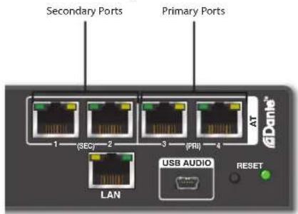
Figure 189. Primary and Secondary AT Ports
To configure the DMP 128 Plus in redundant mode using Dante Controller:
- Open Dante Controller.
- Press
-
Select the desired DMP 128 Plus AT from the (Choose a Dante Device...) drop-down menu (see figure 190, ① below).
-
Select the Network Config tab (②).
-
From the Dante Redundancy panel, use the drop-down to select Redundant (3).
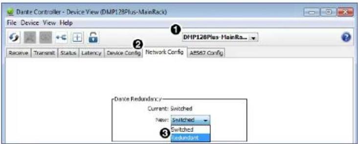
Figure 190. Redundant Mode Configuration in Dante Controller
To configure the DMP 128 Plus AT in redundant mode using DSP Configurator:
- Use DSP Configurator to connect to the DMP 128 Plus AT in Live mode (see Live and Emulate Panel on page 18).
- Select Tools > Device Settings.
- In the Device Settings dialog box, use the right navigation arrow (☐) to navigate to and select the Dante Device tab (see figure 191, ① below).
- Select Enable Redundant Mode (②).
- Select DHCP or Static IP and enter a valid redundancy network configuration (③).
- Click Apply ( 4).
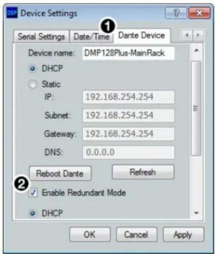
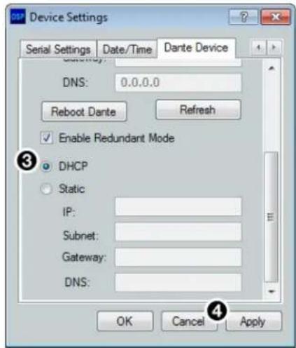
Figure 191. Redundant Mode Configuration in DSP Configurator
Dante Controller Operation
Dante Transmitters and Receivers
A Dante network is comprised of transmitters that output digital audio onto the Dante network and receivers that receive digital audio input from the Dante network.
• Transmitters output digital audio from the device onto the audio network.
- Receivers take in digital audio from the audio network into the device.
DMP 128 Plus AT Transmitters and Receivers
In the DMP 128 Plus AT, the line output and EXP output channels are Dante transmitters because their audio output is transmitted onto the Dante network. Routing an analog output to the Dante network allows the signal to be output on both analog and Dante simultaneously, the same is true for the EXP outputs.
The DMP 128 Plus AT EXP input channels are Dante receivers because they receive digital audio signal from the Dante network that can then be routed and mixed into the DMP 128 Plus AT mix matrix.
Dante Routing Operation
Dante Controller is used for all network signal routing of transmitters and receivers for Dante-enabled devices. The DMP 128 Plus AT transmitters and receivers are available in Dante Controller for routing to other Dante devices (see Dante Transmitters and Receivers on the previous page).
Routing Devices
After the DMP 128 Plus AT is configured, the channels can be routed to the other Dante devices on the audio network. Channels transmitted to the network or received from the network are routed using the Dante Controller Routing tab on the Network View page (see figure 192 on the next page). The transmitters, listed horizontally along the top of the screen, and the receivers, listed vertically down the left side, form a matrix whose intersections are the connection points between the receivers and transmitters.
- To make a receiver-to-transmitter connection, click once on an intersection.
- To remove a connection, click on the icon at the intersection.
One of the following icons appears at each connection intersection, indicating the status of both the transmitter and receiver channels and the connections (subscriptions):
| Icon D | Description |
| Indicates an active subscription. | |
| Indicates subscription is in progress. | |
| Indicates a pending subscription. | |
| Indicates a broken subscription. | |
| Indicates the transmitting device has been removed from the network or is switched off. |
See the Dante Controller User Guide, available at www.audinate.com, for additional information.
Creating Subscriptions Between Transmitters and Receivers
- Ensure the control computer and DMP 128 Plus AT are connected to the same network.
- From the start menu select:
All Programs > Audinate > Dante Controller > Dante Controller
The Dante Controller - Network View screen opens (see figure 192 on the next page).
Dante Controller auto-discovers Dante devices on the network and advertises itself to allow other Dante-enabled devices to communicate with it. Transmitters connect to receivers using the subscription matrix.
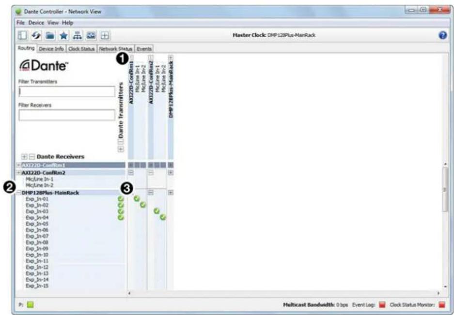
Figure 192. Routing Tab of Network View Screen
- To show the transmitters of a Dante device, click the + box next to the desired device in the Dante Transmitters panel, such as AXI22D-ConfRm1 (see figure 192, ① above). The + changes to a - sign when the device expands.
- To show the receivers of a Dante device, click the + box next to the desired device in the Dante Receivers panel, such as DMP128Plus-MainRack (2).
- Click the intersection of the desired subscription between a transmitter and a receiver (3).
Example: The mic/line input transmitters of the AXI22D-ConfRm1 and AXI22D-ConfRm2 are routed to the EXP input receivers of the DMP128Plus-MainRack.
A check mark at the intersection indicates the subscription is made. A check mark also appears next to the receiver channel.
NOTE: A receiver can connect to only one transmitter. A transmitter can connect to multiple receivers.
Disconnecting Inputs from Outputs
To undo routing, click the junction again to disconnect the receiver from the transmitter.
NOTE: After making changes to Dante network routing such as subscriptions, device names, or channel labels, wait at least 5 seconds before disconnecting or powering down the devices. This ensures that the new information is properly saved to those devices. Device level configuration such as sample rates, latency, and clock settings are saved instantly.
Dante Troubleshooting
The most common Dante troubleshooting issues occur when devices are not discovered by Dante Controller or when routing is not successful. Both issues occur when software is not able to properly discover devices operating on the Dante network.
Before moving into more difficult troubleshooting, shut down Dante Controller and reseat the Ethernet cable connecting the PC to the Dante network and restart Dante Controller. This can be enough for the software to reacquire the Dante network.
If the problem persists, perform the following troubleshooting procedures in the order listed.
Simplifying the Network for Troubleshooting
If further troubleshooting of Dante Controller is necessary, begin by simplifying the network:
- Bypass network switches by connecting two Dante-compatible units, such as a DMP 128 Plus AT and an AXI 44 AT, via their AT ports.
- Connect the PC to an unused AT port with an Ethernet cable.
- Use Dante Controller to check if the issue was resolved before moving on to network interface troubleshooting.
- If the issue is resolved, add connections and hardware one at a time, checking for proper operation after each addition, until the point of failure is discovered (typically a bad cable or invalid redundant configuration).
Troubleshooting the Network Interface
If the issue is still present, continue to diagnose the PC network connections as described below. Check Dante Controller after each step to see if the problem is resolved.
- Click the Choose a Dante Interface icon (see figure 193, ① below). The Configure Dante Interfaces dialog box opens.
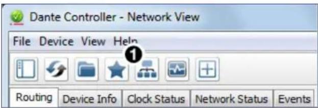
Figure 193. Choose a Dante Interface Icon
Be certain the correct LAN connection is selected (the PC LAN port that is physically connected to the AT network) and note the IP address.
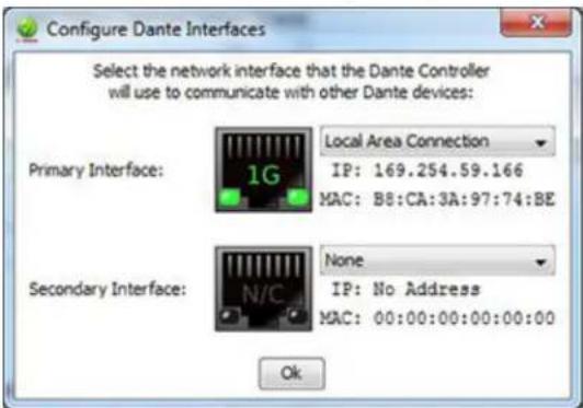
Figure 194. Configure Dante Interfaces Dialog Box
- If it is on, turn off the PC wireless adapter. Disable all connections except the LAN port connected to the Dante network (verify this is the correct port by checking the IP address shown in the Configure Dante Interfaces dialog).
- Turn off all anti-virus and firewall software on the computer.
- Enable DHCP on the remaining network connection. This forces the computer to acquire an IP address from the Dante interface.
NOTE: A DHCP server must be on the network for DHCP to function correctly.
Restarting Dante Controller
If subscriptions or normal operation cannot be restored, restart Dante Controller software. To access the Dante Controller Help file, do any of the following:
- Click the Help icon in the upper-right corner of the Network View screen (see figure 195, ① below).
- Select Help, then Online Help or Offline Help from the menu (2).
- Press the
key on the computer keyboard for online help or
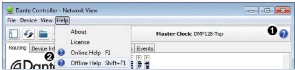
Figure 195. Accessing the Dante Help File
Remote Communication and Control
This section describes how to control the DMP 128 Plus with SIS programming and covers the following topics:
- Connection Options
• Host-to-Device Communications
• Using the Command and Response Tables
• Command and Response Table for Basic SIS Commands
• Command and Response Table for DSP SIS Commands
• Command and Response Table for VoIP SIS Commands
• Object ID (OID) Number Tables
Connection Options
The DMP 128 Plus Digital Matrix Processor can be remotely connected via a host computer or other device (such as a control system) attached to the rear panel RS-232 port or LAN port, or the front panel USB Config port.
The DMP 128 Plus can be set up and controlled using SIS commands or DSP Configurator software (see Installation on page 4 for pin assignments and details on the configuration and control port connections. For information on DSP Configurator, see DSP Configurator Software on page 10).
SIS commands can be executed using the Extron DataViewer application available from www.extron.com. The host computer issuing the commands can be connected via the following connections:
• RS-232 Port on the next page
• LAN Port on the next page
• USB Config Port on page 125
RS-232 Port
The DMP 128 Plus has a serial port that can be connected to a host device such as a computer running either the DataViewer or HyperTerminal utilities. The port makes serial control of the DMP 128 Plus possible.
The DMP 128 Plus uses the following RS-232 protocols:
• 38400 baud
- No parity
- 1 stop bit
- 8 data bits - No flow control
NOTES:
- The rear panel configuration port requires 38400 baud communication. This speed is higher than most other Extron products. The DMP 128 Plus control software automatically sets the connection for the appropriate speed. When using DataViewer or similar application, make sure the host PC or control system is set for 38400 baud.
- See Rear Panel Features and Cabling on page 5 for additional details on connecting to the RS-232 port.
LAN Port
The DMP 128 Plus can be connected to an Ethernet LAN or WAN. Communication between the device and the controlling device is via Telnet (a TCP socket using port 23). The Telnet port can be changed, if necessary, via SIS. This connection makes SIS control of the device possible using a computer connected to the same LAN or WAN. The SIS commands and behavior are identical to the commands and behavior the product exhibits when communicating by serial port or USB.
The DMP 128 Plus LAN port defaults are as follows:
| IP Address Subnet | Mask Default Gateway | DHCP | |
| 192.168.254.254 255.255.255.0 0.0.0.0 OFF | |||
The Ethernet cable can be terminated as a straight-through cable or a crossover cable and must be properly terminated for your application.
• Crossover cable — Direct connection between the computer and the DMP 128 Plus.
- Straight-through (Patch) cable — Connection of the DMP 128 Plus to an Ethernet LAN.
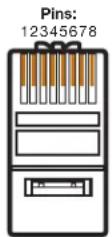
RJ-45
Connector
| Crossover Cable(for direct connection to a PC) | |||
| Pin | End 1Wire Color | Pin | End 2Wire Color |
| 1 | white-orange | 1 | white-green |
| 2 | orange | 2 | green |
| 3 | white-green | 3 | white-orange |
| 4 | blue | 4 | blue |
| 5 | white-blue | 5 | white-blue |
| 6 | green | 6 | orange |
| 7 | white-brown | 7 | white-brown |
| 8 | brown | 8 | brown |
T568A T568B
A cable that is wired as TIA/EIA T568A at one end and T568B at the other (Tx and Rx pairs reversed) is a "crossover" cable.
| Straight-through Cable(for connection to a switch, hub, or router) | |||
| Pin | End 1 Wire Color | Pin | End 2 Wire Color |
| 1 | white-orange | 1 | white-orange |
| 2 | orange | 2 | orange |
| 3 | white-green | 3 | white-green |
| 4 | blue | 4 | blue |
| 5 | white-blue | 5 | white-blue |
| 6 | green | 6 | green |
| 7 | white-brown | 7 | white-brown |
| 8 | brown | 8 | brown |
T568B
A cable wired the same at both ends is called a "straight-through" cable because no pin/pair assignments are swapped.
Figure 196. RJ-45 Ethernet Connector Pin Assignments
Establishing a Network Connection via LAN
- Open a TCP socket to port 23 using the DMP 128 Plus IP address.
NOTE: If the local system administrators have not changed the value, the factory specified default, 192.168.254.254, is the correct value for this field.
- The DMP 128 Plus responds with a copyright message including the date, the name of the product, firmware version, part number, and the current date/time.
- If the device is password protected, enter the appropriate administrator or user password.
a. If the password is accepted, the device responds with Login User or Login Administrator.
b. If the password is not accepted, the Password prompt reappears.
NOTES:
- The Ethernet link times out after a designated period of time of no communications. By default, the timeout value is set to 5 minutes and can be changed (see Set global IP port timeout on page 129).
- Extron recommends leaving the default timeout at 5 minutes and periodically issuing the Query (Q) command to keep the connection active. If there are long idle periods, disconnect the socket and reopen the connection when another command must be sent.
USB Config Port
The DMP 128 Plus has a front panel USB port that can be connected to a computer as a host device running either the HyperTerminal or DataViewer utilities for control of the device. Once a connection is established, SIS programming can begin (see Host-to-Device Communications on the next page).
Verbose Modes
Telnet connections are used to monitor changes that occur, such as commands from other Telnet sockets or a serial port. For a Telnet session to receive change notices, the Telnet session must be in verbose mode 1 or 3 (see Set verbose mode on page 132). In verbose mode 1 or 3, the Telnet socket reports changes in messages that resemble SIS command responses.
Tagged and Untagged Responses
When a query command is sent in verbose mode 0 or 1, only the “untagged” value is returned. When a query command is sent in other verbose modes, the response is “tagged” and resembles the response to a set command.
Example: The gain query command EscG40000AU← is sent. The following responses appear depending on the verbose mode:
- Untagged (verbose 0 or 1): 626←, just the gain value with no other information.
- Tagged (verbose 2 or 3): DsG40000*626←, the type of query sent, the OID queried, and the gain value.
NOTE: All query responses listed in this guide are untagged.
Host-to-Device Communications
The commands listed in the following tables perform the same functions, but are encoded differently to accommodate the requirements of each Telnet or browser port.
DMP 128 Plus-initiated Messages
The DMP 128 Plus initiates messages under specific conditions. No response is required for the host. The DMP 128 Plus-initiated messages are listed below.
Copyright Message
The DMP 128 Plus initiates the following copyright message when it is first powered on or when a connection via IP is established:
(c) Copyright 2016–2018, Extron Electronics, DMP 128 Plus {model}, Vn.nn, 60-nnnn-nn
Day, DD MMM YYYY HH:MM:SS
- Vn.nn is the firmware version number.
• {model} is the full model name. DMP 128 Plus C, for example. - 60-nnnn-nn is the DMP 128 Plus part number.
The DMP 128 Plus sends the boot and copyright messages under the following circumstances:
- If the DMP 128 Plus is off and RS-232 connection is already set up (the PC is cabled to the DMP 128 Plus and a serial communication program such as DataViewer is open), the connected unit sends these messages via RS-232 when first powered on.
- The DMP 128 Plus sends the boot and copyright messages when a Telnet connection to the DMP 128 Plus is opened via Telnet, but not via RS-232. If using a Telnet connection, the copyright message, date, and time may be followed by a password prompt.
Password Prompt
The ←Password prompt requires an administrator or user password followed by a carriage return. The prompt is repeated if the incorrect password is entered.
If the correct password is entered, the unit responds with ←Login Administrator← or ←Login User← depending on the password entered. If passwords are the same for both administrator and user, the unit will default to administrator privileges.
Using the Command and Response Tables
SIS commands consist of a string (one or more characters per command field). No special characters are required to begin or end a command sequence. When the DMP 128 Plus determines a command is valid, it executes the command and sends a response to the host device. All responses end with a carriage return and a line feed, signaling the end of the response character string.
When programming, certain characters are more conveniently represented by their hexadecimal rather than ASCII values. The table below shows the hexadecimal equivalent of each ASCII character:
| ASCII to HEX Conversion Table | Esc 1B | CR ∅D | LF ∅A | |||||||
| Space | 20 | ! | 21 | “ | 22 | # | 23 | $ 24 | % 25 | & 26 |
| ( | 28 | ) | 29 | * | 2A | + | 2B | , 2C | - 2D | • 2E |
| ∅ | 30 | 1 | 31 | 2 | 32 | 3 | 33 | 4 34 | 5 35 | 6 36 |
| 8 | 38 | 9 | 39 | : | 3A | ; | 3B | < 3C | = 3D | > 3E |
| @ | 40 | A | 41 | B | 42 | C | 43 | D 44 | E 45 | F 46 |
| H | 48 | I | 49 | J | 4A | K | 4B | L 4C | M 4D | N 4E |
| P | 50 | Q | 51 | R | 52 | S | 53 | T 54 | U 55 | V 56 |
| X | 58 | Y | 59 | Z | 5A | [ | 5B | \ 5C] | ] 5D | ^ 5E |
| 、 | 60 | a | 61 | b | 62 | c | 63 | d 64 | e 65 | f 66 |
| h | 68 | i | 69 | j | 6A | k | 6B | l 6C | m 6D | n 6E |
| p | 70 | q | 71 | r | 72 | s | 73 | t 74 | u 75 | v 76 |
| x | 78 | y | 79 | z | 7A | { | 7B | | 7C} | 7D | ~ 7E |
Figure 197. ASCII to Hex Conversion Table
The Command and Response tables list valid ASCII commands, the DMP 128 Plus responses to the host, and descriptions of the command functions with the results of executing the commands.
Symbol Definitions
← = Carriage return (with line feed)
← = Carriage return (no line feed)
- = Space character
= Pipe (can be used interchangeably with the ← character)
Esc = Escape key
W = Can be used interchangeably with the Esc character.
NOTES:
- Only instances marked with a • character require a space. Any spaces between characters in the command and response tables are only inserted for ease of reading.
- Unless stated otherwise, SIS commands are not case sensitive.
Error Responses
When the DMP 128 Plus is unable to execute the command, it returns an error response to the host. The error response codes and their descriptions are as follows:
E10 — Unrecognized command E24 — Privilege violation
E12 — Invalid port number E25 — Device not present
E13 — Invalid parameter E26 — Maximum number of connections
exceeded
E14 — Not valid for this configuration E27 — Invalid event number
E17 — Invalid command for signal type E28 — Bad filename or file not found
E18 — System/command timed out E31 — Attempt to break port pass-
through when not set
E22 — Busy
Simple Control Port Commands
Upper and lower case text can be used interchangeably except where noted. Port 23 is the default port for Telnet. Port 80 is the default port for web browsers. Both can be mapped to different ports.
Command and Response Table Sections
Command and Response Table for Basic SIS Commands
| Command ASCII command | (host to device) | Response (device to host) | Additional description |
| Information requests | |||
| General information | I | VnnXnn•A12x08•E16x16← | Response will vary depending on model. |
| Model name | 1I | DMP 128 Plus← | Response varies depending on model. |
| Model description | 2I Digital audio | matrix processor← | Response will vary depending on model. |
| System memory usage | 3IBytes Usedout ofKBytes← | ||
| User memory usage | 4IBytes Usedout ofKBytes← | ||
| Query firmware version | Q | {version x.xx}← | |
| Query firmware version with build | *Q | {version x.xx.xxxx}← | |
| Query kernel/library version | **Q | {version x.xx.xxxxLX}← | |
| Query firmware version (advanced) | X45Q | {specific version info}← | See X45 below. |
| Query part number | N | ZZ-ZZZZ-ZZ← | |
| Ethernet Data Port | |||
| Set current connected port timeout | Esc∅*X26TC← | Pti∅*X26← | |
| View current connected port timeout | Esc∅TC←X26← | ||
| Set global IP port timeout | Esc1*X26TC←Pti1*X26← | ||
| View global IP port timeout | Esc1TC←X26← | ||
KEY:
X26 = IP Timeout The number of seconds before timeout on IP connections (min=1, max=65000 and default = 30 (300 seconds)
X45 = Firmware Query 0 = Detailed version information (includes all 2Q, 3Q, and 4Q) 1 = Firmware version 2 = Final stage bootloader 3 = Factory base code version 4 = Updated firmware version
| Command ASCII command | (host to device) | Response (device to host) | Additional description |
| Serial Data Port | |||
| Configure parameters | Esc X1 * X12, X13, X14, X28CP← | Cpn X1 • Ccp X12, X13,X14, X28← | |
| View parameters | Esc X1 CP← | X12, X13, X14, X28← | |
| View mode | Esc X1 CY← X16← | ||
| Configure flow control | Esc X1 * X17, X18 CF← | Cpn X1 • Cf1 X17, X18← | |
| View flow control | Esc X1 CF← X17, X18← | ||
KEY:
| [X1] = Port Number 01 (always 01 for DMP 128 Plus) | ||
| [X12] = Baud Rate | 300, 600, 1200, 1800, 2400, 3600, 4800, 7200, 9600 (default),14400, 19200, 28800, 38400, 57600, 115200. | |
| [X13] = Parity Odd, Even, None (default), Mark, Space. Only use the first letter. | ||
| [X14] = Data Bits 7, 8 (default) | ||
| [X16] = Port Type 0 = RS-232 (default) | ||
| [X17] = Flow Control | Hardware, Software, None (default). Only use the first letter. | |
| [X18] = Data Pacing | Specified in milliseconds between bytes. 0000-1000ms (defaultis 0 ms). For host port or ports, this value is ignored and alwaysreturns a 0. | |
| [X22] = Serial Port | 1-n = Redirect serial port data from the specified port to allow for atransparent pass through mode. | |
| [X24] = Wait Time | Time in 10s of milliseconds to wait for receive data before releasingthe port to another source (min = 1, max = 650000, anddefault = 10 (100ms). | |
| [X28] = Stop Bits | 1 (default) or 2. | |
| Command ASCII command | (host to device) | Response (device to host) | Additional description |
| IP Setup Commands | |||
| Set unit name | EscX3CN← Ipn●X3← | ||
| Set unit name to factory default | Esc●CN← Ipn●X21← | ||
| View unit name | EscCN← X3← | ||
| Set date/time | EscX4CT← Ipt●X4← | ||
| View date/time | EscCT← X4← | ||
| View date/time in hex | Esc*CT← X25← | ||
| View GMT offset | EscCZ← X2← | ||
| Set DHCP on | Esc1DH← Idh1← | ||
| Set DHCP off | Esc∅DH← Idh∅← | ||
| View DHCP mode | EscDH← X120← | ||
| Set IP address | EscX5CI← Ipi●X5← | ||
| View IP address | EscCI← X5← | ||
| View hardware address (MAC) | EscCH← X6← | ||
| In verbose modes 2 and 3: IphX6← | |||
| Set subnet mask | EscX7CS← Ips●X7← | ||
| View subnet mask | EscCS← X7← | ||
| Set gateway IP address | EscX5CG← Ipg●X5← | ||
| View gateway IP address | EscCG← X5← | ||
KEY:
X2 = GMT Offset Value This represents hours and minutes (hh:mm) offset from Greenwich Mean Time.
[X3] = Unit Name A text string up to 63 characters drawn from the alphabet (A-Z), digits (0-9), and minus sign/hyphen (-).
[X4] = Local Date and Time MM/DD/YY-HH:MM:SS Format
X5 = IP Address xxx.xxx.xxx.xxx. Leading zeros in each of the 4 fields are optional in setting values and are suppressed in responses.
X6 = Hardware MAC Address 00-05-A6-xx-xx-xx
☒7 = Subnet Mask xxx.xxx.xxx.xxx. Leading zeros in each of the 4 fields are optional in setting values and are suppressed in responses.
X21 = Default Name Combination of unit model name and last 3 pars of MAC address.
X25 = Date and Time in Hex Date and time returned in 7 hex bytes (month, day, year, hour, minutes, seconds, and day of the week with Sunday = 1).
X47 = Prefix (subnet mask bits) Subnet 255.255.0.0 is represented as a Prefix value of /16.
[X120] = DHCP Status = off (default), 1 = on
| Command ASCII command | (host to device) | Response (device to host) | Additional description |
| IP Setup Commands (continued) | |||
| Set IP | EscX46*X5CISG← | Cisg●X46*X5/X47*X5← | In all CISG commands, the first X5 represents the IP address, X47 represents the subnet mask, and the second X5 represents the gateway IP address. |
| Set IP/subnet | EscX46*X5/X47CISG← | Cisg●X46*X5/X47*X5← | |
| Set IP/subnet/gateway (all) | EscX46*X5/X47*X5CISG← | Cisg●X46*X5/X47*X5← | |
| View IP/subnet/gateway (all) | EscX46CISG← | X46*X5/X47*X5← | |
| Set DNS server IP address | EscX5DI←Ipd●X5← | ||
| View DNS server IP address | EscDI←X5← | ||
| Set verbose mode | EscX10CV←VrbX10← | ||
| View Verbose mode | EscCV←X10← | ||
| Get connection count | EscCC←{number of connections}← | ||
| Password and Security Settings | |||
| Set admin password | EscX19CA←Ipa●X20← | ||
| Clear admin password | Esc●CA←Ipa●← | ||
| View admin password | EscCA←X20← | ||
| Set user password | EscX19CU←Ipu●X20← | ||
| Clear user password | Esc●CU←Ipu●← | ||
| View user password | EscCU←X20← | ||
| Query session's security level | EscCK←X23← | ||
KEY:
| X5 | = | IP Address | xxx.xxx.xxx.xxx . Leading zeros in each of the 4 fields are optional in setting values and are suppressed in responses. |
| X10 | = | Verbose/Response Mode | ∅ = Clear/none (default for Telnet/IP)1 = Verbose mode (default for RS-232 and USB)2 = Tagged responses for queries3 = Verbose mode and tagged responses for queries |
| X19 | = | Password Maximum length is 12 characters. “/”, “\”, “|”, “”, and “*” are not permitted. | |
| X20 | = | Reading Password | Responds with 4 asterisks (****) if password exists and empty if not, instead of actual password. |
| X23 | = | Connection Security Level | 11 = User12 = Administrator |
| X46 | = | NIC Number | Network Interface Card number 1 or 2 (only V models have 2 NICs) |
| Command ASCII command | (host to device) | Response (device to host) | Additional description |
| Directories | |||
| Change/Create directory | Esc path/directory/CJ← | Dir•path/directory/← | |
| Back to root directory | Esc/CJ← Dir•/← | ||
| Up one directory | Esc..CJ← Dir•path/directory/← | ||
| View current directory | Esc CJ← path/directory/← | ||
| File Commands | |||
| Erase current directory and contained files | Esc/EF← Ddl← | ||
| Erase current directory and subdirectories | Esc//EF← Ddl← | ||
| List files from current directory | EscDF← | filenamex•date/time•length←filenamex•date/time•length← | Responses for EscDF←and EscLF← are in the same format. |
| List files from current directory and below | EscLF← | filenamex•date/time•length←...space_remaining•bytes left← | |
| Load file to user flash memory | Esc+Uffilesize, filename← | Upl← | |
| Retrieve file from user flash memory | EscfilenameSF← | {responds with 4 bytes of file size and unprocessed data in file} | |
| Backup/Restore Device Configuration | |||
| Save device configuration (to filesystem) | Esc1*X32 XF← | Cnfg1*X32← | |
| Restore device configuration | Esc∅*X32 XF← | Cnfg ∅ * X32← | |
KEY: X32 = Configuration type = IP configuration, 2 = device-specific parameters
| Command ASCII command | (host to device) | Response (device to host) | Additional description |
| NTP (Network Time Protocol) | |||
| Enable NTP to set the time | Esc1NTEN← Nten1← | ||
| Disable NTP | Esc0NTEN← Nten0← | ||
| Sync NTP now | Esc2NTEN← Nten2← | ||
| View NTP status | EscNTEN← X31← | ||
| Set NTP IP address | EscX5NTIP← NtipX5← | ||
| Clear NTP IP address | Esc●NTIP← Ntip← | ||
| View NTP IP address | EscNTIP← X5← | ||
| Set NTP port map | EscNX93PMAP← PmapNX93← | ||
| Reset NTP port map | EscN123PMAP← PmapN00123← | ||
| Disable NTP port | EscN0PMAP← PmapN00000← | ||
| View NTP port map | EscNPMAP← X93← | ||
| Port Assignment | |||
| Set telnet port map | EscX93MT← PmtX93← | ||
| Reset telnet port map | Esc23MT← Pmt00023← | ||
| Disable telnet port | Esc0MT← Pmt00000← | ||
| View telnet port map | EscMT← X93← | ||
| Set web port map | EscX93MH← PmhX93← | ||
| Reset web port map | Esc80MH← Pmh00080← | ||
| Disable web port map | Esc0MH← Pmh00000← | ||
| View web port map | EscMH← X93← | ||
| Set SNMP port map | EscAX93PMAP← PmapAX93← | ||
| Reset SNMP port map | EscA161PMAP← PmapA00161← | ||
| Disable SNMP port | EscA0PMAP← PmapA00000← | ||
| View SNMP port map | EscAPMAP← X93← | ||
| Set SSH port map | EscBX93PMAP← PmapBX93← | ||
| Reset SSH port map | EscB22023PMAP← PmapB22023← | ||
| Disable SSH port | EscB0PMAP← PmapB00000← | ||
| View SSH port map | EscBPMAP← X93← | ||
| Set SSL port map | EscSX93PMAP← PmapSX93← | ||
| Reset SSL port map | EscS443PMAP← PmapS00443← | ||
| Disable SSL port | EscS0PMAP← PmapS00000← | ||
KEY:
| X5 | = | IP Address | xxx.xxx.xxx.xxx. Leading zeros in each of the 4 fields are optional in setting values. |
| X31 | = | NTP Status | ∅ = disabled (default), 1 = enabled. |
| X93 | = | Ethernet Port Number | ∅ = off, custom port numbers must be 1024 or higher. |
| Command ASCII command | (host to device) | Response (device to host) | Additional description |
| Port Assignment (continued) | |||
| View SSL port map | EscSPMAP←X93← | ||
| Set FTP port map | EscFX93PMAP←PmapFX93← | ||
| Reset FTP port map | EscF21PMAP←PmapF00021← | ||
| Disable FTP port | EscF0PMAP←PmapF00000← | ||
| View FTP port map | EscFPMAP←X93← | ||
| Set TFTP port map | EscTX93PMAP←PmapTX93← | ||
| Reset TFTP port map | EscT69PMAP←PmapT00069← | ||
| Disable TFTP port map | EscT0PMAP←PmapT00000← | ||
| View TFTP port map | EscTPMAP←X93← | ||
| SNMP (Simple Network Management Protocol) | |||
| Set unit contact | EscCX48SNMP←SnmpC*X48← | ||
| Set unit contact to default | EscC•SNMP←SnmpC*Not•Specified← | ||
| View unit contact | EscCSNMP←X48← | ||
| Set unit location | EscLX48SNMP←SnmpL*X48← | ||
| Set unit location to default | EscL•SNMP←SnmpL*Not•Specified← | ||
| View unit location | EscLSNMP←X48← | ||
| Set community public (read-only) | EscPX48SNMP←SnmpP*X48← | ||
| Set community public to default | EscP•SNMP←SnmpP*public← | ||
| View community public | EscPSNMP←X48← | ||
| Set community private (read/write) | EscXX48SNMP←SnmpX*X48← | ||
| Set community private to default | EscXSNMP•X48←SnmpX*private← | ||
| View community private | EscXSNMP←X48← | ||
| Enable SNMP access and traps | EscE1SNMP←SnmpE*1← | ||
| Disable SNMP access and traps | EscE0SNMP←SnmpE*0← | ||
| View SNMP access setting | EscESNMP←X83← | ||
KEY:
X5 = IP Address xxx.xxx.xxx.xxx. Leading zeros in each of the 4 fields are optional in setting values.
48 = Text Up to 64 characters. 83 = SNMP Access = disabled (default), 1 = enabled
| Command ASCII command | (host to device) | Response (device to host) | Additional description |
| Reboot Commands | |||
| Reboot system | Esc1B00T← Boot1← | ||
| Reboot network | Esc2B00T← Boot2← | ||
| Serial Host Control Port Mode | |||
| Standard host control (SIS) | EscX1*1HSTM← HstmX1*1← | ||
| Device control (no SIS) | EscX1*2HSTM← HstmX1*2← | ||
| Disable port | EscX1*∅HSTM← HstmX1*∅← | ||
| Query port mode | EscX1HSTM← X85← | ||
| Ping | |||
| Execute test | Esc{address/name} | {address}* {bytes}* | |
| PING← | {ttl}* {time}← | ||
| Example: | Esc192.168.254.254 | 192.168.254.254*64* | |
| PING← | 64*3.469 | ||
| If ping fails to get reply from address | {address}*∅*∅*∅← | ||
| Timezone and Daylight Settings | |||
| Set time zone | Esc{zone name}* TZON← | Tzon•{zone name, description}← | |
| View current time zone | EscTZON← | {zone name, description}← | |
| List all time zones | Esc*TZON← | {zone name, description}←...←...← | |
KEY:
[X1] = Port Number ∅1 (always ∅1 for DMP 128 Plus)
[X85] = Port Mode 0 = disabled, 1 = standard (default), 2 = device
| Command ASCII command | (host to device) | Response (device to host) | Additional description |
| Digital I/O | |||
| Get input status | Esc X52 GPIT← X53 * X54← | ||
| Get output status | Esc X52 * X55 GPOT← X56 * X57← | ||
NOTE: Variables shown in the table above, but not listed at the bottom of this page, are listed on the next page.
KEY:
X52 = Digital I/O Channel 1 through 8
X53 = Action Type = No action/off
Mutes
1 = Level trigger (low mutes)
2 = Level trigger (high mutes)
3 = Edge trigger (high to low mutes, low to high unmutes)
4 = Edge trigger (high to low unmutes, low to high mutes)
5 = Toggle trigger (high to low toggles mute)
6 = Toggle trigger (low to high toggles mute)
Group Mutes
7 = Level trigger (low mutes)
8 = Level trigger (high mutes)
9 = Edge trigger (high to low mutes, low to high unmutes)
10 = Edge trigger (high to low unmutes, low to high mutes)
11 = Toggle trigger (high to low toggles mute)
12 = Toggle trigger (low to high toggles mute)
Macros
13 = Edge trigger (high to low starts macro)
14 = Edge trigger (low to high starts macro)
Presets
15 = Edge trigger (high to low recalls preset)
16 = Edge trigger (low to high recalls preset)
Mutes
Input number for muting. If X53 is not specified, muting matches the input with the corresponding I/O channel number.
Group Mutes
Group member for muting. If X53 is not specified, muting matches the group with the corresponding I/O channel number.
Macros
Macro number. If 53 is not specified, the macro number defaults to the corresponding I/O channel number.
Presets
Preset number. If X53 is not provided, the preset number defaults to the corresponding I/O channel number.
KEY:
X55 = Digital Output 1 or 2
X56 = Output Mode = Output always high
1 = Output always low
Mutes
2 = Mute high
3 = Unmute high
Group Mutes
4 = Group mute high
5 = Group unmute high
Macros
6 = Macro started set high once (blink)
7 = Macro started set low once (blink)
Presets
8 = Preset recalled set high once (blink)
9 = Preset recalled set low once (blink)
Automix Gate Status
1∅ = Automix gate on (>1024) set high
11 = Automix gate on (>1024) set low
Signal Presence
12 = Signal presence (> -40dBFS) set high
13 = Signal presence (> -40dBFS) set low
X57 = Varies according to output mode
Mutes
Input number for monitoring. If X56 is not specified, monitoring defaults to the input with the corresponding I/O channel number.
Group Mutes
Group member for mute monitoring. If X56 is not specified, muting matches the group with the corresponding I/O channel number.
Macros
Macro number. If X56 is not specified, the macro number defaults to the corresponding I/O channel number.
Presets
Preset number. If X56 is not provided, the preset number defaults to the corresponding I/O channel number.
Automix Gate Status
Input number for automix gate monitoring. If X56 is not specified, the input number defaults to the corresponding I/O channel number.
Signal Presence
Input Number for signal presence monitoring. If 56 is not specified, the input number defaults to the corresponding I/O channel number.
| Command ASCII command | (host to device) | Response (device to host) | Additional description |
| Write Names | |||
| Write input name | Esc X59, X64 NI← | Nmi X59, X64← | |
| Write virtual return name | Esc X60, X64 NL← | Nml X60, X64← | |
| Write EXP input name | Esc X61, X64 NE← | Nei X61, X64← | |
| Write output name | Esc X62, X64 NO← | Nmo X62, X64← | |
| Write EXP output name | Esc X63, X64 NX← | Nex X63, X64← | |
| Write preset name | Esc X58, X64 NG← | Nmg X58, X64← | |
| View Names | |||
| View input name | Esc X59 NI← X64← | ||
| View virtual return name | Esc X60 NL← X64← | ||
| View EXP input name | Esc X61 NE← X64← | ||
| View output name | Esc X62 NO← X64← | ||
| View EXP output name | Esc X63 NX← X64← | ||
| View preset name | Esc X58 NG← X64← | ||
| Recall Presets | |||
| Recall Preset | X58. Rpr X58← | ||
| Reset to Factory Defaults | |||
| Reset presets and names | Esc ZG← Zpg← | ||
| Reset individual preset | Esc X58 ZG← Zpg X58← | ||
| System reset (factory default) | Esc ZXXX← Zpx← | ||
| Reset flash file system | Esc ZFFF← Zpf← | ||
| Absolute reset including IP settings | Esc ZQQQ← Zpq← | ||
| Reset all device settings and delete files | Esc ZY← Zpy← | Reset excludes IP address, subnet mask, gateway IP address, unit name, DHCP, and port mapping in order to preserve communication with the device. | |
KEY:
[X58] = Preset number 1 through 32
[X59] = Input number 1 through 20 (inputs 13-20 are Aux inputs)
[X60] = Virtual return number 1 through 16
[X61] = EXP input number 1 through 16 (1 through 48 on DMP 128 Plus AT models)
[X62] = Output number 1 through 12 (outputs 9 through 12 are Aux outputs)
[X63] = EXP output number 1 through 16
[X64] = New Name Invalid characters = ~ , @ = ‘ [ ] { } < > ` “ : ; | \ and ?
| Command ASCII command | (host to device) | Response (device to host) | Additional description |
| Player File Management | |||
| Set file to slot association | EscAX66*X65CPLY← | CplyAX66*X65← | |
| Clear file to slot association | EscAX66*●CPLY← | CplyAX66*●← | |
| View file to slot association | EscAX66CPLY←X65← | ||
| Player Commands | |||
| Start playback on a specific player | EscX66*1PLAY← | PlayX66*1← | |
| Stop playback on a specific player | EscX66*∅PLAY← | PlayX66*∅← | |
| Player status | EscX66PLAY←X68← | ||
| Set player repeat | EscMX66*X67CPLY← | CplyMX66*X67← | Turning off repeat during playback will stop playback after current playthrough. |
| Get player repeat status | EscMX66CPLY←X67← | ||
| Playthrough finished Unsolicited | PlayX66*∅← | ||
| Macro Commands | |||
| Run macro | EscRX69MCRO←McroRX69← | ||
| Kill macro | EscKX69MCRO←McroKX69← | ||
| Get macro status | EscSXX69MCRO←X70← | ||
| Set macro name | EscAX69*X71MCRO← | McroAX69*X71← | |
| Get macro name | EscAX69MCRO←X71← | ||
| Set power-on macro | EscPXX69MCRO← | McroPXX69← | Using ∅ for X69clears power-on macro assignment. |
| Get power-on macro | EscPMCRO← | X69← | |
| Asynchronous Macro Responses | |||
| Macro started | MicroSTARTED X69← | ||
| Macro finished | MicroFINISHED X69← | ||
| Macro failed | MicroFAILED X69*X70← | ||
| Macro killed | MicroKILLED X69*X70← | ||
KEY:
| X65 | = | Audio file name | Valid characters are A-Z, a-z, 0-9,_ |
| X66 | = | Player ID | 1 through 8 |
| X67 | = | Repeat status | ∅ = Play once, 1 = Repeat |
| X68 | = | Play state | ∅ = Stopped, 1 = Playing |
| X69 | = | Macro number | 1 through 64. Response will be padded with a leading 0. |
| X70 | = | Macro status | ∅ = Macro idle |
| X71 | = | Macro name | 24 characters maximum (A-Z, a-z, ∅-9, and “-”) |
DSP SIS Commands
Many digital signal processor (DSP) functions such as gain, mute, and group masters can be controlled using SIS commands. These commands follow the same general rules as basic SIS commands but the variables can be more complex. Also, an understanding of the audio signal flow is helpful for using audio DSP SIS commands. The following gain blocks are addressable via SIS commands:
• Mic/Line Input (gain and mute)
• Virtual Return (gain and mute)
• Aux Input (gain, mute, and source)
• Post-mixer (gain only)
- Pre-mixer (gain and mute) - Output (attenuation and mute)
• Mix-points (gain and mute)
Symbol Definitions
← = Carriage return/line feed
← = Carriage return (no line feed)
- = Space character
| = Pipe (can be used interchangeably with the ← character)
Esc = Escape key
W = Can be used interchangeably with the Esc character
X72 = Gain and trim control See Object ID (OID) Number Tables on page 150.
X73 = Level value Level values use a 10x multiplier system to set gain via SIS
command. For example, if the desired gain value is +10.3 dB, the SIS value would be 103 (10.3 x 10), if the desired gain value is -8.2 dB, the SIS value would be -82 (-8.2 x 10), and so on.
-12.0 dB to +12.0 dB, (-120 to 120) in 0.1 dB increments.
-18.0 dB to +80 dB, (-180 to 800) in 0.1 dB increments.
-100.0 dB to +12.0 dB, (-1000 to 120) in 0.1 dB increments.
NOTE: The integers only need to be signed if they are a negative number.
X74 = Mute status = unmute
1 = mute (see Object ID (OID) Number Tables on page 150)
X75 = Group master group number ∅1 through 64
[X76] = Group fader setting dB, value in 0.1 dB increments using a 10x multiplier and
negative numbers, but not decimal places. The valid range depends on the type of gain block that is assigned to the group number 75 specified in the command:
-180 to 800 (-18.0 dB to +80 dB)
-1000 to 120 (-100.0 dB to +12.0 dB)
-1000 to 120 (-100.0 dB to +12.0 dB)
-120 to 120 (-12.0 dB to +12.0 dB)
-1000 to 0 (-100.0 dB to +0.0 dB)
NOTE: Leading zeros are ignored.
X77 = Group fader increment dB value, in 0.1 dB increments, to raise or lower a group fader
X78 = Group fader soft limit dB value, in 0.1 dB increments. The valid range X76 must be within the range for the gain block grouped in X75.
X79 = Group type 6 = gain
12 = mute
Special Characters
The HTML language reserves certain characters for specific functions. The device will not accept the following characters as a part of preset names, the device names, passwords, or locally created file names.
The DMP 128 rejects the following characters:
{space (OK for names)} + \~ , @ = ' { } [ ] < > ` ` ; : \ ?
Command and Response Table for DSP SIS Commands
| Command ASCII command | (host to device) | Response (device to host) | Additional description |
| Audio level control and mix-point selection | |||
| NOTE: The command format is the same, regardless of the control being set. The acceptable adjustment range varies depending on the control or mix point.The mic/line input gain range is -18 dB to +80 dB in 0.1 dB increments.The pre-mixer and virtual return gain range is -100 dB to +12 dB in 0.1 dB increments.The post-mixer gain range is -12 dB to +12 dB in 0.1 dB increments. Post mixer trim cannot be muted.The output gain range is -100 dB to 0 dB in 0.1 dB increments.All responses are shown with the DMP 128 in Verbose mode 2 or 3. | |||
| Set trim or gain | Esc G X72 * X73 AU← | DSG X72 * X73← | Set gain on OID X72 to a value of X73 dB. |
| Example 1 (mic/line input 1): | Esc G40000*120 AU← | DSG40000*120← | Set the mic/line input 1 to a level of +12.0 dB. |
| Example 2 (pre-mixer gain 1): | Esc G40100* -8 AU← | DSG40100* -8← | Set pre-mixer gain 1 to a value of -0.8 dB. |
| Read trim or gain | Esc G X72 AU← | DSG X72 * X73← | Gain on OID X72 is set to a value of X73 dB. |
| Example 1 (mic/line input 1): | Esc G40000AU← | DSG40000*550← | Mic/line input 1 gain is set to a value of +55.0 dB. |
| Example 2 (post-mixer gain 1): | Esc G60100AU← | DSG60100*55← | Output 2, post mixer gain is set to a value of +5.5 dB. |
| Audio Mute | |||
| Audio mute | Esc M X72 *1AU← | DSM X72 *1← | Mute audio at X72. |
| Audio unmute | Esc M X72 *0AU← | DSM X72 *0← | Unmute audio at X72. |
| Mute status | Esc M X72 AU← | DSM X72 *X74← | |
| Phantom Power | |||
| Enable phantom power | Esc Z X72 *1AU← | Dsz X72 *1← | Phantom power is only available on mic/line inputs 1 through 8. |
| Disable phantom power | Esc Z X72 *0AU← | Dsz X72 *0← | |
| Phantom power status | Esc Z X72 AU← | Dsz X72 *X74← | |
KEY:
| X72 | = | Target OID | SeeObject ID (OID) Number Tableson page 150 |
| X73 | = | Level value: mic/line gain, pre-mixer gain, virtual return gain, post-mixer trim, and output volume. | Levels use a 10x multiplier system with no decimal spaces. For example, a level of +10.4 dB would be entered as 104and a level of -3.2 dB would be entered as -32. |
| X74 | = | Mute/Phantom power status | = disabled1 = enabled |
| Command ASCII command | (host to device) | Response (device to host) | Additional description |
| Audio Group Master Commands | |||
| NOTES:For information on configuring groups, seeGroupson page 69.A group must have assigned members for these commands to have an effect.ForX76, a positive (+) value is assumed unless a negative (-) value is specified.If entering anX76value outside the valid range for the group or outside the soft limits, the DMP 128 responds with anE13 error (invalid parameter).X76, X77, and X78values can be sent without leading zeroes. Responses are always 5 digits in length. | |||
| Set a group fader value | EscD X75* X76 GRPM← | GrpmD X75* X76← | Set a group fader to a value ofX76. |
| Example: | EscD2* - 239GRPM← | GrpmD2* - 293← | Set group 2 fader control to -29.3 dB. |
| Increment a group fader value | EscD X75* X77+GRPM← | GrpmD X75* X76← | Increase the level ofX75byX77dB. |
| Example: | EscD2*30+GRPM← | GrpmD2* - 263← | Raise the group 2 fader 3 dB from -29.3 dB (set in example above) to -26.3 dB. |
| Decrement a group fader value | EscD X75* X77- GRPM← | GrpmD X75* X76← | Decrease the level of theX75group fader byX77dB. |
| View the group fader value | EscD X75 GRPM← | GrpmD X75* X76← | In verbose modes 0 and 1, the response is simplified toX76←. |
| Mute a group | EscD X75* 1 GRPM← | GrpmD X75* 1← | Mute all blocks in groupX75. |
| Unmute a group | EscD X75*∅GRPM← | GrpmD X75*∅← | Unmute all blocks in groupX75. |
| View a group mute value | EscD X75 GRPM← | GrpmD X75* X74← | For group masters,X74is always expressed as an unsigned or negative value. |
KEY:
| X74 | = | Mute status | ∅ = unmuted1 = muted |
| X75 | = | Group master group number | 1 through 64 |
| X76 | = | Group fader level | dB value in 0.1 dB steps, using negative numbers and eliminating decimal places using a 10x multiplier. -100.0dB to +80.0 dB is represented by -1000 to 800. The valid range depends on the type of gain or trim block assigned to the group number (X75). |
| X77 | = | Group fader increase/decrease | dB value in 0.1 dB steps to raise or lower a group fader. Gain uses 10x multiplier (+10 dB = 100+). + or - goes after the number. |
| Command ASCII command | (host to device) | Response(device to host) | Additional description |
| Audio Group Master Commands (continued) | |||
| Set soft limits | EscL 75 * 78 upper* | GrpmL 75 * 78 * 78 ← | Set the groups soft limits to 78 upperand 78 lower. |
| 78 lowerGRPM← | |||
| Example: | EscL2*60*-60 GRPM← | GrpmL2*60*-60← | Set the upper soft limit forthe group 2 fader to +6.0dB and the lower limit to-6.0 dB. |
| View soft limits | EscL 75 GRPM← | GrpmL 75 * 78 * 78 ← | In verbose modes 0 and 1,the response is simplifiedto 78 * 78 ←. |
| View group type | EscP 75 GRPM← | GrpmP 75 * 79 ← | |
| View group members | EscO 75 GRPM← | GrpmO 75 * 72 ^1 * 72 ^2 *...* 72 ^16 ← | 72 is the control address.In verbose modes 0 and 1,the response is simplifiedto 72 ^1 * 72 ^2 *...* 72 ^16 ← |
KEY:
X72 = Target OID See Object ID (OID) Number Tables on page 150
X75 = Group master group number 1 through 64
X78 = Group fader soft limit dB value in 0.1 dB steps. Gain uses 10x multiplier (+10 dB = 100+).
X79 = Group type 6 = gain 12 = mute
| Command ASCII command | (host to device) | Response (device to host) | Additional description |
| Auxiliary Input 1 through 8 | |||
| Set source mode | EscDX72*X87AU← | DsDX72*X87← | |
| Get source mode | EscDX72AU←X87← | ||
| Set mute | EscMX72*X74AU← | DsMX72*X74← | |
| Get mute status | EscMX72AU←X74← | ||
| Set analog gain | EscGX72*X73AU← | DSGX72*X73← | |
| Read gain | EscGX72AU←X73← | ||
| Auxiliary Output 1 through 8 | |||
| Set output mode | EscDX72*X90AU← | DsDX72*X90← | |
| Get output mode | EscDX72AU←X90← | ||
| Set mute | EscMX72*X74AU← | DsMX72*X74← | |
| Get mute status | EscMX72AU←X74← | ||
| Set attenuation | EscGX72*X73AU← | DsGX72*X73← | |
| Read attenuation level | EscGX72AU←X73← | ||
| Metering | |||
| NOTE: Metering is available on all input, pre-mixer, and output gain blocks. | |||
| Read meter level | EscVX72AU←X88*X89← | -150.0 dBFS to 0.0 dBFS | |
| Enable meter updates | EscVX72*X88AU← | DsVX72*X88← | |
| Automixer Gate Monitoring | |||
| Get current automixer gate status | EscJX72AU←X91← | ||
| Unsolicited automixer gate status update | This is enabled by selecting the Automix dialogMonitor Gate checkbox(seeInput Automix Blockon page 40). | DsVX72*X92*X95*X96← | |
| Signal Level Monitoring (SLM) | |||
| SLM tracks when the signal at a metered gain OID crosses a set threshold level. When SLM is enabled for an OID, an unsolicited message is sent when the threshold level is crossed. The response includes the OID, meter on/off status, level after the threshold was crossed, and if the level was going up or down when the threshold was crossed. | |||
| Set SLM status | EscJX72*X94AU← | DsJX72*X94← | |
| Get current threshold status | EscJX72 AU←X94← | ||
| Unsolicited meter value | DsVX72*X92*X95*X96← | ||
KEY:
- Variables not defined on this page are defined on the following page.
X72 = Target OID See Object ID (OID) Number Tables on page 150
73 = Gain value dB value in 0.1 dB steps. Gain uses 10x multiplier (+10 dB = 100, -3.4 dB = -34, and so on).
[X74] = Mute status = off, 1 = engaged
KEY:
X87 = Source mode
0 = disabled
1 = File/Tone Playback: Player 1
2 = File/Tone Playback: Player 2
3 = File/Tone Playback: Player 3
4 = File/Tone Playback: Player 4
5 = File/Tone Playback: Player 5
6 = File/Tone Playback: Player 6
7 = File/Tone Playback: Player 7
8 = File/Tone Playback: Player 8
9 = USB 1 Rx: Left Channel
10 = USB 1 Rx: Right Channel
11 = USB 2 Rx: Left Channel
12 = USB 2 Rx: Right Channel
17 = VoIP Line 1 Rx
18 = VoIP Line 2 Rx
19 = VoIP Line 3 Rx
20 = VoIP Line 4 Rx
21 = VoIP Line 5 Rx
22 = VoIP Line 6 Rx
23 = VoIP Line 7 Rx
24 = VoIP Line 8 Rx

X88 = Updates status 0 = disabled, 1 = enabled
X89 = Meter level -150.0 dBFS to 0.0 dBFS (1500 to 0000)
X90 = Output mode
0 = disabled
1 = USB 1 Tx: Left Channel
2 = USB 1 Tx: Right Channel
3 = USB 2 Tx: Left Channel
4 = USB 2 Tx: Right Channel
9 = VoIP Line 1 Tx
10 = VoIP Line 2 Tx
11 = VoIP Line 3 Tx
12 = VoIP Line 4 Tx
13 = VoIP Line 5 Tx
14 = VoIP Line 6 Tx
15 = VoIP Line 7 Tx
16 = VoIP Line 8 Tx

X91 = Gate monitoring status
0 = gate monitoring disabled, 1024 = gate monitoring enabled
X92 = Meter status 0 = meter off, 1 = meter on
X93 = Signal level when gate is opened or closed
0000 - 1023 = gate closed, ≥1024 = gate open (see Automixer Gate Monitoring on page 42 for more information).
X94 = Monitoring threshold
0 = disabled, 0001-2000 = signal threshold to monitor (-0.1 to -200.0 dBFS).
X95 = Meter value 0000-2000 = 0.0 to -200.0 dBFS
X96 = Meter relative to threshold
0 = above threshold, 1 = equal to or below threshold
Command and Response Table for VoIP SIS Commands
NOTE: All SIS responses in this section are in Verbose modes 2 and 3. In Verbose modes 0 or 1, responses will not be tagged.
| Command ASCII command | (host to device) | Response (device to host) | Additional description |
| Call Control | |||
| End call | Esc END 1,2 VOIP← | VoipEND 1,2,4 ← | |
| End call on all appearances | Esc END 1 VOIP← | VoipEND 1,1,4 ← | |
| Dial string | Esc DIAL 1,3 VOIP← | VoipDIAL 1,3,4 ← | |
| Dial digits | Esc DD 1,2,3 VOIP← | VoipDD 1,2,3,4 ← | |
| Answer | Esc ANS 1,2 VOIP← | VoipANS 1,2,4 ← | |
| Reject | Esc REJ 1,2 VOIP← | VoipREJ 1,2,4 ← | |
| Hold | Esc HOLD 1,2,24 VOIP← | VoipHOLD 1,2,24,4 ← | |
| Call Settings | |||
| Set do not disturb | Esc DND 1,7 VOIP← | VoipDND 1,7 ← | |
| Get do not disturb status | Esc DND 1 VOIP← | VoipDND 1,7 ← | |
| Set auto answer | Esc AA 1,8 VOIP← | VoipAA 1,8 ← | |
| Get auto answer status | Esc AA 1 VOIP← | VoipAA 1,8 ← | |
| Set auto answer delay | Esc AD 1,9 VOIP← | VoipAD 1,9 ← | |
| Get auto answer delay status | Esc AD 1 VOIP← | VoipAD 1,9 ← | |
KEY:
X1 = Line number 1 through 8
X2 = Appearance number 1 through 8 (where 1 is the originating two-party call)
X3 = Phone number No spaces allowed. Valid characters are ∅ - 9, *, #
X4 = Return code ∅ = ok, 1 = fail
X7 = Operating state 1 = enable, ∅ = disable
X8 = Auto answer mode ∅ = disabled, 1 = delay (seconds), 2 = follow SIP header
X9 = Delay value Represents time in seconds.
X24 = Hold status ∅ = off, 1 = on-hold
| Command ASCII command | (host to device) | Response (device to host) | Additional description |
| Unsolicited Responses | |||
| Busy | VoipBusy 1 , 2 | ||
| Rejected | VoipRejected 1 , 2 | ||
| Unreachable | VoipUnreachable 1 , 2 | ||
| Terminated | VoipTerminated 1 , 2 | ||
| Incoming | VoipIncoming 1 , 2 , 10 , 23 , 11 | ||
| Registration status | VoipRS 1 , 12 | ||
| Line Status | VoipLS 1 , 14 , 14 , 14 , 14 , 14 , 14 , 14 , 14 , 14 , 14 , 11 | Each 14 entry represents an appearance of the line. | |
| Line Status Queries (get only) | |||
| Registration status | EscRS 1 VOIP← | VoipRS 1 , 12 | |
| Line status | EscLS 1 , 2 VOIP← | VoipLS 1 , 2 , 14 | |
| Line status (without index) | EscLS 1 VOIP← | VoipLS 1 , 14 , 14 , 14 , 14 , 14 , 14 , 14 , 14 , 11 | Each X14 entry represents an appearance of the line. |
| Caller name | EscNAME 1 , 2 VOIP← | VoipNAME 1 , 2 , 10 , 23 | |
| Duration | EscDUR 1 , 2 VOIP← | VoipDUR 1 , 2 , 16 | |
| Codec | EscCD 1 , 2 VOIP← | VoipCD 1 , 2 , 17 | |
| Jitter Rx | EscJR 1 , 2 VOIP← | VoipJR 1 , 2 , 18 , 19 , 22 | |
| Line Extension | EscLE 1 VOIP← | VoipLE 1 , 23 , 10 | |
| KEY: | |||
| 1 = Line number 1 - 8 2 = Appearance number 1 - 8 (where 1 is the originating two-party call) 10 = Display name Any commas returned will be displayed as hyphens (-) 11 = Timestamp Example: Date: Thu, 08 Sep 2017 16:24:35 GMT 12 = Registration status = Unregistered, = Registered to 1st proxy, = Registered to 2nd proxy, 3 = None, = Not registered (failed) 14 = Call status = None, 1 = Inactive, 2 = Active, 3 = On Hold, 4 = Incoming, 5 = Outgoing 16 = Duration HH:MM:SS 17 = Codec name Alphanumeric characters only 18 = Jitter in milliseconds 19 = Packet drop count 22 = Total packet count 23 = Extension number Valid characters are - 9, *, # | |||
Object ID (OID) Number Tables
The following tables list input and output gain OIDs. For mix-point OID tables, see Mix-point OIDs on page 154.
Input Path OIDs
| Mic/Line Input Gain Block | OID Mic | Line Pre-mixer Gain Block | OID |
| Mic/Line Input 1 40000 Mic/Line Input 1 | 40100 | ||
| Mic/Line Input 2 40001 Mic/Line Input 2 | 40101 | ||
| Mic/Line Input 3 40002 Mic/Line Input 3 | 40102 | ||
| Mic/Line Input 4 40003 Mic/Line Input 4 | 40103 | ||
| Mic/Line Input 5 40004 Mic/Line Input 5 | 40104 | ||
| Mic/Line Input 6 40005 Mic/Line Input 6 | 40105 | ||
| Mic/Line Input 7 40006 Mic/Line Input 7 | 40106 | ||
| Mic/Line Input 8 40007 Mic/Line Input 8 | 40107 | ||
| Mic/Line Input 9 40008 Mic/Line Input 9 | 40108 | ||
| Mic/Line Input 10 40009 Mic/Line Input 10 | 40109 | ||
| Mic/Line Input 11 40010 Mic/Line Input 11 | 40110 | ||
| Mic/Line Input 12 40011 Mic/Line Input 12 | 40111 |
| Aux Input Gain Block OID Aux Input | Pre-mixerGain Block | OID | |
| Aux Input 1 40012 Aux Input 1 40112 | |||
| Aux Input 2 40013 Aux Input 2 40113 | |||
| Aux Input 3 40014 Aux Input 3 40114 | |||
| Aux Input 4 40015 Aux Input 4 40115 | |||
| Aux Input 5 40016 Aux Input 5 40116 | |||
| Aux Input 6 40017 Aux Input 6 40117 | |||
| Aux Input 7 40018 Aux Input 7 40118 | |||
| Aux Input 8 40019 Aux Input 8 40119 | |||
| Virtual Return Pre-mixer Gain Block | OID Virtual Pre-mixer Gain Block | OID | |
| Virtual Return A 50100 Virtual Return I 50108 | |||
| Virtual Return B 50101 Virtual Return J 50109 | |||
| Virtual Return C 50102 Virtual Return K | 50110 | ||
| Virtual Return D 50103 Virtual Return L 50111 | |||
| Virtual Return E 50104 Virtual Return M 50112 | |||
| Virtual Return F | 50105 Virtual Return N | 50113 | |
| Virtual Return G | 50106 Virtual Return O 50114 | ||
| Virtual Return H 50107 Virtual Return P | 50115 | ||
| Expansion InputPre-mixer Gain Block | OID Expansion InputPre-mixer Gain Block | OID | |
| EXP In 1 50200 EXP In 9 50208 | |||
| EXP In 2 50201 EXP In 10 50209 | |||
| EXP In 3 50202 EXP In 11 50210 | |||
| EXP In 4 50203 EXP In 12 50211 | |||
| EXP In 5 50204 EXP In 13 50212 | |||
| EXP In 6 50205 EXP In 14 50213 | |||
| EXP In 7 50206 EXP In 15 50214 | |||
| EXP In 8 50207 EXP In 16 50215 | |||
Output Path OIDs
| Line Output Post-mixer Trim Block | OID Line | Output Attenuation Block | OID |
| Line Output 1 60100 Line Output 1 60000 | |||
| Line Output 2 60101 Line Output 2 60001 | |||
| Line Output 3 60102 Line Output 3 60002 | |||
| Line Output 4 60103 Line Output 4 60003 | |||
| Line Output 5 60104 Line Output 5 60004 | |||
| Line Output 6 60105 Line Output 6 60005 | |||
| Line Output 7 60106 Line Output 7 60006 | |||
| Line Output 8 60107 Line Output 8 60007 |
| Aux Output Post-mixer Trim Block | OID Aux | Output Gain Block OID | |
| Aux Output 1 60108 Aux Output 1 60008 | |||
| Aux Output 2 60109 Aux Output 2 60009 | |||
| Aux Output 3 60110 Aux Output 3 60010 | |||
| Aux Output 4 60111 Aux Output 4 60011 | |||
| Aux Output 5 60112 Aux Output 5 60012 | |||
| Aux Output 6 60113 Aux Output 6 60013 | |||
| Aux Output 7 60114 Aux Output 7 60014 | |||
| Aux Output 8 60115 Aux Output 8 60015 | |||
| EXP Output Post-mixer Trim Block | OID EXP | Output Post-mixer Trim Block | OID |
| EXP Output 1 60116 EXP | Output 9 6012 | 4 | |
| EXP Output 2 60117 EXP | Output 10 601 | 25 | |
| EXP Output 3 60118 EXP | Output 11 601 | 26 | |
| EXP Output 4 60119 EXP | Output 12 601 | 27 | |
| EXP Output 5 60120 EXP | Output 13 601 | 28 | |
| EXP Output 6 60121 EXP | Output 14 601 | 29 | |
| EXP Output 7 60122 EXP | Output 15 601 | 30 | |
| EXP Output 8 60123 EXP | Output 16 601 | 31 | |
| EXP Output Attenuation Block | OID EXP | Output Attenuation Block | OID |
| EXP Output 1 60016 EXP | Output 9 60024 | ||
| EXP Output 2 60017 EXP | Output 10 60025 | ||
| EXP Output 3 60018 EXP | Output 11 60026 | ||
| EXP Output 4 60019 EXP | Output 12 60027 | ||
| EXP Output 5 60020 EXP | Output 13 60028 | ||
| EXP Output 6 60021 EXP | Output 14 60029 | ||
| EXP Output 7 60022 EXP | Output 15 60030 | ||
| EXP Output 8 60023 EXP | Output 16 60031 |
Automixer OIDs
| Mic/Line Input Automixer OID | OID Mic | Line Input Automixer OID | OID |
| Mic/Line Automixer 1 59000 | Mic/Line Automixer 7 59006 | ||
| Mic/Line Automixer 2 59001 | Mic/Line Automixer 8 59007 | ||
| Mic/Line Automixer 3 59002 | Mic/Line Automixer 9 59008 | ||
| Mic/Line Automixer 4 59003 | Mic/Line Automixer 10 59009 | ||
| Mic/Line Automixer 5 59004 | Mic/Line Automixer 11 59010 | ||
| Mic/Line Automixer 6 59005 | Mic/Line Automixer 12 59011 |
| Aux Input Automixer OID | OID Aux | Input Automixer OID | OID |
| Aux Automixer 1 59012 Aux | Automixer 5 | 59016 | |
| Aux Automixer 2 59013 Aux | Automixer 6 | 59017 | |
| Aux Automixer 3 59014 Aux | Automixer 7 | 59018 | |
| Aux Automixer 4 59015 Aux | Automixer 8 | 59019 | |
| EXP Input Automixer OID | OID EXP | Input Automixer OID | OID |
| EXP Automixer 1 59020 EXP Automixer | 9 | 59028 | |
| EXP Automixer 2 59021 EXP Automixer | 10 | 59029 | |
| EXP Automixer 3 59022 EXP Automixer | 11 | 59030 | |
| EXP Automixer 4 59023 EXP Automixer | 12 | 59031 | |
| EXP Automixer 5 59024 EXP Automixer | 13 | 59032 | |
| EXP Automixer 6 59025 EXP Automixer | 14 | 59033 | |
| EXP Automixer 7 59026 EXP Automixer | 15 | 59034 | |
| EXP Automixer 8 59027 EXP Automixer | 16 | 59035 |
| EXP Input Automixer OID | OID EXP | Input Automixer OID | OID |
| EXP Automixer 17 59036 | EXP Automixer | 25 59044 | |
| EXP Automixer 18 59037 | EXP Automixer | 26 59045 | |
| EXP Automixer 19 59038 | EXP Automixer | 27 59046 | |
| EXP Automixer 20 59039 | EXP Automixer | 28 59047 | |
| EXP Automixer 21 59040 | EXP Automixer | 29 59048 | |
| EXP Automixer 22 59041 | EXP Automixer | 30 59049 | |
| EXP Automixer 23 59042 | EXP Automixer | 31 59050 | |
| EXP Automixer 24 59043 | EXP Automixer | 32 59051 |
| EXP Input Automixer OID | OID EXP | Input Automixer OID | OID |
| EXP Automixer 33 59052 | EXP Automixer | 41 59060 | |
| EXP Automixer 34 59053 | EXP Automixer | 42 59061 | |
| EXP Automixer 35 59054 | EXP Automixer | 43 59062 | |
| EXP Automixer 36 59055 | EXP Automixer | 44 59063 | |
| EXP Automixer 37 59056 | EXP Automixer | 45 59064 | |
| EXP Automixer 38 59057 | EXP Automixer | 46 59065 | |
| EXP Automixer 39 59058 | EXP Automixer | 47 59066 | |
| EXP Automixer 40 59059 | EXP Automixer | 48 59067 |
NOTE: Automixer OIDs are used only to read unsolicited automixer gate status responses (see Automixer Gate Monitoring on page 42).
Mix-point OIDs
NOTE: In these tables, inputs are listed vertically along the left side of the table and outputs are listed horizontally across the top of the table.
Mic/Line Input to Analog and Aux Output Mix Matrix
| Out 1 | Out 2 | Out 3 | Out 4 | Out 5 | Out 6 | Out 7 | Out 8 | Aux | Out 1 | Aux Out 2 | Aux Out 3 | Aux Out 4 | ||||
| Mic 1 | 20000 | 20000 | 1 | 20002 | 20003 | 20004 | 20005 | 20006 | 20007 | 20008 | 20009 | 20010 | 20011 | |||
| Mic 2 | 20100 | 20100 | 1 | 20102 | 20103 | 20104 | 20105 | 20106 | 20107 | 20108 | 20109 | 20110 | 20111 | |||
| Mic 3 | 20200 | 20200 | 1 | 20202 | 20203 | 20204 | 20205 | 20206 | 20207 | 20208 | 20209 | 20210 | 20211 | |||
| Mic 4 | 20300 | 20300 | 1 | 20302 | 20303 | 20304 | 20305 | 20306 | 20307 | 20308 | 20309 | 20310 | 20311 | |||
| Mic 5 | 20400 | 20400 | 1 | 20402 | 20403 | 20404 | 20405 | 20406 | 20407 | 20408 | 20409 | 20410 | 20411 | |||
| Mic 6 | 20500 | 20500 | 1 | 20502 | 20503 | 20504 | 20505 | 20506 | 20507 | 20508 | 20509 | 20510 | 20511 | |||
| Mic 7 | 20600 | 20600 | 1 | 20602 | 20603 | 20604 | 20605 | 20606 | 20607 | 20608 | 20609 | 20610 | 20611 | |||
| Mic 8 | 20700 | 20700 | 1 | 20702 | 20703 | 20704 | 20705 | 20705 | 20707 | 20708 | 20709 | 20710 | 20711 | |||
| Mic 9 | 20800 | 20800 | 1 | 20802 | 20803 | 20804 | 20805 | 20806 | 20807 | 20808 | 20809 | 20810 | 20811 | |||
| Mic 10 | 20900 | 20900 | 1 | 20902 | 20903 | 20904 | 20905 | 20906 | 20907 | 20908 | 20909 | 20910 | 20911 | |||
| Mic 11 | 21000 | 21000 | 1 | 21002 | 21003 | 21004 | 21005 | 21006 | 21007 | 21008 | 21009 | 21010 | 21011 | |||
| Mic 12 | 21100 | 21100 | 1 | 21102 | 21103 | 21104 | 21105 | 21106 | 21107 | 21108 | 21109 | 21110 | 21111 |
Mic/Line Input to EXP Output Mix Matrix
| EXP Out 1 | EXP Out 2 | EXP Out 3 | EXP Out 4 | EXP Out 5 | EXP Out 6 | EXP Out 7 | EXP Out 8 | EXP Out 9 | EXP Out 10 | EXP Out 11 | EXP Out 12 | EXP Out 13 | EXP Out 14 | EXP Out 15 | EXP Out 16 | |
| Mic 1 | 20032 | 20033 | 20034 | 20035 | 20036 | 20037 | 20038 | 20039 | 20040 | 20041 | 20042 | 20043 | 20044 | 20045 | 20046 | 20047 |
| Mic 2 | 20132 | 20133 | 20134 | 20135 | 20136 | 20137 | 20138 | 20139 | 20140 | 20141 | 20142 | 20143 | 20144 | 20145 | 20146 | 20147 |
| Mic 3 | 20232 | 20233 | 20234 | 20235 | 20236 | 20237 | 20238 | 20239 | 20240 | 20241 | 20242 | 20243 | 20244 | 20245 | 20246 | 20247 |
| Mic 4 | 20332 | 20333 | 20334 | 20335 | 20336 | 20337 | 20338 | 20339 | 20340 | 20341 | 20342 | 20343 | 20344 | 20345 | 20346 | 20347 |
| Mic 5 | 20432 | 20433 | 20434 | 20435 | 20436 | 20437 | 20438 | 20439 | 20440 | 20441 | 20442 | 20443 | 20444 | 20445 | 20446 | 20447 |
| Mic 6 | 20532 | 20533 | 20534 | 20535 | 20536 | 20537 | 20538 | 20539 | 20540 | 20541 | 20542 | 20543 | 20544 | 20545 | 20546 | 20547 |
| Mic 7 | 20632 | 20633 | 20634 | 20635 | 20636 | 20637 | 20638 | 20639 | 20640 | 20641 | 20642 | 20643 | 20644 | 20645 | 20646 | 20647 |
| Mic 8 | 20732 | 20733 | 20734 | 20735 | 20736 | 20737 | 20738 | 20739 | 20740 | 20741 | 20742 | 20743 | 20744 | 20745 | 20746 | 20747 |
| Mic 9 | 20832 | 20833 | 20834 | 20835 | 20836 | 20837 | 20838 | 20839 | 20840 | 20841 | 20842 | 20843 | 20844 | 20845 | 20846 | 20847 |
| Mic 10 | 20932 | 20933 | 20934 | 20935 | 20936 | 20937 | 20938 | 20939 | 20940 | 20941 | 20942 | 20943 | 20944 | 20945 | 20946 | 20947 |
| Mic 11 | 21032 | 21033 | 21034 | 21035 | 21036 | 21037 | 21038 | 21039 | 21040 | 21041 | 21042 | 21043 | 21044 | 21045 | 21046 | 21047 |
| Mic 12 | 21132 | 21133 | 21134 | 21135 | 21136 | 21137 | 21138 | 21139 | 21140 | 21141 | 21142 | 21143 | 21144 | 21145 | 21146 | 21147 |
Mic/Line Input to Virtual Send Mix Matrix
| A B C D E F G H I J K L M N O P | ||||||||||||||||
| Mic 1 | 20016 | 20017 | 20018 | 20019 | 20020 | 20021 | 20022 | 20023 | 20024 | 20025 | 20026 | 20027 | 20028 | 20029 | 20030 | 20031 |
| Mic 2 | 20116 | 20117 | 20118 | 20119 | 20120 | 20121 | 20122 | 20123 | 20124 | 20125 | 20126 | 20127 | 20128 | 20129 | 20130 | 20131 |
| Mic 3 | 20216 | 20217 | 20218 | 20219 | 20220 | 20221 | 20222 | 20223 | 20224 | 20225 | 20226 | 20227 | 20228 | 20229 | 20230 | 20231 |
| Mic 4 | 20316 | 20317 | 20318 | 20319 | 20320 | 20321 | 20322 | 20323 | 20324 | 20325 | 20326 | 20327 | 20328 | 20329 | 20330 | 20331 |
| Mic 5 | 20416 | 20417 | 20418 | 20419 | 20420 | 20421 | 20422 | 20423 | 20424 | 20425 | 20426 | 20427 | 20428 | 20429 | 20430 | 20431 |
| Mic 6 | 20516 | 20517 | 20518 | 20519 | 20520 | 20521 | 20522 | 20523 | 20524 | 20525 | 20526 | 20527 | 20528 | 20529 | 20530 | 20531 |
| Mic 7 | 20616 | 20617 | 20618 | 20619 | 20620 | 20621 | 20622 | 20623 | 20624 | 20625 | 20626 | 20627 | 20628 | 20629 | 20630 | 20631 |
| Mic 8 | 20716 | 20717 | 20718 | 20719 | 20720 | 20721 | 20722 | 20723 | 20724 | 20725 | 20726 | 20727 | 20728 | 20729 | 20730 | 20731 |
| Mic 9 | 20816 | 20817 | 20818 | 20819 | 20820 | 20821 | 20822 | 20823 | 20824 | 20825 | 20826 | 20827 | 20828 | 20829 | 20830 | 20831 |
| Mic 10 | 20916 | 20917 | 20918 | 20919 | 20920 | 20921 | 20922 | 20923 | 20924 | 20925 | 20926 | 20927 | 20928 | 20929 | 20930 | 20931 |
| Mic 11 | 21016 | 21017 | 21018 | 21019 | 21020 | 21021 | 21022 | 21023 | 21024 | 21025 | 21026 | 21027 | 21028 | 21029 | 21030 | 21031 |
| Mic 12 | 21116 | 21117 | 21118 | 21119 | 21120 | 21121 | 21122 | 21123 | 21124 | 21125 | 21126 | 21127 | 21128 | 21129 | 21130 | 21131 |
Aux Input to Analog and Aux Output Mix Matrix
| Out 1 | Out 2 | Out 3 | Out 4 | Out 5 | Out 6 | Out 7 | Out 8 | Aux | Out 1 | Aux Out 2 | Aux Out 3 | Aux Out 4 | |||
| Aux 1 2 | 200 | 2120 | 21202 | 21203 | 21204 | 21205 | 21206 | 21207 | 21208 | 21209 | 21210 | 21211 | |||
| Aux 2 2 | 300 | 2130 | 21302 | 21303 | 21304 | 21305 | 21306 | 21307 | 21308 | 21309 | 21310 | 21311 | |||
| Aux 3 2 | 400 | 2140 | 21402 | 21403 | 21404 | 21405 | 21406 | 21407 | 21408 | 21409 | 21410 | 21411 | |||
| Aux 4 2 | 500 | 2150 | 21502 | 21503 | 21504 | 21505 | 21506 | 21507 | 21508 | 21509 | 21510 | 21511 | |||
| Aux 5 2 | 600 | 2160 | 21602 | 21603 | 21604 | 21605 | 21606 | 21607 | 21608 | 21609 | 21610 | 21611 | |||
| Aux 6 2 | 700 | 2170 | 21702 | 21703 | 21704 | 21705 | 21706 | 21707 | 21708 | 21709 | 21710 | 21711 | |||
| Aux 7 2 | 800 | 2180 | 21802 | 21803 | 21804 | 21805 | 21806 | 21807 | 21808 | 21809 | 21810 | 21811 | |||
| Aux 8 2 | 900 | 2190 | 21902 | 21903 | 21904 | 21905 | 21906 | 21907 | 21908 | 21909 | 21910 | 21911 |
Aux Input to EXP Output Mix Matrix
| EXP Out 1 | EXP Out 2 | EXP Out 3 | EXP Out 4 | EXP Out 5 | EXP Out 6 | EXP Out 7 | EXP Out 8 | EXP Out 9 | EXP Out 10 | EXP Out 11 | EXP Out 12 | EXP Out 13 | EXP Out 14 | EXP Out 15 | EXP Out 16 | |
| Aux 1 | 21232 | 21233 | 21234 | 21235 | 21236 | 21237 | 21238 | 21239 | 21240 | 21241 | 21242 | 21243 | 21244 | 21245 | 21246 | 21247 |
| Aux 2 | 21332 | 21333 | 21334 | 21335 | 21336 | 21337 | 21338 | 21339 | 21340 | 21341 | 21342 | 21343 | 21344 | 21345 | 21346 | 21347 |
| Aux 3 | 21432 | 21433 | 21434 | 21435 | 21436 | 21437 | 21438 | 21439 | 21440 | 21441 | 21442 | 21443 | 21444 | 21445 | 21446 | 21447 |
| Aux 4 | 21532 | 21533 | 21534 | 21535 | 21536 | 21537 | 21538 | 21539 | 21540 | 21541 | 21542 | 21543 | 21544 | 21545 | 21546 | 21547 |
| Aux 5 | 21632 | 21633 | 21634 | 21635 | 21636 | 21637 | 21638 | 21639 | 21640 | 21641 | 21642 | 21643 | 21644 | 21645 | 21646 | 21647 |
| Aux 6 | 21732 | 21733 | 21734 | 21735 | 21736 | 21737 | 21738 | 21739 | 21740 | 21741 | 21742 | 21743 | 21744 | 21745 | 21746 | 21747 |
| Aux 7 | 21832 | 21833 | 21834 | 21835 | 21836 | 21837 | 21838 | 21839 | 21840 | 21841 | 21842 | 21843 | 21844 | 21845 | 21846 | 21847 |
| Aux 8 | 21932 | 21933 | 21934 | 21935 | 21936 | 21937 | 21938 | 21939 | 21940 | 21941 | 21942 | 21943 | 21944 | 21945 | 21946 | 21947 |
Aux Input to Virtual Send Mix Matrix
| A B C D | E F G H | I J K L M | N O P | |||||||||||||
| Aux 1 | 21216 | 21217 | 21218 | 21219 | 21220 | 21221 | 21222 | 21223 | 21224 | 21225 | 21226 | 21227 | 21228 | 21229 | 21230 | 21231 |
| Aux 2 | 21316 | 21317 | 21318 | 21319 | 21320 | 21321 | 21322 | 21323 | 21324 | 21325 | 21326 | 21327 | 21328 | 21329 | 21330 | 21331 |
| Aux 3 | 21416 | 21417 | 21418 | 21419 | 21420 | 21421 | 21422 | 21423 | 21424 | 21425 | 21426 | 21427 | 21428 | 21429 | 21430 | 21431 |
| Aux 4 | 21516 | 21517 | 21518 | 21519 | 21520 | 21521 | 21522 | 21523 | 21524 | 21525 | 21526 | 21527 | 21528 | 21529 | 21530 | 21531 |
| Aux 5 | 21616 | 21617 | 21618 | 21619 | 21620 | 21621 | 21622 | 21623 | 21624 | 21625 | 21626 | 21627 | 21628 | 21629 | 21630 | 21631 |
| Aux 6 | 21716 | 21717 | 21718 | 21719 | 21720 | 21721 | 21722 | 21723 | 21724 | 21725 | 21726 | 21727 | 21728 | 21729 | 21730 | 21731 |
| Aux 7 | 21816 | 21817 | 21818 | 21819 | 21820 | 21821 | 21822 | 21823 | 21824 | 21825 | 21826 | 21827 | 21828 | 21829 | 21830 | 21831 |
| Aux 8 | 21916 | 21917 | 21918 | 21919 | 21920 | 21921 | 21922 | 21923 | 21924 | 21925 | 21926 | 21927 | 21928 | 21929 | 21930 | 21931 |
Virtual Return to Analog and Aux Output Mix Matrix
| Out 1 | Out 2 | Out 3 | Out 4 | Out 5 | Out 6 | Out 7 | Out 8 | Aux | Out 1 | Aux Out 2 | Aux Out 3 | Aux Out 4 | |||
| Rtn A | 22000 | 22001 | 22002 | 22003 | 22004 | 22005 | 22006 | 22007 | 22008 | 22009 | 22010 | 22011 | |||
| Rtn B | 22100 | 22101 | 22102 | 22103 | 22104 | 22105 | 22106 | 22107 | 22108 | 22109 | 22110 | 22111 | |||
| Rtn C | 22200 | 22201 | 22202 | 22203 | 22204 | 22205 | 22206 | 22207 | 22208 | 22209 | 22210 | 22211 | |||
| Rtn D | 22300 | 22301 | 22302 | 22303 | 22304 | 22305 | 22306 | 22307 | 22308 | 22309 | 22310 | 22311 | |||
| Rtn E | 22400 | 22401 | 22402 | 22403 | 22404 | 22405 | 22406 | 22407 | 22408 | 22409 | 22410 | 22411 | |||
| Rtn F | 22500 | 22501 | 22502 | 22503 | 22504 | 22505 | 22506 | 22507 | 22508 | 22509 | 22510 | 22511 | |||
| Rtn G | 22600 | 22601 | 22602 | 22603 | 22604 | 22605 | 22606 | 22607 | 22608 | 22609 | 22610 | 22611 | |||
| Rtn H | 22700 | 22701 | 22702 | 22703 | 22704 | 22705 | 22706 | 22707 | 22708 | 22709 | 22710 | 22711 | |||
| Rtn I | 22800 | 22801 | 22802 | 22803 | 22804 | 22805 | 22806 | 22807 | 22808 | 22809 | 22810 | 22811 | |||
| Rtn J | 22900 | 22901 | 22902 | 22903 | 22904 | 22905 | 22906 | 22907 | 22908 | 22909 | 22910 | 22911 | |||
| Rtn K | 23000 | 23001 | 23002 | 23003 | 23004 | 23005 | 23006 | 23007 | 23008 | 23009 | 23010 | 23011 | |||
| Rtn L | 23100 | 23101 | 23102 | 23103 | 23104 | 23105 | 23106 | 23107 | 23108 | 23109 | 23110 | 23111 | |||
| Rtn M | 23200 | 23201 | 23202 | 23203 | 23204 | 23205 | 23206 | 23207 | 23208 | 23209 | 23210 | 23211 | |||
| Rtn N | 23300 | 23301 | 23302 | 23303 | 23304 | 23305 | 23306 | 23307 | 23308 | 23309 | 23310 | 23311 | |||
| Rtn O | 23400 | 23401 | 23402 | 23403 | 23404 | 23405 | 23406 | 23407 | 23408 | 23409 | 23410 | 23411 | |||
| Rtn P | 23500 | 23501 | 23502 | 23503 | 23504 | 23505 | 23506 | 23507 | 23508 | 23509 | 23510 | 23511 |
Virtual Return to EXP Output Mix Matrix
| EXP Out 1 | EXP Out 2 | EXP Out 3 | EXP Out 4 | EXP Out 5 | EXP Out 6 | EXP Out 7 | EXP Out 8 | EXP Out 9 | EXP Out 10 | EXP Out 11 | EXP Out 12 | EXP Out 13 | EXP Out 14 | EXP Out 15 | EXP Out 16 | |
| Rtn A | 22032 | 22033 | 22034 | 22035 | 22036 | 22037 | 22038 | 22039 | 22040 | 22041 | 22042 | 22043 | 22044 | 22045 | 22046 | 22047 |
| Rtn B | 22132 | 22133 | 22134 | 22135 | 22136 | 22137 | 22138 | 22139 | 22140 | 22141 | 22142 | 22143 | 22144 | 22145 | 22146 | 22147 |
| Rtn C | 22232 | 22233 | 22234 | 22235 | 22236 | 22237 | 22238 | 22239 | 22240 | 22241 | 22242 | 22243 | 22244 | 22245 | 22246 | 22247 |
| Rtn D | 22332 | 22333 | 22334 | 22335 | 22336 | 22337 | 22338 | 22339 | 22340 | 22341 | 22342 | 22343 | 22344 | 22345 | 22346 | 22347 |
| Rtn E | 22432 | 22433 | 22434 | 22435 | 22436 | 22437 | 22438 | 22439 | 22440 | 22441 | 22442 | 22443 | 22444 | 22445 | 22446 | 22447 |
| Rtn F | 22532 | 22533 | 22534 | 22535 | 22536 | 22537 | 22538 | 22539 | 22540 | 22541 | 22542 | 22543 | 22544 | 22545 | 22546 | 22547 |
| Rtn G | 22632 | 22633 | 22634 | 22635 | 22636 | 22637 | 22638 | 22639 | 22640 | 22641 | 22642 | 22643 | 22644 | 22645 | 22646 | 22647 |
| Rtn H | 22732 | 22733 | 22734 | 22735 | 22736 | 22737 | 22738 | 22739 | 22740 | 22741 | 22742 | 22743 | 22744 | 22745 | 22746 | 22747 |
| Rtn I | 22832 | 22833 | 22834 | 22835 | 22836 | 22837 | 22838 | 22839 | 22840 | 22841 | 22842 | 22843 | 22844 | 22845 | 22846 | 22847 |
| Rtn J | 22932 | 22933 | 22934 | 22935 | 22936 | 22937 | 22938 | 22939 | 22940 | 22941 | 22942 | 22943 | 22944 | 22945 | 22946 | 22947 |
| Rtn K | 23032 | 23033 | 23034 | 23035 | 23036 | 23037 | 23038 | 23039 | 23040 | 23041 | 23042 | 23043 | 23044 | 23045 | 23046 | 23047 |
| Rtn L | 23132 | 23133 | 23134 | 23135 | 23136 | 23137 | 23138 | 23139 | 23140 | 23141 | 23142 | 23143 | 23144 | 23145 | 23146 | 23147 |
| Rtn M | 23232 | 23233 | 23234 | 23235 | 23236 | 23237 | 23238 | 23239 | 23240 | 23241 | 23242 | 23243 | 23244 | 23245 | 23246 | 23247 |
| Rtn N | 23332 | 23333 | 23334 | 23335 | 23336 | 23337 | 23338 | 23339 | 23340 | 23341 | 23342 | 23343 | 23344 | 23345 | 23346 | 23347 |
| Rtn O | 23432 | 23433 | 23434 | 23435 | 23436 | 23437 | 23438 | 23439 | 23440 | 23441 | 23442 | 23443 | 23444 | 23445 | 23446 | 23447 |
| Rtn P | 23532 | 23533 | 23534 | 23535 | 23536 | 23537 | 23538 | 23539 | 23540 | 23541 | 23542 | 23543 | 23544 | 23545 | 23546 | 23547 |
Virtual Return to Virtual Send Mix Matrix
| A B C D E F G H I J K L M N O P | ||||||||||||||||
| Rtn A | 22017 | 22018 | 22019 | 22020 | 22021 | 22022 | 22023 | 22024 | 22025 | 22026 | 22027 | 22028 | 22029 | 22030 | 22031 | |
| Rtn B | 22116 | 22118 | 22119 | 22120 | 22121 | 22122 | 22123 | 22124 | 22125 | 22126 | 22127 | 22128 | 22129 | 22130 | 22131 | |
| Rtn C | 22216 | 22217 | 22219 | 22220 | 22221 | 22222 | 22223 | 22224 | 22225 | 22226 | 22227 | 22228 | 22229 | 22230 | 22231 | |
| Rtn D | 22316 | 22317 | 22318 | 22320 | 22321 | 22322 | 22323 | 22324 | 22325 | 22326 | 22327 | 22328 | 22329 | 22330 | 22331 | |
| Rtn E | 22416 | 22417 | 22418 | 22419 | 22421 | 22422 | 22423 | 22424 | 22425 | 22426 | 22427 | 22428 | 22429 | 22430 | 22431 | |
| Rtn F | 22516 | 22517 | 22518 | 22519 | 22520 | 22522 | 22523 | 22524 | 22525 | 22526 | 22527 | 22528 | 22529 | 22530 | 22531 | |
| Rtn G | 22616 | 22617 | 22618 | 22619 | 22620 | 22621 | 22623 | 22624 | 22625 | 22626 | 22627 | 22628 | 22629 | 22630 | 22631 | |
| Rtn H | 22716 | 22717 | 22718 | 22719 | 22720 | 22721 | 22722 | 22724 | 22725 | 22726 | 22727 | 22728 | 22729 | 22730 | 22731 | |
| Rtn I | 22816 | 22817 | 22818 | 22819 | 22820 | 22821 | 22822 | 22823 | 22825 | 22826 | 22827 | 22828 | 22829 | 22830 | 22831 | |
| Rtn J | 22916 | 22917 | 22918 | 22919 | 22920 | 22921 | 22922 | 22923 | 22924 | 22926 | 22927 | 22928 | 22929 | 22930 | 22931 | |
| Rtn K | 23016 | 23017 | 23018 | 23019 | 23020 | 23021 | 23022 | 23023 | 23024 | 23025 | 23027 | 23028 | 23029 | 23030 | 23031 | |
| Rtn L | 23116 | 23117 | 23118 | 23119 | 23120 | 23121 | 23122 | 23123 | 23124 | 23125 | 23126 | 23128 | 23129 | 23130 | 23131 | |
| Rtn M | 23216 | 23217 | 23218 | 23219 | 23220 | 23221 | 23222 | 23223 | 23224 | 23225 | 23226 | 23227 | 23229 | 23230 | 23231 | |
| Rtn N | 23316 | 23317 | 23318 | 23319 | 23320 | 23321 | 23322 | 23323 | 23324 | 23325 | 23326 | 23327 | 23328 | 23330 | 23331 | |
| Rtn O | 23416 | 23417 | 23418 | 23419 | 23420 | 23421 | 23422 | 23423 | 23424 | 23425 | 23426 | 23427 | 23428 | 23429 | 23431 | |
| Rtn P | 23516 | 23517 | 23518 | 23519 | 23520 | 23521 | 23522 | 23523 | 23524 | 23525 | 23526 | 23527 | 23528 | 23529 | 23530 | |
EXP Input to Analog and Aux Output Mix Matrix
| Out 1 | Out 2 | Out 3 | Out 4 | Out 5 | Out 6 | Out 7 | Out 8 | Aux | Out 1 | Aux Out 2 | Aux Out 3 | Aux Out 4 | |||
| EXP 1 | 23600 | 23601 | 23602 | 23603 | 23604 | 23605 | 23606 | 23607 | 23608 | 23609 | 23610 | 23611 | |||
| EXP 2 | 23700 | 23701 | 23702 | 23703 | 23704 | 23705 | 23706 | 23707 | 23708 | 23709 | 23710 | 23711 | |||
| EXP 3 | 23800 | 23801 | 23802 | 23803 | 23804 | 23805 | 23806 | 23807 | 23808 | 23809 | 23810 | 23811 | |||
| EXP 4 | 23900 | 23901 | 23902 | 23903 | 23904 | 23905 | 23906 | 23907 | 23908 | 23909 | 23910 | 23911 | |||
| EXP 5 | 24000 | 24001 | 24002 | 24003 | 24004 | 24005 | 24006 | 24007 | 24008 | 24009 | 24010 | 24011 | |||
| EXP 6 | 24100 | 24101 | 24102 | 24103 | 24104 | 24105 | 24106 | 24107 | 24108 | 24109 | 24110 | 24111 | |||
| EXP 7 | 24200 | 24201 | 24202 | 24203 | 24204 | 24205 | 24206 | 24207 | 24208 | 24209 | 24210 | 24211 | |||
| EXP 8 | 24300 | 24301 | 24302 | 24303 | 24304 | 24305 | 24306 | 24307 | 24308 | 24309 | 24310 | 24311 | |||
| EXP 9 | 24400 | 24401 | 24402 | 24403 | 24404 | 24405 | 24406 | 24407 | 24408 | 24409 | 24410 | 24411 | |||
| EXP 10 | 24500 | 24501 | 24502 | 24503 | 24504 | 24505 | 24506 | 24507 | 24508 | 24509 | 24510 | 24511 | |||
| EXP 11 | 24600 | 24601 | 24602 | 24603 | 24604 | 24605 | 24606 | 24607 | 24608 | 24609 | 24610 | 24611 | |||
| EXP 12 | 24700 | 24701 | 24702 | 24703 | 24704 | 24705 | 24706 | 24707 | 24708 | 24709 | 24710 | 24711 | |||
| EXP 13 | 24800 | 24801 | 24802 | 24803 | 24804 | 24805 | 24806 | 24807 | 24808 | 24809 | 24810 | 24811 | |||
| EXP 14 | 24900 | 24901 | 24902 | 24903 | 24904 | 24905 | 24906 | 24907 | 24908 | 24909 | 24910 | 24911 | |||
| EXP 15 | 25000 | 25001 | 25002 | 25003 | 25004 | 25005 | 25006 | 25007 | 25008 | 25009 | 25010 | 25011 | |||
| EXP 16 | 25100 | 25101 | 25102 | 25103 | 25104 | 25105 | 25106 | 25107 | 25108 | 25109 | 25110 | 25111 | |||
| EXP 17 | 25200 | 252 | 01 25202 | 25203 | 25204 | 25205 | 25206 | 25207 | 25208 | 25209 | 25210 | 25211 | |||
| EXP 18 | 25300 | 253 | 01 25302 | 25303 | 25304 | 25305 | 25306 | 25307 | 25308 | 25309 | 25310 | 25311 | |||
| EXP 19 | 25400 | 254 | 01 25402 | 25403 | 25404 | 25405 | 25406 | 25407 | 25408 | 25409 | 25410 | 25411 | |||
| EXP 20 | 25500 | 255 | 01 25502 | 25503 | 25504 | 25505 | 25506 | 25507 | 25508 | 25509 | 25510 | 25511 | |||
| EXP 21 | 25600 | 256 | 01 25602 | 25603 | 25604 | 25605 | 25606 | 25607 | 25608 | 25609 | 25610 | 25611 | |||
| EXP 22 | 25700 | 257 | 01 25702 | 25703 | 25704 | 25705 | 25706 | 25707 | 25708 | 25709 | 25710 | 25711 | |||
| EXP 23 | 25800 | 258 | 01 25802 | 25803 | 25804 | 25805 | 25806 | 25807 | 25808 | 25809 | 25810 | 25811 | |||
| EXP 24 | 25900 | 259 | 01 25902 | 25903 | 25904 | 25905 | 25906 | 25907 | 25908 | 25909 | 25910 | 25911 | |||
| EXP 25 | 26000 | 260 | 01 26002 | 26003 | 26004 | 26005 | 26006 | 26007 | 26008 | 26009 | 26010 | 26011 | |||
| EXP 26 | 26100 | 261 | 01 26102 | 26103 | 26104 | 26105 | 26106 | 26107 | 26108 | 26109 | 26110 | 26111 | |||
| EXP 27 | 26200 | 262 | 01 26202 | 26203 | 26204 | 26205 | 26206 | 26207 | 26208 | 26209 | 26210 | 26211 | |||
| EXP 28 | 26300 | 263 | 01 26302 | 26303 | 26304 | 26305 | 26306 | 26307 | 26308 | 26309 | 26310 | 26311 | |||
| EXP 29 | 26400 | 264 | 01 26402 | 26403 | 26404 | 26405 | 26406 | 26407 | 26408 | 26409 | 26410 | 26411 | |||
| EXP 30 | 26500 | 265 | 01 26502 | 26503 | 26504 | 26505 | 26506 | 26507 | 26508 | 26509 | 26510 | 26511 | |||
| EXP 31 | 26600 | 266 | 01 26602 | 26603 | 26604 | 26605 | 26606 | 26607 | 26608 | 26609 | 26610 | 26611 | |||
| EXP 32 | 26700 | 267 | 01 26702 | 26703 | 26704 | 26705 | 26706 | 26707 | 26708 | 26709 | 26710 | 26711 | |||
| Out 1 | Out 2 | Out 3 | Out 4 | Out 5 | Out 6 | Out 7 | Out 8 | Aux | Out 1 | Aux Out 2 | Aux Out 3 | Aux Out 4 | |||
| EXP 33 | 26800 | 268 | 01 26802 | 26803 | 26804 | 26805 | 26806 | 26807 | 26808 | 26809 | 26810 | 26811 | |||
| EXP 34 | 26900 | 269 | 01 26902 | 26903 | 26904 | 26905 | 26906 | 26907 | 26908 | 26909 | 26910 | 26911 | |||
| EXP 35 | 27000 | 270 | 01 27002 | 27003 | 27004 | 27005 | 27006 | 27007 | 27008 | 27009 | 27010 | 27011 | |||
| EXP 36 | 27100 | 271 | 01 27102 | 27103 | 27104 | 27105 | 27106 | 27107 | 27108 | 27109 | 27110 | 27111 | |||
| EXP 37 | 27200 | 272 | 01 27202 | 27203 | 27204 | 27205 | 27206 | 27207 | 27208 | 27209 | 27210 | 27211 | |||
| EXP 38 | 27300 | 273 | 01 27302 | 27303 | 27304 | 27305 | 27306 | 27307 | 27308 | 27309 | 27310 | 27311 | |||
| EXP 39 | 27400 | 274 | 01 27402 | 27403 | 27404 | 27405 | 27406 | 27407 | 27408 | 27409 | 27410 | 27411 | |||
| EXP 40 | 27500 | 275 | 01 27502 | 27503 | 27504 | 27505 | 27506 | 27507 | 27508 | 27509 | 27510 | 27511 | |||
| EXP 41 | 27600 | 276 | 01 27602 | 27603 | 27604 | 27605 | 27606 | 27607 | 27608 | 27609 | 27610 | 27611 | |||
| EXP 42 | 27700 | 277 | 01 27702 | 27703 | 27704 | 27705 | 27706 | 27707 | 27708 | 27709 | 27710 | 27711 | |||
| EXP 43 | 27800 | 278 | 01 27802 | 27803 | 27804 | 27805 | 27806 | 27807 | 27808 | 27809 | 27810 | 27811 | |||
| EXP 44 | 27900 | 279 | 01 27902 | 27903 | 27904 | 27905 | 27906 | 27907 | 27908 | 27909 | 27910 | 27911 | |||
| EXP 45 | 28000 | 280 | 01 28002 | 28003 | 28004 | 28005 | 28006 | 28007 | 28008 | 28009 | 28010 | 28011 | |||
| EXP 46 | 28100 | 281 | 01 28102 | 28103 | 28104 | 28105 | 28106 | 28107 | 28108 | 28109 | 28110 | 28111 | |||
| EXP 47 | 28200 | 282 | 01 28202 | 28203 | 28204 | 28205 | 28206 | 28207 | 28208 | 28209 | 28210 | 28211 | |||
| EXP 48 | 28300 | 283 | 01 28302 | 28303 | 28304 | 28305 | 28306 | 28307 | 28308 | 28309 | 28310 | 28311 | |||
| EXP 49 | 28400 | 28401 | 28402 | 28403 | 28404 | 28405 | 28406 | 28407 | 28408 | 28409 | 28410 | 28411 | |||
| EXP 50 | 28500 | 28501 | 28502 | 28503 | 28504 | 28505 | 28506 | 28507 | 28508 | 28509 | 28510 | 28511 | |||
| EXP 51 | 28600 | 28601 | 28602 | 28603 | 28604 | 28605 | 28606 | 28607 | 28608 | 28609 | 28610 | 28611 | |||
| EXP 52 | 28700 | 28701 | 28702 | 28703 | 28704 | 28705 | 28706 | 28707 | 28708 | 28709 | 28710 | 28711 | |||
| EXP 53 | 28800 | 28801 | 28802 | 28803 | 28804 | 28805 | 28806 | 28807 | 28808 | 28809 | 28810 | 28811 | |||
| EXP 54 | 28900 | 28901 | 28902 | 28903 | 28904 | 28905 | 28906 | 28907 | 28908 | 28909 | 28910 | 28911 | |||
| EXP 55 | 29000 | 29001 | 29002 | 29003 | 29004 | 29005 | 29006 | 29007 | 29008 | 29009 | 29010 | 29011 | |||
| EXP 56 | 29100 | 29101 | 29102 | 29103 | 29104 | 29105 | 29106 | 29107 | 29108 | 29109 | 29110 | 29111 | |||
| EXP 57 | 29200 | 29201 | 29202 | 29203 | 29204 | 29205 | 29206 | 29207 | 29208 | 29209 | 29210 | 29211 | |||
| EXP 58 | 29300 | 29301 | 29302 | 29303 | 29304 | 29305 | 29306 | 29307 | 29308 | 29309 | 29310 | 29311 | |||
| EXP 59 | 29400 | 29401 | 29402 | 29403 | 29404 | 29405 | 29406 | 29407 | 29408 | 29409 | 29410 | 29411 | |||
| EXP 60 | 29500 | 29501 | 29502 | 29503 | 29504 | 29505 | 29506 | 29507 | 29508 | 29509 | 29510 | 29511 | |||
| EXP 61 | 29600 | 29601 | 29602 | 29603 | 29604 | 29605 | 29606 | 29607 | 29608 | 29609 | 29610 | 29611 | |||
| EXP 62 | 29700 | 29701 | 29702 | 29703 | 29704 | 29705 | 29706 | 29707 | 29708 | 29709 | 29710 | 29711 | |||
| EXP 63 | 29800 | 29801 | 29802 | 29803 | 29804 | 29805 | 29806 | 29807 | 29808 | 29809 | 29810 | 29811 | |||
| EXP 64 | 29900 | 29901 | 29902 | 29903 | 29904 | 29905 | 29906 | 29907 | 29908 | 29909 | 29910 | 29911 |
EXP Input to EXP Output Mix Matrix
| EXP Out 1 | EXP Out 2 | EXP Out 3 | EXP Out 4 | EXP Out 5 | EXP Out 6 | EXP Out 7 | EXP Out 8 | EXP Out 9 | EXP Out 10 | EXP Out 11 | EXP Out 12 | EXP Out 13 | EXP Out 14 | EXP Out 15 | EXP Out 16 | |
| EXP 1 | 23632 | 23633 | 23634 | 23635 | 23636 | 23637 | 23638 | 23639 | 23640 | 23641 | 23642 | 23643 | 23644 | 23645 | 23646 | 23647 |
| EXP 2 | 23732 | 23733 | 23734 | 23735 | 23736 | 23737 | 23738 | 23739 | 23740 | 23741 | 23742 | 23743 | 23744 | 23745 | 23746 | 23747 |
| EXP 3 | 23832 | 23833 | 23834 | 23835 | 23836 | 23837 | 23838 | 23839 | 23840 | 23841 | 23842 | 23843 | 23844 | 23845 | 23846 | 23847 |
| EXP 4 | 23932 | 23933 | 23934 | 23935 | 23936 | 23937 | 23938 | 23939 | 23940 | 23941 | 23942 | 23943 | 23944 | 23945 | 23946 | 23947 |
| EXP 5 | 24032 | 24033 | 24034 | 24035 | 24036 | 24037 | 24038 | 24039 | 24040 | 24041 | 24042 | 24043 | 24044 | 24045 | 24046 | 24047 |
| EXP 6 | 24132 | 24133 | 24134 | 24135 | 24136 | 24137 | 24138 | 24139 | 24140 | 24141 | 24142 | 24143 | 24144 | 24145 | 24146 | 24147 |
| EXP 7 | 24232 | 24233 | 24234 | 24235 | 24236 | 24237 | 24238 | 24239 | 24240 | 24241 | 24242 | 24243 | 24244 | 24245 | 24246 | 24247 |
| EXP 8 | 24332 | 24333 | 24334 | 24335 | 24336 | 24337 | 24338 | 24339 | 24340 | 24341 | 24342 | 24343 | 24344 | 24345 | 24346 | 24347 |
| EXP 9 | 24432 | 24433 | 24434 | 24435 | 24436 | 24437 | 24438 | 24439 | 24440 | 24441 | 24442 | 24443 | 24444 | 24445 | 24446 | 24447 |
| EXP 10 | 24532 | 24533 | 24534 | 24535 | 24536 | 24537 | 24538 | 24539 | 24540 | 24541 | 24542 | 24543 | 24544 | 24545 | 24546 | 24547 |
| EXP 11 | 24632 | 24633 | 24634 | 24635 | 24636 | 24637 | 24638 | 24639 | 24640 | 24641 | 24642 | 24643 | 24644 | 24645 | 24646 | 24647 |
| EXP 12 | 24732 | 24733 | 24734 | 24735 | 24736 | 24737 | 24738 | 24739 | 24740 | 24741 | 24742 | 24743 | 24744 | 24745 | 24746 | 24747 |
| EXP 13 | 24832 | 24833 | 24834 | 24835 | 24836 | 24837 | 24838 | 24839 | 24840 | 24841 | 24842 | 24843 | 24844 | 24845 | 24846 | 24847 |
| EXP 14 | 24932 | 24933 | 24934 | 24935 | 24936 | 24937 | 24938 | 24939 | 24940 | 24941 | 24942 | 24943 | 24944 | 24945 | 24946 | 24947 |
| EXP 15 | 25032 | 25033 | 25034 | 25035 | 25036 | 25037 | 25038 | 25039 | 25040 | 25041 | 25042 | 25043 | 25044 | 25045 | 25046 | 25047 |
| EXP 16 | 25132 | 25133 | 25134 | 25135 | 25136 | 25137 | 25138 | 25139 | 25140 | 25141 | 25142 | 25143 | 25144 | 25145 | 25146 | 25147 |
| EXP 17 | 25232 | 25233 | 25234 | 25235 | 25236 | 25237 | 25238 | 25239 | 25240 | 25241 | 25242 | 25243 | 25244 | 25245 | 25246 | 25247 |
| EXP 18 | 25332 | 25333 | 25334 | 25335 | 25336 | 25337 | 25338 | 25339 | 25340 | 25341 | 25342 | 25343 | 25344 | 25345 | 25346 | 25347 |
| EXP 19 | 25432 | 25433 | 25434 | 25435 | 25436 | 25437 | 25438 | 25439 | 25440 | 25441 | 25442 | 25443 | 25444 | 25445 | 25446 | 25447 |
| EXP 20 | 25532 | 25533 | 25534 | 25535 | 25536 | 25537 | 25538 | 25539 | 25540 | 25541 | 25542 | 25543 | 25544 | 25545 | 25546 | 25547 |
| EXP 21 | 25632 | 25633 | 25634 | 25635 | 25636 | 25637 | 25638 | 25639 | 25640 | 25641 | 25642 | 25643 | 25644 | 25645 | 25646 | 25647 |
| EXP 22 | 25732 | 25733 | 25734 | 25735 | 25736 | 25737 | 25738 | 25739 | 25740 | 25741 | 25742 | 25743 | 25744 | 25745 | 25746 | 25747 |
| EXP 23 | 25832 | 25833 | 25834 | 25835 | 25836 | 25837 | 25838 | 25839 | 25840 | 25841 | 25842 | 25843 | 25844 | 25845 | 25846 | 25847 |
| EXP 24 | 25932 | 25933 | 25934 | 25935 | 25936 | 25937 | 25938 | 25939 | 25940 | 25941 | 25942 | 25943 | 25944 | 25945 | 25946 | 25947 |
| EXP 25 | 26032 | 26033 | 26034 | 26035 | 26036 | 26037 | 26038 | 26039 | 26040 | 26041 | 26042 | 26043 | 26044 | 26045 | 26046 | 26047 |
| EXP 26 | 26132 | 26133 | 26134 | 26135 | 26136 | 26137 | 26138 | 26139 | 26140 | 26141 | 26142 | 26143 | 26144 | 26145 | 26146 | 26147 |
| EXP 27 | 26232 | 26233 | 26234 | 26235 | 26236 | 26237 | 26238 | 26239 | 26240 | 26241 | 26242 | 26243 | 26244 | 26245 | 26246 | 26247 |
| EXP 28 | 26332 | 26333 | 26334 | 26335 | 26336 | 26337 | 26338 | 26339 | 26340 | 26341 | 26342 | 26343 | 26344 | 26345 | 26346 | 26347 |
| EXP 29 | 26432 | 26433 | 26434 | 26435 | 26436 | 26437 | 26438 | 26439 | 26440 | 26441 | 26442 | 26443 | 26444 | 26445 | 26446 | 26447 |
| EXP 30 | 26532 | 26533 | 26534 | 26535 | 26536 | 26537 | 26538 | 26539 | 26540 | 26541 | 26542 | 26543 | 26544 | 26545 | 26546 | 26547 |
| EXP 31 | 26632 | 26633 | 26634 | 26635 | 26636 | 26637 | 26638 | 26639 | 26640 | 26641 | 26642 | 26643 | 26644 | 26645 | 26646 | 26647 |
| EXP 32 | 26732 | 26733 | 26734 | 26735 | 26736 | 26737 | 26738 | 26739 | 26740 | 26741 | 26742 | 26743 | 26744 | 26745 | 26746 | 26747 |
| EXP Out 1 | EXP Out 2 | EXP Out 3 | EXP Out 4 | EXP Out 5 | EXP Out 6 | EXP Out 7 | EXP Out 8 | EXP Out 9 | EXP Out 10 | EXP Out 11 | EXP Out 12 | EXP Out 13 | EXP Out 14 | EXP Out 15 | EXP Out 16 | |
| EXP 33 | 26832 | 26833 | 26834 | 26835 | 26836 | 26837 | 26838 | 26839 | 26840 | 26841 | 26842 | 26843 | 26844 | 26845 | 26846 | 26847 |
| EXP 34 | 26932 | 26933 | 26934 | 26935 | 26936 | 26937 | 26938 | 26939 | 26940 | 26941 | 26942 | 26943 | 26944 | 26945 | 26946 | 26947 |
| EXP 35 | 27032 | 27033 | 27034 | 27035 | 27036 | 27037 | 27038 | 27039 | 27040 | 27041 | 27042 | 27043 | 27044 | 27045 | 27046 | 27047 |
| EXP 36 | 27132 | 27133 | 27134 | 27135 | 27136 | 27137 | 27138 | 27139 | 27140 | 27141 | 27142 | 27143 | 27144 | 27145 | 27146 | 27147 |
| EXP 37 | 27232 | 27233 | 27234 | 27235 | 27236 | 27237 | 27238 | 27239 | 27240 | 27241 | 27242 | 27243 | 27244 | 27245 | 27246 | 27247 |
| EXP 38 | 27332 | 27333 | 27334 | 27335 | 27336 | 27337 | 27338 | 27339 | 27340 | 27341 | 27342 | 27343 | 27344 | 27345 | 27346 | 27347 |
| EXP 39 | 27432 | 27433 | 27434 | 27435 | 27436 | 27437 | 27438 | 27439 | 27440 | 27441 | 27442 | 27443 | 27444 | 27445 | 27446 | 27447 |
| EXP 40 | 27532 | 27533 | 27534 | 27535 | 27536 | 27537 | 27538 | 27539 | 27540 | 27541 | 27542 | 27543 | 27544 | 27545 | 27546 | 27547 |
| EXP 41 | 27632 | 27633 | 27634 | 27635 | 27636 | 27637 | 27638 | 27639 | 27640 | 27641 | 27642 | 27643 | 27644 | 27645 | 27646 | 27647 |
| EXP 42 | 27732 | 27733 | 27734 | 27735 | 27736 | 27737 | 27738 | 27739 | 27740 | 27741 | 27742 | 27743 | 27744 | 27745 | 27746 | 27747 |
| EXP 43 | 27832 | 27833 | 27834 | 27835 | 27836 | 27837 | 27838 | 27839 | 27840 | 27841 | 27842 | 27843 | 27844 | 27845 | 27846 | 27847 |
| EXP 44 | 27932 | 27933 | 27934 | 27935 | 27936 | 27937 | 27938 | 27939 | 27940 | 27941 | 27942 | 27943 | 27944 | 27945 | 27946 | 27947 |
| EXP 45 | 28032 | 28033 | 28034 | 28035 | 28036 | 28037 | 28038 | 28039 | 28040 | 28041 | 28042 | 28043 | 28044 | 28045 | 28046 | 28047 |
| EXP 46 | 28132 | 28133 | 28134 | 28135 | 28136 | 28137 | 28138 | 28139 | 28140 | 28141 | 28142 | 28143 | 28144 | 28145 | 28146 | 28147 |
| EXP 47 | 28232 | 28233 | 28234 | 28235 | 28236 | 28237 | 28238 | 28239 | 28240 | 28241 | 28242 | 28243 | 28244 | 28245 | 28246 | 28247 |
| EXP 48 | 28332 | 28333 | 28334 | 28335 | 28336 | 28337 | 28338 | 28339 | 28340 | 28341 | 28342 | 28343 | 28344 | 28345 | 28346 | 28347 |
| EXP 49 | 28432 | 28433 | 28434 | 28435 | 28436 | 28437 | 28438 | 28439 | 28440 | 28441 | 28442 | 28443 | 28444 | 28445 | 28446 | 28447 |
| EXP 50 | 28532 | 28533 | 28534 | 28535 | 28536 | 28537 | 28538 | 28539 | 28540 | 28541 | 28542 | 28543 | 28544 | 28545 | 28546 | 28547 |
| EXP 51 | 28632 | 28633 | 28634 | 28635 | 28636 | 28637 | 28638 | 28639 | 28640 | 28641 | 28642 | 28643 | 28644 | 28645 | 28646 | 28647 |
| EXP 52 | 28732 | 28733 | 28734 | 28735 | 28736 | 28737 | 28738 | 28739 | 28740 | 28741 | 28742 | 28743 | 28744 | 28745 | 28746 | 28747 |
| EXP 53 | 28832 | 28833 | 28834 | 28835 | 28836 | 28837 | 28838 | 28839 | 28840 | 28841 | 28842 | 28843 | 28844 | 28845 | 28846 | 28847 |
| EXP 54 | 28932 | 28933 | 28934 | 28935 | 28936 | 28937 | 28938 | 28939 | 28940 | 28941 | 28942 | 28943 | 28944 | 28945 | 28946 | 28947 |
| EXP 55 | 29032 | 29033 | 29034 | 29035 | 29036 | 29037 | 29038 | 29039 | 29040 | 29041 | 29042 | 29043 | 29044 | 29045 | 29046 | 29047 |
| EXP 56 | 29132 | 29133 | 29134 | 29135 | 29136 | 29137 | 29138 | 29139 | 29140 | 29141 | 29142 | 29143 | 29144 | 29145 | 29146 | 29147 |
| EXP 57 | 29232 | 29233 | 29234 | 29235 | 29236 | 29237 | 29238 | 29239 | 29240 | 29241 | 29242 | 29243 | 29244 | 29245 | 29246 | 29247 |
| EXP 58 | 29332 | 29333 | 29334 | 29335 | 29336 | 29337 | 29338 | 29339 | 29340 | 29341 | 29342 | 29343 | 29344 | 29345 | 29346 | 29347 |
| EXP 59 | 29432 | 29433 | 29434 | 29435 | 29436 | 29437 | 29438 | 29439 | 29440 | 29441 | 29442 | 29443 | 29444 | 29445 | 29446 | 29447 |
| EXP 60 | 29532 | 29533 | 29534 | 29535 | 29536 | 29537 | 29538 | 29539 | 29540 | 29541 | 29542 | 29543 | 29544 | 29545 | 29546 | 29547 |
| EXP 61 | 29632 | 29633 | 29634 | 29635 | 29636 | 29637 | 29638 | 29639 | 29640 | 29641 | 29642 | 29643 | 29644 | 29645 | 29646 | 29647 |
| EXP 62 | 29732 | 29733 | 29734 | 29735 | 29736 | 29737 | 29738 | 29739 | 29740 | 29741 | 29742 | 29743 | 29744 | 29745 | 29746 | 29747 |
| EXP 63 | 29832 | 29833 | 29834 | 29835 | 29836 | 29837 | 29838 | 29839 | 29840 | 29841 | 29842 | 29843 | 29844 | 29845 | 29846 | 29847 |
| EXP 64 | 29932 | 29933 | 29934 | 29935 | 29936 | 29937 | 29938 | 29939 | 29940 | 29941 | 29942 | 29943 | 29944 | 29945 | 29946 | 29947 |
EXP Input to Virtual Send Mix Matrix
| A B C D | E F G H I | J K L M | N O P | |||||||||||||
| EXP 1 | 23616 | 23617 | 23618 | 23619 | 23620 | 23621 | 23622 | 23623 | 23624 | 23625 | 23626 | 23627 | 23628 | 23629 | 23630 | 23631 |
| EXP 2 | 23716 | 23717 | 23718 | 23719 | 23720 | 23721 | 23722 | 23723 | 23724 | 23725 | 23726 | 23727 | 23728 | 23729 | 23730 | 23731 |
| EXP 3 | 23816 | 23817 | 23818 | 23819 | 23820 | 23821 | 23822 | 23823 | 23824 | 23825 | 23826 | 23827 | 23828 | 23829 | 23830 | 23831 |
| EXP 4 | 23916 | 23917 | 23918 | 23919 | 23920 | 23921 | 23922 | 23923 | 23924 | 23925 | 23926 | 23927 | 23928 | 23929 | 23930 | 23931 |
| EXP 5 | 24016 | 24017 | 24018 | 24019 | 24020 | 24021 | 24022 | 24023 | 24024 | 24025 | 24026 | 24027 | 24028 | 24029 | 24030 | 24031 |
| EXP 6 | 24116 | 24117 | 24118 | 24119 | 24120 | 24121 | 24122 | 24123 | 24124 | 24125 | 24126 | 24127 | 24128 | 24129 | 24130 | 24131 |
| EXP 7 | 24216 | 24217 | 24218 | 24219 | 24220 | 24221 | 24222 | 24223 | 24224 | 24225 | 24226 | 24227 | 24228 | 24229 | 24230 | 24231 |
| EXP 8 | 24316 | 24317 | 24318 | 24319 | 24320 | 24321 | 24322 | 24323 | 24324 | 24325 | 24326 | 24327 | 24328 | 24329 | 24330 | 24331 |
| EXP 9 | 24416 | 24417 | 24418 | 24419 | 24420 | 24421 | 24422 | 24423 | 24424 | 24425 | 24426 | 24427 | 24428 | 24429 | 24430 | 24431 |
| EXP 10 | 24516 | 24517 | 24518 | 24519 | 24520 | 24521 | 24522 | 24523 | 24524 | 24525 | 24526 | 24527 | 24528 | 24529 | 24530 | 24531 |
| EXP 11 | 24616 | 24617 | 24618 | 24619 | 24620 | 24621 | 24622 | 24623 | 24624 | 24625 | 24626 | 24627 | 24628 | 24629 | 24630 | 24631 |
| EXP 12 | 24716 | 24717 | 24718 | 24719 | 24720 | 24721 | 24722 | 24723 | 24724 | 24725 | 24726 | 24727 | 24728 | 24729 | 24730 | 24731 |
| EXP 13 | 24816 | 24817 | 24818 | 24819 | 24820 | 24821 | 24822 | 24823 | 24824 | 24825 | 24826 | 24827 | 24828 | 24829 | 24830 | 24831 |
| EXP 14 | 24916 | 24917 | 24918 | 24919 | 24920 | 24921 | 24922 | 24923 | 24924 | 24925 | 24926 | 24927 | 24928 | 24929 | 24930 | 24931 |
| EXP 15 | 25016 | 25017 | 25018 | 25019 | 25020 | 25021 | 25022 | 25023 | 25024 | 25025 | 25026 | 25027 | 25028 | 25029 | 25030 | 25031 |
| EXP 16 | 25116A B C D | 25117E F G H | 25118J K L M | 25119N O P | 25120 | 25121 | 25122 | 25123 | 25124 | 25125 | 25126 | 25127 | 25128 | 25129 | 25130 | 25131 |
| EXP 17 | 25216 | 25217 | 25218 | 25219 | 25220 | 25221 | 25222 | 25223 | 25224 | 25225 | 25226 | 25227 | 25228 | 25229 | 25230 | 25231 |
| EXP 18 | 25316 | 25317 | 25318 | 25319 | 25320 | 25321 | 25322 | 25323 | 25324 | 25325 | 25326 | 25327 | 25328 | 25329 | 25330 | 25331 |
| EXP 19 | 25416 | 25417 | 25418 | 25419 | 25420 | 25421 | 25422 | 25423 | 25424 | 25425 | 25426 | 25427 | 25428 | 25429 | 25430 | 25431 |
| EXP 20 | 25516 | 25517 | 25518 | 25519 | 25520 | 25521 | 25522 | 25523 | 25524 | 25525 | 25526 | 25527 | 25528 | 25529 | 25530 | 25531 |
| EXP 21 | 25616 | 25617 | 25618 | 25619 | 25620 | 25621 | 25622 | 25623 | 25624 | 25625 | 25626 | 25627 | 25628 | 25629 | 25630 | 25631 |
| EXP 22 | 25716 | 25717 | 25718 | 25719 | 25720 | 25721 | 25722 | 25723 | 25724 | 25725 | 25726 | 25727 | 25728 | 25729 | 25730 | 25731 |
| EXP 23 | 25816 | 25817 | 25818 | 25819 | 25820 | 25821 | 25822 | 25823 | 25824 | 25825 | 25826 | 25827 | 25828 | 25829 | 25830 | 25831 |
| EXP 24 | 25916 | 25917 | 25918 | 25919 | 25920 | 25921 | 25922 | 25923 | 25924 | 25925 | 25926 | 25927 | 25928 | 25929 | 25930 | 25931 |
| EXP 25 | 26016 | 26017 | 26018 | 26019 | 26020 | 26021 | 26022 | 26023 | 26024 | 26025 | 26026 | 26027 | 26028 | 26029 | 26030 | 26031 |
| EXP 26 | 26116 | 26117 | 26118 | 26119 | 26120 | 26121 | 26122 | 26123 | 26124 | 26125 | 26126 | 26127 | 26128 | 26129 | 26130 | 26131 |
| EXP 27 | 26216 | 26217 | 26218 | 26219 | 26220 | 26221 | 26222 | 26223 | 26224 | 26225 | 26226 | 26227 | 26228 | 26229 | 26230 | 26231 |
| EXP 28 | 26316 | 26317 | 26318 | 26319 | 26320 | 26321 | 26322 | 26323 | 26324 | 26325 | 26326 | 26327 | 26328 | 26329 | 26330 | 26331 |
| EXP 29 | 26416 | 26417 | 26418 | 26419 | 26420 | 26421 | 26422 | 26423 | 26424 | 26425 | 26426 | 26427 | 26428 | 26429 | 26430 | 26431 |
| EXP 30 | 26516 | 26517 | 26518 | 26519 | 26520 | 26521 | 26522 | 26523 | 26524 | 26525 | 26526 | 26527 | 26528 | 26529 | 26530 | 26531 |
| EXP 31 | 26616 | 26617 | 26618 | 26619 | 26620 | 26621 | 26622 | 26623 | 26624 | 26625 | 26626 | 26627 | 26628 | 26629 | 26630 | 26631 |
| EXP 32 | 26716 | 26717 | 26718 | 26719 | 26720 | 26721 | 26722 | 26723 | 26724 | 26725 | 26726 | 26727 | 26728 | 26729 | 26730 | 26731 |
| A B C D | E F G H | J K L M | N O P | |||||||||||||
| EXP 33 | 26816 | 26817 | 26818 | 26819 | 26820 | 26821 | 26822 | 26823 | 26824 | 26825 | 26826 | 26827 | 26828 | 26829 | 26830 | 26831 |
| EXP 34 | 26916 | 26917 | 26918 | 26919 | 26920 | 26921 | 26922 | 26923 | 26924 | 26925 | 26926 | 26927 | 26928 | 26929 | 26930 | 26931 |
| EXP 35 | 27016 | 27017 | 27018 | 27019 | 27020 | 27021 | 27022 | 27023 | 27024 | 27025 | 27026 | 27027 | 27028 | 27029 | 27030 | 27031 |
| EXP 36 | 27116 | 27117 | 27118 | 27119 | 27120 | 27121 | 27122 | 27123 | 27124 | 27125 | 27126 | 27127 | 27128 | 27129 | 27130 | 27131 |
| EXP 37 | 27216 | 27217 | 27218 | 27219 | 27220 | 27221 | 27222 | 27223 | 27224 | 27225 | 27226 | 27227 | 27228 | 27229 | 27230 | 27231 |
| EXP 38 | 27316 | 27317 | 27318 | 27319 | 27320 | 27321 | 27322 | 27323 | 27324 | 27325 | 27326 | 27327 | 27328 | 27329 | 27330 | 27331 |
| EXP 39 | 27416 | 27417 | 27418 | 27419 | 27420 | 27421 | 27422 | 27423 | 27424 | 27425 | 27426 | 27427 | 27428 | 27429 | 27430 | 27431 |
| EXP 40 | 27516 | 27517 | 27518 | 27519 | 27520 | 27521 | 27522 | 27523 | 27524 | 27525 | 27526 | 27527 | 27528 | 27529 | 27530 | 27531 |
| EXP 41 | 27616 | 27617 | 27618 | 27619 | 27620 | 27621 | 27622 | 27623 | 27624 | 27625 | 27626 | 27627 | 27628 | 27629 | 27630 | 27631 |
| EXP 42 | 27716 | 27717 | 27718 | 27719 | 27720 | 27721 | 27722 | 27723 | 27724 | 27725 | 27726 | 27727 | 27728 | 27729 | 27730 | 27731 |
| EXP 43 | 27816 | 27817 | 27818 | 27819 | 27820 | 27821 | 27822 | 27823 | 27824 | 27825 | 27826 | 27827 | 27828 | 27829 | 27830 | 27831 |
| EXP 44 | 27916 | 27917 | 27918 | 27919 | 27920 | 27921 | 27922 | 27923 | 27924 | 27925 | 27926 | 27927 | 27928 | 27929 | 27930 | 27931 |
| EXP 45 | 28016 | 28017 | 28018 | 28019 | 28020 | 28021 | 28022 | 28023 | 28024 | 28025 | 28026 | 28027 | 28028 | 28029 | 28030 | 28031 |
| EXP 46 | 28116 | 28117 | 28118 | 28119 | 28120 | 28121 | 28122 | 28123 | 28124 | 28125 | 28126 | 28127 | 28128 | 28129 | 28130 | 28131 |
| EXP 47 | 28216 | 28217 | 28218 | 28219 | 28220 | 28221 | 28222 | 28223 | 28224 | 28225 | 28226 | 28227 | 28228 | 28229 | 28230 | 28231 |
| EXP 48 | 28316 | 28317 | 28318 | 28319 | 28320 | 28321 | 28322 | 28323 | 28324 | 28325 | 28326 | 28327 | 28328 | 28329 | 28330 | 28331 |
| EXP 49 | 28416 | 28417 | 28418 | 28419 | 28420 | 28421 | 28422 | 28423 | 28424 | 28425 | 28426 | 28427 | 28428 | 28429 | 28430 | 28431 |
| EXP 50 | 28516 | 28517 | 28518 | 28519 | 28520 | 28521 | 28522 | 28523 | 28524 | 28525 | 28526 | 28527 | 28528 | 28529 | 28530 | 28531 |
| EXP 51 | 28616 | 28617 | 28618 | 28619 | 28620 | 28621 | 28622 | 28623 | 28624 | 28625 | 28626 | 28627 | 28628 | 28629 | 28630 | 28631 |
| EXP 52 | 28716 | 28717 | 28718 | 28719 | 28720 | 28721 | 28722 | 28723 | 28724 | 28725 | 28726 | 28727 | 28728 | 28729 | 28730 | 28731 |
| EXP 53 | 28816 | 28817 | 28818 | 28819 | 28820 | 28821 | 28822 | 28823 | 28824 | 28825 | 28826 | 28827 | 28828 | 28829 | 28830 | 28831 |
| EXP 54 | 28916 | 28917 | 28918 | 28919 | 28920 | 28921 | 28922 | 28923 | 28924 | 28925 | 28926 | 28927 | 28928 | 28929 | 28930 | 28931 |
| EXP 55 | 29016 | 29017 | 29018 | 29019 | 29020 | 29021 | 29022 | 29023 | 29024 | 29025 | 29026 | 29027 | 29028 | 29029 | 29030 | 29031 |
| EXP 56 | 29116 | 29117 | 29118 | 29119 | 29120 | 29121 | 29122 | 29123 | 29124 | 29125 | 29126 | 29127 | 29128 | 29129 | 29130 | 29131 |
| EXP 57 | 29216 | 29217 | 29218 | 29219 | 29220 | 29221 | 29222 | 29223 | 29224 | 29225 | 29226 | 29227 | 29228 | 29229 | 29230 | 29231 |
| EXP 58 | 29316 | 29317 | 29318 | 29319 | 29320 | 29321 | 29322 | 29323 | 29324 | 29325 | 29326 | 29327 | 29328 | 29329 | 29330 | 29331 |
| EXP 59 | 29416 | 29417 | 29418 | 29419 | 29420 | 29421 | 29422 | 29423 | 29424 | 29425 | 29426 | 29427 | 29428 | 29429 | 29430 | 29431 |
| EXP 60 | 29516 | 29517 | 29518 | 29519 | 29520 | 29521 | 29522 | 29523 | 29524 | 29525 | 29526 | 29527 | 29528 | 29529 | 29530 | 29531 |
| EXP 61 | 29616 | 29617 | 29618 | 29619 | 29620 | 29621 | 29622 | 29623 | 29624 | 29625 | 29626 | 29627 | 29628 | 29629 | 29630 | 29631 |
| EXP 62 | 29716 | 29717 | 29718 | 29719 | 29720 | 29721 | 29722 | 29723 | 29724 | 29725 | 29726 | 29727 | 29728 | 29729 | 29730 | 29731 |
| EXP 63 | 29816 | 29817 | 29818 | 29819 | 29820 | 29821 | 29822 | 29823 | 29824 | 29825 | 29826 | 29827 | 29828 | 29829 | 29830 | 29831 |
| EXP 64 | 29916 | 29917 | 29918 | 29919 | 29920 | 29921 | 29922 | 29923 | 29924 | 29925 | 29926 | 29927 | 29928 | 29929 | 29930 | 29931 |
Web Pages
This section describes web page operation and control of the DMP 128 Plus and covers the following topics:
• DMP 128 Plus Web Page
• DMP 128 Plus VoIP Web Page
• Special Characters
The DMP 128 Plus can be accessed by a PC or control system using a rear panel Ethernet LAN port (non-V models) or LAN/VoIP port (V models only) and a web browser such as Microsoft® Internet Explorer. There are potentially two web pages installed on the DMP 128 Plus, one for general configuration and one for VoIP configuration (V models only). These web pages are factory-installed HTML pages and cannot be erased or overwritten.
NOTE: If the Ethernet connection to the device is unstable, try turning off the proxy server in the web browser. In Microsoft Internet Explorer, click Tools > Internet Options > Connections > LAN Settings, uncheck the Use a proxy server... , then click OK.
DMP 128 Plus Web Page
Accessing the Embedded Web Page
- From a web browser, enter the device IP address into the address field.
NOTE: If the local system administrators have not changed the IP address, and the device has not been assigned an IP address via DHCP, the default address is 192.168.254.254.
- Press
. The device checks the password protection status, if a password is required, enter the password in the Connect to... dialog box and press . No username is required. - The device checks several possibilities in the following order and responds accordingly:
a. If the address includes a specific file name, such as 192.168.254.254/file_name.html, the device downloads the web page.
b. If there is a file in the device memory named index.html, the device downloads index.html as the default startup page.
c. If a and b do not apply, the device downloads the factory-installed default startup page, nortxe_index.html, also known as the System Status page.
Using the Web Page
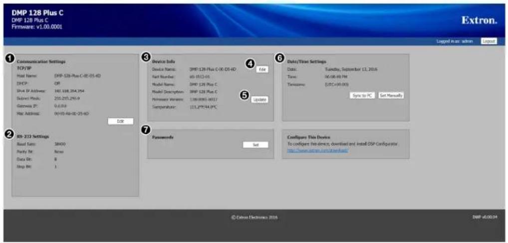
① Communications Settings Panel
⑤ Firmware Update Button
② RS-232 Settings Panel
⑥ Date/Time Settings Panel
③ Device Info Panel
⑦ Passwords Panel
4 Device Name Edit Button
Figure 198. DMP 128 Plus Web Page
Communications Settings Panel — Displays TCP/IP communication settings. Click Edit to open the Communication Settings dialog box and edit the TCP/IP settings.
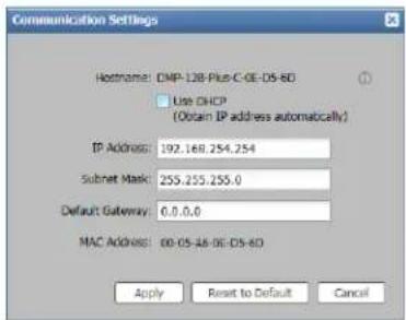
Figure 199. Communication Settings Dialog Box
From this dialog box DHCP status, IP address, subnet mask, and default gateway can be edited. The device MAC address can also be viewed in this dialog box.
NOTE: If Use DHCP is enabled, IP address, subnet mask, and default gateway can not be edited.
② RS-232 Settings Panel — Provides a read-only display of device RS-232 settings.
③ Device Info Panel — Displays general device information.
4 Device Name Edit Button — Click the Edit button to the right of the device name to open the Device Name dialog box. In this dialog box, the current name can be edited to a user-defined name or reset back to the default name.
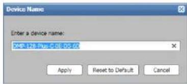
Figure 200. Device Name Dialog Box
5 Firmware Update Button — Click the Update button to open the Firmware Update dialog box.
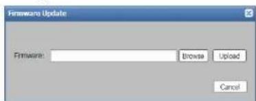
Figure 201. Firmware Update Dialog Box
Click the Browse button to open the Choose a File to Upload dialog box where a firmware file can be selected to upload.
NOTES:
- Only files with a .S19 and .eff extensions are accepted.
- When firmware is version 1.01.0010 or higher, the firmware cannot be downgraded to a version lower than 1.01.0010.
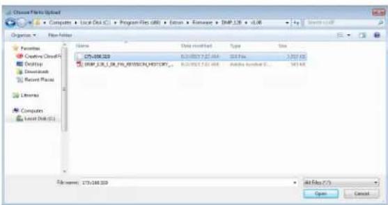
Figure 202. File to Upload Dialog Box
For information regarding the download and installation of firmware files, see Downloading Firmware Updates on page 85.
6 Date/Time Settings Panel — Displays date, time, and time zone information for the device. Click Sync to PC to sync date and time information on the device with the date and time on the host computer. Alternatively, click Set Manually to open the Date and Time Settings dialog box which allows the user to set date, time, and time zone information.
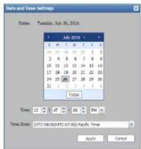
Figure 203. Date and Time Settings Dialog Box
7 Passwords Panel — Click the Set button in the Passwords panel to open the Passwords dialog box which allows users to set admin and user passwords. Enter and confirm a password, then click Apply to apply the password.
NOTE: An administrator password must be applied before a user password can be applied.
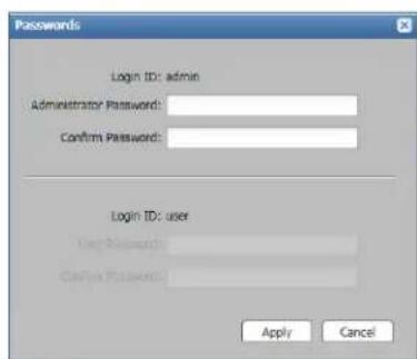
Figure 204. Passwords Dialog Box
DMP 128 Plus VoIP Web Page
Accessing the Embedded VoIP Web Page
- From a web browser, enter the device IP address into the address field followed by /www/voip.html.
NOTE: If the local system administrators have not changed the IP address, and the device has not been assigned an IP address via DHCP, the default address is 192.168.254.254.
-
Press
. -
If a username and password have been set to access the basic DMP 128 Plus web page, the same username and password are required to access the VoIP web page.
Using the VoIP Web Page
Home Page
The Home page displays high level information about the DMP 128 Plus VoIP configuration.
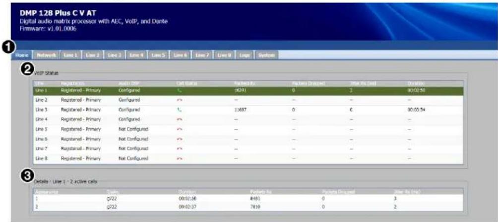
① Navigation Tabs
③ Details Panel
② VoIP Status Panel
Figure 205. VoIP Home Page
① Navigation Tabs — Click these tabs to navigate to the respective pages for network configuration, line registration, system logs, and configuration file import or export.
② VoIP Status Panel — This panel displays the status of the following parameters for each VoIP line:
• Line — Displays the VoIP line number.
- Registration — Displays the current registration status of that line. Registered lines indicate whether the primary or secondary server is used.
- Audio DSP — Displays whether the line is assigned to an Aux channel in the DMP 128 Plus (Configured) or the line is not assigned to an Aux channel (Not Configured) (see Aux Inputs on page 43 for more information).
- Call Status — Displays a green "off hook" (active) or a red "on hook" (inactive) icon depending on the call status of that line.
- Packets Rx — Displays the total number of packets received on the line for the current call.
- Packets Dropped — Displays the total number of packets dropped on that line for the current call.
- Jitter Rx — Displays the current inbound network jitter value for that line in the current call (highest network jitter value if multiple appearances of jitter).
• Duration — Displays the duration of the current call in hh:mm:ss format.
③ Details Panel — Displays the details of each appearance within the line currently selected in the VoIP Status panel including the current codec in use, call duration, packets received, packets dropped, and inbound jitter.
Network Page
The Network page has drop-down ribbons and tabs that are used to configure VoIP network settings. There are four tabs available for VoIP configuration.
- Interface
• Transport on page 171
• QoS/LLDP-MED on the next page
• NAT Traversal on page 173
Interface
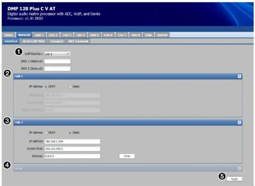
① VoIP Interface
④ VLAN Configuration
② LAN 1 Configuration
⑤ Apply Button
③ LAN 2 Configuration
Figure 206. VoIP Network Interface Page
① VoIP Interface — Select the desired LAN/VoIP port to be used for VoIP network traffic. Options are LAN 1, LAN 2, and VLAN.
NOTE: Only select VLAN when joining a tagged network port on the switch. LAN 1 or LAN 2 must be selected within the VLAN ribbon. Enter an appropriate VLAN ID tag and select DHCP or Static IP configuration.
② LAN 1 Configuration — Select DHCP, or select Static and enter a valid IP configuration.
③ LAN 2 Configuration — Select DHCP, or select Static and enter a valid IP configuration.
4 VLAN Configuration — This ribbon is only available when VLAN is selected from the VoIP Interface drop-down. Use the fields to enter a VLAN IP configuration.
⑤ Apply Button — Click the Apply button to commit interface changes to the device.
QoS/LLDP-MED
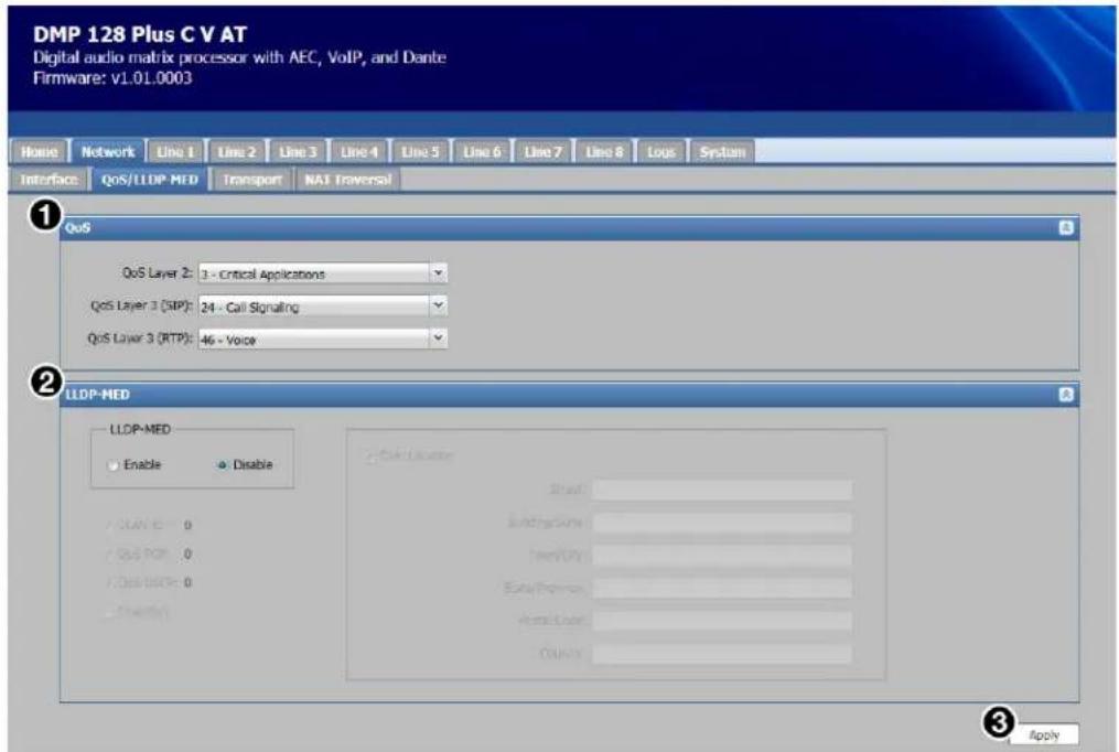
① QoS Configuration
③ Apply Button
② LLDP-MED Configuration
Figure 207. VoIP Network QoS/LLDP-MED Page
① QoS Configuration
- Use the QoS Layer 2 drop-down to specify the PCP (Priority Code Point) decimal value for layer 2 network frames. The default selection is 3 - Critical Applications.
- Use the QoS Layer 3 (SIP) drop-down to specify the DSCP (Differentiated Services Code Point) decimal value for layer 3 SIP network packets. The default selection is 24 - Call Signaling.
- Use the QoS Layer 3 (RTP) drop-down to specify the DSCP (Differentiated Services Code Point) decimal value for layer 3 RTP network packets. The default selection is 46 - Voice.
NOTE: Consult the VoIP system administrator before changing any QoS values.
② LLDP-MED Configuration
- Select Enable or Disable (default) for LLDP-MED (Link Layer Discovery Protocol - Media Endpoint Discovery).
- Select the VLAN ID checkbox to read the voice VLAN ID from the network and automatically configure the DMP 128 Plus VLAN tag (VLAN must be selected as the interface for this feature to work).
-
Select the Qos PCP checkbox to read PCP values from the network and automatically configure layer 2 QoS.
-
Select the QoS DSCP checkbox to read DSCP values from the network and automatically configure layer 3 QoS.
NOTE: VLAN ID, QoS PCP, and QoS DSCP values read from the network and applied to the DMP 128 Plus overwrite any manually specified values.
- Select the Inventory checkbox to send the DMP 128 Plus model number, part number, and firmware details to the network switch.
- Select the Civic Location checkbox to send the location details entered into the Civic Location panel. This is useful when logging the physical location of the DMP 128 Plus for network management purposes.
③ Apply Button — Click the Apply button to commit Qos and LLDP-MED changes to the device.
Transport
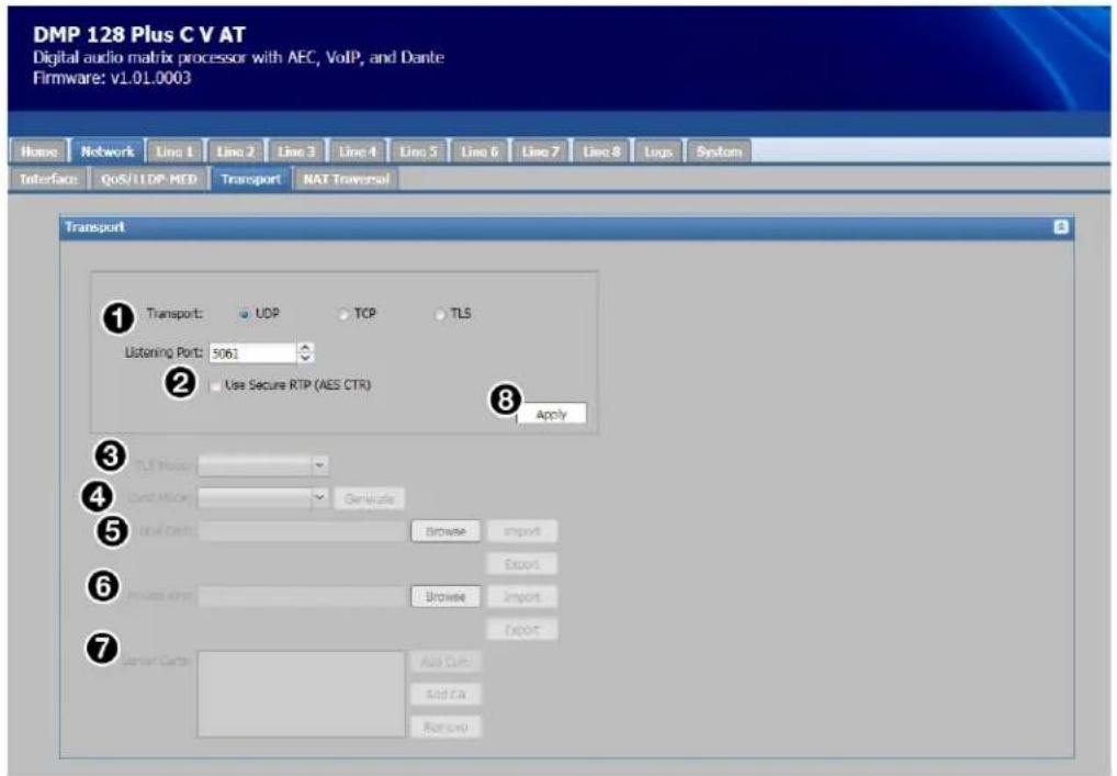
① Transport Protocol Configuration
② Use Secure RTP (AES CTR) Checkbox
③ TLS Mode Drop-Down
④ Local Mode Drop-Down
⑤ Local Cert
⑥ Private Key
⑦ Server Certs
⑧ Apply Button
Figure 208. VoIP Network Transport Page
① Transport Protocol Configuration — Select UDP (default), TCP, or TLS transport protocols.
NOTE: When TLS is selected, the listening port changes from 5060 to 5061. The listening port can be manually adjusted.
② Use Secure RTP (AES CTR) Checkbox — Check this box to encrypt RTP audio streams using the AES CTR cipher.
③ TSL Mode Drop-Down — Choose Always Allow or Always Verify TLS modes.
NOTE: This option is only available when TLS is selected as the transport protocol.
4 Local Mode Drop-Down — Choose a default local certificate or upload a custom local certificate to the DMP 128 Plus. When the default certificate is selected, click Generate to force the DMP 128 Plus to self-generate a new local certificate and private key. Self-generated certificates can be exported by clicking the Export button.
NOTE: Certificates and private keys must be in the Privacy Enhanced Mail (PEM) format. The certificate filename cannot be longer than 32 characters, including the .pem extension.
5 Local Cert — If Local Mode is set to Upload, click the Browse button to locate a certificate on the host PC. Click Import to commit this certificate to the DMP 128 Plus. Click Export to save the current local certificate to the default download directory of the web browser on the host PC.
6 Private Key — If Local Mode is set to Upload, click the Browse button to locate a private key on the host PC. Click Import to commit this key to the DMP 128 Plus. Click Export to save the current private key to the default download directory of the web browser on the host PC.
7 Server Certs — Displays up to eight server certificates that can be stored on the DMP 128 Plus at any one time. The following buttons are also available.
- Add Cert — Click to add a server certificate to the system.
- Add CA — Click to add a Certificate Authority certificate to the system.
- Remove — Highlight a listed certificate and click this button to remove it from the system.
8 Apply Button — Commits changes made to the transport protocol configuration to the DMP 128 Plus.
NAT Traversal
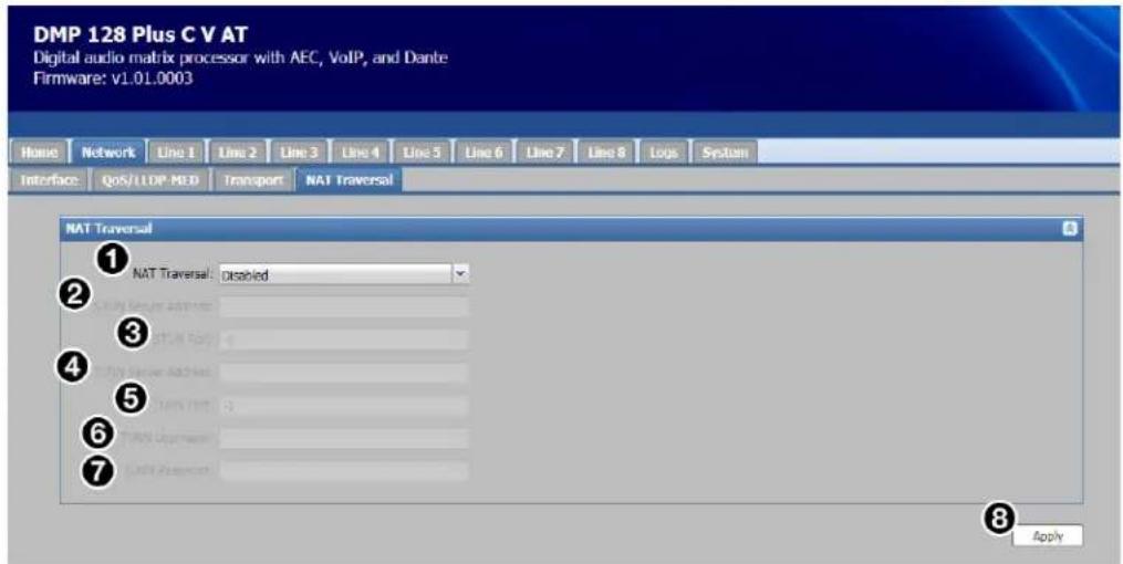
① NAT Traversal Configuration
② STUN Server Address
③ STUN Port
④ TURN Server Address
⑤ TURN Port
⑥ TURN Username
⑦ TURN Password
⑧ Apply Button
Figure 209. VoIP Network NAT Traversal Page
① NAT Traversal Configuration — From the drop-down, select Disabled (default), STUN Server, TURN Server, or STUN/TURN (ICE) as the NAT traversal method used by the system.
NOTE: When NAT Traversal is set to STUN/TURN (ICE), both STUN and TURN fields can be completed. ICE then automatically determines the appropriate method for traversal.
② STUN Server Address — Specify the IP address or domain name of the STUN server to be used.
③ STUN Port — Specify the port number of the STUN server.
4 TURN Server Address — Specify the IP address or domain name of the TURN server to be used.
⑤ TURN Port — Specify the port number of the TURN server.
⑥ TURN Username (optional) — Enter the username for the TURN server, if one is required.
⑦ TURN Password (optional) — Enter the password for the TURN server, if one is required.
⑧ Apply Button — Click Apply to commit changes.
NOTE: When changes are committed with the Apply button, network services on the DMP 128 Plus restart. This process can take up to 30 seconds.
NOTE: For more information regarding VoIP network configuration, refer to the DMP 128 Plus product page on www.extron.com.
Line Pages
Click a Line tab for configuration options. There are three pages used for line configuration.
Registration Page
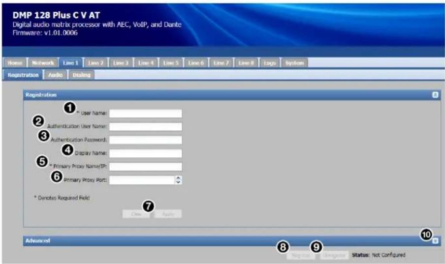
Figure 210. VoIP Line Registration Page
To register a SIP account:
- In the User Name field (see figure 210, ① above), enter the user name currently assigned to the DMP 128 Plus through the call server.
NOTE: "User Name" is referred to as "Line Extension" by some call servers.
- In the Authentication User Name field (②), enter a name for the line (optional). In some cases, this will be the same as the user name entered in step 1.
- In the Authentication Password field (③), enter the call server registration password.
NOTE: If a password is not required by the call server, leave this field blank.
- In the Display Name field (④), enter a display name for the line (optional).
- In the Primary Proxy Name/IP field (⑤), enter the call server IP address or domain name.
- In the Primary Proxy Port field (⑥), enter the SIP traffic port number.
NOTE: If no port number is specified by the user, 5060 is used by default.
- Click Apply (7) to commit the changes to the DMP 128 Plus (click Clear to clear all fields). Committing the changes does not initiate line registration with the call server.
- Click Register (⑧) to initiate registration with the call server. Registration is confirmed in the Status field next to the Register button.
NOTE: If registration is unsuccessful, refer to the logs page (see Logs Page on page 177) and contact the VoIP system administrator.
NOTES:
• To unregister a line from the call server, click Unregister (⑨).
• To clear data from a field, delete the data from the field and click Apply (7).
Advanced Options
The Advanced ribbon (see figure 210, 10 on the previous page) at the bottom of the page allows a secondary proxy to be specified for redundancy purposes.
Audio Page
On the Audio page, codecs can be added or removed from the selected line. Codecs added to the line are available during call negotiation. A minimum of one codec must be present in the Assigned column. Codecs placed higher on the list are treated as preferred codecs during call negotiation.
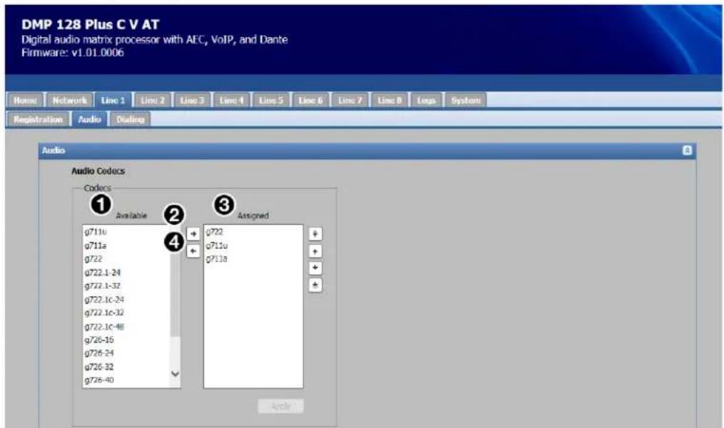
Figure 211. VoIP Line Audio Configuration Page
To add a codec to the Assigned column:
- Select the desired codec in the Available column (see figure 211, ① above).
- Click the right arrow (②) button between the two columns.
- The codec moves from the Available column to the Assigned column (③).
To change codec priority in the Assigned column:
- Select a codec in the Assigned column (①).
- Click and drag that codec to the desired position in the list.
To remove a codec from the Assigned column:
- Select the codec in the Assigned column ( ①).
- Click the left arrow button between the two columns (④).
- The codec moves from the Assigned column to the Available column (③).
Click Apply to commit changes to codec configuration.
Dialing Page
The Dialing page allows dialing behavior to be configured for the selected line.
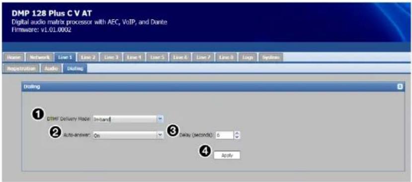
① DTMF Delivery Mode
③ Delay (seconds) Field
② Auto-answer Drop-Down
④ Apply Button
Figure 212. VoIP Line Dialing Page
① DTMF Delivery Mode — Select the DTMF delivery mode.
NOTE: Always consult with the VoIP system administrator to determine the correct DTMF mode.
② Auto-answer Drop-Down — Use this drop-down menu to turn auto-answer features On or Off.
③ Delay (seconds) Field — If auto-answer is enabled, enter the amount of delay in seconds before the call is automatically answered.
④ Apply Button — After configuring the dialing behavior of the selected line, click Apply to commit the changes to the line.
Logs Page
The Logs page provides a running log of SIP transaction relating to all lines on the device. Issues such as registration errors and call failures can be identified on this page without having to use external troubleshooting tools.
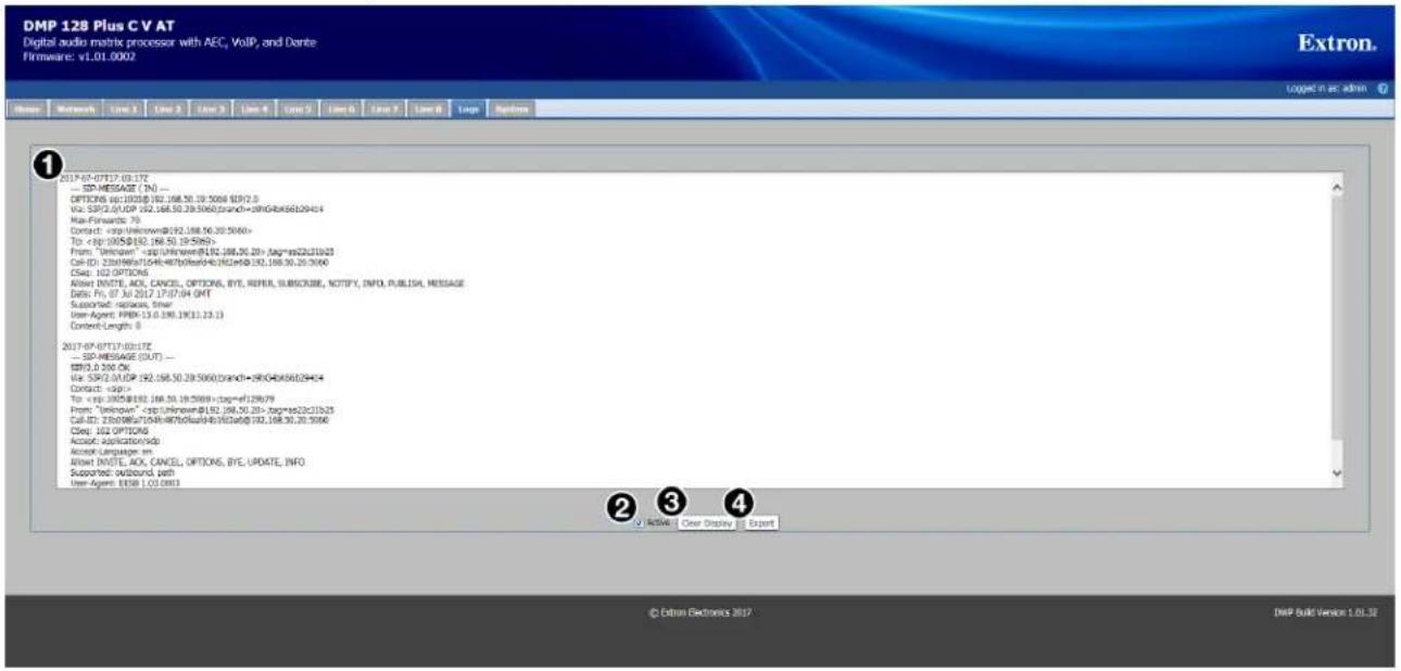
To import a system configuration:
1. Click Browse (①) in the Import System Configuration panel. 2. Locate the system configuration file to be imported. 3. Click Import (②). NOTE: It may take up to 30 seconds to import settings. A dialog box opens to indicate a successful import.To export a system configuration:
1. Click Export (③) in the Export System Configuration panel. 2. The exported JSON file is automatically stored in the default download directory of the web browser.Special Characters
The HTML language reserves certain characters for specific functions. The device does not accept the following characters as part of preset names, device names, passwords, or locally create file names: $$ \{\text { space } \} + -, @ = ^ {\prime} [ ] \{\} < > ^ {\prime \prime};: \backslash |? $$Extron Warranty
Extron Electronics warrants this product against defects in materials and workmanship for a period of three years from the date of purchase. In the event of malfunction during the warranty period attributable directly to faulty workmanship and/or materials, Extron Electronics will, at its option, repair or replace said products or components, to whatever extent it shall deem necessary to restore said product to proper operating condition, provided that it is returned within the warranty period, with proof of purchase and description of malfunction to:USA, Canada, South America, and Central America:
Extron Electronics 1230 South Lewis Street Anaheim, CA 92805 U.S.A.Japan:
Extron Electronics, Japan Kyodo Building, 16 Ichibancho Chiyoda-ku, Tokyo 102-0082 JapanEurope and Africa:
Extron Europe Hanzeboulevard 10 3825 PH Amersfoort The NetherlandsChina:
Extron China 686 Ronghua Road Songjiang District Shanghai 201611 ChinaAsia:
Extron Asia Pte Ltd 135 Joo Seng Road, #04-01 PM Industrial Bldg. Singapore 368363 SingaporeMiddle East:
Extron Middle East Dubai Airport Free Zone F13, PO Box 293666 United Arab Emirates, Dubai This Limited Warranty does not apply if the fault has been caused by misuse, improper handling care, electrical or mechanical abuse, abnormal operating conditions, or if modifications were made to the product that were not authorized by Extron. NOTE: If a product is defective, please call Extron and ask for an Application Engineer to receive an RA (Return Authorization) number. This will begin the repair process. USA: 714.491.1500 or 800.633.9876 Europe: 31.33.453.4040 Asia: 65.6383.4400 Japan: 81.3.3511.7655 Units must be returned insured, with shipping charges prepaid. If not insured, you assume the risk of loss or damage during shipment. Returned units must include the serial number and a description of the problem, as well as the name of the person to contact in case there are any questions. Extron Electronics makes no further warranties either expressed or implied with respect to the product and its quality, performance, merchantability, or fitness for any particular use. In no event will Extron Electronics be liable for direct, indirect, or consequential damages resulting from any defect in this product even if Extron Electronics has been advised of such damage. Please note that laws vary from state to state and country to country, and that some provisions of this warranty may not apply to you.
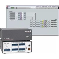
- Mixers and Processors
- DMP 128 Plus
- Safety Instructions
- Safety Instructions • English
- Trademarks
- FCC Class A Notice
- Battery Notice
- Conventions Used in this Guide
- Notifications
- Software Commands
- Specifications Availability
- Extron Glossary of Terms
- Contents
- Introduction......1
- Installation....4
- DSP Configurator Software....10
- Configuration Tools....67
- Audio Control Panels (ACP) 98
- Dante Controller ....107
- Remote Communication and Control.....123
- Web Pages....164
- Introduction
- About this Guide
- About the DMP 128 Plus
- Features
- Installation
- DMP 128 Plus Models
- Mounting
- ATTENTION:
- Front Panel Features
- Figure 10. DMP 128 Plus Front Panel
- Hardware Reset Modes
- Mode 1 — Firmware Reset
- Mode 4 — IP Reset
- Mode 5 — Factory Default Reset
- DSP Configurator Software
- Downloading and Installing DSP Configurator
- Accessing the DSP Configurator Help File
- DSP Configurator Main Workspace
- Menu Bar
- File
- Edit
- View
- Tools
- Window
- Help
- Macros Drop-Down
- Presets Drop-Down
- DSP Configurator Status Panel
- Live and Emulate Panel
- Emulate Mode
- Live Mode
- Connect to a DMP 128 Plus in Live Mode
- Exit Live Mode and Enter Emulate Mode
- DSP Configurator Inputs
- Mic/Line Inputs
- Naming an Input Channel
- Input Building Blocks
- Input Processing
- Input Gain Block
- Input Filter Block
- Input AEC Block (C Models Only)
- About AEC
- AEC Operation
- AEC Advanced Options
- Input Dynamics Blocks
- AGC (Automatic Gain Control)
- Compressor
- Limiter
- Noise Gate
- Figure 60. Noise Gate Dialog Box
- Input Delay Block
- Input Ducking Block
- Ducker
- Adaptive Gain
- Input Automix Block
- Automixer Gate Monitoring
- Input Pre-Mixer Gain Block
- Aux Inputs
- Renaming an Aux Input
- Aux Input Building Blocks
- Aux Input Processing
- Aux Input Gain Block
- Player Input
- USB Input
- VoIP Input
- Aux Input Dialog Box
- Aux Input Filter Block
- Aux Input Dynamics Block
- Aux Input Ducking Block
- Aux Input Automix Block
- Aux Input Pre-Mixer Gain Block
- Virtual Returns
- Renaming a Virtual Return
- Virtual Return Building Blocks
- Virtual Return Processing
- Virtual Return Feedback Suppressor Block
- Feedback Suppressor
- Figure 85. Feedback Suppressor Block and Drop-Down Menu
- Feedback Suppressor Dialog Box
- Virtual Return Filter Block
- Virtual Return Dynamics Block
- Virtual Return Delay Block
- Virtual Return Pre-Mixer Gain Block
- Expansion and AT Inputs
- Renaming an Expansion or AT Input
- NOTES:
- Expansion and AT Inputs Overview
- Expansion and AT Inputs Processing
- Expansion and AT Input Automix Block
- Expansion and AT Input Pre-Mixer Gain Block
- Mix-Points
- Naming an Output
- Output Building Blocks
- Output Processing
- Output Trim Block
- Output Delay Block
- Output Filter Block
- Output Dynamics Block
- Output Attenuation Block
- Aux Outputs
- Naming an Aux Output
- Aux Output Processing
- Aux Output Trim Block
- Aux Output Filter Block
- Aux Output Dynamics Block
- Aux Output Gain Block
- Expansion Outputs
- Naming an Expansion Output
- Expansion Output Processing
- Expansion Output Trim Block
- Expansion Output Delay Block
- Expansion Output Filter Block
- Expansion Output Dynamics Block
- Expansion Output Attenuation Block
- Virtual Send Bus
- Configuration Tools
- Presets
- Methods for Marking Items
- Configuring Presets
- Groups
- Figure 126. Group Controls Dialog Box
- Configuring Groups
- To create a new group:
- To edit an existing group:
- Digital I/O
- Figure 130. Configure Digital I/O Dialog Box
- Configuring Digital I/O
- To push the Digital I/O configuration to a DMP 128 Plus:
- Players
- Configuring Players
- To upload an audio file:
- To assign an audio file to a player:
- To start, stop, or clear a player:
- Macros
- Configuring a Macro
- To delete a Macro:
- To clone a Macro:
- To run a Macro:
- To edit remote destinations:
- Manipulating Macro Actions
- To cut a macro action:
- To copy a macro action:
- To paste a macro action:
- To insert a macro action:
- To delete a macro action:
- Device Manager
- Managing Devices in Device Manager
- To add a device:
- To arrange devices into a folder:
- Connect to or Disconnect from Device
- Firmware Loader
- Downloading Firmware Updates
- Organize Building Blocks
- Device Settings
- Unit Info
- IP Settings
- Passwords
- Serial Settings
- Date/Time
- To set the date and time:
- Dante Device
- Dante Device Name
- To assign the Dante device name:
- Dante Device Network Settings
- To configure Dante network settings:
- To reboot the Dante interface:
- To refresh the device name and network configuration displayed:
- Redundant Mode
- To enable redundant mode:
- Options
- Expansion Bus
- Connecting the EXP Ports
- Connecting a DMP 128 Plus non-AT with Another EXP-Enabled non-AT Device
- Connecting a DMP 128 Plus AT Device and an EXP-enabled non-AT Device
- Phone Dialer
- Figure 165. Phone Dialer Dialog Box
- Placing a Call with the Phone Dialer
- Receiving a Call with the Phone Dialer
- Audio Control Panels (ACP)
- ACP Panel Types
- Panel ID #
- ACP Panel Button Control Types
- Action-Fixed
- Action-Follow Selector
- Selector-Vol/Mute (Selector)
- Button Labels
- Using Multiple ACP Panels
- Configuration Examples
- ACP 100 Configuration Example
- ACP 106 Style Configuration Example
- Saving and Pushing ACP Configurations
- Dante Controller
- Overview
- Downloading and Installing Dante Controller
- To download Dante Controller:
- Configuring the DMP 128 Plus AT in Dante Controller
- Device Name
- Receiver and Transmitter Names
- Dante Controller Naming Conventions
- Renaming the DMP 128 Plus AT in Dante Controller
- Renaming a Receiver or Transmitter
- Renaming a Receiver
- To rename a DMP 128 Plus AT receiver:
- Renaming a Transmitter
- To rename a DMP 128 Plus AT transmitter:
- Finding a Dante Device IP Address
- Physical Dante Network Setup
- Redundant Configuration
- To configure the DMP 128 Plus in redundant mode using Dante Controller:
- To configure the DMP 128 Plus AT in redundant mode using DSP Configurator:
- Dante Controller Operation
- Dante Transmitters and Receivers
- DMP 128 Plus AT Transmitters and Receivers
- Dante Routing Operation
- Routing Devices
- Creating Subscriptions Between Transmitters and Receivers
- Disconnecting Inputs from Outputs
- Dante Troubleshooting
- Simplifying the Network for Troubleshooting
- Troubleshooting the Network Interface
- Restarting Dante Controller
- Remote Communication and Control
- Connection Options
- RS-232 Port
- LAN Port
- T568A T568B
- T568B
- Establishing a Network Connection via LAN
- USB Config Port
- Verbose Modes
- Tagged and Untagged Responses
- Host-to-Device Communications
- DMP 128 Plus-initiated Messages
- Copyright Message
- Password Prompt
- Using the Command and Response Tables
- Symbol Definitions
- Error Responses
- Simple Control Port Commands
- Command and Response Table Sections
- KEY:
- Mutes
- Group Mutes
- Automix Gate Status
- Signal Presence
- DSP SIS Commands
- Special Characters
- Command and Response Table for VoIP SIS Commands
- Object ID (OID) Number Tables
- Mix-point OIDs
- Web Pages
- DMP 128 Plus Web Page
- Accessing the Embedded Web Page
- Using the Web Page
- DMP 128 Plus VoIP Web Page
- Accessing the Embedded VoIP Web Page
- Using the VoIP Web Page
- Home Page
- Figure 205. VoIP Home Page
- Network Page
- Interface
- Figure 206. VoIP Network Interface Page
- QoS/LLDP-MED
- Figure 207. VoIP Network QoS/LLDP-MED Page
- ① QoS Configuration
- ② LLDP-MED Configuration
- Transport
- NAT Traversal
- Line Pages
- Registration Page
- To register a SIP account:
- Advanced Options
- Audio Page
- Dialing Page
- Logs Page
- Figure 213. VoIP Logs Page
- System Page
- To import a system configuration:
- To export a system configuration:
- Extron Warranty
- USA, Canada, South America, and Central America:
- Japan:
- Europe and Africa:
- China:
- Asia:
- Middle East:
Brand : Extron
Model : DMP 128 Plus C AT
Category : Audio processor