
SF 3C LP - Speaker Extron - Free user manual and instructions
Find the device manual for free SF 3C LP Extron in PDF.


| Product Type | Surface-Mount Speaker |
| Brand | Extron |
| Model | SF 3C LP |
| Driver Size | 3 inches (full-range) |
| Power Handling (RMS) | 30 Watts |
| Impedance | 8 Ohms |
| Frequency Response | 80 Hz - 20 kHz |
| Sensitivity (1W/1m) | 88 dB |
| Dimensions (H x W x D) | 4.5 in x 4.5 in x 5.0 in (114 mm x 114 mm x 127 mm) |
| Weight | 1.5 lb (0.7 kg) |
| Material | ABS Plastic |
| Color | Black or White |
| Mounting Type | Surface mount with included bracket |
| Connection Type | Screw terminal block |
| Coverage Angle | 150° conical |
| Indoor/Outdoor | Indoor only |
| Included Accessories | Mounting bracket, screws, manual |
| Maintenance | Wipe with a damp cloth; do not use solvents |
| Safety | For use in dry locations only; do not expose to moisture |
| Repairability | No user-serviceable parts; contact Extron for service |
Frequently Asked Questions - SF 3C LP Extron
User questions about SF 3C LP Extron
0 question about this device. Answer the ones you know or ask your own.
Ask a new question about this device
Download the instructions for your Speaker in PDF format for free! Find your manual SF 3C LP - Extron and take your electronic device back in hand. On this page are published all the documents necessary for the use of your device. SF 3C LP by Extron.
USER MANUAL SF 3C LP Extron
SF 3C LP and SF 3CT LP
SoundField XD 3" Full-Range Ceiling Speakers with 4" Low Profile Composite Back Can
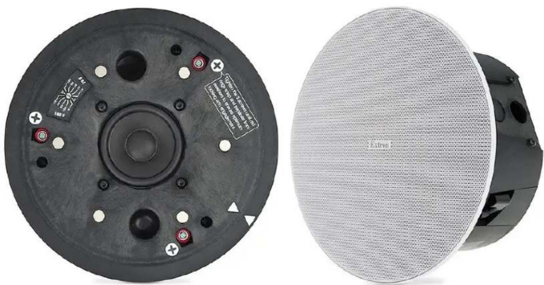
natural_image
Two views of a black circular mechanical component with labeled pins and a separate external mesh fan (no readable text or symbols)Safety Instructions
Safety Instructions • English
|
WARNING: This symbol, , when used on the product, is intended to alert the user of the presence of uninsulated dangerous voltage within the product's enclosure that may present a risk of electric shock.
ATTENTION: This symbol, , when used on the product, is intended to alert the user of important operating and maintenance (servicing) instructions in the literature provided with the equipment.
For information on safety guidelines, regulatory compliances, EMI/EMF compatibility, accessibility, and related topics, see the Extron Safety and Regulatory Compliance Guide, part number 68-290-01, on the Extron website, www.extron.com.
www.extron.com
www.extron.com.
www.extron.com
安全说明·简体中文
All trademarks mentioned in this guide are the properties of their respective owners. The following registered trademarks (®), registered service marks (SM), and trademarks (TM) are the property of RGB Systems, Inc. or Extron (see the current list of trademarks on the Terms of Use page at www.extron.com):
| Registered Trademarks(®) |
| Extron, Cable Cubby, ControlScript, CrossPoint, DTP, eBUS, EDID Manager, EDID Minder, eLink, Flat Field, FlexOS, Glitch Free, Global Configurator, Global Scripter, GlobalViewer, Hideaway, HyperLane, IP Intercom, IP Link, Key Minder, LinkLicense, LockIt, MediaLink, MediaPort, NAV, NetPA, PlenumVault, PoleVault, PowerCage, PURE3, Quantum, ShareLink, Show Me, SoundField, SpeedMount, SpeedSwitch, StudioStation, System INTEGRATOR, TeamWork, TouchLink, V-Lock, VN-Matrix, VoiceLift, WallVault, WindoWall, XPA, XTP, XTP Systems, and ZipClip |
| Registered Service MarkSM: S3 Service Support Solutions |
| Trademarks(TM) |
| AAP, AFL (Accu-RATE Frame Lock), ADSP (Advanced Digital Sync Processing), AVEdge, CableCover, CDRS (Class D Ripple Suppression), Codec Connect, DDSP (Digital Display Sync Processing), DMI (Dynamic Motion Interpolation), Driver Configurator, DSP Configurator, DSVP (Digital Sync Validation Processing), EQIP, Everlast, FastBite, Flex55, FOX, FOXBOX, IP Intercom HelpDesk, MAAP, MicroDigital, Opti-Torque, PendantConnect, ProDSP, QS-FPC (QuickSwitch Front Panel Controller), Room Agent, Scope-Trigger, SIS, Simple Instruction Set, Skew-Free, SpeedNav, Triple-Action Switching, True4K, True8K, VectorTM 4K, WebShare, XTRA, and ZipCaddy |
FCC Class B Notice
NOTE: This device complies with part 15 of the FCC rules. Operation is subject to the following two conditions: (1) This device may not cause harmful interference, and (2) This device must accept any interference received, including interference that may cause undesired operation.
This equipment has been tested and found to comply with the limits for a Class B digital device, pursuant to part 15 of the FCC rules. These limits provide reasonable protection against harmful interference in a residential installation. This equipment generates, uses, and can radiate radio frequency energy and, if not installed and used in accordance with the instructions, may cause harmful interference to radio communications. There is no guarantee that interference will not occur. If this equipment does cause interference to radio or television reception, which can be determined by turning the equipment off and on, you are encouraged to try to correct the interference by one or more of the following measures:
- Reorient or relocate the receiving antenna.
- Increase the separation between the equipment and receiver.
- Connect the equipment into an outlet on a circuit different from that to which the receiver is connected.
- Consult the dealer or an experienced radio/TV technician for help.
In order to maintain compliance with FCC regulations, shielded cables must be used with this equipment. Operation with non-approved equipment or unshielded cables is likely to result in interference to radio and TV reception. The user is cautioned that changes and modifications made to the equipment without the approval of the manufacturer could void the user's authority to operate this equipment.
NOTE: For more information on safety guidelines, regulatory compliances, EMI/EMF compatibility, accessibility, and related topics, see the Extron Safety and Regulatory Compliance Guide on the Extron website.
Conventions Used in this Guide
Notifications
The following notifications are used in this guide:
WARNING: Potential risk of severe injury or death.
NOTE: A note draws attention to important information.
Specifications Availability
Product specifications are available on the Extron website, www.extron.com.
Extron Glossary of Terms
A glossary of terms is available at https://www.extron.com/technology/glossary.aspx.
Contents
Introduction ....1
About this Guide....1
Overview 1
Features 1
Application Diagram 3
Installation....4
Installation Considerations 4
Installation Configurations....4
Installing the Speaker System in a Suspended Ceiling — Single Installer....5
Installing the Speaker System in a Suspended Ceiling — Division of Labor ...... 13
Installing the Speaker System in a Hard Ceiling....24
Painting the Speaker Grille....30
Troubleshooting: Signal Test Points....31 Testing Source Signal (All Configurations)....31
Testing the Impedance (Loop-Through Configuration Only)....32
Introduction
This section gives an overview of the Extron SF 3C LP and SF 3CT LP Full Range 3-inch SoundField Ceiling Speakers with 4-inch Low-Profile Back Can. It also provides a list of system features and an application diagram. Topics include:
- About this Guide
- Overview
- Features
- Application Diagram
About this Guide
This guide describes the SF 3C LP and SF 3CT LP speakers and provides instructions for installing all components of the system in different types of ceilings.
NOTE: Observe all applicable building codes and local ordinances when installing the speaker.
Overview
The SF 3C LP and SF 3CT LP meet stringent UL 2043 requirements for smoke and heat release in plenum air spaces. The 3-inch (76 mm) full-range driver features a frequency range of 65 Hz to 20 kHz and a conical dispersion of 165 degrees. The SF 3C LP and SF 3CT LP feature a thin-edged bezel and a magnetically attached grille.
The SF 3C LP supports 8 ohm operation. The SF 3CT LP supports 70 V, 100 V, and 8 ohm direct operation. The SF 3CT LP has a 6-position rotary switch for selecting the various power taps for 70V, 100V, or 8 ohms. The two models are physically similar, with slight variations in weight and front baffle appearance.
The Extron SoundField SF 3C LP and SF 3CT LP are full-range ceiling speakers with 4-inch (102 mm) low profile composite back cans for use in plenum rated ceiling environments with limited vertical clearance above the ceiling.
Features
• 3-inch (76 mm) full-range driver with a tuned port
• 4-inch (102 mm) deep low profile composite back can for plenum environments
• Frequency range — 65 Hz to 20 kHz
- 165^ conical dispersion
• 16 watts continuous pink noise, 32 watts continuous program
• SF 3C LP — 8 ohm direct
- SF 3CT LP — 8 ohm direct or 70/100 volt operation on a 6 position, behind-the-grille selector
- 8 ohm direct
• 70 volt: 16, 8, 4, 2, and 1 watt selectable
• 100 volt: 16, 8, 4, and 2 watt selectable - Locking arms support ceilings up to 2.25" (57.1 mm) thick.
- Magnetically attached grille with a thin bezel for a refined appearance
- Grille and bezel are white and can be painted to match any environment
- Separable back can and baffle supports both single-trade and division-of-labor applications
- Modular V-rail and folding C-ring kit
- Cable/conduit access plate can be oriented for side or top connections
- Opti-Torque indicator rings prevent overtightening of locking arm screws
- Three locking arms for quick ceiling installation
• UL 2043 plenum rated enclosure
• UL 1480 listed for safety
• Dimensional and weight savings, reduces overall storage and shipping costs
Application Diagram
The illustration below is one example of configuring a system using the SF 3CT LP.
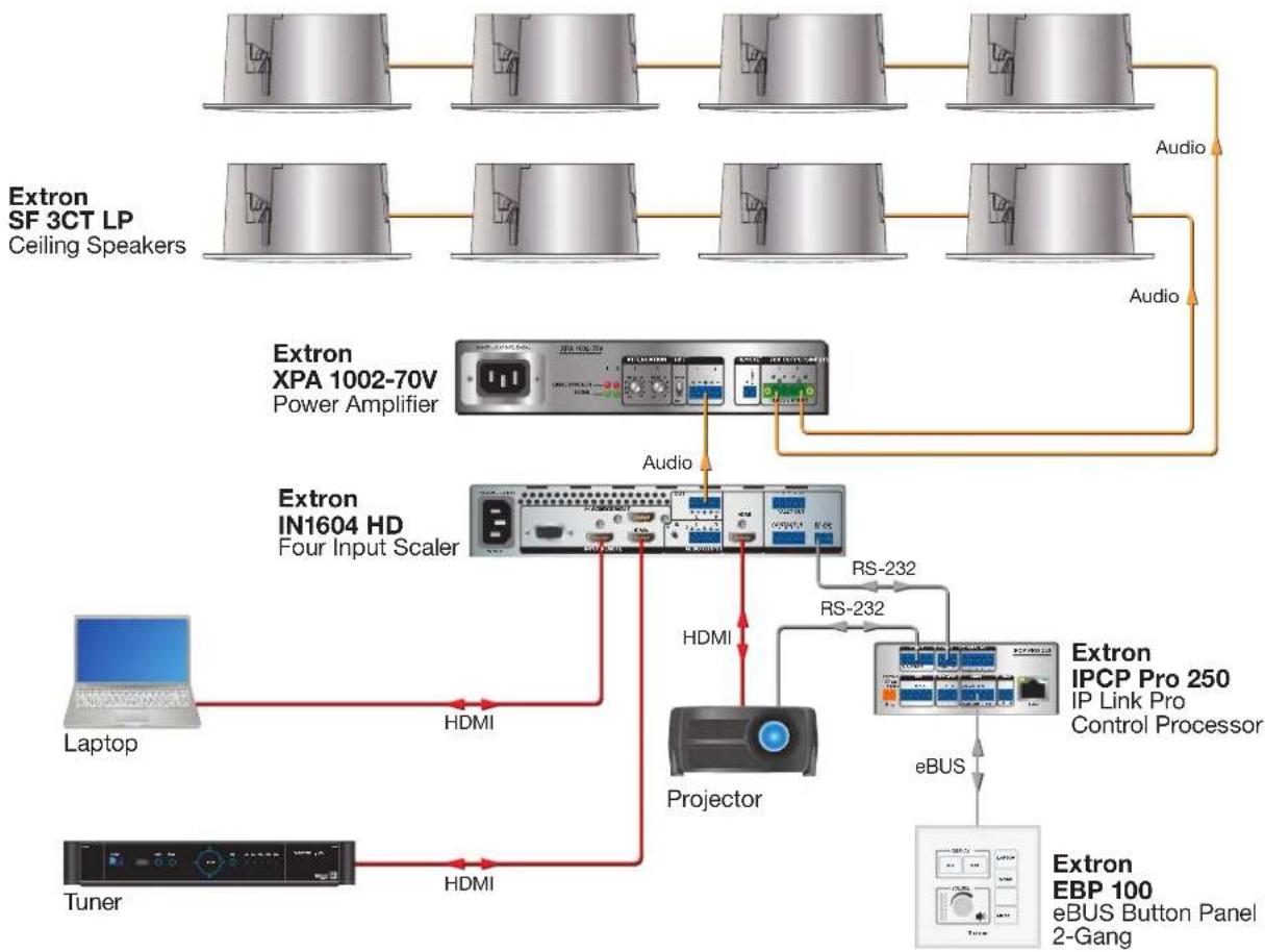
flowchart
graph TD
    A["Extron SF 3CT LP\nCeiling Speakers"] --> B["Extron XPA 1002-70V\nPower Amplifier"]
    B --> C["Extron IN1604 HD\nFour Input Scaler"]
    C --> D["Laptop"]
    C --> E["Tuner"]
    C --> F["Projector"]
    F --> G["Extron IPCP Pro 250\nIP Link Pro\nControl Processor"]
    G --> H["eBUS"]
    H --> I["Extron EBP 100\neBUS Button Panel\n2-Gang"]
    C --> J["HDMI"]
    C --> K["RS-232"]
    C --> L["Audio"]
    C --> M["Audio"]
    C --> N["HDMI"]
    C --> O["RS-232"]
Figure 1. Typical SF 3CT LP Application
Installation
This section provides instructions for installing the SF 3C LP and SF 3CT LP speakers. Topics include:
• Installation Considerations
• Installation Configurations
• Installing the Speaker System in a Suspended Ceiling — Single Installer
• Installing the Speaker System in a Suspended Ceiling — Division of Labor
• Installing the Speaker System in a Hard Ceiling
• Painting the Speaker Grille
- Troubleshooting: Signal Test Points
Installation Considerations
WARNING: Potential risk of severe injury. Installation and service must be performed by authorized personnel only.
- All wiring and electrical connections must conform to all applicable building codes and local ordinances.
• Installation in a plenum-rated environment requires plenum rated cable or conduit. - If using secondary support cables, the installer provides the cables.
Installation Configurations
The SF 3C LP and SF 3CT LP can be configured for the following ceiling types:
- Suspended ceiling: The following sections describe speaker installation procedures for suspended ceilings.
- See Installing the Speaker System in a Suspended Ceiling — Single Installer on page 5.
• See Installing the Speaker System in a Suspended Ceiling — Division of Labor on page 13 - Hard ceiling: For hard ceiling installations, see Installing the Speaker System in a Hard Ceiling on page 24.
Installing the Speaker System in a Suspended Ceiling — Single Installer
If a single installer is installing the speaker system, follow this procedure for the entire system:
-
Disconnect power – Power down all attached devices before proceeding.
-
Verify the space where the system will be installed — Ensure that there is sufficient clearance above the ceiling tile for the unit to be installed.
-
Cut a hole for the speaker — Use the provided cutout template to outline the hole to be cut in the ceiling tile as described below.
a. Remove the ceiling tile.
b. To find the center of the tile, use a tape measure to measure the space between two opposite corners, and mark the half-way point.
c. Position the center hole of the cutout template directly over the center of the tile that you marked in step 3b.
d. Using the provided cutout template, trace a circle around the cutout template.
e. Cut out the circle traced on the ceiling tile.
f. Replace the tile in the ceiling.
- Attach two V-rails and one C-ring across the tile above the hole cut in step 3.
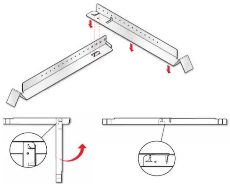
Assemble two V-rail half sections so that they become one single piece:
a. Fit the tab of one end into the slot of the other end.
b. Open the V-rail until it locks together.
c. Repeat this procedure for the other V-rail.
natural_image
Technical illustration of a mechanical assembly with three views showing structural changes (no text or symbols)Figure 2. Assembling the V-rails
d. Remove a ceiling tile adjacent to the tile with the hole.
e. Place both assembled V-rails on the cut ceiling tile and position them equally on either side of the hole. The ends of the V-rails go over the ceiling grid.
f. Position the C-ring assembly on the two V-rails so that the C-ring is centered over the hole, as shown below.
g. Secure the C-ring to the V-rails using two screws.
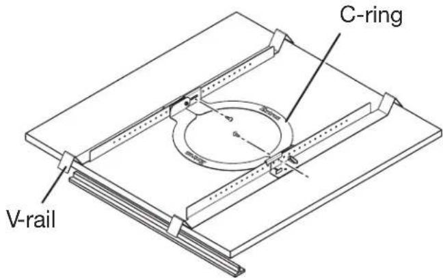
Figure 3. Positioning the C-ring Assembly on the V-rails
-
Route the speaker wires through the ceiling tile hole.
-
Configure the locking arms for thicker ceilings (optional).
Three speaker locking arms are used to secure the speaker to ceiling tiles up to 2.25 inches (57.1 mm) thick. The locking arms are equipped with removable inserts that accommodate ceiling tiles of up to 1.5 inches (38.1 mm) in thickness. For ceiling tiles thicker than 1.5 inches, the locking arm inserts must be removed.
To remove the inserts:
Using a screwdriver, rotate the locking arm so that the insert can be accessed.
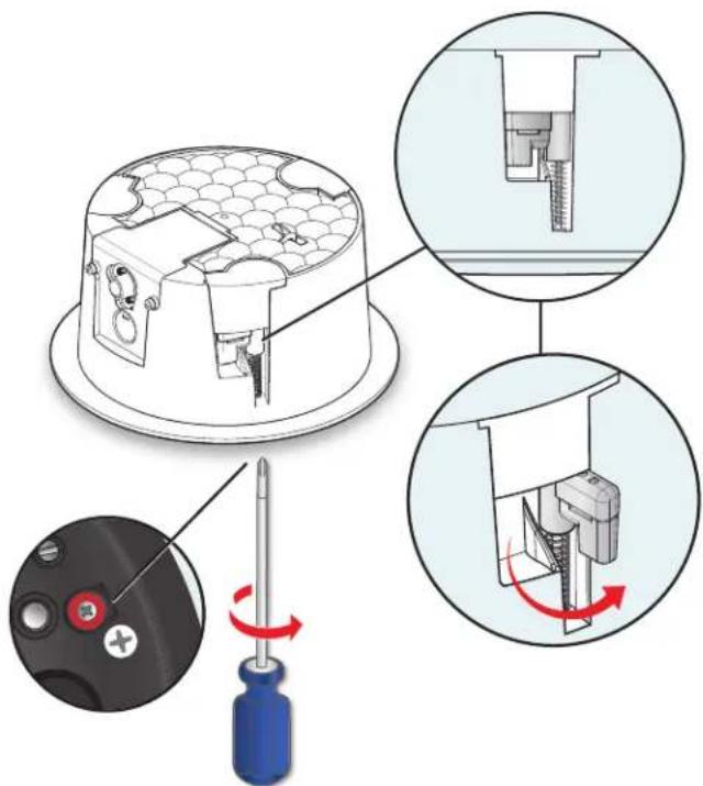
Figure 4. Accessing the Locking Arm Insert
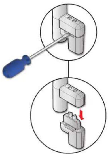
a. Use a small screwdriver to pry and separate the insert from the locking arm.
b. Repeat this process for the remaining two locking arms.
c. Rotate all three locking arms back into the speaker.
7. Configure the cable conduit access plate and captive screw connector.
a. If two conduits are being used, knock out the alternate knockout.
i. Place the head of the screw driver on the notch of the knockout.
ii. Tap the back of the screwdriver until the knockout pops out.
b. Loosen the two side cable conduit access plate screws and remove the plate before wiring the speaker.
natural_image
Diagram showing a screwdriver inserted into a socket, with a close-up view of the socket being inserted (no text or symbols present)Figure 5. Prying off the Locking Arm Insert
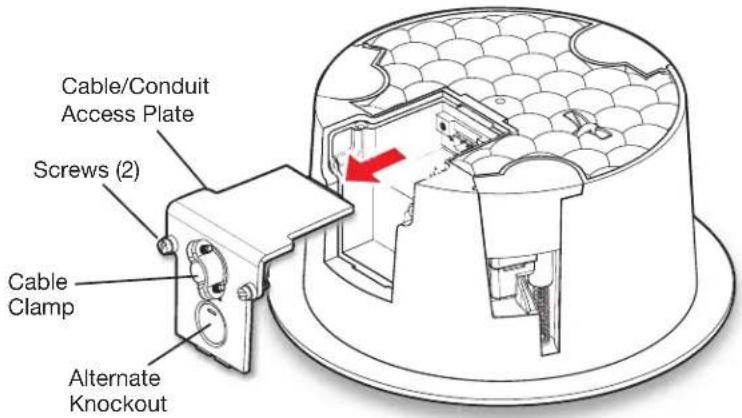
Figure 6. Removing the Cable Conduit Access Plate
c. Configure the cable conduit access plate:
When not using conduit: Route the speaker wires through the cable clamp.
When using conduit: Remove the cable clamp and install the conduit into the plate opening. Secure the conduit to the plate with the locking nut and pull the speaker wires from the conduit.
NOTE: The plate has an alternate hole available by removing the knockout. See step 7a to remove the knockout.
d. Strip 0.2 inches (5 mm) from the wire ends.
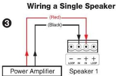
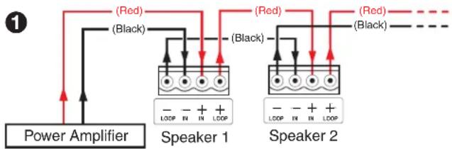
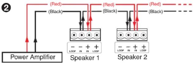
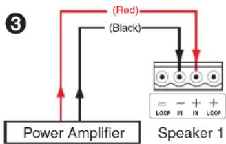
e. Attach the speaker wires to the captive screw connector depending on the configuration, as illustrated by the following three methods.
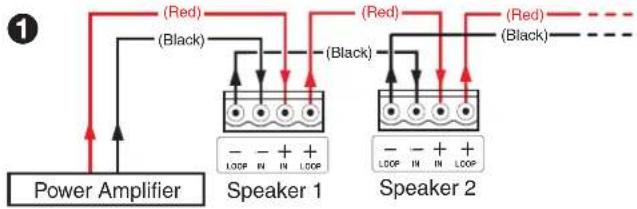
Wiring Multiple Speakers Using Loop-through
When a chain of speakers is wired this way, disconnecting one speaker removes power from all downstream speakers.
flowchart
graph TD
    A["Power Amplifier"] --> B["Speaker 1"]
    B --> C["Speaker 2"]
    C --> D["Red (Red)"]
    C --> E["Black (Black)"]
    B --> F["LOOP IN LOOP"]
    C --> G["LOOP IN LOOP"]
    style A fill:#f9f,stroke:#333
    style B fill:#ccf,stroke:#333
    style C fill:#ccf,stroke:#333
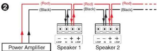
Wiring Multiple Speakers in Parallel
When a chain of speakers is wired this way, disconnecting one speaker does not remove power from the remaining speakers in the chain.
flowchart
graph TD
    A["Power Amplifier"] --> B["(Red)"]
    A --> C["(Black)"]
    B --> D["Speaker 1"]
    C --> D
    D --> E[" terminals: -, +, IN, LOOP"]
    style A fill:#f9f,stroke:#333
    style B fill:#ccf,stroke:#333
    style C fill:#ccf,stroke:#333
    style D fill:#dfd,stroke:#333
| Number of Wires per Connection Point | Maximum Wire Gauge |
| 1 | 12 AWG |
| 2 | 16 AWG |
| 4 | 18 AWG |
Figure 7. Attaching the Speaker Wires to the Connector
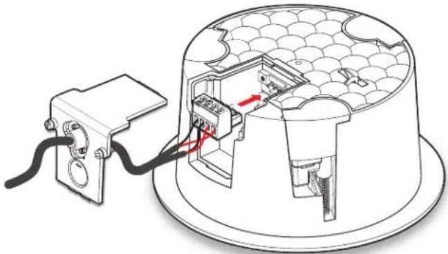
f. Insert the captive screw plug into the four-pole receptacle of the speaker.
Using a cable clamp on the cable conduit access plate:

natural_image
Technical diagram of a device with internal components and wiring, showing no text or symbolsFigure 8. Using a Cable Clamp
Using a conduit adapter on the cable conduit access plate:
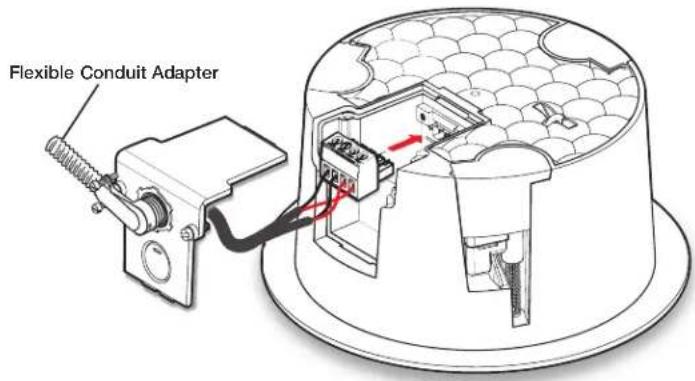
Figure 9. Using a Conduit Adapter
g. Replace the cable conduit access plate and tighten the two retaining screws.
h. Tighten the cable clamp if it was used.
8. Mounting the speaker.
a. Insert the speaker through the bottom of the hole in the ceiling tile that was cut in step 3 on page 5 with the wires out of the way.
b. Clamp the speaker to the C-ring by using a Phillips screwdriver to tighten the three locking arms to the C-ring.
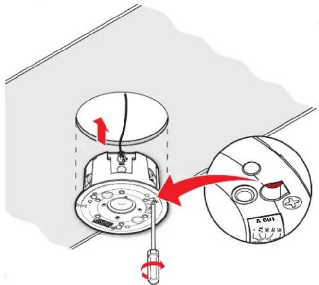
Figure 10. Clamping the Speaker to the C-ring
Tightening the locking arms into rigid material:
Each of the three locking arm screws use an Opti-Torque indicator ring that snaps and separates from its plastic ring when the screw is tightened to the correct torque. The indicator ring falls down the screwdriver shaft. When this occurs, stop tightening the screw to avoid overtightening the locking arms to the C-ring.
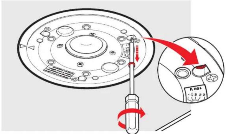
Figure 11. Stop Tightening when the Opti-Torque Indictor Ring Falls
ATTENTION:
Tightening the locking arms into soft material:
Because fiberglass ceilings and other soft materials are not as rigid as mineral tiles and other hard materials, the Opti-Torque indicator rings must not be used as a tightening guide due to the risk of overtightening.
ATTENTION:
natural_image
Two diagrams showing mechanical assembly steps with a black X mark indicating a defect or failure (no text or symbols present)9. If required, attach a secondary support line.
a. Connect a secondary support line to the support loop on the back of the speaker enclosure, as shown here.
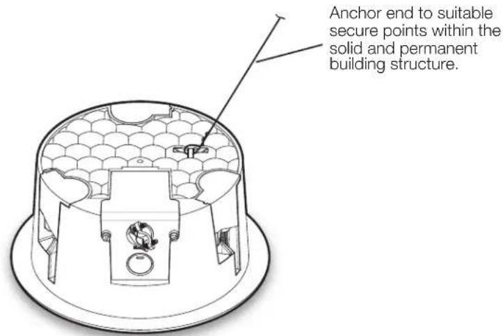
Figure 12. Connecting a Secondary Support Line
ATTENTION:
b. Replace the adjacent ceiling tile that was removed in step 4d on page 5.
- For the SF 3CT LP only, set the rotary tap selector switch to the appropriate setting using a small screwdriver.
ATTENTION:
Figure 13. Setting the Rotary Tap Selector Switch
- Install the grille. Position the grille so that it covers the baffle of the speaker. Six small magnets secure the grille in place.
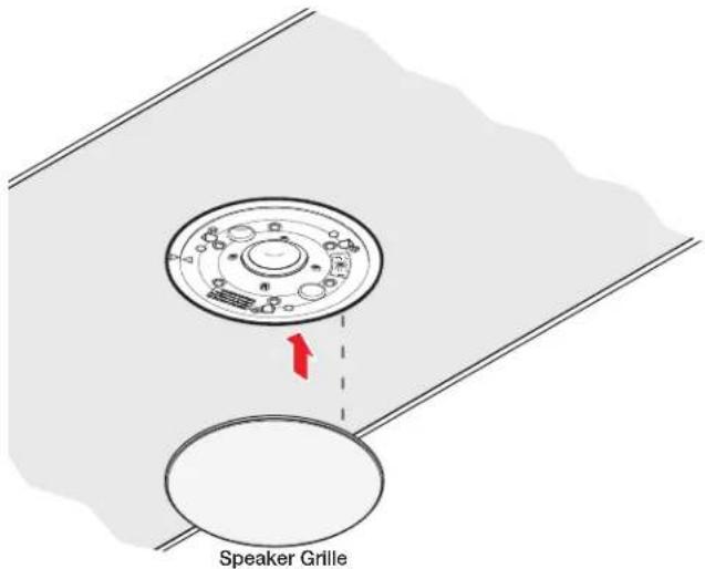
Figure 14. Installing the Grille
NOTE: Specific test points can be used to troubleshoot speaker system problems. Should problems be encountered, please see Troubleshooting: Signal Test Points on page 31.
Installing the Speaker System in a Suspended Ceiling — Division of Labor
In a division of labor installation, low-voltage contractors first install the speaker back can enclosure (construction rough-in phase). After the back can has been installed, the second phase of the installation process can begin by installing the speaker assembly to the back can.
Use the following procedure:
- Using a flat head screwdriver — Completely loosen the three screws holding the speaker assembly to the back can enclosure from the speaker, as shown below.
NOTE: The screws are not removable. They loosen completely, but do not pull out.
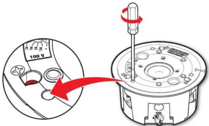
Figure 15. Unscrewing the Speaker Assembly from the Back Can
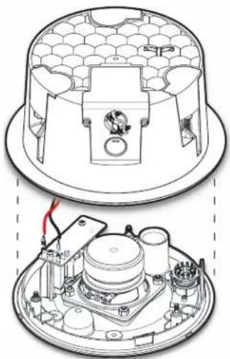
- Separate the speaker assembly from the back can — Carefully separate the speaker assembly from the back can, as shown below.
NOTE: Disconnect the speaker wires from the speaker assembly before completely separating the speaker assembly from the back can.
-
Repeat steps 1 and 2 for each speaker in the system and distribute the components to the appropriate installers.
-
Disconnect power — Power down all attached devices before proceeding.
-
Verify the space where the system will be installed — Ensure that there is sufficient clearance above the ceiling tile for the unit to be installed.
natural_image
Technical line drawing of a device housing with internal components and wiring (no text or symbols)Figure 16. Separating the Speaker Assembly from the Back Can
- Cut a hole for the speaker — Use the provided cutout template to outline the hole to be cut in the ceiling tile as described below.
a. Remove the ceiling tile.
b. To find the center of the tile, use a tape measure to measure the space between two opposite corners, and mark the half-way point.
c. Position the center hole of the cutout template directly over the center of the tile that you marked in step6b.
d. Using the provided cutout template, trace a circle around the cutout template.
e. Cut out the circle traced on the ceiling tile.
f. Replace the tile in the ceiling.
- Attach two V-rails and one C-ring across the tile above the hole cut in step 6, as described below.
Assemble two V-rail half sections so that they become one single piece:
a. Fit the tab of one end into the slot of the other end.
b. Open the V-rail until it locks together.
c. Repeat this procedure for the other V-rail.
Figure 17. Assembling the V-rails
d. Remove a ceiling tile adjacent to the tile with the hole.
e. Place both assembled V-rails on the cut ceiling tile and position them equally on either side of the hole. The ends of the V-rails go over the ceiling grid.
f. Place the C-ring assembly and position it on the two V-rails so that the C-ring is centered over the hole.
g. Secure the C-ring to the V-rails using two screws.
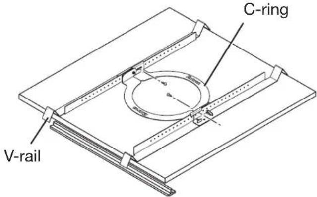
Figure 18. Positioning the C-ring Assembly on the V-rails
-
Route the speaker wires through the ceiling tile hole.
-
Configure the locking arms for thicker ceilings (optional).
Three speaker locking arms are used to secure the speaker to ceiling tiles up to 2.25 inches (57.1 mm) thick. The locking arms are equipped with removable inserts that accommodate ceiling tiles of up to 1.5 inches (38.1 mm) in thickness. For ceiling tiles thicker than 1.5 inches, the locking arm inserts must be removed.
To remove the inserts:
a. Using a screwdriver, rotate the locking arm so that the insert can be accessed.
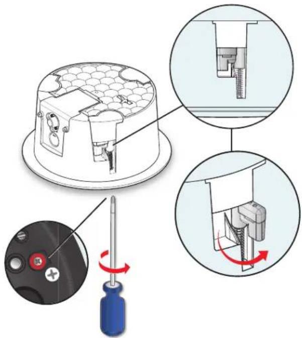
Figure 19. Accessing the locking arm insert
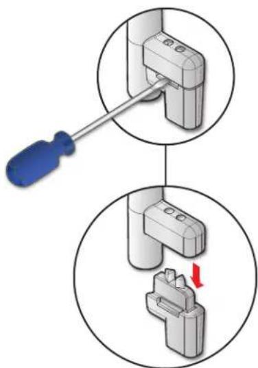
b. Use a small screwdriver to pry and separate the insert from the locking arm.
c. Repeat this process for the remaining two locking arms.
d. Rotate all three locking arms back into the speaker.
10. Configure the cable conduit access plate and captive screw connector of the back can enclosure.
a. If two conduits are being used, knock out the alternate knockout.
i. Place the head of the screw driver on the notch of the knockout.
ii. Tap the back of the screwdriver until the knockout pops out.
b. Loosen the two side cable conduit access plate screws and remove the plate before wiring the back can.
natural_image
Diagram showing a screwdriver inserted into a mechanical component, with a red arrow indicating a specific part (no text or symbols present)Figure 20. Prying off the Locking Arm Insert
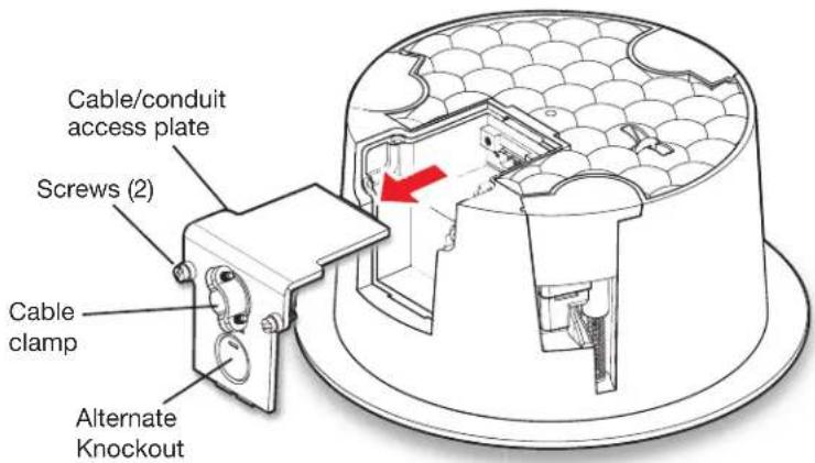
Figure 21. Removing the Cable Conduit Access Plate
c. Configure the cable conduit access plate:
When not using conduit: Route the speaker wires through the cable clamp.
When using conduit: Remove the cable clamp and install the conduit into the plate opening. Secure the conduit to the plate with the locking nut and pull the speaker wires from the conduit.
NOTE: The plate has an alternate hole available by removing the knockout. See step 10a to remove the knockout.
d. Strip 0.2 inches (5 mm) from the wire ends.
e. Attach the speaker wires to the captive screw connector depending on the configuration, as illustrated by the following three methods
Wiring Multiple Speakers Using Loop-through
When a chain of speakers is wired this way, disconnecting one speaker removes power from all downstream speakers.
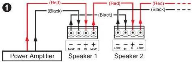
flowchart
graph TD
    A["Power Amplifier"] --> B["Speaker 1"]
    B --> C["Speaker 2"]
    C --> D["Red (Red)"]
    C --> E["Black (Black)"]
    B --> F["Loop IN + IN + Loop"]
    C --> G["Loop IN + IN + Loop"]
    style A fill:#f9f,stroke:#333
    style B fill:#ccf,stroke:#333
    style C fill:#ccf,stroke:#333
Wiring Multiple Speakers in Parallel
When a chain of speakers is wired this way, disconnecting one speaker does not remove power from the remaining speakers in the chain.
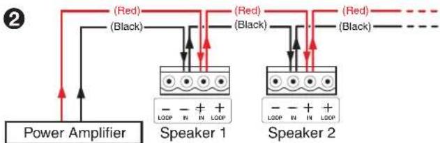
flowchart
graph TD
    A["Power Amplifier"] --> B["Speaker 1"]
    A --> C["Speaker 2"]
    B --> D["Red (Red)"]
    B --> E["(Black) (Black)"]
    C --> F["Red (Red)"]
    C --> G["(Black) (Black)"]
    D --> H["Ground"]
    E --> I["Ground"]
    F --> J["Ground"]
    G --> K["Ground"]
Wiring a Single Speaker
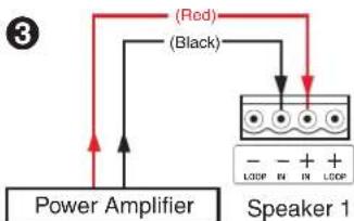
flowchart
graph TD
    A["Power Amplifier"] --> B["Speaker 1"]
    B --> C["Red Signal"]
    B --> D["Black Signal"]
    C --> E["Sound"]
    D --> E
    E --> F["Black Signal"]
    style A fill:#f9f,stroke:#333
    style B fill:#ccf,stroke:#333
    style C fill:#cff,stroke:#333
    style D fill:#ffc,stroke:#333
    style E fill:#cfc,stroke:#333
    style F fill:#fcc,stroke:#333
Wire Gauge Table
| Number of Wires per Connection Point | Maximum Wire Gauge |
| 1 | 12 AWG |
| 2 | 16 AWG |
| 4 | 18 AWG |
Figure 22. Attaching the Speaker Wires to the Connector
ATTENTION:
natural_image
Technical diagram of an electrical connector assembly with a cable and pin, showing internal components (no text or labels)Figure 23. Using a Cable Clamp
Using a conduit adapter on the cable conduit access plate:
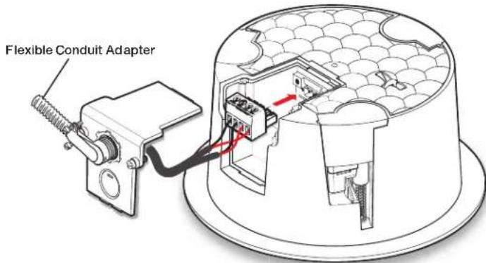
Figure 24. Using a Conduit Adapter
- Replace the cable conduit access plate and tighten the two retaining screws.
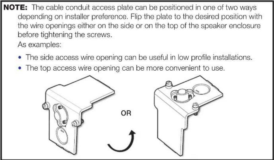
NOTE: The cable conduit access plate can be positioned in one of two ways depending on installer preference. Flip the plate to the desired position with the wire openings either on the side or on the top of the back can before tightening the screws.
As examples:
- The side access wire opening can be useful in low profile installations.
- The top access wire opening can be more convenient to use.
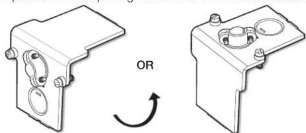
natural_image
Technical line drawing of two mechanical components with mounting holes and a rotation arrow (no text or symbols)- Tighten the cable clamp if it was used.
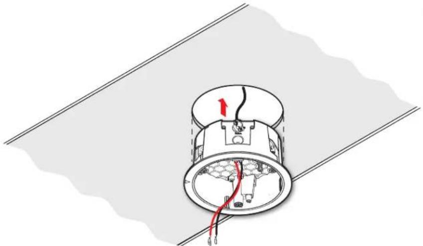
14. Mount the speaker back can enclosure.
a. Insert the back can through the bottom of the hole in the ceiling tile that was cut in step 6 on page 14 with the wires out of the way.
natural_image
Diagram of a mechanical component with internal wiring and a red arrow indicating direction (no text or symbols)Figure 25. Inserting the Speaker Back Can
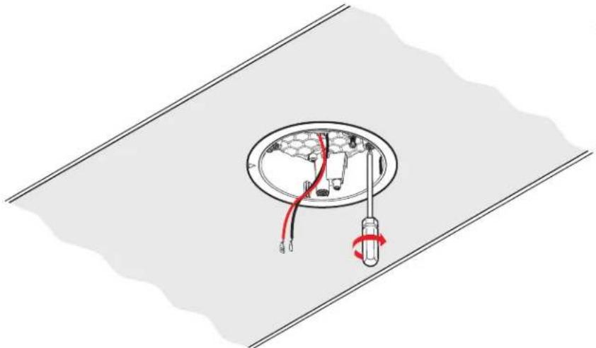
b. Clamp the back can to the C-ring by using a Phillips screwdriver to tighten the three locking arms to the C-ring.
natural_image
Diagram of a ceiling-mounted device with red and black wires, no text or symbols presentFigure 26. Tightening the Locking Arms
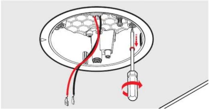
Each of the three locking arm screws use an Opti-Torque indicator ring that snaps and separates from its plastic ring when the screw is tightened to the correct torque. The indicator ring falls down the screwdriver shaft. When this occurs, stop tightening the screw to avoid overtightening the locking arms to the C-ring.
natural_image
Diagram of a screwdriver inserted into a hexagonal component, showing wiring and connection (no text or symbols)Figure 27. The Opti-Torque Indicator Ring Falls
ATTENTION:
Tightening the locking arms into soft material:
Because fiberglass ceilings and other soft materials are not as rigid as mineral tiles and other hard materials, the Opti-Torque indicator rings must not be used as a tightening guide due to the risk of overtightening.
ATTENTION:
natural_image
Pure mechanical diagram showing two vertical supports connected to a horizontal beam, with no text or symbols present.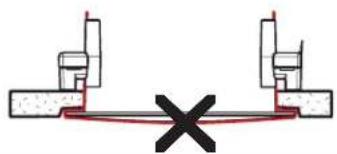
natural_image
Pure mechanical cross-section diagram without any text, numbers, or symbols15. If required, attach a secondary support line.
a. Connect a secondary support line to the support loop on the back of the back can, as shown here.
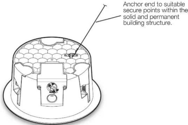
Figure 28. Connecting a Secondary Support Line
ATTENTION:
b. Replace the adjacent ceiling tile that was removed in step 7 on page 14.
- Repeat steps 4 through 15 for each speaker being installed.
- Attach the speaker assembly to the back can enclosure.
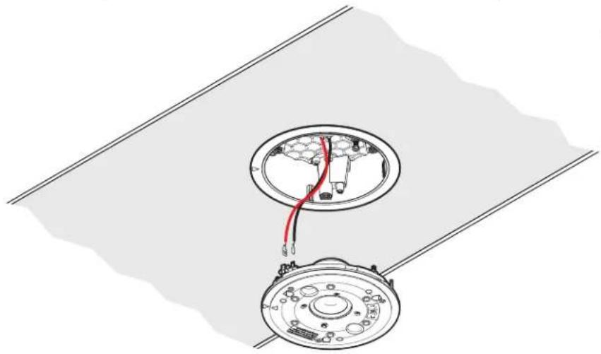
a. Connect the speaker wires from the back can enclosure to the speaker assembly.
natural_image
Technical diagram of a mechanical assembly with two circular components and wiring, no visible text or symbolsFigure 29. Connecting Speaker Wires to the Speaker Assembly
b. Rotate the speaker assembly so that the white arrows on the back can enclosure and the speaker assembly are aligned with each other and insert the speaker into the back can.
c. Using a flat head screwdriver, tighten the three screws that attach the speaker assembly to the back can.
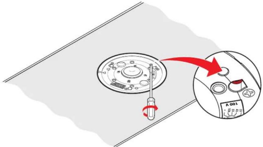
Figure 30. Screwing the Speaker Assembly to the Back Can
ATTENTION:
- For the SF 3CT LP, set the rotary tap selector switch to the appropriate setting using a small screwdriver (see figure 31 on page 23).
ATTENTION:
Figure 31. Setting the Rotary Tap Selector Switch
- Install the grille. Position the grille so that it covers the baffle of the speaker. Six small magnets secure the grille in place.
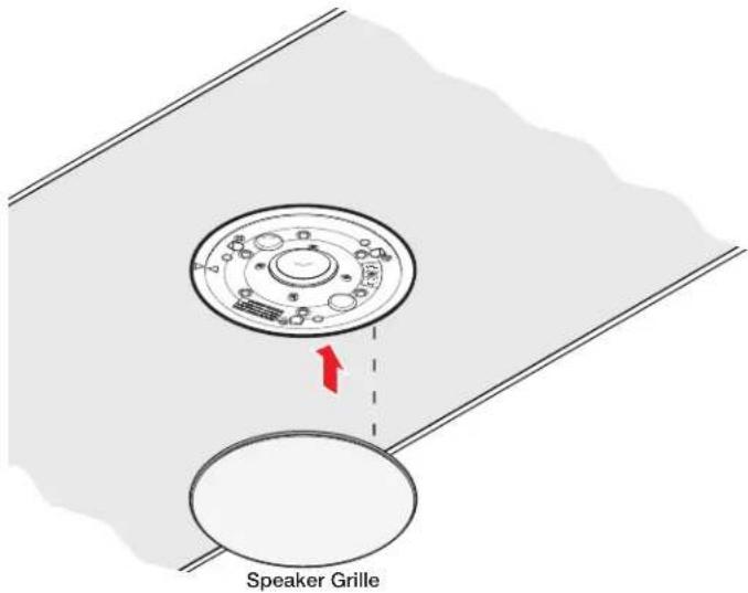
Figure 32. Installing the Grille
NOTE: Specific test points can be used to troubleshoot speaker system problems. Should problems be encountered, please see Troubleshooting: Signal Test Points on page 31.
Installing the Speaker System in a Hard Ceiling
If you are installing the SF 3C LP or SF 3CT LP in a hard ceiling (having no ceiling tiles), with the ceiling structure in place, follow the steps below:
- Disconnect power — Power down all attached devices before proceeding.
- Cut a hole for the speaker — Use the provided cutout template to outline the hole to be cut in the ceiling as described below.
a. Mark the location on the ceiling where the center of the speaker will be placed.
b. Position the center hole of the cutout template directly over the center mark.
c. Trace a circle around the cutout template.
d. Cut out the traced circle.
-
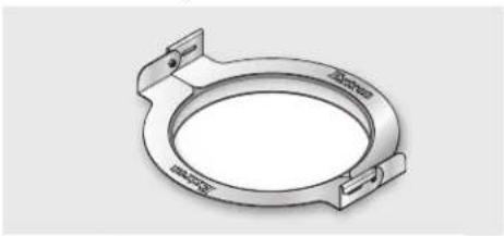
Fold one C-ring assembly in half and insert it through the hole in the ceiling.
-
Unfold the C-ring and center it over the hole with the flat side down.
natural_image
Technical drawing of a circular mechanical component with flanges and mounting brackets (no text or symbols)Figure 33. Installing the C-ring
- Route the speaker wires through the ceiling hole.
- Configure the locking arms for thicker ceilings (optional).
Three speaker locking arms are used to secure the speaker to ceiling tiles up to 2.25 inches (57.1 mm) thick. The locking arms are equipped with removable inserts that accommodate ceiling tiles of up to 1.5 inches (38.1 mm) in thickness. For ceiling tiles thicker than 1.5 inches, the locking arm inserts must be removed.
To remove the inserts:
Using a screwdriver, rotate the locking arm so that the insert can be accessed.
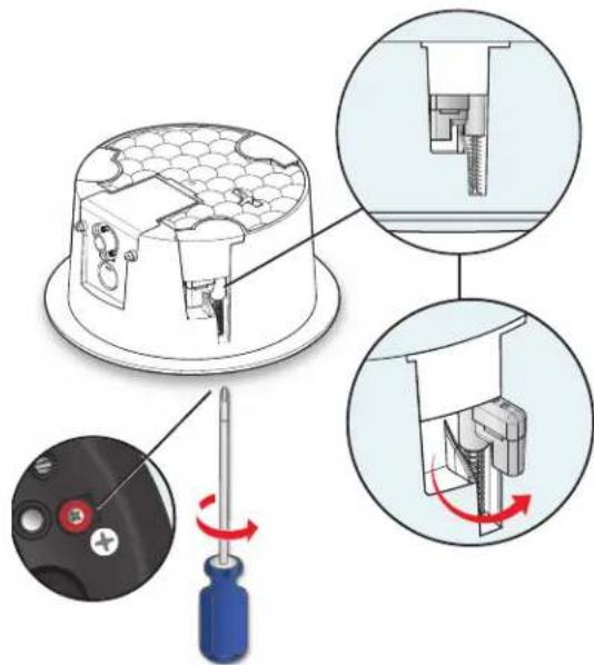
Figure 34. Accessing the locking arm insert
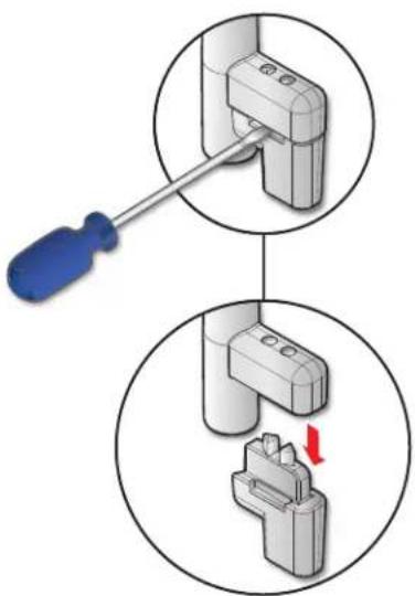
a. Use a small screwdriver to pry and separate the insert from the locking arm.
b. Repeat this process for the remaining two locking arms.
c. Rotate all three locking arms back into the speaker.
7. Configure the cable conduit access plate and captive screw connector.
a. If two conduits are being used, knock out the alternate knockout.
i. Place the head of the screw driver on the notch of the knockout.
ii. Tap the back of the screwdriver until the knockout pops out.
b. Loosen the two side cable conduit access plate screws and remove the plate before wiring the speaker.
natural_image
Diagram showing a screwdriver inserted into a socket, with a close-up view of the socket being inserted (no text or symbols present)Figure 35. Prying off the locking arm insert
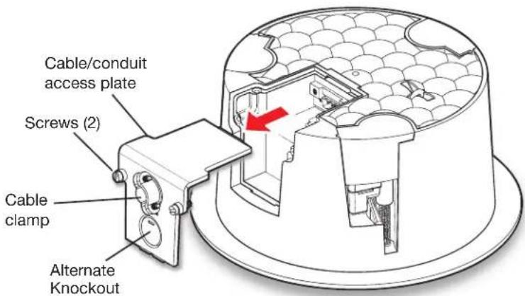
Figure 36. Removing the Cable Conduit Access Plate
c. Configure the cable conduit access plate:
When not using conduit: Route the speaker wires through the cable clamp.
When using conduit: Remove the cable clamp and install the conduit into the plate opening. Secure the conduit to the plate with the locking nut and pull the speaker wires from the conduit.
NOTE: The plate has an alternate hole available by removing the knockout. See step 7a to remove the knockout.
d. Strip 0.2 inches (5 mm) from the wire ends.
e. Attach the speaker wires to the captive screw connector depending on the configuration, as illustrated by the following three methods.
Wiring Multiple Speakers Using Loop-through
When a chain of speakers is wired this way, disconnecting one speaker removes power from all downstream speakers.
flowchart
graph TD
    A["Power Amplifier"] --> B["Speaker 1"]
    B --> C["Speaker 2"]
    C --> D["Black Channel"]
    C --> E["Red Channel"]
    style A fill:#f9f,stroke:#333
    style B fill:#ccf,stroke:#333
    style C fill:#cfc,stroke:#333
    style D fill:#fcc,stroke:#333
    style E fill:#cff,stroke:#333
Wiring Multiple Speakers in Parallel
When a chain of speakers is wired this way, disconnecting one speaker does not remove power from the remaining speakers in the chain.
flowchart
graph TD
    A["Power Amplifier"] --> B["Speaker 1"]
    A --> C["Speaker 2"]
    B --> D["Red (Red)"]
    B --> E["Black (Black)"]
    C --> F["Red (Red)"]
    C --> G["Black (Black)"]
    D --> H["LED"]
    E --> I["LED"]
    F --> J["LED"]
    G --> K["LED"]
Wiring a Single Speaker
flowchart
graph TD
    A["Power Amplifier"] --> B["Speaker 1"]
    B --> C["Red (Red)"]
    B --> D["Black (Black)"]
    C --> E["Loop: - + +"]
    D --> F["Loop: IN IN LOOP"]
Wire Gauge Table
| Number of Wires per Connection Point | Maximum Wire Gauge |
| 1 | 12 AWG |
| 2 | 16 AWG |
| 4 | 18 AWG |
Figure 37. Attaching the Speaker Wires to the Connector
ATTENTION:
f. Insert the captive screw plug into the four-pole receptacle of the speaker.
Using a cable clamp on the cable conduit access plate:
natural_image
Technical diagram of an electrical enclosure with internal components and wiring, showing no text or symbols.Figure 38. Using a Cable Clamp
Using a conduit adapter on the cable conduit access plate:
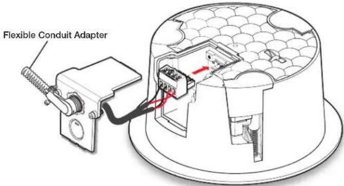
Figure 39. Using a Conduit Adapter
g. Replace the cable conduit access plate and tighten the two retaining screws.
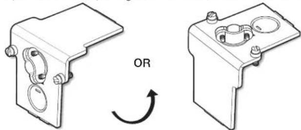
NOTE: The cable conduit access plate can be positioned in one of two ways depending on installer preference. Flip the plate to the desired position with the wire openings either on the side or on the top of the speaker enclosure before tightening the screws.
As examples:
- The side access wire opening can be useful in low profile installations.
- The top access wire opening can be more convenient to use.
natural_image
Technical illustration of two mechanical components with a rotation arrow indicating rotational motion (no text or symbols)h. Tighten the cable clamp if it was used.
- If required, attach a secondary support line. Connect a secondary support line to the support loop on the back of the speaker enclosure, as shown here.
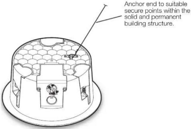
Figure 40. Connecting a Secondary Support Line
ATTENTION:
a. Insert the speaker through the bottom of the hole in the ceiling that was cut in step 2 on page 24 with the wires out of the way.
b. Clamp the speaker to the C-ring by using a Phillips screwdriver to tighten the three locking arms to the C-ring.
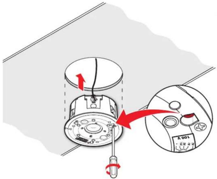
Figure 41. Clamping the Speaker to the C-ring
Each of the three locking arm screws use an Opti-Torque indicator ring that snaps and separates from its plastic ring when the screw is tightened to the correct torque. The indicator ring falls down the screwdriver shaft. When this occurs, stop tightening the screw to avoid overtightening the locking arms to the C-ring.
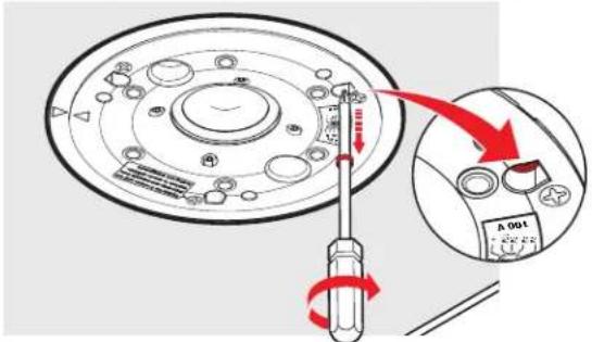
Figure 42. Stop Tightening when the Opti-Torque Indicator Ring Falls
ATTENTION:
- For the SF 3CT LP, set the rotary tap selector switch to the appropriate setting using a small screwdriver.
ATTENTION:
Figure 43. Setting the Rotary Tap Selector Switch
- Installing the grille. Position the grille so that it covers the baffle of the speaker. Six small magnets secure the grille in place.
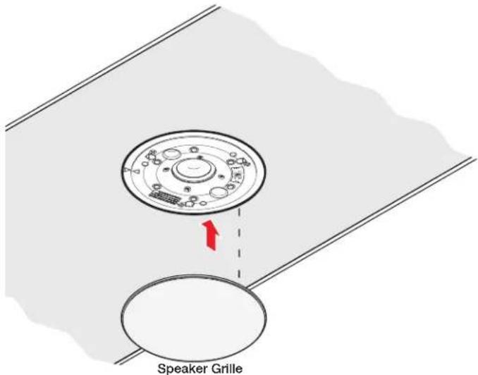
Figure 44. Installing the Grille
NOTE: Specific test points can be used to troubleshoot speaker system problems. Should problems be encountered, please see Troubleshooting: Signal Test Points on page 31.
Painting the Speaker Grille
The speaker grille can be painted using spray paint. Ensure that the spray paint adheres to both metal and plastic.
NOTE: Extron is not responsible for any alterations to the original paint.
To paint the grille:
- Remove the grille from the speaker.
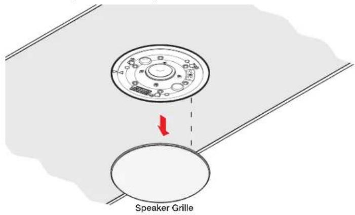
Figure 45. Removing the speaker grille
-
Remove and set aside the scrim from the back side of the grille.
-
Spray paint the front side of the grille.
NOTES:
- Do not paint the back side of the grille.
- Apply an even coat across the entire front surface.
-
Be sure not to clog the grille holes.
-
Wait for the paint to dry.
- Reattach the scrim to the back of the grille.
- Reattach the grille to the speaker.
Troubleshooting: Signal Test Points
Specific test points can be used to troubleshoot speaker system problems.
Testing Source Signal (All Configurations)
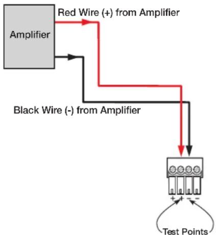
The source signal can be tested by connecting to the inner + (IN) and - (IN) terminals of the captive screw connector.
flowchart
graph TD
    A["Amplifier"] -->|Red Wire (+) from Amplifier| B["Test Points"]
    A -->|Black Wire (-) from Amplifier| B
    B --> C["+"]
    B --> D["-"]
Figure 46. Signal Test Points — Parallel Configuration
Testing the Impedance (Loop-Through Configuration Only)
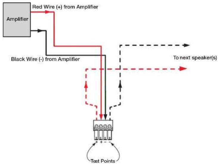
The impedance of the speakers downstream of the one being tested can be measured while the system is on by connecting to the outer (LOOP) terminals of the captive screw connector, as shown below.
flowchart
graph TD
    A["Amplifier"] -->|Red Wire (+) from Amplifier| B["To next speaker(s)"]
    A -->|Black Wire (-) from Amplifier| C["Test Points"]
    C --> D["Output"]
Figure 47. Impedance Test Points — Loop-through Configuration
Extron Warranty
Extron warrants this product against defects in materials and workmanship for a period of three years from the date of purchase. In the event of malfunction during the warranty period attributable directly to faulty workmanship and/or materials, Extron will, at its option, repair or replace said products or components, to whatever extent it shall deem necessary to restore said product to proper operating condition, provided that it is returned within the warranty period, with proof of purchase and description of malfunction to:
USA, Canada, South America, and Central America:
Extron
1230 South Lewis Street
Anaheim, CA 92805
U.S.A.
Asia:
Extron Asia Pte Ltd
135 Joo Seng Road, #04-01
PM Industrial Bldg.
Singapore 368363
Singapore
Japan:
Extron Japan
Kyodo Building, 16 Ichibancho
Chiyoda-ku, Tokyo 102-0082
Japan
Europe:
Extron Europe
Hanzeboulevard 10
3825 PH Amersfoort
The Netherlands
China:
Extron China
686 Ronghua Road
Songjiang District
Shanghai 201611
China
Middle East:
Extron Middle East
Dubai Airport Free Zone
F13, PO Box 293666
United Arab Emirates, Dubai
Africa:
Extron South Africa
3rd Floor, South Tower
160 Jan Smuts Avenue
Rosebank 2196, South Africa
This Limited Warranty does not apply if the fault has been caused by misuse, improper handling care, electrical or mechanical abuse, abnormal operating conditions, or if modifications were made to the product that were not authorized by Extron.
NOTE: If a product is defective, please call Extron and ask for an Application Engineer to receive an RA (Return Authorization) number. This will begin the repair process.
USA: 714.491.1500 or 800.633.9876
Asia: 65.6383.4400
Europe: 31.33.453.4040 or 800.3987.6673
Japan: 81.3.3511.7655
Africa: 27.11.447.6162
Middle East: 971.4.299.1800
Units must be returned insured, with shipping charges prepaid. If not insured, you assume the risk of loss or damage during shipment. Returned units must include the serial number and a description of the problem, as well as the name of the person to contact in case there are any questions.
Extron Electronics makes no further warranties either expressed or implied with respect to the product and its quality, performance, merchantability, or fitness for any particular use. In no event will Extron Electronics be liable for direct, indirect, or consequential damages resulting from any defect in this product even if Extron Electronics has been advised of such damage.
Please note that laws vary from state to state and country to country, and that some provisions of this warranty may not apply to you.
- SF 3C LP and SF 3CT LP
- Safety Instructions
- Safety Instructions • English
- 安全说明·简体中文
- FCC Class B Notice
- Conventions Used in this Guide
- Notifications
- Specifications Availability
- Extron Glossary of Terms
- Contents
- Introduction ....1
- Installation....4
- Introduction
- About this Guide
- Overview
- Features
- Application Diagram
- Installation
- Installation Considerations
- Installation Configurations
- Installing the Speaker System in a Suspended Ceiling — Single Installer
- To remove the inserts:
- Configure the cable conduit access plate and captive screw connector.
- Wiring Multiple Speakers Using Loop-through
- Wiring Multiple Speakers in Parallel
- Mounting the speaker.
- Tightening the locking arms into rigid material:
- ATTENTION:
- Tightening the locking arms into soft material:
- If required, attach a secondary support line.
- Installing the Speaker System in a Suspended Ceiling — Division of Labor
- Figure 17. Assembling the V-rails
- Configure the cable conduit access plate and captive screw connector of the back can enclosure.
- Mount the speaker back can enclosure.
- If required, attach a secondary support line.
- Installing the Speaker System in a Hard Ceiling
- Painting the Speaker Grille
- To paint the grille:
- NOTES:
- Troubleshooting: Signal Test Points
- Testing Source Signal (All Configurations)
- Testing the Impedance (Loop-Through Configuration Only)
- Extron Warranty
- USA, Canada, South America, and Central America:
- Asia:
- Japan:
- Europe:
- China:
- Middle East:
- Africa:
Brand : Extron
Model : SF 3C LP
Category : Speaker