
SDDH-11P - Cooker SIRIUS - Free user manual and instructions
Find the device manual for free SDDH-11P SIRIUS in PDF.


| Product type | Cooker |
| Brand | Sirius |
| Model | SDDH-11P |
| Adjustable width | 730 to 930 mm |
| Depth | 145 mm |
| Height | 860 mm |
| Approximate weight | 50 kg |
| Power source | Gas |
| Number of burners | 4 |
| Oven included | Yes |
| Oven type | Conventional |
| Ignition | Electronic |
| Child safety | Control lock |
| Safety shut-off | Thermocouple on each burner |
| Cleaning | Damp cloth and mild detergent |
| Burner maintenance | Disassembly and regular cleaning |
| Spare parts | Available from the manufacturer |
| Repairability index | 7.5/10 |
| Installation | Only by a qualified professional |
| Energy class | A |
Frequently Asked Questions - SDDH-11P SIRIUS
User questions about SDDH-11P SIRIUS
0 question about this device. Answer the ones you know or ask your own.
Ask a new question about this device
Download the instructions for your Cooker in PDF format for free! Find your manual SDDH-11P - SIRIUS and take your electronic device back in hand. On this page are published all the documents necessary for the use of your device. SDDH-11P by SIRIUS.
USER MANUAL SDDH-11P SIRIUS
natural_image
Exterior view of a modern office building (no signage)GENTILE CLIENTE
natural_image
Symbol of a trash bin with no text or numbers presentS-DDH
Motor on board
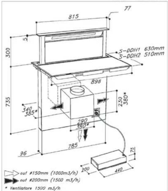
S-DDH1 Apertura Top: 860mm X 610mm Rectangular opening: 860mm X 610mm OH 2013
S-DDH2 Apertura Top: 860mm X 490mm
Rectangular opening: 860mm X 490mm
S-DDH
External motor
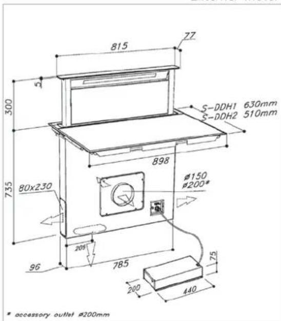
S-DDH1 Apertura Top: 860mm X 610mm Rectangular opening: 860mm X 610mm OH 2013
S-DDH2 Apertura Top: 860mm X 490mm Rectangular opening: 860mm X 490mm
natural_image
3D rendering of a white rectangular industrial machine with a handle and top panel (no text or symbols visible)natural_image
3D diagram of a white cabinet with red vertical supports and green horizontal bars, no text or symbols presentINSTALLAZIONE DOWNDRAFT
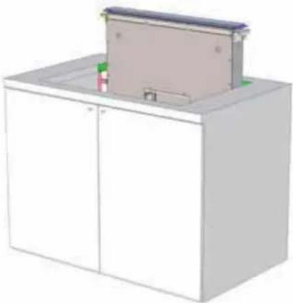
natural_image
3D rendering of a white cabinet with a mounted panel and green indicator lights (no text or symbols)natural_image
3D rendering of a white cabinet with a lid and internal compartments (no text or symbols visible)natural_image
Pure electrical circuit lines without any symbols0
Semivalore
Valore massimo

NOTA

chemical
Chemical reaction pathway diagram showing intermediates 6, P, A, and 5 with electron movement and proton transfersflowchart
graph LR
    G -->|+| P
    P -->|+| G
    G -->|+| P
    P -->|+| A
    A -->|+| G
    S -->|+| P
    P -->|+| G
    S -->|+| 3
    P -->|+| P
flowchart
graph LR
    G -->|+| P
    P -->|+| G
    G -->|...| P
    P -->|+| A
    A -->|+| G
    G -->|...| S
    S -->|+| P
    P -->|...| G
    G -->|...| S
    S -->|3| P
natural_image
Exterior view of a white industrial box with a black heart-shaped component on top (no text or symbols visible)The built-in ceramic-glass cooktop is intended for household use only. Materials used for packaging are nature friendly and may be recycled, deposited or destroyed without any threats to the environment. In order to recognize these features, all packing materials are marked with relevant symbols.
Once your appliance has become obsolete and you do not intend to use it any longer, take adequate care not to litter the environment. Deposit your old appliance with the authorized depot dealing with used household appliances.
INSTRUCTION FOR USE
Instructions for use have been prepared for the user, and describe the particulars and handling of the appliance. These instructions apply to different models from the same family of appliances, therefore you may find information and descriptions that may not apply to your particular appliance.
INSTALLATION INSTRUCTION
He appliance should be connected to the power supply in accordance with the instructions from the chapter “Electrical connections” and in line with the standing regulations and standards. The connections should be carried out by a qualified personnel only.
FIRE HAZARD PROTECTION
Appliances are allowed to be mounted on one side next to a high kitchen cabinet, the height of which may exceed that of the appliance. On the opposite side however, only a kitchen cabinet of equal height as the appliance is allowed.
CONTENTS
DEAR CUSTOMER! 41
INSTRUCTION FOR USE....41
INSTALLATION INSTRUCTION 41
FIRE HAZARD PROTECTION 41
COOKING HOB
IMPORTANT WARNINGS ABOUT THE COOKING HOB 44
IMPORTANT WARNINGS ABOUT THE DOWNDRAFT 46
TECHNICAL DRAWING 48
INSTALLATION SEQUENCE 49
INSTALLATION OF THE COOKING HOB WITH INTEGRATED DOWNDRAFT ....50
CONNECTION TO THE POWER SUPPLY....54
TECHNICAL INFORMATION....56
CERAMIC-GLASS COOKTOP 59
SAFETY FUNCTIONS AND ERROR SIGNALS ....70
CLEANING AND MAINTENANCE OF CERAMIC-GLASS HOB 72
DOWNDRAFT
USE....75
ELECTRICAL CONNECTION OF THE DOWNDRAFT 76
FUNCTIONS OF THE DOWNDRAFT....77
CLEANING AND MAINTENANCE OF THE DOWNDRAFT 79
OPERATIONAL ANOMALIES 80
AFTER SALES SERVICE....80
COOKING HOB
IMPORTANT WARNINGS ABOUT THE COOKING HOB
- The appliance may be built-in and connected to the power supply only by a qualified technician.
- Particular areas of the cooktop surface jacent to the hotplates) are hot during operation. Prevent the children to hang around the appliance and warn them properly against the danger of burns.
- Hot oil ignites readily, so be sure preparation of such food (fries) under stant control.
- Hotplates may not be left in operation empty, without any dishes on top.
- Never use the appliance for heating the ambience.
- Never use the ceramic-glass cooktop working surface. Sharp objects may damage the cooktop surface.
- Never place any metal objects upon the induction hotplate, such as knives, forks, spoons, pot lids, and the like, as they may get very hot.
- Preparation of food in aluminium or cookware is not allowed. Never place plastic objects or aluminium foil upon cooktop surface.
- In case any other appliances are plugged the electric mains close to the cooktop, prevent the contact of the plug cable with the hot cooking zones.
- Never keep any flammable or temper sensitive objects, like cleaning agents, sprays, detergents, etc., below the appliance.
- Never use cracked or broken cerami cooktop. In case you notice any visible cracks on the surface, cut the power supply immediately.
- In case of any malfunctions, disconnect appliance from the power supply and call service department.
- Do not use high-pressure steam cleaner hot steam to clean the appliance.
- The appliance is manufactured in compliance with the relevant effective safety standards.
- The appliance is not intended for use by persons (including children) with reduced physi-
cal, sensory or mental capabilities, or lack of experience and knowledge, unless they have been given supervision or instruction concerning use of the appliance by a person responsible for they safety.
- The hob can not be activated by external timers or remote controls systems.
- Be careful not to drop objects or crockery on the ceramic glass's surface. Even light objects (e.g. a salt shaker) can crack or damage the ceramic plate.
- If the appliance is built in over an (a pyrolytic system, it should not be operated) have the while the pyrolytic process is in progress because it can trigger the overheating protection of the cooktop.
- Don't connect the hob to the power with an extension cable or multiple sock because they don't assure a sufficient safety (e.g. overheating risk of multiple sockets).
As After using the cooktop, disconnect it from the user's interface. Do not trust the pot detector. - Connect the equipment to a permanent connection.
- Stationary appliances not fitted with means for disconnection from the supply mains having a plastic contact separation in all poles that provide full any disconnection under overvoltage category III, the instructions state that means for disconnection must be incorporated in the fixed wiring in accordance with the wiring rules.
- If the glass is broken, please disconnect not only the supply chain of the cooking appliance but that of the downdraft also.
This appliance can be used by children aged from 8 years old and persons with rec physical, sensory or mental capabilities or lack of experience or knowledge if they have been given supervision or instruction concerning use of the appliance in a safe way and understand the hazards involved. Children shall not play with this appliance. Cleaning and using maintenance shall not be made by child without supervision. - WARNING: Unattended cooking on a ho with fat or oil can be dangerous and may result in fire.
-
NEVER try to extinguish a fire with water, but switch off the appliance and then cover flame e.g. with a lid or a fire blanket
-
WARNING: Danger of fire: do not store items on the cooking surfaces.
- WARNING: Use only hob guards designed by the manufacturer of the cooking appliance or indicated by the manufacturer of the appliance in the instructions for use as suitable or hob guards incorporated in the appliance. The use of inappropriate guards can cause accidents.
- If the supply cord is damaged, it must be replaced by the manufacturer, its service agent or similarly qualified persons in order to avoid any kind of hazard.
- You may also find these instructional materials on the website of the manufacturer.
IMPORTANT WARNINGS ABOUT THE DOWNDRAFT
- It is designed to work in both suctioning mode, with outside evacuation, and filtering mode.
- These hoods have been designed for personal use in the home. The appliance used by adults. Make sure that the appliance is out of reach of children and that they do not use it to play with. Make sure that children do not operate the controls.
- When the appliance is delivered, overall appearance of the packaging.
Any remarks should be written on the delivery coupon, of which you keep a copy.
Your appliance is designed for normal domestic use. It is not designed for commercial or industrial use, or for purposes other than those for which it was designed.
- Any consequences of or damage from incorrect installation or incorrect use of the appliance will not be covered by the manufacturer's guarantee.
- Do not ever change or try to change the characteristics of this appliance. This would be a danger. Repairs must be performed an authorised technician.
Always disconnect the hood before out cleaning or maintenance operations.
- Adequately ventilate the room when a cooker hood and other appliances, powered by energy other than electricity, are used neously, so that the hood does not suck any combustion fumes.
- It is not allowed to cook food flames (flambé) or operate gas hobs without pots or pans on them under the (the flames sucked into the hood might damage the appliance).
- Frying under the appliance must be done under constant supervision as hot oils and fats may ignite.
Respect the guidelines for cleaning placement of grease filters. Accumulated deposits of grease are a fire hazard.
- This appliance must not be used over tops powered by wood or coal or in any case, over cook tops with power levels that could damage the appliance. Never use steam or high-pressure devices for cleaning your hood (regulations regarding electrical safety).
- Never use the cooker hood without the grease must be filters.
- The minimum distance between the Dow draft (closed) and the surface above it must be at least 400 mm.
- When handling the downdraft, never put your hands in the field of action of the extractable unit.
- This appliance can be used by children aged from 8 years old and persons with rec physical, sensory or mental capabilities or lack of experience or knowledge if they have been given supervision or instruction concerning use of the appliance in a safe way and understand the hazards involved. Children shall not play with this appliance. Cleaning and u maintenance shall not be made by child without supervision.
- NEVER try to extinguish a fire with water, but switch off the appliance and then cover flame e.g. with a lid or a fire blanket.
only
carrying
If the supply cord is damaged, it must be replaced by the manufacturer, its service agent or similarly qualified persons in order to avoid a hazard.
- CAUTION: This appliance is not intended to be used with gas hobs.
- If the supply cord of the appliance is provided with a hob, this must be easily accessible.
over
• You may also find these instructional materials open on the website of the manufacturer.
hood itself
and re-
Constantly seeking to improve our products, we reserve the right to modify their technical, functional, or aesthetic characteristics deriving from their upgrading.
The air collected must not be conveyed into a flue used for smoke or fumes from appliances powered by anything other than electricity (central heating systems, etc.).
As far as discharging exhaust air is concerned, please follow the guide- lines given by competent authorities.
In the case of the version with external motor, for normal downdraft operation, it is necessary to use a suctioning unit (external motor) made by the same manufacturer.
Keep these instructions for use with the appliance. If the appliance should be sold or passed on to others, make sure that the instructions are passed on with it.
We thank you for taking note of these suggestions be- fore installing and using the appliance. They have been written for your personal safety and the safety of others.
natural_image
Symbol of a trash bin crossed out by a diagonal line, with no text or numbers present.The symbol on the product or on its packaging indicates that this product may not be treated as household waste. Instead it shall be handed over to the applicable collection point for the
recycling of electrical and electronic equipment. By ensuring this product is disposed of correctly, you will help prevent potential negative consequences for the environment and human health, which could otherwise be caused by inappropriate waste handling of this product. For more detailed information about recycling of this product, please contact your local city office, your household waste disposal service or the shop where you purchased the product. This appliance is marked according to the European directive 2002/96/EC on waste electrical and electronic equipment (WEEE).
TECHNICAL
DRAWING
S-DDH
Motor on board
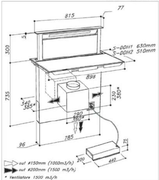
S-DDH1 Apertura Top: 860mm X 610mm Rectangular opening: 860mm X 610mm OH 2013
S-DDH2 Apertura Top: 860mm X 490mm
Rectangular opening: 860mm X 490mm
S-DDH
External motor
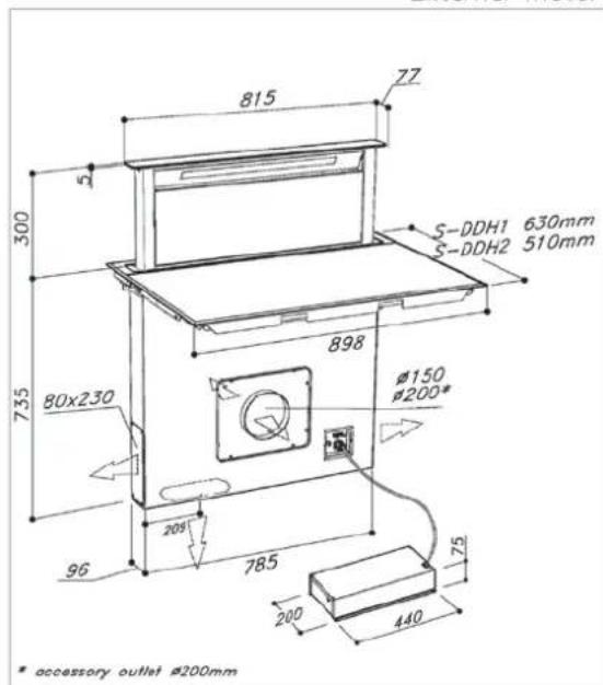
S-DDH1 Apertura Top: 860mm X 610mm Rectangular opening: 860mm X 610mm OH 2013
S-DDH2 Apertura Top: 860mm X 490mm
Rectangular opening: 860mm X 490mm
HOLE CUT FOR INSTALLING THE HOB
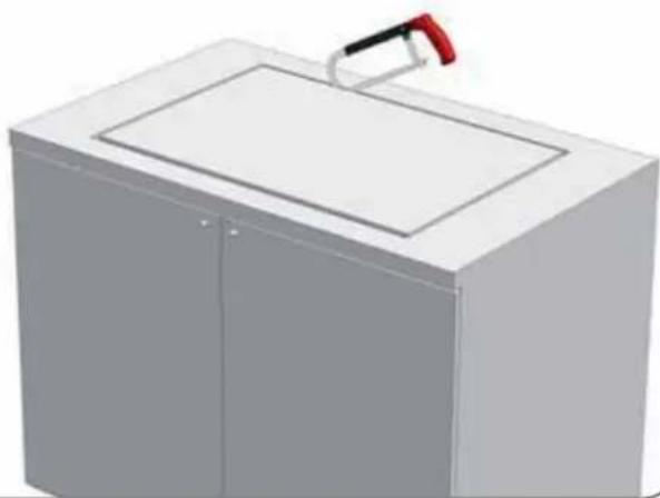
natural_image
3D rendering of a rectangular industrial or laboratory appliance with a handle and lid (no text or symbols visible)INSERTION OF THE METAL
INSTALLATION STRUCTURE
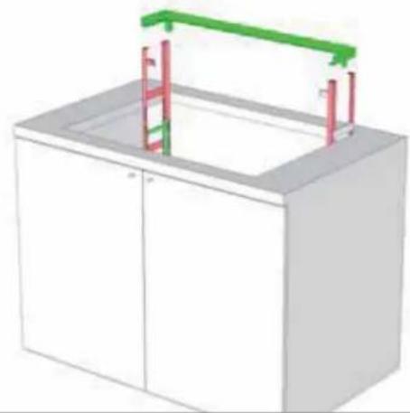
natural_image
3D diagram of a white cabinet with red vertical supports and green horizontal bars, no text or symbols presentDOWNDRAFT INSTALLATION
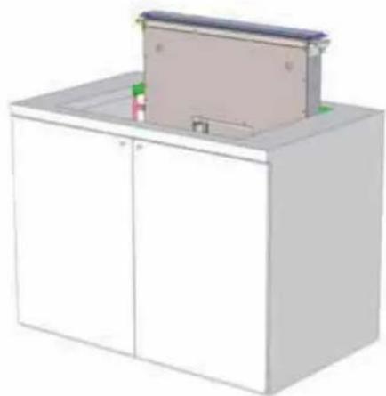
natural_image
3D rendering of a white cabinet with a mounted rectangular panel (no text or symbols visible)COOKING HOB INSTALLATION
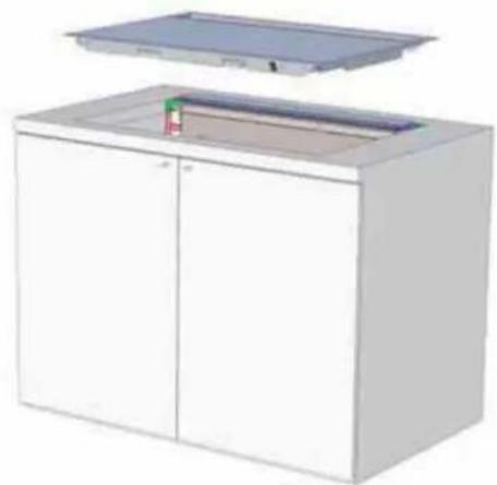
natural_image
3D rendering of a white cabinet with an open lid and internal compartments (no text or symbols visible)INSTALLATION OF THE COOKING HOB WITH INTEGRATED DOWNDRAFT
CAUTION!
- The installation and the connection product to the mains electricity must only be carried out by qualified personnel.
- The kitchen unit into which the product is to be installed must be realised in materials (including adhesives and finishes) that are resistant to a temperature of 100^ C.
- After the installation, the product must be accessible for any eventual technical i tions.
- All wall units above the product must be positioned at a height that does not disturb work processes.
- The cornice of the worktop can have a thickness greater than the worktop because opening is maintained in the front part of the kitchen unit of at least 5mm (refer to de below) to ensure an adequate passage of air to avoid overheating the product.
- Before cutting the hole, check inside kitchen unit where the product will be housed to ensure that there are no obstructions such as parts of the unit's structure or anything else that could cause problems for a correct installation. Check that the overall dimension the downdraft and the cooking hob are compatible with the kitchen furniture so installation is feasible.
- Induction hob may be built into the 25 to 40 mm thick worktops.
BUILT-IN INDUCTION HOB OPENING DIMENSIONS
of
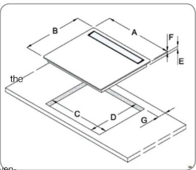
| S-DDH1 | S-DDH2 | |
| A (mm) | 898 | 898 |
| B (mm) | 630 | 510 |
| C (mm) | 860 | 860 |
| D (mm) | 610 | 490 |
| sign E (mm) | 45 | 45 |
| F (mm) | 5 | 5 |
| the G (mm) | 50 | 50 |
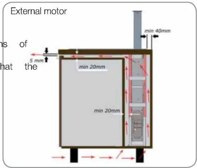
Internal motor
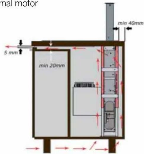
- A horizontal and vertical space of 20mm from the lower surface of the cooking hob and at least 20mm from the must be foreseen so as to create a passage for the air necessary to cool the product (refer to the above illustration).
- There must be an opening of at least 50mm the whole width of the kitchen unit in the lower and rear part of the furniture to allow for the passage of air to avoid the product overheating.
- Ensure that the passage of air in the lower part of the kitchen unit permits a constant flow of air to cool the product.
- Fitting the oven underneath the cooking hob is possible with fan-cooled ovens. Before installing the oven, remove the rear wall of the kitchen unit where the oven will be fitted into the kitchen furniture.
There must also be a minimum a 5mm in the front part and above all in the lower part of the kitchen furniture to adequate passage of air necessary to cool the product.
Before installing the product, check that all components are not damaged. If any cost are damaged, contact the retailer and do not go ahead with the installation.
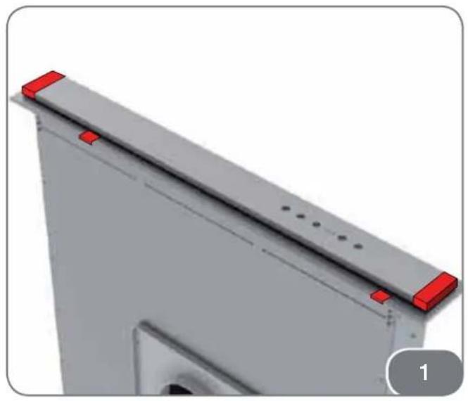
Before installing the downdraft, remove the safety spacer highlighted in the photograph (Fig. 1).
Furthermore, carefully read all the instructions as follows:
- Utilise an air extraction duct that has a maximum length of not more than 5 metres.
- Limit the number of curves in the cause each curve reduces the efficiency of the extraction equal to 1 linear metre (E.g., if two 90^ curves are utilised, the length of the duct must not exceed 3 metres in length).
- Avoid drastic changes of direction.
- Utilise a duct with a 150mm or 200mm diameter along its whole length.
- Utilise a duct that is manufactured from material approved to the norm. The sup company will not respond to problems of flow capacity or noise if there is a lack of respect of the previously mentioned instructions and the guarantee will be annulled.
downdraft
-
Position the support bracket of the draft in the rear part of the realised aperture (refer to Fig. 2).
-
The bracket must be positioned approximately two/three millimetres from the upper surface of the worktop, as shown in Fig.3.
-
Fix the support bracket of the downdraft to the worktop by utilising the screws supplied in the case of wood worktops. For worktops realised in materials different to wood, utilise the appropriate screws.
-
Utilise the upper and lower holes positioned in the support bracket of the downdraft in accordance with the thickness of the worktop into which the product is installed.
-
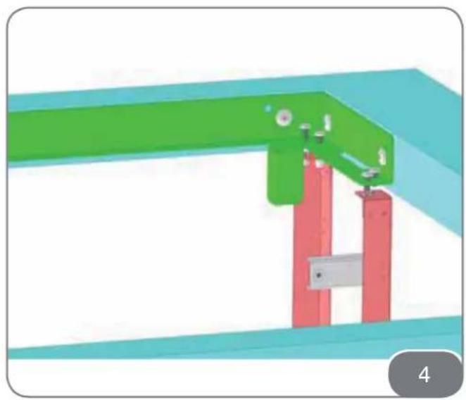
Fix the two worktop reinforcement telescopic structure of structures to the lower sides of the support bracket of the downdraft, as shown in Fig. 4.
ensure an 6. After fixing the reinforcement structures, adjust their telescopic travel so as to reach the base underneath (Fig. 5). Fix the structure to the base underneath utilising the supplied.
-
Check that the worktop is perfectly level block the travel of the structures utilising the four self-threading screws, positioned as in Fig. 6.
-
Insert the downdraft into the installed port bracket (refer to Fig. 7). The fix positioned on the downdraft must coir perfectly with the support bracket installed in the kitchen unit (refer to Fig. 8).
-
Install the cooking hob ensuring opening at the rear of the product coincides perfectly with the downdraft (refer to Fig. 9).
that INSTALLING THE FOAM GASKET
Before installing the cooking hob in its appropriate seat in the worktop, apply the adhesive gasket in expanded polyurethane supplied with the product to the lower part of the cooking hob.
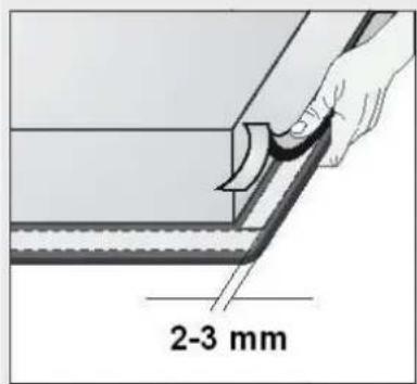

Do not install the cooking hob without the adhesive gasket!
The gasket should be attached to the appliance in the following way:
- Remove the protective film from the gasket.
- Then, attach the gasket to the lower side of the glass, approximately 2-3 millimetres from the edge.
- The gasket must be attached along the entire length of the glass edge and should not overlap at the corners.
- When installing the gasket, make sure that the glass does not come into contact with sharp objects.
INSTALLATION PROCEDURE
• The worktop must be perfectly level.
- Put the supplied springs in their places.
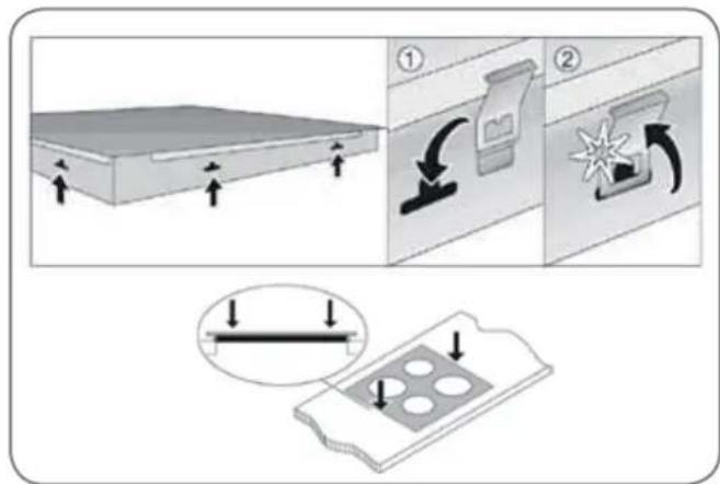
- Place the cooking hob into the previously realised opening in the worktop.
- Press the cooking hob down forcefully the worktop, in correspondence to the edges of the cooking hob.
If the downdraft is not perfectly aligned with the cooking hob, adjust the adjustment screws (Fig. 10A) on the right and left of the product. Screw in the screws to lift the downdraft and unscrew to lower the downdraft.
Before the installation, the screws indicated in
Fig. 10B must be unscrewed as much as possible so as to keep the downdraft near to the rear part of the kitchen unit.
If the downdraft is not centred correctly with the cooking hob after the installation has been carried out, utilise the adjustment screws (Fig. 10B) to shift it forwards by screwing in the screws or backwards by unscrewing the screws the right and left side of the product.
-
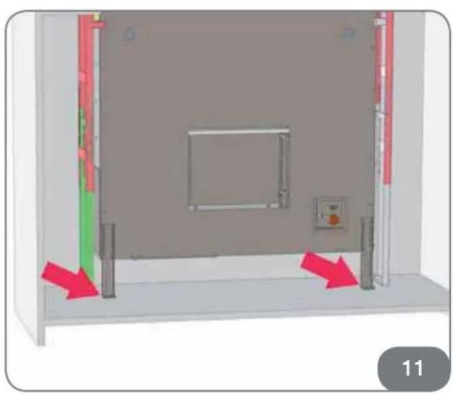
Check that the downdraft inside the kitchen unit is perfectly vertical. Fix it utilising the brackets supplied (Fig. 11).
-
Permanently block the downdraft utilising the two screws indicated in Fig. 12.
-
Connect the electrical cables of the down-draft as shown in Fig. 13 and then carry out the connection to the mains electricity in ac-
cordance with the information reported the relative technical data plate.
-
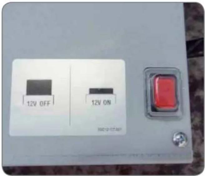
After completing the installation and h connected the downdraft to the mains elec- tricity, check that the red key on the electron- ic metal box is pressed and then activate the lifting of the extraction carriage by pres the ↑↓ key.
-
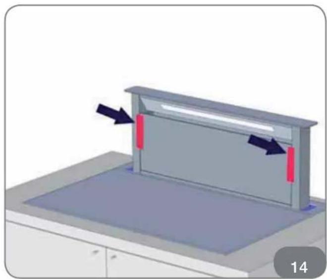
When the extraction carriage is fully opened, remove the door block (Fig. 14). Successively open the door (Fig. 15) and positi anti-grease filters (Fig. 16).
-
The motor can be installed on the rear part of the downdraft. The air outlet must be pointed upwards or downwards.
-
Assemble the ducting for the air outlet.
-
In the case of the version with air motor, choose the air outlet most su from the five possibilities (refer to the design y onthe TECHNICAL ILLUSTRATION chapter) and install the supplied union.
-
Position the metal box containing the tronic components in an easily accessi position in the case of any technical interven- tion.
CONNECTION TO THE POWER SUPPLY
- Connections may be carried out by a qualified technician only. The earthing protection must comply with the standing regulations.
- Connection terminals are revealed when connection box cover is removed.
- Prior any attempted connection check the voltage indicated on the rating plate is in line with your home power supply.
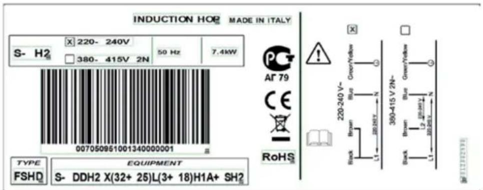
- The rating plate is located underneath the appliance.
• The cooking hob operates at 220V-240V\~. - In order to make a fixed connected mains, insert an all-pole circuit breaker between the appliance and the mains. device shall have a contact separation poles, providing full disconnection under over-voltage category III conditions.
- Such appliances are allowed to be mounted on one side next to a high kitchen cabinet, the height of which may exceed that of the appliance. On the opposite side however, kitchen cabinet of equal height as the appliance is allowed.
- Upon the completion of installation, live wires and isolated cables must be adequately protected against accidental touching.
BASIC ADJUSTMENT OF SENSORS TO THE AMBIENCE
Upon each connection to the power supply the sensors of the appliance are automatic, justed to the environment to ensure their proper function. All displays turn on and are fully illuminated for a few seconds.
During the adjustment procedure the must be free of any objects, otherwise the justment procedure will be interrupted until such objects are removed from the sensor. During this period the regulation of the cooktop is impossible.
WARNING
Before attempting any repairs on the appliance, disconnect the power supply. In accordance with the mains voltage the appliance should be connected in line with the attached diagram. The earthing wire (PE) must be connected to the terminal marked with the earthing symbol.
The connection cable must lead through the relief safety device, protecting it from accidental pulling out.


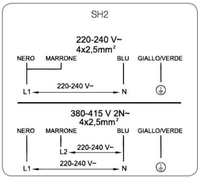
INSTALLATION DIAGRAM:
tion to the
The induction cook-top is supplied without pow-
er.cable.
For the connection please use cable like:
• "H05RR-F
H05RN-F
H07RN-F
• (Never use cables (FROR) type.
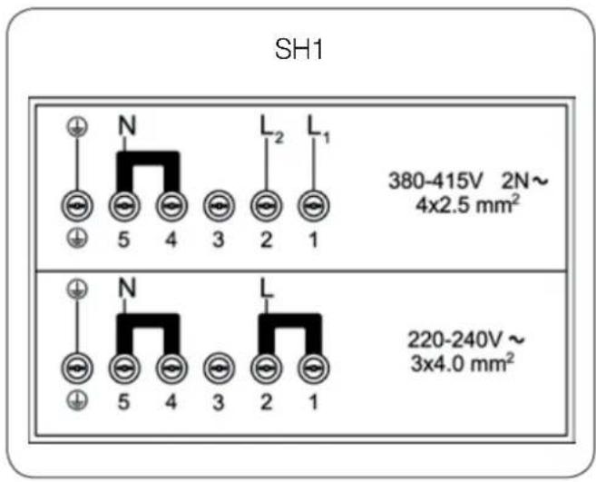
only a The cable needs to be connected on the terminal board directly as per the information included both in the rating plate and in the electrical scheme you can find here below.
The transformation from a two-phase into a single-phase or vice versa needs to be carried out through the jumpers placed in the terminal board.
In the model SH2 with the cable included connection needs to be made on the terminals of adhe power cable directly during the connection with the electrical net as you can find both in the rating plate and in the electrical scheme here below.
ad upon the completion of installation switch all the hotplates on for about 3 minutes to check supaper functioning.
TECHNICAL INFORMATION
| S-H1 S-H2 | ||
| Width (mm) | 898x630 898x510 | |
| Rated voltage | 220-240V~ o 380-415V 2N~, 50/60 Hz | |
| Type of switch | Electronic sensors | |
| Cooking zones (∅, mm/kW) | ||
| Forward left | 184x220, 2,1(P=3,7) | 184x220, 2,1(P=3,7) |
| Rear left | 184x220, 2,1(P=3,7) | - |
| Forward central | 184x220, 2,1(P=3,7) | 184x220, 2,1(P=3,7) |
| Rear Central | - | - |
| Forward right | - | 184x220, 2,1(P=3,7) |
| Rear right | 184x220, 2,1(P=3,7) | - |
| Total power (W) | 7400 7400 | |
P= Extra powerful setting
HOTPLATE FUNCTION PRINCIPLE
- Ceramic glass hob is fitted with three or four hotplates. Hob surface is completely flat and smooth, without edges to accumulate dirt.
- The cooking hob is equipped with a functional induction cooking zone. The formed directly in the bottom of the cooking pot.
This way the required extent of energy considerably smaller compared to traditional heaters, which operate on radiation principle.
- Glass ceramic hotplate is not heated ly, but only by return heat transmitted by the dish. This heat figures as “remaining after the hotplate is turned off. The induction hotplate generates heat from the incoil, installed underneath the ceramic glass surface. The coil stabilises the magnetic field.

In case sugar or other heavily sweetened substance is spilled on the hotplate, wipe it immediately and remove the sugar residues with a scraper although the cooking zone is still hot, otherwise the hotplate may be damaged. Avoid cleaning the cooktop while the cooking zones are still hot, as you may damage the hob.
APPROPRIATE COOKWARE FOR INDUCTION HOTPLATES
natural_image
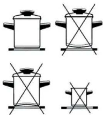
Four identical line drawings of cooking pots with crossed x marks, no text or symbols present- Induction hotplate will function perfectly only if appropriate cookware is used.
- Dish should be in the middle of the hotplate during cooking.
- The appropriate cookware is the one when enables induction, for example steel, enamel, high-steel alloy cookware. Pots made from steel at alloy with copper or aluminium bottom, glass pots are inappropriate.
gy Ifs you use the pressure cooker ("econd pot") keep it under close surveillance un proper pressure is obtained. Hotplate should first operate on maximum power, then follow the manufacturer's instructions and use the appropriate sensor to decrease the power.
- When buying cookware, check if it be tion the label "allows induction".
| Cooking zones | Min. pan bot- tom ∅ min. | Max. pan bot- tom ∅ | |
| 184x220 mm (SINGLE) | ∅ 115 mm ∅ | 180 mm | |
| 184x220 mm (SINGLE) IN BRIDGED MODE | ∅ 135 mm | ∅ 180 mm | |
| 184x220 mm (DOUBLE) IN BRIDGED MODE | 2 ZONES | - | 380x220 mm |
| 4 ZONES | ∅ 330 mm | ∅ 400 mm | |
Magnet test
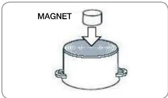
Use small magnet to test if the dish magnetic. Only dishes where magnet stick the bottom are suitable for induction cooking.
Dish recognition
One of great advantages of the induction plate is dish recognition. Even if there dishes upon the hotplate, or the dish dia is smaller than the diameter of the relevant hot-plate, there are no thermal energy losses. When the hotplate is on, the power indicator displays letter "U". If you place the dish over that hotplate within the following 10 minutes, the hot recognizes the dish and turns on to the preset power value.
At the moment you remove the dish from the hot-plate, power is suspended. If you place smaller dish upon the hotplate and it is recognized, the hotplate will only use the amount of energy required to heat the dish according to its size.
Hotplate may be damaged if:
- it is turned on and left empty, or an empty dish is placed on it;
- You use clay dishes which leave scratches on the ceramic glass surface;
- You fail to wipe the dish bottom dry prior placing it on the ceramic glass hotplate; heat induction is obstructed and the hotplate may be damaged;
- You fail to use the appropriate dishes that can be magnetized: steel dishes, enamel or steel alloy dishes; induction hotplate will not function otherwise.
POWER REGULATION
Heating power of the hotplates may be nine different levels.
The following chart indicates illustrative use of each power setting.
| Power Setting | Purpose |
| 0 bottom | Off, using remaining heat |
| ks to 1-2 | Maintaining warm food, slow simmer of smaller quantities |
| 3 | Slow simmer (continuation of cooking after a powerful start-up) |
| n hot-are 4-5 no ameter | Slow cooking (continuation) of larger quantities, roasting larger chunks |
| 6 | Roasting, browning |
| 7-8 | Roasting |
| 9 | Start of cooking, roasting |
| A | Automatic initial setting |
| plate P | Especially powerful setting for e tremely large quantities of food |
ENERGY SAVING TIPS
- When buying cookware be careful in ing size: pot diameter usually refers to the top edge of the dish, which is often larger than the dish bottom.
Steam-pressure pots (economic pots), which use pressure in tightly sealed interior, are especially economic, and save both time and energy. Shorter cooking time leaves more vitamins in food.
• Always leave enough water in steam-pressure pots, otherwise it may result in overheating which may damage both the pot and the hot-plate.
- Always cover the cookware with lids of appropriate size.
• Use such dish size to accommodate the
quantity of food to be prepared. If you use excessively large pot for small amount of food, you will consume considerably more energy.
select-
CERAMIC-GLASS
COOKTOP
flowchart
graph TD
    A["1"] --> B["2"]
    B --> C["3"]
    C --> D["5"]
    D --> E["7"]
    E --> F["8"]
    style A fill:#f9f,stroke:#333
    style F fill:#bbf,stroke:#333
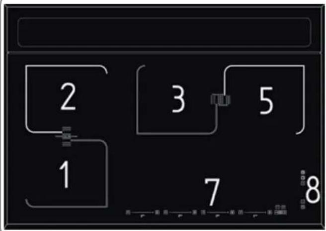
- Induction hotplate front left
- Induction hotplate rear left
- Induction hotplate rear central
- Induction hotplate front central
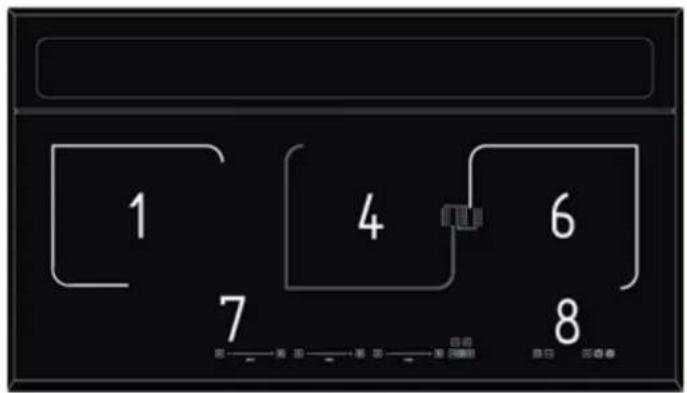
- Induction hotplate rear right
- Induction hotplate front right
- Hob control panel
- Downdraft control unit
HOB CONTROL ELEMENTS

A. ON/OFF sensor of cooktop
B. Safety lock on/off and child lock sensor
C. Pause and recall function sensor
D. Sensor (-) of timer
E. Sensor (+) of timer
F. Warming function sensor
G. Slide control
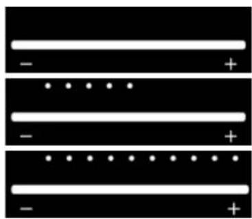
SLIDE CONTROL POWER
natural_image
Pure electrical circuit lines without any symbols0
Medium power
Full power
HOB CONTROL
- After turning the ceramic glass hob on all displays come on for a moment. The hob is ready for operation.
- The hob is fitted with electronic sensors which are switched on if you touch the relevant circle for at least one second.
• Each sensor activation is followed by a sound signal. - Avoid placing any objects on sensor surface (possible error signalization).
• Always keep the sensor surface clean.
ACTIVATING THE HOB
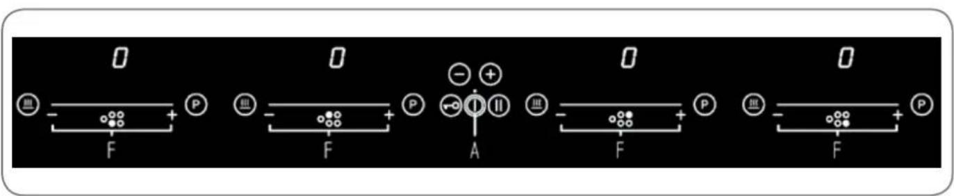
- Touch the (A) sensor for at least one second.
• The hob is now active, and all hotplate power indicators indicate »0«.

NOTE

Now you need to select the next setting within 10 seconds, otherwise the hob switches off again.
TURNING HOTPLATES ON
- If you have switched on the cooking hob by utilising the sensor (A), the required cooking zone can be chosen within the next 10 seconds.
- Set the power level 1-9 by touching the slider (F).
- At the first touch, the level is set according to the part of the slider that you touch. Upon the slider, the control LEDs light up, according to the level set. By sliding along the slider, the power level setting is changed. By sliding to the right, the level increasing, while sliding to the left decreases the level. When you move your finger away from the slider, the cooking field starts to operate at the level set.
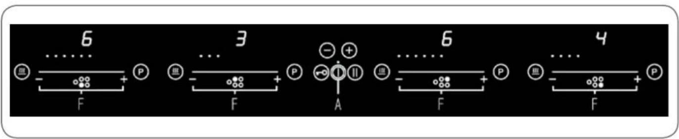
If a specific point of slide control is pressed for at least 3 seconds, the automatic cooking is activated (see Automatic fast heating).
Changing hotplate power settings
- By touching or sliding along the slide sensor (F) you change power setting.
- When you remove the finger from the slide sensor, the hotplate starts to operate at selected power.
SWITCHING HOTPLATES OFF
- Selected hotplate must be activated.
- By touching the slide sensor (F) at the start, bring the power setting to "0". Short beep confirms the OFF position.
SWITCHING THE HOB OFF
• The hob is switched off by pressing the main (A) sensor.
- The sound signal beeps and all indicators go off, except for those hotplates which are still hot and display the warning "H" sign as an indication of the remaining heat.
- If you switch the hob off prior end of cooking session, use the remaining heat and save electric energy.
LOCKING THE CONTROL UNIT
By activating the key lock protection you can stop the operation of the appliance and the use of hotplates.
Activating the control unit lock
- The cooktop must be turned on.
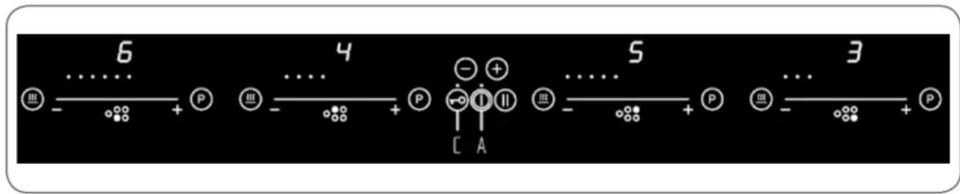
- Press the sensor (C) for approximately 1 second, the corresponding LED turns on above the key, the block is active.
- Safety lock prevents the activation of all sensors, except for (A) and (C) sensor.
- If the hob is switched off when the lock function is activated, it remains in memory until a new switches the hob.
- When set timers end their time, alarms can be switched by activating (D) or (E) keys without need for unlocking the control.
Deactivating the control unit lock
• The cooktop must be turned on
- Press the sensor (C) for 1 second; after that, the unlocking is confirmed by a beep.
PAUSE FUNCTION

NOTE

The execution of the function is only possible if at least one zone is on.
The pause condition may also be activated with cooking zone specific errors, here, the error display is hidden. Also residual heat indication, special messages such as A, P or no pan are hidden; the pause display has priority. If there is a general error during the pause, the control switches off and terminates the mode.
Activating the Pause function
- Press the sensor (B) for at least 1 second, the corresponding LED turns on above the key and all displays show the symbol "II".
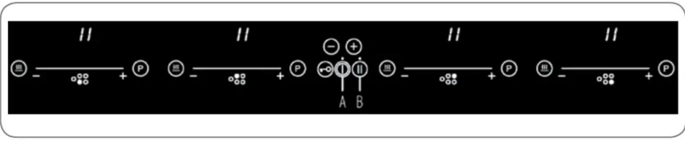
While the Pause function is active:
- Any Timer (also Egg-timer) set before the pause will be stopped during the pause and continue when pause mode is quitted.
• A selected booster or heat up time automatic function is terminated. - Residual heat calculation and maximum operation time limitations will not be interrupted and keep on working in the background.
Functional LED's such as Timer, multi-zone, keep on glowing according to their status.

NOTE

The pause mode can only be active for maximum 10 min. If the pause mode is not deactivated within 10min the control switches off automatically.
Throughout the pause time the (A) button can be used to switch the control off. In this case the pause mode is also deactivated.
Deactivating the pause mode:
- Press the (B) followed, the LEDs light up above the cursor of one of cooking zones.
- Within 10 seconds press and scroll from the left to the right on the cursor of the illuminated area.
The LED above the pause key turns off and the condition before the pause mode is restored.
RECALL FUNCTION
If the control was accidentally switched off through the main switch (A) all settings can be restored using the recall function. After switching the control off from the main switch the user has 6s to switch the control on again and then he has another 6s to press the pause button (B) in order to recall the settings. The recall function can only be used if at least one cooking zone was active (cooking level >0) independent from key lock.
REMAINING HEAT INDICATOR
Glass ceramic hob also features remaining heat indicator "H". Hotplates are not heated directly, but through return heat radiating from the dish.
As long as the symbol “H” is on after the hotplate was switched off, the remaining heat may be used for warming up food or for melting.
Even when the symbol "H" disappears, the hotplate may still be hot.

Be careful of burns!
EXTRA POWERFUL SETTING
(HOTPLATES MARKED "P")
Extra powerful setting may be additionally switched on for fast cooking on indicated hotplates. This extra hotplate power is used for heating large quantities of food.
After switching on, the extra power is activated for 10 minutes then automatically switches back on to the maximum normal level 9.
During the time extra power is activated, the power of other hotplates is limited. This is indicated on the power display by intermittently flashing the selected cooking level and limited power for a few seconds.
Activating extra powerful setting
- Press the (H) sensor of the required cooking zone, the extra cooking is active. The display shows "P".

flowchart
graph LR
    A["6"] --> B["−"]
    B --> C["+"]
    C --> D["P"]
    D --> E["−"]
    E --> F["+"]
    F --> G["P"]
    G --> H["−"]
    H --> I["+"]
    I --> J["P"]
    J --> K["−"]
    K --> L["+"]
    L --> M["P"]
    M --> N["−"]
    N --> O["+"]
Premature turning extra powerful setting off
- Press and scroll on the cursor of the wanted zone, until you get to "0" if you want to turn off the zone, or until the wanted cooking level.
HEAT UP TIME AUTOMATIC
When automatic cooking mode is activated the hotplate will operate at maximum power for a limited period of time and then automatically switch to the reduced power level to resume cooking. It may be switched on in any of the hotplates for all power settings except for setting "9" where power is set at maximum all the time.
Automatic cooking mode is activated on any idle hotplate.
- Choose the required continuous cooking level and hold it for 3 seconds.
- The activated heat up time automatic will be displayed through alternating between „A” and the selected continuous cooking level on the display.
As soon as the parboiling time is over, the preselected continuous cooking level is valid again.
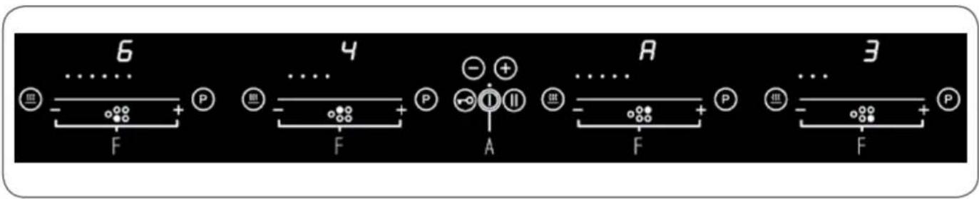
Once the time from the chart below expires, the function is switched off and "A" disappears. You can also switch the automatic cooking mode off anytime by bringing power setting to "0".
With the bridge function two separate cooking elements /inductors with the same diameter and equal power can be turned on at the same time and controlled with only one operation.
Activating Bridge Function
Whether the two zones are working at a different level, whether they are at level 0:
- Simultaneously press anywhere on the slider (F) of the zones:
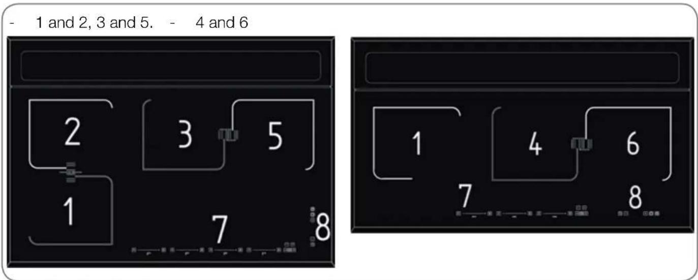
- Now the two areas work together, the LEDs to the right of the corresponding displays turn on. The level is shown on the display of the control zone, in the meanwhile the controlled zone's display turns off.
- When this function is active, you can set the timer, the LED lights on near both displays of the zones, moreover it's not possible setting a particularly powerful cooking function.

- If in 10 uninterrupted minutes no cookware is detected on one of the two elements, the bridge function is automatically deactivated, the uncovered cooking element is switched off and the covered cooking element remains as the single cooking element switched on with the set cooking level.
Deactivating Bridge Function
- The end of the Bridge Function can be done by repeating the simultaneous selection of both cooking elements (the same as activation).
If the bridge function is deactivated while in operation, than both cooking elements go to level "0" and can then be set again.
WARMING FUNCTION
The warming function is used to keep cooked food warm.
Hence this function can also be used as melting or simmer function.
Activating heating function:
- Pressing the special function key (G) of a cooking zone activates the "melting" function. The first LED is activated.
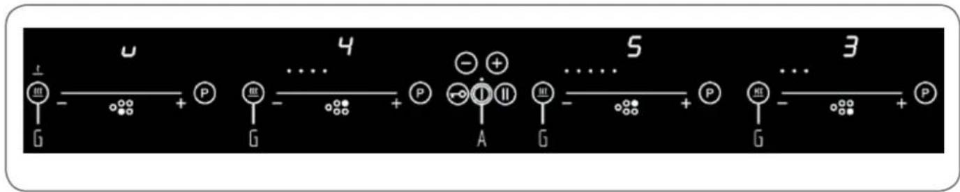
flowchart
graph LR
    G -->|+| P
    P -->|+| G
    G -->|+| P
    P -->|+| A
    A -->|+| G
    S -->|+| P
    P -->|+| G
    S -->|+| 3
    P -->|+| G
- If the special function key is pressed a second time “warming” level two is activated. The second LED is activated.
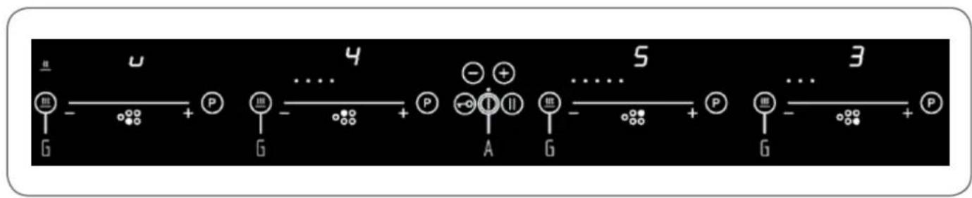
flowchart
graph LR
    G -->|u| + P
    P -->|P| + P
    P -->|P| + A
    A -->|S| + P
    P -->|S| + G
    G -->|3| + P
- If the special function key is pressed a third time “simmering” level three is activated. The third LED is activated.

flowchart
graph LR
    A["输入"] --> B["-"]
    B --> C["+"]
    C --> D["P"]
    D --> E["输出"]
    E --> F["..."]
    F --> G["4"]
    G --> H["-"]
    H --> I["+"]
    I --> J["P"]
    J --> K["..."]
    K --> L["5"]
    L --> M["..."]
    M --> N["3"]
    N --> O["+"]
    O --> P["P"]
If the special function key is pressed a fourth time the warming function ends.
SAFETY SWITCH OFF
Maximum continuous operation of a particular hotplate is limited, and the duration is displayed in the above chart. When the hotplate is switched off by the safety mechanism, the indicator displays symbols "0", or "H" in case there is any remaining heat left.
In such cases switch the hotplate off by touching the slide sensor (F) at the start, bring the power setting to "0".
| Power setting | 1 | 2 | 3 | 4 | 5 | 6 | 7 | 8 | 9 | |
| Hours lapse prior safety switch off | 6 | 6 | 5 | 5 | 4 | 1,5 | 1,5 | 1,5 | 1,5 | |
Example: Set the hotplate to power level 5 and leave it operate for some time. If you do not change the above setting, the safety mechanism will switch the hotplate off after 4 hour.
PROTECTION FROM OVERHEATING
Induction hotplate is also fitted with safety device against overheating which protects electronic parts from damages. This device operates on several levels. When temperature of the hotplate excessively rises, it switches on two-stage fan. If this is not enough, extra powerful heating is deactivated, and finally the safety device either reduces the heating power of certain hotplates or turns them off completely. When the hotplate cools off, the full power of hotplate is again available.
TIMER
Use of timer facilitates cooking by setting the time of hotplate operation.
Turning timer on
• The cooktop must be turned on and the zone where you want to set the timer must be working.
- Simultaneously press sensor (D) and (E), the timer's display shows "0.00", and the LED to the right of the display, of the first active cooking zone from the left, lights on.
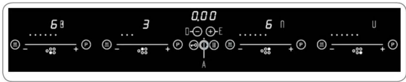
- Simultaneously press (D + E) as many times as necessary, to select the zone where you want to set the timer. The LED lights on only for the active cooking zones.
- Within 10 seconds since pressing the (D + E) set the timer value by pressing the sensors (D) or (E) .
- The value of the timer can be displayed:
- in minutes and seconds up to 9min 59sec;

- in hours and minutes up to 9h 59min, in this case the word "min" is shown under the timer's display.


Operation time can be set for each hotplate separately.
Changing preset cooking time
- Cooking time can be changed anytime during the operation.
- Simultaneously press sensor (E) and (D).
- Simultaneously press (D + E) as many times as necessary, to select the zone of which you want to adjust the timer. The zone is identified by the lighting on of the LED to the right of the display.
- Press the sensors (D) or (E).
- If time is not modified in 10 seconds since pressing the sensor (D+E), the timer is keeping the count-down before the adjusting operation.
Checking remaining cooking time
- Last set timer is always displayed, (the LED to the right of the display of the cooking zone in question has a lighting stronger than the others).
- Simultaneously press sensor (E) and (D).
- Simultaneously press (D + E) as many times as necessary, to select the zone of which you want to see the remaining time. The zone is identified by the lighting on of of the LED to the right of the display.
- The timer's display will display the remaining time of the selected cooking zone.
Turning timer off
When preset time elapses, a beep signals the end, and the hotplate is switched off.
Switch off the alarm by pressing the sensor (D) or (E) or it switches off automatically after 2 minutes.
If you want to switch off the timer prior the end of preset time:
- Simultaneously press sensor (E) and (D).
- Simultaneously press (D + E) as many times as necessary, to select the zone of which you want to disable the timer. The zone is identified by the lighting on of the LED to the right of the display.
- Press (D) to the value "0".
- The illuminated point to the left part of the display is turned off and the timer is deactivated.
ALARM TIMER FUNCTION
Timer can be used as alarm also if it is already employed in timer control of one of the hotplates.
Timer setting
With the hob off:
- Touch the sensor (A) to activate the cooking hob.
• Simultaneously press sensor (E) and (D) to activate the alarm.
The timer's display shows "0.00" and:
- If some cooking zone is active: the LED to the right of the display, of the first active cooking zone from the left, lights on.

Simultaneously press (D + E) as many times as necessary to select the alarm. The respective LED is located between the keys (E) and (D) .
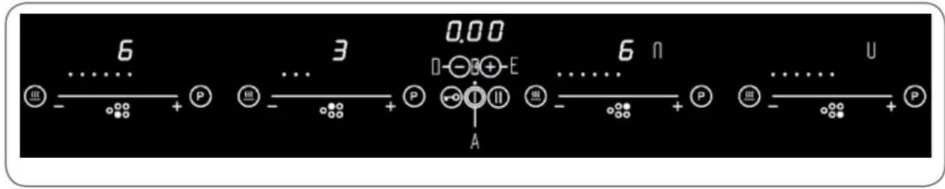
- If no cooking zone is active: the alerter's LED lights on.
• The timer value is set by pressing sensors (D) o (E).
It's possible setting time in seconds and minutes also for the alerter:

or in hours and minutes.

Switching the alarm off
When the preset time expires a beep is heard which you can either turn off by touching the (D) or (E) sensors, or leave it to turn off automatically after 2 minutes.
If you want to switch the timer off prior expiry of preset time:
• Simultaneously press sensor (E) and (D).
- Simultaneously press (D + E) as many times as necessary to select the alerter, the respective LED lights on.
- Press (D) until the value »0«. The alerter is deactivated.
SAFETY FUNCTIONS AND ERROR SIGNALS
| ERROR CODE ERROR | DESCRIPTION INSTRUCTION MANUAL | |
E03 + continuoustone, or | Permanent use of keys; Control unit cuts off after 10 sec. Water or cooking utensils on the glass above the control unit. | Cleaning of the operational surface. If the problem persists, Contact authorized center technical assistance - specifying the error code. |
| E21 | Control unit cuts off after controlling due to overheating to avoid damage to electronics. | Contact authorized center technical assistance - specifying the error code. |
| E22 or Er22 | Defective Key evaluation. Trol unit cuts. Short-circuit or discontinuation in the range of key evaluation. | Contact authorized center technical assistance - specifying the error code. |
| E20 or Er20 | Flash-failure Microcontroller faulty. | Contact authorized center technical assistance - specifying the error code. |
| E36 or Er36 | Control unit cuts off. Shcuit | Contact authorized center technical assistance - specifying the error code. |
| E31 or Er31 | Configuration data incorrect. Configuration of induction essary. | Contact authorized center technical assistance - specifying the error code. |
| E47 or Er47 | Communication error between TC and induction. | Contact authorized center technical assistance - specifying the error code. |
| E2 | Overheating of the induction coils. | Contact authorized center technical assistance - specifying the error code. |
| EA | Error on the power board. Com- ponent failure. | Contact authorized center technical assistance - specifying the error code. |
| U400 | Secondary voltage of the power unit to high (primary > 300V). Control unit cuts off after 1 sec releasing a permanent tone. Control unit is wrongly connected. | 1) Contact authorized center for technical assistance - specifying the error code.2) Contact an electrician check your home network.. |
| E5 | Error on filter board. | Contact authorized center technical assistance - specifying the error code. |
| E6 | Error on power unit. | Contact authorized center technical assistance - specifying the error code. |
| E8 | Incorrect fan speed; error on fan left or right. | Air exhaust blocked, for example by paper.Contact authorized center technical assistance - specifying the error code. |
| E9 | Coil temperature sensor de tive. | Contact authorized center technical assistance - specifying the error code. |
CLEANING AND MAINTENANCE OF CERAMIC-GLASS HOB
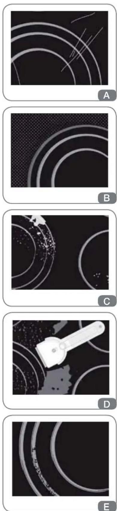
Ceramic glass hob should be cleaned only when completely cooled down, preferably after each use, otherwise even the slightest stains remaining after cooking may burn into the hob surface with each following use.
For regular maintenance of ceramic-glass hob use special cleansing agents, produced in such way to create protective film upon the surface.
Before each use, wipe the dust and other particles from the hob, they may scratch the surface (Fig. A).
Caution: use of steel wool, abrasive cleaning sponges, and abrasive detergents can scratch the surface of the hob. The surface may also be damaged by the use of aggressive sprays and inappropriate liquid chemicals (Fig. A and B).
Pattern marks can be erased by the use of aggressive agents or rough and damaged cookware bottoms (Fig. B).
Minor stains are removed with moist soft cloth; after that the surface should be wiped dry (Fig. C).
Water stains are removed with gentle vinegar solution, but you must not wipe the frame with it (certain models only), since it may lose its glow. Never use any aggressive sprays or limestone removers (Fig. C). Major stains are removed with special ceramic-glass cleansers.
Follow strictly the manufacturer's instructions.
Be careful to remove any remains of cleansing agent from the surface, otherwise they will be heated during the next use and can damage the hob (Fig. C).
Stubborn and burnt stains are removed with special ceram scraper. Be careful, however, not to touch the hotplate surface with the scraper handle (Fig. D).
Handle the scraper with utmost care to avoid injuries!
Sugar and sugar containing food may permanently damage the ceramic-glass hob surface (Fig. E), so the remains of sugar and sugar containing food must be scraped off from the hob surface immediately, when the hotplates are still hot (Fig. D).
Discoloring of ceramic-glass hob has no effect whatsoever on its operation and stability. In most cases, it appears as the consequence of burnt in food remains, or as a result of dragging pots and pans (especially aluminium or copper bottom cookware) across the surface, and such discoloring is rather hard to remove.
Note: All described faults are mostly esthetical and do not affect directly the operation of the appliance. Remedy of such fair covered by warranty.
DOWNDRAFT
USE
The product has been designed to extract fumes, grease and cooking steam. It has been designed to work in both suctioning mode, with outside evacuation, and filtering mode.
Outside - discharge version
The product can be installed with an external discharge outlet. In this case, install the extraction ducting to the outside of the building (extraction ducting not supplied).
Non-return valve blockage

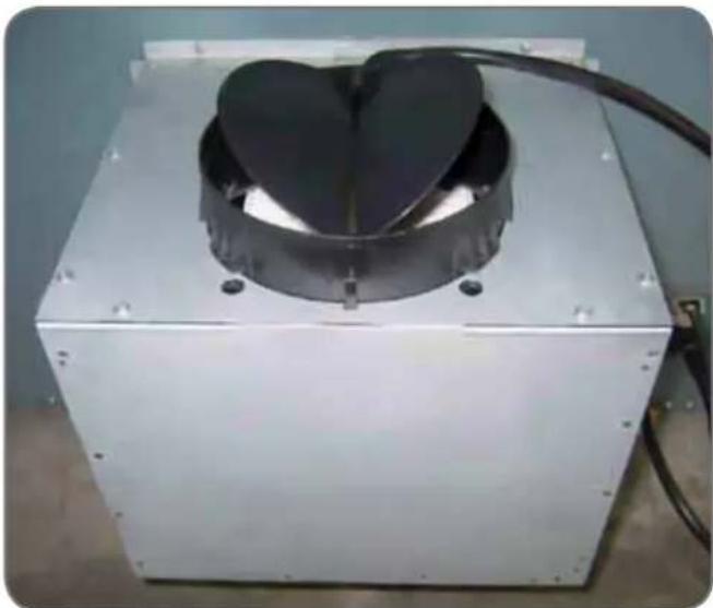
Before connecting the air exhaust hose, make sure that the non-return valves can rotate freely.
natural_image
Exterior view of a metallic industrial device with a heart-shaped top component (no text or symbols visible)In case of outside air discharge installation, fit a non-return valve to prevent wind and back air from entering.
Filtering mode
In case fumes and vapour cannot be evacuated outside, the appliance can be used in the filtering mode.
Activated charcoal filters are required for this type of cooker hood.
Air recycled through the charcoal filters is recirculated into the kitchen, thanks to a duct conveying the air on one side of the cabinet (Fig. 17).

Installation must comply with the regulations in force regarding the ventilation of enclosed environments. In particular, discharged air must not be conveyed into a duct used for fumes discharge or discharge from appliances using gas or other combustible materials. The use of discontinued ducts is not allowed without the approval of a qualified technician.
GREASE FILTER REMOVAL, MOUNTING THE ACTIVATED CHAR- COAL FILTER
The removal and fitting of the grease and carbon filters need to be carried out with the downdraft in the open position. To do this, select; ↑↓. then remove the front panel by simultaneously pulling on both sides of the upper part. The panel will rotate forwards to make it possible to access the grease filters (Fig. 15). Remove the grease filters to access the carbon filters (Fig. 16). The replacement of the charcoal filters has to be carried out accordingly to the effective use of the Downdraft, and in any case at least once every 6 months.

After having replaced the filters, reinstall the front stainless steel panel, otherwise the Downdraft is not enabled to function.
ELECTRICAL CONNECTION OF THE DOWNDRAFT
WARNING
Place the metal box containing the electronic components at a distance of no less than 65 cm from gas-operated cook tops or in any case, 65 cm from the suctioning surface of the cooker hood.
NOTE
We recommend installing the metal box containing the electronic components at least 10 cm above floor level and at a suitable distance from all heat sources (e.g. oven sides or cook top).
CAUTION
This appliance is fitted with an H05 VVF 3 conductor, 0.75 mm ^2 (neutral, phase, and ground) power cord.
This can be connected up to a 220 - 240 V mono-phase electrical network through a CEI 60083 approved power socket, which must remain accessible after installation, in compliance with installation regulations.
We decline any responsibility in case of accidents caused by a lack of ground connection or incorrect ground connection. The appliance must be fed through a differential protection device (RCD), with a nominal residual current not exceeding 30mA. If the power cord is damaged, call the after-sales service to avoid any risk.
Once the installation is completed it is necessary to give electricity supply to the Downdraft pressing the red button placed above the metallic box with the wiring boards inside.
WARNING
Connecting the product to the mains electricity must be carried out by technically qualified and specialised personnel.
The product must be connected to an electrical system correctly designed and installed.
The electrical system must comply with VDE0100 standard.
DANGER
If the product shows signs of a fault, disconnect the appliance or remove the fuse corresponding to the disconnection line of the appliance.
If the product is not provided with a plug or if the plug is not easily accessible, it will be necessary to install a thermomagnetic circuit breaker switch on the electricity line between the product and the electrical system to which it is connected to that has a contact aperture of the poles of at least 3mm.
ELECTRICAL CONNECTION

This appliance complies with the European Directives 2006/95/EC (Low Voltage Directive) and 2004/108/EC (Electromagnetic Compatibility).
While installing the appliance and carrying maintenance operation, make sure it is disconnected from the electrical network or the fuses are cut out or removed.
Check that:
• Power is enough.
- Feeder lines (mains) are in good tions.
- The cables diameter complies with installation regulations.
FUNCTIONS OF THE DOWNDRAFT
A: Light ON/OFF key
The light switches on and off only when the carriage is fully OPEN.
Pressing this button with the carriage closed will cause the carriage to open and then the light will switch on.
The button also serves to switch off the light if it is on.
condi-
B: ↑↓ ON/OFF key
This starts the extraction carriage upward movement and when it is fully open, it sets the second extraction speed.
With the carriage open: it switches off the motor and if on, the light; then it retracts the extraction carriage.
C: - (-) Key
This reduces the speed of the extractor motor from the 4th speed until the motor switches off, without closing the pull-out carriage.
D: □□□□ Indicators
- This signals the speed setting, by only the relevant LED switching on.
- This signals that all filters have been rated by all LEDs switching on.
E: + (+) Key
This increases the speed of the extractor motor, from 1st to 4th speed, without moving the extractor panel.
F: Timer
10 min after setting, it serves to stop the extractor motor, close the carriage and switch the lights off, if they are on.
The set function is signalled by the flashing LEDs "D" for the set speed.
The timer can be cancelled by pressing the key again.
Other functions:
Automatic turn off:
After 4 hours of continuous working from the last setup, the appliance turns off and closes automatically.
Grease filters saturation:
After 30 hours of working, the speed indicators "D" will all flash simultaneously, signaling the grease filters saturation.
To reset this alarm, hold down the button for at least 3 seconds, while the carriage is open.
Calibration:
The cooker-hood carries out its self-calibration every 3 complete cycles of its extractable unit.
By pushing the "TIMER" key 6 times consecutively (MAX break between one push and the other is 3 sec.) all the leds will flash and the calibration will be reset.
After the next 3 cycles the downdraft will carry out its self-calibration.
Stand-by:
When the extractable unit is closed and the light is switched off, the control panel, after 6 seconds, activates the Stand-by function, reducing the brightness of the leds.
This function can be stopped by pressing ON/OFF or LIGHT key.
Security system:
If there is an obstacle while the extractable unit is closing, the Downdraft stops closing and rises again thanks to a security system.

This operation has to be carried out by a specialized technician.
"TIMER"
CLEANING AND MAINTENANCE OF THE DOWNDRAFT
Careful maintenance ensures proper operation and good performances over time.

The hood must be disconnected from the electrical network, both by unplugging the appliance from the socket and activating the magnetic circuit breaker (safety cut-out), before removing the metal grease filters. After cleaning operations, replace the metal grease filters as outlined in the installation instructions.
| MAINTENANCE HOW TO PROCEED? | ACCESSORY PRODUCTS TO USE | |
| External surfaces and accessories | Do not use metallic scrubbers, abrasive products, or hard brushes. | To clean the external surfaces of the cooker hood and the light housing screen use only commercially available household detergents diluted in water. Then rinse with clean water and dry with a soft cloth. |
| Active charcoal filter with extractable unit open | After 30 hours of operation, the downdraft will signal the grease filter saturation.The saturation is signaled by the blinking of the 4 central leds.To reset, hold down the timer button for at least 3 seconds, while the carriage is open. | The grease filters can be washed by hand or in the dishwasher. These filters need to be cleaned on a regular basis, because otherwise they may represent a fire risk.Refit the grease filters and front panel, making sure that the panis properly fitted at the sides so that it it does not cause the downdraft to stop operating. |
| Active charcoal filter | In the recirculation mode, the active charcoal filter must be replaced periodically.To remove the charcoal filter first of all it is necessary to remove the grease filter and then pull the plastic key of the panel itself, in order to disengage it from its seating.Follow these steps in reverse order to insert the active charcoal filter.Replace the used charcoal filter on an average of every six months. | |
OPERATIONAL
ANOMALIES
| PROBLEM SOLUTION | |
| The product does not work... | Check that:There is not a power outage.A specific speed has actually been selected.The 9 pole connection is inserted properly.The red reset key, found over the electrical system box, is pushed.Make sure that the wires of the 9 pole connection are inserted properly in the connector itself (during the connection phase, an excessive pressure could bend the contacts). |
| The product is not functioning at the maximum... | Check that:The motor speed selected is sufficient for the quantity of fumes and vapours present in the room.The kitchen is ventilated well enough to allow air for intake.The charcoal filter is not worn out.(filtering version cooker hood).The air outlet channel is free and compliant.The non-return valves of the suctioning unit are free to rotate. |
| The product stops whilst functioning | Check that:There is not a power outage.The omnipolar device has not tripped. |
AFTER SALES
SERVICE
Any maintenance operation on your appliance should be carried out by:
• Either your retailer;
• Or another qualified professional technician, authorized for that brand.

NOTE

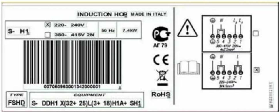
When calling, please mention the appliance details (Type and equipment and production date). This information is mentioned on the rating label and the production date one placed on the lower side of the downdraft.
IMMAGINI IMAGES
natural_image
3D rendering of a metallic panel or bracket with red rectangular components and mounting holes (no text or symbols visible)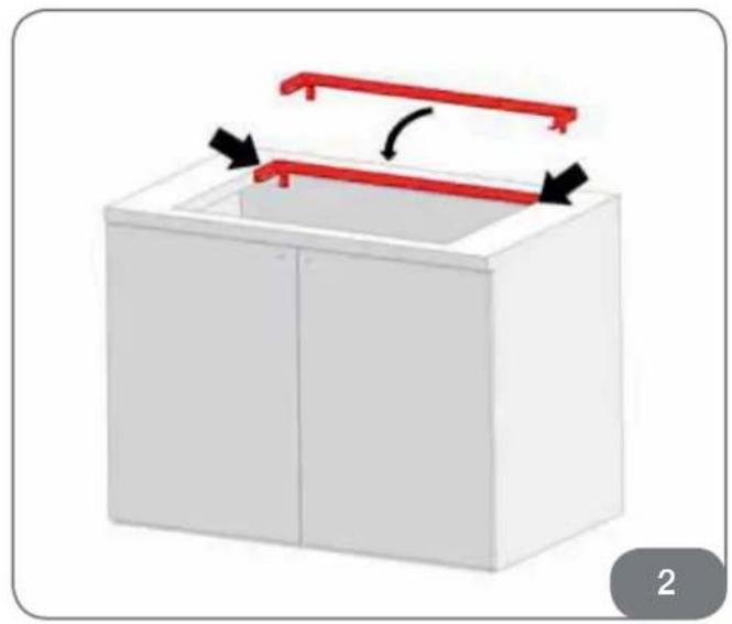
natural_image
3D diagram of a white cabinet with red horizontal bars and black arrows indicating rotation or movement (no text or symbols)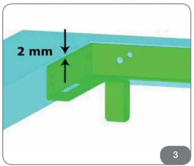
natural_image
3D mechanical assembly diagram showing green and red components with mounting brackets (no text or symbols)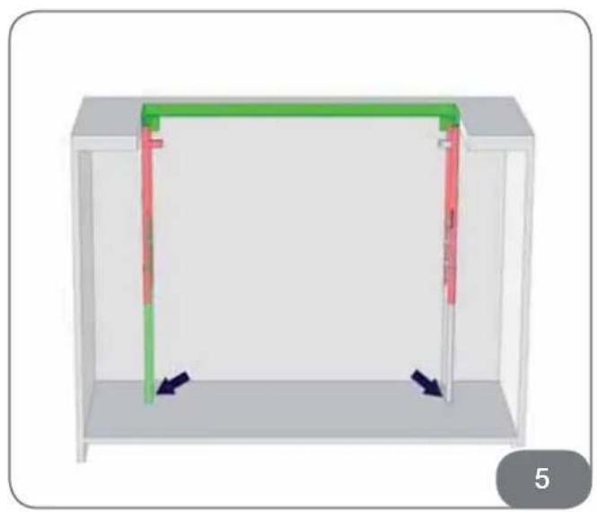
natural_image
3D diagram of a rectangular enclosure with green and red vertical bars, showing internal structure and directional arrows (no text or symbols)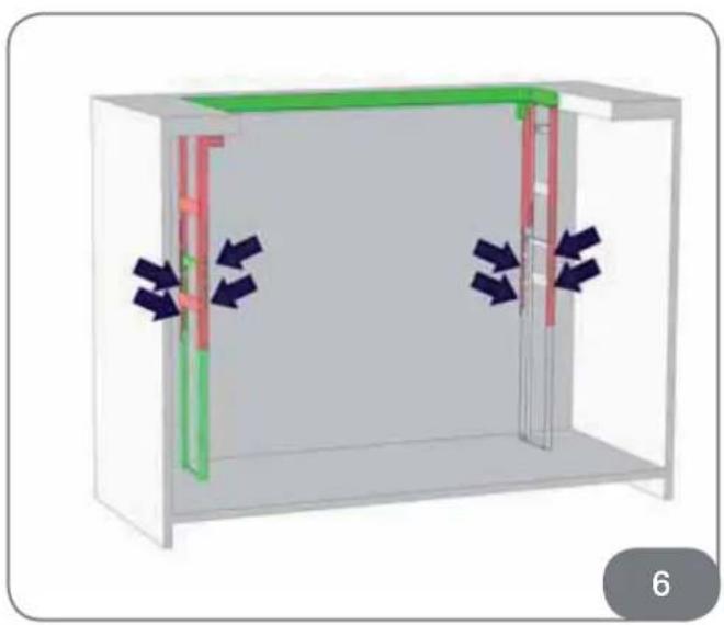
natural_image
3D diagram of a room with internal pipes and ventilation ducts, showing directional arrows (no text or symbols)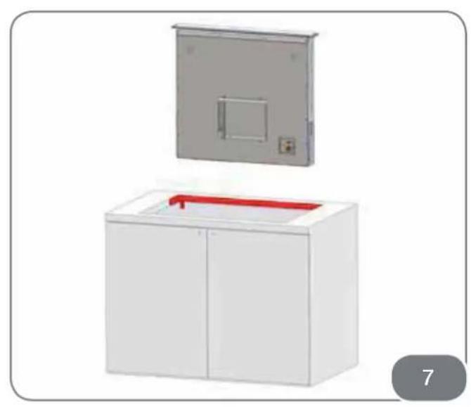
natural_image
Illustration of a white cabinet with a red handle and a gray panel on top (no text or symbols)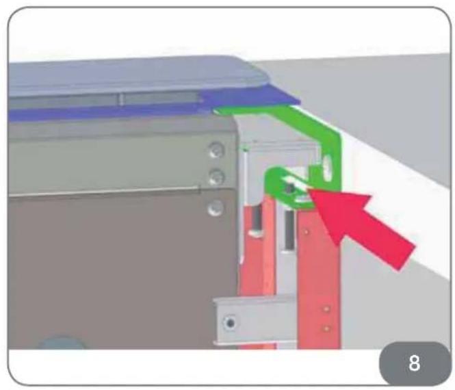
natural_image
3D mechanical assembly diagram showing a component with colored parts and a red arrow indicating direction (no text or symbols)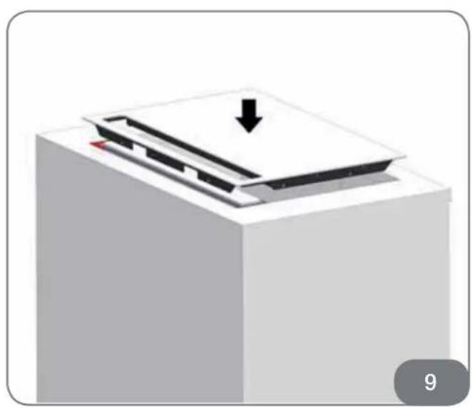
natural_image
3D diagram of a printer or printer with a downward arrow pointing to the cover (no text or symbols present)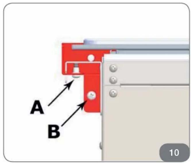
natural_image
Interior view of a room with a door, control panel, and directional arrows indicating movement (no text or symbols)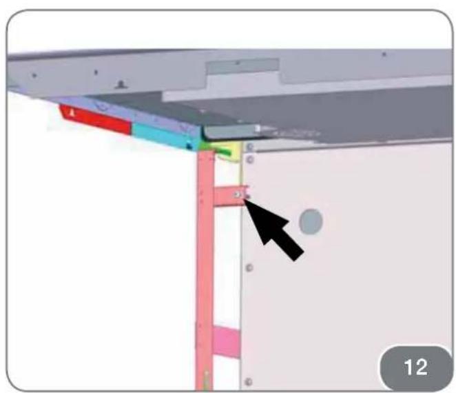
natural_image
3D diagram of a mechanical assembly with colored components and a black arrow pointing to a detail (no text or symbols)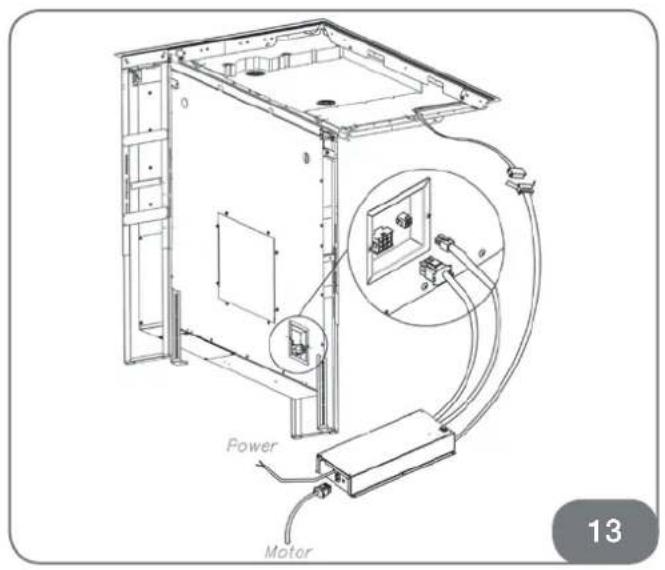
natural_image
3D diagram of a mechanical assembly with two red components and directional arrows indicating movement or force (no text or symbols)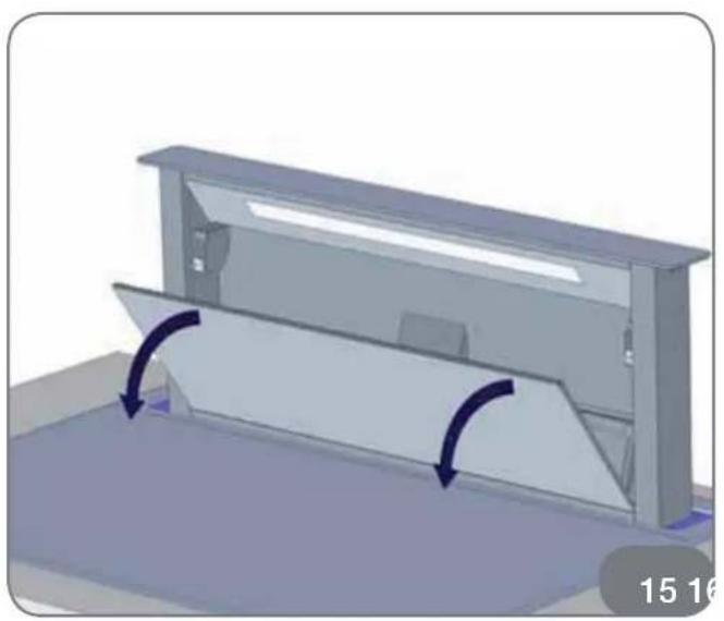
natural_image
3D diagram of a mechanical device with directional arrows indicating motion or force, no text or symbols present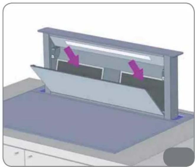
natural_image
3D diagram of a device with two purple arrows pointing to internal components, no text or symbols present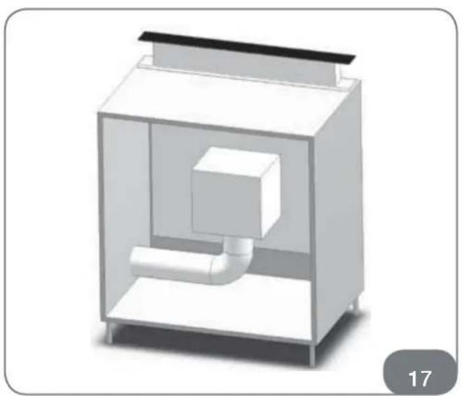
natural_image
3D rendering of a simple indoor air purifier or vent with a central pipe and top cover (no text or symbols)90002020019 - C - 09/2014
- GENTILE CLIENTE
- NOTA
- INSTRUCTION FOR USE
- INSTALLATION INSTRUCTION
- FIRE HAZARD PROTECTION
- CONTENTS
- COOKING HOB
- DOWNDRAFT
- IMPORTANT WARNINGS ABOUT THE COOKING HOB
- IMPORTANT WARNINGS ABOUT THE DOWNDRAFT
- In the case of the version with external motor, for normal downdraft operation, it is necessary to use a suctioning unit (external motor) made by the same manufacturer.
- TECHNICAL
- DRAWING
- INSTALLATION OF THE COOKING HOB WITH INTEGRATED DOWNDRAFT
- CAUTION!
- BUILT-IN INDUCTION HOB OPENING DIMENSIONS
- that INSTALLING THE FOAM GASKET
- INSTALLATION PROCEDURE
- CONNECTION TO THE POWER SUPPLY
- BASIC ADJUSTMENT OF SENSORS TO THE AMBIENCE
- WARNING
- INSTALLATION DIAGRAM:
- TECHNICAL INFORMATION
- HOTPLATE FUNCTION PRINCIPLE
- APPROPRIATE COOKWARE FOR INDUCTION HOTPLATES
- Dish recognition
- Hotplate may be damaged if:
- POWER REGULATION
- ENERGY SAVING TIPS
- CERAMIC-GLASS
- COOKTOP
- HOB CONTROL ELEMENTS
- SLIDE CONTROL POWER
- HOB CONTROL
- ACTIVATING THE HOB
- NOTE
- TURNING HOTPLATES ON
- Changing hotplate power settings
- SWITCHING HOTPLATES OFF
- SWITCHING THE HOB OFF
- LOCKING THE CONTROL UNIT
- Activating the control unit lock
- Deactivating the control unit lock
- PAUSE FUNCTION
- Activating the Pause function
- While the Pause function is active:
- Deactivating the pause mode:
- RECALL FUNCTION
- REMAINING HEAT INDICATOR
- EXTRA POWERFUL SETTING
- (HOTPLATES MARKED "P")
- Activating extra powerful setting
- Premature turning extra powerful setting off
- HEAT UP TIME AUTOMATIC
- Activating Bridge Function
- Deactivating Bridge Function
- WARMING FUNCTION
- Activating heating function:
- SAFETY SWITCH OFF
- PROTECTION FROM OVERHEATING
- TIMER
- Turning timer on
- Changing preset cooking time
- Checking remaining cooking time
- Turning timer off
- If you want to switch off the timer prior the end of preset time:
- ALARM TIMER FUNCTION
- Timer setting
- Switching the alarm off
- SAFETY FUNCTIONS AND ERROR SIGNALS
- CLEANING AND MAINTENANCE OF CERAMIC-GLASS HOB
- USE
- Outside - discharge version
- Non-return valve blockage
- Filtering mode
- GREASE FILTER REMOVAL, MOUNTING THE ACTIVATED CHAR- COAL FILTER
- ELECTRICAL CONNECTION OF THE DOWNDRAFT
- CAUTION
- DANGER
- ELECTRICAL CONNECTION
- FUNCTIONS OF THE DOWNDRAFT
- A: Light ON/OFF key
- B: ↑↓ ON/OFF key
- C: - (-) Key
- D: □□□□ Indicators
- E: + (+) Key
- F: Timer
- Other functions:
- Automatic turn off:
- Grease filters saturation:
- Calibration:
- Stand-by:
- Security system:
- CLEANING AND MAINTENANCE OF THE DOWNDRAFT
- OPERATIONAL
- ANOMALIES
- AFTER SALES
- SERVICE
- IMMAGINI IMAGES
Brand : SIRIUS
Model : SDDH-11P
Category : Cooker