Serie Tilla CH 1259 IXC N - Cooker Respekta - Free user manual and instructions
Find the device manual for free Serie Tilla CH 1259 IXC N Respekta in PDF.


| Product Type | Standard Cooker Hood (Extractor Hood) |
| Brand | Respekta |
| Model | Serie Tilla CH 1259 IXC N |
| Power Supply | 220-240 V, 50 Hz (see rating plate) |
| Fan Speeds | 3 speeds: Low, Medium, High |
| Lighting | LED bulb, E14 base, 15 LUX/W |
| Modes | Exhaust air (factory) and recirculation (requires carbon filter) |
| Grease Filter | Aluminium mesh, washable (hand or dishwasher at 60°C) |
| Carbon Filter | Optional, not included (washable/regeneratable type recommended) |
| Minimum Distance (Electric Hob) | 65 cm |
| Minimum Distance (Gas Hob) | 70 cm |
| Exhaust Air Diameter | Minimum 120 mm |
| Control Panel | Mechanical buttons (Light ON/OFF, Motor ON/OFF, Speed selection) |
| Material | Stainless steel (housing), glass (steam screen) |
| Safety Features | Automatic shutdown? (not specified); fire risk if filters not cleaned; must not discharge into flue used for other appliances |
| Warranty | 24 months from purchase date (subject to conditions) |
Frequently Asked Questions - Serie Tilla CH 1259 IXC N Respekta
User questions about Serie Tilla CH 1259 IXC N Respekta
0 question about this device. Answer the ones you know or ask your own.
Ask a new question about this device
Download the instructions for your Cooker in PDF format for free! Find your manual Serie Tilla CH 1259 IXC N - Respekta and take your electronic device back in hand. On this page are published all the documents necessary for the use of your device. Serie Tilla CH 1259 IXC N by Respekta.
USER MANUAL Serie Tilla CH 1259 IXC N Respekta
Operating & Installation Instructions
Cooker hoods
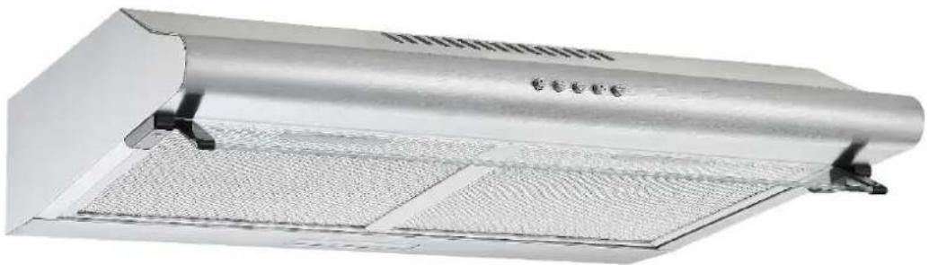
natural_image
Exterior view of a stainless steel kitchen fan with ventilation grilles (no text or symbols visible)Respekta
Modell
CH 1295 IXC N
WH10A-DD8-CL
Lieber Kunde,
9. Störung- was tun wenn...
mit
natural_image
Two technical line drawings showing a device with a circular component and a hand inserting a button (no text or symbols)15. GERÄTEBEDIENUNG
STANDARD ABZUGSHAUBE
Respekta
CH 1259 IXC N
natural_image
Technical line drawing of a mechanical component with labeled parts (C and V), no readable text or symbols beyond labelsnatural_image
Technical line drawing of a device with a circular component and a knob, no text or symbols present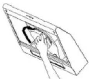
natural_image
Line drawing of a hand inserting a device into a device panel (no text or symbols)- Problembehandlung
natural_image
Line drawing of a kitchen appliance with a downward arrow indicating a component (no text or symbols present)natural_image
Line drawing of a kitchen air conditioner unit with ventilation slots and internal components (no text or symbols)natural_image
Diagram of a ceiling-mounted air vent with ventilation grilles and a labeled component '3a' (no text or symbols beyond label)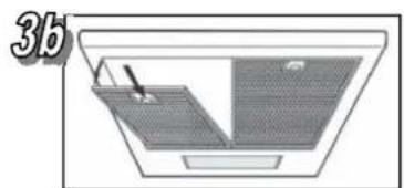
natural_image
Diagram of a roof structure with slanted roof and ventilation grilles (no text or symbols)2. Wandmontage
natural_image
3D diagram of a rectangular container with two curved arrows indicating flow or movement, no text or symbols present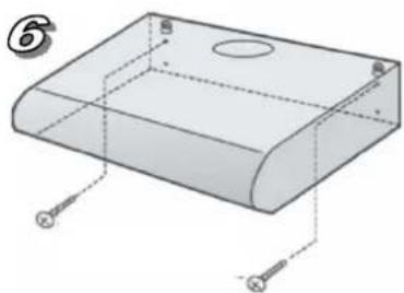
natural_image
3D diagram of a rectangular electronic component with mounting holes and wiring (no text or symbols)natural_image
Pure mechanical assembly diagram showing a bracket with circular holes and an arrow indicating force (no text or symbols)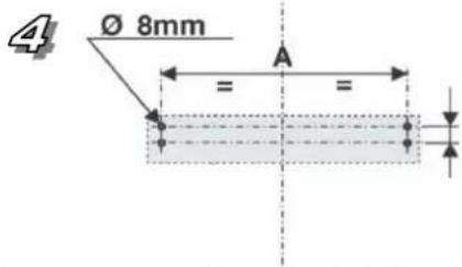
natural_image
Diagram of a computer monitor with an open screen showing a spherical object, no text or symbols presentGarantiebedingungen
The manufacturer does not take any responsibility for damage caused by the buyer.
This device has been manufactured and tested according to the latest methods.
Irrespective of the seller's / dealer's statutory warranty obligation, the manufacturer provides a 6-month warranty for faultless material and faultless production for a period of 24 months from the date of purchase. The warranty expires in case of intervention by the buyer or by third parties.
Damage caused by improper handling or operation, by incorrect installation or storage, by improper connection, improper installation, as well as by force majeure or other external influences, is not covered by the warranty.
We reserve the right to repair or replace defective parts or to exchange the device in case of complaints.
Only if repair (s) or replacement of the device, the intended use by the manufacturer should not be finally achieved, the buyer can demand warranty within six months, calculated from the date of purchase, reduction of the purchase price or cancellation of the purchase contract.
Claims for damages, including consequential damages, unless they are based on intent or gross negligence excluded.
The warranty claim has to be proven by the buyer, by presenting the purchase receipt. The warranty is valid within the Federal Republic of Germany.
Standard Cooker hoods
Chapter p age

- Explanation of information symbols----2
Warning 2 - Intended use 3
- Protection of the environment 3
- Tips and general advice ----3
- Before using the hood ----3
- Using the hood / Safety information----3
- Cleaning and care 4
- Changing the lamps----5
- Faults – what to do if ... 5
- Customer service----5
- Installation----6
- Exhaust air pipeline----7
- Guaranty 7
- Appliance components 8
- Appliance operating (key and switch functions)----9
- Problem shooting 10
- How to change the lamp---- 11
- General installation instructions ---- 12
Warranty Conditions: See last page.

We recommend that you read these operating instructions carefully.
This will enable you to become better and more quickly familiar with your new appliance. Mark those parts, which are of special importance to you. Keep this document to hand, so that you can refer to it at any time and pass it on to any subsequent owners. Certain details in these instructions may differ on your device. For commercial use, the guarantee and warranty are reduced by 50%
You have chosen a good appliance, which will give you many years of excellent service if properly operated and maintained.

Our appliances are not intended for commercial usage. They are designed only for domestic use.
The warranty and its provisions are reduced by 50% in the case of commercial usage.
1. Explanation of information symbols
This symbol on the product or its packaging indicates that this product is not to be treated as normal domestic waste but must be disposed of through a special collection depot for recycling electrical and electronic equipment.
Through your contribution to the correct disposal of this product you are protecting the environment and the health and welfare of your fellows.
Incorrect disposal endangers the environment and your health. You can obtain more information on the recycling of this product from your local council authorities, your waste disposers or the sales outlet from which you purchased the product.
The following symbol has the following significance:

This is a safety information symbol.
This is to be found in particular with all descriptions of actions where there is a possibility of danger for persons.
Pay attention to this safety information and behave with appropriate care.
Pass these warnings on to other users.
GB
Dear customer,
Thank you for your confidence and for purchasing a device from our range.
The device you have purchased is designed to meet its requirements.
Please read these operating instructions carefully. They describe the features and functions of your device.
These operating instructions can be adapted to several device types. You will therefore find descriptions of functions which may not be relevant for your device.
The manufacturer does not accept any responsibility for damage to persons or property resulting from defective or inappropriate installation of the device.
The manufacturer reserves the right to make any necessary model changes to device types, to improve user-friendliness and to protect the user and the device and which comply with current technical standards.
Despite our ongoing quality control, should you wish to make a complaint, please contact Customer Service. They will be pleased to assist.
Declaration of conformity CE
The manufacturer of the product(s) described herein, hereby declares that it/they comply with the relevant, fundamental safety, health and security requirements of applicable EC directives and shall provide the corresponding test reports, in particular the declaration of conformity CE issued by the manufacturer or its agent if requested to do so by the authorities and which may be requested by the device vendor.

This is a warning symbol
This is to be found with descriptions of actions where special care is necessary to prevent damage to appliances. Pass this safety information on to all users of the appliances.

This symbol refers to useful hints and tips and draws your attention to the correct procedure andaviour. Compliance with the information marked with this symbol will spare you many problems.

Warning
- There is a fire risk if cleaning is not carried out in accordance with the instructions.
- The air must not be discharged into a flue that is used for exhausting fumes from appliances burning gas or other fuels (not applicable to appliances that only discharge the air back into the room)
• Regulations concerning the discharge of air have to be fulfilled. - When the range hood and appliances supplied with energy other than electricity are simultaneously in operation, the negative pressure in the room must not exceed 4 Pa (4 x 10⁻⁵ bar).
- Cooker hoods are not intended for use by persons (including children) with reduced physical, sensory or mental capabilities, or lack of experience and knowledge, unless they have been given supervision or instruction concerning use of the appliance by a person responsible for their safety.
• Children should be supervised to ensure that they do not play with the appliance.
- Keep your children from using the cooker hood.
- Your cooker hood is for domestic use only, not suitable for barbecue, roast shop and other commercial use.
- If the supply cord is damaged, it must be replaced by the manufacturer, its service agent or similarly qualified persons in order to avoid a hazard.
- There shall be adequate ventilation of the room when the range hood is used at the same time as appliances burning gas or other fuels (not applicable to appliances that only discharge the air back into the room);
- Any installation work must be carried out by a qualified electrician or competent person.
- The cooker hood and its filter mesh should be cleaned regularly in order to keep in good working order.
- Before cleaning, always ensure that you have switched your cooker hood off.
- Clean the cooker hood according to the instruction manual and keep the cooker hood from the danger of burning.
- Do not flame under the range hood;
- If there is any fault with your cooker hood, please call the service department appointed by agent for servicing.
- Please keep the room draughty when your cooker hood and gas hob are working.
- Do not exhaust the gas from cooker hood through the same heated flue which is for the gas from gas hob and other kitchen appliances.
- Before installation and usage, read all the instructions and make sure that the voltage (V) and the frequency (Hz) indicated on your cooker hood are exactly the same as the voltage (V) and the frequency (Hz) in your home.
- In order to get the most out of your cooker hood, please read the instruction manual before installing and using, and keep it in a safe place.
- Ensure that you could get our guarantee for your cooker hood, please provide the warranty card and purchase receipt, or the guarantee will not be offered.
CAUTION: Accessible parts may become hot when used with cooking appliances.
2. Intended use

The appliance is intended for domestic use.
The manufacturer is not responsible for damage resulting from improper use or maloperation.

Extractor hoods remove unpleasant odours and ours and create a pleasant room atmosphere.
Particles of grease, steam and also moisture are absorbed by the grease filter.
A correctly dimensioned extractor hood creates a pleasant room climate without producing draughts and ensures a bearable air humidity of 40-60%.

Make sure no open fire is burning in the fireplace before you switch on the appliance or there may be a heavy smoke formation in your home.
Toxic combustion gases can also be drawn from the chimney or flue, into living rooms. This can be lethally dangerous!
3. Protection of the environment
3.1 Packing
The packing materials are 100% recyclable. Comply with local regulations for their disposal.

The packing materials (plastic bags,
polystyrene moulded parts etc) are dangerous for children. So keep packing material out of the reach of children.
3.2 Disposal

If this appliance is a replacement for an old appliance, please dispose of your old appliance according to the statutory regulations. Prior to disposal the appliance must be rendered unserviceable by cutting off the power supply cable. The appliance is to be sent for disposal to the responsible collection authorities.
4. Tips and general advice


a) Prior to carrying out cleaning or maintenance work the power supply to the extractor hood is to be cut off by removing the supply plug.
b) The air extracted from the hood is not to be routed over the exhaust air pipeline of the heater or other non-electric operated appliances.
c) No flambé dishes are to be prepared under the extractor hood. The open flames could destroy the hood or even cause a kitchen fire.
d) Never leave pans unwatched when frying because fat can easily catch fire.
e) Constant maintenance guarantees problem-free operation and optimal hood performance.
f) If the hood is used together with other non-electrically operated appliances, the room partial vacuum must not exceed 4 Pa (4 x 10⁻⁵ bar).
g) Make sure that the room is adequately ventilated.
h) Regularly clean encrusted food from appliance surfaces.
i) Regularly clean or replace the filter.

The exhaust air hose must not be made from or contain flammable materials.
5. Before using the hood
- Ensure that the hood has not suffered damage during transport.

Installation and connection of the electrical supply and the exhaust air must be carried out by experienced tradesmen according to the manufacturer's instructions and in compliance with the local requirements.
6. Using the hood
6.1 Operating safety information

The grease filter must always be in place when operating the hood, otherwise grease vapour can become deposited in the hood and the exhaust air system.
- With gas hobs, take care that hobs are not operated without cooking utensils.
Parts of the hood can be damaged by the rising heat from open gas flames.
- Flame cooking under the hood is not permitted due to the fire risk. The rising flame can set fire to grease deposited in the filter.
- Due to the fire risk, frying or cooking with oils and fats under the hood is only to take place under constant surveillance.
Attention! The risk of self-ignition increases with oils which have been used repeatedly used.
- Other activities with an open flame are not permitted. These could damage the filter or other parts of the appliance or even start a fire.
6.2 In exhaust air mode:
The extracted air is emitted outdoors via the exhaust hose.
For this purpose your house must have an exhaust air shaft or an exhaust air pipeline leading outdoors.

When using the hood in exhaust air mode
and operating with chimney-dependent firing methods, (e.g. coal oven) care must be taken for an adequate supply of fresh air in the installation location. Always discuss this with your responsible chimney-sweeping specialist.
If no permanently installed exhaust air pipeline or exhaust air shaft is available, you must operate the hood in circulation air mode. (see chapter 11.3)
6.3 In circulation air mode:
The inlet air is filtered through a carbon filter (also known as active carbon filter) and circulated in the room. The carbon filter captures the odours produced through cooking.
The filtered air is circulated back into the kitchen through air openings at the side or on the top. If the hood is used in circulation air mode, it is absolutely safe to simultaneously operate a room air-dependent fire.

Switch on the appliance a few minutes prior to announcing cooking.
It is recommended with both exhaust and circulation air modes to run the fan a further ca. 5 to 10 minutes after cooking. This will free the kitchen air of any remaining steam and odours.
- For improved hood performance, pull out the steam collector (where fitted).
- Set the fan speed according to the amount of smoke and odours to be extracted.
- Operate the hood for another ca. 5 to 10 minutes after finishing cooking.
- Refit the steam collector (where fitted).
After-run function
If your appliance is fitted with an after-run function, this can be activated by an additional key on the control panel (chapter 14).
7. Cleaning and care

Prior to any maintenance or cleaning work, isolate the hood from the electrical supply by: pulling out the appliance connector plug or
tripping the house installation circuit breaker or
fully unscrew the screw type fuse from the installation
- The extractor hood is not to be cleaned with a steam cleaner.
-
Do not use cleaning agents containing alcohol to clean appliances with a matt black finish. These can lead to discolouring.
-
Non-compliance with the maintenance and cleaning instructions can result in a fire hazard due to grease deposits.
- The grease filters on your appliance are to be cleaned or replaced at regular intervals. Filters saturated with grease can quickly catch fire and also distribute unpleasant odours.
- Grease filters obstructed by dirt particles seriously impair the appliance function.
- When cleaning the area of the control elements, take great care to prevent water entering the electronics.

Special information for appliances with tainless steel casing
A commercially available non-abrasive stainless steel cleaning agent should be used for cleaning stainless steel surfaces.
Treatment with a stainless steel preservative is recommended to prevent surfaces becoming quickly re-soiled. Apply the agent all over and economically using a soft cloth.

Never use stainless steel cleaning agents in nity of the control elements.

When cleaning metal grease filters take care damage the mesh. Frequent cleaning or the aggressive cleaning agents can cause colours to the metal surface. These do not affect your function and are not grounds for a paint.
7.1 Changing the grease filter
Grease filters must occasionally be changed. The following rules apply:
- Change paper grease filters monthly
- Change paper grease filters with alarm every two months or when the colour of the surface becomes visible through the mesh openings. This filter is coloured on one side; after fitting, this colouring must not be visible through the mesh openings.
- Foam grease filters must be soaked once a month in warm soapy water for 1 to 2 hours. Do not wring out; repeat where required and replace the filter by a new item after a maximum of 5-6 washes.
- Metal grease filters do not have to be replaced when they are over-saturated but washed once a month by hand or in a dishwasher (60°) (please do not use a corrosive rinsing agent). Allow the filter to
dry thoroughly and carefully replace it in the extractor hood.

Avoid using alkaline dishwasher cleaning agents (ph value over 7).
- Carbon filters
a) Traditional carbon filters (normally round in shape) can be neither washer nor regenerated.
The charcoal filters have to be replaced regularly, at least every 3 months or earlier, depending on the cooking habits
b) Washable and regeneratable carbon filters (normally square in shape) are to be washed once a month in a dishwasher, using a standard rinsing agent and with the intensive rinsing program (at the highest temperature).
Washable and regeneratable carbon filters absorb kitchen odours for a maximum of 3 years when cleaned monthly. The filter should then be replaced by a new item.

Washable and regeneratable carbon filters should be washed separately to avoid food residue deposits which can later cause unpleasant odours. After washing, the washable and regeneratable carbon filter must be reactivated. This is carried out by drying the cleaned filter in an oven for 10 minutes at 100^ C.
Read the package to see whether your carbon filter is washable and regeneratable.
If the package carries no information, then it contains a traditional, non-washable carbon filter.

Each time you change or wash a grease filter or soon filter, after removal clean all exposed lower parts of the hood with a mild grease solvent.
For the daily cleaning of the outer pats of the hood use a soft cloth moistened with alcohol or a mild liquid cleaner. Never use an abrasive cleaner.

There is a risk of fire if the instructions for the hood and the changing or cleaning of others are not complied with.
8. Changing the lamps

When changing a lamp, make sure that the new lamp does not have a higher wattage than that of the original.
8.1 Changing LED lamp
If the documentation of the cooker hood does not include an instruction for replacing lamps, the lamp must be replaced by the customer service for safety fi200812
reasons.
See also chapter "Customer Service"
9. Fault – what to do if ...
The motor fails to function:
• Is the plug properly inserted in the socket?
• Is there a power supply failure?
- Has a fuse blown?
The hood capacity is insufficient / operating noise has increased:
• Is the size of the exhaust air pipeline sufficient?
• Is the exhaust air duct blocked?
- The cross section of the air pipeline (from the hood to the wall box incl.) should be 120 mm.
- A smaller air pipeline cross-section can possibly impair the motor power.
- The air flow can be obstructed if the wall box is fitted with a fly mesh.
If this is the case remove the fly mesh.
- If the cover plate of the wall box has fixed, very inclined louvres, you should remove the plate to check whether this solves the problem.
- Mount a cover plate with movable louvres in the wall box, as this will least obstruct the air flow.
• Is / are the filter(s) clean? - Was / were the carbon filter(s) installed more than six months ago?
Then this/these should be changed.
- Is the air taken from the kitchen being replaced by sufficient fresh air, so that no partial vacuum is being produced in the room?
The lighting fails to function:
- Does the lamp need changing?
- Has the lamp been properly fitted and seated in the holder up to the stop?
- Is the fuse blown or has the circuit breaker tripped out?

If all the above checks fail to remedy the fault, ssible you have a more serious problem.
In no circumstances try to repair the electronic/electrical components in the appliance.
Contact your Customer Service.
10. Customer Service
For technical queries concerning your appliance please contact the customer service office of your dealer.
Before calling the customer service please note Model/Type of your appliance.
The type and rating plate is located inside the appliance (remove the grease filter)
11. Installation

Before installation of the appliance please pay regard to:
• Installation of the appliance only at a convenient place
- Check the wall / ceiling on sustainability and resilience
- Check the routing of electrical and other conductions in and on the wall respectively ceiling, in order to not damage them with the drill
- Check the condition and resilience of electric conduction
- We recommend the installation of the appliance by a professional
On installation, the minimum distance between the hob and the hood must be exactly complied with (see chapter 11.1 "Installation data") and follow the numbering of the steps and the additional instructions. Execution with air exhausted outdoors (A- see also the installation data). The vapours are extracted via an air exhaust hose fixed to the connector ring.
The diameter of the exhaust air hose must conform to that of the connector ring. If a smoke non-return valve is used or is planned, check whether it can open and close freely after the installation of the exhaust air hose. The extractor hood can be equipped with one (top) or two (top and back) extractor openings.
The hood is normally initially fitted out for use of the top extractor opening, as an extractor hood.
Openings not required are fitted with a plastic cover. This plastic cover can be easily removed by turning counterclockwise and optionally fitted to another opening which is not required.
11.1 Installation data
Minimum distance from the lower edge of the hood body:
to ceramic and cast cooking hobs 65 cm
to gas hob 70 cm
to hobs with coal/oil/wood firing 85 cm.

Only connect the appliance to the power
supply once it is properly installed.
11.2 Using the extractor hood as an exhaust air hood (with air extracted to outdoors)
If the extractor hood has been fitted at the factory with a carbon filter, this must be removed.
It is only practicable to use this when operating your hood in circulation mode.
11.3 Converting the extractor hood to a circulation hood
If you wish to use an appropriately fitted hood as a circulation hood, you must mount the active carbon filter(s) to the fan motor before using the hood.
The active carbon filter(s) is/are included in the scope of supply with some models.
Otherwise you must obtain the active carbon filter(s) from the supplier of your extractor hood.
You must also change your hood over to the "Filter position" at the device provided (lever or ball handle) inside of the hood.
11.4. Electrical connection

Before connecting the extractor hood, check the voltage stated on the rating plate (V) agrees the supply voltage in your home.

Never install the appliance if the data on the plate does not agree with your supply voltage.
You will find the rating plate inside the appliance, behind the grease filter.
If the extractor hood is fitted with a standard connector plug, connect this to an easily accessible standard socket.
11.5 Mounting the carbon filter
You will find the mounting instructions for the carbon filter in CHAPTER 15.
11.6 Mounting the extractor hood
See chapter "General installation instructions" or where applicable the separately supplied mounting instructions.
12. Exhaust air pipeline
(The exhaust air hose is not included in the scope of supply)
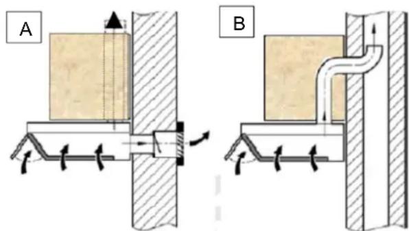
Fig. A air outlet to outdoors
Fig. B air outlet via an air shaft
English
Operating- and Installation Instruction Cooker Hood
- The exhaust air line should be as short and straight as possible.
- To avoid excessive noise or a reduced extraction capacity the diameter of the exhaust air pipeline should not be less than 120 mm.
- Use or form only large radius bends. Small radius bends reduce the extraction capacity of the hood.
- Use only smooth pipelines or flexible hoses of non-flammable materials for the exhaust air pipeline
- If the exhaust air pipeline is horizontally routed, there must be a minimum gradient of 1 cm per metre or an inclination angle of 2^ . (Fig. C)
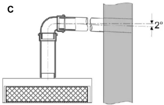
Otherwise condensation water could run into the extractor hood motor.
- If the exhaust air is directed into an exhaust air duct, the end of the entry fitting must be directed in the direction of flow.
- If the exhaust air pipeline is routed though cool rooms, lofts etc. there can be a large temperature drop within the individual parts of the pipeline, resulting in sweating or condensation water production. This renders outlet pipeline insulation necessary.
- In some cases a condensation water barrier must be installed in addition to adequate insulation. (these are available from leading building material suppliers).
13. Warranty
Please take note of the general guarantee terms and the guarantee period, stated in the attached guarantee card. If the appliance documentation does not include a guarantee card, please contact your dealer.
There is no Guarantee on light fittings.

The manufacturer is not responsible for any faults occurring through non-compliance with the above information and provisions.
The manufacturer is constantly engaged in the further improvement of his products. Please note that products are subject to changes in form, equipment and the applied technology.
fi200812
14. COMPONENTS OF STANDARD COOKER HOODS
EXHAUS AIR MODE (Factory setting)
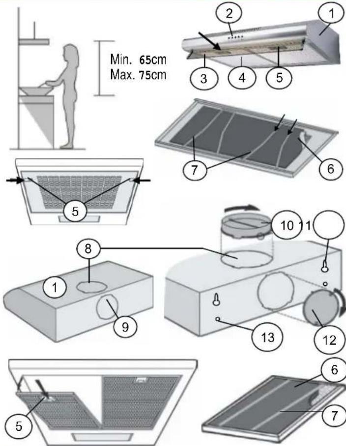
1 Hood body
2 Control panel
3 Glass steam screen
pivotally
4 Aluminium Grease filter
5 Filter fixing bolt
to open, push in direction of arrow
6 Filter mat*
7 Filter mat fixing bracket* to remove, press ends of brackets down and remove them from the anchorage
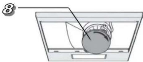
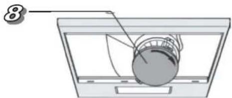
8 Upper exhaust air opening
9 Rear exhaust air opening*
10 Upper exhaust air cover
11 Hood suspension eyelets
12 Rear exhaust air cover*
13 Holes for locking screws
Change positioning flange (10) and blind cover 12) where necessary
* depending on Model
CHANGEOVER TO CIRCULATION AIR MODE
Carbon filter required. (not included in delivery)
To switch to recirculation mode, remove the mode selection block.
To do this, first disconnect the hood from the power supply and remove the aluminum grease filters (4).
Then mount the carbon filter by guiding it to the filter holder at the bottom of the motor and tightening it by turning it clockwise. (Bayonet lock)
Drawings/Pictures are for illustration purposes only
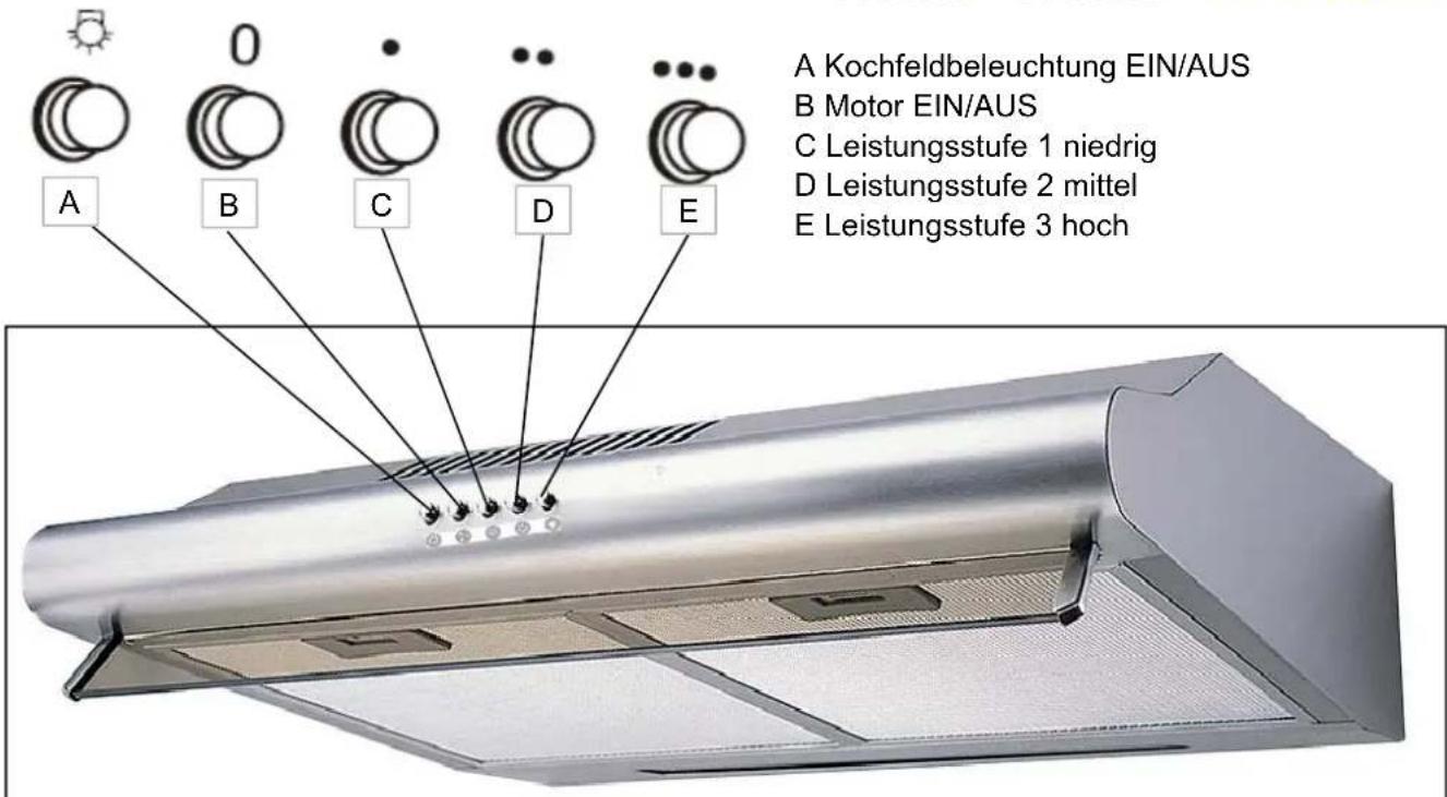
15. APPLIANCE OPERATING
STANDARD COOKER HOOD
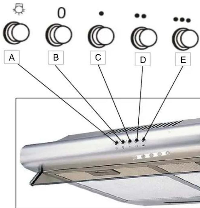
Respekta
CH 1259 IXC N
A Light ON/OFF
B Motor ON/OFF
C Speed level 1 LOW
D Speed level 2 MIIDLE
E Speed level 3 HIGH
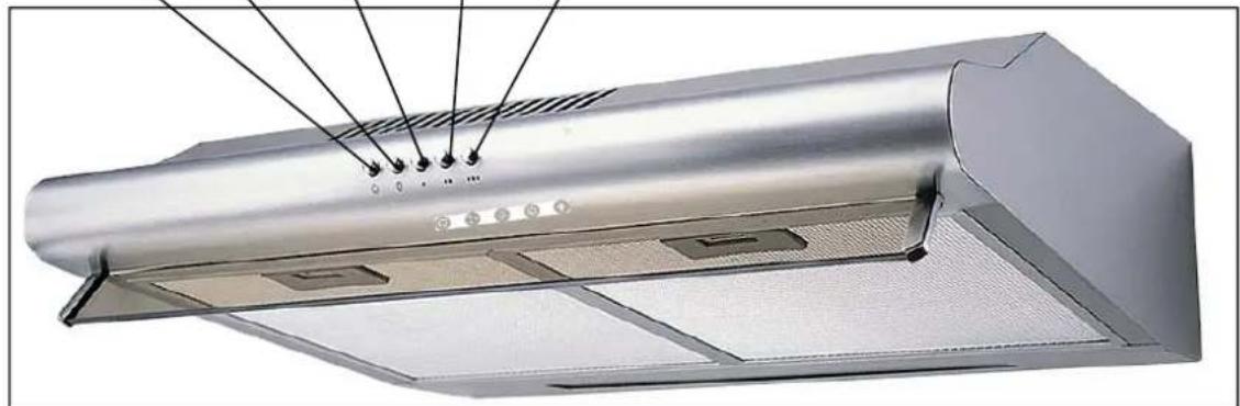
natural_image
Exterior view of a stainless steel kitchen air conditioner cover (no text or symbols visible)Recirculation mode
With recirculation mode, the exhaust air is returned to the kitchen area. Do not remove the lock V when doing this.
The exhaust air escapes through outlet C.
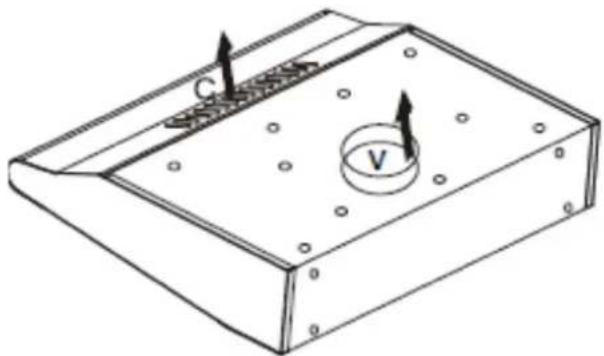
natural_image
Isometric technical drawing of a rectangular electronic component with labeled parts (C and V), showing internal structure and mounting holes (no text or symbols beyond labels)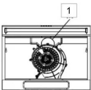
natural_image
Technical line drawing of a fan or fan assembly with labeled component 1 (no text or symbols beyond label)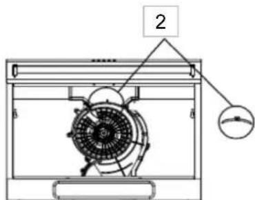
Do not remove the mode selection block (Fig. 1) for exhaust air operation.
For recirculation mode, remove the mode selection block (Fig. 2)
Attach the carbon filter securely and properly. Otherwise it can loosen and cause danger.
Use the carbon filter only in recirculation mode.

natural_image
Technical line drawing of a mechanical component with a circular base and internal gear-like structure (no text or symbols)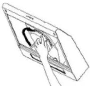
natural_image
Line drawing of a hand inserting a curved object into a rectangular device (no text or symbols)| Failure Cause | Solution | |
| Light on, but motor does not work | One flapp of the one-way valve is blocked. One-way valve not installed correctly | Eliminate the blocking or replace the one-way valve |
| The capacitor is damaged | Replace capacitor | |
| Motor bracket defective / jams | Replace motor | |
| Suspicious smell from the motor | Replace motor | |
| Beside the above mentioned actions, check the following: | ||
| Light does not work, motor does not run | Light damaged | Replace lights |
| No power, device cable not properly connected | Check fuse, connect cable correctly (electric diagram) | |
| Oil leakage | One-way valve leaking | Seal the junction with suitable means |
| Leakage from the junction of the chimney with the hood body | Seal the junction with suitable means | |
| Vibration of the hood | A flap of the on-wey valve is damaged and causing vibrations | Replace the complete one-way valve |
| The motor is not tightly mounted | Fix the hood tightly | |
| The hood is not tightly fixed | Fix the hood tightly | |
| Insufficient suction | The distance between the hood and the hob is too big | Lower the position of the hood |
| Too much air flow from open doors or windows | Close windows and doors | |
| The hood is instable | Mounting bracket not firmly fixed | Tighten the screws on the mounting bracket securely |
| Hood fastening screws not firmly tightened | Tighten the fastening screws firmly | |
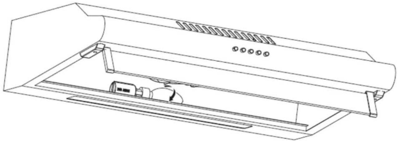
17. How to change the lamp
STANDARD COOKER HOOD
Respekta
CH 1259 IXC N
- Disconnect the hood from the electricity.
- Remove the grease filters.
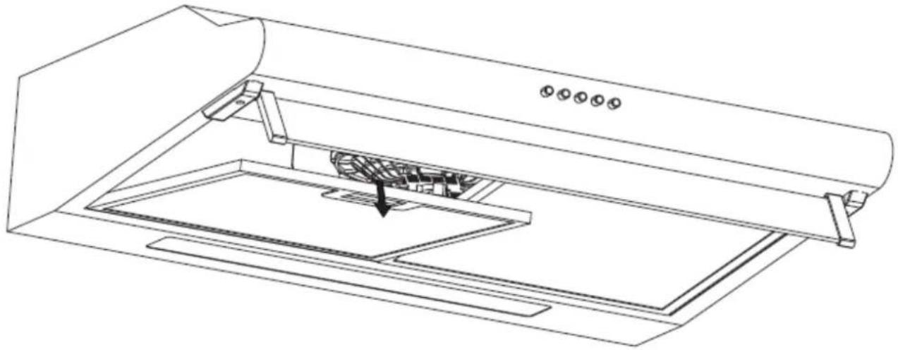
natural_image
Line drawing of a kitchen air purifier with a downward arrow indicating airflow direction (no text or symbols)- Rotate the LED bulb in direction shown in below Fig. Replace it by new one.
- Replace the bulb by new one.
natural_image
Line drawing of a technical diagram of an air duct system with ventilation slots and internal components (no text or labels)Technical data of the bulb:
Use only lamps with the here mentioned technical data.
Shape of the bulb:
Type: LED 15 LUX/W
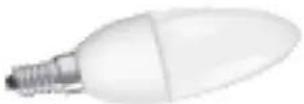
E14
18. GENERAL INSTALLATION INSTRUCTIONS STANDARD HOODS
1. Preparations
a) Determine the exact location for the hood.
b) Provide the power supply at the correct location.
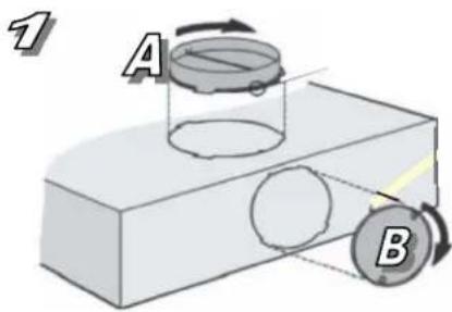
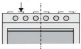
c) Now decide on the mode of operation (circulation or exhaust air mode) and prepare the hood accordingly. (Fig.1)
If you have decided upon exhaust air mode, all the appropriate core holes for routing the exhaust air hose must be executed or already present.
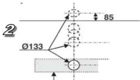
(Fig. 2) shows the different variants for core holes and the dimensions in mm to be observed.
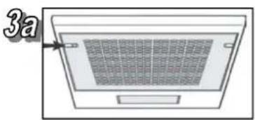
d) Remove the inlet air mesh (Fig. 3a) resp. grease filter (Fig. 3b) for later access to the inside of the hood.
e) Mount the flange (Fig. 1 A) to the opening through which the exhaust air is to be taken. (Where necessary change over the positions of the plastic cap (Fig. 1 B) and the flange (A))
natural_image
Diagram of a ventilation grille with a label '3a' pointing to the top panel (no text or symbols on the grille itself)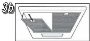
natural_image
Diagram of a roof structure with labeled components (no text or symbols)2. Wall mounting
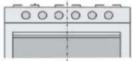
a) Using the supplied drilling template, drill the wall holes (4 holes 8 mm) (Fig. 4)
b) Insert the plugs in the drilled holes.
c) Screw 2 screws into the top plugs up to ca.5 mm.
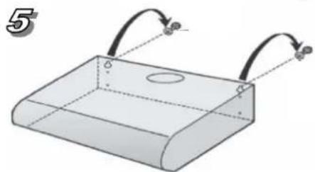
d) Hang the hood on the screws (Fig. 5)
e) From the inside, pass the locking screws through the rear wall of the hood and screw securely in the bottom plugs (Fig.6)
natural_image
3D diagram of a rectangular container with two curved arrows pointing outward from its top, no text or symbols present.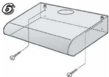
natural_image
3D diagram of a rectangular electronic component with mounting holes and screw placements (no text or symbols)3. Mounting to a wall unit (where intended for this)
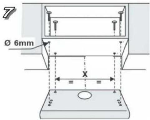
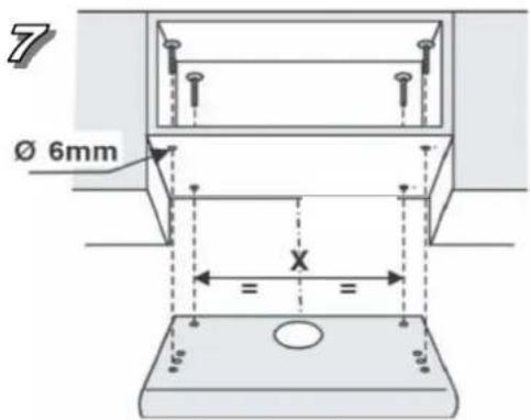
Drill the underside of the wall unit using the drilling template.
Fix the hood inside the wall unit with 4 screws (Fig. 7).
In the case of exhaust air hoods, an opening must be made in the wall unit for the exhaust air pipeline.
Circulation air hoods do not require this opening because with these the air is circulated through the slots at the front of the hoods.
-
Circulation air mode : Mount the carbon filter (Fig. 8) when using the circulation air mode.
-
Mounting the exhaust air hose: The exhaust air hose is mounted to the flange (Fig. 1 A) with a metal hose clip.
Images are for illustration purposes only.
The form and fittings of your hood can vary from the illustrations.
see chapter 11.1
natural_image
Pure mechanical assembly diagram showing a bracket with mounting holes and a downward arrow, no text or symbols present.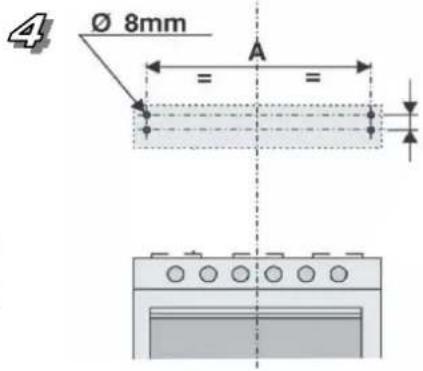
natural_image
Diagram of a mechanical device with a spherical component and curved arm, no text or symbols presentGARANTIEBEDINGUNGEN
The manufacturer does not take any responsibility for damage caused by the buyer.
This device has been manufactured and tested according to the latest methods. Irrespective of the seller's / dealer's statutory warranty obligation, the manufacturer provides a 6-month warranty for faultless material and faultless production for a period of 24 months from the date of purchase.
The warranty expires in case of intervention by the buyer or by third parties.
Damage caused by improper handling or operation, by incorrect installation or storage, by improper connection, improper installation, as well as by force majeure or other external influences, are not covered by the guarantee. We reserve the right to repair or replace defective parts or to exchange the device in case of complaints.
Only if repair (s) or replacement of the device, the intended use by the manufacturer should not be finally achieved, the buyer can demand warranty within six months, calculated from the date of purchase, reduction of the purchase price or cancellation of the purchase contract.
Claims for damages, including consequential damages, unless they are based on intent or gross negligence excluded.
In the case of unnecessary or unjustified use of the customer service, we charge the usual time and track charge for our service.
Complaints must be reported immediately after the detection of an error.
The replacement of light bulbs by our customer service technician is not subject to the guarantee guidelines and is therefore subject to a charge. There is no guarantee for bulbs.
The warranty claim has to be proven by the buyer, by presenting the purchase receipt. The guarantee is valid within the Federal Republic of Germany.
- Cooker hoods
- Respekta
- Modell
- Lieber Kunde,
- Störung- was tun wenn...
- GERÄTEBEDIENUNG
- STANDARD ABZUGSHAUBE
- Wandmontage
- Garantiebedingungen
- Standard Cooker hoods
- Chapter p age
- Explanation of information symbols
- The following symbol has the following significance:
- Dear customer,
- Declaration of conformity CE
- This is a warning symbol
- Warning
- Intended use
- Protection of the environment
- Packing
- Disposal
- Tips and general advice
- Before using the hood
- Using the hood
- Operating safety information
- In exhaust air mode:
- In circulation air mode:
- After-run function
- Cleaning and care
- Special information for appliances with tainless steel casing
- Changing the grease filter
- - Carbon filters
- Changing the lamps
- Changing LED lamp
- Fault – what to do if ...
- The motor fails to function:
- The hood capacity is insufficient / operating noise has increased:
- The lighting fails to function:
- Customer Service
- Installation
- Before installation of the appliance please pay regard to:
- Installation data
- Only connect the appliance to the power
- supply once it is properly installed.
- Using the extractor hood as an exhaust air hood (with air extracted to outdoors)
- Converting the extractor hood to a circulation hood
- Electrical connection
- Mounting the carbon filter
- Mounting the extractor hood
- Exhaust air pipeline
- English
- Operating- and Installation Instruction Cooker Hood
- Warranty
- COMPONENTS OF STANDARD COOKER HOODS
- EXHAUS AIR MODE (Factory setting)
- CHANGEOVER TO CIRCULATION AIR MODE
- Carbon filter required. (not included in delivery)
- APPLIANCE OPERATING
- STANDARD COOKER HOOD
- Recirculation mode
- How to change the lamp
- Technical data of the bulb:
- GENERAL INSTALLATION INSTRUCTIONS STANDARD HOODS
- Preparations
- Wall mounting
- Mounting to a wall unit (where intended for this)
- Images are for illustration purposes only.
Brand : Respekta
Model : Serie Tilla CH 1259 IXC N
Category : Cooker