
StructureScan HD Module - Sonar SIMRAD - Free user manual and instructions
Find the device manual for free StructureScan HD Module SIMRAD in PDF.


| Product Type | Fish Finder Module |
| Brand | Simrad |
| Model | StructureScan HD Module |
| Dimensions (L x W x H) | 7.5 x 4.3 x 2.2 inches |
| Weight | 1.2 lbs |
| Power Supply | 12 V DC (10.5 - 17 V) |
| Power Consumption | 10 W typical |
| Imaging Technology | StructureScan HD (Side and Down Scan) |
| Frequency | 455 kHz / 800 kHz |
| Maximum Depth | 300 ft (91 m) at 455 kHz |
| Connectivity | Ethernet, NMEA 2000 |
| Compatibility | Simrad NSS, NSO, NSE series displays |
| Transducer Included | No (sold separately) |
| Waterproof Rating | IPX7 |
| Operating Temperature | -15°C to 55°C (5°F to 131°F) |
| Mounting | Bracket or flush mount |
| Maintenance | Clean with damp cloth; avoid solvents |
| Safety | Disconnect power before installation; follow wiring guidelines |
| Spare Parts Availability | Contact Simrad dealer for cables, brackets |
| Warranty | 2 years limited |
Frequently Asked Questions - StructureScan HD Module SIMRAD
User questions about StructureScan HD Module SIMRAD
0 question about this device. Answer the ones you know or ask your own.
Ask a new question about this device
Download the instructions for your Sonar in PDF format for free! Find your manual StructureScan HD Module - SIMRAD and take your electronic device back in hand. On this page are published all the documents necessary for the use of your device. StructureScan HD Module by SIMRAD.
USER MANUAL StructureScan HD Module SIMRAD
As Navico is continuously improving this product, we retain the right to make changes to the product at any time which may not be reflected in this version of the manual. Please contact your nearest distributor if you require any further assistance.
It is the owner's sole responsibility to install and use the instrument and transducers in a manner that will not cause accidents, personal injury or property damage. The user of this product is solely responsible for observing safe boating practices.
NAVICO HOLDING AS AND ITS SUBSIDIARIES, BRANCHES AND AFFILIATES DISCLAIM ALL LIABILITY FOR ANY USE OF THIS PRODUCT IN A WAY THAT MAY CAUSE ACCIDENTS, DAMAGE OR THAT MAY VIOLATE THE LAW.
Governing Language: This statement, any instruction manuals, user guides and other information relating to the product (Documentation) may be translated to, or has been translated from, another language (Translation). In the event of any conflict between any Translation of the Documentation, the English language version of the Documentation will be the official version of the Documentation.
This manual represents the product as at the time of printing. Navico Holding AS and its subsidiaries, branches and affiliates reserve the right to make changes to specifications without notice.
Copyright
Copyright © 2012 Navico Holding AS.
Warning: It is your sole responsibility to install and use the instrument and transducer(s) in a manner that will not cause accidents, personal injury or property damage. Always observe safe boating practices.
Compliance Statements
Structure ScanTM HD complies with the following regulations:
- CE compliant under EMC Directive.
• C - Tick compliant as level 2 device.
Structure ScanTM HD also meets the technical standards in accordance with Part 15.103 of the FCC rules.
Warning
The user is cautioned that any changes or modifications not expressly approved by the party responsible for compliance could void the user's authority to operate the equipment.
This equipment has been tested and found to comply with the limits for a Class B digital device, pursuant to Part 15 of
the FCC rules. These limits are designed to provide reasonable protection against harmful interference in a residential installation. This equipment generates, uses and can radiate radio frequency energy and, if not installed and used in accordance with the instructions, may cause harmful interference to radio communications. However, there is no guarantee that the interference will not occur in a particular installation. If this equipment does cause harmful interference to radio or television reception, which can be determined by turning the equipment off and on, the user is encouraged to try to correct the interference by one or more of the following measures:
Reorient or relocate the receiving antenna Increase the separation between the equipment and receiver
Connect the equipment into an outlet on a circuit different from that of the receiver. Consult the dealer or an experienced technician for help.
Contents
2 Disclaimer
5 Introduction
5 Parts included in package
6 Required tools and supplies
6 StructureScan HD Indicator lights
7 Installation and Wiring
7 Selecting mounting location
8 Mounting the StructureScan HD module
8 Wiring
11 Specifications
11 Technical specifications
12 Spare parts and accessories
12 Spare parts
12 Assessories
13 Drawings
13 StructureScan HD module dimensions
1
Introduction
This document describes how to install the StructureScan™ HD black box module and connect the unit to transducers and display units.
Separate installation instruction for transducers are included with the transducer package.
Parts included with your StructureScan HD
For spare parts and part numbers, see Parts list page 12.
| Item No. Description | |
 | 1 StructureScan HD Black box module |
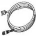 | 1 4 pin power cable |
 | 1 Fuse, 3A Automotive Type |
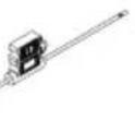 | 1 Fuse holder |
 | 2 Yellow Ethernet caps |
 | 1 Close end crimp connector |
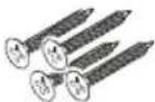 | 4 Phillips stainless steal screws (#8) |
| 1 Warranty | |
| 1 This manual | |
| 1 Manual translations DVD |
Required tools and supplies
| Drill | 2 mm (5/64") Drill Bit | Phillips screw driver Pencil |
StructureScan HD Indicator lights
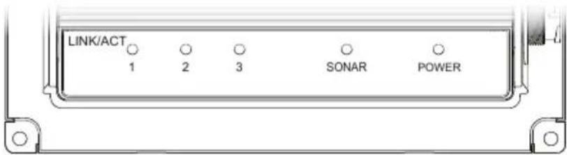
| Ind. Status | Description | |
| 1, 2 and 3 | Off | No Ethernet communication (cable unplugged, bad cable or remote unit not powered) |
| Flashing - yellow | Ethernet communication is working (link/active light) | |
| Sonar | Off | Transducer not connected or cable/transducer is broken |
| On - Green | Transducer detected/locked on to bottom | |
| Flashing - green | Transducer detected/not locked on to bottom | |
| Power | Off | No power or not switched on (check yellow wire) |
| On - Red System | booting | |
| On - Green System | em operating | |
| Slow flashing - Red/green | Product in factory mode; Ethernet communication working | |
| Fast flashing - Red/green | Product in factory mode; no Ethernet communication (cable unplugged or bad cable) |


natural_image
Line drawing of a screwdriver with a pointed tip and threaded shaft (no text or symbols)
natural_image
Line drawing of a pencil with eraser (no text or symbols)2
Installation and Wiring
The StructureScan HD black box module connects between the transducer and display unit, or via a network switch.
Before installing the module, consider location and cable runs necessary to connect the module to the display unit and power source.
Do not run the transducer cabling near the module DC power cables or any VHF antenna coax or power cables for the VHF.
The module conforms to the appropriate Electromagnetic Compatibility (EMC) standards; but proper installation is required to get the best use and performance from this product.
Selecting mounting location
When installing the module certain factors that could affect its operation should be considered. Ensure you have as much separation as possible between different electrical equipment, (see diagram).

Make sure the transducer cable is long enough to connect to the module. If not, an extension cable is available (only one extension is recommended for optimal performance). For transducer cable length see Spare parts and accessories, page 12.

natural_image
Isometric line drawing of a device with labeled components and directional arrows (no text or symbols)Mounting the StructureScan HD module
Preferably mount the StructureScan HD black box module on a vertical surface so that cables exit sideways. If that is not feasible, create drip loops to prevent moisture entering the connectors.
natural_image
Technical diagram of a heat exchanger unit with labeled ports and connectors (no readable text or symbols)
natural_image
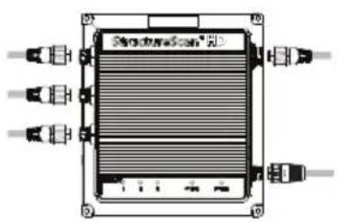
Technical diagram of a rectangular electronic device with three input/output ports and wiring (no text or symbols)Fasten the module by using the screws included with the unit. Secure cables and ensure to not put strain in the connectors.
Wiring
Refer to the Wiring diagram on page 10.
⚠ Warning: Removing the transducer cable from the StructureScan HD module while it is powered on can cause sparks. Remove the transducer cable only after the module has been disconnected from its power source.
Connecting the module to your display
The module connects to your display over an Ethernet network, either directly or via an Ethernet network switch.

natural_image
Technical line drawing of a vehicle's front and side views (no text or symbols)Connecting the transducer
The StructureScan transducer connects to the module with the cable supplied with the transducer.
On boats with large dead rise angle two StructureScan transducers can be used. They are connected to the module by using the optional Y cable. Connect the transducers according to the labeling on the Y-cable.

Power connection
The unit will turn on when power is applied.
It is recommended to connect the module to a Power control bus (A), and set your unit to power control master.
Alternatively the unit can be powered directly from the vessel's battery (B).
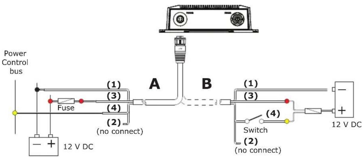
| Pin/Item Color Signal | |||
 | 1 Black 12 V battery - | ||
| 2 Blue NC | |||
| 3 Red 12V battery + | |||
| 4 Yellow Ignition sense | |||
Note: If the black box module is connected directly to the vessel's battery, the module will continue to draw power even when it is not in operation. It is recommended that the yellow power cable wire be fitted with an optional on/off switch, allowing the module to be powered off when not in use.

flowchart
graph TD
    A["Device A"] -->|To display unit| P["Central Device"]
    P -->|To display unit| A
    P -->|PWR| B["Output 1"]
    P -->|PWR| B
    P -->|PWR| B
    P -->|PWR| B
    P -->|PWR| B
    P -->|PWR| B
    P -->|PWR| B
    P -->|PWR| B
    P -->|PWR| B
    P -->|PWR| B
    P -->|PWR| B
    P -->|PWR| B
    P -->|PWR| B

    subgraph Input_Units
        A2["Input A"] --> P
        B2["Input B"] --> P
        C2["Input C"] --> P
        D2["Input D"] --> P
        E2["Input E"] --> P
        F2["Input F"] --> P
        G2["Input G"] --> P
        H2["Input H"] --> P
        I2["Input I"] --> P
        J2["Input J"] --> P
        K2["Input K"] --> P
        L2["Input L"] --> P
        M2["Input M"] --> P
        N2["Input N"] --> P
        O2["Input O"] --> P
        P2["PWR"] --> P
        P2 -->|C or| P
        P2 -->|B or| P
    end
| Reference Description |
| A Ethernet cable |
| B StructureScan Transducer cable |
| C StructureScan Y-cable (option) |
For part numbers, see Spare parts and assessories on page 12.
3
Specifications
Technical specifications
| Mechanical | |
| Dimensions See page 13 | |
| Weight 0.8 kg (1.8lbs) | |
| Material Plastic/Aluminum | |
| Environmental | |
| Operating temperature -1 | 5° - +55°C (5° - 131°F) |
| Storage temperature -40° | - +85°C (-40° - 185°F) |
| Waterproof integrity IPx7 | |
| Notified compliance CE, FCC, C-Tick, RoHS | |
| Electrical | |
| Power supply 12V DC | |
| Voltage input 10 - 17 V DC | |
| Fuse | External: 3A Fast Acting Automotive Blade |
| Transmit power WRMS: 500W; WPK: 4000W | |
| Current drain | Max: 0.75 A; Typical: 0.60 A; Inrush: 4.7 A pk |
| Communication | |
| Ethernet 3 ports | |
| Shared device support 3 | |
| Transducer | |
| Number of devices support | 1 |
| Frequencies 455kHz | |
4
Spare parts and accessories
Spare parts
| Item Part no. | Description | |
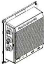 | 000-10801-001 StructureScan HD module | |
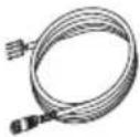 | 032-0055-08 4 pin power cable | |
Assessories
| Item Part no. | Description | |
 | 000-10802-001 | StructureScan Skimmer mount transducer, including 6 m (20 ft) cable |
 | 000-00099-006 | Transducer Extension cable, 3 m (10 ft) |
 | 032-0264-02 | StructureScan Y-cable, 0.3 m (11.8") |
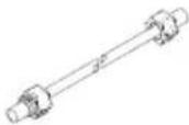 | 000-0127-51 Ethernet cable, 1.8 m (6 ft) | |
| 000-0127-29 Ethernet cable, 4.6 m (15 ft) | ||
| 000-0127-30 Ethernet cable, 7.6 m (25 ft) | ||
| 000-0127-37 Ethernet cable, 15.2 m (50 ft) | ||
| 000-0124-70 | Kit of 4 replacement caps for connectors | |
5
Drawings
StructureScan HD module dimensions


LOWRANCE®
SIMRAD
B&G
- Copyright
- Compliance Statements
- Warning
- Contents
- Introduction
- Installation and Wiring
- Specifications
- Spare parts and accessories
- Drawings
- 1
- Introduction
- Parts included with your StructureScan HD
- Required tools and supplies
- StructureScan HD Indicator lights
- 2
- Installation and Wiring
- Selecting mounting location
- Mounting the StructureScan HD module
- Wiring
- Connecting the module to your display
- Connecting the transducer
- Power connection
- 3
- Specifications
- 4
- Spare parts and accessories
- 5
- Drawings
- StructureScan HD module dimensions
Brand : SIMRAD
Model : StructureScan HD Module
Category : Sonar