
StructureScan 3D Thru-Hull - Sonar SIMRAD - Free user manual and instructions
Find the device manual for free StructureScan 3D Thru-Hull SIMRAD in PDF.


| Product Type | Thru-Hull Transducer |
| Brand | Simrad |
| Model | StructureScan 3D Thru-Hull |
| Category | Fish Finder Transducer |
| Mounting Type | Thru-Hull |
| Frequency | 455 kHz / 800 kHz |
| Max Depth | 300 m (984 ft) |
| Beam Angle | 135° (SideScan) / 60° (DownScan) |
| Housing Material | Plastic (Polyurethane) |
| Dimensions (Diameter) | 3.5 in (89 mm) |
| Dimensions (Height) | 4.2 in (107 mm) |
| Weight | 0.5 kg (1.1 lbs) |
| Power Supply | 12-24 V DC |
| Power Consumption | 10 W typical |
| Cable Length | 10 m (33 ft) |
| Connector Type | 8-pin SIMRAD connector |
| Temperature Range | -20°C to +70°C (-4°F to 158°F) |
| Key Features | 3D Real-Time StructureScan imaging, SideScan and DownScan |
| Cleaning | Rinse with fresh water after use. Do not use abrasive cleaners. |
| Maintenance | Check for fouling or damage periodically. Replace if cracked. |
Frequently Asked Questions - StructureScan 3D Thru-Hull SIMRAD
User questions about StructureScan 3D Thru-Hull SIMRAD
0 question about this device. Answer the ones you know or ask your own.
Ask a new question about this device
Download the instructions for your Sonar in PDF format for free! Find your manual StructureScan 3D Thru-Hull - SIMRAD and take your electronic device back in hand. On this page are published all the documents necessary for the use of your device. StructureScan 3D Thru-Hull by SIMRAD.
USER MANUAL StructureScan 3D Thru-Hull SIMRAD
Thru-Hull with Anti-rotation Hardware
StructureScan™ Transducers
Models: SS70, SS141L, SS147
INSTALLATION INSTRUCTIONS
Record the information found on the cable tag for future reference.
PN: Date Frequency kHz
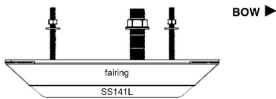
Follow the precautions below for optimal product performance and to reduce the risk of property damage, personal injury, and/or death.
WARNING: Installation of the anti-rotation studs/screws is mandatory! The anti-rotation studs/screws hold the fairing firmly in place. Failure to install the anti-rotation studs/ screws may result in the fairing rotating while the boat is underway. The effect may be violent movement and loss of steering.
WARNING: The transducer must be installed parallel to the keel/centerline to ensure proper boat handling and water flow under the transducer.
WARNING: Always wear safety glasses, a dust mask, and ear protection when installing.
WARNING: Immediately check for leaks when the boat is placed in the water. Do not leave the boat in the water unchecked for more than three hours. Even a small leak may allow a considerable amount of water to accumulate.
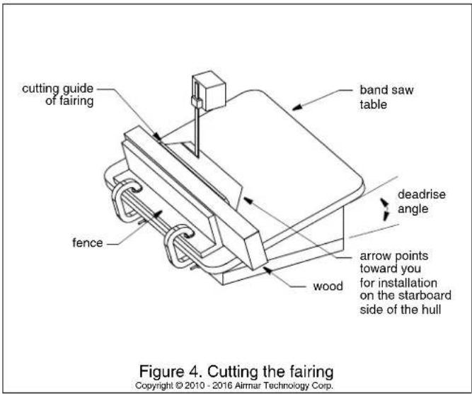
WARNING: SS70, SS141L with Fairing—The fairing must be screwed to a block of wood before cutting. It is too thin to cut safely without additional material. Failure to do so may result in the fairing moving on the band saw.
WARNING: Fairing—Do not install a fairing that has been mis-cut. Replace it.
- Cutting the fairing at an angle greater than the maximum allowed will cut into the transducer and/or anti-rotation pockets, thus weakening the fairing.
- Do not allow any gap between the fairing and the hull that is greater than 1.5mm (1/16"). When the boat is underway, water will enter any gaps and push against the fairing with considerable force, possibly rotating it.
WARNING: Fiberglass hull—The transducer must be installed in solid fiberglass, not in coring.
CAUTION: Never install a metal transducer on a vessel with a positive ground system.
CAUTION: Never pull, carry, or hold the transducer by the cable as this may sever internal connections.
CAUTION: Never strike the transducer.
CAUTION: Stainless steel transducer in a metal hull—Stainless steel must be isolated from a metal hull to prevent electrolytic corrosion. Use the isolation sleeving supplied.
CAUTION: Transducer Pair—Be sure to connect the port-side transducer and the starboard-side transducer to the correct terminals on the StructureScan module. If the transducers are connected in reverse, the display will not work properly.
CAUTION: SS147—The transducer must be installed on a nearly flat hull behind a step. Do not install on a V-hull. Do not install with a fairing. If the transducer protrudes below the hull on a fairing, it will be susceptible to impact that may damage the transducer and void the warranty. If a fairing is needed, install an SS70 or SS141L.
CAUTION: Never use solvents. Cleaner, fuel, sealant, paint, and other products may contain solvents that can damage plastic parts, especially the transducer's face.
IMPORTANT: Read the instructions completely before proceeding with the installation. These instructions supersede any other instructions in your instrument manual if they differ.
Applications
- Stainless steel is compatible with all hull materials. Recommended for aluminum hulls to prevent electrolytic corrosion, provided the stainless steel transducer is isolated from the metal hull.
- Recommended for boats capable of speeds up to 30kn (35MPH). Optimal speed is 1.5 - 8.5 kn (2 - 10MPH).
- SS70, SS141L—A fairing is strongly recommended if the deadrise angle of the hull exceeds 10^ . The fairing can accommodate a deadrise angle of up to 22^ .
- SS70, SS141L—On a boat with a steep deadrise angle, a pair of transducers, one on the port side and one on the starboard side, can be installed and connected to the StructureScan module.
- SS147—Intended for stepped hulls, to be installed on a flat area behind a step.
Identify Your Model
The model name is printed on the cable tag.

Tools & Materials
Safety glasses
Dust mask
Ear protection
Angle finder (installation with fairing)
Band saw (installation with fairing)
Block of wood (installation with fairing) min. 4" x 4" x 18"
Screws (4) (installation with fairing) No. 8
Screwdrivers
Rasp or power tool (installation with fairing)
Electric drill
Drill bits and hole saws:
Pilot hole 3mm or 1/8"
SS70 transducer stem 38mm or 1-1/2"
SS141L, SS147 transducer stem 25mm or 1"
SS70, SS141L anti-rotation studs
in solid fiberglass or wood hull 9mm or 11/32"
SS70, SS141L anti-rotation studs in metal hull 10mm or 3/8"
SS147 anti-rotation screws 8mm or 5/16"
Sandpaper
Mild household detergent or weak solvent (such as alcohol)
File (installation in metal hull)
Marine sealant (suitable for below waterline)
Slip-joint pliers
Grommet(s) (some installations)
Cable ties
Water-based anti-fouling paint (mandatory in salt water)
Installation in a cored fiberglass hull: (see page 7)
Drill bits and hole saws for hull interior:
SS70 transducer stem 51mm or 2"
SS141L, SS147 transducer stem 38mm or 1-1/2"
SS70, SS141L anti-rotation studs 19mm or 3/4"
SS147 anti-rotation screws 12mm or 1/2"
Cylinder, wax, tape, and casting epoxy
Mounting Location
Guidelines
CAUTION: Do not mount in line with or near water intake or discharge openings or behind strakes, struts, fittings, or hull irregularities that will disturb the water flow.
CAUTION: Do not mount the sensor where the boat may be supported during trailering, launching, hauling, or storage to avoid damaging the transducer's face.
- The water flowing under the hull must be smooth with a minimum of bubbles and turbulence (especially at high speeds).
- The transducer must be continuously immersed in water.
- The transducer beam must be unobstructed by the keel or propeller shaft(s).
- Choose a location away from interference caused by power and radiation sources such as: the propeller(s) and shaft(s), other machinery, other echosounders, and other cables. The lower the noise level, the higher the echosounder gain setting that can be used.
- Choose an accessible spot inside the vessel with adequate space for the height of the stem and tightening the nuts.
- SS70, SS141L—Choose a location with a minimal deadrise angle. If the hull has a steep deadrise, mount a pair of transducers.
- Pair of SS70, SS141L—Mount the transducers across from one another on opposite sides of the centerline (keel) (see Figure 1).
- SS147—Choose a location that is nearly flat from front to back (see Figure 2). Install behind a step.
Boat Types (see Figure 1)
- Planing hull powerboat—Mount well aft near the centerline and well inboard of the first set of lifting strakes to insure that it is in contact with the water at high speeds. The starboard side of the hull where the propeller blades are moving downward is preferred.
Outboard and I/O—Mount just forward and to the side of the engine(s). Inboard—Mount well ahead of the propeller(s) and shaft(s).
Stepped hull—Mount just ahead of the first step.
- Displacement hull powerboat—Locate 1/3 of the way along the LWL and 150–300mm (6–12") off the centerline. The starboard side of the hull where the propeller blades are moving downward is preferred.


Figure 3. SS70, SS141L: Deadrise angle and fairing thickness Copyright © 2010 - 2016 Airmar Technology Corp.
SS70, SS141L Installation
NOTE: If you are installing the transducer with NO fairing, disregard all references to a fairing and backing block. Skip to "Hole Drilling" on page 3.
Cutting the Fairing
CAUTION: The arrow on the fairing points forward toward the bow when installed. Be sure to orient the fairing on the band saw, so the angle cut matches the intended side of the hull and not the mirror image.
CAUTION: Shape the fairing to the hull as precisely as possible. If there are gaps between the fairing and the hull near the ends, cut a new fairing. Over tightening the rods to minimize gaps may crack the transducer and/or crush the fairing.
- Metal hull—The holes for the anti-rotation studs must be enlarged to accommodate the isolation sleeving. Using a 10mm (3/8") drill bit, enlarge the two holes in the fairing.
- Measure the deadrise angle of the hull at the selected mounting location using an angle finder or a digital level (see Figure 3)
- Tilt the band saw table to the measured angle and secure the cutting fence (see Figure 4).
- Fasten the fairing to the center of the block of wood using the four corner holes and No. 8 screws.
- Place the fairing on the table so the cutting guide rests against the fence. The arrow will be pointing toward you for installation on the starboard side of the boat or away from you for installation on the port side (see Figure 5).
- Adjust the cutting fence, so the fairing will be cut in about two equal parts (see Figure 3). The section that will become the fairing must be a minimum of 7mm (9/32") at its thinnest dimension. This number corresponds to the flange on the fairing.
- Recheck steps 1 through 5. Then cut the fairing.
- Check the fit of the fairing by placing it against the hull, being sure it is parallel to the centerline of the boat (keel). Hold the fairing on the ends and try to rock it back and forth. Shape the fairing to the hull as precisely as possible with a rasp or power tool until it no longer rocks.
- Remove the fairing from the block of wood.
- Use the remaining section of the fairing with the cutting guide as the backing block.
Hole Drilling
Cored fiberglass hull—Follow separate instructions on page 7.
-
Locate and drill the holes for the transducer stem and anti-rotation studs, using the fairing as a guide (see Figure 5, 6, 7, or 8). Align the fairing parallel to the centerline of the boat (keel) with the arrow facing forward toward the bow.
-
Drill 3mm (1/8") pilot holes for the transducer stem and the two anti-rotation studs.
- Using the appropriate drill bits/hole saw, drill the holes for the transducer stem and the two anti-rotation studs.
Fairing—Drill through the holes in the fairing to be sure the holes are drilled perpendicular to the waterline and not at the angle of the hull.
NO Fairing—Be sure to drill the holes perpendicular to the hull.
- Sand and clean the area around the holes, inside and outside, to ensure the marine sealant will adhere properly to the hull. If there is any petroleum residue inside the hull, remove it with either a mild household detergent or a weak solvent (alcohol) before sanding.
Metal hull—Remove all burrs with a file and sandpaper.

Figure 5. SS70, SS141L: Bedding and installing with a fairing in a fiberglass or wood hull Copyright © 2012 - 2016 Airmar Technology Corp.
Bedding
CAUTION: Be sure all surfaces to be bedded are clean and dry.
CAUTION: When installing the anti-rotation studs, use slip-joint pliers placed near the bottom of the stud. Do not use pliers farther up, as this will damage the threads.
- Remove the hull nut (see Figure 5, 6, 7, or 8).
- Apply a 2mm (1/16") thick layer of marine sealant to the surface of the transducer that will contact the hull/fairing and up the stem. The sealant must extend 6mm (1/4") higher than the combined thickness of the hull, fairing and backing block (if used), and the hull nut. This will ensure there is marine sealant in the threads to seal the hull and hold the hull nut securely in place.
- Apply a 2mm (1/16") thick layer of marine sealant around the anti-rotation studs including the bottom. This will ensure there is marine sealant in the threads to secure the studs in the transducer, seal the hull, and hold the nut securely in place.
- Screw the anti-rotation studs into the holes in the transducer. Using slip-joint pliers placed near the bottom of the stud, tighten
each one in turn. Do not use pliers farther up, as this will damage the threads.
-
Metal hull—Use the isolation sleeving to cover the transducer stem and the two anti-rotation studs. Cut the length of each sleeve greater than the thickness of the hull. Note that the sleeves must not interfere with tightening the nuts. Slide the larger diameter isolation sleeve over the bedded transducer stem. Slide the two remaining isolation sleeves over the bedded anti-rotation studs. Slide the sleeves as far down as possible. Apply a 2mm (1/16") thick layer of the marine sealant to the outside of the three isolation sleeves.
-
Fairing—Thread the transducer cable through the fairing. Seat the transducer firmly within the recess in the fairing. Apply a 2mm (1/16") thick layer of marine sealant to the following surfaces:
• Fairing that will contact the hull
- Backing block that will contact the hull
- Hull nut that will contact the backing block
- Washers for the anti-rotation studs that will contact the backing block


Figure 7. SS70, SS141L: Bedding and installing WITHOUT a fairing in a fiberglass or wood hull Copyright © 2013 - 2016 Almar Technology Corp.
Installing
CAUTION: Do not over-tighten the nuts possibly damaging the transducer or fairing.
- From outside the hull, thread the cable through the mounting hole (see Figure 5, 6, 7, or 8).
- Push the stem of the transducer and the anti-rotation studs through the hull.
- From inside the hull:
- Fairing—Slide the backing block and the hull nut onto the cable. Seat the backing block firmly against the hull. Screw the hull nut in place and tighten it with slip-joint pliers. Do not over-tighten. With the bedded side down, slide one washer and nut onto each anti-rotation stud. Tighten the nuts one full turn only with slip-joint pliers. Do not over-tighten.
Cored fiberglass hull—Do not over-tighten crushing the hull.
Wood hull—Allow for the wood to swell before tightening.
Metal hull—Be sure the isolation sleeves are between the transducer stem/studs and the hull. The isolation sleeves must be below the nuts to prevent the sleeves from interfering with tightening the nuts. Trim the sleeves if necessary.
- NO fairing—Slide the rubbery washer and hull nut onto the cable. Seat the rubbery washer firmly against the hull. Screw the hull nut in place and tighten it with slip-joint pliers. Do not over-tighten. Slide the rubbery washer, metal washer, and nut onto each anti-rotation stud. Seat the rubbery washer firmly against the hull. Tighten the nuts one full turn only with slip-joint pliers. Do not over-tighten. Cored fiberglass hull—Do not over-tighten crushing the hull. Wood hull—Allow for the wood to swell before tightening. Metal hull—Be sure the isolation sleeves are between the transducer stem/studs and the hull. The isolation sleeves must be below the nuts to prevent the sleeves from interfering with tightening the nuts. Trim the sleeves if necessary.
- Fairing—When the boat is underway, especially at high speeds, water will enter any gaps and push against the fairing with considerable force, possibly rotating it. Fill any gaps between the fairing and the hull with marine sealant. If there is any gap greater than 1.5mm (1/16"), replace the fairing.
- Remove any excess marine sealant on the outside of the hull, transducer, and fairing if used to ensure smooth water flow under the transducer.

Figure 8. SS70, SS141L: Bedding and installing WITHOUT a fairing in a metal hull Copyright © 2012 - 2016 Airmar Technology Corp.
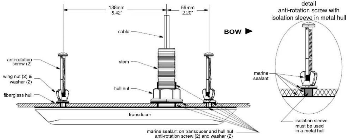
Figure 9. SS147: Bedding and installing Copyright © 2012 - 2016 Airmar Technology Corp.
SS147 Installation
CAUTION: Do not install with a fairing.
Hole Drilling
Cored fiberglass hull—Follow separate instructions on page 7.
- Be sure the holes for the anti-rotation screws are oriented so the one closest to the stem is facing forward toward the bow (see Figure 9). Using a straight edge held parallel to the centerline (keel) of the boat, mark the centers of the three holes.
- Be sure the holes are drilled perpendicular to the hull.
- Drill 3mm (1/8") pilot holes for the transducer stem and the two anti-rotation screws.
- Using the appropriate drill bits/hole saw, drill the holes for the transducer stem and the two anti-rotation screws.
- Sand and clean the area around the holes, inside and outside, to ensure the marine sealant will adhere properly to the hull. If there is any petroleum residue inside the hull, remove it with either a mild household detergent or a weak solvent (alcohol) before sanding.
Metal hull—Remove all burrs with a file and sandpaper.
Bedding
CAUTION: Be sure all surfaces to be bedded are clean and dry.
- Apply a 2mm (1/16") thick layer of marine sealant to the surface of the transducer that will contact the hull and up the stem (see Figure 9). The sealant must extend 6mm (1/4") higher than the combined thickness of the hull and hull nut. This will ensure there is marine sealant in the threads to seal the hull and hold the hull nut securely in place.
- Apply a 2mm (1/16") thick layer of marine sealant around the anti-rotation screws including the bottom. This will ensure there is marine sealant in the threads to secure the screws in the transducer, seal the hull, and hold the nut securely in place.
- Screw a wing nut onto each anti-rotation screw and spin it toward the head. Note that the wing nuts should be upside down.
-
Apply a 2mm (1/16") thick layer of marine sealant to the surface of the hull nut that will contact the hull.
-
Apply a 2mm (1/16") thick layer of marine sealant to the surface of the washers that will contact the hull. Slide a washer onto each anti-rotation screw with the bedded side facing away from the wing nut.
- Metal hull—Use the isolation sleeving to cover the transducer stem and the two anti-rotation screws. Cut the length of each sleeve the thickness of the hull. Note that the sleeves must not interfere with tightening the nuts. Slide the larger diameter isolation sleeve over the bedded transducer stem. Slide the two remaining isolation sleeves over the bedded anti-rotation screws. Slide the sleeves as far down as possible. Apply a 2mm (1/16") thick layer of the marine sealant to the outside of the three isolation sleeves.
Installing
CAUTION: Do not over-tighten the nuts possibly damaging the transducer.
- From outside the hull, thread the cable through the mounting hole.
- Push the stem of the transducer through the mounting hole (see Figure 9). Seat the transducer firmly against the hull. Screw the hull nut in place and tighten it with slip-joint pliers. Do not over-tighten.
Cored fiberglass hull—Do not over-tighten crushing the hull.
Wood hull—Allow for the wood to swell before tightening.
Metal hull—Be sure the isolation sleeve is between the transducer stem and the hull. The isolation sleeve must be below the hull nut to prevent the sleeve from interfering with tightening the nut. Trim the sleeve if necessary.
- Using a screwdriver, screw the anti-rotation screws with the wing-nuts and washers in place into the transducer until the screws stop turning. Do not apply additional pressure. Hand-tighten the wing nuts. Do not over-tighten.
Cored fiberglass hull—Do not over-tighten crushing the hull.
Wood hull—Allow for the wood to swell before tightening.
Metal hull—Be sure the isolation sleeves are between the anti-rotation screws and the hull. The isolation sleeves must be below the wing nuts to prevent the sleeves from interfering with tightening the nuts. Trim the sleeves if necessary.
- Remove any excess marine sealant on the outside of the hull to ensure smooth water flow under the transducer.

flowchart
graph TD
    A["StructureScan HD LSS-2 module"] --> B["Y-cable"]
    A --> C["starboard"]
    A --> D["starboard cable"]
    A --> E["port cable"]
    A --> F["single transducer cable"]
Figure 10. SS141L: Connecting the transducer(s) Copyright © 2010 - 2016 Navico Holding AS
Cable Routing & Connecting
CAUTION: Do not remove the connector(s) to ease cable routing. If a cable must be cut and spliced, use Airmar's splash-proof Junction Box No. 33-035 and follow the instructions provided. Removing the waterproof connector or cutting the cable, except when using a water-tight junction box, will void the sensor warranty.
- Route the transducer cable(s) to the StructureScan LSS-2 or 3D module being careful not to tear the cable jacket when passing it through the bulkhead(s) and other parts of the boat. Use grommets to prevent chafing. To reduce electrical interference, separate the transducer cable(s) from other electrical wiring and the engine.
- Follow the appropriate graphic to connect one transducer or a pair of transducers (see Figure 10 or 11).
Pair of SS141L transducers—Using the Y-cable, be sure to connect the port-side transducer to the port cable and the starboard-side transducer to the starboard cable. Then connect the Y-cable to the StructureScan HD LSS-2 module.
Pair of SS70 transducers—On the StructureScan 3D module, be sure to connect the cable from the port-side transducer to the terminal labeled Transducer 1. Connect the cable from the starboard-side transducer to the terminal labeled Transducer 2.
- Coil any excess cable and secure it in place with cable ties to prevent damage.
- Refer to the instructions that came with the StructureScan LSS-2 or 3D module to connect it to the display and the power supply.
Checking for Leaks
When the boat is placed in the water, immediately check around the transducer(s) for leaks. Note that very small leaks may not be readily observed. Do not leave the boat in the water for more than 3 hours before checking it again. If there is a small leak, there may be considerable bilge water accumulation after 24 hours. If a leak is observed, repeat "Bedding" and "Installing" immediately.
Installation in a Cored Fiberglass Hull
The core (wood or foam) must be cut and sealed carefully. The core must be protected from water seepage, and the hull must be reinforced to prevent it from crushing under the hull nut allowing the transducer(s) to become loose.
CAUTION: Completely seal the hull to prevent water seepage into the core.

flowchart
graph TD
    A["3D StructureScan"] --> B["Transducer 1 terminal"]
    A --> C["Transducer 2 terminal"]
    B --> D["port-side transducer"]
    C --> E["starboard-side transducer"]
    D --> F["pair"]
    E --> G["single"]
    H["Y-cable"] --> I
Figure 11. SS70: Connecting the transducer(s) Copyright © 2018 Almar Technology Corp.
- Drill a 3mm or 1/8" pilot hole perpendicular to the waterline from inside the hull (see Figure 12). If there is a rib, strut, or other hull irregularity near the selected mounting location, drill from the outside. If the hole is drilled in the wrong location, drill a second
hole in a better location. Apply masking tape to the outside of the hull over the incorrect hole and fill it with epoxy. - Using the appropriate size drill bit/hole saw, cut a hole from outside the hull through the outer skin only. Be sure to hold the drill plumb, so the hole will be perpendicular to the water surface.
- The optimal interior hole diameter is affected by the hull's thickness and deadrise angle. It must be large enough in diameter to allow the core to be completely sealed.
- Using the drill bit/hole saw for the hull interior, cut through the inner skin and most of the core from inside the hull keeping the drill perpendicular to the hull. The core material can be very soft. Apply only light pressure to the drill bit after cutting through the inner skin to avoid accidentally cutting the outer skin.
- Remove the plug of core material so the inside of the outer skin and the inner core of the hull is fully exposed. Sand and clean the inner skin, core, and the outer skin around the hole.
- Coat a hollow or solid cylinder of the correct diameter with wax and tape it in place. Fill the gap between the cylinder and hull with casting epoxy. After the epoxy has set, remove the cylinder.
- Sand and clean the area around the hole, inside and outside, to ensure that the sealant will adhere properly to the hull. If there is any petroleum residue inside the hull, remove it with either

Figure 12. Preparing a cored fiberglass hull Copyright © 2005 Aimar Technology Corp.
mild household detergent or a weak solvent (alcohol) before sanding.
- Follow the same procedure to prepare the hull for each anti-rotation stud/screw (steps 1 through 6).
- Proceed with "Bedding" on page 3 for either the SS70 and SS141L or page 6 for the SS147.
Anti-fouling Paint
Surfaces exposed to salt water must be coated with anti-fouling paint. Use water-based anti-fouling paint only. Never use ketone-based paint since ketones can attack many plastics possibly damaging the transducer. Reapply anti-fouling paint every 6 months or at the beginning of each boating season.
Maintenance, Parts & Replacement
Cleaning
Aquatic growth can accumulate rapidly on the transducer's surface reducing its performance within weeks. Clean the surface with a Scotch-Brite® scour pad and mild household detergent taking care to avoid making scratches. If the fouling is severe, lightly wet sand with fine grade wet/dry paper.
Replacement Parts
The information needed to order a replacement transducer is printed on the cable tag. Do not remove this tag. When ordering, specify the part number, date, and frequency in kHz. For convenient reference, record this information on the top of page 1.
Lost, broken, and worn parts should be replaced immediately.
| Model Fairing Hull Nut | Y-Cable | |
| SS70 33-722-01 02-071-01 — | ||
| SS141L 33-650-01 02-149-01 22-1210-01 | ||
| SS147 — 02-149-01 — | ||
Obtain parts from a local sales office, the website below, or a marine dealer.
www.lowrance.com or www.simrad-yachting.com
StructureScan ^™ is a trademark of Navico Holding AS.
- INSTALLATION INSTRUCTIONS
- Applications
- Identify Your Model
- Tools & Materials
- Mounting Location
- Guidelines
- Boat Types (see Figure 1)
- SS70, SS141L Installation
- Cutting the Fairing
- Hole Drilling
- Bedding
- Installing
- SS147 Installation
- Cable Routing & Connecting
- Checking for Leaks
- Installation in a Cored Fiberglass Hull
- Anti-fouling Paint
- Maintenance, Parts & Replacement
- Cleaning
- Replacement Parts
Brand : SIMRAD
Model : StructureScan 3D Thru-Hull
Category : Sonar