
SP36555 - Fitness Equipment COSTWAY - Free user manual and instructions
Find the device manual for free SP36555 COSTWAY in PDF.


| Product Type | Magnetic Resistance Exercise Bike |
| Model | SP36555 |
| Brand | Costway |
| Dimensions (L x W x H) | 40 x 21 x 46 inches (approx.) |
| Weight | 59 lbs (27 kg) |
| Max User Weight | 265 lbs (120 kg) |
| Resistance Type | Magnetic, 8-level adjustable |
| Power Source | Self-powered (no electricity required) |
| Display | LCD monitor showing time, speed, distance, calories, and odometer |
| Seat Adjustment | Vertical and horizontal adjustable seat |
| Pedals | Adjustable toe cages for secure foot placement |
| Frame Material | Heavy-duty steel frame |
| Transport Wheels | Built-in front transport wheels for easy mobility |
| Water Bottle Holder | Yes, included |
| Assembly Required | Yes, tools included |
| Warranty | 1-year limited warranty |
| Certification | CE and RoHS certified |
Frequently Asked Questions - SP36555 COSTWAY
User questions about SP36555 COSTWAY
0 question about this device. Answer the ones you know or ask your own.
Ask a new question about this device
Download the instructions for your Fitness Equipment in PDF format for free! Find your manual SP36555 - COSTWAY and take your electronic device back in hand. On this page are published all the documents necessary for the use of your device. SP36555 by COSTWAY.
USER MANUAL SP36555 COSTWAY
natural_image
Line drawing of a gym machine with adjustable arms and legs (no text or symbols)USER'S MANUAL
Home Gym
SP36555(SA-062)
THIS INSTRUCTION BOOKLET CONTAINS IMPORTANT SAFETY INFORMATION. PLEASE READ AND KEEP FOR FUTURE REFERENCE.
Please give us a chance to make it right and do better!
Contact our friendly customer service department for help first.
Replacements for missing or damaged parts will be shipped ASAP!
Follow Costway
Visit us: www.costway.com


Contact Us!
Do NOT return this item.
Contact our friendly customer service department for help first.
Before You StartBefore You
⚠️ Please read all instructions carefully.
⚠️ Retain instructions for future reference.
Separate and count all parts and hardware.
Read through each step carefully and follow the proper order.
We recommend that, where possible, all items are assembled near to the area in which they will be placed in use, to avoid moving the product unnecessarily once assembled.
Always place the product on a flat, steady and stable surface.
Keep all small parts and packaging materials for this product away from babies and children as they potentially pose a serious choking hazard.
PARTS LIST DRAWING
1 2 3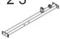 Main Base Tube1PC Main Base Tube1PC | 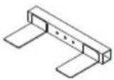 Front Base Tube1PC Front Base Tube1PC | 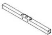 Rear Base Tube1PC Rear Base Tube1PC | 4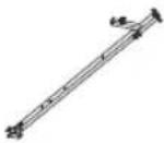 Main Support Tube1PC Main Support Tube1PC | 5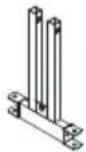 Press Bar1PC Press Bar1PC |
6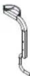 Left Butterfly Arm1PC Left Butterfly Arm1PC | 7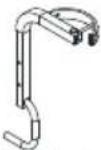 Right Butterfly Arm1PC Right Butterfly Arm1PC | 8 9 10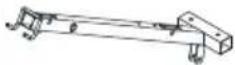 Upper Cross Beam1PC Upper Cross Beam1PC | 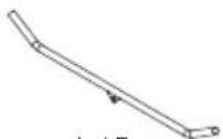 Lat Bar1PC Lat Bar1PC |  M10 Nut2PCS M10 Nut2PCS |
11 12 13 14  Leg Extension Tube1PC Leg Extension Tube1PC | 15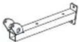 Seat Support Tube1PC Seat Support Tube1PC | 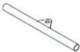 Lower Bar1PC Lower Bar1PC | 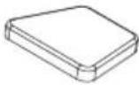 Seat Cushion1PC Seat Cushion1PC | 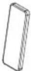 Backrest Cushion1PC Backrest Cushion1PC |
16 17 18 19 20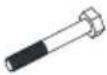 M8X60mm Hex Bolt4PCS M8X60mm Hex Bolt4PCS | 20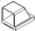 45mm Square End Cap2pcs 45mm Square End Cap2pcs | 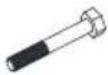 M8X65mm Hex Bolt10PCS M8X65mm Hex Bolt10PCS | [TT20]M8 Washer32PCS | [880S]M8 Nylon Nut12PCS |
21 22 23 24 25 38mm Square End Cap1PC 38mm Square End Cap1PC | 25 38mm Square End Plug4PCS 38mm Square End Plug4PCS | 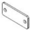 Plate3PCS Plate3PCS | 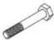 M10X65mm Hex Bolt6PCS M10X65mm Hex Bolt6PCS |  M10X45mm Hex Bolt8PCS M10X45mm Hex Bolt8PCS |
26 27 28 29 30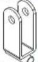 Pulley Bracket2PCS Pulley Bracket2PCS | 30 Pulley12PCS Pulley12PCS |  45mm Square End Plug6PCS 45mm Square End Plug6PCS | 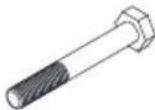 M12X140mm Hex Bolt1PC M12X140mm Hex Bolt1PC | Pre-assembled Oil Bushing6PCS Oil Bushing6PCS |
31 32 33 34 35 M12 Nylon Nut3PCS M12 Nylon Nut3PCS | 35 Pulley Bushing8PCS Pulley Bushing8PCS | 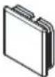 50mm Square End Plug2PCS 50mm Square End Plug2PCS |  M10X25mm Hex Bolt4PCS M10X25mm Hex Bolt4PCS |  M10 Washer38PCS M10 Washer38PCS |
36 37 38 39 40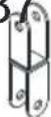 Reverse U1PC Reverse U1PC | 40[zckw]Pulley U1PC | 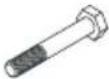 M10X70mm Hex Bolt1PC M10X70mm Hex Bolt1PC | [TSWG]Handle Grip4PCS | [ZYW]Pothook4PCS |
PARTS LIST DRAWING
41 42 43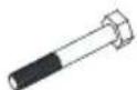 M8X55mm Hex Bolt4PCS M8X55mm Hex Bolt4PCS | 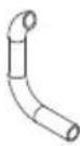 Handle Foam2PCS Handle Foam2PCS |  25mm Round End Plug6PCS 25mm Round End Plug6PCS | 44 45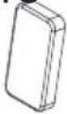 Arm Cushion2PCS Arm Cushion2PCS | 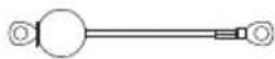 Lower Cable1PC Lower Cable1PC |
46 30mm Square End Plug2PCS 30mm Square End Plug2PCS | 47 Bumper2PCS Bumper2PCS | 48 49 50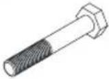 M12X75mm Hex Bolt2PCS M12X75mm Hex Bolt2PCS | 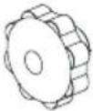 Plum Blossom Nut1PC Plum Blossom Nut1PC |  M8X40mm Hex Bolt2PCS M8X40mm Hex Bolt2PCS |
51 52 53 54  Bolt Cap (M12)4PCS Bolt Cap (M12)4PCS | 55 Bolt Cap (M10)2PCS Bolt Cap (M10)2PCS | 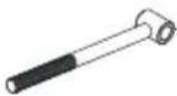 Tobacco-pipe1PC Tobacco-pipe1PC | 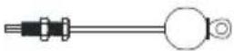 Upper Cable1PC Upper Cable1PC | 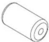 Leg Foam Roller4PCS Leg Foam Roller4PCS |
56 57 58 59 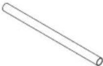 Foam Tube2PCS Foam Tube2PCS | 60 Butterfly Cable1PC Butterfly Cable1PC |  M10 Nylon Nut17PCS M10 Nylon Nut17PCS | 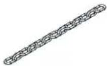 Chain2PCS Chain2PCS | 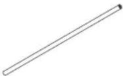 Weight Guide Tube2PCS Weight Guide Tube2PCS |
61 62 63 64 65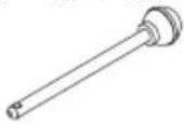 Weight Selector Pin1PC Weight Selector Pin1PC | 65 Rubber Ring2PCS Rubber Ring2PCS | 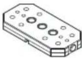 Weight Plate9PCS Weight Plate9PCS | 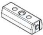 Top Weight Plate1PC Top Weight Plate1PC | 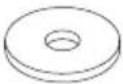 Plastic Washer1PC Plastic Washer1PC |
66 67 68 69 70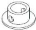 Selector Shaft Bushing1PC Selector Shaft Bushing1PC | 70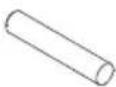 Selector Shaft Pin1PC Selector Shaft Pin1PC | 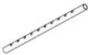 Selector Shaft1PC Selector Shaft1PC |  M12 Washer6PCS M12 Washer6PCS |  M10X35mm Hex Bolt2PCS M10X35mm Hex Bolt2PCS |
71 72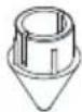 Select Shaft End Cap1PC Select Shaft End Cap1PC |  Washer(φ30Xφ10)1PC Washer(φ30Xφ10)1PC | |||
ASSEMBLY INSTRUCTIONS
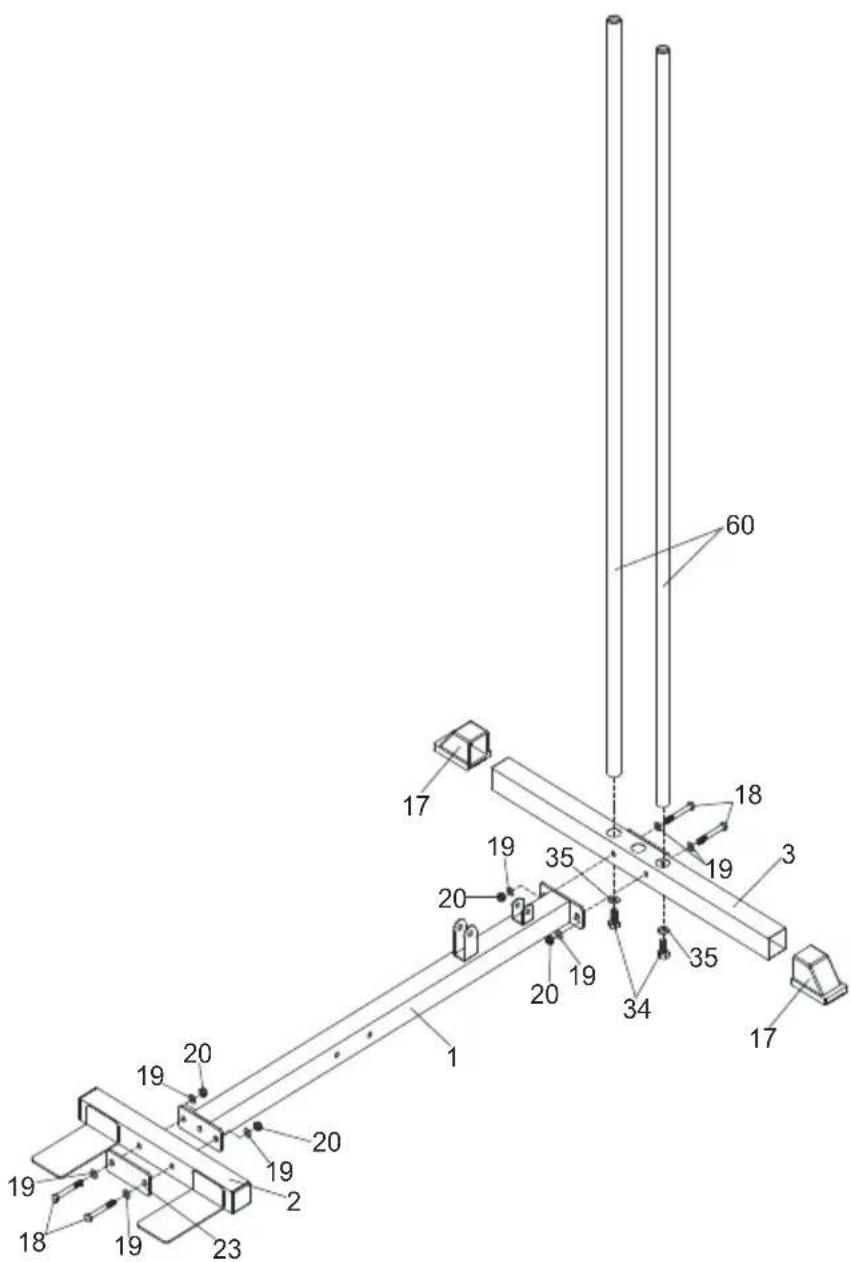
STEP 1
- Tap two 45mm Square End Caps (17) to the Rear Base Tube (3).
- Remove two M10X25mm Hex Bolts (34) and two M10 Washers (35) from two Weight Guide Tubes (60).
- Insert the Weight Guide Tube (60) into the Rear Base Tube (3), using two M10X25mm Hex Bolts (34) and two M10 Washers (35).
- Attach the Main Base Tube (1) to the Rear Base Tube (3), using two M8X65mm Hex Bolts (18), four M8 Washers (19) and two M8 Nylon Nuts (20).
- Attach the Front Base Tube (2) and the Plate (23) to the Main Base Tube (1), using two M8X65mm Hex Bolts (18), four M8 Washers (19) and two M8 Nylon Nuts (20).
ASSEMBLY INSTRUCTIONS
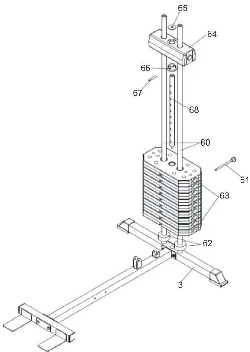
STEP 2
- Slide two Rubber Rings (62) onto the Weight Guide Tube (60).
- Slide nine Weight Plates (63) down two Weight Guide Tubes (60).
- Slide the Selector Shaft Bushing (66) down the Selector Shaft (68) at First hole fix with the Selector Shaft Pin (67).
- Insert the Selector Shaft (68) into hole of the Weight Plate (63).
- Slide the Top Weight Plate (64) down the Selector Shaft (68). Insert the Weight Selector Pin (61) into hole of desired Weight.
- Put the Plastic Washer (65) on the Top Weight Plate (64).
ASSEMBLY INSTRUCTIONS
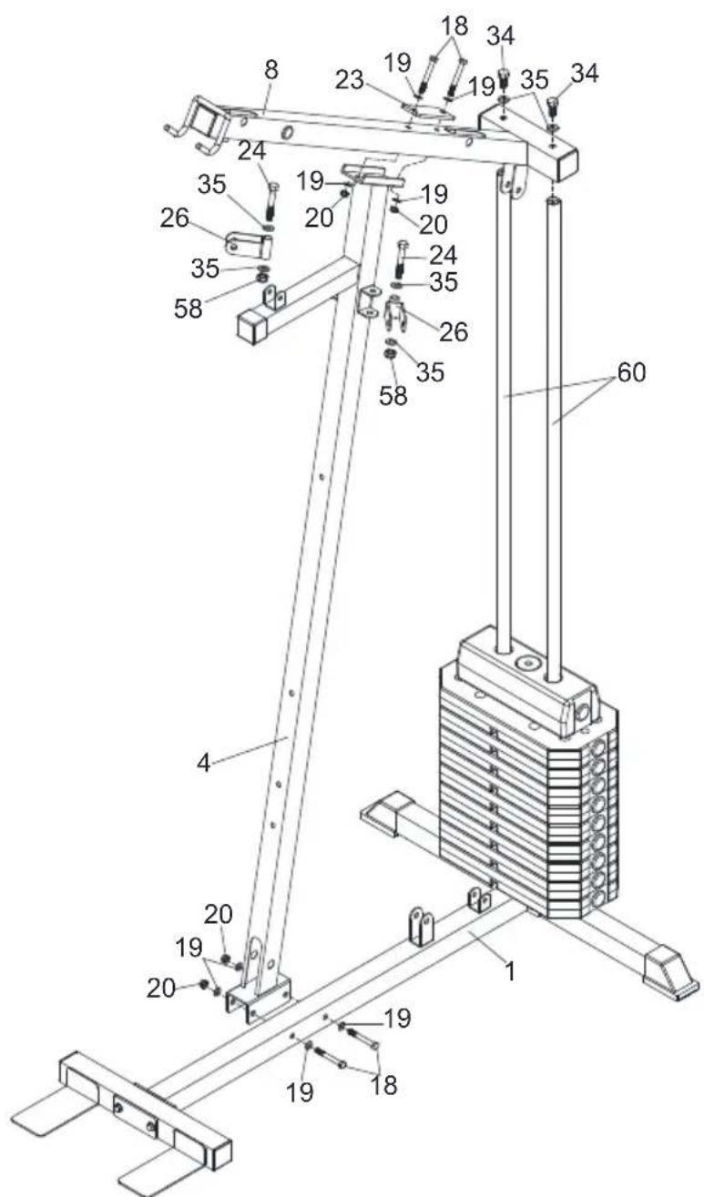
STEP 3
- Attach the Main Support Tube (4) to the Main Base Tube (1), using two M8X65mm Hex Bolts (18), four M8 Washers (19) and two M8 Nylon Nuts (20).
- Remove two M10X25mm Hex Bolts (34) and two M10 Washers (35) from two Weight Guide Tube (60).
- Attach the Upper Cross Beam (8) to the Weight Guide Tube (60), using two M10X25mm Hex Bolts (34) and two M10 Washers (35).
- Attach the Upper Cross Beam (8) and the Plate (23) to the Main Support Tube (4), using two M8X65mm Hex Bolts (18), four M8 Washers (19) and two M8 Nylon Nuts (20).
- Attach two Pulley Brackets (26) to the Main Support Tube (4), using two M10X65mm Hex Bolts (24), four M10 Washers (35) and two M10 Nylon Nuts (58).
ASSEMBLY INSTRUCTIONS
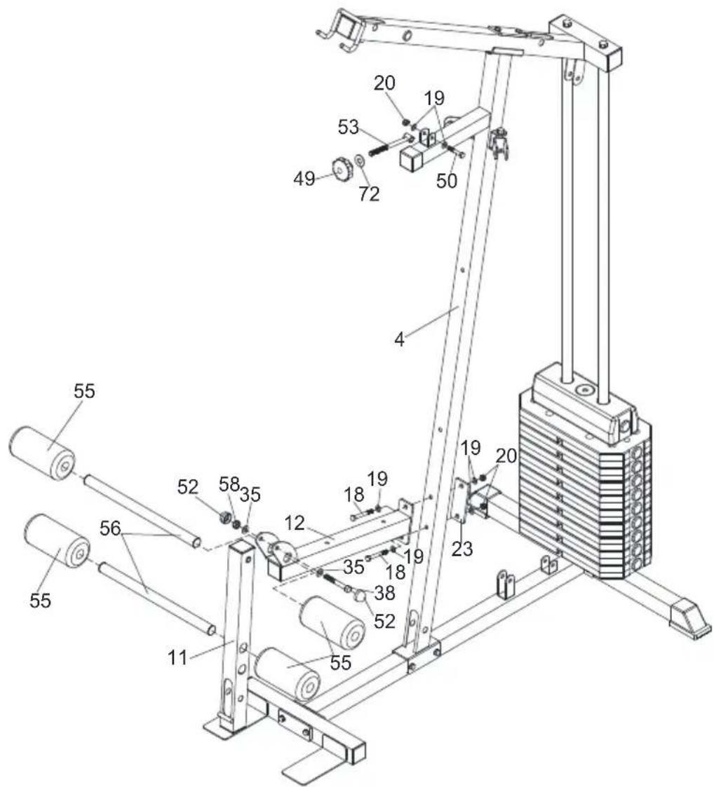
STEP 4
- Attach the Seat Support Tube (12) and the Plate (23) to the Main Support Tube (4), using two M8X65mm Hex Bolts (18), four M8 Washers (19) and two M8 Nylon Nuts (20).
- Attach the Leg Extension Tube (11) to the Seat Support Tube (12), using one M10X70mm Hex Bolt (38), two M10 Washers (35), one M10 Nylon Nut (58) and two Bolt Caps (M10) (52).
- Insert two Foam Tubes (56) into the Leg Extension Tube (11) and the Seat Support Tube (12), then slide four Leg Foam Rollers (55) onto two Foam Tubes (56).
- Attach the Tobacco-pipe (53) to the Main Support Tube (4), using one M8X40mm Hex Bolt (50), two M8 Washers (19) and one M8 Nylon Nut (20).
- Slide one Washer ( 30X 10) (72) and one Plum Blossom Nut (49) onto the Tobacco-pipe (53).
ASSEMBLY INSTRUCTIONS
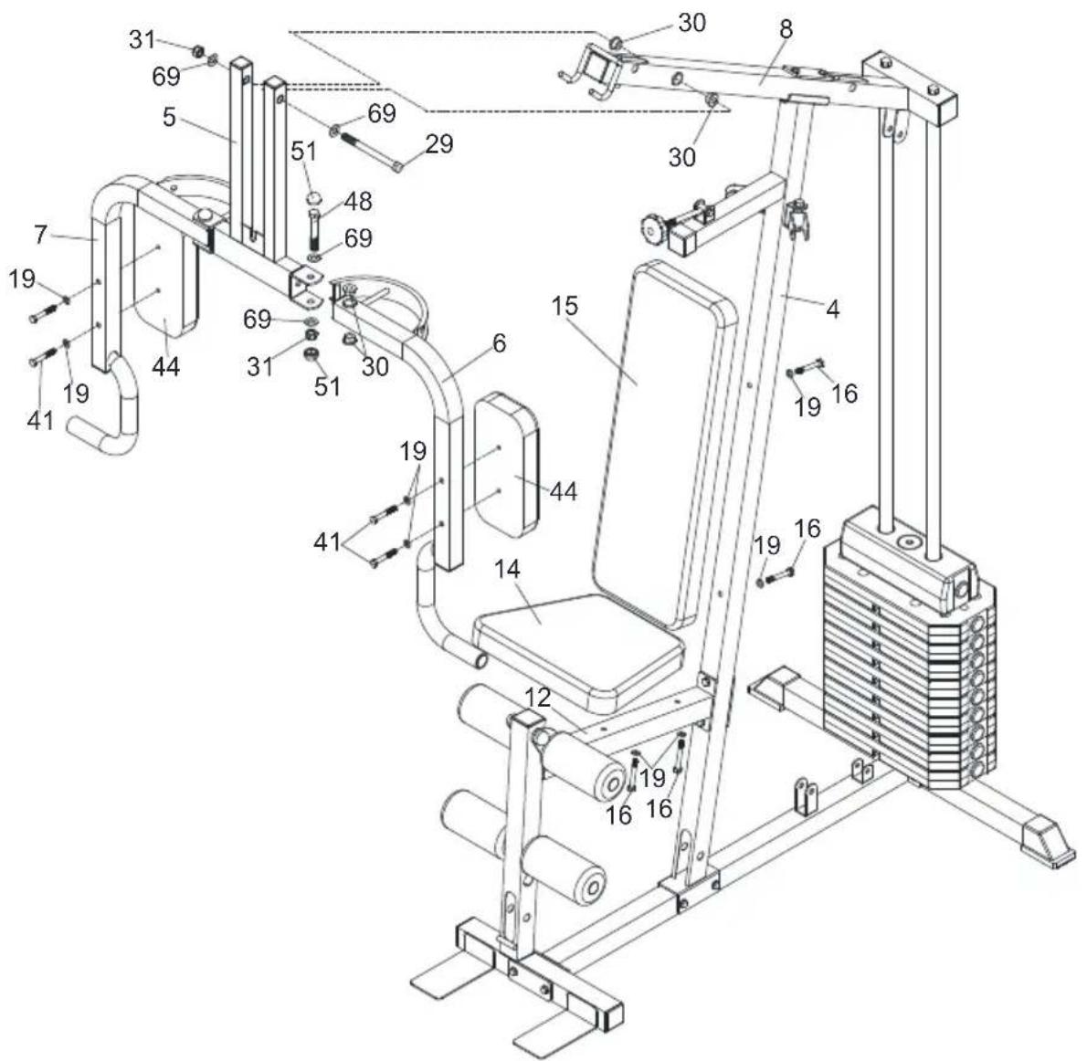
STEP 5
Note: Oil Bushings (30) have been Pre-assembled into the Upper Cross Beam (8) and the Butterfly Arm (6&7).
- Attach the Press Bar (5) to the Upper Cross Beam (8), using one M12X140mm Hex Bolt (29), two M12 Washers (69) and one M12 Nylon Nut (31).
- Attach the Left Butterfly Arm (6) and the Right Butterfly Arm (7) to the Press Bar (5), using two M12X75mm Hex Bolts (48), four M12 Washers (69), two M12 Nylon Nuts (31) and four Bolt Caps (M12) (51).
- Attach two Arm Cushions (44) to the Left Butterfly Arm (6) and the Right Butterfly Arm (7), using four M8X55mm Hex Bolts (41) and four M8 Washers (19).
- Attach the Seat Cushion (14) to the Seat Support Tube (12), using two M8X60mm Hex Bolts (16) and two M8 Washers (19).
- Attach the Backrest Cushion (15) to the Main Support Tube (4), using two M8X60mm Hex Bolts (16) and two M8 Washers (19).
ASSEMBLY INSTRUCTIONS
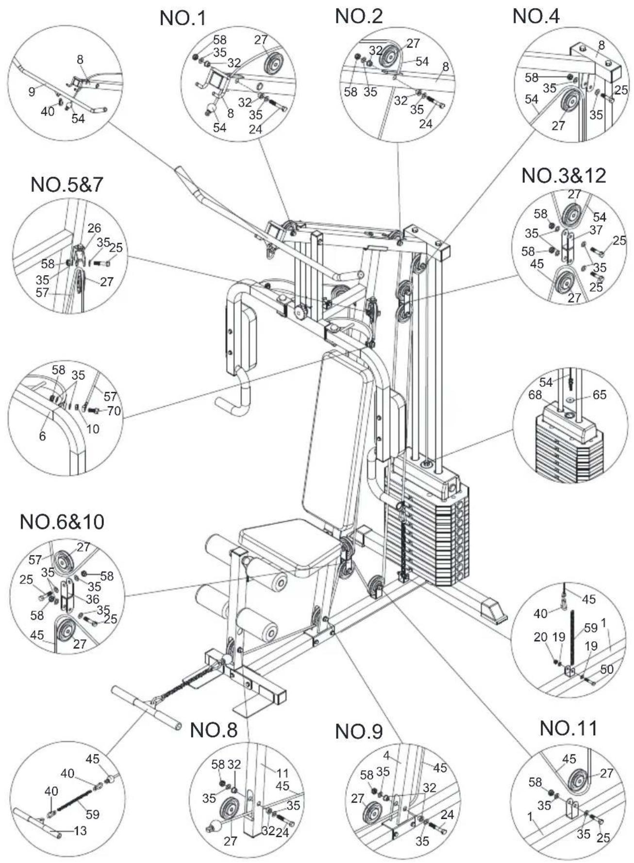
ASSEMBLY INSTRUCTIONS
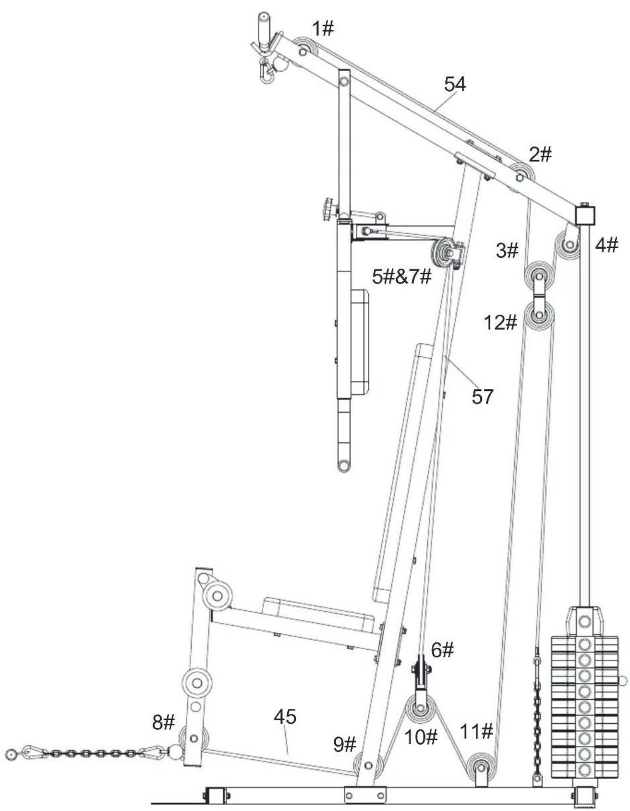
ASSEMBLY INSTRUCTIONS
STEP 6
-
Assembly the Upper Cable (54)
a). With the Upper Cable (54) in groove of Pulley (27), thread the Upper Cable (54) through the Upper Cross Beam (8).
b). Install Pulley NO.1 (27) and two Pulley Bushings (32) to the Upper Cross Beam (8), using one M10X65mm Hex Bolt (24), two M10 Washers (35) and one M10 Nylon Nut (58).
c). Install Pulley NO.2 (27) and two Pulley Bushings (32) to the Upper Cross Beam (8), using one M10X65mm Hex Bolt (24), two M10 Washers (35) and one M10 Nylon Nut (58).
d). Install Pulley NO.4 (27) to the Upper Cross Beam (8), using one M10X45mm Hex Bolt (25), two M10 Washers (35) and one M10 Nylon Nut (58).
e). Attach the bolt end of Upper Cable (54) to the Selector Shaft (68) with a Plastic Washer (65).
f). Install Pulley NO.3 (27) to the Pulley U (37), using one M10X45mm Hex Bolt (25), two M10 Washers (35) and one M10 Nylon Nut (58).
g). Attach the Lat Bar (9) to the other end of Upper Cable (54) using one Pothook (40). -
Assembly the Butterfly Cable (57)
a). Attach both ends of Butterfly Cable (57) to the Left and Right Butterfly Arm (6&7), using two M10X35mm Hex Bolts (70), two M10 Nuts (10), four M10 Washers (35) and two M10 Nylon Nuts (58).
b). Install Pulley NO.5&7 (27) to the Pulley Bracket (26), using two M10X45 mm Hex Bolts (25), four M10 Washers (35) and two M10 Nylon Nuts (58).
c). Install Pulley NO.6 (27) to the Reverse U (36), using one M10X45mm Hex Bolt (25), two M10 Washers (35) and one M10 Nylon Nut (58).
- Assembly the Lower Cable (45)
a). With the Lower Cable (45) in groove of Pulley (27) through the Leg Extension Tube (11).
b). Install Pulley NO.8 (27) and two Pulley Bushings (32) to the Leg Extension Tube (11), using one M10X65mm Hex Bolt (24), two M10 Washers (35) and one M10 Nylon Nut (58).
c). Install Pulley NO.9 (27) and two Pulley Bushings (32) to the Main Support Tube (4), using one M10X65mm Hex Bolt (24), two M10 Washers (35) and one M10 Nylon Nut (58).
d). Install Pulley NO.10 (27) to the Reverse U (36), using one M10X45mm Hex Bolt (25), two M10 Washers (35) and one M10 Nylon Nut (58).
e). Install Pulley NO.11 (27) to the Main Base Tube (1), using one M10X45mm Hex Bolt (25), two M10 Washers (35) and one M10 Nylon Nut (58).
f). Install Pulley NO.12 (27) to the Pulley U (37), using one M10X45mm Hex Bolt (25), two M10 Washers (35) and one M10 Nylon Nut (58).
g). Attach the end of Lower Cable (45) to the Main Base Tube (1), using one M8X40mm Hex Bolt (50), two M8 Washers (19), one M8 Nylon Nut (20), one Pothook (40) and one Chain (59).
h). Attach the Lower Bar (13) to the other end of Lower Cable (45), using two Pothooks (40) and one Chain (59).
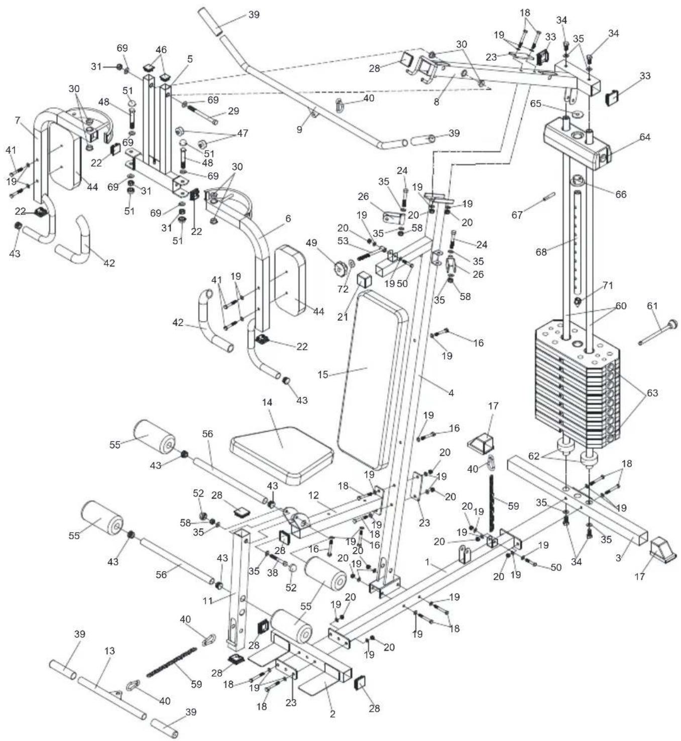
EXPLODED DRAWING
Welcome to visit our website and purchase our quality products!
Your suggestions and comments for COSTWAY are really important to us!
We sincerely solicit you to go back to our shop and leave a good rating in just a simple click. It would be quite encouraging if you could kindly do so like below:
★★★★★ Great products so far
February 24, 2019
Great products so far. Fast delivery, easy setup, and working without any issues.
With your inspiring rating, COSTWAY will be more consistent to offer you EASY SHOPPING EXPERIENCE, GOOD PRODUCTS and EFFICIENT SERVICE!
US office: Fontana, California
UK office: Ipswich

* Reward Points
* Exclusive Customer Service
* Personalized Recommendations
* Permanent Shopping Cart
* Order History
5 Star Rating

natural_image
Five black five-pointed stars arranged horizontally on white background (no text or symbols)We would like to extend our heartfelt thanks to all of our customers for taking time to assemble this product and giving us valuable feedbacks.


Brand : COSTWAY
Model : SP36555
Category : Fitness Equipment