DSP ULTRA S - Processor Helix - Free user manual and instructions
Find the device manual for free DSP ULTRA S Helix in PDF.


| Product Type | Digital Signal Processor (DSP) |
| Brand | Helix |
| Model | DSP ULTRA S |
| Dimensions (H x W x D) | 40 x 177 x 170 mm / 1.58 x 6.97 x 6.69 in |
| Weight | Not specified (estimated approx. 0.5 kg) |
| Operating Voltage | 9.6 - 17 Volts (min. 6V for 5 sec) |
| Power Consumption | DC 12 V = 1.1 A max, 550 mA typical |
| Analog Inputs | 8 x RCA / Cinch, 8 x Highlevel speaker input |
| Digital Inputs | 1 x Optical SPDIF (12-96 kHz), 1 x Coax SPDIF (12-192 kHz) |
| Analog Outputs | 12 x RCA / Cinch |
| Input Sensitivity (RCA) | 1 - 8 Volts (adjustable) |
| Input Sensitivity (Highlevel) | 4 - 32 Volts (adjustable) |
| Output Voltage | 8 Volts max |
| Frequency Response | 10 Hz - 44,000 Hz |
| DSP Resolution | 64 Bit |
| DSP Power | 2 x 295 MHz (2.4 billion MAC operations/sec) |
| Sampling Rate | 96 kHz |
| Signal-to-Noise Ratio (Analog) | 111 dB (A-weighted) |
| Signal-to-Noise Ratio (Digital) | 117 dB (A-weighted) |
| THD+N (Analog) | < 0.0008% |
| THD+N (Digital) | < 0.0004% |
| IM Distortion (Analog) | < 0.003% |
| IM Distortion (Digital) | < 0.0015% |
| Crosstalk | > 90 dB |
| Operating Temperature Range | -40°C to +70°C |
| Additional Features | HEC slot, Ground lift switch, Smart Control Port, 32 Bit CoProcessor, ADEP.3 circuit, Auto Remote switch, Virtual Channel Processing, 10 memory presets |
| Warranty | Statutory regulations; defects from overload or improper handling excluded |
Frequently Asked Questions - DSP ULTRA S Helix
User questions about DSP ULTRA S Helix
0 question about this device. Answer the ones you know or ask your own.
Ask a new question about this device
Download the instructions for your Processor in PDF format for free! Find your manual DSP ULTRA S - Helix and take your electronic device back in hand. On this page are published all the documents necessary for the use of your device. DSP ULTRA S by Helix.
USER MANUAL DSP ULTRA S Helix
Kanal C = Hinten links
Line Input / Cinch: 1 - 8 Volt
natural_image
Close-up of a computer motherboard with a highlighted component (no readable text or symbols)natural_image
Diagram of a SCP-to-Control Input Adapter connector with two pins (no text or symbols on the diagram itself)5. Masseschalter
![Subwoofer 1 100.0 % Subwoofer 2 100.0 % Subwoofer 1 Output K [SubRC] Subwoofer 2 Output L [SubRC]](/content/2026/05/907442/images/15030a513ff2de46929e7e7a12494e73999e401d76c2b77ab610834535f078af.jpg)
Turn On & Off Delay
Remote Output Configuration
natural_image
Close-up of a computer motherboard with visible circuit components and connectors (no readable text or symbols)natural_image
Close-up of electronic circuit board with multiple LED connectors and a green checkmark highlighting a specific component (no readable text or symbols)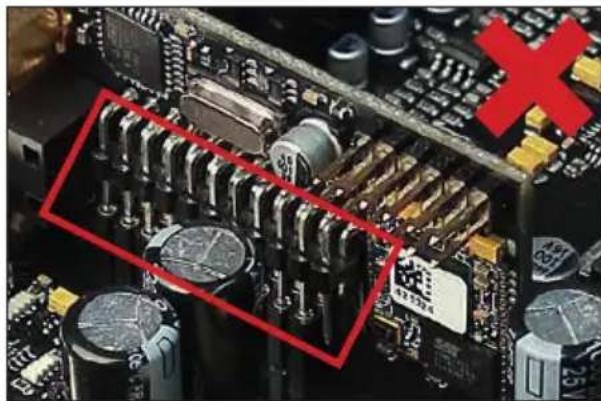
natural_image
Close-up of a computer motherboard with visible capacitors and components, marked by a red X (no text or symbols)Congratulations on your purchase of this innovative and high-qual ity HELIX product.
Thanks to more than 30 years of experience in research and development of audio products the HELIX DSP ULTRA S sets new standards in the range of digital signal processors.
We wish you many hours of enjoyment with your new HELIX DSP ULTRA S.
Yours, AUDIOTEC FISCHER
General instructions
General installation instructions for HELIX components
To prevent damage to the unit and possible injury, read this manual carefully and follow all installation instructions. This product has been checked for proper function prior to shipping and is guaranteed against manufacturing defects.
Before starting your installation, disconnect the battery's negative terminal to prevent damage to the unit, fire and / or risk of injury. For a proper performance and to ensure full warranty coverage, we strongly recommend to get this product installed by an authorized HELIX dealer.
Install your HELIX DSP ULTRA S in a dry location with sufficient air circulation for proper cooling of the equipment. The signal processor should be secured to a solid mounting surface using proper mounting hardware. Before mounting, carefully examine the area around and behind the proposed installation location to insure that there are no electrical cables or components, hydraulic brake lines or any part of the fuel tank located behind the mounting surface. Failure to do so may result in unpredictable damage to these components and possible costly repairs to the vehicle.
General instruction for connecting the HELIX DSP ULTRA S signal processor
The HELIX DSP ULTRA S signal processor may only be installed in vehicles which have a 12 Volts negative terminal connected to the chassis ground. Any other system could cause damage to the signal processor and the electrical system of the vehicle.
The positive cable from the battery for the entire sound system should be provided with a main fuse -at a distance of max. 30 cm from the battery. The value of the fuse is calculated from the maximum total current draw of the car audio system.
Use only the provided connectors for connection of the HELIX DSP ULTRA S. The use of other connectors or cables can result in damage of the signal processor, the head unit / radio or the connected amplifiers / loudspeakers!
Prior to installation, plan the wire routing to avoid any possible damage to the wire harness. All cabling should be protected against possible crushing or pinching hazards. Also avoid routing cables close to potential noise sources such as electric motors, high power accessories and other vehicle harnesses.
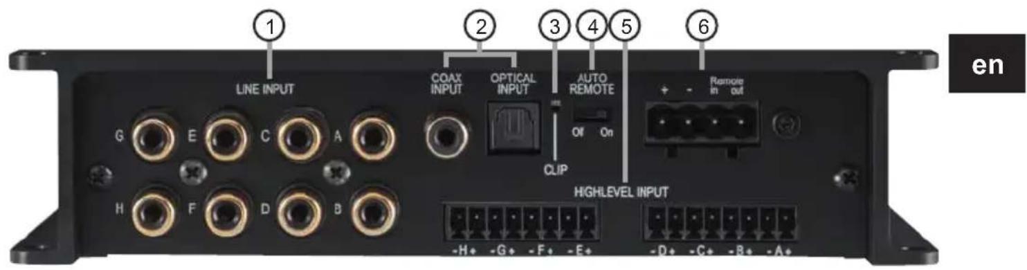
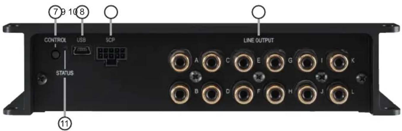
① Lowlevel line inputs
Page 20, point 2
② Digital inputs (Coaxial & Optical)
Page 21, point4
③ Clipping LED
Page 24, point 1
④ Auto Remote switch
Page 21, point 5
⑤ Highlevel speaker inputs
Page 21, point 3
⑥ Power & Remote connector
Page 21, point 6
7 Control pushbutton
Page 24, point 2
⑧ USB input
Page 22, point 7
⑨ SCP (Smart Control Port)
Page 25, point 4
10 Line outputs
Page 24, point 11
11 Status LED
Page 25, point 3
Configure the HELIX DSP ULTRA S as follows
Caution: Carrying out the following steps will require special tools and technical knowledge. In order to avoid connection mistakes and / or damage, ask your dealer for assistance if you have any questions and follow all instructions in this manual (see page 18). It is recommended that this unit will be installed by an authorized HELIX dealer.
1. Configuration of the "Load Jumper" for the highlevel input
Before changing the configuration of the "Load Jumper", please note the following information. This adjustment is only necessary when connecting devices from the following categories to the highlevel inputs:
- Premium sound system amplifiers with an output power of more than 50 W RMS
For standard applications, such as connecting:
- Factory radios
- Aftermarket radios via RCA / Cinch cables
this adjustment is not required. In such cases, you can proceed directly to point 2, "Connecting the pre-amplifier inputs".
To change the setting of the "Load Jumper", follow these steps:
a. Open the signal processor
Remove the side panel with the line outputs by loosening the five Phillips screws and pulling the bottom plate out of the heat sink to the side.
b. Determine the output voltage of the signal source
We recommend measuring the maximum output voltage using an appropriate measuring device or contacting your authorized HELIX dealer. If you are unsure, we recommend removing the "Load Jumper" to avoid possible damage to the device.
c. Removing the "Load jumper" / leaving it plugged in
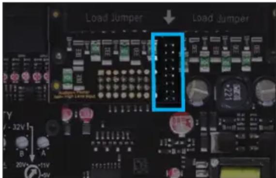
To remove the "Load Jumper", simply pull the jumper, see figure 2.
Overview "Load Jumper" configuration:
"Load Jumper" inserted (factory setting / see fig. 1):
Value range: Highlevel 4 - 11 Volts
"Load Jumper" removed (see fig.2):
Value range: Highlevel 12 - 32 Volts
Figure 1:
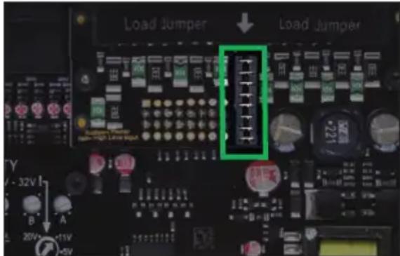
Figure 2:
d. Reassemble the signal processor
2. Connecting the pre-amplifier inputs
These eight lowlevel line inputs can be connected to signal sources such as head units / radios using appropriate cables. Each input can be assigned to any output using the DSP PC-Tool software. Input sensitivity is factory-set to 4 Volts for all channels. But it is possible to optimally adapt the input sensitivity to the signal source inside the device (see page 22, point 8).
The automatic turn-on circuit does not work
when using the pre-amplifier inputs. In this case the remote input (see page 19, point 6) has to be connected to activate the HELIX DSP ULTRA S.
3. Connecting the highlevel speaker inputs
The eight highlevel loudspeaker inputs can be connected directly to the loudspeaker outputs of an OEM, aftermarket radio or factory installed amplifier using appropriate cables (loudspeaker cables with 1 mm ^2 / AWG 18 max.).
We recommend the following channel assignment if a common car radio will be connected to the signal processor:
Channel A = Front left
Channel B = Front right
Channel C = Rear left
Channel D = Rear right
Actually it is not mandatory to use all high-level loudspeaker inputs. If only two channels will be connected we recommend to use the channels A and B. Make sure that the polarity is correct. If one or more connections have reversed polarity it may affect the performance of the signal processor. When using this input, the remote input does not need to be connected as the signal processor will automatically turn on once a loudspeaker signal is received. Input sensitivity is factory-set to 11 Volts for all channels. It is possible to optimally adapt the input sensitivity to the signal source inside the device (see page 22, point 8).
Attention: Solely use the pluggable screw-terminals for connecting the highlevel input which are included in delivery!
4. Connecting a digital signal source
If you have a signal source with a coaxial or optical digi tal output you can connect it to the signal processor using the appropriate input. The sampling rate must be between 12 and 96 kHz for the optical input and 12 - 192 kHz for the coaxial input (Coax Input). The input signal is automatically adapted to the internal sample rate.
In standard configuration the optical input is activated as well as the manual activation via an optional remote control is configured.
Alternatively you can activate the automatic turn-on feature in the DCM menu of the DSP PC-Tool software.
The automatic turn-on circuit does not work when a digital input is used. Therefore it is mandatory to connect the remote input (see page 19, point 6).
Important: The signal of a digital audio source normally does not contain any information about the volume level. Keep in mind that this will lead to full level on the outputs of the HELIX DSP ULTRA S and your connected amplifiers. This may cause severe damage to your speakers. We strongly recommend to use an optional remote control for adjusting the volume level of the digital signal inputs!
Note: The HELIX DSP ULTRA S can only handle uncompressed digital stereo signals in PCM format with a sample rate between 12 kHz and 96 kHz / 192 kHz and no MP3- or Dolby-coded digital audio stream!
5. Configuration of the remote input
The DSP ULTRA S will be turned on automatically if the highlevel input is used or if a signal is applied to the remote input terminal. The auto remote switch (page 19, point 4) allows to deactivate the automatic turn-on feature of the highlevel inputs. The feature should be deactivated if there are e.g. noises while switching on / off the signal processor.
On: Activation via highlevel speaker input is enabled (by default).
Off: Activation via highlevel speaker input is disabled.
Note: If the automatic turn-on function is deactivated it is mandatory to use the remote input terminal to power up the signal processor! The highlevel signal will be ignored in this case.
6. Connection to power supply & remote
Make sure to disconnect the battery before installing the HELIX DSP ULTRA S!
Solely use the included screw-type terminal to connect the HELIX DSP ULTRA S to a power supply. Make sure of correct polarity.
±: Connector for the +12 V power cable. The positive wire has to be connected to the battery's positive post or a power distribution block. Though the current draw of the HELIX
DSP ULTRA S is rather low (approx. 550 mA) we recommend a minimum wire gauge of 1 mm^2 / AWG18 .
=: Connector for the ground cable. The ground wire must be connected to the vehicle chassis at a non-insulated point. The cable should have the same gauge as the +12 V wire. Inadequate grounding causes audible interference and malfunctions.
Remote in: The remote input is used to switch on the DSP ULTRA S if the pre-amplifier or digital inputs are used. Additionally, this input must be assigned, if the signal source which is connected to the Highlevel Input is not activating the "automatic turn-on" function or if the signal processor shall only be activated / de-activated via a remote signal. The remote wire should be connected to the remote output / automatic antenna (aerial positive) output of the head unit / car radio. This is only activated if the head unit is switched on. Thus the signal processor is switched on and off together with the head unit.
We do not recommend controlling the remote input via the ignition switch to avoid pop noise during turn on / off.
Note: This input does not need to be assigned if the Highlevel Input is used. To deactivate the "automatic turn-on" function read the description on page 21, point 5 "Configuration of the remote input".
Remote out: The remote output is used for turning on / off amplifiers that are connected to the line outputs of the HELIX DSP ULTRA S. Therefore connect the remote output of the DSP to the remote inputs of your amplifiers to switch them on and off via the DSP without interfering signals. The remote output is activated automatically as soon as the booting process of the DSP is completed. Additionally this output will be turned off during the “Power Save Mode” or a software update process.
IMPORTANT: Never use a different signal than the remote output of the DSP to activate connected amplifiers!
7. Connecting the PC & first start-up
The USB input enables the connection of the DSP ULTRA S to a personal computer and its free configuration with our DSP PC-Tool software using the provided USB cable.
Please note: It is not possible to connect any USB storage devices.
Prior to connecting the signal processor to your PC visit our website and download the latest version of the DSP PC-Tool software.
We strongly recommend to carefully read the DSP PC-Tool knowledge base before using the software for the first time in order to avoid any complications and failures.
Important: Make sure that the signal processor is not connected to your computer before the software and USB driver are installed!
In the following the most important steps how to connect and the first start-up are described:
-
Download the latest version of the DSP PC-Tool software (available on our website www.audiotec-fischer.com) and install it on your computer.
-
Connect the signal processor to your computer using the USB cable that is included in delivery. If you have to bridge longer distances please use an active USB extension cable with integrated repeater.
-
First turn on the signal processor and then start the software. The operating software will be updated automatically to the latest version if it is not up-to-date.
8. Adjustment of the input sensitivity of the analog signal inputs
ATTENTION: It is mandatory to properly adapt the input sensitivity of the DSP ULTRA S to the signal source in order to achieve the best possible signal quality and to avoid damage to the signal processor. When using the highlevel input as a signal input, it is essential to configure its “Load Jumper” first (see page 20, point 1).
To change the input sensitivity, the device must be opened as described on page 20, point 1. Then you have access to the eight controls that allow adjusting each channel individually (see marking in the following picture).
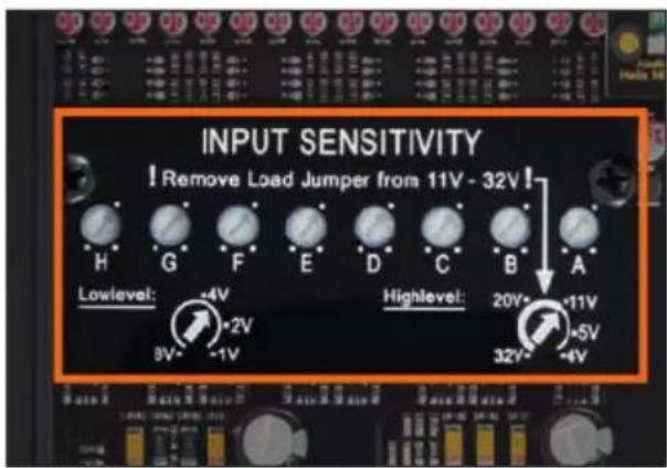
The setting of the controls affects both the lowlevel and the highlevel inputs!
The gain control ranges are:
Highlevel: 4 - 32 Volts
Line Input / RCA / Cinch: 1 - 8 Volts
Input sensitivity is factory set to 11 Volts (high-level) and 3 Volts (Line Input / RCA / Cinch).
This is definitely the best setting in most applications.
If the signal source provides a lower output voltage, the input sensitivity can be increased continuously. If your signal source delivers a higher output voltage – for example, if a factory-installed amplifier serves as signal source – the input sensitivity must be lowered and the correct configuration of the “Load Jumper” must be checked (page 20, point 1).
If you are not sure regarding the signal sources output voltage, please contact your HELIX specialist dealer.
The Clipping LED (see page 19, point 3) serves as monitoring tool.
Proceed as follows to adjust the input sensitivity (The adjustment will be easier when you connect and adjust one input channel after the other):
-
Don't connect any amplifiers to the outputs of the HELIX DSP ULTRA S during this setup.
-
Turn on the signal processor
-
Adjust the volume of your radio to approx. 90 % of the max. volume and playback
an appropriate test tone, e.g. the special and unique "Input Gain Setup" signal from the test tones folder of the DSP PC-Tool (0 dB).
- If the Clipping LED already lights up, you have to reduce the input sensitivity via the respective control until the LED turns off.
- Increase the input sensitivity by turning the control clockwise until the LED lights up. Now turn the control counterclockwise until the Clipping LED turns off again.
- Repeat this process for each signal input used.
IMPORTANT: It is mandatory to configure the "Load Jumper" inside the device before the input sensitivity of a channel is set to values > 11 Volts (see page 20, point 1).
Disregarding this may cause severe damage to the processor.
9. Configuration of the DSP
The general DSP settings should be conducted with the DSP PC-Tool software before using the signal processor for the first time.
Now you are able to configure your DSP ULTRA S with our intuitive DSP PC-Tool software. Useful hints for the correct setting can be found in our knowledge base at www.audiotec-fischer.com.
Caution: We highly recommend to set the volume of your car radio to minimum position during first start-up. Additionally no devices should be connected to the signal processor. Especially if the DSP ULTRA S will be used in fully active applications, a wrong setup can destroy your speakers right away.
10. Analyzing the input signal
Check the input signal for factory-set equalizing and all-pass filters using the Input Signal Analyzer (ISA) of the DSP PC-Tool software. Information about the ISA can be found in the extensive Knowledge Base on our website www.audiotec-fischer.com.
Caution: We highly recommend to set the volume of your signal source to minimum position during first start-up. Additionally no devices should be connected to the signal processor until general settings in the DSP
PC-Tool software have been made. Especially if the DSP ULTRA S will be used in fully active applications, a wrong setup can destroy your speakers right away.
11. Connecting the Line Outputs
The 12 pre-amplifier outputs (Line Output) can now be connected to the pre-amplifier / lowlevel / RCA inputs of the external amplifiers using appropriate cables (RCA / Cinch cables). The outputs provide a maximum output voltage of 8 Volts. Please make sure that you always turn on / off external amplifiers using the remote output of the DSP ULTRA S in order to avoid interfering noises.
12. Sound tuning
Now you can create your sound setup. Information about sound tuning can be found in our extensive knowledge base at www.audiotec-fischer.com or contact your local HELIX dealer.
13. Optional: Adjustment of the ground connection
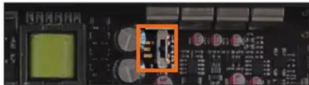
The signal ground of the HELIX DSP ULTRA S is galvanically decoupled from the power ground. In many cars this setup is the best way to avoid alternator noise. Nevertheless, there are use cases where it will be necessary to tie signal and power ground together directly or to connect them via a 200 Ohms resistor softly. To get access to the ground lift switch and change the ground setting the device has to be opened as described on page 20, point 1.
natural_image
Close-up of an electronic circuit board with a highlighted component (no readable text or symbols)- Center position: input and output ground separated.
- Left position: input and output ground tied together.
- Right position: input and output ground connected via 200 Ohms resistor.
Additional functions
1. Clipping LED
Normally the Clipping LED is off and only lights up if one of the line or highlevel inputs is overdriven.
On (red): One of the analog signal inputs is overdriven. Reduce the input sensitivity using the four internal slide switches until the LED goes out. How to reduce the input sensitivity is described on page 23 under point 8.
Note: The LED has no function when using one of the digital inputs.
2. Control pushbutton
The DSP ULTRA S provides 10 internal memory locations for sound setups. The Control pushbutton allows the user to switch between two memory positions. These can be defined in the DSP PC-Tool. In addition a device reset can be made by pressing the button for a longer period.
- Setup switch: Press Control pushbutton for 1 second. The memory locations one and two are defined by default. Switching is indicated by a single red flash of the Status LED. Alternatively, the optional URC.3 remote control can be used for switching. To switch between all internal memory locations, optional acces-
sories like the DIRECTOR display remote control or CONDUCTOR are required.
- Device reset: Press pushbutton for five seconds. This completely erases the internal memory and is indicated by a continuous red glowing and constant green flashing of the Status LED.
Attention: After erasing the setups from memory the DSP ULTRA S will not reproduce any audio output until the device is updated via the DSP PC-Tool software.
3. Status LED
The Status LED indicates the operating mode of the signal processor and of its memory.
Green: DSP is ready for operation.
Orange: Power Save Mode is activated.
Red: Protection Mode is active. This may have different root causes. The HELIX DSP ULTRA S is equipped with protection circuits against over- and undervoltage as well as overheating. Please check for connecting failures such as short-circuits or other wrong connections. If the DSP is overheated the internal temperature protection switches off the remote and signal output until it reaches a safe temperature level again.
Red / green slow flashing: No operating software installed. Connect the signal processor to the DSP PC-Tool software and confirm the automatic update of the operating system. You will find the latest version of the DSP PC-Tool software at www.audiotec-fischer.com.
Red / green fast flashing: The currently selected sound setup memory is empty. A new setup has to be loaded via the DSP PC-Tool software or switch to a memory position with existing sound setup.
4. SCP (Smart Control Port)
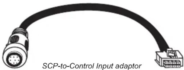
This multi-functional input is designed for HELIX DSP ULTRA S accessory products like a remote control which allows to adjust several features of the signal processor. Depending on the type of remote control, at first its functionality has to be defined in the “Device Configuration Menu” of the DSP PC-Tool software.
Attention: If the accessory product does not have a NanoFit connector, a SCP-to-Control Input adaptor (Art-Nr. M141313) is optionally available from your specialist dealer.
5. Ground Lift switch
The signal ground of the HELIX DSP ULTRA S is galvanically decoupled from the power ground. In many cars this setup is the best way to avoid alternator noise. Nevertheless, there are use cases where it will be necessary to directly connect input and output ground or to tie both grounds together via a resistor. Therefore the ground lift switch has three positions:
ISO: Input and output ground separated.
GND: Input and output ground tied together.
200Ω: Input and output ground connected via 200 Ohms resistor.
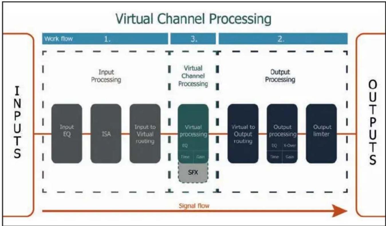
In addition to standard routing, the HELIX DSP ULTRA S offers Virtual Channel Processing (VCP), a multi-stage signal processing concept that enables the perfect configuration of complex sound systems, opening up completely new possibilities for sound tuning.
flowchart
graph LR
    subgraph Inputs
        A["Input EQ"] --> B["Input Processing"]
        C["ISA"] --> D["Input to Virtual routing"]
    end

    subgraph Virtual Processing
        E["Virtual processing EQ"] --> F["Output Processing"]
        G["SFX"] --> E
        H["Time Gain"] --> E
    end

    subgraph Outputs
        I["Virtual to Output routing"] --> J["Output processing"]
        K["X-Over"] --> L["Output limiter"]
        M["Time Gain"] --> L
    end

    style Inputs fill:#f9f,stroke:#333
    style Outputs fill:#bbf,stroke:#333
The VCP extends the previous scope of the device by an additional layer of processed channels, which is located between the inputs and outputs. A total of eight additional processed virtual channels and 12 processed output channels are available.
This virtual channel layer offers several advantages, especially in complex system configurations.
The main advantages of this concept are:
- Cross-channel group equalizers that affect several output channels simultaneously
- Multi-way speaker configuration of DSP sound effects (SFX)
- Additional features such as Rear Attenuation
For further information about the VCP and its configuration, please refer to our Knowledge Base at www.audiotec-fischer.com.
In order to configure a subwoofer remote control, specific settings have to be made in the DSP PC-Tool. First, the appropriate remote control must be activated in the "Extended Features" tab in the DCM menu of the DSP PC-Tool software and configured, depending on the model.
en

If the VCP is not activated, the subwoofer remote control of the DSP ULTRA S is permanently assigned to the output channels K and L. In this case it does not matter which output is named "Subwoofer" in the IO routing matrix.
In the "Outputs" menu you can also see to which outputs the SubRC (subwoofer remote control) is tied:
![DEP PC-TOOL | HELIX Outputs DCM FX 10 Time RTA ? Output F Output G Output H Output I Output J Output K [SubRC] Output L [SubRC] Front R Low Rear L Full Rear R Full Front Center High Front Center Low Subwoofer 1 Subwoofer 2](/content/2026/05/907442/images/c2591b404bfe5c532177098a3f376f6fbb5a167133dfc0bc3d3f66d0e609a9c5.jpg)
When VCP is activated, the subwoofer remote control is tied to the output channels that are supplied with one of the two virtual subwoofer signals ("Subwoofer 1" or "Subwoofer 2") in the "Virtual to Output Routing" matrix. This can be any combination of output channels.
In the following example these are the pre-amplifier outputs K and L:

![Subwoofer 1 100.0 % Subwoofer 2 100.0 % Subwoofer 1 Output K [SubRC] Subwoofer 2 Output L [SubRC]](/content/2026/05/907442/images/5ae68f44ba2cf88c285fa615a470016bbc52b9972e159a571123ecbaf9f74f25.jpg)
Note: Please note that an input signal must be assigned to the two virtual subwoofer signals "Subwoofer 1" and / or "Subwoofer 2" in the other routing matrices.
Afterwards, the subwoofer control is also displayed in the "Outputs" menu next to the name of the channel [SubRC]:
![DEP PC-TOOL | HELIX Outputs Virtual DCM FX IO Time RTA ? Output F Output G Output H Output I Output J Output K [SubRC] Output L [SubRC] Front R Low Rear L Full Rear R Full Front Center High Front Center Low Subwoofer 1 Subwoofer 2](/content/2026/05/907442/images/36cef9a5389d73175e42c1b02851f0b36010d4486bffe6a25d9032294b65b3dc.jpg)
Beside the unique DSP sound effects the DSP ULTRA S provides a bunch of new system and DSP features.
In the DCM menu of the DSP PC-Tool software individual settings can be made for several of these system features.
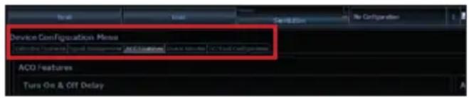
Turn On & Off Delay
This function allows to determine the delay time with which the DSP is switched on and off. The factory setting is 0.2 seconds. The delay time should only be modified if there are e.g. noises while switching on / off the signal processor.
URC Setup Switch Configuration
The ACO provides ten internal memory locations for sound setups instead of the common two.
By using an optional URC remote control or the Control pushbutton (see page 19) it is possible to toggle between two of the ten memory locations. These two memory locations can be determined in the "URC Setup Switch Configuration". The memory locations one and two are preassigned by default. To switch between all internal memory locations, the optionally available remote controls DIRECTOR and CONDUCTOR are recommended.
Remote Output Configuration
This function controls if the remote output (which switches on and off the connected amplifiers) will be temporarily deactivated during a sound setup switch. This function is activated (ON) by default.
DAC Digital Filter Config
A filter characteristic can be assigned to the DA converter of the module. The setting should be made according to your own preferences.
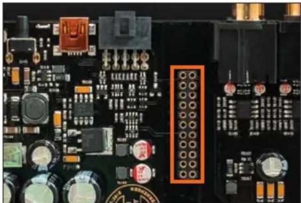
It is possible to extend the functionality of the HELIX DSP ULTRA S by inserting an optional HELIX Extension Card (HEC) – for example a High Definition Bluetooth® Audio Streaming module, a High Resolution Audio USB soundcard etc. To install a HELIX Extension Card it is necessary to remove the side panel of the DSP ULTRA S and replace it by the new side panel that comes with the HEC module.
Attention: Install the HEC module only in the designated device and its specific slot. Using the HEC module in other devices or slots can result in damage of the HEC module, the signal processor, the head unit / car radio or other connected devices!
Read in the following the steps how to install a HEC module:
- First disconnect all cables from the device.
- Dismantle the side panel where the USB input is located by removing the five Phillips screws.
- Pull out the bottom plate sideways.
- Prepare the module for installing it into the device. Any further mounting information will be found in the instruction manual of the respective HEC module.
- Insert the HEC module into the specific slot of the device which is marked in the following picture.
natural_image
Close-up of a computer motherboard with visible circuit components and connectors (no readable text or symbols)- Make sure that the HEC module is installed properly and all pins are fully inserted into the socket.

natural_image
Close-up of a circuit board with multiple LED connectors and a green checkmark overlay (no readable text or symbols)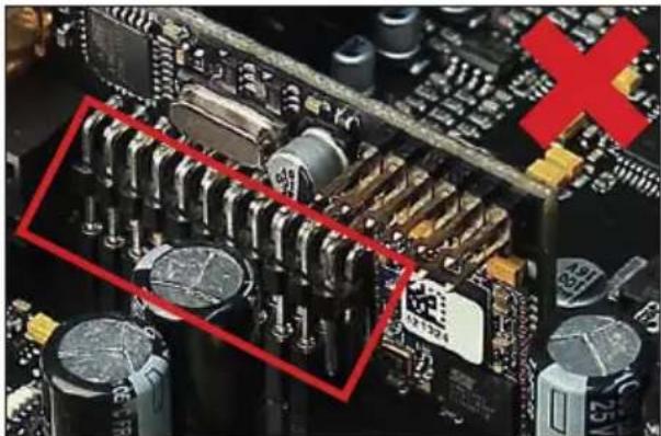
natural_image
Close-up of a computer motherboard with visible capacitors and a red X symbol (no readable text or symbols)- Reinsert the bottom plate and fix the new side panel which is delivered with the HEC module with the five Phillips screws.
- Bolt the HEC module to the side panel. Precise mounting information will be found in the instruction manual of the respective HEC module.
- Reconnect all cables to the device.
- Turn on the signal processor. The HEC module is automatically detected by the device and the Status LED of the HEC module lights up green.
- Now you are able to configure the HEC module in the DSP PC-Tool software.
| Inputs | 8 x RCA / Cinch |
| 8 x Highlevel speaker input | |
| 1 x Optical SPDIF (12 - 96 kHz) | |
| 1 x Coax SPDIF (12 - 192 kHz) | |
| 1 x Remote In | |
| Input sensitivity | RCA / Cinch: 1 - 8 Volts |
| Highlevel: 4 - 32 Volts | |
| Outputs | 12 x RCA / Cinch |
| 1 x Remote Out | |
| Output voltage | 8 Volts |
| Frequency response | 10 Hz - 44,000 Hz |
| DSP resolution | 64 Bit |
| DSP power | 2 x 295 MHz (2.4 billion MAC operations/sec.) |
| Sampling rate | 96 kHz |
| DSP type | 2 x Audio signal processor |
| Signal converters | A/D: Asahi Kasei 32 Bit |
| D/A: Asahi Kasei 32 Bit | |
| Signal-to-noise ratio (A-weighted) | Digital input: 117 dB |
| Analog input: 111 dB | |
| Total harmonic distortion (THD+N) | Digital input: < 0.0004 % |
| Analog input: < 0.0008 % | |
| IM distortion (IMD) | Digital input: < 0.0015 % |
| Analog input: < 0.003 % | |
| Crosstalk | >90 dB |
| Operating voltage | 9.6 - 17 Volts (max. 5 sec. down to 6 Volts) |
| Power rating | DC 12 V = 1.1 A max. |
| Current draw | 550 mA |
| Max. remote output current | 500 mA |
| Operating temperature range | -40°C to +70°C |
| Additional features | HEC slot, Ground lift switch, Smart Control Port, 32 Bit CoProcessor, ADEP.3 circuit, Auto Remote switch |
| Dimensions (H x W x D) | 40 x 177 x 170 mm / 1.58 x 6.97 x 6.69" |
The warranty service is based on the statutory regulations. Defects and damage caused by overload or improper handling are excluded from the warranty service. Any return can only take place following prior consultation, in the original packaging together with a detailed description of the error and a valid proof of purchase.
Technical modifications, misprints and errors excepted! For damages on the vehicle and the device, caused by handling errors of the device, we can't assume liability.
en
Trademarks

Bluetooth®
The Bluetooth® word mark and logos are registered trademarks owned by Bluetooth SIG, Inc. and any use of such marks by Audiotec Fischer GmbH is under license. Other trademarks and trade names are those of their respective owners.
Correct disposal of this product

This symbol means the product must not be discarded as household waste, and should be delivered to an appropriate collection facility for recycling. Follow local rules and never dispose of the product with normal household waste. Correct disposal of old products helps prevent negative consequences for the environment and human health.
Regular notes
CE
This product has been issued a CE marking. This means that the device is certified for use in vehicles within the European Union (EU).
UK CA
This product has been issued an UKCA marking. This means that the device is certified for use in vehicles within the United Kingdom.
EAC
This product has been issued an EAC marking. This means that the device is certified for use in vehicles within the Eurasian Customs Union.
AUDIOTEC
FISCHER
- Masseschalter
- Turn On & Off Delay
- Remote Output Configuration
- General instructions
- General installation instructions for HELIX components
- General instruction for connecting the HELIX DSP ULTRA S signal processor
- Configure the HELIX DSP ULTRA S as follows
- Configuration of the "Load Jumper" for the highlevel input
- To change the setting of the "Load Jumper", follow these steps:
- c. Removing the "Load jumper" / leaving it plugged in
- Overview "Load Jumper" configuration:
- d. Reassemble the signal processor
- Connecting the pre-amplifier inputs
- Connecting the highlevel speaker inputs
- Connecting a digital signal source
- Configuration of the remote input
- Connection to power supply & remote
- Make sure to disconnect the battery before installing the HELIX DSP ULTRA S!
- Connecting the PC & first start-up
- Adjustment of the input sensitivity of the analog signal inputs
- The gain control ranges are:
- Configuration of the DSP
- Analyzing the input signal
- Connecting the Line Outputs
- Sound tuning
- Optional: Adjustment of the ground connection
- Additional functions
- Clipping LED
- Control pushbutton
- Status LED
- SCP (Smart Control Port)
- Ground Lift switch
- URC Setup Switch Configuration
- DAC Digital Filter Config
- Trademarks
- Bluetooth®
- Correct disposal of this product
- Regular notes
Brand : Helix
Model : DSP ULTRA S
Category : Processor