CONDUCTOR - Uncategorized Audiotec Fischer - Free user manual and instructions
Find the device manual for free CONDUCTOR Audiotec Fischer in PDF.


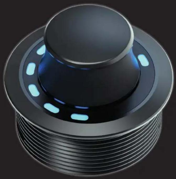
| Product Type | One-Touch Remote Control for ACO DSPs |
| Model | CONDUCTOR and CONDUCTOR PRO |
| Housing (CONDUCTOR) | ABS housing with brushed aluminum button |
| Housing (CONDUCTOR PRO) | Aluminum housing with ergonomic rotary knob with rubber-touch surface |
| Dimensions (CONDUCTOR) | Ø 46 mm x 28.7 mm |
| Dimensions (CONDUCTOR PRO) | Ø 46 mm x 36 mm |
| Installation Depth (CONDUCTOR) | 17 mm |
| Installation Depth (CONDUCTOR PRO) | 18 mm |
| Connection | SCP (Smart Control Port) or Control Input; no separate power supply required |
| Cable Length | 5 m (disconnectable: 4.8 m connecting cable + 0.2 m CONDUCTOR/PRO cable) |
| Hardware | Rotary encoder, 12x RGB LEDs, 48 MHz ARM processor |
| Compatibility (CONDUCTOR) | BRAX, HELIX and MATCH DSPs/amplifiers with ACO platform; SCP or Control Input |
| Compatibility (CONDUCTOR PRO) | BRAX, HELIX and MATCH DSPs/amplifiers with ACO and SCP |
| DSP PC-Tool Compatibility | CONDUCTOR: Version 4.75a and higher; CONDUCTOR PRO: Version 5 and higher |
| LED Feedback | 12 RGB LEDs for menu navigation, volume display, and error codes |
| Functions | Volume control (up to 4 volumes), ToneControl, Signal Input selection, Sound Setup selection, Bluetooth Playback Control (with optional module) |
| Cutout Diameter | Max 40 mm |
| Operating Principle | Turn and press knob; short press switches menus, long press confirms/mutes, double/triple press for track control |
| Installation Orientation | Adjustable in 30° steps; 12 o'clock reference for cable entry; LED alignment configurable in software |
| Power Supply | Via DSP (no separate power supply) |
| Warranty Disclaimer | Statutory warranty; excludes overload or improper handling |
Frequently Asked Questions - CONDUCTOR Audiotec Fischer
User questions about CONDUCTOR Audiotec Fischer
0 question about this device. Answer the ones you know or ask your own.
Ask a new question about this device
Download the instructions for your Uncategorized in PDF format for free! Find your manual CONDUCTOR - Audiotec Fischer and take your electronic device back in hand. On this page are published all the documents necessary for the use of your device. CONDUCTOR by Audiotec Fischer.
USER MANUAL CONDUCTOR Audiotec Fischer
One-Touch Remote Control for ACO DSPs
natural_image
3D rendering of a mechanical component with a circular top and threaded base, illuminated by blue light dots (no text or symbols)natural_image
Diagram of a car dashboard with steering wheel and red cross markers indicating no text or symbols (no readable text or labels)natural_image
Isometric technical diagram of a mechanical component with threaded base and mounting plate (no text or symbols)natural_image
Technical diagram of a mechanical assembly with a central component and a base ring, showing no text or symbols.CONDUCTOR PRO fixieren
natural_image
Technical diagram of a mechanical component with threaded base and mounting plate (no text or symbols)CONDUCTOR einsetzen
natural_image
Isometric line drawing of a mechanical component with concentric rings and mounting base (no text or symbols)natural_image
Circular mechanical component with evenly spaced slots and a small blue indicator block (no text or symbols)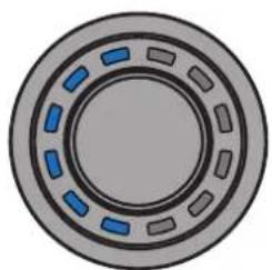
natural_image
Circular mechanical component with blue dashed segments on gray outer ring (no text or symbols)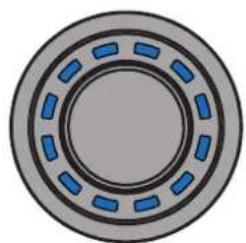
natural_image
Circular mechanical component with blue dashed segments and gray outer ring (no text or symbols)Gelb: High Frequency
natural_image
Circular mechanical component with segmented rings and central hub (no text or symbols)0 dB
natural_image
Circular mechanical component with dashed blue and gray segments, no visible text or symbols-6 dB
natural_image
Circular mechanical component with dashed inner lines and outer outer ring (no text or symbols)+6 dB
de
3.3 Signal Input selection menu (Signalquellenauswahlmenü)
natural_image
Circular mechanical component with green dashed segments on a gray outer ring (no text or symbols)natural_image
Circular mechanical component with segmented rings and yellow highlights (no text or symbols)natural_image
Circular mechanical component with red dashed markings, no visible text or symbolsnatural_image
Circular mechanical component with blue segments and a rotation arrow indicating clockwise motion (no text or symbols)Track zurück Play / Pause per langem
natural_image
Circular mechanical component with blue indicator lights, no text or symbols visibleTastendruck
natural_image
Diagram of a mechanical bearing or wheel with blue segments and an orange rotation arrow (no text or symbols)Track vor
4.1.1 Main menu (Hauptmenü)
natural_image
Circular mechanical component with blue dashed segments and gray outer ring (no text or symbols)natural_image
Circular mechanical component with blue dashed segments on a gray outer ring (no text or symbols)natural_image
Circular mechanical component with blue and gray segments, no text or symbols visible4.4 CONDUCTOR Status
natural_image
Circular mechanical component with red markings, no visible text or symbolsnatural_image
Circular mechanical component with red markings, no visible text or symbolsnatural_image
Circular mechanical component with red dashed segments and gray outer ring (no text or symbols)natural_image
Circular mechanical component with red dashed segments on a gray outer ring (no text or symbols)natural_image
Circular mechanical component with red dashed segments on gray background (no text or symbols)natural_image
Circular mechanical component with red dashed segments and gray outer ring (no text or symbols)natural_image
Circular mechanical component with alternating red and gray segments (no text or symbols)natural_image
Circular mechanical component with alternating red and gray segments (no text or symbols)- General information 25
- Installation instructions....26
2.1 Assembling the CONDUCTOR PRO 26
2.2 Assembling the CONDUCTOR 27
2.3 Connecting the CONDUCTOR / PRO to a DSP / DSP amplifier....28
- Operating the CONDUCTOR / PRO 29
3.1 Volume Control configuration (Volume menu 1 - 4)....31
3.2 ToneControl menu....32
3.3 Signal Input selection menu....32
3.4 Sound Setup selection menu....33
3.5 Bluetooth Playback Control menu....34
- Configuration in the DSP PC-Tool software....35
4.1 General configuration....35
4.1.1 Main menu....35
4.1.2 Automatic switch back to main menu....35
4.1.3 Menu activation....35
4.1.4 LED brightness....36
4.1.5 LED Dimming....36
4.1.6 Installation orientation....36
4.2 Volume Control Configuration 36
4.2.1 Volume selection....36
4.2.2 Assigned Volume control 36
4.2.3 Assigned color 36
4.2.4 Volume control range....37
4.2.5 Startup Volume 37
4.3 ToneControl 37
4.4 CONDUCTOR status .... 37
4.5 Loading and resetting CONDUCTOR settings....38
- Default configuration....39
- Troubleshooting ....40
- Technical data....42
- Legal information....44
en
Dear Customer,
Congratulations on purchasing this high-quality control unit with RGB-LED feedback.
We developed the CONDUCTOR based on state-of-the-art engineering and this is reflected in its exceptional quality and the impressive use of sophisticated technologies.
We hope you enjoy using this product.
The
AUDIOTEC FISCHER Team
1. General information
To make optimal use of all the possibilities afforded by the product, please carefully read through the following installation instructions. We guarantee that the flawless condition of every device has been checked before delivery.
We recommend appointing a specialist to install the product, as the verification of professional installation and connection of the device is a prerequisite for the warranty services.
Install your CONDUCTOR in a dry place in the car. Do not fit the device near parts that radiate heat or near the vehicle's electronic control units.
To protect against accidents, the CONDUCTOR must be professionally mounted so that the control unit does not pose a danger to passengers and/or the vehicle during a critical driving situation, such as emergency braking.
Information on professional installation is provided in the "Installation instructions" chapter on the following pages.
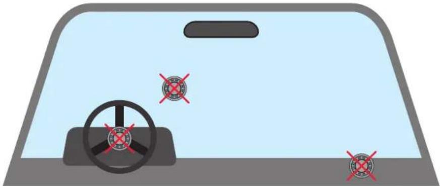
Important: During assembly, make sure that none of your vehicle's safety systems (e.g. airbag) are negatively affected in their function.
natural_image
Diagram of a car dashboard with steering wheel and red cross markers (no text or symbols)- Do not mount the CONDUCTOR on an airbag cover (e.g. steering wheel, A pillar or dashboard on the passenger side)
- Do not fasten the control unit in the driver's field of vision
- Do not place the CONDUCTOR loose on the dashboard
Before cutting the slot to mount the device, make sure that no electrical cables and components, etc., are concealed in the area behind it. Otherwise, these could be damaged. Please be aware that these kinds of parts may also be concealed in double-skin panelling.
The cable connections must be routed so that no risk of clamping, crushing or breakage exists. In case of sharp edges (sheet metal cutouts), all cables must be cushioned against chafing. In addition, the connecting cable must never be routed together with lines / cables for vehicle appliances (fan motors, fire detection modules, fuel lines, etc.).

2.1 Assembling the CONDUCTOR PRO
i. Cutting out the mounting slot
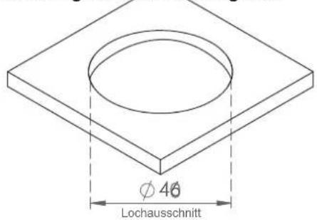
To ensure a safe and professional assembly, the cutout must not be more than 40 mm in size. Please make sure that the space between the CONDUCTOR PRO and other parts, such as switches, control elements, etc., is adequate with a sufficient installation depth. This is particularly important if installation slots need to be cut out. All the data on the installation depth and the diameter of the CONDUCTOR PRO is provided in the technical data in these instructions. Please make sure that the contact surface is as level and stable as possible.
natural_image
Isometric technical diagram of a mechanical component with threaded base and mounting plate (no text or symbols)Inserting the CONDUCTOR PRO
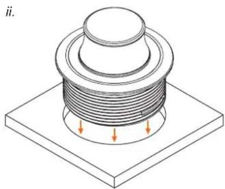
Insert the housing evenly into the panel cutout.
IMPORTANT: To avoid damage, never apply pressure to the rotary knob in the center of the CONDUCTOR PRO during installation. Press only on the surrounding housing.
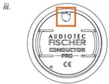
For correct alignment of the CONDUCTOR PRO, use the cable entry on the rear of the housing as a reference (see third figure on the left).
In the installed position, the cable entry must be aligned to the 12 o'clock position. If the installation situation prevents the CONDUCTOR PRO from being installed in the 12 o'clock position, it can also be rotated in 30° steps for installation. The LED display can then be adjusted to the installation position in the DSP PC-Tool software (see page 36, "Installation orientation").
natural_image
Technical diagram of a mechanical assembly with a central component and a base ring (no text or symbols)Securing the CONDUCTOR PRO
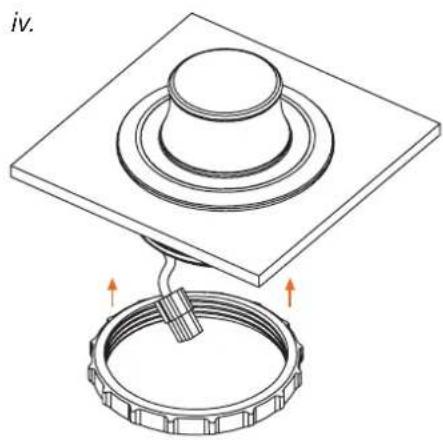
Once the CONDUCTOR PRO is in its final mounting position and the aluminum housing sits flush, route the 20 cm CONDUCTOR PRO cable through the mounting ring and then screw the ring onto the housing. Tighten the ring by hand.
Do not overtighten the ring, as this may cause damage to the CONDUCTOR PRO or the vehicle interior.
Routing and connecting the CONDUCTOR PRO connection cable
Route the 4.8 m connecting cable and connect it to the 20 cm CONDUCTOR PRO cable.
2.1 Assembling the CONDUCTOR
i. Cutting out the mounting slot
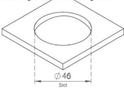
To ensure a safe and professional assembly, the cutout must not be more than 40 mm in size. Please make sure that the space between the CONDUCTOR and other parts, such as switches, control elements, etc., is adequate with a sufficient installation depth. This is particularly important if installation slots need to be cut out. All the data on the installation depth and the diameter of the CONDUCTOR is provided in the technical data in these instructions. Please make sure that the contact surface is as level and stable as possible.
en
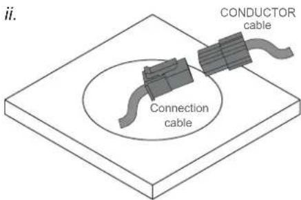
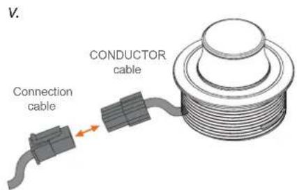
Routing and connecting the CONDUCTOR connection cable
Route the 4.8m connecting cable and guide it through the installation opening from the rear. Then connect the cable to the 20~cm CONDUCTOR cable.
natural_image
Technical line drawing of a mechanical component with mounting base and internal threading (no text or symbols)Inserting the CONDUCTOR
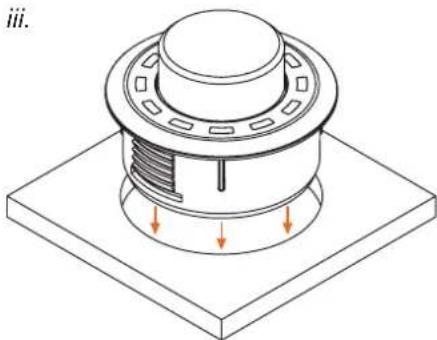
Press the housing evenly into the panel cutout.
IMPORTANT: To avoid damage, never push on the aluminum button in the center of the CONDUCTOR during assembly, only on the surrounding plastic housing.
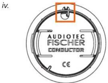
Use the 12 o'clock marking on the housing (see fourth figure on the left) as a guide to align the CONDUCTOR.
If the installation situation prevents the CONDUCTOR from being installed in the 12 o'clock position, it can also be rotated in 30° steps for installation. The LED display can then be adjusted to the installation position in the DSP PC-Tool software (see page 36, "Installation orientation").
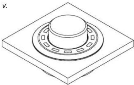
natural_image
Isometric line drawing of a mechanical component with concentric rings and mounting base (no text or symbols)The plastic housing should lie flush once you have moved the CONDUCTOR to its final installation position.
2.3 Connecting the CONDUCTOR / PRO to a DSP / DSP amplifier
- Connect the CONDUCTOR connection cable to the DSP / DSP amplifier
1.1 DSP / DSP amplifier with SCP (Smart Control Port)
Insert the SCP connector of the CONDUCTOR connection cable into the multifunction port (SCP) of the DSP / DSP amplifier.
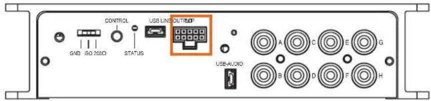
Note: If your CONDUCTOR is not equipped with a SCP connector ("for Control Input" version), an SCP-to-Control Input adaptor (art. no. M141313) is optionally available from your authorized dealer.
1.2 DSP / DSP amplifier with Control Input (only CONDUCTOR for Control Input)
If your DSP device is still equipped with a Control Input, insert the round connector of the CONDUCTOR connection cable into the multifunction port (Control Input) of the DSP / DSP amplifier.
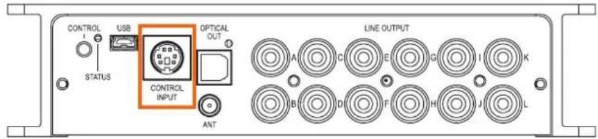
Turn your sound system on and then start the DSP PC-Tool software. You can find the software at www.audiotec-fischer.de/dsp-pc-tool (compatible from DSP PC-Tool software version 5).
Power is supplied to the CONDUCTOR / PRO via the DSP and it is switched on automatically.
- Open the „Remote Control“ menu (1) in the DSP PC-Tool. There (2), select the CONDUCTOR / PRO to open its configuration menu.

- You can now change other CONDUCTOR / PRO settings. More information on the configuration is provided on page 35 et seq., "Configuration in the DSP PC-Tool software".
- To complete the process, save the settings and the activation of the CONDUCTOR / PRO in the DSP / DSP amplifier by clicking on the "Save" button in the DSP PC-Tool.

3. Operating the CONDUCTOR / PRO
The CONDUCTOR is operated by turning and pressing the knob. The LED lighting provides feedback on the selected menu and the action performed.
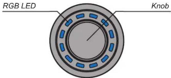

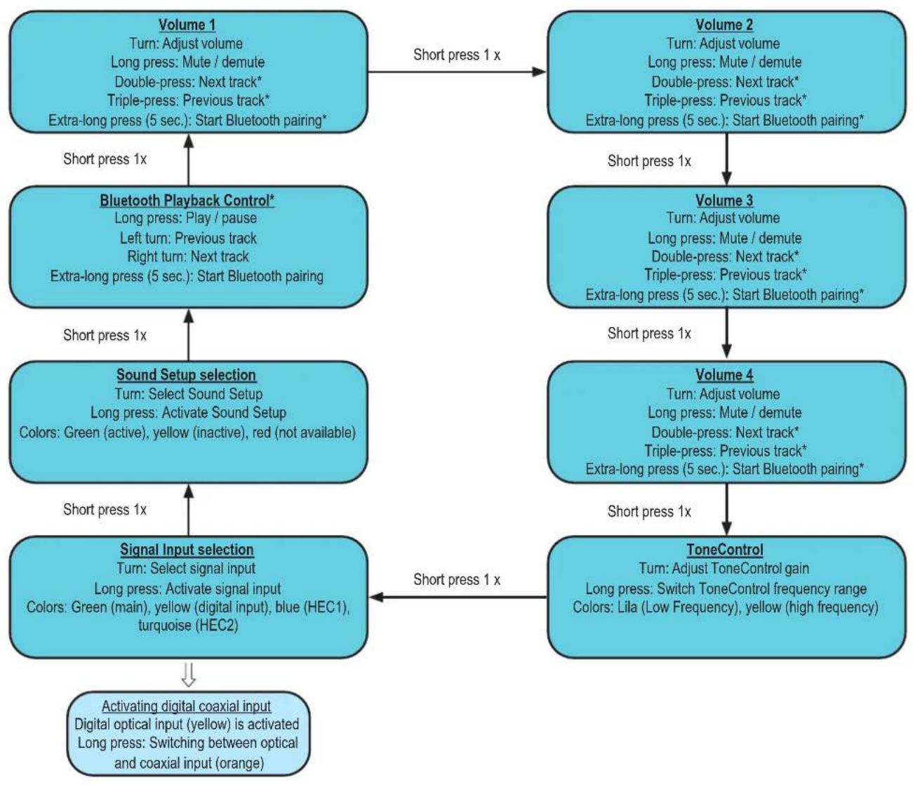
You can switch between the various menus by briefly pressing the button. The volume and the available menu options are selected by turning the knob. Pressing and holding the button confirms the selection or mutes the selected volume. In addition, if a Bluetooth module (BT Extension Card) is installed, the "Next track" function can be enabled by double-press and the "Previous track" function is enabled by triple-press in every volume menu. Further information on the functions and the LED feedback in a menu is provided on the following pages.
Note: If a menu or a volume is not enabled in the DSP PC-Tool, the next active menu or active volume is selected.
flowchart
graph TD
    A["Volume 1\nTurn: Adjust volume\nLong press: Mute / demute\nDouble-press: Next track*\nTriple-press: Previous track*\nExtra-long press (5 sec.): Start Bluetooth pairing*"] -->|Short press 1x| B["Volume 2\nTurn: Adjust volume\nLong press: Mute / demute\nDouble-press: Next track*\nTriple-press: Previous track*\nExtra-long press (5 sec.): Start Bluetooth pairing*"]
    B -->|Short press 1x| C["Volume 3\nTurn: Adjust volume\nLong press: Mute / demute\nDouble-press: Next track*\nTriple-press: Previous track*\nExtra-long press (5 sec.): Start Bluetooth pairing*"]
    C -->|Short press 1x| D["Volume 4\nTurn: Adjust volume\nLong press: Mute / demute\nDouble-press: Next track*\nTriple-press: Previous track*\nExtra-long press (5 sec.): Start Bluetooth pairing*"]
    D -->|Short press 1x| E["ToneControl\nTurn: Adjust ToneControl gain\nLong press: Switch ToneControl frequency range\nColors: Lila (Low Frequency), yellow (high frequency)"]
    E -->|Short press 1x| F["Signal Input selection\nTurn: Select signal input\nLong press: Activate signal input\nColors: Green (main), yellow (digital input), blue (HEC1), turquoise (HEC2)"]
    F -->|Short press 1x| G["Activating digital coaxial input\nDigital optical input (yellow) is activated\nLong press: Switching between optical and coaxial input (orange)"]
    G --> H["Short press 1x"]

    I["Bluetooth Playback Control*\nLong press: Play / pause\nLeft turn: Previous track\nRight turn: Next track\nExtra-long press (5 sec.): Start Bluetooth pairing"] --> H
    J["Sound Setup selection\nTurn: Select Sound Setup\nLong press: Activate Sound Setup\nColors: Green (active), yellow (inactive), red (not available)"] --> J
    K["Volume 4\nTurn: Adjust volume\nLong press: Mute / demute\nDouble-press: Next track*\nTriple-press: Previous track*\nExtra-long press (5 sec.): Start Bluetooth pairing*"] --> J
    L["Volume 3\nTurn: Adjust volume\nLong press: Mute / demute\nDouble-press: Next track*\nTriple-press: Previous track*\nExtra-long press (5 sec.): Start Bluetooth pairing*"] --> L
Note: Menu navigation is cyclic. The menu sequence begins in the present menu.
3.1 Volume Control Configuration (Volume menu 1 - 4)
The four volume menus let you separately control up to 4 different volumes (master, digital, HEC/AUX, subwoofer volume, Rear Attenuation, etc.). These can be set as described under point 4.2 "Volume Control Configuration" on page 36 The volume menus are restored to the most recently set values after restarting the system. If the "Startup volume" option (see page 37, point 4.2.5) has been configured, the volume is switched back on at the maximum set limit level, if this was exceeded when the device was switched off.
If a volume is turned down completely, the volume is muted independent of the set range.
Actions:
Turn: Set volume level
Long press: Mute / demute
Double-press: Nexttrack*
Triple-press: Previous track*
Extra-long press (5 sec.): Start Bluetooth pairing*
LED feedback:
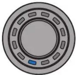
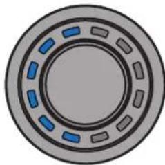
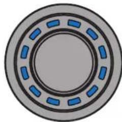
The set volume level is displayed by the bottom-left LEDs in a clockwise direction in the color assigned for the volume. Muting (long press) is signaled by a single rotating LED.
Changing the volume when muted cancels the muting.
natural_image
Circular mechanical component with evenly spaced slots and a small blue indicator on the center (no text or symbols)Minimum volume
natural_image
Circular mechanical component with blue and gray segments, no text or symbols visible50 % volume
natural_image
Circular mechanical component with blue internal segments and gray outer ring (no text or symbols)Maximum volume
3.2 ToneControl menu
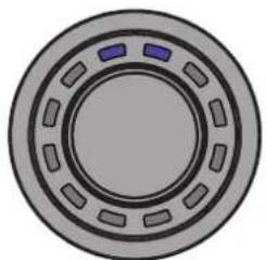
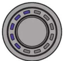
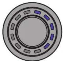
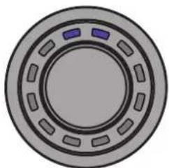
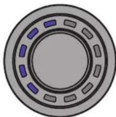
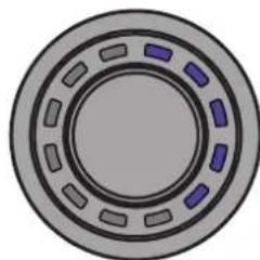
The ToneControl menu allows you to adjust the sound using a high and low shelf filter. The volume can be changed in the range from -6 dB to +6 dB, allowing you to boost or cut the highs and lows as desired.
The frequencies for the high and low shelf filters can be defined individually in the DSP PC-Tool software (see page 37, point 4.3).
Actions:
Turn: Adjust ToneControl gain
Long press: Switch ToneControl frequency range (High Frequency / Low Frequency)
LED feedback:
Lila: Low Frequency
Ywellow: High Frequency
natural_image
Circular mechanical component with evenly spaced slots and two small purple components on top (no text or symbols)0 dB
natural_image
Circular mechanical component with dashed blue and gray segments, no text or symbols visible-6 dB
natural_image
Circular mechanical component with segmented rings and a central hub (no text or symbols)+6 dB
3.3 Signal Input selection menu
The "Signal Input selection" menu lets you switch between the signal sources connected to the DSP / DSP amplifier. The menu starts with the currently selected or most recently active input.
Actions:
Turn: Select signal input Long press: Activate signal input
LED feedback:
Green: Maininput
Yellow: Digital optical input
Orange: Digital coaxial input (Input can only be selected when the optical digital input is activated / see below)
Blue: Extension Card 1 (HEC1)
Turquoise: Extension Card 2 (HEC2 – only BRAX DSP)
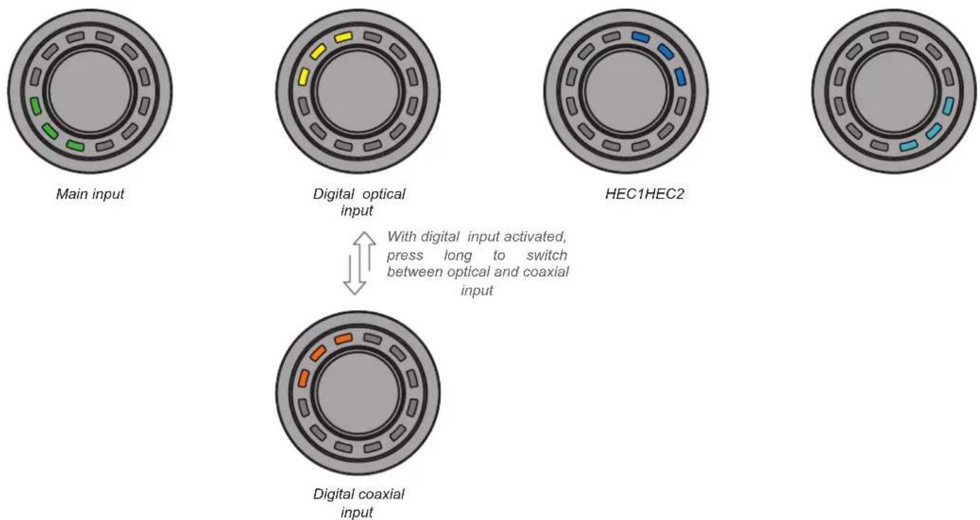
Note: The CONDUCTOR automatically detects the signal inputs of the connected DSP / DSP amplifier. Only the available signal inputs can be selected. All other inputs are not displayed by LED feedback and cannot be selected.
3.4 Sound Setup selection menu
The "Sound Setup selection" menu lets you switch between the DSP's up to 10 Sound Setups. The menu starts with the currently selected or most recently active Sound Setup.
en
Actions:
Turn: Select Sound Setup
Long press: Activate Sound Setup
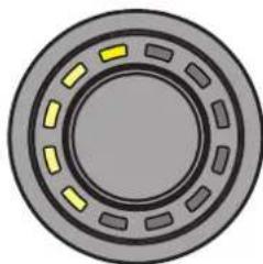
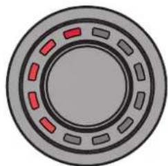
LED feedback:
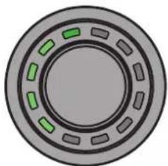
Green: Sound Setup active
Yellow: Sound Setup memory space occupied, setup inactive
Red: Sound Setup memory space empty, cannot be selected
You can use the CONDUCTOR to select and enable the DSP's 10 Sound Setup memory spaces. The memory spaces are displayed as follows:
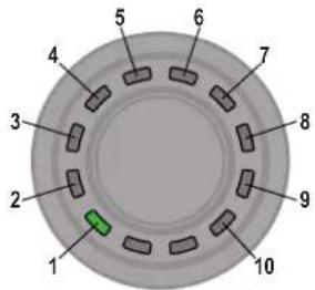
Examples of the LED feedback in the "Sound Setup selection" menu:
natural_image
Circular mechanical component with green dashed segments on a gray outer ring (no text or symbols)Sound Setup no. 5 enabled
natural_image
Circular mechanical component with segmented rings and yellow highlights (no text or symbols)Sound Setup no. 5 available – can be enabled by holding down the button
natural_image
Circular mechanical component with red dashed segments on a gray background (no text or symbols)Sound Setup no. 5 not occupied and can also not be selected
3. Operating the CONDUCTOR / PRO
3.5 Bluetooth Playback Control menu\*
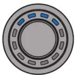
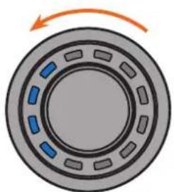
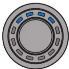
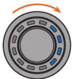
The "Bluetooth Playback Control" menu lets you control an optionally installed Bluetooth module (play / pause, next / previous track, enable pairing mode). The menu always starts with the play / pause function (four top LEDs lit).
Actions:
Turn: Perform action automatically
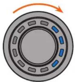
Left turn: Counter-clockwise: Previous track
Right turn: Clockwise: Next track
Long press: Play / pause
Extra-long press (5 sec.): Start Bluetooth pairing
LED feedback:
natural_image
Diagram of a mechanical bearing or wheel with blue segments and an orange rotation arrow (no text or symbols)Previous track Play / pause by a long
natural_image
Circular mechanical component with segmented rings and blue highlighted sections (no text or symbols)press of the button
natural_image
Diagram of a mechanical bearing or wheel with blue segments and an orange rotation arrow (no text or symbols)Next track
Overview of the configuration menu
The configuration menu is located in the "Remote Control" menu of the DSP PC-Tool software. However, the menu is only visible if you have selected the CONDUCTOR / PRO as described on page 28.
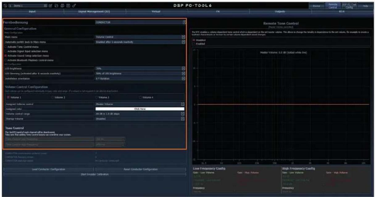
All CONDUCTOR settings are changed in the configuration menu.
The menu is divided into the "General Configuration", "Volume Control Configuration" and "Status" area.
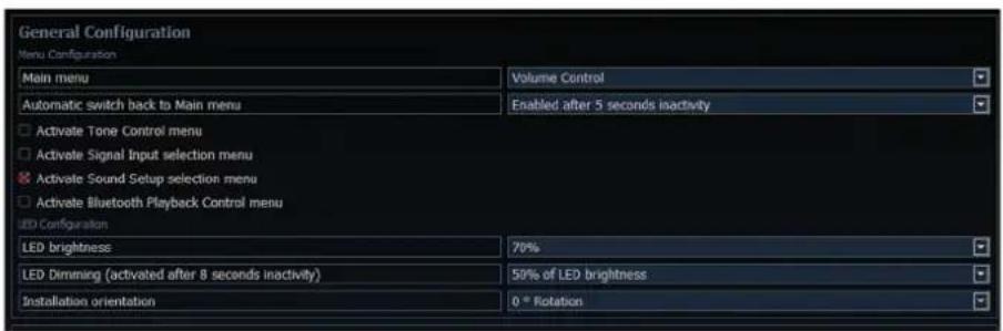
4.1 General Configuration
The “General Configuration” area is used for all the basic Menu Configuration and LED display (LED Configuration) settings.
4.1.1 Main menu
This is where the CONDUCTOR's start menu, which is accessed immediately after the DSP is switched on, is defined.
Volume Control, Signal Input selection, Sound Setup selection and Bluetooth Playback Control menu are available for selection.
4.1.2 Automatic switch back to main menu
If the function is enabled, the CONDUCTOR switches back to the set "Main menu" after around 5 seconds, if another menu was previously selected. If the function is disabled, the currently selected menu remains selected until it is manually changed by briefly pressing the button.
4.1.3 Menu activation
This lets you enable and disable the volume controls as well as other menus. If a menu is disabled, it cannot be selected by the CONDUCTOR.
Note: The "Volume Menu" is always enabled and can only be switched off by disabling all four volumes in the "Volume Control Configuration" (see point 4.2).
An enabled menu can be recognized by a red cross in front of the menu name.

Note: The start menu set in the "Main menu" is automatically enabled.
4.1.4 LED brightness
This lets you set the brightness of the LED lighting. This is set to 70 % by default.
4.1.5 LED Dimming
This menu lets you configure the optional dimming of the LEDs. When this function is enabled, the LEDs are automatically dimmed by the configured value or switched off completely after 8 seconds of inactivity.
5% - 75% of LED brightness: The LEDs are dimmed by the set percentage based on the set LED brightness. A dimming level of 50% is set by default. The selection range may be restricted depending on the set brightness of the LED lighting (LED brightness).
Example: LED brightness 50 %, LED dimming 50 %
The set LED brightness of 50 % is now dimmed by an additional 50 %.
Disabled: Switches the "LED dimming" off.
LEDs off: Switches the LED lighting off completely.
4.1.6 Installation orientation
If the installation situation prevents the CONDUCTOR from being installed in the 12 o'clock position, it can also be rotated in 30° steps for installation. The LED display can then be adapted to the installation position in the DSP PC-Tool software (see page 26 - 27, "Assembling the CONDUCTOR").
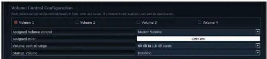
4.2 Volume Control Configuration
This lets you individually configure up to four selectable volumes. Any volume that is not required can also be disabled.
Note: If all four volumes are disabled, the entire "Volume Control" menu is disabled.
4.2.1 Volume selection
This is where the volume to be configured can be selected. The red cross indicates which of the four volumes is being configured.
4.2.2 Assigned Volume control
This is where a volume control can be assigned to the previously selected volume. The selection may vary depending on the DSP product.
Disabled: Switches the selected volume off
Master Volume: Volume control for the global master volume
Subwoofer Volume: Volume control for the subwoofer
Digital Input Volume: Volume for the digital input (optical and electric)
HEC/AUX 1 Volume: Volume for an optionally installed Extension Card or an AUX input
HEC/AUX 2 VolumeVolume for an optionally installed Extension Card or an AUX input (only BRAX DSP)
Rear Attenuation Volume: For DSP products with VCP, the volume of the virtual channels "Rear L Full" and "Rear R Full" can be controlled separately when Virtual Channel Processing is enabled.
4.2.3 Assigned color
This is where an individual color can be assigned to every volume in order to quickly and easily distinguish between different volumes.
All other menus have fixed color concepts.
4.2.4 Volume control range
For each of the four volumes, the gradation of the volume control can be set separately for the relevant application.
60 dB in 1.0 dB steps: This is the optimal setting for most applications. The large control range and good gradation makes it particularly suitable for the master and source volumes (HEC / AUX / Digital Input).
60 dB in 0.5 dB steps: The fine individual steps enables a very precise volume setting.
24 dB in 0.5 dB steps: This setting provides a smaller control range, making it particularly suitable for the Rear Attenuation volume, as this volume often only requires a minor adjustment to the rendition.
12 dB in 0.5 dB steps: This setting provides a smaller control range, making it particularly suitable for the subwoofer volume, as this volume often only require a minor adjustment to the rendition.
4.2.5 Startup Volume
This lets you limit the startup volume. If this option is “Disabled”, the most recently set volume is always restored when the system is switched on. To prevent the system from being switched on at an excessive volume, this area lets you limit the maximum “Startup Volume”. This limitation only applies for the startup process and has no influence on the maximum adjustable volume during operation.
Example: If the sound system is switched off while the master volume is turned all the way up, the system will also use this volume when it is next switched on if "Startup Volume" is not activated. Using "Startup Volume" lowers the volume to the set value when switching the system back on, if the volume previously set was higher. If the system is switched off at a lower level, the lower volume is used when the system is switched back on regardless of which option is selected here.
Disabled: The volume is always set to the most recently used value when the system is switched back on.
Limited to -15 dB: The volume is set to maximum -15 dB (max. 3/4 of the total volume range) when the system is switched back on, if the volume exceeded the value when it was switched off.
Limited to -30 dB: The volume is set to maximum -30 dB (max. half of the total volume range) when the system is switched back on, if the volume exceeded the value when it was switched off.
Limited to -45 dB: The volume is set to maximum -45 dB (max. 1/4 of the total volume range) when the system is switched back on, if the volume exceeded the value when it was switched off.
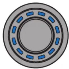
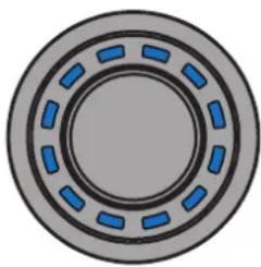
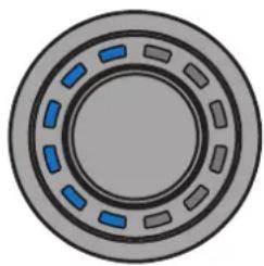
Application example at 100 % volume level:
natural_image
Circular mechanical component with blue dashed segments on a gray background (no text or symbols)Volume level before switch off (100 %)
natural_image
Circular mechanical component with blue dashed inner ring and gray outer ring (no text or symbols)Disabled – Volume after switch back on (100 %)
natural_image
Circular mechanical component with blue and gray segments, no text or symbols visibleLimited to -30 dB – Volume after switch back on (50 %)
4.3 ToneControl
In this menu, the frequency ranges in which the volume boost or attenuation is applied can be defined. The gain control range is from -6 dB to +6 dB and cannot be changed.
To make adjustments, the menu must first be enabled in the Menu Activation section (see page 35, section 4.1.3).

4. Configuration in the DSP PC Tool software
4.4 CONDUCTOR status
This is where all important information on the CONDUCTOR's status can be found.

CONDUCTOR communication protocol version: Shows the current version of the communication protocol.
CONDUCTOR firmware version: Shows the currently installed CONDUCTOR firmware. The firmware is automatically updated when opening the DSP PC-Tool software.
CONDUCTOR operation status: Shows the CONDUCTOR's operation status.
4.5 Loading and resetting CONDUCTOR settings
At this point, configuration settings of a CONDUCTOR can be imported into DSP PC-Tool 6 from older DSP PC-Tool versions (4.75a to 5) using a CONDUCTOR configuration file (“.afcc” file).
In addition, the entire configuration can be reset to the factory default settings.

flowchart
graph TD
    A["Load Conductor Configuration"] --> B["Reset Conductor Configuration"]
    B --> C["Start Encoder Calibration"]
5. Default configuration
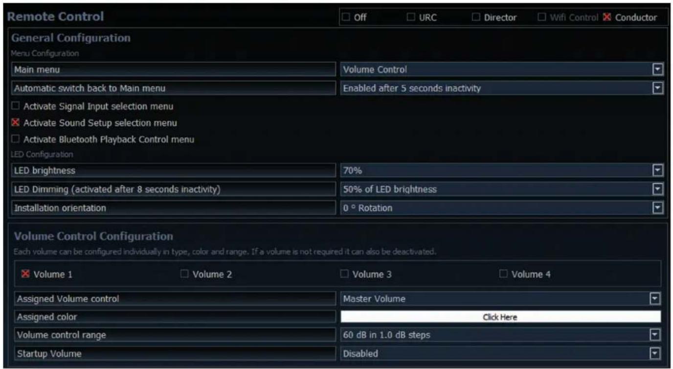
The following options are configured in the as-delivered condition:
- Main menu: Volume Control → The CONDUCTOR always starts with the selected Master Volume.
- Automatic switch back to main menu: Enabled → The CONDCUTOR automatically switches back to the Master Volume menu after 5 seconds of inactivity.
- Only the "Sound Setup selection" menu is enabled by default, which lets you switch between the different DSP memory spaces. The "Signal Input selection" menu as well as the "Bluetooth Playback Control" menu are disabled by default. This means that two "Volume Control" menus (master and subwoofer volume) as well as the "Sound Setup selection" menu are active in the as-delivered condition.
- LED brightness: 70% The default brightness is 70% of the maximum brightness.
- LED dimming: 50 % of LED brightness The brightness is reduced by 50 % after 8 seconds of inactivity.
- Installation orientation: 0^ rotation The rotation is set to off by default, so the conductor's locking notch is in the 12 o'clock position.
- Volume 1 → This volume is configured as the “Master Volume” by default. The volume is white and has a control range of 60 dB, which can be controlled in 1 dB steps. The “Startup Volume” is disabled by default, meaning that the previously set volume is used whenever the system is restarted.
- Volume 2 → This volume is configured as the "Subwoofer Volume" by default. The volume is red and has a control range of 24 dB, which can be controlled in 0.5 dB steps. The "Startup Volume" is disabled by default, since this function is not needed for the "Subwoofer Volume".
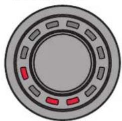
Problem: CONDUCTOR is displaying an error code
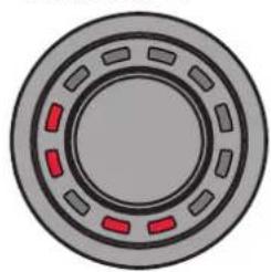
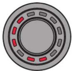
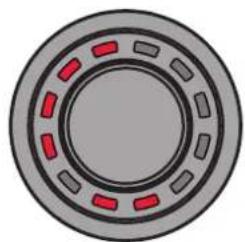
If a problem occurs when establishing a connection, the CONDUCTOR displays various error codes.
Error code 1:
natural_image
Circular mechanical component with red and gray segments, no visible text or symbolsCause: The connected device is not supported. The CONDUCTOR is only compatible with devices that are equipped with the ACO platform.
There may also be an interruption in the supply line, which prevents a connection between the DSP and CONDUCTOR.
Solution: Please check the cable and the plug connection to ensure that everything is connected correctly.
Error code 2:
natural_image
Circular mechanical component with red dashed segments on gray background (no text or symbols)Cause: The CONDUCTOR software is not current and requires an update.
Solution: Connect your DSP / DSP amplifier to a PC and start the latest DSP PC-Tool software. The CONDUCTOR is then updated automatically.
Error code 3:
natural_image
Circular mechanical component with red dashed segments on gray background (no text or symbols)Cause: The ACO platform of the DSP / DSP amplifier is not current and requires an update.
Solution: Connect your DSP / DSP amplifier to a PC and start the latest DSP PC-Tool software. The ACO update then starts automatically.
Error code 4:
natural_image
Circular mechanical component with red dashed segments on a gray background (no text or symbols)Cause: The CONDUCTOR is not enabled in the DSP / DSP amplifier.
Solution: Enable the CONDUCTOR as described on page 28 in the Chapter 2.3 "Connecting the CONDUCTOR to a DSP / DSP amplifier".
Error code 5:
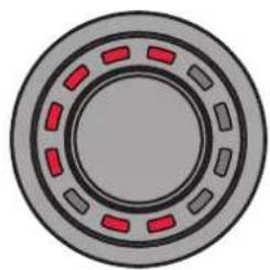
natural_image
Circular mechanical component with red dashed markings on a gray background (no text or symbols)Cause: Repeated transmission errors have occurred between the CONDUCTOR and the DSP / DSP amplifier's ACO platform.
Solution: Check the cable for damage and tight fit of the plug connector.
Error code 6:
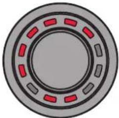
natural_image
Circular mechanical component with red dashed segments on gray background (no text or symbols)Cause: DSP in the signal processor / DSP amplifier is not started.
Solution: Connect your DSP / DSP amplifier to a PC and start the latest DSP PC-Tool software. Update the software of the DSP with the latest DSP PC-Tool.
en
Fehlercode 7:
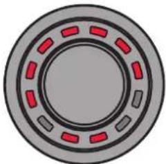
natural_image
Circular mechanical component with red dashed segments on a gray outer ring (no text or symbols)Cause: The connected device is in Protection Mode.
Solution: Fix the cause of the Protection Mode. Further information can be found in the respective manual of the DSP / DSP amplifier under the point "Satuts LED".
Error code 8:
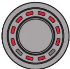
natural_image
Circular mechanical component with red dashed segments on a gray background (no text or symbols)Cause: An unknown error has occurred.
Solution: Check all plug connections and use the latest version of the DSP PC-Tool.
Problem: CONDUCTOR does not turn on
Possible cause: Faulty plug connection.
Solution: Check the tight fit of the plug connector.
Problem: LED lighting off
Possible cause: The "LED Dimming" setting is configured to "LEDs off", which will turn off the illumination after 8 seconds of inactivity. If this is not the case, check the wiring.
Solution: Enable the LED feedback rendition as described on page 36 in point 4.1.5 "LED Dimming".
Problem: No sound
Possible cause: Volume set too low; mute activated; incorrect input source.
Solution: Check volume level of Volumes 1 - 4 and whether they have been activated in the DSP PC-Tool; disable mute (muting is signalled by a single rotating LED / demuting: The knob must be pressed for a long time or turned when the volume menu is selected); change input source.
Problem: No connection with compatible device possible
Possible cause: Transmission problem to the DSP; incompatible software versions.
Solution: Check the tight fit of the CONDUCTOR plug connector; update the CONDUCTOR and ACO software with the current DSP PC-Tool.
CONDUCTOR PRO
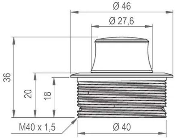
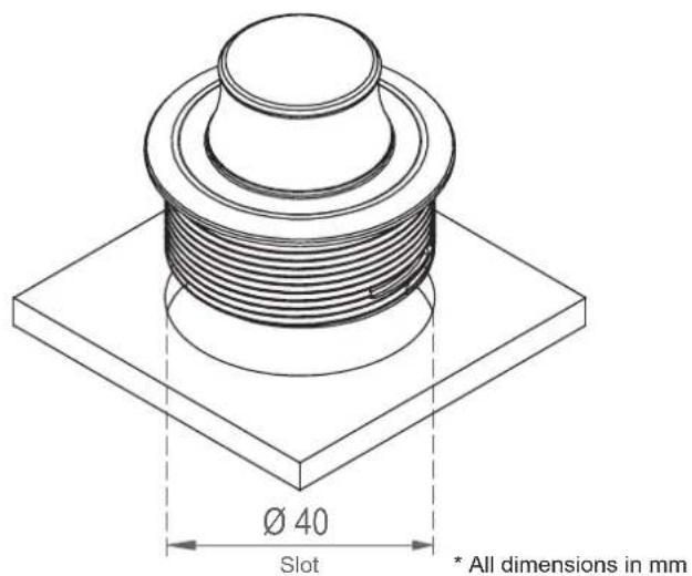
| Housing Aluminum housing with ergonomic rotary knob with rubber-touch surface on the side | |
| Hardware otary encoder, 12x RGB LEDs and 48 MHz ARM processor | |
| Connection SCP (Smart Control Port) / no separate power supply required | |
| Cable length 5 m – disconnectable, 4.8 m connecting cable+ 0.2 m CONDUCTOR PRO cable | |
| Dimensions (ø x H) | ø 46 x 36 mm |
| Installation depth 18 mm / 0.71" | |
| Compatibility The CONDUCTOR is exclusively intended for BRAX, HELIX and MATCH DSPs /DSP amplifiers with ACO (Advanced CoProcessor) and SCP (Smart Control Port).A current compatibility overview is available at www.audiotec-fischer.de/conductor-pro | |
| DSP PC Tool compatibility Version 5 and higher | |
CONDUCTOR
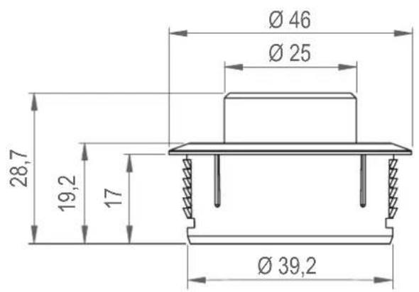
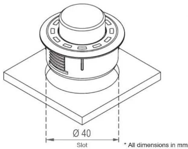
| Housing ABS housing with brushed aluminum button | |
| Hardware Rotary encoder, 12x RGB LEDs and 48 MHz ARM processor | |
| Connection SCP (Smart Control Port) or Control Input / no separate power supply required | |
| Cable length 5 m – disconnectable, 4.8 m connecting cable+ 0.2 m CONDUCTOR cable | |
| Dimensions (ø x H) | ø 46 x 28.7 mm |
| Installation depth 17 mm / 0.67" | |
| Compatibility The CONDUCTOR is exclusively intended for BRAX, HELIX and MATCH DSPs /DSP amplifiers with ACO (Advanced CoProcessor). A current compatibility overview is available at www.audiotec-fischer.de/conductor | |
| DSP PC Tool compatibility Version 4.75a and higher | |
Warranty disclaimer
The warranty service is based on the statutory regulations. Defects and damage caused by overload or improper handling are excluded from the warranty service. Any return can only take place following prior consultation, in the original packaging together with a detailed description of the error and a valid proof of purchase.
Technical modifications, misprints and errors excepted! For damages on the vehicle and the device, caused by handling errors of the device, we can't assume liability.
Trademarks

Bluetooth®
® word mark and logos are registered trademarks owned by Bluetooth SIG, Inc. and any use of such marks by Audiotec Fischer GmbH is under license. Other trademarks and trade names are those of their respective owners
Correct disposal of this product

This symbol means the product must not be discarded as household waste, and should be delivered to an appropriate collection facility for recycling. Follow local rules and never dispose of the product with normal household waste. Correct disposal of old products helps prevent negative consequences for the environment and human health.
Regular notes

This product has been issued a CE marking. This means that the device is certified for use in vehicles within the European Union (EU).

This product has been issued an UKCA marking. This means that the device is certified for use in vehicles within the United Kingdom.

This product has been issued an EAC marking. This means that the device is certified for use in vehicles within the Eurasian Customs Union.
en
AUDIOTEC
FISCHER
- CONDUCTOR PRO fixieren
- CONDUCTOR einsetzen
- Signal Input selection menu (Signalquellenauswahlmenü)
- Main menu (Hauptmenü)
- CONDUCTOR Status
- General information
- Assembling the CONDUCTOR PRO
- Inserting the CONDUCTOR PRO
- Securing the CONDUCTOR PRO
- Routing and connecting the CONDUCTOR PRO connection cable
- Assembling the CONDUCTOR
- Routing and connecting the CONDUCTOR connection cable
- Inserting the CONDUCTOR
- Connecting the CONDUCTOR / PRO to a DSP / DSP amplifier
- Operating the CONDUCTOR / PRO
- Volume Control Configuration (Volume menu 1 - 4)
- Actions:
- LED feedback:
- ToneControl menu
- Signal Input selection menu
- Sound Setup selection menu
- Bluetooth Playback Control menu\*
- Overview of the configuration menu
- General Configuration
- Main menu
- Automatic switch back to main menu
- Menu activation
- LED brightness
- LED Dimming
- Installation orientation
- Volume Control Configuration
- Volume selection
- Assigned Volume control
- Assigned color
- Volume control range
- Startup Volume
- ToneControl
- Configuration in the DSP PC Tool software
- Loading and resetting CONDUCTOR settings
- Default configuration
- Problem: CONDUCTOR is displaying an error code
- Error code 6:
- Fehlercode 7:
- Error code 8:
- Problem: CONDUCTOR does not turn on
- Problem: LED lighting off
- Problem: No sound
- Problem: No connection with compatible device possible
- Warranty disclaimer
- Trademarks
- Correct disposal of this product
- Regular notes
Brand : Audiotec Fischer
Model : CONDUCTOR
Category : Uncategorized