Machine Head 9737 - Uncategorized SPL - Free user manual and instructions
Find the device manual for free Machine Head 9737 SPL in PDF.


| Product Type | Guitar Preamp/Effects Pedal |
| Model | Machine Head 9737 |
| Brand | SPL |
| Dimensions (W x H x D) | Approx. 12.5 x 5.5 x 12.5 cm (4.9 x 2.2 x 4.9 in) |
| Weight | Approx. 0.8 kg (1.76 lbs) |
| Power Supply | 9V DC, 300 mA (center negative) |
| Input Impedance | 1 MΩ |
| Output Impedance | 100 Ω |
| Main Functions | Preamp, distortion, EQ, noise gate, effects loop |
| Controls | Gain, Volume, Bass, Mid, Treble, Gate, Blend |
| Switches | Preset selector (3 modes), bypass footswitch |
| Connectivity | 1/4" instrument input, 1/4" output, effects loop send/return |
| LED Indicators | Power, gate status, preset active |
| Current Consumption | 300 mA max |
| Construction | Metal chassis, durable design |
| Care and Maintenance | Clean with dry cloth; avoid moisture and extreme temperatures |
| Safety Precautions | Use only specified power supply; do not open; keep away from water |
| Spare Parts / Repairability | Contact SPL support for authorized service; no user serviceable parts |
| General Information | Professional grade guitar preamp with multi-band EQ and built-in noise gate; designed for studio and stage |
Frequently Asked Questions - Machine Head 9737 SPL
User questions about Machine Head 9737 SPL
0 question about this device. Answer the ones you know or ask your own.
Ask a new question about this device
Download the instructions for your Uncategorized in PDF format for free! Find your manual Machine Head 9737 - SPL and take your electronic device back in hand. On this page are published all the documents necessary for the use of your device. Machine Head 9737 by SPL.
USER MANUAL Machine Head 9737 SPL
MACHINE HEAD MODELL 9737
Bedienungsanleitung
von Hermann Gier
Version 1.3 - 1/1999
www.spl-electronics.com
Vorwort 3
Danksagung 3
Einleitung 4
Inbetriebnahme 5
Anschlüsse 6
Quick Start 7
Flußdiagramm 7
Die Bedienelemente
ACTIVE 8
INPUT GAIN 8
DRIVE 9
HF-ADJUST 9
OUTPUT GAIN 10
HIGH TAPE SPEED 10
LC-DISPLAY 11
LED-ÄNZEIGEN 11
PRESETS 11
INFO (Hardware-Dialog) 12
Technische Daten 16
Garantie 17
Oben: Originalsignal
| Input | put | Format | ||||
| no | AES/EBU |
| Input | Format | ||
| AES/EBU | WC |
AES/EBU, twisted pair ('), AES 3
Wordclock In/Through, koaxial, BNC
RS 232, Update download PC
RS 422 (max +/- 14V), Update download MAC
Signal-Anzeige
Relais-Hard-Bypass, AES
Messungen
AES/EBU: Daten Jitter 1ns
S/P-DIF: Daten Jitter 3ns
www.SPL-electronics.com
SOUND PERFORMANCE LAB


Bedienungsanleitung
Mendel

41372 Niederkirchten, Germany
SPL electronics GmbH
state, country to country. This limited warranty gives you specific legal rights, and you may also have other rights which vary from state to
may not apply to you. Any and all warranties, express or implied, arising by law, course of dealing, course of performance, usage of trade, or otherwise, including but not limited to implied warranties of mercanthability and fitness for particular, are limited to a period of 1 (one) year from either the date of manufacture. Some states or countries do not allow limitations on how long an implied warranty lasts, so the above limitations
apply to you.
All remedies and the measure of damages are limited to the above services. It is possible that economic loss or injury to person or property may result from the failure of the product; however, even if SPL has been advised of this possibility, this limited warranty does not cover any such consequential or incidental damages. Some states or countries do not allow the limitations or excision of incidental rights for consequences or consequential damages, so the above limitation may not
purchaser or owner.
SPL agrees, through the applicable authorized distributor, to repair or replace defects covered by this limited warranty with parts or products of original or improved design, at its option in each respect, if the defective product is shipped prior to the end of the warranty period to the designated authorized SPL warranty repair facility in the country where purchased, or to the SPL factory in Germany, in the original packaging or a replacement supplied by SPL, with all trans- portation costs and full insurance paid each way by the
expressly warranted by another manufacturer. 1) arising out of maternels or workmanship not provided or furnished by SPL, or 2) resulting from abnormal use of the product or use in violation of instructions, or 3) in the product or use in violations of instructions, or 3) in products required or serviced by other than authorized SPL (repair facilities, or 4) in products with removed or defaced serial numbers, or 5) in components or parts or products
and all defects:
SPL does not, however, warrant its products against any
distributor at the time of purchase. SPL electronics GmbH (hereafter called SPL) products are warranted only in the country where purchased, through the authorized SPL distributor in that country, agonists defects in material or workmanship. The specific period of this limited warranty shall be that which is descended to the original retail purchaser by the authorized SPL dealer or
Subject to change without notice.
Measurements S/P-DIF: 500mV with load
(2) S/P-DIF is defined for levels from 200mV to 700mV
Measurements AES/EBU: 4,4V with load
(1) AES/EBU is defined for levels from 2V to 7V
4,9 kg
Weight
482 × 44,45 × 350mm
^1 9/16L
Housing
dimensions
115V/230V
yes
Voltage selector
GND-Liff switch
Fuse
1,6 A/slow blow
60 V A
Toroidal transformer
Power supply
1,5ns
Wordlock In: Jitter
3ns
S/P-DIF: Jitter
1 ns
AEs/EBU: Jitter
Measurements
yes
Relay Hard Bypass (AES/EBU)
yes
Output transformer (AES/EBU)
yes
Input transformer (AES/EBU)
yes
Clip display
RS 4222 (max +/ - 14V) yes
RS 232 yes
MIDI In/Through Yes
Wordlock in-/output impedance 75 Ohms
Wordlock In/Through, co-axial BNC
S/P-DIF input impedance 75 Ohms
S/P-DIF, co-axial (2) SPDIF-2
AES/EBU in-8 output impedance 110 Ohms
AES/EBU, twisted pair (1) AES 3
Sample rate frequency, autom. 32-48kHz
You leave the NFO pages by depressing Store.
Software Version 1.0 12/1996
| Function Recived Data Note | ||
| Basic Channel: Change 1-16 stored Control Change: 7-127 Program Change: | Volume 0-99 real value |
MIDI IMPLEMENTATIONS
You can also switch between presents with the MIDI program change command. This can especially be useful, when you are mastering a song, for example, that requires different settings for chorus, refrain, or bridge. The April LED illuminates indicac- ting that a program change command is received.
You can use MIDI to create a MIDI fade out, if you are working with a digital console that does not provide master interests. The UP and DOWN LEDs illuminate indicating that a volume change command is received.
Lead to system failure.
In order to increase operation safety only send the necessary MIDI data to the MACHINE HEAD. Unnecessary information may
MIDI CHANNEL 16.
Depresses Apply to step from MIDI CHANNEL 01 up to
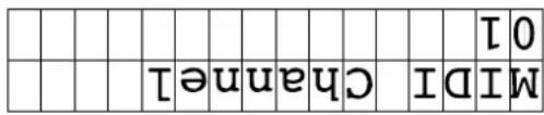
- Selecting a MIDI channel:
RS-422 interface for update-download from MACs.
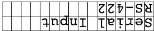
or (press Apply):
RS-232 interface for update-download from PCs
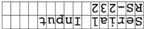
- Selecting a serial port:
No = no emphasis; YES = with emphasis
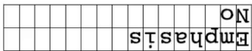
- Displaying the Emphasis Fog:
$$ \mathrm{NO} = \text { no original }; \text { YES } = \text { original } $$

- Dis playing the Original Fog:
$$ \mathrm{NO} = \text { flog eraced or not set; YES } = \text { flog set } $$

- Setting or erasing the Copy-Prohibit flag:
$$ \mathrm{NO} = \text { no error detected; YES } = \text { error detected } $$
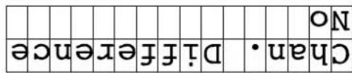
- Dis playing the Channel Difference Error Flag:
$$ \mathrm{NO} = \text { no error detected; YES } = \text { error detected } $$
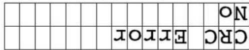
- Dis playing the CRC-Error flag:
$$ \mathrm{NO} = \text { no error detected; YES } = \text { error detected } $$

- Dis - playing the Audio-Error Fog:
The SAMPLE FREQUENCY will be detected automatically. The display either shows 44, 1 kHz, 48 kHz or 32 kHz.
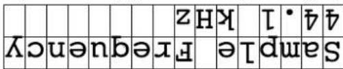
- Dis - playing the detected sample frequency:
$$ S / P - D I F \text { input without wordlock is detected } $$
| no | S | P | D | IF | WC | ||
| I | p | u | t | f | O | r | m |
or
$$ S / P - D I F \text { with wordlock detected } $$
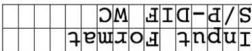
Press Apply (if S/P-DIF is detected):
no S/P-DIF input detected
| no | S | P | D | IF | |||
or:
S/P-DIF-Einging detected
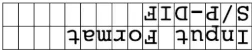
Press Apply:
AEs/EBU input without wordlock detected
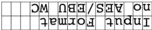
or:
AEs/EBU input with wordlock detected
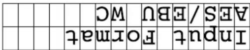
Press Apply (if AES/EBU is detected):
no AES/EBU input detected.
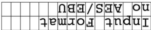
or:
AEs/EBU input detected
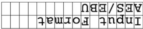
IMPORTANT: When selecting a new input allow the Sig.
LEDS to go out before stepping to the next input format. Otherwise MACHINE HEAD may lose the data stream.
to call up the INFO pages.
The MACHINE HEAD automatically searches for an input signal. If both inputs are connected the AES/EBU input will be selected first. If you want to select the S/P-DIF input you have selected first.
- Selecting inputs:
| 1. | 0 | 03/19 | 97 | ||||
| sof | tw | ware | e | ver | s | l | on |
- Software version and date
Depressing Store and Apple simultaneously for about one second gets you into a hardware dialogue, called INFO. The LC- display shows status informations of the digital data stream. With UP/Down you will jump from one page to the next or previous. If a selection is provided use Apple to select.
Operation safety: Pressets can not be changed by accident
LFD flashes. LFD grasses. LFD grasses out, preset is applied.
LFD grasses APLY gain, LFD grasses APLY gain,
preset no:
use UP/Down to select
preset no.
Applying a preset:
LED flashes. Depress Store for 1 sec. use UP/Down to select preset no.; depress Store again, LED goes out, preset is stored
Storing a preset:
Presefs
NOTE: To increase operation safety it is impossible to apply preserves by simply depressing UP or DOWN. The UP and DOWN status-LEDs will not flash indicating that the input is not accepted. You have to depress SORE or APPLY for one second in order to activate the UP and DOWN buttons.
In case you want to quit the Appley mode without applying the new preset simply press Store.
If you want to apply various presets depresses Apply for one second. The April LED starts to flash indicating that the April mode is activated. You can step through the press list with UP down. Once you have a press that you want to apply and DOWN. Once you have a press that you want to apply depresses April again. The April LED goes out indicating that the press is applied.
In case you want to quit the Store mode without storing the new adjustments simply press Appley.
new location.
If you want to store a new adjustment, depress Store for one second. The LED starts to flash indicating that the Store mode has been activated. The LC-disply now shows the values of the presses (including the Boost function) before the MACHINE HEAD was switched off the last time. Use UP and Down to select a new preset number. The status-LED flashes shortly to indicate that the input (depressing UP or DOWN) is accepted. Keeping UP then steps of 5 presses. Once a new preset location is found depressed Store again. The Store LED goes out. The preset is stored at the Store again. The Store LED goes out. The preset is stored at the
The MACHINE HEAD allows you to store up to 99 presets, within can be changed by MIDI program change command.
digital distortion.
The last LED of each Input and Output PPM meter is a CUP LED. The LED illuminates if the digital signal is too hot causing
The first LED in each Input and Output PMR meter is a signal (SIG) LED to indicate that a valid digital source is connected and detected. This LED helps you to verify the signal flow within a digit processing chain. If one SIG, LED is not illuminating you by a first indication of a faulty digital signal flow.
GAIN control (see 5).
The OUTPUT PPM meters show the peak level after the OUTPUT
The DRIVE LEVEL meterving shows the recording level of the "virtual tape machine". The display range is -10dB to +21dB. The DRIVE LEVEL is adjusted with the DRIVE control (see 3).
GAIN control (see 2).
The INPUT PPM meters show the peak level after the INPUT
tion for the last 3dB before 0dB.
The INPU and OUTPUT LED dhaps are PPM (peak level) meters with signal and clip indicators. The melting offers 1dB resol-
8 LED chains
səbəd
More information is displayed when activating the NFO pages (see 10). Press Store and Apply for 1 sec. to enter the NFO
(for details on PRESTS refer to 9).
The LC-display shows all encoder settings and the number of the preset being used in the last session with the MACHINE HEAD
7 LCDisply
Note that the 4OHZ to 7OHZ bass-reduction induced when recording to analog tape at 3OIPs is not reproduced!
resolution and finer detail.
When High Tape Speed is activated the algorithm simulates the pre-emphasis for high speed recording. The upper mid and high frequencies as well as the hormonal content gain better
speed (30ips).
With the HIGH TAPE SPEED switch you can change the speed of the virtual tape from standard tape speed (15ips) to high tape
Gaining a finer high frequency resolution when selecting High Tape Speed.
6 High Tape Speed
CLIP-LEDS.
You will set a positive Currut GAIN, when there is still headroom left after processing. Always check this on the loudest part of the audio file being processed and watch the
Also, if you have chosen a positive setting on the HF-Ajust control, it may be necessary to reduce the OUTPUT GAIN slightly in order to prevent clipping. Watch the GIP-LEDSI
You can also use the OUTPUT GAIN control to compensate for the loudness difference between unprocessed and processed signal to judge upon the sonic effect alone. After you have reduced the OUTPUT GAIN until original and processed signals have the same loudness you can recount the loudness increase on the OUTPUT PPM meters.
GAIN to complete for the slight level increase.
In practice you will start with the output Gain set to Odd. In case you have used high Drive values you will use the Output
(see 7) and in the OUTPUT PPM meter (see 8).
The adjusted OUTPUT GAIN VALUE is shown in the LC-display
OUTPUT GAIN varies the output level of the digital data stream. It is variable between -12dB and +12dB in 0.1dB steps.
Compensating a level and/or loudness increase due to processing
5 Output Gain
damping effects
Adjuditing the high frequency
HF-Adjust
On the other hand you can boost the high frequencies which simulates over-remphasized harmonics e. g. due to improper calibration of the tape machine or differences in tape quality.
machine.
The higher you saturate a red tape the more high frequency damping takes place. With the MACHINE HEAD you can set the amount of damping independent of the DRIVE LEVEL. You can either use a strong damping effect with low saturation or the other way around. This freedom is not offered by a red tape
(max. damping) to +6 (max boost).
The HF-Adjust control allows you to control the amount of high frequency damping or boosting. The control range is -6
to 0 dBFs.
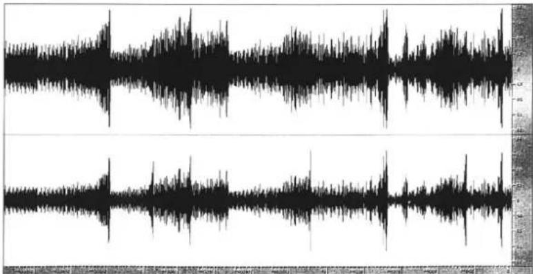
Both signals are normalized
showing increased loudness
Below: processed signal
Above: original signal
line
| Time | Value | |------|-------| | 0 | 0 | | 1 | 1 | | 2 | -1 | | 3 | 2 | | 4 | -2 | | 5 | 3 | | 6 | -3 | | 7 | 4 | | 8 | -4 | | 9 | 5 | | 10 | -5 | | 11 | 6 | | 12 | -6 | | 13 | 7 | | 14 | -7 | | 15 | 8 | | 16 | -8 | | 17 | 9 | | 18 | -9 | | 19 | 10 | | 20 | -10 | | 21 | 11 | | 22 | -11 | | 23 | 12 | | 24 | -12 | | 25 | 13 | | 26 | -13 | | 27 | 14 | | 28 | -14 | | 29 | 15 | | 30 | -15 | | 31 | 16 | | 32 | -16 | | 33 | 17 | | 34 | -17 | | 35 | 18 | | 36 | -18 | | 37 | 19 | | 38 | -19 | | 39 | 20 | | 40 | -20 | | 41 | 21 | | 42 | -21 | | 43 | 22 | | 44 | -22 | | 45 | 23 | | 46 | -23 | | 47 | 24 | | 48 | -24 | | 49 | 25 | | 50 | -25 | | 51 | 26 | | 52 | -26 | | 53 | 27 | | 54 | -27 | | 55 | 28 | | 56 | -28 | | 57 | 29 | | 58 | -29 | | 59 | 30 | | 60 | -30 | | 61 | 31 | | 62 | -31 | | 63 | 32 | | 64 | -32 | | 65 | 33 | | 66 | -33 | | 67 | 34 | | 68 | -34 | | 69 | 35 | | 70 | -35 | | 71 | 36 | | 72 | -36 | | 73 | 37 | | 74 | -37 | | 75 | 38 | | 76 | -38 | | 77 | 39 | | 78 | -39 | | 79 | 40 | | 80 | -40 | | 81 | 41 | | 82 | -41 | | 83 | 42 | | 84 | -42 | | 85 | 43 | | 86 | -43 | | 87 | 44 | | 88 | -44 | | 89 | 45 | | 90 | -45 | | 91 | 46 | | 92 | -46 | | 93 | 47 | | 94 | -47 | | 95 | 48 | | 96 | -48 | | 97 | 49 | | 98 | -49 | | 99 | 50 | | Note: The actual values may vary due to the random nature of the data generation. The provided values are just an example.meters (see 8).
The corresponding level is displayed in Drive Level PPM
When boosting the MACHINE HEAD the default value of the DRIVE parameter will be 0 in the LC-disply. If you have "the DRIVE parameter will be 0 in the LC-disply, if you have "the perfect pitch", you can already hear slight saturation effects. To keep the handling of the MACHINE HEAD as simple as possible, it is necessary to provide a 1:1 level when activating the process signals internally the MACHINE HEAD has to create a headroom - especially when processing full scale material - to compute the tape saturation algorithm. With a DRIVE set to 'true 0', you will lose 7dB headroom. As a starting position the DRIVE is there- therefore you also have negative values for the DRIVE para-meter. A true, 1:1 input/output setting is achieved by setting the DRIVE to -7 dB and the INR/TGAIN to +7 dB.
Level shown in the LED meter bar.
Recommended values are 3 to 8 for the DRIVE-parameter which corresponds with +10dB to +15dB for the actual DRIVE
The higher the Drive the more intense gets the saturation of the tape. While increasing the Drive value the output level may increase, too. Compensate for this by reducing the Output Gain value (see 5) and monitor the Output Level meters. The subje- tively the perceived loudness will increase more dramatic than
The paragraph besides offers some information on internal signal level management.
are 3 to 8.
Practical values for the Drive
The DRIVE control is the most important parameter of the MACHINE HEAD. You set the recording level above the normal values range from -7 to +14 in 0.2dB steps and will be shown in the LC-disply (see 7). The corresponding recording level is displayed by the DRIVE LEVEL-LED bars (see 8).
Setting the recording level of the virtual tape machine,

Drive
proviso of the INPU-T-CUP LEDS (see 8). In practise you will start with the Input GAIN set to OdB. For most applications this is the appropriate setting. If your source material is of very low level or not normalized yet, you can use the Input GAIN control to drive the source material near full scale. If you are processing full scale material it may be necessary to reduce the input signal by one or two dbs to create new headroom for the processing. Reduce the Input GAIN with the
control.
INPUT GAIN adjusts the input level of the digital data stream. Adjustable values range from -12.0dB to +12.0dB in 0.1dB steps. The value is shown in the LC-disply (see 6) and the NUT PPM meters displays the actual input level after the InputT GAIN

Input Gain
The AES/EBU input and output are equipped with relay-hard-bypass. In the event of a power failure the MACHINE HEAD is automatically switched to hard-bypass (power failure safety) without interpreting the data flow.
The software bypass also competes for the 5ms time delay between processed and unprocessed signals.
activated.
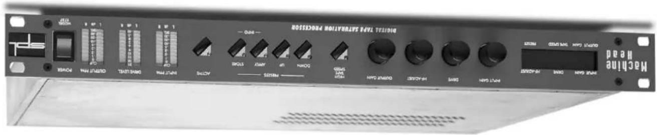
The Active function switches the MACHINE HEAD on or off. The illuminated LED indicates that the processing has been
Relay hard-bypass for AFES/EBU input and output

Active
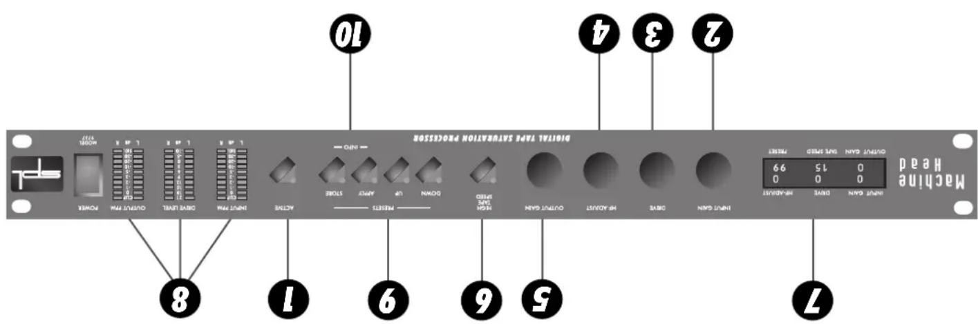
Control Elements
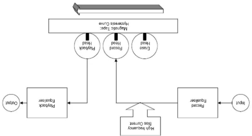
The playback head converts the magnetic field of the passing tape back into current and voltage. The playback evaluator has a nommed frequency response (e.g. CIR/NAB) which makes the overall frequency response flat and constantes for the additional boost in the recording evaluator.
The recording head converts the current of the input signal into a magnetic field. The field magnetizes the magnetic particles on the passing tape. This process is physically complex and non-linear. Hysterisks curves lead to the typical saturation effect and to the effect of short wavelength losses.
magnetization.
A high frequency bias current is afterwards added to the signal to linearize the non-linear hysteresis transfer curve of the
improve the signal to noise ratio.
The audio signal that passes the input electronics of an analogue tape machine is first processed by the recording equalizer. The high frequencies are boosted to compensate for the level loss of those frequencies during magnetization and to
Recording Signal Flow Analogue Tape
flowchart
graph TD
    A["Input"] --> B["Record Equalizer"]
    B --> C["High frequency bus Current"]
    C --> D["Output"]
    D --> E["Forward Head"]
    E --> F["Flash Equalizer"]
    F --> G["Forward Head"]
    G --> H["Flash Equalizer"]
    H --> I["Magnetic Tape: Hydreads Quave"]
    I --> J["Flash Equalizer"]
    J --> K["Flash Equalizer"]
    K --> L["Flash Equalizer"]
    L --> M["Flash Equalizer"]
    M --> N["Flash Equalizer"]
    N --> O["Flash Equalizer"]
    O --> P["Flash Equalizer"]
    P --> Q["Flash Equalizer"]
    Q --> R["Flash Equalizer"]
    R --> S["Flash Equalizer"]
    S --> T["Flash Equalizer"]
    T --> U["Flash Equalizer"]
    U --> V["Flash Equalizer"]
    V --> W["Flash Equalizer"]
    W --> X["Flash Equalizer"]
    X --> Y["Flash Equalizer"]
    Y --> Z["Flash Equalizer"]
    Z --> AA["Flash Equalizer"]
    AA --> AB["Flash Equalizer"]
    AB --> AC["Flash Equalizer"]
    AC --> AD["Flash Equalizer"]
    AD --> AE["Flash Equalizer"]
    AE --> AF["Flash Equalizer"]
    AF --> AG["Flash Equalizer"]
    AG --> AH["Flash Equalizer"]
    AH --> AI["Flash Equalizer"]
    AI --> AJ["Flash Equalizer"]
    AJ --> AK["Flash Equalizer"]
    AK --> AL["Flash Equalizer"]
    AL --> AM["Flash Equalizer"]
    AM --> AN["Flash Equalizer"]
    AN --> AO["Flash Equalizer"]
    AO --> AP["Flash Equalizer"]
    AP --> AQ["Flash Equalizer"]
    AQ --> AR["Flash Equalizer"]
    AR --> AS["Flash Equalizer"]
    AS --> AT["Flash Equalizer"]
    AT --> AU["Flash Equalizer"]
    AU --> AV["Flash Equalizer"]
    AV --> AW["Flash Equalizer"]
    AW --> AX["Flash Equalizer"]
    AX --> AY["Flash Equalizer"]
values).
-
Use the HF-A. Djust control to create the typical high frequency damping effect (negative values) or increase the high frequencies and harmonic control (positive
-
If more saturation is wanted, it may be necessary to reduce the Input Gain slightly to prevent dripping.
-
Increase the value to saturate the "virtual" tape. Set Drive to about 6. If the output level increases, use the OUTPUT GAIN control to complete for the increase.
-
Press Active LED illuminates.
-
If an error occurred during download the LC-disply says "download failed", The MACHINE HEAD now waits for a new download. Please check all adjustments on your terminal program and try again. If you are still un-successful contact your local dealer.
-
Switch the MACHINE HEAD off and on after 4 sec. The new software version number is displayed in the first INFO page (simultaneously depress Store and APUy); also refer to CONTROL ELEMENTS No. 9, INFO).
-
Load the update file into your terminal program and send it to the MACHINE HEAD. The LC- display shows the progress of the download in KB. 5. After successfully installing the new software version the LC-display says "download valid".
-
Switch on the M ACINE HEAD and depress both Préset UP and Préset DOWN until the LC-display suggests „wait for Zmodem download“.
-
Open a terminal program like "Hypermindal" on PC and make the following adjustments: Baud rate: 9600; Stop bit: 1; Parity: none; Data bit: 8; Handshake: no; Transfer mode: ZMODEM
-
Connect your computer with the MACHINE HEAD via a serial port with a standard Z-modem cable. RS-232 for PC and RS-422 for MAC.
Note: All presets will be lost after installing a new software version!
Installing Updates:
For easy upgrade of future software releases, the rear panel offers RS-232 interface for PC and RS-422 interface for MAC.
MIDI IN and MIDI THROUGH connectors allow presets to be selected via MIDI program change commands.
termination.
Through BNC connectors are fitted with a switchable 75 Ohm For synchronization purposes Woodlock In and Woodlock
the input resolution.
The MACHINE HEAD operates with 24 bit word width, it accepts 16 to 24 bit inputs and will create output signals according to
some time if required.
The rear panel provides AES/EBU- and S/P-DIF-inputs and outputs. Any additional channel, status and user-bits are passed through unaltered, and the outputs can be used at the
all connected units.
Before connecting the MACHINE HEAD switch the power off at

Operation Safety
software
User-friendly programmed
„Analogue „control feeling
time operation
power guaranteeing real-
Enormous computational
The DSP Platform:
level
DRIVE-LED displays recording
PPM meeting
Input and Output
Clip-LEDS
streetam
Signal-LEDs to verify data
Only clean your MACHINE HEAD with a soft, lint-free cloth.
Never cover up the ventilation slots on the top of the unit. If, during operation, the sound is interpreted or indicators no longer illuminate, or if abnormal odor or smoke is detected, or if liquids are spilled on the unit, immediately disconnect the power cord plug and contact your dealer.
Check that the voltage details quoted on the back panel are the same as your local mains electricity supply. Use a minus (-) screwdriver to set the voltage selector to the voltage for the area in which the unit will be used.
The MACHINE HEAD should not be installed near units which produce strong magnetic fields or extreme heat. Do not install the MACHINE HEAD directly above or below power amplifiers.
support, especially in a turning case.
The housing of the MACHINE HEAD has the standard 19-. ELA format and occupies 1U (44.45 mm) in your rack. When installed by the unit in a 19"-rack, the rear side of the unit needs some ring the unit in a 19"-rack, the rear side of the unit needs some ring the unit in a 19"-rack, the rear side of the unit needs some ring the unit in a 19"-rack, the rear side of the unit needs some ring the unit in a 19"-rack, the rear side of the unit needs some ring the unit in a 19"-rack, the rear side of the unit needs some ring the unit in a
parameters.
The philosophy behind the digital audio processors is that they are designed to be operated like analogue units; there is only one INFO menu but no multi-function controls. The LCD readout simply shows the current encoder positions and the preset number. The encoders are built without clicks or detents, so they feel like analogue pots. Our DSP platform uses two computational power guarantees real-time operation where sophisticated DSP algorithms will not be restricted by resource limitations. The general concept is that each digital processor should fulfill only one task, in the most effective way possible, and with a minimum of controls and switches. As much as possible should be automated to promote user-friendly operator - the external controls access only the socially relevant
to +21dB.
The D River LED chips display the drive or recording level that is sent to the virtual tape. The values shown range from -10dB
also be shown on the OUTPUT PPM claims.
The top LEDs of each input and output meter indicate if a digital clip has occurred at the inputs or due to processing within MACHINE HEAD. Clipping that is already present at the inputs will
data steam is interpreted or invalid.
MACHINE HEAD is equipped with PPM displays for input and output levels. The first LED of each input and output meter is a signal (SIG.) LED which illuminates when a compatible digital data stream is present at the inputs. The LEDs are a first indicator to check the data stream. If the LEDs do not illuminate the data stream is present at the inputs. The LEDs are a first indicator to check the data stream. If the LEDs do not illuminate the data stream is present at the inputs. The LEDs are a first indicator to check the data stream.
Indicators and meters:
high tape speed (30ips).
High Tape Speed: Switches from normal tape speed (15ips) to
stream
OUTPUT GAIN: Controls the output level of the digital data
damping
HF-Adjust: Controls the intensity of high frequency boost or
„virtual analogue tape machine"
Drive: Controls the drive or recording level of the
stream
INPUT GAIN: Controls the input level of the digital data
one switch function:
Operation: MACHINE HEAD is operated with four controls and
Easy and intuitive operation
institcs of analogue tape machinesi;
In fact MACHINE HEAD provides all the benefits of analogue recording without any of the shortfalls – MACHINE HEAD does not reproduce cross-talk, pre or post echoes, noise floor (field noise, modulation noise) and motor speed fluctuation chargeate-
damping at all.
The level behavior and high frequency damping is repro- duced in a modified manner. To achieve the best possible signal to noise ratio, an auto gain cell has been implemented into the alGORITHM in order to create a processing range for saturation effects for full scale input signals and to deliver full scale output signals afterwards. The intensity of high frequency damping varies from one tape to another, and is therefore fully adju- stable one the MACHINE HEAD. It is now also possible to make use of extreme saturation effects without high frequency
ding to analogue tape.
The algorithm used by Machine Head precisely reproduces the analogous tape saturation effect, including hysteresis effects, the harmonic characteristic and both linear and non-linear trans-mission-characteristic (other than level) that occur when recor-
mixes.
MACHINE HEAD is designed for mastering applications. Mixes gain more power, punch and warmth. It is also suited to process single instruments, like electronic or acoustic guitars and bases, dumps, loops and samples, as well as complete stereo
The subjective sonic effects are an increase in loudness and a better penetration of the mix at identical peak level. The sound becomes warmer and more powerful, and the process elims-
digital domain.
Concept: The algorithm used by MACHINE HEAD computes arithmetic tape saturation effects, hitherto unavailable in the
within SPL's Digital-Red series.
The MACHINE HEAD is a creative sound and dynamics processor
- motor speed fluctuation
- noise floor
- pre or post echoes
- CROSS-tALK
Not reproduced are:
-high frequency damping
- level behavior
Modified reproduction of:
mission characteristic
- harmonic characteristic
- hysteresis effect
- tape saturation effect
Precise reproduction of:
recordings.
tiring the harnesses of digital
and more powerful, elima-
The sound becomes warmer
saturation effects.
Creating authentic tape
Hermann Gier
Our products are often tested and compared in many public-
mated.
I would like to start with my thanks to all our staff, who created what is to be described here. Special thanks go to Kai I have been created from Lukas & Hartmann Soundart, Jörg Hooper and Kluas-Peter Webersinke from Spectral Design as well as Harold Oboenland from Octumn electronics. The importance of their exceptional qualification and talents cannot be overesti-
Thanks
Your SOUND PERFORMANCE LAB-Team
We wish you every success with the MACHINE HEAD.
MACCHINE HEAD.
As a typical SPL unit the MACHINE HEAD combines exemplary specifications and high manufacturing standard with excellent sound quality to provide you a precious component for studio and mastering purposes. Please read this manual carefully to ensure you have all the information you need to use the
Thank you for the confidence you have shown towards SPL electronics Gmbh by purdising the SPL MACHINE HEAD. You have decided to use a tool of high performance which sets you in the position to have faster success and a better sound quality in your music productions, pre-masterings and masterings.
Dear customer,
Foreword
| Forward 3 | Thousands 3 |
| Introduction 4 | Operation Safety 5 |
| Connections 6 | Connections 6 |
| Installing Updates 6 | Quick Start 7 |
| Analogue Tape Recording Signal Flow | 7 |
| Control Elements | 8 |
| Active | 8 |
| Interrupt GAIN 8 | 9 |
| Drive | 8 |
| High Tape Speed | 10 |
| LC-Display | 10 |
| LED CHAINS | 10 |
| Presets | 11 |
| INFO (Hardware Dialogue) | 11 |
| Warranty | 16 |
| Specifications | 15 |
wwv.spl-electronics.com
Malit: info@spI-electronics.com
Fax: +49 - 21 63 / 98 34 20
Phone: +49 - 21 63 / 9 83 40
D-41368 Niederkurechten, Germany
P.O. Box 1227
SPL electronics GmbH
possibility of such damage.
In no event will SPL be liable for any damages, including loss of data, lost profits, cost of cover or other special, incidental, consequential or indirect damages arising from the use of the unit, however caused and on any theory of liable- itv. This limitation will apply even if SPL or an authorized dealer has been advised of the
Limitations of Liability:
inflation of SPl.
The information in this document has been carefully verified and is assumed to be correct. However Sound Performance Laboratory (SPL) reserves the right to modify the product described in this manual at any time. Changes without notice. This document is the property of any manner, in part or full without the author-
Version 1.3-1/1999
by Hermann Gier
Manual
MODEL 9737
MACCHINE HEAD
SOUND PERFORMANCE LAB

Digital Tape Saturation Processor
Model 9737
Macchine Head
Manuel

SOUND PERFORMANCE LAB
- MACHINE HEAD MODELL 9737
- Bedienungsanleitung
- Messungen
- www.SPL-electronics.com
- MIDI IMPLEMENTATIONS
- Presefs
- LED chains
- LCDisply
- High Tape Speed
- Output Gain
- HF-Adjust
- Recording Signal Flow Analogue Tape
- Installing Updates:
- Operation Safety
- Hermann Gier
- Thanks
- Your SOUND PERFORMANCE LAB-Team
- Foreword
- Macchine Head
Brand : SPL
Model : Machine Head 9737
Category : Uncategorized