MPR-60S-41 - Analyseur réseau ENTES - Free user manual and instructions
Find the device manual for free MPR-60S-41 ENTES in PDF.


| Type de produit | Analyseur de réseau électrique |
| Marque | ENTES |
| Modèle | MPR-60S-41 |
| Dimensions (L x H x P) | 96 x 96 x Profondeur (non spécifiée) |
| Poids | 0.75 kg |
| Alimentation | Voir étiquette sur l’appareil (typ. 100-240 V AC) |
| Consommation | < 6 VA |
| Affichage | Écran LCD 3,6 pouces avec rétroéclairage |
| Entrées de mesure | Tension L-N : 1-300 V AC, L-L : 2-500 V AC ; Courant : 0,005-5,5 A |
| Précision | Tension/Courant : 0,5 % ± 2 digit ; Puissance active : 1 % ± 2 digit |
| Communication | RS-485 Modbus RTU (1200-38400 bps) |
| Sorties relais | 2 x NO, 5 A, 1250 VA |
| Sorties impulsion énergie | 2 sorties (active et réactive) jusqu'à 50 mA, 5-30 V DC |
| Entrées numériques | 2 entrées (5-24 V DC, max 30 V DC) |
| Sortie analogique | 0-20 mA ou 4-20 mA (MPR60S-41) |
| Mémoire interne | 1 MB (jusqu'à 15 000 enregistrements de 28 paramètres) |
| Protection | IP40 (face avant), double isolation classe II |
| Température de fonctionnement | -5°C à +50°C |
| Normes | EN 61000-6-2, EN 61000-6-4, EN 61010-1, etc. |
| Entretien et nettoyage | Déconnecter l’alimentation, nettoyer avec un chiffon humide (pas de solvant) |
| Sécurité | Consulter la notice avant installation ; réservé au personnel qualifié |
| Pièces détachées et réparabilité | Contacter le fabricant ou un technicien agréé |
Frequently Asked Questions - MPR-60S-41 ENTES
User questions about MPR-60S-41 ENTES
0 question about this device. Answer the ones you know or ask your own.
Ask a new question about this device
Download the instructions for your Analyseur réseau in PDF format for free! Find your manual MPR-60S-41 - ENTES and take your electronic device back in hand. On this page are published all the documents necessary for the use of your device. MPR-60S-41 by ENTES.
USER MANUAL MPR-60S-41 ENTES
ATTENTION : Consult the operating instructions before using the equipment.
If these precautions are not properly observed and carried out, it can cause physical accident or damage to the equipment or the installation.
The manufacturer or the authorized seller is not responsible for the consequences resulting from failure to comply with these precautions.
SAFETY PRECAUTIONS
This equipment has been manufactured and tested and it has left the factory in perfectly safe condition. To preserve this and ensure safe operation of the equipment the user should comply with the instruction which are mentioned in this manual.
Before installing, check that the operating and network voltages are the same!
Before carrying out any work on the equipment, check that it is disconnected from the electrical supply.
If the equipment is no longer completely safe to use, it should be taken out of service and protected against any accidental use.
Operator Safety
Read the following recommendations carefully before installing and operating the equipment.
The equipment described in this manual is designed only to be used by trained personnel.
Maintenance work must be carried out only by qualified, authorised personnel.
Personnel must observe the usual safety procedures for safe operation and during any maintenance work.
Breakdown Precautions
If you suspect that the equipment may no longer be safe (e.g. because of transport or operational damage), it must be taken out of service and protected against any accidental use.
The equipment should be handed over to authorised technicians for checking.
Cleaning Instructions
Disconnect the equipment from the electrical supply and only use a damp cloth to clean the external surfaces. Do not use any abrasive materials or solvents. Do not allow any moisture to reach the connection terminals.
Standards which are applied to the device:
EN 61000-6-2, EN 61000-6-4, EN 55016-2-1, EN 55016-2-3, EN 55011, EN 61000-3-2, EN 61000-3-3, EN 61010-1
EN 61000-4-2, EN 61000-4-3, EN 61000-4-4, EN 61000-4-5, EN 61000-4-6, EN 61000-4-8, EN 61000-4-11
Important note for system connection
①②③ indicators indicate the existence of the three phases. (See Figure 1)
If indicator (Phase sequence is not correct) is seen, you have to change any of the 2 phases before proceeding. (L1 - L2, L2 - L3 or L1 - L3)
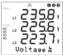
Figure 1: The existence of three phases on LCD.
SUMMARY
SAFETY PRECAUTIONS....1 IMPORTANT NOTE FOR SYSTEM CONNECTION....1
1. DESCRIPTION....3
1.1 Introduction....3
1.2 The front panel 4
1.3 Front panel properties....5
1.4 The rear panel....6
2. INSTALLATION 7
2.1 Mechanical assembly....7
2.2 Operating conditions....7
2.3 Electrical connection....8
2.4 PC Connection....9
3. MODBUS RTU PROTOCOL 10
3.1 Modbus functions....10
3.2 Features of connection cable....11
3.3 I/O Relay Status Register....11
3.4 Learning of device informations(2BH)....11
3.5 Reading and writing to data logs from device (14H)....11
3.6 File record information table....11
3.7 Energy log table....12
3.8 Error codes....12
3.9 MPR-SW (Interface Program)....12
3.10 Data register map (16 bit)....13
3.11 Data register map (32 bit)....14
3.12 Setup register map (16 bit) (MPR60S) 15
3.13 Setup register map (16 bit) (MPR60S -10) 16
3.14 Setup register map (16 bit) (MPR60S -20) 17
3.15 Setup register map (16 bit) (MPR60S -21) 18
3.16 Setup register map (16 bit) (MPR60S -40) 19
3.17 Setup register map (16 bit) (MPR60S-41) 20
4. GENERAL MENU 21
4.1 Setup....21
4.2 Network....21
4.3 Setting the date and time....22
4.4 PC Communication Settings (RS-485)....22
4.5 Datalog....23
4.6 Output Relays and Digital Outputs (Relay 1 and Relay 2)....24
4.7 Pulse Outputs (Pulse A and Pulse R) (MPR60S/MPR60S -21/41) 27
4.8 Digital Inputs (3. Input-1 / 4. Input-2) (MPR60S-10/20/40) 29
4.9 Display 30
4.10 Instantaneous Values....30
4.11 Energy....33
4.12 Demand 35
4.13 Observing the time and date....38
4.14 Info....40
4.15 Manufacturer-Product Information 41
4.16 Password....42
4.17 Parameter Table 43
4.18 Formulas....43
4.19 Current Analog Output (0/4-20mA) (MPR60S -40/41) 44
4.20 Voltage Analog Output (0/2-10V) (MPR60S-20/21) 45
4.21 Factory Settings....46
4.22 Technical Data 47
5. STANDART AND EXPLANATIONS......48
1. DESCRIPTION
1.1 INTRODUCTION
Device is a network analyser in 96x96 mm dimension with a non-flammable enclosure. It is designed for measuring all electrical parameters of an electric network with MODBUS-RTU Protocol on RS-485 communication port in order to communicate with the computer.
Device, based on DSP (Digital Signal Processor), is designed for the purpose of measuring all parameters in industry plants and recording these parameters to its memory. The measured parameters can be displayed on LCD screen which has dimension of 3.6 inch and can be read easily in dark environments by activating the Back-Light function.
Device contains a MODBUS serial interface option.

Figure 2: General view of the device.
MPR60S Network Analyser





Figure 3: Display and buttons.
Four buttons provide access to programming and measurement screens. The display is LCD and has a white backlight.
KEY FUNCTIONS
| BUTTON | FUNCTION |
| ESC | Exit from a menu any time (THD I and THD V can also be displayed) |
| Go to next menu or increase related value | |
| Go to the previous menu or decrease related value | |
| Enter to a menu or confirm the data entry |
1.3 DISPLAY

1 ...... Menu (ENTER) button.
2 ...... Down button.
3 ...... Up button.
4 ...... ESC button. Exits from a menu or settings at any time. (THD I, THD V can also be displayed)
5 ...... Menu / Energy line : Shows the present menu. / It also shows the energy values.
6 ...... Shows whether the value in the Energy Menu is Export, Import, Inductive or capacitive.
7 ...... Active output is indicated.
8 ...... Harmonic bars: The total harmonics of the 3 phases are displayed in bar graphs. The columns represent L1, L2 and L3 phases. Each step indicate 10% increase / decrease V is for the voltages harmonics and I is for the currents harmonics.
9 ..... Indicates if the measure is phase to phase or phase to neutral.
10..... The Cosφ or PF (Power Factor) value of the related phase.
11 ..... Indicates if the measurement is capacitive or inductive.
12 ...... Min. and Max. symbols for the demand menu.
13 ..... Indicates that the harmonics are displayed on the screen.
14 .... Total symbol. Shows the total value of the related measurement.
15 ...... Phase sequence failure
16 .... Demand symbol. Shows the demand value of the related parameter.
17 ...... PC Communication indicator.
18 ...... Phase indication symbols.
19 ..... Shows the following measurement values with units. (V, kV, MV, A, kA, MA, W, kW, MW, VA, kVA, MVA, VAr, kVAr, MVAr %)
20 ..... 3.6" LCD Display.
21 ...... Backlight.
22 ..... Shows the unit of energy values. (kWh, kVArh, MWh, MVArh)
1.4 THE REAR PANEL

MPR60S

MPR60S-10

MPR60S-21/41

MPR60S-20/40
Figure 4: The terminals on the rear panel.




Current monitoring terminals
Voltage monitoring terminals
Analog output / RS-485 output (Only for MPR60S-20/21/40/41)
RS-485 output
Digital output / Alarm
Energy pulse outputs (Only for MPR60S / MPR60S-21/41)
Digital inputs (Only for MPR60S-10/20/40)
Auxiliary supply terminals
2. INSTALLATION
2.1 MECHANICAL ASSEMBLY
The following drawings are the overall dimensions for the device and the panel cut-out.

Figure 5: Dimension and the panel cut-out.
2.2 OPERATING CONDITIONS
CLIMATIC ENVIRONMENT
The device should be protected from water / dense moisture and be installed in a covered enclosure when used in a dusty environment. Ambient operating temperature is between -5^ and +50^
ELECTRICAL ENVIRONMENT
Although the device is protected against electrical current fluctuations, it is advisable to avoid the immediate proximity of equipment generating heavy drains (high power contactors, sets of busbars, etc.) The quality of communication obtained from the computer bus depends to a large extent on observing these precautions.
2.3 ELECTRICAL CONNECTION
Wire thickness for voltage terminals must be 2.5 mm^2 and 4.0 mm^2 for current terminals. For energy pulse outputs and digital inputs the required wire thickness is 1.5 mm^2 .
The fuse must be Type FF with 1A current limit.

Figure 6: 3 phase with neutral connection

Figure 7: 3 phase without neutral connection

Figure 8: ARON connection (3 phase without neutral connection)
2.4 PC CONNECTION
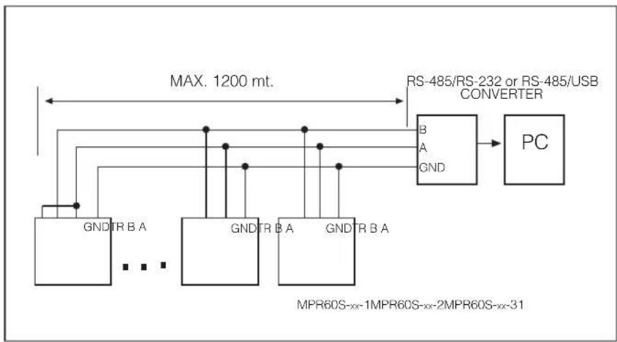
RS 485/232 Converter is necessary for communicating with computer.
flowchart
graph TD
    A["Max. 1200 mt."] --> B["RS-485/RS-232 or RS-485/USB CONVERTER"]
    B --> C["PC"]
    D["GNDTR B A"] --> E["GNDTR B A"]
    F["GNDTR B A"] --> G["GNDTR B A"]
    H["GNDTR B A"] --> I["GNDTR B A"]
    J["B A"] --> K["GND"]
    L["B A"] --> M["GND"]
    N["..."] --> O["..."]
    P["MPR60S-xx-1MPR60S-xx-2MPR60S-xx-31"]
Figure 9: 31 devices can be connected to the same line.
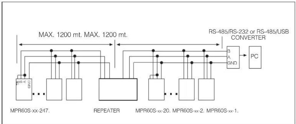
After 20 pieces of device, a repeater is advised for amplifying the data signal.
flowchart
graph TD
    A["MPR60S-xx-247."] --> B["REPEATER"]
    B --> C["PC"]
    D["RS-485/RS-232 or RS-485/USB CONVERTER"] --> E["PC"]
    F["Max. 1200 mt. MAX. 1200 mt."] --> G["PC"]
    H["Max. 1200 mt."] --> I["PC"]
    J["Max. 1200 mt."] --> K["PC"]
    L["Max. 1200 mt."] --> M["PC"]
    N["Max. 1200 mt."] --> O["PC"]
    P["Max. 1200 mt."] --> Q["PC"]
    R["Max. 1200 mt."] --> S["PC"]
    T["Max. 1200 mt."] --> U["PC"]
    V["Max. 1200 mt."] --> W["PC"]
    X["Max. 1200 mt."] --> Y["PC"]
    Z["Max. 1200 mt."] --> AA["PC"]
Figure 10: By using repeaters, 247 devices can be connected to the same line.
3. MODBUS RTU PROTOCOL
MODBUS RTU PROTOCOL
Standard message format of MODBUS RTU is as below :
| T | ADDRESS8 BITS | FUNCTION8 BITS | DATAN x 8 BITS | CRCH CRCL T |
Starting and finishing of T times, which are as much as 3.5 characters time, are time periods of data lines which must be constant for evaluating by devices at the line if the message starts or finishes.
Address area, which is between 1 and 247, shows the serial address of device at the line.
Data area contains the data which is sent to device from slave to master or from master to slave.
CRC is a determination methode of error which is used at the MODBUS RTU Protocol and it has 2 bytes
3.1 Modbus Functions:
| 03H REGISTER READING | 14H LOG DATA RECORD READING |
| 06H SINGLE REGISTER WRITING | 2BH DEVICE INFORMATION READING |
| 10H MULTIPLE REGISTER WRITING |
Register Reading (03H) function is used to read measured parameters and transformer ratios. If a register is tried to read except for values, device sends error message.
Example : This message must be sent to the device for reading the phase-neutral voltage of Phase 1;
01 Device address
03 Function
00 MSB address
00 LSB address
00 Register numbers MSB
01 Register numbers LSB
84 CRC MSB
0A CRC LSB
Single register writing command (06) is used to set the transformer ratios or clear any of min., max. or demand values. Current transformer ratio can be entered between 1 and 5000 and voltage transformer ratio can be entered between 1 and 4000. Only "0" (zero) value can be entered to the demand values.
For setting the CT ratio as 100;
01 Device address
06 Function
01 MSB address
00 LSB address
00 Data MSB
64 Data LSB
89 CRC MSB
DD CRC LSB
Multiple register writing command (10H) is used to change more than one register value. For setting the CT ratio as 100 and voltage transformer ratio as 2;
RESPONSE
01 Device address 01 Device address
10 Function 10 Function
01 MSB address 01 Register address (high)
00 LSB address 00 Register address (low)
00 Register number MSB 00 Number of registers (high)
02 Register number LSB 02 Number of registers (low)
04 Byte number 40 CRC (high)
00 Data MSB 34 CRC (low)
64 Data LSB
00 Data MSB
C8 Data LSB
BE CRC MSB
76 CRC LSB
Parameters are transmitted as 16 bit hexadecimal.
For example
- 230,6 V voltage value of the device is received as 2306 (0902H) and real value is obtained by multiplying to its multiplier (x0,1) and VT ratio
● 1,907A current value is received as 1907 (0773H) and it is multiplied by 0,001 and CT ratio
- -0,78 P.F. value is received as FCF4H. (16 bit signed integer)
● Energy values are sent as 2 words in 16 bit register table.
Energy value = (High x 10.000) + Low
Example
Low High
06237819 kWh = 1E8BH 026FH
3.2 Features of connection cable:
- Screened
- 24 AWG or more thickness
- DC resistance : =<100 ohm/km
- Characteristic impedance : 100 ohm for 100kHz
- Capacitor between two conductors : =< 60 pF/m
- Capacitor between one conductor and earth : =< 120 pF/m
3.3 I/O Relay Status Register.
I/O Relay Status register is used to observe the status of device outputs
| 15 | 14 | 13 | 12 | 11 | 10 | 9 | 8 | 7 | 6 | 5 | 4 | 3 | 2 | 1 | 0 |
| 0 | 0 | 0 | 0 | 0 | 0 | 0 | 0 | 0 | 0 | 0 | 0 | 0 | 0 | Relay2 | Relay1 |
| 131415 | 12 | 11 | 910 | 8 | 7 | 6 | 5 | 4 | 3 | 12 | 0 | ||||||||||||
| 0 | 0 | 0 | 0 | 0 | 0 | 0 | 0 | 0 | 0 | 0 | 0 | 0 | 0 | 0 | 0 | Input2 | Input1 | Relay2 | Relay1 | (Only for MPR60S-10/20/40) | |||
- When Relay 1 is switched on, 0 (zero) bit of I/O Relay Status Register is read as 1 and when Relay 1 is not switched on it is read as 0.
- When Relay 2 is switched on, 1st bit of I/O Relay Status Register is read as 1 and when Relay 2 is not switched on it is read as 0.
- If Relay Functions (Setup register:011AH/012DH) is set to "1" then Relay 1/2 functions as "Digital Output 1/2".
For switch ON Relay 1 Example : 01 06 00 4C 00 01 CRC
For switch ON Relay 2 Example : 01 06 00 4C 00 02 CRC
For switch ON both relays Example : 01 06 00 4C 00 03 CRC
For switch OFF both relays Example : 01 06 00 4C 00 00 CRC
3.4 Learning of device informations (2BH)
Following data packet is sent to device to learn the device code, program version, manufacturer name and manufacturer web site :
01 2B 0E 01 00 70 77
3.5 Reading and writing to data logs from device (14H)
Modbus RTU 14H function is used to transmit measured parameters to the computer, when the device is not connected with computer.
01 14 07 06 00 00 00 02 00 01 99 24
| 01 Device address | |
| 14 Function | |
| 07 Byte number | |
| 06 Reference type | |
| 00 File number MSB | 0-15 |
| 00 File number LSB | |
| 00 Record number MSB | 0-999 |
| 02 Record number LSB | |
| 00 Record length MSB | 1 |
| 01 Record length LSB | |
| 99 CRC MSB | |
| 24 CRC LSB | |
Answer
| 01 | Device address |
| 14 | Function |
| 46 | Data length |
| 20 | Record length |
| 06 | Reference type |
| 00 | Record number MSB |
| 02 | Record number LSB |
| 02 | Record date Day |
| 10 | Record date Month |
| 05 | Record date Year |
| 19 | Record date Hour |
| 07 | Record date Minute |
| 23 | Record date Second |
| 08 | Data 01 MSB |
| BC | Data 01 LSB |
| 08 | Data 02 MSB |
| 95 | Data 02 LSB |
| : | : : : : |
| 00 | Data 28 MSB |
| 00 | Data 28 LSB |
| 71 | CRC MSB |
| B0 | CRC LSB |

Warning : Data logs must be deleted individually for each file.
For deleting the data logs at the File 0, below request must be sent.
Request: 01 06 04 01 00 00 D9 3A
Response : 01 06 04 01 00 00 D9 3A
record numbers
* Please refer to page 12 for energy log table.
| Log format | Type | Range | |
| 1 | Index Hi | Word | 0..999 |
| Index Lo | |||
| 2 | Day Hi | Word | 1..31 |
| Month Lo | 1..12 | ||
| 3 | Year Hi | Word | 00.99 |
| Hour Lo | 00..23 | ||
| 4 | Minute Hi | Word | 00..59 |
| Second Lo | 00..59 | ||
| 5 | Data 01 Hi | Word | 0..65535 |
| Data 01 Lo | |||
| 6 | Data 02 Hi | Word | 0..65535 |
| Data 02 Lo | |||
| ⋮ | ⋮ | ||
| 31 | Data 28 Hi | Word | 0..65535 |
| Data 28 Lo | |||
| 32 | CRC | Word | CRC16 |
3.6 File Record Information Table
It shows the number of records, open file and total number of recordings of the files which have data logs.
| ADDRESS | DESCRIPTION DIMENSION | |
| 0400H | File which is recorded now. (0-14) | word |
| 0401H | Record numbers at File 0 | word |
| 0402H | Record numbers at File 1 | word |
| ⋮ | ⋮ | ⋮ |
| 0410H | Record numbers at energy file | word |
| 0411H | Total record numbers | word |
3.7 Energy Log
| Index | Energy Log Format Dimension Multiplier Range Unit | ||||
| 1 Index Word 0..999 - | Data | ||||
| 2 | Day(Hi) 1..31 | Word | Data | d | |
| Month(Lo) 1..12 | m | ||||
| 3 | Year(Hi) 00..99 | Word | Data | y | |
| Hour (Lo) 00..23 | h | ||||
| 4 | Minute(Hi) 00..59 | Word | Data | m | |
| Second (Lo) 00..59 | s | ||||
| 5 | Import Active Energy(Lo) | Word | Data | - | kWh/MWh |
| 6 | Import Active Energy(Hi) | Word | Data x 10000 | 99999999 | |
| 7 | Export Active Energy (Lo) | Word | Data | - | kWh/MWh |
| 8 | Export Active Energy(Hi) | Word | Data x 10000 | 99999999 | |
| 9 | Inductive Reactive Energy(Lo) | Word | Data | - | kVArh/MVArh |
| 10 | Inductive Reactive Energy(Hi) | Word | Data x 10000 | 99999999 | |
| 11 | Capacitive Reactive Energy(Lo) | Word | Data | - | kVArh/MVArh |
| 12 | Capacitive Reactive Energy(Hi) | Word | Data x 10000 | 99999999 | |
| 13 | Voltage High LN1 | Word | Data x VT x 0.1 | 0...Vmax | V |
| 14 | Voltage High LN2 Word 0...Vmax | V | Data x VT x 0.1 | ||
| 15 | Voltage High LN3 Word 0...Vmax | V | Data x VT x 0.1 | ||
| 16 | Current High Demand L1 | Word | Data x CT x 0.001 | 0...Imax | A |
| 17 | Current High Demand L2 | Word 0...Imax | Data ACT x 0.001 | ||
| 18 | Current High Demand L3 | Word 0...Imax | Data ACT x 0.001 | ||
| 19 | Current Demand L1 | Word | Data x CT x 0.001 | 0...Imax | A |
| 20 | Current Demand L2 | Word 0...Imax | Data ACT x 0.001 | ||
| 21 | Current Demand L3 | Word 0...Imax | Data ACT x 0.001 | ||
| 22 | Total Curent High Demand | Word | Data x CT x 0.001 | 0...Imax | A |
| 23 | Energy Counter Unit | Word | Data | 0:Kilo/1:Mega | - |
| 24 | Total Current Demand | Word 0...Imax | Data ACT x 0.001 | ||
| 25 | Total Active Power Demand | Signed Word | Data x VT x CT | 0..±Ptmax | W |
| 26 | Total Reactive Power Demand | Signed Word | Data x VT x CT | 0..±Qtmax | VAr |
| 27 | Total Appearnt Power Demand | Word 0..Stmax | Data x VT x CT | VA | |
| 28 | Frequency | Word | Data x 0.01 | 45.00..65.00 | Hz |
| 29 | Total Power Factor | Signed Word | Data x 0.001 -1.000.. | 1.000 | - |
| 30 | Current Transformer Ratio | Word | Data | 1..2000 | - |
| 31 | Voltage Transformer Ratio | Word | Data x 0.1 | 1..4000.0 | - |
| 32 | Energy Pack CRC | Word | Data | CRC 16 | - |
3.8 ERROR CODES
If an inappropriate message is sent to device in MODBUS-RTU protocol, device sends an error message. Error codes are mentioned below :
01 Invalid Function
This message is received when a function is used which is not supported by device.
Example
Request 01 07 04 01 00 00 CRC
Response 01 Device address
87 80 h + 07h
constant invalid function code
01 Error code
82 CRC (high)
30 CRC (low)
02 Invalid Register
This message is received when an address is wanted to reach which is not found in register table of device.
Example
Request 01 06 50 00 00 CRC
Response 01 Device address
86 80 h + .06h
constant function code
02 Error code
C3 CRC (high)
A1 CRC (low)
03 Invalid Data :
This message is received when data is not found in required value intervals which is wanted to write.
Example
Request 01 03 00 00 00 FF CRC
Response 01 Device address
83 80 h + 03 h
constant function code
03 Error code
01 CRC (high)
31 CRC (low)
3.9 MPR-SW; Interface Program
MPR-SW is a recording and analysis program which is designed to use with all Entes products which has RS-485 outputs. MPR-SW Program records each parameter of the connected Entes products with programmable time intervals, draws graphics, billing for the energy consumption between adjustable dates, with 2 way communication. Maximum 247 devices can communicate with one software.
Device takes 64 samples in each period. For 50 Hz, it takes 3200 samples in one second and for 60 Hz, it takes 3840 samples in one second.
3.10 Data Register Map (16 bit)
| ADDRESS | DESCRIPTION UNIT | DIMENSION(16 bit) | MULTIPLIER | RANGE | |
| 0000H | Voltage LN1 | Word | Data x VT x 0.1 | 0..Vmax | V |
| 0001H | Voltage LN2 | Word | Data x VT x 0.1 | 0..Vmax | V |
| 0002H | Voltage LN3 | Word | Data x VT x 0.1 | 0..Vmax | V |
| 0003H | Current LN1 | Word | Data x CT x 0.001 | 0..Imax | A |
| 0004H | Current LN2 | Word | Data x CT x 0.001 | 0..Imax | A |
| 0005H | Current LN3 | Word | Data x CT x 0.001 | 0..Imax | A |
| 0006H | Total Current | Word | Data x CT x 0.001 | 0..Imax | A |
| 0007H | Active Power L1 | Signed Int | Data x VT x CT | 0..±Pmax | W |
| 0008H | Active Power L2 | Signed Int | Data x VT x CT | 0..±Pmax | W |
| 0009H | Active Power L3 | Signed Int | Data x VT x CT | 0..±Pmax | W |
| 000AH | Reactive Power L1 | Signed Int | Data x VT x CT | 0..±Qmax | VAr |
| 000BH | Reactive Power L2 | Signed Int | Data x VT x CT | 0..±Qmax | VAr |
| 000CH | Reactive Power L3 | Signed Int | Data x VT x CT | 0..±Qmax | VAr |
| 000DH | Apparent Power L1 | Word | Data x VT x CT | 0..Smax | VA |
| 000EH | Apparent Power L2 | Word | Data x VT x CT | 0..Smax | VA |
| 000FH | Apparent Power L3 | Word | Data x VT x CT | 0..Smax | VA |
| 0010H | Power Factor L1 | Signed Int | Data x 0.001 | -1.000..1.000 | - |
| 0011H | Power Factor L2 | Signed Int | Data x 0.001 | -1.000..1.000 | - |
| 0012H | Power Factor L3 | Signed Int | Data x 0.001 | -1.000..1.000 | - |
| 0013H | Cos L1 | Signed Int | Data x 0.001 | -1.000..1.000 | - |
| 0014H | Cos L2 | Signed Int | Data x 0.001 | -1.000..1.000 | - |
| 0015H | Cos L3 | Signed Int | Data x 0.001 | -1.000..1.000 | - |
| 0016H | Voltage L12 | Word | Data x VT x 0.1 | 0..Vmax | V |
| 0017H | Voltage L23 | Word | Data x VT x 0.1 | 0..Vmax | V |
| 0018H | Voltage L31 | Word | Data x VT x 0.1 | 0..Vmax | V |
| 0019H | Voltage LN | Word | Data x VT x 0.1 | 0..Vmax | V |
| 001AH | Voltage LL | Word | Data x VT x 0.1 | 0..Vmax | V |
| 001BH | Frequency | Word | Data x 0.01 | 45.00..65.00 | Hz |
| 001CH | Total Active Power | Signed Int | Data x VT x CT | 0..±Pt max | W |
| 001DH | Total Reactive Power | Signed Int | Data x VT x CT | 0..±Qt max | VAr |
| 001EH | Total Apparent Power | Word | Data x VT x CT | 0..St max | VA |
| 001FH | THD V1 | Word | Data x 0.1 | 0..900 | % |
| 0020H | THD V2 | Word | Data x 0.1 | 0..900 | % |
| 0021H | THD V3 | Word | Data x 0.1 | 0..900 | % |
| 0022H | THD V3P | Word | Data x 0.1 | 0..900 | % |
| 0023H | THD I1 | Word | Data x 0.1 | 0..900 | % |
| 0024H | THD I2 | Word | Data x 0.1 | 0..900 | % |
| 0025H | THD I3 | Word | Data x 0.1 | 0..900 | % |
| 0026H | THD I3P | Word | Data x 0.1 | 0..900 | % |
| 0027H | *Voltage High LN1 | Word | Data x VT x 0.1 | 0..Vmax | V |
| 0028H | *Voltage High LN2 | Word | Data x VT x 0.1 | 0..Vmax | V |
| 0029H | *Voltage High LN3 | Word | Data x VT x 0.1 | 0..Vmax | V |
| 002AH | *Voltage Low LN1 | Word | Data x VT x 0.1 | 0..Vmax | V |
| 002BH | *Voltage Low LN2 | Word | Data x VT x 0.1 | 0..Vmax | V |
| 002CH | *Voltage Low LN3 | Word | Data x VT x 0.1 | 0..Vmax | V |
| 002DH | *Demand Current High L1 | Word | Data x CT x 0.001 | 0..Imax | A |
| 002EH | *Demand Current High L2 | Word | Data x CT x 0.001 | 0..Imax | A |
| 002FH | *Demand Current High L3 | Word | Data x CT x 0.001 | 0..Imax | A |
| 0030H | *Demand Current Low L1 | Word | Data x CT x 0.001 | 0..Imax | A |
| 0031H | *Demand Current Low L2 | Word | Data x CT x 0.001 | 0..Imax | A |
| 0032H | *Demand Current Low L3 | Word | Data x CT x 0.001 | 0..Imax | A |
| 0033H | *Demand Current L1 | Word | Data x CT x 0.001 | 0..Imax | A |
| 0034H | *Demand Current L2 | Word | Data x CT x 0.001 | 0..Imax | A |
| 0035H | *Demand Current L3 | Word | Data x CT x 0.001 | 0..Imax | A |
| 0036H | *Demand Total Current High | Word | Data x CT x 0.001 | 0..Imax | A |
| 0037H | *Demand Total Current Low | Word | Data x CT x 0.001 | 0..Imax | A |
| 0038H | *Demand Total Current | Word | Data x CT x 0.001 | 0..Imax | A |
| 0039H | *Demand Total Active Power | Signed Int | Data x VT x CT | 0..Pt max | W |
| 003AH | *Demand Total Reactive Power | Signed Int | Data x VT x CT | 0..Qt max | VAr |
| 003BH | *Demand Total Apparent Power | Word | Data x VT x CT | 0..St max | VA |
| 003CH | *Import Active Energy Lo | Word | (Data + | - | - |
| 003DH | *Import Active Energy Hi | Word | (Data x 10000) | 99999999 | kWh/MWh |
| 003EH | *Export Active Energy Lo | Word | (Data + | - | - |
| 003FH | *Export Active Energy Hi | Word | (Data x 10000) | 99999999 | kWh/MWh |
| 0040H | *Inductive Reactive Energy Lo | Word | (Data + | - | - |
| 0041H | *Inductive Reactive Energy Hi | Word | (Data x 10000) | 99999999 | kVArh/MVArh |
| 0042H | *Capacitive Reactive Energy Lo | Word | (Data + | - | - |
| 0043H | *Capacitive Reactive Energy Hi | Word | (Data x 10000) | 99999999 | kVArh/MVArh |
| 0044H | Hour | Word | Data | 0..23 | h |
| 0045H | Minute | Word | Data | 0..59 | m |
| 0046H | Second | Word | Data | 0..59 | s |
| 0047H | Day | Word | Data | 0..31 | day |
| 0048H | Month | Word | Data | 0..12 | month |
| 0049H | Year | Word | Data | 00..99 | year |
| 004AH | Current Transformer Ratio | Word | Data | 1..5000 | - |
| 004BH | Voltage Transformer Ratio | Word | Data x 0.1 | 1.0..4000.0 | - |
| 004CH | IO Relay Status (only MPR60S/60S-2141) | Binary | Data & 0x0003 | b0:Relay1,b1:Relay2 | - |
| IO Relay and Control Status(only MPR60S-10/20/40) | Data & 0x000F | b0:Relay1,b1:Relay2b2:Input1, b3:Input2 | |||
| 004DH | Total Power Factor | Signed Int | Data x 0.001 | -1.000..1.000 | - |
| 004EH | Neutral Current | Word | Data x CT x 0.001 | 0..IN max. | A |
| 004FH | *Demand Total Active Power High | Signed Int | Data x VT x CT | 0..+Pt max | W |
| 0050H | *Demand Total Reactive Power High | Signed Int | Data x VT x CT | 0..+Qt max | VAr |
| 0051H | *Demand Total Apparent Power High | Word | Data x VT x CT | 0..St max | VA |
| 0052H | *Demand Total Active Power Low | Signed Int | Data x VT x CT | 0..+Pt max | W |
| 0053H | *Demand Total Reactive Power Low | Signed Int | Data x VT x CT | 0..+Qt max | VAr |
| 0054H | *Demand Total Apparent Power Low | Word | Data x VT x CT | 0..St max | VA |
Word : 16bit Unsigned (0..65,535)
Signed Int : 16bit Signed (-32,768 .. 32,767)
* Writable registers (Only "0" (zero) value can be written)
3.11 Data Register Map (32 bit)
(Following values are multiplied by Voltage and Current Transformer Ratios)
| ADDRESS | DESCRIPTION | DIMENSION(32 bit) | RANGE | UNITM | |
| 4000H | Voltage LN1 | Long | Data x 0.01 | 0..Vmax x VT | V |
| 4002H | Voltage LN2 | Long | Data x 0.01 | 0..Vmax x VT | V |
| 4004H | Voltage LN3 | Long | Data x 0.01 | 0..Vmax x VT | V |
| 4006H | Current LN1 | Long | Data x 0.001 | 0..Imax x CT | A |
| 4008H | Current LN2 | Long | Data x 0.001 | 0..Imax x CT | A |
| 400AH | Current LN3 | Long | Data x 0.001 | 0..Imax x CT | A |
| 400CH | Total Current | Long | Data x 0.001 | 0..Imax x CT | A |
| 400EH | Active Power L1 | Signed Long | Data x 0.01 | 0..±Pmax x VT x CT | W |
| 4010H | Active Power L2 | Signed Long | Data x 0.01 | 0..±Pmax x VT x CT | W |
| 4012H | Active Power L3 | Signed Long | Data x 0.01 | 0..±Pmax x VT x CT | W |
| 4014H | Reactive Power L1 | Signed Long | Data x 0.01 | 0..±Qmax x VT x CT | VAr |
| 4016H | Reactive Power L2 | Signed Long | Data x 0.01 | 0..±Qmax x VT x CT | VAr |
| 4018H | Reactive Power L3 | Signed Long | Data x 0.01 | 0..±Qmax x VT x CT | VAr |
| 401AH | Apparent Power L1 | Long | Data x 0.01 | 0..Smax x VT x CT | VA |
| 401CH | Apparent Power L2 | Long | Data x 0.01 | 0..Smax x VT x CT | VA |
| 401EH | Apparent Power L3 | Long | Data x 0.01 | 0..Smax x VT x CT | VA |
| 4020H | Power Factor L1 | Signed Long | Data x 0.001 | -1.000..1.000 | - |
| 4022H | Power Factor L2 | Signed Long | Data x 0.001 | -1.000..1.000 | - |
| 4024H | Power Factor L3 | Signed Long | Data x 0.001 | -1.000..1.000 | - |
| 4026H | Cos L1 | Signed Long | Data x 0.001 | -1.000..1.000 | - |
| 4028H | Cos L2 | Signed Long | Data x 0.001 | -1.000..1.000 | - |
| 402AH | Cos L3 | Signed Long | Data x 0.001 | -1.000..1.000 | - |
| 402CH | Voltage L12 | Long | Data x 0.01 | 0..Vmax x VT | V |
| 402EH | Voltage L23 | Long | Data x 0.01 | 0..Vmax x VT | V |
| 4030H | Voltage L31 | Long | Data x 0.01 | 0..Vmax x VT | V |
| 4032H | Voltage LN | Long | Data x 0.01 | 0..Vmax x VT | V |
| 4034H | Voltage LL | Long | Data x 0.01 | 0..Vmax x VT | V |
| 4036H | Frequency | Long | Data x 0.01 | 45.00..65.00 | Hz |
| 4038H | Total Active Power | Signed Long | Data x 0.01 | 0..±Pt max x VT x CT | W |
| 403AH | Total Reactive Power | Signed Long | Data x 0.01 | 0..±Qt max x VT x CT | VAr |
| 403CH | Total Apparent Power | Long | Data x 0.01 | 0..ST max x VT x CT | VA |
| 403EH | THD V1 | Long | Data x 0.1 | 0..900 | % |
| 4040H | THD V2 | Long | Data x 0.1 | 0..900 | % |
| 4042H | THD V3 | Long | Data x 0.1 | 0..900 | % |
| 4044H | THD V3P | Long | Data x 0.1 | 0..900 | % |
| 4046H | THD I1 | Long | Data x 0.1 | 0..900 | % |
| 4048H | THD I2 | Long | Data x 0.1 | 0..900 | % |
| 404AH | THD I3 | Long | Data x 0.1 | 0..900 | % |
| 404CH | THD I3P | Long | Data x 0.1 | 0..900 | % |
| 404EH | *Voltage High LN1 | Long | Data x 0.01 | 0..Vmax x VT | V |
| 4050H | *Voltage High LN2 | Long | Data x 0.01 | 0..Vmax x VT | V |
| 4052H | *Voltage High LN3 | Long | Data x 0.01 | 0..Vmax x VT | V |
| 4054H | *Voltage Low LN1 | Long | Data x 0.01 | 0..Vmax x VT | V |
| 4056H | *Voltage Low LN2 | Long | Data x 0.01 | 0..Vmax x VT | V |
| 4058H | *Voltage Low LN3 | Long | Data x 0.01 | 0..Vmax x VT | V |
| 405AH | *Demand Current High L1 | Long | Data x 0.001 | 0..Imax x CT | A |
| 405CH | *Demand Current High L2 | Long | Data x 0.001 | 0..Imax x CT | A |
| 405EH | *Demand Current High L3 | Long | Data x 0.001 | 0..Imax x CT | A |
| 4060H | *Demand Current Low L1 | Long | Data x 0.001 | 0..Imax x CT | A |
| 4062H | *Demand Current Low L2 | Long | Data x 0.001 | 0..Imax x CT | A |
| 4064H | *Demand Current Low L3 | Long | Data x 0.001 | 0..Imax x CT | A |
| 4066H | *Demand Current L1 | Long | Data x 0.001 | 0..Imax x CT | A |
| 4068H | *Demand Current L2 | Long | Data x 0.001 | 0..Imax x CT | A |
| 406AH | *Demand Current L3 | Long | Data x 0.001 | 0..Imax x CT | A |
| 406CH | *Demand Total Current High | Long | Data x 0.001 | 0..Imax x CT | A |
| 406EH | *Demand Total Current Low | Long | Data x 0.001 | 0..Imax x CT | A |
| 4070H | *Demand Total Current | Long | Data x 0.001 | 0..Imax x CT | A |
| 4072H | *Demand Total Active Power | Signed Long | Data x 0.01 | 0..Pt max x VT x CT | W |
| 4074H | *Demand Total Reactive Power | Signed Long | Data x 0.01 | 0..Qt max x VT x CT | VAr |
| 4076H | *Demand Total Apparent Power | Long | Data x 0.01 | 0..ST max x VT x CT | VA |
| 4078H | *Import Active Energy | Long | Data | 99999999 | kWh/MWh |
| 407AH | *Export Active Energy | Long | Data | 99999999 | kWh/MWh |
| 407CH | *Inductive Reactive Energy | Long | Data | 99999999 | kVArh/MVArh |
| 407EH | *Capacitive Reactive Energy | Long | Data | 99999999 | kVArh/MVArh |
| 4080H | Hour | Long | Data | 0..23 | h |
| 4082H | Minute | Long | Data | 0..59 | m |
| 4084H | Second | Long | Data | 0..59 | s |
| 4086H | Day | Long | Data | 0..31 | day |
| 4088H | Month | Long | Data | 0..12 | month |
| 408AH | Year | Long | Data | 00..99 | year |
| 408CH | Current Transformer Ratio | Long | Data | 1..5000 | - |
| 408EH | Voltage Transformer Ratio | Long | Data x 0.1 | 1.0..4000.0 | - |
| 4090H | IO Relay Status (only MPR60S/60S-21/41) | Binary | Data & 0x0003 | b0:Relay1,b1:Relay2 | - |
| IO Relay and Control Status (only MPR60S-10/20/40) | Data & 0x000F | b0:Relay1,b1:Relay2b2:Input1, b3:Input2 | |||
| 4092H | Total Power Factor | Signed Long | Data x 0.001 | -1.000..1.000 | - |
| 4094H | Neutral Current | Long | Data x 0.001 | 0..IN max. | A |
| 4096H | *Demand Total Active Power High | Signed Long | Data x 0.01 | 0..+Pt max x VT x CT | W |
| 4098H | *Demand Total Reactive Power High | Signed Long | Data x 0.01 | 0..+Qt max x VT x CT | VAr |
| 409AH | *Demand Total Apparent Power High | Long | Data x 0.01 | 0..ST max x VT x CT | VA |
| 409CH | *Demand Total Active Power Low | Signed Long | Data x 0.01 | 0..+Pt max x VT x CT | W |
| 409EH | *Demand Total Reactive Power Low | Signed Long | Data x 0.01 | 0..+Qt max x VT x CT | VAr |
| 40AOH | *Demand Total Apparent Power Low | Long | Data x 0.01 | 0..ST max x VT x CT | VA |
LTIPLIER
3.12 Setup Register Map (16 bit) (for MPR60S)
| ADDRESS DESCRIPTION | DIMENSION(16bit) | MULTIPLIER | UNIT | |
| 0100H | Current Transformer Ratio | Word | Data | |
| 0101H | Voltage Transformer Ratio | Word | Data x 0.1 | |
| 0102H | Net Type | Word | 0:3P4W 1:3P3W 2:ARON | |
| 0103H | Reserved | Word | Data | |
| 0104H | 3.Pulse-A Prm. | Word | Data | kWh |
| 0105H | 3.Pulse-A Duration | Word | Data | ms |
| 0106H | 4.Pulse-R Prm. | Word | Data | kVArh |
| 0107H | 4.Pulse-R Duration | Word | Data | ms |
| 0108H | Relay1 Parameter1 | Word | Data | |
| 0109H | Relay1 Hi1 | Word | Data | |
| 010AH | Relay1 Lo1 | Word | Data | |
| 010BH | Relay1 Delay1 | Word | Data | sec. |
| 010CH | Relay1 Hysteresis1 | Word | Data | |
| 010DH | Reserved | Word | Data | |
| 010EH | Relay1 Parameter2 | Word | Data | |
| 010FH | Relay1 Hi2 | Word | Data | |
| 0110H | Relay1 Lo2 | Word | Data | |
| 0111H | Relay1 Delay2 | Word | Data | sec. |
| 0112H | Relay1 Hysteresis2 | Word | Data | |
| 0113H | Reserved | Word | Data | |
| 0114H | Relay1 Parameter3 | Word | Data | |
| 0115H | Relay1 Hi3 | Word | Data | |
| 0116H | Relay1 Lo3 | Word | Data | |
| 0117H | Relay1 Delay3 | Word | Data | sec. |
| 0118H | Relay1 Hysteresis3 | Word | Data | |
| 0119H | Reserved | Word | Data | |
| 011AH | Relay1 Function | Word | 0:Alarm / 1:Digital Output | |
| 011BH | Relay2 Parameter1 | Word | Data | |
| 011CH | Relay2 Hi1 | Word | Data | |
| 011DH | Relay2 Lo1 | Word | Data | |
| 011EH | Relay2 Delay1 | Word | Data | sec. |
| 011FH | Relay2 Hysteresis1 | Word | Data | |
| 0120H | Reserved | Word | Data | |
| 0121H | Relay2 Parameter2 | Word | Data | |
| 0122H | Relay2 Hi2 | Word | Data | |
| 0123H | Relay2 Lo2 | Word | Data | |
| 0124H | Relay2 Delay2 | Word | Data | sec. |
| 0125H | Relay2 Hysteresis2 | Word | Data | |
| 0126H | Reserved | Word | Data | |
| 0127H | Relay2 Parameter3 | Word | Data | |
| 0128H | Relay2 Hi3 | Word | Data | |
| 0129H | Relay2 Lo3 | Word | Data | |
| 012AH | Relay2 Delay3 | Word | Data | sec. |
| 012BH | Relay2 Hysteresis3 | Word | Data | |
| 012CH | Reserved | Word | Data | |
| 012DH | Relay2 Function | Word | 0:Alarm / 1:Digital Output | |
| 012EH | Reserved | Word | Data | |
| 012FH | Reserved | Word | Data | |
| 0130H | Reserved | Word | Data | |
| 0131H | Log Period | Word | Data | sec. |
| 0132H | Log Event | Word | 0:Off / 1:On | |
| 0133H | Log Energy Period | Word | Data | sec. |
| 0134H | Log Par 1 | Word | Data | |
| 0135H | Log Par 2 | Word | Data | |
| : | : | : | Data | |
| 014FH | Log Par 28 | Word | Data | |
| : | Reserved | Word | Data | |
| 0156H | Demand Time | Word | Data | minute |
| 0157H | Hour | Word | Data | h |
| 0158H | Minute | Word | Data | m |
| 0159H | Second | Word | Data | s |
| 015AH | Reserved | Word | Data | |
| 015BH | Day | Word | Data | day |
| 015CH | Month | Word | Data | month |
| 015DH | Year | Word | Data | year |
| 015EH | Reserved | Word | Data | |
| 015FH | Reserved | Word | Data | |
| 0160H | Total Energy / Separately | Word | 0:Total/1:Separately | |
| 0161H | Serial Number (1,2) | Word (Hi/Lo) | Char.1 / Char.2 | ASC II |
| 0162H | Serial Number (3,4) | Word (Hi/Lo) | Char.3 / Char.4 | ASC II |
| 0163H | Serial Number (5,6) | Word (Hi/Lo) | Char.5 / Char.6 | ASC II |
| 0164H | Serial Number (7,8) | Word (Hi/Lo) | Char.7 / Char.8 | ASC II |
| 0165H | Reserved | Word | Data | |
| 0166H | Reserved | Word | Data | |
| 0167H | Reserved | Word | Data | |
| 0168H | Reserved | Word | Data | |
| 0169H | Reserved | Word | Data | |
| 016AH | Reserved | Word | Data | |
| 016BH | Reserved | Word | Data | |
| 016CH | Energy Counter Unit | Word | 0:Kilo / 1:Mega | |
3.13 Setup Register Map (16bit) (for MPR60S-10)
| ADDRESS DESCRIPTION | DIMENSION(16bit) | MULTIPLIER | UNIT | |
| 0100H | Current Transformer Ratio | Word | Data | |
| 0101H | Voltage Transformer Ratio | Word | Data x 0.1 | |
| 0102H | Net Type | Word | 0:3P4W 1:3P3W 2:ARON | |
| 0103H | Reserved | Word | Data | |
| 0104H | Reserved | Word | Data | |
| 0105H | Reserved | Word | Data | |
| 0106H | Reserved | Word | Data | |
| 0107H | Reserved | Word | Data | |
| 0108H | Relay1 Parameter1 | Word | Data | |
| 0109H | Relay1 Hi1 | Word | Data | |
| 010AH | Relay1 Lo1 | Word | Data | |
| 010BH | Relay1 Delay1 | Word | Data | sec. |
| 010CH | Relay1 Hysteresis1 | Word | Data | |
| 010DH | Reserved | Word | Data | |
| 010EH | Relay1 Parameter2 | Word | Data | |
| 010FH | Relay1 Hi2 | Word | Data | |
| 0110H | Relay1 Lo2 | Word | Data | |
| 0111H | Relay1 Delay2 | Word | Data | sec. |
| 0112H | Relay1 Hysteresis2 | Word | Data | |
| 0113H | Reserved | Word | Data | |
| 0114H | Relay1 Parameter3 | Word | Data | |
| 0115H | Relay1 Hi3 | Word | Data | |
| 0116H | Relay1 Lo3 | Word | Data | |
| 0117H | Relay1 Delay3 | Word | Data | sec. |
| 0118H | Relay1 Hysteresis3 | Word | Data | |
| 0119H | Reserved | Word | Data | |
| 011AH | Relay1 Function | Word | 0:Alarm / 1:Digital Output | |
| 011BH | Relay2 Parameter1 | Word | Data | |
| 011CH | Relay2 Hi1 | Word | Data | |
| 011DH | Relay2 Lo1 | Word | Data | |
| 011EH | Relay2 Delay1 | Word | Data | sec. |
| 011FH | Relay2 Hysteresis1 | Word | Data | |
| 0120H | Reserved | Word | Data | |
| 0121H | Relay2 Parameter2 | Word | Data | |
| 0122H | Relay2 Hi2 | Word | Data | |
| 0123H | Relay2 Lo2 | Word | Data | |
| 0124H | Relay2 Delay2 | Word | Data | sec. |
| 0125H | Relay2 Hysteresis2 | Word | Data | |
| 0126H | Reserved | Word | Data | |
| 0127H | Relay2 Parameter3 | Word | Data | |
| 0128H | Relay2 Hi3 | Word | Data | |
| 0129H | Relay2 Lo3 | Word | Data | |
| 012AH | Relay2 Delay3 | Word | Data | sec. |
| 012BH | Relay2 Hysteresis3 | Word | Data | |
| 012CH | Reserved | Word | Data | |
| 012DH | Relay2 Function | Word | 0:Alarm / 1:Digital Output | |
| 012EH | Reserved | Word | Data | |
| 012FH | Reserved | Word | Data | |
| 0130H | Reserved | Word | Data | |
| 0131H | Log Period | Word | Data | sec. |
| 0132H | Log Event | Word | 0:Off / 1:On | |
| 0133H | Log Energy Period | Word | Data | sec. |
| 0134H | Log Par 1 | Word | Data | |
| 0135H | Log Par 2 | Word | Data | |
| : | : | : | Data | |
| 014FH | Log Par 28 | Word | Data | |
| : | Reserved | Word | Data | |
| 0156H | Demand Time | Word | Data | minute |
| 0157H | Hour | Word | Data | h |
| 0158H | Minute | Word | Data | m |
| 0159H | Second | Word | Data | s |
| 015AH | Reserved | Word | Data | |
| 015BH | Day | Word | Data | day |
| 015CH | Month | Word | Data | month |
| 015DH | Year | Word | Data | year |
| 015EH | Reserved | Word | Data | |
| 015FH | Reserved | Word | Data | |
| 0160H | Total Energy / Separately | Word | 0:Total/1:Separately | |
| 0161H | Serial Number (1,2) | Word (Hi/Lo) | Char.1 / Char.2 | ASC II |
| 0162H | Serial Number (3,4) | Word (Hi/Lo) | Char.3 / Char.4 | ASC II |
| 0163H | Serial Number (5,6) | Word (Hi/Lo) | Char.5 / Char.6 | ASC II |
| 0164H | Serial Number (7,8) | Word (Hi/Lo) | Char.7 / Char.8 | ASC II |
| 0165H | Input 1 Function | Word | 0:Real Time / 1:Lacth | |
| 0166H | Input 2 Function | Word | 0:Real Time / 1:Lacth | |
| 0167H | Reserved | Word | Word | |
| 0168H | Reserved | Word | Word | |
| 0169H | Reserved | Word | Data | |
| 016AH | Reserved | Word | Data | |
| 016BH | Reserved | Word | Data | |
| 016CH | Energy Counter Unit | Word | 0:Kilo / 1:Mega | |
3.14 Setup Register Map (16 bit) (for MPR60S-20)
| ADDRESS DESCRIPTION | DIMENSION(16bit) | MULTIPLIER | UNIT | |
| 0100H | Current Transformer Ratio | Word | Data | |
| 0101H | Voltage Transformer Ratio | Word | Data x 0.1 | |
| 0102H | Net Type | Word | 0:3P4W 1:3P3W 2:ARON | |
| 0103H | Reserved | Word | Data | |
| 0104H | Reserved | Word | Data | |
| 0105H | Reserved | Word | Data | |
| 0106H | Reserved | Word | Data | |
| 0107H | Reserved | Word | Data | |
| 0108H | Relay1 Parameter1 | Word | Data | |
| 0109H | Relay1 Hi1 | Word | Data | |
| 010AH | Relay1 Lo1 | Word | Data | |
| 010BH | Relay1 Delay1 | Word | Data | sec. |
| 010CH | Relay1 Hysteresis1 | Word | Data | |
| 010DH | Reserved | Word | Data | |
| 010EH | Relay1 Parameter2 | Word | Data | |
| 010FH | Relay1 Hi2 | Word | Data | |
| 0110H | Relay1 Lo2 | Word | Data | |
| 0111H | Relay1 Delay2 | Word | Data | sec. |
| 0112H | Relay1 Hysteresis2 | Word | Data | |
| 0113H | Reserved | Word | Data | |
| 0114H | Relay1 Parameter3 | Word | Data | |
| 0115H | Relay1 Hi3 | Word | Data | |
| 0116H | Relay1 Lo3 | Word | Data | |
| 0117H | Relay1 Delay3 | Word | Data | sec. |
| 0118H | Relay1 Hysteresis3 | Word | Data | |
| 0119H | Reserved | Word | Data | |
| 011AH | Relay1 Function | Word | 0:Alarm / 1:Digital Output | |
| 011BH | Relay2 Parameter1 | Word | Data | |
| 011CH | Relay2 Hi1 | Word | Data | |
| 011DH | Relay2 Lo1 | Word | Data | |
| 011EH | Relay2 Delay1 | Word | Data | sec. |
| 011FH | Relay2 Hysteresis1 | Word | Data | |
| 0120H | Reserved | Word | Data | |
| 0121H | Relay2 Parameter2 | Word | Data | |
| 0122H | Relay2 Hi2 | Word | Data | |
| 0123H | Relay2 Lo2 | Word | Data | |
| 0124H | Relay2 Delay2 | Word | Data | sec. |
| 0125H | Relay2 Hysteresis2 | Word | Data | |
| 0126H | Reserved | Word | Data | |
| 0127H | Relay2 Parameter3 | Word | Data | |
| 0128H | Relay2 Hi3 | Word | Data | |
| 0129H | Relay2 Lo3 | Word | Data | |
| 012AH | Relay2 Delay3 | Word | Data | sec. |
| 012BH | Relay2 Hysteresis3 | Word | Data | |
| 012CH | Reserved | Word | Data | |
| 012DH | Relay2 Function | Word | 0:Alarm / 1:Digital Output | |
| 012EH | Analog Output Parameters | Word | Data | |
| 012FH | Analog Output Low | Word | Data | |
| 0130H | Analog Output High | Word | Data | |
| 0131H | Log Period | Word | Data | sec. |
| 0132H | Log Event | Word | 0:Off / 1:On | |
| 0133H | Log Energy Period | Word | Data | sec. |
| 0134H | Log Par 1 | Word | Data | |
| 0135H | Log Par 2 | Word | Data | |
| ⋮ | ⋮ | ⋮ | Data | |
| 014FH | Log Par 28 | Word | Data | |
| ⋮ | Reserved | Word | Data | |
| 0156H | Demand Time | Word | Data | minute |
| 0157H | Hour | Word | Data | h |
| 0158H | Minute | Word | Data | m |
| 0159H | Second | Word | Data | s |
| 015AH | Reserved | Word | Data | |
| 015BH | Day | Word | Data | day |
| 015CH | Month | Word | Data | month |
| 015DH | Year | Word | Data | year |
| 015EH | Reserved | Word | Data | |
| 015FH | Reserved | Word | Data | |
| 0160H | Total Energy / Separately | Word | 0:Total/1:Separately | |
| 0161H | Serial Number (1,2) | Word (Hi/Lo) | Char.1 / Char.2 | ASC II |
| 0162H | Serial Number (3,4) | Word (Hi/Lo) | Char.3 / Char.4 | ASC II |
| 0163H | Serial Number (5,6) | Word (Hi/Lo) | Char.5 / Char.6 | ASC II |
| 0164H | Serial Number (7,8) | Word (Hi/Lo) | Char.7 / Char.8 | ASC II |
| 0165H | Input 1 Function | Word | 0:Real Time / 1:Lacth | |
| 0166H | Input 2 Function | Word | 0:Real Time / 1:Lacth | |
| 0167H | Analog Output Type | Word | 0: 2-10V / 1: 0-10V | |
| 0168H | Reserved | Word | Data | |
| 0169H | Reserved | Word | Data | |
| 016AH | Reserved | Word | Data | |
| 016BH | Reserved | Word | Data | |
| 016CH | Energy Counter Unit | Word | 0:Kilo / 1:Mega | |
3.15 Setup Register Map (16 bit) (for MPR60S-21)
| ADDRESS DESCRIPTION | DIMENSION(16bit) | MULTIPLIER | UNIT | |
| 0100H | Current Transformer Ratio | Word | Data | |
| 0101H | Voltage Transformer Ratio | Word | Data x 0.1 | |
| 0102H | Net Type | Word | 0:3P4W 1:3P3W 2:ARON | |
| 0103H | Reserved | Word | Data | |
| 0104H | 3.Pulse-A Prm. | Word | Data | kWh |
| 0105H | 3.Pulse-A Duration | Word | Data | ms |
| 0106H | 4.Pulse-R Prm. | Word | Data | kVArh |
| 0107H | 4.Pulse-R Duration | Word | Data | ms |
| 0108H | Relay1 Parameter1 | Word | Data | |
| 0109H | Relay1 Hi1 | Word | Data | |
| 010AH | Relay1 Lo1 | Word | Data | |
| 010BH | Relay1 Delay1 | Word | Data | sec. |
| 010CH | Relay1 Hysteresis1 | Word | Data | |
| 010DH | Reserved | Word | Data | |
| 010EH | Relay1 Parameter2 | Word | Data | |
| 010FH | Relay1 Hi2 | Word | Data | |
| 0110H | Relay1 Lo2 | Word | Data | |
| 0111H | Relay1 Delay2 | Word | Data | sec. |
| 0112H | Relay1 Hysteresis2 | Word | Data | |
| 0113H | Reserved | Word | Data | |
| 0114H | Relay1 Parameter3 | Word | Data | |
| 0115H | Relay1 Hi3 | Word | Data | |
| 0116H | Relay1 Lo3 | Word | Data | |
| 0117H | Relay1 Delay3 | Word | Data | sec. |
| 0118H | Relay1 Hysteresis3 | Word | Data | |
| 0119H | Reserved | Word | Data | |
| 011AH | Relay1 Function | Word | 0:Alarm / 1:Digital Output | |
| 011BH | Relay2 Parameter1 | Word | Data | |
| 011CH | Relay2 Hi1 | Word | Data | |
| 011DH | Relay2 Lo1 | Word | Data | |
| 011EH | Relay2 Delay1 | Word | Data | sec. |
| 011FH | Relay2 Hysteresis1 | Word | Data | |
| 0120H | Reserved | Word | Data | |
| 0121H | Relay2 Parameter2 | Word | Data | |
| 0122H | Relay2 Hi2 | Word | Data | |
| 0123H | Relay2 Lo2 | Word | Data | |
| 0124H | Relay2 Delay2 | Word | Data | sec. |
| 0125H | Relay2 Hysteresis2 | Word | Data | |
| 0126H | Reserved | Word | Data | |
| 0127H | Relay2 Parameter3 | Word | Data | |
| 0128H | Relay2 Hi3 | Word | Data | |
| 0129H | Relay2 Lo3 | Word | Data | |
| 012AH | Relay2 Delay3 | Word | Data | sec. |
| 012BH | Relay2 Hysteresis3 | Word | Data | |
| 012CH | Reserved | Word | Data | |
| 012DH | Relay2 Function | Word | 0:Alarm / 1:Digital Output | |
| 012EH | Analog Output Parameters | Word | Data | |
| 012FH | Analog Output Low | Word | Data | |
| 0130H | Analog Output High | Word | Data | |
| 0131H | Log Period | Word | Data | sec. |
| 0132H | Log Event | Word | 0:Off / 1:On | |
| 0133H | Log Energy Period | Word | Data | sec. |
| 0134H | Log Par 1 | Word | Data | |
| 0135H | Log Par 2 | Word | Data | |
| ⋮ | ⋮ | ⋮ | Data | |
| 014FH | Log Par 28 | Word | Data | |
| ⋮ | Reserved | Word | Data | |
| 0156H | Demand Time | Word | Data | minute |
| 0157H | Hour | Word | Data | h |
| 0158H | Minute | Word | Data | m |
| 0159H | Second | Word | Data | s |
| 015AH | Reserved | Word | Data | |
| 015BH | Day | Word | Data | day |
| 015CH | Month | Word | Data | month |
| 015DH | Year | Word | Data | year |
| 015EH | Reserved | Word | Data | |
| 015FH | Reserved | Word | Data | |
| 0160H | Total Energy / Separately | Word | 0:Total/1:Separately | |
| 0161H | Serial Number (1,2) | Word (Hi/Lo) | Char.1 / Char.2 | ASC II |
| 0162H | Serial Number (3,4) | Word (Hi/Lo) | Char.3 / Char.4 | ASC II |
| 0163H | Serial Number (5,6) | Word (Hi/Lo) | Char.5 / Char.6 | ASC II |
| 0164H | Serial Number (7,8) | Word (Hi/Lo) | Char.7 / Char.8 | ASC II |
| 0165H | Reserved | Word | Data | |
| 0166H | Reserved | Word | Data | |
| 0167H | Analog Output Type | Word | 0: 2-10V / 1: 0-10V | |
| 0168H | Reserved | Word | Data | |
| 0169H | Reserved | Word | Data | |
| 016AH | Reserved | Word | Data | |
| 016BH | Reserved | Word | Data | |
| 016CH | Energy Counter Unit | Word | 0:Kilo / 1:Mega | |
3.16 Setup Register Map (16 bit) (for MPR60S-40)
| ADDRESS DESCRIPTION | DIMENSION(16bit) | MULTIPLIER | UNIT | |
| 0100H | Current Transformer Ratio | Word | Data | |
| 0101H | Voltage Transformer Ratio | Word | Data x 0.1 | |
| 0102H | Net Type | Word | 0:3P4W 1:3P3W 2:ARON | |
| 0103H | Reserved | Word | Data | |
| 0104H | Reserved | Word | Data | |
| 0105H | Reserved | Word | Data | |
| 0106H | Reserved | Word | Data | |
| 0107H | Reserved | Word | Data | |
| 0108H | Relay1 Parameter1 | Word | Data | |
| 0109H | Relay1 Hi1 | Word | Data | |
| 010AH | Relay1 Lo1 | Word | Data | |
| 010BH | Relay1 Delay1 | Word | Data | sec. |
| 010CH | Relay1 Hysteresis1 | Word | Data | |
| 010DH | Reserved | Word | Data | |
| 010EH | Relay1 Parameter2 | Word | Data | |
| 010FH | Relay1 Hi2 | Word | Data | |
| 0110H | Relay1 Lo2 | Word | Data | |
| 0111H | Relay1 Delay2 | Word | Data | sec. |
| 0112H | Relay1 Hysteresis2 | Word | Data | |
| 0113H | Reserved | Word | Data | |
| 0114H | Relay1 Parameter3 | Word | Data | |
| 0115H | Relay1 Hi3 | Word | Data | |
| 0116H | Relay1 Lo3 | Word | Data | |
| 0117H | Relay1 Delay3 | Word | Data | sec. |
| 0118H | Relay1 Hysteresis3 | Word | Data | |
| 0119H | Reserved | Word | Data | |
| 011AH | Relay1 Function | Word | 0:Alarm / 1:Digital Output | |
| 011BH | Relay2 Parameter1 | Word | Data | |
| 011CH | Relay2 Hi1 | Word | Data | |
| 011DH | Relay2 Lo1 | Word | Data | |
| 011EH | Relay2 Delay1 | Word | Data | sec. |
| 011FH | Relay2 Hysteresis1 | Word | Data | |
| 0120H | Reserved | Word | Data | |
| 0121H | Relay2 Parameter2 | Word | Data | |
| 0122H | Relay2 Hi2 | Word | Data | |
| 0123H | Relay2 Lo2 | Word | Data | |
| 0124H | Relay2 Delay2 | Word | Data | sec. |
| 0125H | Relay2 Hysteresis2 | Word | Data | |
| 0126H | Reserved | Word | Data | |
| 0127H | Relay2 Parameter3 | Word | Data | |
| 0128H | Relay2 Hi3 | Word | Data | |
| 0129H | Relay2 Lo3 | Word | Data | |
| 012AH | Relay2 Delay3 | Word | Data | sec. |
| 012BH | Relay2 Hysteresis3 | Word | Data | |
| 012CH | Reserved | Word | Data | |
| 012DH | Relay2 Function | Word | 0:Alarm / 1:Digital Output | |
| 012EH | Analog Output Parameters | Word | Data | |
| 012FH | Analog Output Low | Word | Data | |
| 0130H | Analog Output High | Word | Data | |
| 0131H | Log Period | Word | Data | sec. |
| 0132H | Log Event | Word | 0:Off / 1:On | |
| 0133H | Log Energy Period | Word | Data | sec. |
| 0134H | Log Par 1 | Word | Data | |
| 0135H | Log Par 2 | Word | Data | |
| ⋮ | ⋮ | ⋮ | Data | |
| 014FH | Log Par 28 | Word | Data | |
| ⋮ | Reserved | Word | Data | |
| 0156H | Demand Time | Word | Data | minute |
| 0157H | Hour | Word | Data | h |
| 0158H | Minute | Word | Data | m |
| 0159H | Second | Word | Data | s |
| 015AH | Reserved | Word | Data | |
| 015BH | Day | Word | Data | day |
| 015CH | Month | Word | Data | month |
| 015DH | Year | Word | Data | year |
| 015EH | Reserved | Word | Data | |
| 015FH | Reserved | Word | Data | |
| 0160H | Total Energy / Separately | Word | 0:Total/1:Separately | |
| 0161H | Serial Number (1,2) | Word (Hi/Lo) | Char.1 / Char.2 | ASC II |
| 0162H | Serial Number (3,4) | Word (Hi/Lo) | Char.3 / Char.4 | ASC II |
| 0163H | Serial Number (5,6) | Word (Hi/Lo) | Char.5 / Char.6 | ASC II |
| 0164H | Serial Number (7,8) | Word (Hi/Lo) | Char.7 / Char.8 | ASC II |
| 0165H | Input 1 Function | Word | 0:Real Time / 1:Lacth | |
| 0166H | Input 2 Function | Word | 0:Real Time / 1:Lacth | |
| 0167H | Analog Output Type | Word | 0:4-20mA / 1:0-20mA | |
| 0168H | Reserved | Word | Data | |
| 0169H | Reserved | Word | Data | |
| 016AH | Reserved | Word | Data | |
| 016BH | Reserved | Word | Data | |
| 016CH | Energy Counter Unit | Word | 0:Kilo / 1:Mega | |
3.17 Setup Register Map (16 bit) (for MPR60S-41)
| ADDRESS DESCRIPTION | DIMENSION(16bit) | MULTIPLIER | UNIT | |
| 0100H | Current Transformer Ratio | Word | Data | |
| 0101H | Voltage Transformer Ratio | Word | Data x 0.1 | |
| 0102H | Net Type | Word | 0:3P4W 1:3P3W 2:ARON | |
| 0103H | Reserved | Word | Data | |
| 0104H | 3.Pulse-A Prm. | Word | Data | kWh |
| 0105H | 3.Pulse-A Duration | Word | Data | ms |
| 0106H | 4.Pulse-R Prm. | Word | Data | kVArh |
| 0107H | 4.Pulse-R Duration | Word | Data | ms |
| 0108H | Relay1 Parameter1 | Word | Data | |
| 0109H | Relay1 Hi1 | Word | Data | |
| 010AH | Relay1 Lo1 | Word | Data | |
| 010BH | Relay1 Delay1 | Word | Data | sec. |
| 010CH | Relay1 Hysteresis1 | Word | Data | |
| 010DH | Reserved | Word | Data | |
| 010EH | Relay1 Parameter2 | Word | Data | |
| 010FH | Relay1 Hi2 | Word | Data | |
| 0110H | Relay1 Lo2 | Word | Data | |
| 0111H | Relay1 Delay2 | Word | Data | sec. |
| 0112H | Relay1 Hysteresis2 | Word | Data | |
| 0113H | Reserved | Word | Data | |
| 0114H | Relay1 Parameter3 | Word | Data | |
| 0115H | Relay1 Hi3 | Word | Data | |
| 0116H | Relay1 Lo3 | Word | Data | |
| 0117H | Relay1 Delay3 | Word | Data | sec. |
| 0118H | Relay1 Hysteresis3 | Word | Data | |
| 0119H | Reserved | Word | Data | |
| 011AH | Relay1 Function | Word | 0:Alarm / 1:Digital Output | |
| 011BH | Relay2 Parameter1 | Word | Data | |
| 011CH | Relay2 Hi1 | Word | Data | |
| 011DH | Relay2 Lo1 | Word | Data | |
| 011EH | Relay2 Delay1 | Word | Data | sec. |
| 011FH | Relay2 Hysteresis1 | Word | Data | |
| 0120H | Reserved | Word | Data | |
| 0121H | Relay2 Parameter2 | Word | Data | |
| 0122H | Relay2 Hi2 | Word | Data | |
| 0123H | Relay2 Lo2 | Word | Data | |
| 0124H | Relay2 Delay2 | Word | Data | sec. |
| 0125H | Relay2 Hysteresis2 | Word | Data | |
| 0126H | Reserved | Word | Data | |
| 0127H | Relay2 Parameter3 | Word | Data | |
| 0128H | Relay2 Hi3 | Word | Data | |
| 0129H | Relay2 Lo3 | Word | Data | |
| 012AH | Relay2 Delay3 | Word | Data | sec. |
| 012BH | Relay2 Hysteresis3 | Word | Data | |
| 012CH | Reserved | Word | Data | |
| 012DH | Relay2 Function | Word | 0:Alarm / 1:Digital Output | |
| 012EH | Analog Output Parameter | Word | Data | |
| 012FH | Analog Output Low | Word | Data | |
| 0130H | Analog Output High | Word | Data | |
| 0131H | Log Period | Word | Data | sec. |
| 0132H | Log Event | Word | 0:Off / 1:On | |
| 0133H | Log Energy Period | Word | Data | sec. |
| 0134H | Log Par 1 | Word | Data | |
| 0135H | Log Par 2 | Word | Data | |
| : | : | : | Data | |
| 014FH | Log Par 28 | Word | Data | |
| : | Reserved | Word | Data | |
| 0156H | Demand Time | Word | Data | minute |
| 0157H | Hour | Word | Data | h |
| 0158H | Minute | Word | Data | m |
| 0159H | Second | Word | Data | s |
| 015AH | Reserved | Word | Data | |
| 015BH | Day | Word | Data | day |
| 015CH | Month | Word | Data | month |
| 015DH | Year | Word | Data | year |
| 015EH | Reserved | Word | Data | |
| 015FH | Reserved | Word | Data | |
| 0160H | Total Energy / Separately | Word | 0:Total/1:Separately | |
| 0161H | Serial Number (1,2) | Word (Hi/Lo) | Char.1 / Char.2 | ASC II |
| 0162H | Serial Number (3,4) | Word (Hi/Lo) | Char.3 / Char.4 | ASC II |
| 0163H | Serial Number (5,6) | Word (Hi/Lo) | Char.5 / Char.6 | ASC II |
| 0164H | Serial Number (7,8) | Word (Hi/Lo) | Char.7 / Char.8 | ASC II |
| 0165H | Reserved | Word | Data | |
| 0166H | Reserved | Word | Data | |
| 0167H | Analog Output Type | Word | 0: 4-20mA / 1: 0-20mA | |
| 0168H | Reserved | Word | Data | |
| 0169H | Reserved | Word | Data | |
| 016AH | Reserved | Word | Data | |
| 016BH | Reserved | Word | Data | |
| 016CH | Energy Counter Unit | Word | 0:Kilo / 1:Mega | |
4. GENERAL MENU
4.1 SETUP
In order for correct measurements and applications, make necessary configurations in the SETUP menu.
Sub-menus under the SETUP menu and settings are explained in detail below.
4.2 Network
In this menu, current transformer primary value, voltage transformer ratio and system connection type of device are set.
It has 5 sub-menus. "CT:......", "VT:......", "Net:......", "Eng:......", "E.Unit:......"
CT (Current Transformer Ratio)
The current transformer ratio is set between 1...5000.

flowchart
graph LR
    A["Energy Display"] --> B["Setup"]
    B --> C["Network"]
    C --> D["CT: 1"]
Figure 11: Setting the current transformer ratio
VT (Voltage Transformer Ratio)
The voltage transformer ratio can be adjusted between 1.0...4000.0
Please be careful that this value must be the voltage transformer ratio but not the value of the primary or secondary voltage.

flowchart
graph LR
    A["Energy Display"] --> B["Setup"]
    B --> C["Network Output"]
Figure 12: Setting the voltage transformer ratio
Net (Network Type)
The network type is set in this menu.
3P4W : 3 Phase + Neutral (Star connection)
3P3W : 3 Phase without Neutral (Delta connection)
ARON : ARON connection.
NOT: In 3P3W connections, as the neutral point is not connected, VLN voltages could be monitored different on unbalanced voltages.

flowchart
graph LR
    A["Energy Input"] --> B["Network Data Display"]
    B --> C["SETUP"]
    C --> D["Network Output"]
    D --> E["Net: 3P4W"]
Figure 13: Setting the type of system connection
Eng
If "Tol" menu is selected, device measures the reactive powers of the phases. If the total reactive power of the phases is inductive, it is recorded to the inductive area; If capacitive, it is recorded to the reactive area. If "Sprt" menu is selected, device measures the reactive powers of three phases for each phase separately. If it is in the inductive area, it is recorded to the inductive reactive area. If it is in the capacitive area, it is recorded to the capacitive reactive area.
Measurement for each phase separately can be done for 3P4W (3 Phase with Neutral) systems.

flowchart
graph LR
    A["Energy Display"] --> B["Setup"]
    B --> C["Network"]
    C --> D["Ens: Tot"]
Figure 14: Setting the energy calculation type
E.Unit: (Energy Unit)
It is used for determine the units of energy counters. Counters can be chosen Mega or Kilo.
for example : If energy counter value is 12345678901 kWh
when "k" is chosen, 45678901 kWh will be displayed or
when "M" is chosen, 12345678 MWh will be displayed.

Warning :
You may quit all settings any time by ESC key.
You must record any change in the settings by menu key.

menu key.
4.3 Date and Time
It is essential to set the correct date and the time to obtain the right dates on the datalog menu Date (DD/MM/YYYY)

flowchart
graph LR
    A["Energy Display"] --> B["Setup"]
    B --> C["Date"]
Figure 15: Setting the date
Time (Hour / Minute / Seconds)

flowchart
graph LR
    A["Energy Display"] --> B["Setup"]
    B --> C["Time Measurement"]
Figure 16: Setting the time
4.4 RS-485 (PC Communication Settings)
All the measured parameters can be transferred to PC through the MPR-SW Software by MODBUS RTU Protocol. Device can be configured with PC through the MPR-SW Software.
It is necessary to set the Baud Rate, Address and Parity values to the device correctly.
RS-485 has 3 sub-menus "Addr: ...", "Bd: ...", "Prt: ..."
Addr (Address Information)
Address Information can be set between 1 and 247.

flowchart
graph LR
    A["Energy Display"] --> B["Setup"]
    B --> C["RS-485"]
    C --> D["Addr: 1"]
Figure 17: Setting the address information
Bd (Baud Rate Value)
Baud rate is set between 1200 bps and 38400 bps.

flowchart
graph LR
    A["Energy Display"] --> B["Setup"]
    B --> C["RS-485"]
    C --> D["Bd: 9600"]
Figure 18: Setting the baud rate value

Warning :
You may quit all settings any time by ESC key.
You must record any change in the settings by

menu key.
Prt (Parity Settings)
Parity settings are set as none, even or odd.

flowchart
graph LR
    A["Input"] --> B["MPR025 Network Analyzer"]
    B --> C["Energy Display with TWD I 142.8 L1 95.3 L2 127.9"]
    C --> D["Setup Display with TWD I 142.8 L1 95.3 L2 127.9"]
    D --> E["RS-485 Analyzer with TWD I 95.3 L2 127.9"]
    E --> F["Prt: None"]
Figure 19: Setting the Parity Settings

IMPORTANT NOTE:
The "PARITY" should be selected as None in order to communicate with MPR-SW Software.
4.5 Datalog
Device records the chosen 28 parameters in its 1 MB memory with date and time stamp. The choice of the parameters and recording details are set in Datalog menu. These records can be monitored on the PC and not affected by energy cut off.
The "Datalog" menu has 30 sub-menus.
"Pr1:..." "Pr2:..." ...... "Pr28:...", "Per:", "Event:..."
"Pr1: ..." "Pr2: ..." ...... "Pr28:..." (Parameter Menus)
28 parameters can be associated with these sub menus with one parameter per each menu which will be recorded to memory
15.000 record lines can be stored in memory on the condition, where the total 28 parameters are called as one record line.
At 15.001st record, the first 1000 records are cleared automatically. And then, last record will be read as 14001th.

Note:
Even if less than 28 parameters are entered in sub menus, devices memory allocation is still for 28 parameters for each record line. So assigning less parameters do not increase memory capacity.
Parameter Settings
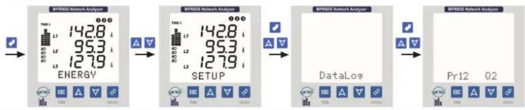
flowchart
graph LR
    A["Energy Display"] --> B["Setup Display"]
    B --> C["Data Loss"]
    C --> D["Pr12 Q2 Output"]
Figure 20: Setting the "Pr12" Parameter
Per (Period Menu)
Period is the time interval between 2 consecutive records and can be set between 5 - 32.000 seconds.
If period is set to "off", then no parameters will be recorded.

flowchart
graph LR
    A["Energy Input"] --> B["MFR025 Network Analyzer"]
    B --> C["SETUP"]
    C --> D["DataLos"]
    D --> E["Return to Data Loss"]
Figure 21: Setting the period time

Warning :
You may quit all settings any time by ESC key.
You must record any change in the settings by → menu key.

Event
When "event" is on, the associated parameter array is recorded in case any of the output relays are switched on / off, regardless of period. So, the parameter values can be examined at the time of relay switching on.

flowchart
graph LR
    A["Energy Display"] --> B["Setup Display"]
    B --> C["DataLoss Event"]
Figure 22: Setting the event
4.6 1. Relay 1 and 2. Relay 2
Device has 2 relays (NO Normally open) for alarm outputs.
Any 3 parameters can be associated with any of the two relays at the same time. For each parameter, under, over, hysterisis and time delay values can be programmed. If the measured value of the set parameter exceeds the programmed values during the delay time, output relay switches on.
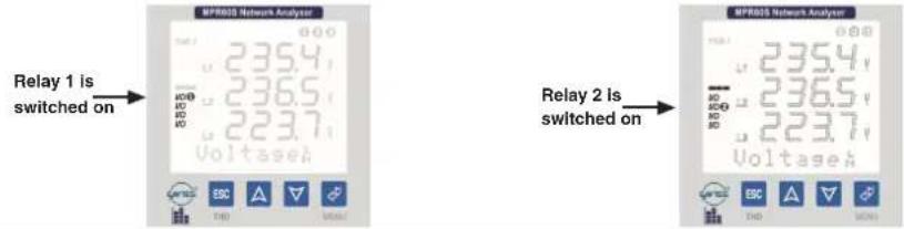
Figure 23: Active relays are displayed on LCD.
The list of the parameters which can be associated with relays are marked with * on parameter table on page 41.
Relay 1 / (Relay 2) has 16 sub-menus.
Cfg: Configuration
Pr : Parameter
Hi : High (over)
Lo : Low (under)
Hs : Hysterisis
Dly : Time Delay
Menu of 1st Parameter
"Pr1:...", "Hi1:...", "Lo1:...", "Hs1:...", "Dly1:..."
Menu of 2nd Parameter
"Pr2:...", "Hi2:...", "Lo2:...", "Hs2:...", "Dly2:..."
Menu of 3rd Parameter
"Pr3:...", "Hi3:...", "Lo3:...", "Hs3:...", "Dly3:..."
Cfg (Configuration)
By this parameter, relays can be configured as "Alarm Output" (Cfg: Alarm) or as "Remote Control" (Cfg: DOut).

flowchart
graph LR
    A["Energy Display"] --> B["Setup"]
    B --> C["Relay1"]
    B --> D["Relay2"]
    C --> E["Cfs:Alrm"]
    D --> F["Cfs:DOut"]
Figure 24: Relay control type setting

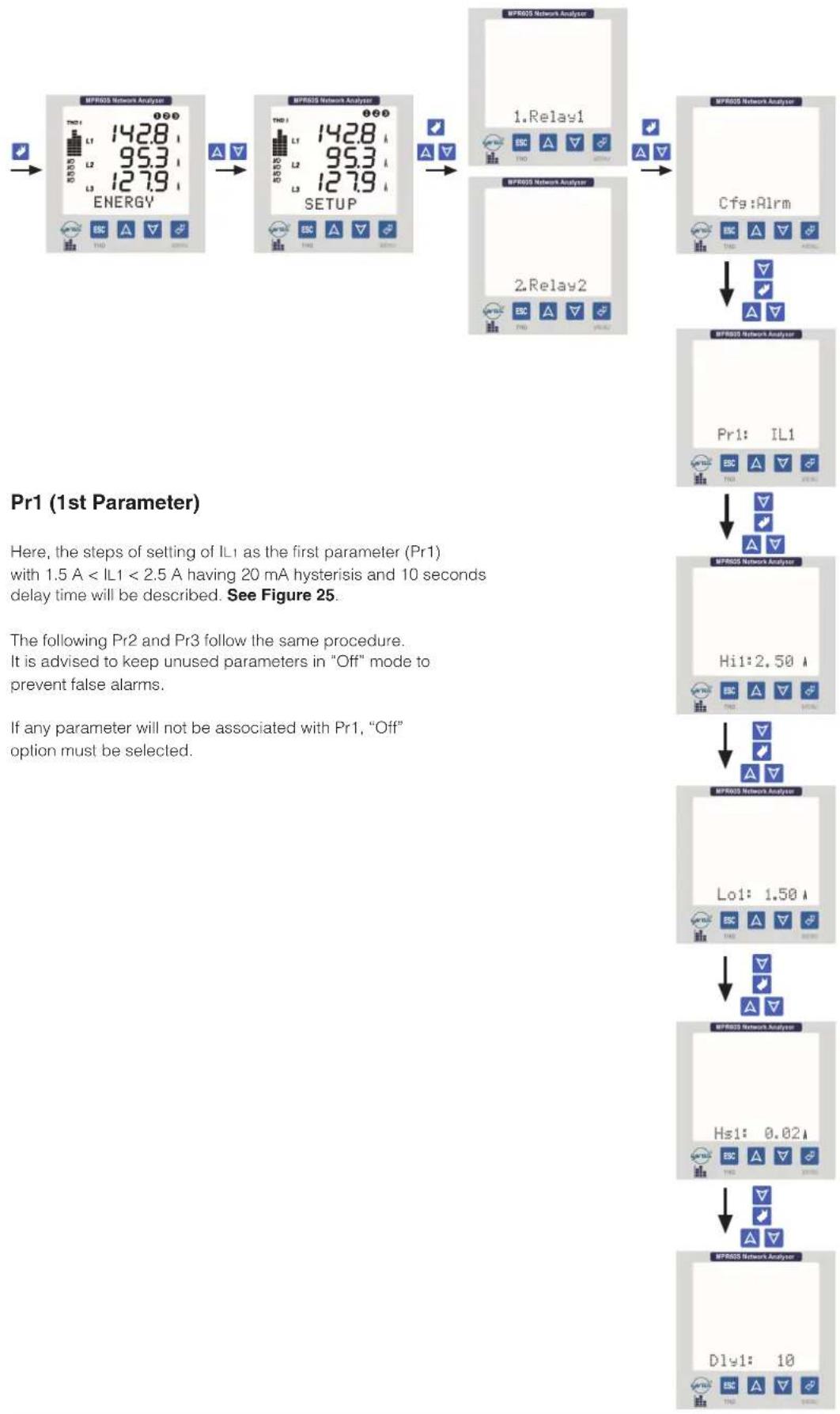
flowchart
graph TD
    A["Pr1 (1st Parameter)"] --> B["Step 1: Setting of IL1 as the first parameter (Pr1) with 1.5 A < IL1 < 2.5 A having 20 mA hysteresis and 10 seconds delay time will be described. See Figure 25."]
    B --> C["Step 2: Setting of IL1 as the first parameter (Pr1) with 1.5 A < IL1 < 2.5 A having 20 mA hysteresis and 10 seconds delay time will be described. See Figure 25."]
    C --> D["Step 3: Setting of IL1 as the first parameter (Pr1) with 1.5 A < IL1 < 2.5 A having 20 mA hysteresis and 10 seconds delay time will be described. See Figure 25."]
    D --> E["Step 4: Setting of IL1 as the first parameter (Pr1) with 1.5 A < IL1 < 2.5 A having 20 mA hysteresis and 10 seconds delay time will be described. See Figure 25."]
    E --> F["Step 5: Setting of IL1 as the first parameter (Pr1) with 1.5 A < IL1 < 2.5 A having 20 mA hysteresis and 10 seconds delay time will be described. See Figure 25."]
    F --> G["Step 6: Setting of IL1 as the first parameter (Pr1) with 1.5 A < IL1 < 2.5 A having 20 mA hysteresis and 10 seconds delay time will be described. See Figure 25."]
    G --> H["Step 7: Setting of IL1 as the first parameter (Pr1) with 1.5 A < IL1 < 2.5 A having 20 mA hysteresis and 10 seconds delay time will be described. See Figure 25."]
    H --> I["Step 8: Setting of IL1 as the first parameter (Pr1) with 1.5 A < IL1 < 2.5 A having 20 mA hysteresis and 10 seconds delay time will be described. See Figure 25."]
Figure 25: Setting of IL1 as the first parameter with 1.5 A < IL1 < 2.5 A having 20 mA hysteresis and 10 seconds delay time.

Warning :
You may quit all settings any time by ESC key.
You must record any change in the settings by

menu key.
Hi1 (High / over value for the 1st parameter)
When the measured value is over the Hi1 value, Relay 1 (or Relay 2) is switched on complying with Hs1 (Hysterisis 1) and Dly1 (Delay 1) values.

flowchart
graph LR
    A["(Hysterisis 1) and Dly1 (Delay 1) values."] --> B["Energy Display"]
    B --> C["Setup"]
    C --> D["Relay1 Output"]
    C --> E["Relay2 Output"]
    D --> F["Hi: ----"]
    E --> F
Figure 26: Setting the high (over) value for the 1st parameter
Lo1 (Low / under value for the 1st parameter)
When the measured value is under the Lo1 value, Relay 1 (or Relay 2) is switched on complying with Hs1 (Hysterisis 1) and Dly1 (Delay 1) values.

flowchart
graph LR
    A["(Hysterisis 1) and Dly1 (Delay 1) values."] --> B["Energy Display"]
    B --> C["Setup"]
    C --> D["Relay1 Output"]
    C --> E["Relay2 Output"]
    D --> F["Loi: ----"]
Figure 27: Setting the low (under) value for the 1st parameter
Hs1 (Hysteresis value for the 1st parameter)
This function is added to prevent system from unexpected oscillations during switch off.
When the switch off values of the associated parameters are over (or under) of Lo1 (or Hi1) values as the hysterisis value respectively, the Relay1 switches off.

flowchart
graph LR
    A["MPR005 Network Analyzer"] --> B["Energy Display"]
    B --> C["MPR005 Network Analyzer"]
    C --> D["SETUP"]
    D --> E["MPR005 Network Analyzer"]
    E --> F["Hs1: ----"]
Figure 28: Setting the hysteresis value for the 1st parameter

Warning :
You may quit all settings any time by ESC key.
You must record any change in the settings by menu key.

Dly1 (Delay time for the 1st parameter)
When the triggering signal is sent to the relay1, the relay1 will wait during the delay time before switching on. If the alarm signal is over during the delay time, the relay1 will not switch on.

flowchart
graph LR
    A["NFR80S Network Analyzer"] --> B["NFR80S Network Analyzer"]
    B --> C["1. Relay1"]
    B --> D["2. Relay2"]
    C --> E["Dly1: ---"]
    D --> E
Figure 29: Setting the delay time for the 1st parameter.

Warning
Where more than one parameter is associated with the output relay, and when the output relay is triggered by more than one measure, switch-off will be realized by the last remaining measure.
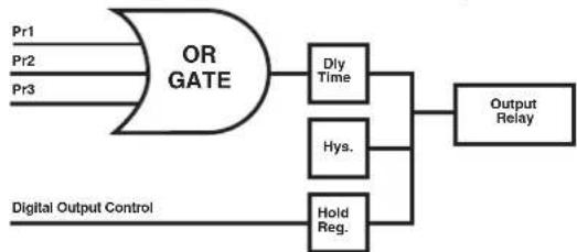
flowchart
graph LR
    A["OR GATE"] --> B["Dly Time"]
    A --> C["Hys."]
    A --> D["Hold Reg."]
    E["Digital Output Control"] --> D
    B --> F["Output Relay"]
    C --> F
    D --> F
4.7 Pulse Outputs (3. Pulse A / 4. Pulse R) (MPR60S/MPR60S-21/41)
Device has 2 Pulse Outputs. It is possible to see, which one of these outputs generate pulse, from the LCD at any time.

Each time the consumed energy increases by an increment of "Prm", a pulse, as long as the "Dur" value entered (msec), is produced in the Pulse Outputs.

line
| Time (msec) | Energy | |-------------|--------| | 0 | 0 | | 3 | 1 | | 6 | 2 | | 9 | 3 | | 12 | 4 | | 15 | 5 | | 18 | 6 | | 21 | 7 | | 24 | 8 | | 27 | 9 | | 30 | 10 |Figure 30: Energy - Pulse output graphic


Warning :
You may quit all settings any time by ESC key.
You must record any change in the settings by

menu key.
3. Pulse A (Import Active Energy Pulse Output) /
4. Pulse R (Inductive Reactive Energy Pulse Output)
A pulse is generated in 3. Pulse A relevant with the import active energy value or in 4. Pulse R relevant with the inductive reactive energy value. For example, a pulse for every increase of 10 kWh for 3. Pulse A or for every increase of 10 kVArh for 4. Pulse R.
- Pulse A (4. Pulse R) has 2 sub-menus. "Prm: ...", "Dur: ..."
Prm (Import Active / Inductive Reactive Energy Value to Set for 1 Pulse)
A pulse is generated from 3. Pulse A output for each increase of the Prm value by a desired amount (1 kWh...50.0 MWh / 1 kVArh...50.0 MVArh)

flowchart
graph LR
    A["Energy Input"] --> B["Energy Display"]
    B --> C["SETUP"]
    C --> D["Pulse A"]
    D --> E["Pulse R"]
    E --> F["Output: Prm: 1 kW"]
Figure 31: Setting the parameter value
Dur (Pulse Width in Miliseconds)
The pulse width is adjusted between 100 - 2500 msec.

flowchart
graph LR
    A["MFR02S Network Analyzer"] --> B["Energy"]
    B --> C["L1: 142.8, L2: 95.3, L3: 127.9"]
    C --> D["L1: 142.8, L2: 95.3, L3: 127.9"]
    D --> E["SETUP"]
    E --> F["L1: 142.8, L2: 95.3, L3: 127.9"]
    F --> G["3. Pulse A"]
    F --> H["4. Pulse R"]
    G --> I["Dur: 250"]
    H --> I
Figure 32: Setting the pulse width.

See page 33 for energy measurement.
Note : Even though the sub-menus under the 3. Pulse A and 4. Pulse R have the same names, these menus are independent of each other.
For Example:
It is possible to enter a specific parameter to the sub-menu "Prm" of 3. Pulse A and a different parameter to the sub-menu "Prm" of 4. Pulse R.

Warning :
You may quit all settings any time by ESC key.
You must record any change in the settings by

menu key.
4.8 Digital Inputs (3. Input-1 / 4. Input-2) (Only for MPR60S-10/20/40)
Device has 2 digital inputs. User can monitor the applied voltage to the input on the LCD display.

flowchart
graph LR
    A["MPR02S Network Analyzer"] --> B["Energy"]
    B --> C["MPR02S Network Analyzer"]
    C --> D["SETUP"]
    D --> E["MPR02S Network Analyzer"]
    E --> F["Fn:Real"]
    E --> G["MPR02S Network Analyzer"]
    G --> H["Fn:Latch"]
Figure 30: Setting the function value
- In order to configure Input-1 function, in 0165 H register:
- "0" has to be entered for Real Time and
- "1" has to be entered for Latch.
- In order to configure Input-2 function, in 0166 H register:
- "0" has to be entered for Real Time and
- "1" has to be entered for Latch.
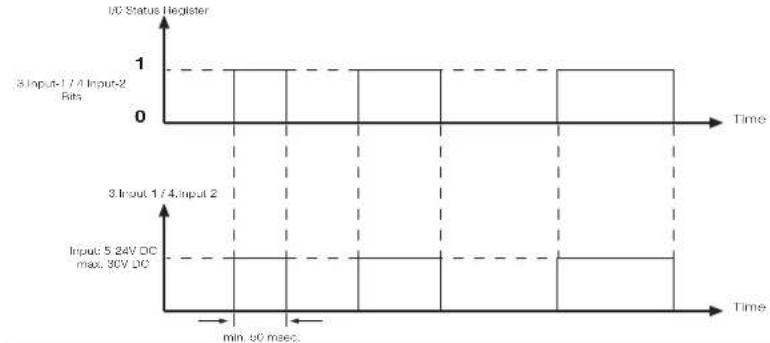
line
| Time | 3 Input-1 / 4 Input-2 Bits | Input: 5 24V DC max. 30V DC | |------|-----------------------------|------------------------------| | min | 0 | 0 | | 50 | 1 | 1 | | 1/4 | 1 | 1 | | 2/4 | 1 | 1 | | 3/4 | 1 | 1 | | max | 1 | 1 | | 30V | 1 | 1 | | max | 1 | 1 | | 50V | 1 | 1 | | max | 1 | 1 | | min | 0 | 0 |Figure 31: Real Time function operation
- In order to reset input registers, which are set in latch function, "0" bit has to be written in I/O status register.
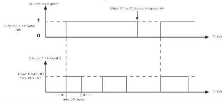
line
| Input Event | I/O Status Register | Output Signal | |-------------|---------------------|---------------| | 3 Input-1 / 4 Input-2 Bits | 1 | 5 24V DC | | 3 Input-1 / 4 Input-2 Bits | 0 | 30V DC | | 3 Input-1 / 4 Input-2 Bits | 1 | min. 60 msec | | 3 Input-1 / 4 Input-2 Bits | 0 | Time |Figure 32: Latch function type operation.
Addres: 004C H

Input 1 and Input 2 register bits show inputs status.

Warning :
You may quit all settings any time by ESC key.
You must record any change in the settings by

menu key.
4.9 Display
In this menu, LCD display settings are configured. It has 3 sub-menus. "Loop: ...", "Cont: ...", "BL: ..."
Loop (Loop duration)
In this menu, the duration of displaying instantaneous value is adjusted automatically. The Loop duration can be adjusted as "No" or between 1...600 in terms of seconds.
For example; when the loop duration is set as 10sec. in the Instantaneous Values menu, if any button is not pressed during 10 sec. the Instantaneous values are displayed in sequence for 10 seconds periods.
By using this function all instantaneous values can be observed sequentially without pressing any buttons.
This function can be cancelled by selecting "No" option in the Loop Menu.

flowchart
graph LR
    A["Energy Input"] --> B["MPR05 Network Analyzer"]
    B --> C["Setup"]
    C --> D["Display"]
    D --> E["Loop: No"]
Figure 33: Setting the loop duration
Cont (Contrast - LCD Display Clarity Settings)
The value can be set between 1....6.

flowchart
graph LR
    A["Energy Input"] --> B["MPR025 Network Analyzer"]
    B --> C["SETUP"]
    C --> D["Display"]
    D --> E["Control: 6"]
Figure 34: Setting the contrast clarity
BL (Backlight)
Measured values can easily be read on the LCD screen even in dark environments with feature of the backlight function.
On : Backlight is On continuously.
Off : Backlight is Off continuously.
Auto : Backlight is switched on automatically when a button is pressed. It is switched off automatically at the end of 30 seconds if any button is not pressed again.

flowchart
graph LR
    A["Energy Input"] --> B["Energy Display"]
    B --> C["Display"]
    C --> D["Auto Output"]
Figure 35: Setting the contrast clarity
4.10 INSTANTANEOUS VALUES
This menu is the last menu that is reached by pressing ESC button while in any menu.
Also it is the main menu of device. If you wait a while without pressing any buttons in any menu, the Instantaneous value menu automatically comes back.
When device is energized for the first time, the device is in the Instantaneous values menu and shows the instantaneous values.
The display is seen as below.
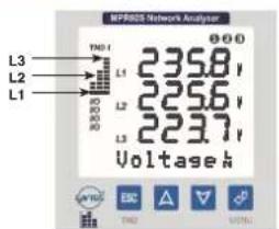
At the bottom of the screen, the active sub-menu is displayed. Each bar on the left indicates the ratio between total harmonic amount of current or voltage for each phase as a percentage value. Each step is 10%. It is possible to switch between "THD V" and "THD I" by ESC button. Also, it is possible to see the numerical values of the THD values by going to the Instantaneous Values Menu.
THD V : Total Harmonic Distortion of Voltage
THD I : Total Harmonic Distortion of Current
Note: When device's phase voltages exceed 330.0 V, phase-phase voltages exceed 530.0 V, phase currents exceed 5.500 A according to upper limits of measurement, "HIGH" is displayed on display.
By scrolling with ▲(UP), ▼(DOWN) buttons while in the Instantaneous Values Menu, the below parameters of the network are displayed.
| Voltage_N^L | - Voltage_L^L | - Currents | - | P. Factor | - Cosφ | - Active (W) |
| Reactive (VAr) | - Apparent (VA) | - ΣPowers | - | Σ P.F. | - THD V % | - THD I % |
| Freq. Hz | - Average_N^L | - Average_L^L | - | ΣCurrent | - In Neutral Current (A) | |
Voltager
VL1, VL2, VL3
Measured phase-neutral voltage value

Voltaget
VL1-2, VL2-3, VL3-1
Measured phase-phase voltage value

Currents
IL1, IL2, IL3
Current measure of each phase

P.Factor
PF L1, PF L2, PF L3
Power factor measure of all phases
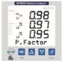
Cosψ
Cosφ L1, Cosφ L2, Cosφ L3

Active
P L1, P L2, P L3
Active power measure of all phases

Reactive
Q L1, Q L2, Q L3
Reactive power measure of all phases
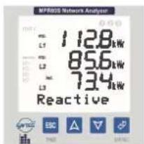
Apparent
S L1, S L2, S L3
Apparent power measure of all phases
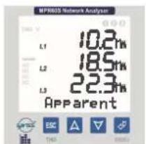
other
BPRGS Network Analysis | Category | Value (%) | |---|---| | L1 | 10.2 | | L2 | 18.5 | | L3 | 22.3 | ApparentΣPowers ΣP, ΣQ, ΣS
Measured total active, total reactive and total apparent power values
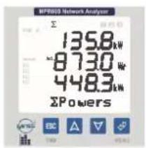
other
MPPBOS Network Analyzer | Current (kW) | Power (kW) | | :--- | :--- | | 135.8 | 1 | | 873.0 | 1 | | 448.3 | 1 | ΣPowersΣP.F.
Total power factor values of all phases

THD ∪%
The total harmonic values for voltages of each phase
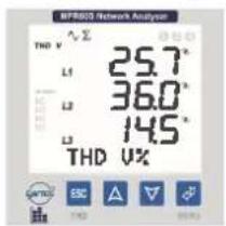
THD 1%
The total harmonic values for currents of each phase

NOTES:
* If there is “-” symbol before the measured active power, it indicates the existence of active export power.
* When ARON connection is chose, "L2 ----" symbol is seen at the Currents. P.Factor, Cosφ. Active. Reactive. Placement THD I% DEMAND DEMAND DEMAND IL menus.
* The total current-voltage harmonic values are displayed in THD V% and THD I% menus as graphic bars on the left. Any time at the instantaneous values menu (except THD V% and THD I%), you can scroll between THD V and THD I with pressing ESC button. Harmonic menu can be used for watching the harmonic values detailed.
Freq. Hz
Frequency of the system.
(The frequency is measured from the L1 phase.)
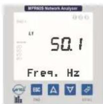
Average
The average value of the measured phase-neutral voltages

Averaget
The average value of the measured phase-phase voltages
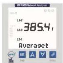
ΣCurrent
The total current value of all phases
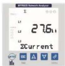

Watching the Values of the Other Parameters
Other parameters are grouped under the; ENERGY, DEMAND, TIME, DATE menus.
4.11 ENERGY
The Energy Values:
In this menu, below energy values are displayed and cleared.
Exp. Export Active Energy Imp. Import Active Energy
- Inductive Reactive Energy Capacitive Reactive Energy values
These energy values can be cleared one by one or all at once.
Imp. (Import Active Energy)

Figure 36: Import Active Energy value
Clearing the Import Active Energy value
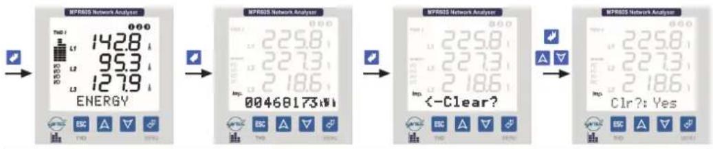
Figure 37: Clearing the Import Active Energy value
Exp. (Export Active Energy value)

Figure 38: Export Active Energy value
Clearing the Export Active Energy value

Figure 39: Clearing the Export Active Energy value
Ind. (Inductive Reactive Energy)

Figure 40: Inductive Reactive Energy value

Warning :
You may quit all settings any time by ESC key.
You must record any change in the settings by

menu key.
Clearing the Inductive Reactive Energy value

Figure 41: Clearing the Inductive Reactive Energy value
Cap. (Capacitive Reactive Energy)
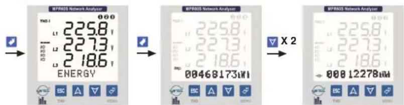
Figure 42: Capacitive Reactive Energy value.
Clearing the Capacitive Reactive Energy value

Figure 43: Clearing the Capacitive Reactive Energy value
Clearing all energy values (Exp, Imp, Ind, Cap)

Figure 44: Clearing all energy values

Warning :
You may quit all settings any time by ESC key.
You must record any change in the settings by menu key.

menu key.
4.13 DEMAND
Observing Demand, min. and max. Values
Demand : It shows the averages which arise on power and current during demand time.
min. value : It shows the min. value different from zero that measured on voltages.
max. value : It shows the max. value that measured on voltages.
*max.VL-N (max. voltage values between Phase-Neutral)
*min.VL-N (min. voltage values between Phase-Neutral)
*max. Demand IL (Max. demand values of phase currents)
*min. Demand IL (Min. demand values of phase currents)
*Demand IL (Demand values of phase currents)
*max. Demand ΣI and min. Demand ΣI (Total max. and min. demand values of phase current)
*Demand Σ IL (Demand value of total phase current)
*Demand ΣP, Demand ΣQ and Demand ΣS (Demand values of total power values)
max. Demand P , max. Demand Q and max. Demand S (Max. demand values of total powers)
min. Demand P , min. Demand Q and min. Demand S (Min. demand values of total powers)
Minimum, maximum and demand values can be cleared one by one or all at once.
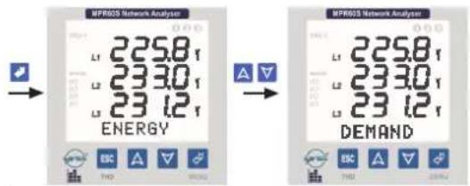
Figure 45: Demand values
max. VLN (Max. values of the phase-neutral voltages)

Figure 46: Max. VLN
Clearing the max. VLN (Max. values of the phase-neutral voltages)

Figure 47: Clearing the max. VLN
Observing the min. VLN (Min. values of the phase-neutral voltages)

Figure 48: Min. VLN value

Warning :
You may quit all settings any time by
You must record any change in the settings by

menu key.
Clearing the min. VLN (Min. values of the phase-neutral voltages)

Figure 49: Clearing the min. V LN value
max. Demand IL (Max values of phase currents)

Figure 50: Max. Demand IL value
Clearing the max. Demand IL (Max values of phase currents)

Figure 51: Clearing the max. Demand II. value
min. Demand IL (Min values of phase currents)

Figure 52: Min. Demand IL value
Clearing the min. Demand IL (Min values of phase currents)

Figure 53: Clearing the min. Demand IL value

Warning :
You may quit all settings any time by ESC key.
You must record any change in the settings by menu key.

menu key.
Demand IL (Demand values of the currents)
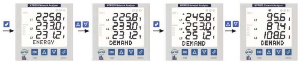
Figure 54: Demand IL
Clearing the Demand IL (Demand values of the currents)

Figure 55: Clearing the demand IL
Demand I , Min. / Max. Demand I (Demand, Min and max demand values of total phase currents)

Figure 56: Min. Demand / Demand Max. Σ |
Clearing Demand I , Min. / Max. Demand I (Demand, Min and max demand values of total phase currents)
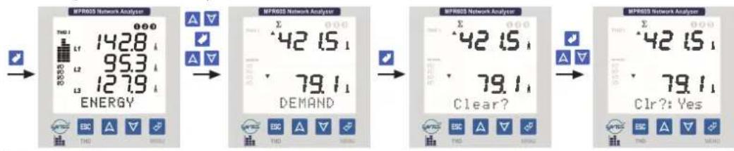
Figure 57: Clearing the Min. Demand / Max. Demand Σ I
Demand Powers (Demand values of total powers)
Active (P), Reactive (Q) and Apparent (S) Powers

Figure 58: Demand Σ Powers
Clearing the Demand Powers (Demand values of total powers)
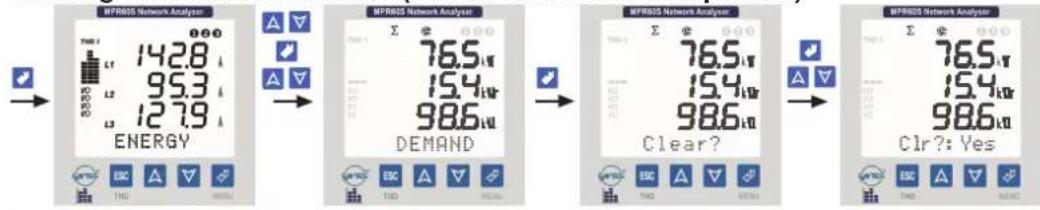
Figure 59: Clearing the Demand Σ Powers
Clearing All Demand values and Min. / Max. Values at Once

flowchart
graph LR
    A["Energy Conversion"] --> B["Energy Conversion"]
    B --> C{Clear?}
    C --> D["Energy Conversion"]
    D --> E{All!}
    E --> F["Energy Conversion"]
Figure 60: Clearing all demand values and min. / max. values at once
Max. Demand Powers (Max. demand values of total powers)

Figure 61: Max. demand value of Σ Powers
Max. Demand Powers (Clearing max. demand values of total powers)

Figure 62: Clearing max. demand values of Σ Powers
Min. Demand Powers (Min. demand values of total powers)

Figure 63: Max. demand value of Σ Powers
Min. Demand Powers (Clearing min. demand values of total powers)

Figure 64: Clearing max. demand values of Σ Powers
Clearing All Demand values and Min. / Max. Values at Once

flowchart
graph LR
    A["Energy Consumption"] --> B["Data Output"]
    B --> C{Clear?}
    C --> D["Output: MPRGS Network Analysis"]
    D --> E{Clr All!}
    E --> F{Clr?: Yes}
Figure 65: Clearing all demand values and min. / max. values at once
4.13 TIME AND DATE
Time and Date Menus
Time and Date, which are configured from the SETUP menu, are kept in the memory.
Even if the power is switched off, the informations of time and date are saved into the memory.
TIME (Menu for observing the time)

Figure 66: Time
Date (Menu for observing the date)

Figure 67: Date
4.14 INFO
INFO
The information about the memory of the device and the manufacturer are seen in this menu.
Information menu has three sub-menus.
Log.Rec..... Eng. Rec.....Producer-Production Information.....
Log. Rec.:
This menu gives us information about the quantity of record lines of the parameters from Pr1 to Pr28 at the top line and indicates the occupied memory.

Figure 68: Info
Above, 14760 record lines are memorised and 98.4% of the memory is used.
See page 23 for Datalog Menu
Clearing all recorded parameters from Pr1 to Pr28 in Log. Rec. permanent memory

Figure 69: Clearing all recorded parameters
Eng. Rec. (Energy recording)
Device records all energy values ( Export Active, Import Active, Inductive Reactive, Capacitive Reactive) in the permanent memory for energy values in every 15 minutes.
1.000 record lines are allocated for energy values. When this area is filled, all energy recordings are cleared to enable further records.

Note: Allocated areas for parameter and energy values are independent from each others. The permanent memory is not affected from power cuts.
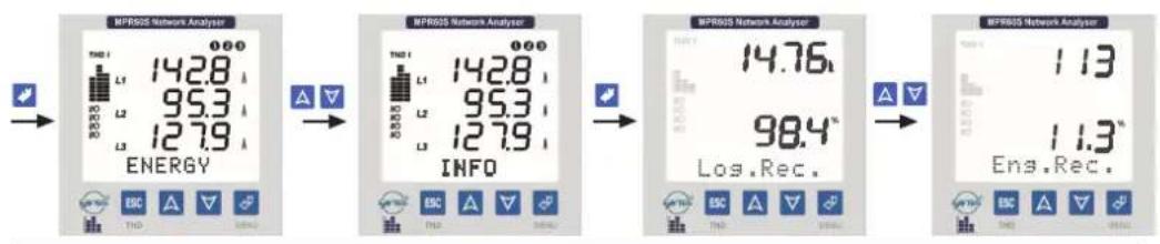
Figure 70: Energy records
Above, 113 record lines are memorised and 11.3% of the memory is used.
Clearing all recorded parameters from Pr1 to Pr28 in the Eng. Rec. permanent memory
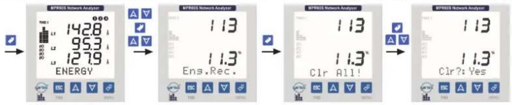
Figure 71: Clearing all recorded parameters in the Eng. Rec. permanent memory

Note : If data records, which are saved in to the permanent memory for every 15 minutes in Eng.Rec. Menu, are cleared, energy values are not affected from this event.
4.15 Manufacturer - Product Information
Information about manufacturer, the version number of the device, company contact information and serial number (8 digit) are on this menu.

Figure 72: Manufacturer - Product Information
4.16 PASSWORD
User password is set and activated in this menu.
In order to prevent the device's SETUP, DEMAND and ENERGY menus from unauthorized access, it is necessary to set up a 3 digit user password and then activate it.
Set Psw (Menu for setting up a user password)

flowchart
graph LR
    A["Start"] --> B["UPR60S Network Analyzer"]
    B --> C["UPR60S Network Analyzer"]
    C --> D["UPR60S Network Analyzer"]
    D --> E["Set Psw"]
    E --> F["UPR60S Network Analyzer"]
    F --> G["New 000"]
Figure 73: Setting the password
Chg Psw (Menu for changing the user password)
The new password is saved to the SETUP, DEMAND and ENERGY menus.
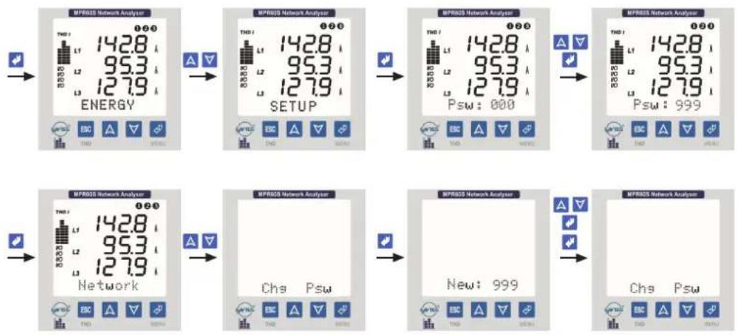
flowchart
graph TD
    A["Energy"] --> B["Setup"]
    B --> C["Psw: 000"]
    C --> D["New: 999"]
Figure 74: Changing the password
Main Password: 236
4.17 PARAMETER TABLE
The parameters, that can be set, are marked with an * symbol in the parameter table.
| *VL1, L2, L3 | (Phase Voltage) |
| *VL12, L23, L31 | (Phase-Phase Voltage) |
| *VN (Average) | (Total Phase Voltage Average) |
| *VL (Average) | (Total Phase-Phase Voltages Average) |
| *Freq.Hz | (Frequency) |
| *IL1, L2, L3 | (Phase Currents) |
| *ΣI | (Total Phase Currents) |
| *PL1, L2, L3(W) | (Acive Power) |
| *QL1, L2, L3(VAr) | (Reactive Power) |
| *SL1, L2, L3(VA) | (Apparent Power) |
| *ΣP. (W) | (Total Active Power) |
| *ΣQ. (VAr) | (Total Reactive Power) |
| *ΣS. (VA) | (Total Apparent Power) |
| *COSφL1, L2, L3 | (Displacement Power Factor) |
| *PFL1, L2, L3 | (Power Factor) |
| ΣP. F | (Total Power Factor) |
| Exp.(KWh) | (Export Active Energy) |
| Imp.(KWh) | (Import Active Energy) |
| Ind. (KVArh) | (Inductive Reactive Energy) |
| Cap.(KVArh) | (Capacitive Reactive Energy) |
| *H-VL1, L2, L3 | (Harmonic Values for Voltages) |
| *H-IL1, L2, L3 | (Harmonic Values for Currents) |
| *Max.VLN | (Maksimum Phase Voltage) |
| *Min. VIN | (Minimum Phase Voltage) |
| *Max. Demand IL | (Max. Demand of Phase Currents) |
| *Min. Demand IL | (Min. Demand of Phase Currents) |
| *Max. Demand ΣI | (Max. Demand of Total Phase Currents) |
| *Min. Demand ΣI | (Min. Demand of TotalPhase Currents) |
| *Demand IL | (Demand of Phase Currents) |
| *Demand ΣIL | (Demand of Total Phase Currents) |
| *Demand ΣW | (Demand of Total Active Powers) |
| *Demand ΣVAr | (Demand of Total Reactive Powers) |
| *Demand ΣVA | (Demand of Total Apparent Powers) |
| Hr. | (Hour) |
| Min. | (Minute) |
| Sec. | (Second) |
| Day | (Day) |
| Mo. | (Month) |
| Year | (Year) |
| CTR | (Current Transformer Ratio) |
| VTR | (Voltage Transforemr Ratio) |
| IOS | (Relay Position) |
| *In | (Neutral Current) |
| Max. Demand ΣW | (Max. Demand of Total Active Powers) |
| Max. Demand ΣVAr | (Max. Demand of Total Reactive Powers) |
| Max. Demand ΣVA | (Max. Demand of Total Apparent Powers) |
| Min. Demand ΣW | (Min. Demand of Total Active Powers) |
| Min. Demand ΣVAr | (Min. Demand of Total Reactive Powers) |
| Min. Demand ΣVA | (Min. Demand of Total Apparent Powers) |
4.18 FORMULAS
| RMS Values for Voltages | V_rms = 1N_i=0^Nv^2 | RMS Values for Currents | I_rms = 1N_i=0^Nt_i^2 |
| Total Active Power | P = 1N_i=0^Np_i | Total Reactive Power | Q = 1N_i=0^Nq_i |
| Apparent Power | S = P^-2 + Q^2 | Total Power Factor | P.F = P S |
| Total Harmonic Distortion for Voltages | V_THD% = _i=2^31V_i^2V_i × 100 | ||
| Total Harmonic Distortion for Currents | I_THD% = _i=2^31I_i^2I_i × 100 | ||
4.19 Current Analog Output (0/4-20mA) (Only for MPR60S-40/41)

flowchart
graph LR
    A["Energy Display"] --> B["Setup"]
    B --> C["Anls.Out"]
    C --> D["Output: Type0-20"]
In device, this feature gives the possibility that observing the measured values by other devices with converting these values in to 0-20 mA or 4-20 mA current data. The below parameters can be set as analog output in device.
The below parameters can be set as analog output :
VL1, L2, L3 (V) (Phase Voltage)
VL12, L23, L31 (V) (Phase-Phase Voltage)
V. (Average) (Average of the total phase voltages)
V. (Average) (Average of the total phase-phase voltages)
Frequency (Hz) (Frequency)
L1, L2, L3 (A) (Phase Currents)
THD %VL1, L2, L3 (Total Harmonic Values for Voltages)
THD %| L1, L2, L3 (Total Harmonic Values for Currents)
PL1, L2, L3 (W) (Active Power)
QL1, L2, L3 (VAr) (Reactive Power)
SL1, L2, L3 (VA) (Apparent Power)
Σl. (A) (Total Phase Currents)
ΣP. (W) (Total Active Power)
ΣQ. (VAr) (Total Reactive Power)
ΣS. (VA) (Total Apparent Power)
For example
Below settings should be fulfilled as like :
Type : 0-20 mA
After above settings are completed;
Analog current output's value will be 0 mA when VL1 value is 0 V,
Analog current output's value will be 20 mA when VL1 value is 300 V.
When VL1 is 220 V analog voltage output value will be;
$$ \mathrm{Iout} = \frac {(2 0 - 0) \times (2 2 0 - 0)}{(3 0 0 - 0)} = 1 4, 6 7 \mathrm{mA} $$
For example
Below settings should be fulfilled as like :
Type : 0-20 mA
After above settings are completed;
Analog current output's value will be 0 mA when PL1 value is -650 W,
Analog current output's value will be 20 mA when PL1 value is 350 W
When PL1 is -300 W analog voltage output value will be;
$$ \text { lout } = \frac {(2 0 - 0) \times [ - 3 0 0 - (- 6 5 0) ]}{[ 3 5 0 - (- 6 5 0) ]} = 7 \mathrm{mA} $$
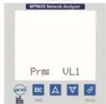


4.20 Voltage Analog Output (0/2-10V) (Only for MPR60S-20/21)
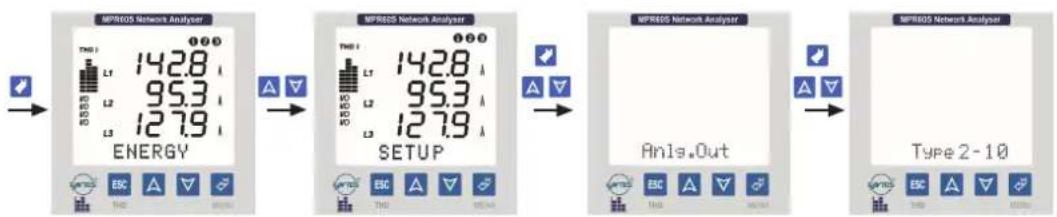
flowchart
graph LR
    A["Energy Display"] --> B["Setup"]
    B --> C["Analysis Setup"]
    C --> D["Type 2-10 Analyzer"]
In device, this feature gives the possibility that observing the measured values by other devices with converting these values in to 0-10 V or 2-10 V voltage data. The below parameters can be set as analog output in device.
The below parameters can be set as analog output :
V_L1, L2, L3 (V) (Phase Voltage)
VL12, L23, L31 (V) (Phase-Phase Voltage)
V. 1N (Average) (Average of the total phase voltages)
V. E (Average) (Average of the total phase-phase voltages)
Frequency (Hz) (Frequency)
L1, L2, L3 (A) (Phase Currents)
THD %VL1, L2, L3 (Total Harmonic Values for Voltages)
THD %I L1, L2, L3 (Total Harmonic Values for Currents)
PL1, L2, L3 (W) (Active Power)
QL1, L2, L3 (VAr) (Reactive Power)
SL1, L2, L3 (VA) (Apparent Power)
Σl. (A) (Total Phase Currents)
ΣP. (W) (Total Active Power)
ΣQ. (VAr) (Total Reactive Power)
ΣS. (VA) (Total Apparent Power)
For example
Below settings should be fulfilled as like :
Type : 2-10 V
After above settings are completed;
Analog voltage output's value will be 2 V when L1 value is 100mA,
Analog voltage output's value will be 10 V when IL1 value is 5 A.
When IL1 is 3.5 A analog voltage output value will be;
$$ \text { I o u t } = \frac {(1 0 - 2) \times (3 . 5 - 0 . 1)}{(5 - 0 . 1)} + 2 = 7. 5 5 1 \mathrm{V} $$
For example
Below settings should be fulfilled as like :
Type : 0-10 V
Prm (Parameter) : SQ
Lo(Low value) : -250 VAr
Hi (High value) : 750 VAr
After above settings are completed;
Analog voltage output's value will be 0 V when SQ value is -250 VAr,
Analog voltage output's value will be 10 V when SQ value is 750 VAr.
When SQ is 400 VAr analog voltage output value will be;
$$ \text { I o u t } = \frac {(1 0 - 0) \times [ 4 0 0 - (- 2 5 0) ]}{[ 7 5 0 - (- 2 5 0) ]} = 6. 5 \mathrm{V} $$

4.21 FACTORY SETTINGS
Network
| CT (Current transformer) : 10 | |
| VT ( Voltage transformer) | : 1.0 |
| Net (System Connection) : 3P4W | |
| Eng (Energy) | : Tot. |
| E.Unit (Energy Unit) | : k |
Display
| Loop (Loop duration) | : No |
| Cont (Contrast) | : 6 |
| BL. (Backlight) | : Auto |
RS-485
| Addr (Address) | : 1 |
| Bd (Baud rate value) | : 9600 bps |
| Prt (Parity) | : None |
Datalog
| Per (Period) | : 900 sec. |
| Event | : No |
| Pr1(Parameter 1) | : VL1 |
| Pr2(Parameter 2) | : VL2 |
| Pr3(Parameter 3) | : VL3 |
| Pr4(Parameter 4) | : IL1 |
| Pr5(Parameter 5) | : IL2 |
| Pr6(Parameter 6) | : IL3 |
| Pr7(Parameter 7) | : ΣI |
| Pr8(Parameter 8) | : P1 |
| Pr9(Parameter 9) | : P2 |
| Pr10(Parameter 10) | : P3 |
| Pr11(Parameter 11) | : Q1 |
| Pr12(Parameter 12) | : Q2 |
| Pr13(Parameter 13) | : Q3 |
| Pr14(Parameter 14) | : S1 |
| Pr15(Parameter 15) | : S2 |
| Pr16(Parameter 16) | : S3 |
| Pr17(Parameter 17) | : PF1 |
| Pr18(Parameter 18) | : PF2 |
| Pr19(Parameter 19) | : PF3 |
| Pr20(Parameter 20) | : Cos1 |
| Pr21(Parameter 21) | : Cos2 |
| Pr22(Parameter 22) | : Cos3 |
| Pr23(Parameter 23) | : V12 |
| Pr24(Parameter 24) | : V23 |
| Pr25(Parameter 25) | : V31 |
| Pr26(Parameter 26) | : VN |
| Pr27(Parameter 27) | : VL |
| Pr28 (Parameter 28) | : Freq. |
1.Relay1
| Cfg | : Digital Output |
| Pr1,Pr2,Pr3 (Parameters) | : Off |
| Hi1,Hi2,Hi3 (High) | : - - - - |
| Lo1,Lo2,Lo3 (Low) | : - - - - |
| Hs1,Hs2,Hs3 (Hysterisis) | : - - - - |
| Dly1,Dly2,Dly3 (Delay) | : - - - - |
2.Relay 2
| Cfg | : Digital Output |
| Pr1,Pr2,Pr3 (Parameters) : Off | |
| Hi1,Hi2,Hi3 (High) : - - - - | |
| Lo1,Lo2,Lo3 (Low) : - - - - | |
| Hs1,Hs2,Hs3 (Hysterisis) : - - - - | |
| Dly1,Dly2,Dly3 (Delay) : - - - - | |
- Pulse A (only for MPR60S/MPR60S-21/41)
| Prm(Energy value to set for 1 pulse) : 1 kWh |
| Dur ( Pulse width) : 250 msec. |
- Pulse R (only for MPR60S/MPR60S-21/41)
| Prm(Energy value to set for 1 pulse) : 1 kVArh Dur (Pulse width) : 250 msec. |
- Input-1 (only for MPR60S-10/20/21)
| Fn : Real Time |
- Input-2 (only for MPR60S-10/20/21)
| Fn : Real Time |
Current Analog Output (only for MPR60S-40/41)
Voltage Analog Output (only for MPR60S-20/21)
| Set Psw (Setting up the password) : None (000) |
4.22 TECHNICAL DATA
Operating Voltage (Un) : Please look behind the device.
Frequency:50760Hz
Power Consumption : < 6 VA
Burden : < 1 VA (Current Burden)
: < 0.5 VA (Voltage Burden)
Measurement Input
Voltage
: 1,0 - 300,0 V AC (L-N)
: 2,0 - 500,0 V AC (L-L)
Current : 0,005 - 5.5 A
Measurement Ranges
Frequency : 45,0 - 65,0 Hz
Power:0-4000 M (W, VAr, VA)
Energy : 0 - 99 999 999 kWh, kVArh or MWh, MVArh
Measurement Category: CAT III
Accuracy
Voltage, Current : 0.5%±2digit
Active Power : 1%±2digit
Reactive, Apparent Power : 2%±2digit
Voltage Transformer Ratio : 1,0...4000,0
Current Transformer Ratio:1...5000
Connection Type: 3P-4W, 3P-3W, ARON
Relay Outputs (2 pcs.)
Demand Time
Communication Interface
Baud Rate
Address
Parity
Data Logging
Parameters
Record Size
Log Duration
(time interval between 2 records)
Energy Record
Event
Memory
Digital Inputs (2 pcs.)
Functions
Input Pulse Width
Operation Voltage
Energy Pulse Outputs (2 pcs.)
Switch Period
Pulse Width
Operation Current
Operation Voltage
Analog Voltage Output
Load Resistance
Response Perriod
Analog Current Output
Load Resistance
Response Perriod
Real Time Clock
Ambient Temperature
Display
Dimensions
Equipment Protection Class
Box Protection Class
Terminal Block Protection Class
Box Material
Installation
Wire Thickness for Voltage Connection
Wire Thickness for Current Connection
Wire Thickness for Pulse or
Digital Input Connection
RS-485 Connection
Weight
Installation Category
Type
Package Dimensions
Package Weight
Pcs për Package
2 NO, 5A, 1250 VA
15 min.
MODBUS RTU (RS-485)
1200 - 38400 bps
1 - 247
None, Even, Odd Parity
Choosen 28 parameters with date and time
15000 record lines
No, 5 - 32.000 seconds
1000 record lines (1 record in every 15 minutes)
Yes, No
1 MB Internal Memory
Real Time / Latch
Min. 50 ms
5...24 V DC, max. 30 V DC
Min. 1 sec.
100-2500 ms
Max. 50 mA
5-24 V DC max. 30 V DC
0-10 V or 2-10 V
≥5 kΩ
1 sec
0-20 mA or 4-20 mA
≤500 Ω
1 sec.
3,6" LCD with Backlight
PR19
Double Insulation-Class II (☐)
IP 40
IP 00
Non-flammable
Flush mounting with rear terminals
2,5 mm²
4.0 mm²
1.5 mm²
Category 5 Cable (Shielded Twisted Pair)
0.75 kg
Class II
PR 19
280x280x265 mm
6 kg
8 pcs
5. Standarts and Explanations
EN 61000-6-2 : Electromagnetic compatibility (EMC). Generic standards. Immunity for industrial environments.
EN 61000-6-4 : Electromagnetic compatibility (EMC). Generic standards. Emission standard for industrial environments.
EN 55016-2-1 : Specification for radio disturbance and immunity measuring apparatus and methods. Methods of measurement of disturbances and immunity. Conducted disturbance measurements.
EN 55016-2-3 : Specification for radio disturbance and immunity measuring apparatus and methods. Methods of measurement of disturbances and immunity. Radiated disturbance measurements.
EN 55011 : Limits and methods of measurement of radio disturbance characteristics of industrial, scientific and medical (ISM) radio-frequency equipment.
EN 61000-3-2 : Electromagnetic compatibility (EMC). Limits for harmonic current emissions (equipment input current < 16A per phase)
EN 61000-3-3 : Electromagnetic compatibility (EMC) - Part 3-3: Limits - Limitation of voltage changes, voltage fluctuations and flicker in public low-voltage supply systems, for equipment with rated current = 16 A per phase and not subject to conditional connection.
EN 61010-1 : Safety requirements for electrical equipment for measurement, control, and laboratory use - Part 1: General requirements.
EN 61000-4-2 : Elektrostatic discharge immunity test.
EN 61000-4-3 : Radiated RF electromagnetic field immunity test.
EN 61000-4-4 : Electrical fast transient/burst immunity test.
EN 61000-4-5 : Surge immunity test.
EN 61000-4-6 : Immunity to RF conducted disturbances.
EN 61000-4-8 : Power frequency magnetic field immunity test.
EN 61000-4-11 : Voltage dips, short interruptions and voltage variations immunity test.
MPR60S MENU MAP
INSTANT VALUES

flowchart
graph TD
    A["Voltage"] --> B["Energy"]
    C["Voltage"] --> B
    D["Current"] --> B
    E["P.Factor"] --> B
    F["Cose"] --> B
    G["Active"] --> B
    H["Reactive"] --> B
    I["Apparent"] --> B
    J["F.Powers"] --> B
    K["SPF"] --> B
    L["THD V%"] --> M["DEMAND"]
    N["THD P%"] --> M
    O["Freq. Hz"] --> P["SETUP"]
    Q["AverageS"] --> P
    R["AverageI"] --> P
    S["Current"] --> P
    T["Energy"] --> U["DET"]
    U --> V["SETUP"]
    V --> W["TIME"]
    W --> X["INFO"]
    X --> Y["Display"]
    Y --> Z["RS-485"]
    Z --> AA["Setup"]
    AA --> AB["Reset2"]
    AB --> AC["Reset2"]
    AC --> AD["Reset2"]
    AD --> AE["Reset2"]
    AE --> AF["Reset2"]
    AF --> AG["Reset2"]
    AG --> AH["Reset2"]
    AH --> AI["Reset2"]
    AI --> AJ["Reset2"]
    AJ --> AK["Reset2"]
    AK --> AL["Reset2"]
    AL --> AM["Reset2"]
    AM --> AN["Reset2"]
    AN --> AO["Reset2"]
    AO --> AP["Reset2"]
    AP --> AQ["Reset2"]
    AQ --> AR["Reset2"]
    AR --> AS["Reset2"]
    AS --> AT["Reset2"]
    AT --> AU["Reset2"]
    AU --> AV["Reset2"]
    AV --> AW["Reset2"]
    AW --> AX["Reset2"]
    AX --> AY["Reset2"]
    AY --> AZ["Reset2"]
    AZ --> BA["Reset2"]
    BA --> BB["Reset2"]
    BB --> BC["Reset2"]
    BC --> BD["Reset2"]
    BD --> BE["Reset2"]
    BE --> BF["Reset2"]
    BF --> BG["Reset2"]
    BG --> BH["Reset2"]
    BH --> BI["Reset2"]
    BI --> BJ["Reset2"]
    BJ --> BK["Reset2"]
    BK --> BL["Reset2"]
    BL --> BM["Reset2"]
    BM --> BN["Reset2"]
    BN --> BO["Reset2"]
    BO --> BP["Reset2"]
    BP --> BQ["Reset2"]
    BQ --> BR["Reset2"]
    BR --> BS["Reset2"]
    BS --> BT["Reset2"]
    BT --> BU["Reset2"]
    BU --> BV["Reset2"]
    BV --> BW["Reset2"]
    BW --> BX["Reset2"]
    BX --> BY["Reset2"]
    BY --> BZ["Reset2"]
    BZ --> CA["Reset2"]
    CA --> CB["Reset2"]
    CB --> CC["Reset2"]
    CC --> CD["Reset2"]
    CD --> CE["Reset2"]
    CE --> CF["Reset2"]
    CF --> CG["Reset2"]
    CG --> CH["Reset2"]
    CH --> CI["Reset2"]
    CI --> CJ["Reset2"]
    CJ --> CK["Reset2"]
    CK --> CR["Reset2"]
    CR --> CS["Reset2"]
    CS --> CT["Reset2"]
    CT --> CU["Reset2"]
    CU --> CV["Reset2"]
    CV --> CW["Reset2"]
    CW --> CX["Reset2"]
    CX --> CY["Reset2"]
    CY --> CZ["Reset2"]
    CZ --> DA["Reset2"]
    DA --> DB["Reset2"]
    DB --> DC["Reset2"]
    DC --> DD["Reset2"]
    DD --> DE["Reset2"]
    DE --> DF["Reset2"]
    DF --> DG["Reset2"]
    DG --> DH["Reset2"]
    DH --> DI["Reset2"]
    DI --> DJ["Reset2"]
    DJ --> DK["Reset2"]
    DK --> DL["Reset2"]
    DL --> DV["Reset2"]
    DV --> DW["Reset2"]
    DW --> DX["Reset2"]
    DX --> DXB["Reset2"]
    DXB --> DXC["Reset2"]
    DXC --> DXD["Reset2"]
    DXD --> DXE["Reset2"]
    DXE --> DXF["Reset2"]
    DXF --> DXG["Reset2"]
    DXG --> DXH["Reset2"]
    DXH --> DXI["Reset2"]
    DXI --> DXJ["Reset2"]
    DXJ --> DXK["Reset2"]
    DXK --> DXL["Reset2"]
    DXL --> DXM["Reset2"]
    DXM --> DXN["Reset2"]
    DXN --> DXO["Reset2"]
INSTANT VALUES

flowchart
graph TD
    A["Voltage k"] --> B["Energy"]
    C["Voltage l"] --> B
    D["Currents"] --> B
    E["P. Factor"] --> B
    F["Cose"] --> B
    G["Active"] --> B
    H["Reactive"] --> B
    I["Apparent"] --> B
    J["L. Powers"] --> B
    K["ΔP.F."] --> L["SETUP"]
    M["THD V%"] --> L
    N["THD 1%"] --> L
    O["Freq. Hz"] --> P["TIME"]
    Q["Everage k"] --> P
    R["Average t"] --> P
    S["Current"] --> P
    T["Energy"] --> U["Demand"]
    U --> V["SETUP"]
    V --> W["Time"]
    W --> X["INFO"]
    X --> Y["Log Rec"]
    X --> Z["Ver."]
    Y --> AA["Log Rec"]
    Y --> AB["Clear"]
    Y --> AC["Clear"]
    U --> AD["Password Defined"]
    U --> AE["Password Defined"]
    U --> AF["Password Defined"]
    U --> AG["Password Defined"]
    U --> AH["Password Defined"]
    U --> AI["Password Defined"]
    U --> AJ["Password Defined"]
    U --> AK["Password Defined"]
    U --> AL["Password Defined"]
    U --> AM["Password Defined"]
    U --> AN["Password Defined"]
    U --> AO["Password Defined"]
    U --> AP["Password Defined"]
    U --> AQ["Password Defined"]
    U --> AR["Password Defined"]
    U --> AS["Password Defined"]
    U --> AT["Password Defined"]
    U --> AU["Password Defined"]
    U --> AV["Password Defined"]
    U --> AW["Password Defined"]
    U --> AX["Password Defined"]
    U --> AY["Password Defined"]
    U --> AZ["Password Defined"]
    U --> BA["Password Defined"]
    U --> BB["Password Defined"]
    U --> BC["Password Defined"]
    U --> BD["Password Defined"]
    U --> BE["Password Defined"]
    U --> BF["Password Defined"]
    U --> BG["Password Defined"]
    U --> BH["Password Defined"]
    U --> BI["Password Defined"]
    U --> BJ["Password Defined"]
    U --> BK["Password Defined"]
    U --> BL["Password Defined"]
    U --> BM["Password Defined"]
    U --> BN["Password Defined"]
    U --> BO["Password Defined"]
    U --> BP["Password Defined"]
    U --> BQ["Password Defined"]
    U --> BR["Password Defined"]
    U --> BS["Password Defined"]
    U --> BT["Password Defined"]
    U --> BU["Password Defined"]
    U --> BV["Password Defined"]
    U --> BW["Password Defined"]
    U --> BX["Password Defined"]
    U --> BY["Password Defined"]
    U --> BZ["Password Defined"]
    U --> CA["Password Defined"]
    U --> CB["Password Defined"]
    U --> CC["Password Defined"]
    U --> CD["Password Defined"]
    U --> CE["Password Defined"]
    U --> CF["Password Defined"]
    U --> CG["Password Defined"]
    U --> CH["Password Defined"]
    U --> CI["Password Defined"]
    U --> CJ["Password Defined"]
    U --> CK["Password Defined"]
    U --> CR["Password Defined"]
    U --> CS["Password Defined"]
    U --> CT["Password Defined"]
    U --> CU["Password Defined"]
    U --> CV["Password Defined"]
    U --> CW["Password Defined"]
    U --> CX["Password Defined"]
    U --> CY["Password Defined"]
    U --> CZ["Password Defined"]

flowchart
graph TD
    A["Voltage 1"] --> B["Currents"]
    B --> C["P. Factor"]
    C --> D["Cos"]
    D --> E["Active"]
    E --> F["Reactive"]
    F --> G["Apparent"]
    G --> H["L. Powers"]
    H --> I["L.P.F."]
    I --> J["THD V%"]
    J --> K["THD 1%"]
    K --> L["Freq. Hz"]
    L --> M["Average s"]
    M --> N["Averaget"]
    N --> O["C. Current"]

    P["ENERGY"] --> Q["EXP."]
    Q --> R["Clear"]
    R --> S["PSW"]
    S --> T["Imp."]
    T --> U["Clear"]
    U --> V["PSW"]
    V --> W["JML"]
    W --> X["Clear"]
    X --> Y["PSW"]
    Y --> Z["Clear"]
    Z --> AA["PSW"]
    AA --> AB["Password Defined"]

    AC["DEMAND"] --> AD["v"]
    AD --> AE["Clear"]
    AE --> AF["PSW"]
    AF --> AG["A"]
    AG --> AH["Clear"]
    AH --> AI["PSW"]
    AI --> AJ["A"]
    AJ --> AK["Clear"]
    AK --> AL["PSW"]
    AL --> AM["RS-485"]

    AN["SETUP"] --> AO["Password Defined"]

    AP["Network"] --> AQ["CT."]
    AQ --> AR["VT."]
    AR --> AS["Nc."]
    AS --> AT["E.C.T."]
    AT --> AU["E.Uric."]

    AV["Display"] --> AW["Loop."]
    AW --> AX["C.unit"]
    AX --> AY["BL"]

    AZ["RS-485"] --> BA["Addr."]
    BA --> BB["Bd."]
    BB --> BC["Pn"]

    BD["Catalog"] --> BE["1. Roten"]
    BE --> BF["Clp."]
    BF --> BG["P1.1"]
    BG --> BH["H1.1"]
    BH --> BI["Lc1.1"]
    BI --> BJ["H1.1"]
    BJ --> BK["Dc1.1"]
    BK --> BL["P2.1"]
    BL --> BM["H2.1"]
    BM --> BN["Lc7.1"]
    BN --> BO["H2.1"]
    BO --> BP["Dy2.1"]
    BP --> BQ["P3.1"]
    BQ --> BR["H3.1"]
    BR --> BS["Lc3.1"]
    BS --> BT["Hck.1"]
    BT --> BU["Dy2.1"]

    BV["2. Relay2"] --> BW["Cip."]
    BW --> BX["P1.1"]
    BX --> BY["H1.1"]
    BY --> BZ["Lc1.1"]
    BZ --> CA["H1.1"]
    CA --> CB["Dc1.1"]
    CB --> CC["P2.1"]
    CC --> CD["H2.1"]
    CD --> CE["Lc7.1"]
    CE --> CF["P3.1"]
    CF --> CG["H3.1"]
    CG --> CH["Lc3.1"]
    CH --> CI["Hck.1"]
    CI --> CJ["Dy2.1"]

    CK["3. Update"] --> CL["Fn."]

    CM["Address"] --> CN["Frc."]
    CN --> CO["Time."]
    CO --> CP["8hmm(y)"]
    CP --> CQ["Date."]
    CQ --> CR["8hmm(y)"]
    CR --> CS["Set Pow."]
    CS --> CT["Password Undefined"]
    CT --> CU["Chg Pow."]
    CU --> CV["Password Defined"]
    CV --> CW["Antic Out."]

    CX["Type"] --> CY["Fpn."]
    CY --> CZ["Lc1.1"]
    CZ --> DA["H2.1"]

    DB["LogRec"] --> DBa["Clear"]
    DBa --> DBb["LogRec"]
    DBb --> DBc["LogRec"]

    DBc --> DBd["Var."]


    style A fill:#f9f,stroke:#333
    style P fill:#ccf,stroke:#333

flowchart
graph TD
    A["Voltage L"] --> B["Voltage I"]
    B --> C["Currents"]
    C --> D["P Factor"]
    D --> E["Cosφ"]
    E --> F["Active"]
    F --> G["Reactive"]
    G --> H["Apparent"]
    H --> I["S Powers"]
    I --> J["ΔP.F."]
    J --> K["THD V%"]
    K --> L["THD I%"]
    L --> M["Freq. Hz"]
    M --> N["Average k"]
    N --> O["Average L"]
    O --> P["Current"]

    Q["ENERGY"] --> R["Exp. Clear PSW"]
    Q --> S["Imp Clear PSW"]
    Q --> T["mm Clear PSW"]
    Q --> U["Clear PSW"]
    Q --> V["Password Defined"]

    W["DEMAND"] --> X["V Clear PSW"]
    W --> Y["V Clear PSW"]
    W --> Z["V Clear PSW"]
    W --> AA["V Clear PSW"]
    W --> AB["V Clear PSW"]
    W --> AC["V Clear PSW"]
    W --> AD["V Clear PSW"]
    W --> AE["V Clear PSW"]
    W --> AF["V Clear PSW"]
    W --> AG["V Clear PSW"]

    AH["SETUP"] --> AI["PSW Password Defined"]
    AH --> AJ["Network CT"]
    AH --> AK["Display Loop"]
    AH --> AL["RSC-182 Addr"]
    AH --> AM["Datakey 1. Rosay"]

    AN["TIME"] --> AO["Log Rec Clear"]
    AN --> AP["Eng Rec Clear"]
    AN --> AQ["Var."]

    AR["INFO"] --> AS["Log Rec Clear"]
    AR --> AT["Eng Rec Clear"]
    AR --> AU["Var."]

    AV["Datakey"] --> AW["Op Part1: Hit: Lo1: Hx1: Op1: P2: Hx2: Op2: Hx3: Op3: Op4: Op5: Op6: Op7: Op8: Op9: Op10: Op11: Op12: Op13: Op14: Op15: Op16: Op17: Op18: Op19: Op20: Op21: Op22: Op23: Op24: Op25: Op26: Op27: Op28: Op29: Op30: Op31: Op32: Op33: Op34: Op35: Op36: Op37: Op38: Op39: Op40: Op41: Op42: Op43: Op44: Op45: Op46: Op47: Op48: Op49: Op50: Op51: Op52: Op53: Op54: Op55: Op56: Op57: Op58: Op59: Op60: Op61: Op62: Op63: Op64: Op65: Op66: Op67: Op68: Op69: Op70: Op71: Op72: Op73: Op74: Op75: Op76: Op77: Op78: Op79: Op80: Op81: Op82: Op83: Op84: Op85: Op86: Op87: Op88: Op89: Op90: Op91: Op92: Op93: Op94: Op95: Op96: Op97: Op98: Op99: Op100: OpenRecord"]

    AX["Datakey"] --> AY["Op Part1: Hit: Lo1: Hx1: Lo1: Hx1': Op1': Hx2': Op2': Hx3': Op3': Hx4': Op4': Hx5': OpenRecord"]

    AZ["Datakey"] --> BA["Op Part2: Hit, Lc1, Lc2, Lc3, Lc4, Lc5, Lc6, Lc7, Lc8, Lc9, Lc10, Lc11, Lc12, Lc13, Lc14, Lc15, Lc16, Lc17, Lc18, Lc19, Lc20, Lc21, Lc22, Lc23, Lc24, Lc25, Lc26, Lc27, Lc28, Lc29, Lc30, Lc31, Lc32, Lc33, Lc34, Lc35, Lc36, Lc37, Lc38, Lc39, Lc40, Lc41, Lc42, Lc43, Lc44, Lc45, Lc46, Lc47, Lc48, Lc49, Lc50, Lc51, Lc52, Lc53, Lc54, Lc55, Lc56, Lc57, Lc58, Lc59, Lc60, Lc61, Lc62, Lc63, Lc64, Lc65, Lc66, Lc67, Lc68, Lc69, Lc70, Lc71, Lc72, Lc73, Lc74, Lc75, Lc76, Lc77, Lc78, Lc79, Lc80, Lc81, Lc82, Lc83, Lc84, Lc85, Lc86, Lc87, Lc88, Lc89, Lc90, Lc91, Lc92, Lc93, Lc94, Lc95, Lc96, Lc97, Lc98, Lc99, Lp100"]
    AM --> AN
    AN --> AO
    AN --> AP
    AN --> AQ
    AN --> AR

flowchart
graph TD
    A["Voltage"] --> B["Currents"]
    B --> C["P Factor"]
    C --> D["Cosφ"]
    D --> E["Active"]
    E --> F["Reactive"]
    F --> G["Apparent"]
    G --> H["S_Powers"]
    H --> I["≥P.F."]
    I --> J["THD V%"]
    J --> K["THD 1%"]
    K --> L["Freq. Hz"]
    L --> M["Average"]
    M --> N["Averaget"]
    N --> O["L_Current"]

    P["Voltage"] --> Q["Currents"]
    Q --> R["P Factor"]
    R --> S["Cosφ"]
    S --> T["Active"]
    T --> U["Reactive"]
    U --> V["Apparent"]
    V --> W["S_Powers"]
    W --> X["≥P.F."]
    X --> Y["THD V%"]
    Y --> Z["THD 1%"]
    Z --> AA["Freq. Hz"]
    AA --> AB["Average"]
    AB --> AC["L_Current"]

    AD["ENERGY"] --> AE["Expt. Clear PSW Imp. Clear PSW 2ML Clear PSW Clear Password Defined"]
    AF["DEMAND"] --> AG["V Clear PSW Clear PSW Clear PSW Clear PSW Clear PSW Clear PSW Clear PSW Clear PSW Clear PSW Clear PSW Clear PSW Clear PSW Clear PSW Clear PSW Clear PSW Clear PSW Clear PSW Clear PSW Clear PSW Clear PSW Clear PSW Clear PSW Clear PSW Clear PSW Clear PSW Clear PSW Clear PSW Clear PSW Clear PSW Clear PSW Clear PSW Clear PSW Clear PSW Clear PSW All"]
    AH["SETUP"] --> AI["PSW Password Defined"]
    AJ["TIME"] --> AK["Display Loop C_ort BL: Addr Bal: Prt"]
    AL["INFO"] --> AM["Log Rec: Clear Eng Rec: Clear Ver."]

    AN["Data og"] --> AO["T Relay1"]
    AP["Ver"] --> AQ["Event Prt: Prt1: Prt2: Prt3: Prt4: Prt5: Prt6: Prt7: Prt8: Prt9: Prt10: Prt11: Prt12: Prt13: Prt14: Prt15: Prt16: Prt17: Prt18: Prt19: Prt20: Prt21: Prt22: Prt23: Prt24: Prt25: Prt26: Prt27: Prt28:"]

    AO --> AP
    AO --> AN
    AP --> AO
    AN --> AO
    AO --> AN
    AO --> AO
    AO --> AO

flowchart
graph TD
    A["Voltage L"] --> B["Energy"]
    C["Voltage I"] --> B
    D["Currents"] --> E["Demand"]
    F["P Factor"] --> E
    G["Cos"] --> E
    H["Active"] --> E
    I["Reactive"] --> E
    J["Apparent"] --> E
    K["L Powers"] --> E
    L["ΔP.F."] --> M["SETUP"]
    N["THD V%"] --> M
    O["THD 1%"] --> M
    P["Freq. Hz"] --> Q["TIME"]
    R["Average k"] --> S["DATE"]
    T["Average L"] --> S
    U["Current"] --> S
    V["Energy"] --> W["Detection"]
    X["Demand"] --> Y["Setup"]
    Z["SETUP"] --> AA["Network"]
    AB["Time"] --> AC["DATE"]
    AD["INFO"] --> AE["Information"]

    subgraph Blue Symbols
        direction TB
        E --> AF["Clear"]
        AF --> AG["PSW"]
        AF --> AH["Password Defined"]
        AF --> AI["Imp."]
        AF --> AJ["IPML"]
        AF --> AK["Clear"]
        AF --> AL["Clear"]
        AF --> AM["PSW"]
        AF --> AN["PSW"]
        AF --> AO["PSW"]
        AF --> AP["Clear"]
        AF --> AQ["PSW"]
        AF --> AR["Clear"]
        AF --> AS["PSW"]
        AF --> AT["Clear"]
        AF --> AU["PSW"]
        AF --> AV["Clear"]
        AF --> AW["PSW"]
        AF --> AX["Clear"]
        AF --> AY["PSW"]
        AF --> AZ["Clear"]
        AF --> BA["PSW"]
        AF --> BB["Clear"]
        AF --> BC["PSW"]
        AF --> BD["Clear"]
        AF --> BE["PSW"]
        AF --> BF["Clear"]
        AF --> BG["PSW"]
        AF --> BH["Clear"]
        AF --> BI["PSW"]
        AF --> BJ["Clear"]
        AF --> BK["PSW"]
    end

    subgraph Blue Symbols
        direction TB
        AA --> BL["Display"]
        BL --> BM["RS-485"]
        BM --> BN["Dialog"]
        BN --> BO["Event"]
        BO --> BP[Pm: Event, Pt1: Pt1: Pt1: Pt1: Pt1: Pt1: Pt1: Pt1: Pt1: Pt1: Pt1: Pt1: Pt1: Pt1: Pt1: Pt1: Pt1: Pt1: Pt1: Pt1: Pt1: Pt1: Pt1: Pt1: Pt1: Pt1: Pt1: Pt1: Pt1: Pt1: Pt1: Pt1: Pt1: Pt1:Pt1: Pt1: Pt1: Pt1: Pt1: Pt1: Pt1: Pt1: Pt1: Pt1: Pt1: Pt1: Pt1: Pt1: Pt1: Pt1: Pt1: Pt1: Pt1: Pt1: Pt1: Pt1: Pt1: Pt1: Pt1: Pt1: Pt1: Pt1: Pt1: Pt1: Pt1: Pt1: Pt1: Pt2: Pt2: Pt2: Pt2: Pt2: Pt2: Pt2: Pt2: Pt2: Pt2: Pt2: Pt2: Pt2: Pt2: Pt2: Pt2: Pt2: Pt2: Pt2: Pt2: Pt2: Pt2: Pt2: Pt2: Pt2: Pt2: Pt2: Pt2: Pt2: Pt2: Pt2: Pt2: Pt2: Pt2a, Pc, Pc, Pc, Pc, Pc, Pc, Pc, Pc, Pc, Pc, Pc, Pc, Pc, Pc, Pc, Pc, Pc, Pc, Pc, Pc, Pc, Pc, Pc, Pc, Pc, Pc, Pc, Pc, Pc, Pc, Pc, Pc, Pc, Pc, Pc, Pc, Pc, Pc, Pc, Pc, Pc, Pc, Pc, Pc, Pc, Pc, Pc, Pc, Pc, Pc, Pm, Pm, Pm, Pm, Pm, Pm, Pm, Pm, Pm, Pm, Pm, Pm, Pm, Pm, Pm, Pm, Pm, Pm, Pm, Pm, Pm, Pm, Pm, Pm, Pm, Pm, Pm, Pm, Pm, Pm, Pm, Pm, Pm, Pm,
    end
- SAFETY PRECAUTIONS
- Operator Safety
- Breakdown Precautions
- Cleaning Instructions
- Important note for system connection
- SUMMARY
- SAFETY PRECAUTIONS....1 IMPORTANT NOTE FOR SYSTEM CONNECTION....1
- DESCRIPTION....3
- INSTALLATION 7
- MODBUS RTU PROTOCOL 10
- GENERAL MENU 21
- STANDART AND EXPLANATIONS......48
- DESCRIPTION
- INTRODUCTION
- THE REAR PANEL
- INSTALLATION
- MECHANICAL ASSEMBLY
- OPERATING CONDITIONS
- CLIMATIC ENVIRONMENT
- ELECTRICAL ENVIRONMENT
- ELECTRICAL CONNECTION
- PC CONNECTION
- MODBUS RTU PROTOCOL
- MODBUS RTU PROTOCOL
- Modbus Functions:
- RESPONSE
- Features of connection cable:
- I/O Relay Status Register.
- Learning of device informations (2BH)
- Reading and writing to data logs from device (14H)
- File Record Information Table
- Energy Log
- ERROR CODES
- Invalid Function
- Example
- Invalid Register
- Invalid Data :
- MPR-SW; Interface Program
- Data Register Map (32 bit)
- (Following values are multiplied by Voltage and Current Transformer Ratios)
- GENERAL MENU
- SETUP
- Network
- CT (Current Transformer Ratio)
- VT (Voltage Transformer Ratio)
- Net (Network Type)
- Eng
- E.Unit: (Energy Unit)
- Warning :
- Date and Time
- RS-485 (PC Communication Settings)
- Addr (Address Information)
- Bd (Baud Rate Value)
- Prt (Parity Settings)
- IMPORTANT NOTE:
- Datalog
- Note:
- Per (Period Menu)
- Event
- 1. Relay 1 and 2. Relay 2
- Cfg (Configuration)
- Hi1 (High / over value for the 1st parameter)
- Lo1 (Low / under value for the 1st parameter)
- Hs1 (Hysteresis value for the 1st parameter)
- Dly1 (Delay time for the 1st parameter)
- Warning
- Pulse Outputs (3. Pulse A / 4. Pulse R) (MPR60S/MPR60S-21/41)
- Pulse A (Import Active Energy Pulse Output) /
- Pulse R (Inductive Reactive Energy Pulse Output)
- Prm (Import Active / Inductive Reactive Energy Value to Set for 1 Pulse)
- Dur (Pulse Width in Miliseconds)
- See page 33 for energy measurement.
- For Example:
- Digital Inputs (3. Input-1 / 4. Input-2) (Only for MPR60S-10/20/40)
- Display
- Loop (Loop duration)
- Cont (Contrast - LCD Display Clarity Settings)
- BL (Backlight)
- INSTANTANEOUS VALUES
- Voltager
- Measured phase-neutral voltage value
- Voltaget
- Measured phase-phase voltage value
- Currents
- Current measure of each phase
- P.Factor
- Power factor measure of all phases
- Cosψ
- Active
- Active power measure of all phases
- Reactive
- Reactive power measure of all phases
- Apparent
- Apparent power measure of all phases
- ΣPowers ΣP, ΣQ, ΣS
- ΣP.F.
- THD ∪%
- THD 1%
- NOTES:
- Freq. Hz
- Average
- Averaget
- ΣCurrent
- Watching the Values of the Other Parameters
- ENERGY
- The Energy Values:
- DEMAND
- Observing Demand, min. and max. Values
- TIME AND DATE
- Time and Date Menus
- INFO
- INFO
- Log. Rec.:
- Eng. Rec. (Energy recording)
- Manufacturer - Product Information
- PASSWORD
- Set Psw (Menu for setting up a user password)
- Chg Psw (Menu for changing the user password)
- PARAMETER TABLE
- FORMULAS
- The below parameters can be set as analog output :
- For example
- Voltage Analog Output (0/2-10V) (Only for MPR60S-20/21)
- FACTORY SETTINGS
- TECHNICAL DATA
- Standarts and Explanations
- MPR60S MENU MAP
Brand : ENTES
Model : MPR-60S-41
Category : Analyseur réseau