MPR-16S-21-D - Analyseur réseau ENTES - Free user manual and instructions
Find the device manual for free MPR-16S-21-D ENTES in PDF.


| Brand | ENTES |
| Model | MPR-16S-21-D |
| Product Type | Power Factor Controller |
| Measurement Input | 3-phase voltage and current (up to 600V AC, 5A CT) |
| Power Supply | 100-240V AC, 50/60Hz, 5VA |
| Display | Backlit LCD with 4-line alphanumeric display |
| Control Outputs | 6 relay outputs for capacitor bank switching (max 250V AC/5A) |
| Communication Port | RS-485 Modbus RTU (optional) |
| Target Power Factor Range | 0.80 inductive to 0.80 capacitive |
| Number of Steps | Up to 6 steps (auto/manual) |
| Harmonic Analysis | Up to 31st harmonic measurement |
| Operating Temperature | -10°C to +55°C |
| Dimensions (HxWxD) | 96 x 96 x 100 mm (panel cutout 92x92 mm) |
| Weight | Approx. 0.45 kg |
| Mounting | Panel mount, IP54 (front face) |
| Compliance | IEC 61000-4-2, IEC 61010-1 |
| Programmable Parameters | CT ratio, PT ratio, target PF, switching time delay |
| Data Logging | Max/min values, event history (last 200 events) |
| Maintenance | Clean front panel with dry cloth; check wiring annually |
| Safety Features | Over‑voltage/over‑current protection, password lock |
| Repairability | Replaceable fuse; user‑accessible terminals; factory service for other parts |
Frequently Asked Questions - MPR-16S-21-D ENTES
User questions about MPR-16S-21-D ENTES
0 question about this device. Answer the ones you know or ask your own.
Ask a new question about this device
Download the instructions for your Analyseur réseau in PDF format for free! Find your manual MPR-16S-21-D - ENTES and take your electronic device back in hand. On this page are published all the documents necessary for the use of your device. MPR-16S-21-D by ENTES.
USER MANUAL MPR-16S-21-D ENTES
Index
SAFETY AND WARNING....3
Attention....3
Safety 3
OPERATING CONDITIONS 4
INTRODUCTION 5
General Specifications.... 5
Applications 6
MPR-1 Product Family....7
Appearance and Interface 7
Terminal Structures....8
Structure of the MPR-14S Terminal: 8
Structure of the MPR-15S-22 Terminal: 9
Structure of the MPR-16S-21 Terminal: 10
Structure of the MPR-17S-23 Terminal:....11
CONNECTION TYPES.... 12
3P4W (Three-Phase Four-Wire) Connection.... 12
3P3W (Three-Phase Three-Wire) Connection.... 13
ARON Connection 13
3P4W BLN (Three-Phase Four-Wire Balanced) Connection 14
3P3W BLN (Three-Phase Three-Wire Balanced) Connection.... 14
Communication Line Termination Resistance.... 15
Device Communication Settings.... 16
TECHNICAL INFORMATION AND ATTACHMENTS.... 17
Technical Information.... 17
IEC 61557-12 Properties .... 18
Compliance with the Standards 19
Attention
If the following instructions are not carefully followed, the circumstances which can cause death and serious injuries might happen.
- The installation of the device must be performed by the qualified and trained personnel.
- Please, cut the whole power while installing the device. Please, use a suitable circuit breaker on the installation terminal.
- You must connect the power lead-ins of the device by using a current transformer. Do not apply direct current connection.
- Never, remove the front panel while the device is connected to the mains.
- Never, clean the device by any solvent or similar material. Only use dry cloth for cleaning it.
- Before, turning on the device, make sure that the connections are correct.
- Please, contact your authorized dealer in case of any problem with your device.
- The device is only for interior panel type assembly. Only the front panel of the device should be accessible from the switchboard.
- The fuse to be used must be CATIII and F type and the current limit value should be 1A
- Current measurement inputs must be connected with auxiliary current transformers which have reinforced insulation.
- The power meter shall not be used for primary protection or applications where its failure can cause harm or death.
- Please de-energize the device before replacing RTC backup battery. It must be Li/MnO2 battery.
The manufacturer firm cannot be held responsible in any way for any circumstance which might arise if the mentioned precautions are not implemented.
Safety
Please, read the entire operating manual before using the device.
- Connect a button or a circuit breaker between the mains and the supply inputs of the device.
- The button or circuit breaker to be connected should be close to the device.
- It should be labeled that the button or circuit breaker to be connected will be used for separating the device from the mains.
- This device is used for analyzing the electricity mains and it must not be used for main protection function.
Guarantee
The guarantee term of the device is 2 (two) years. In case of any problem, the repair of the device must be done only by the manufacturer firm; otherwise, the guarantee of the device becomes invalid.
OPERATING CONDITIONS
| Operating Conditions Value Range | |
| Operating voltage 95-270 VAC/D | C (±%10) ,12-50 VDC(for MPR-1X-D ) |
| Frequency Range 50 ~ 60 Hz. (Tolerances up to +/-10%) | |
| Maximum Measured Current 6A, | Measurement should not be done without current transformer. |
| Maximum Measured Voltage 300 | VAC (VLN) / 480x VAC (VLL) |
| Operating Temperature Range -1 | 0 ~ +70 °C |
| Storage Temperature Range -20 | ~ +80 °C |
| Maximum Ambient Humidity % 95 | |
| Communication Speed 2400 ~ 11 | 5200 bps |
General Specifications
- Wide supply voltage range (95 – 270 VAC/DC ±-10%, 12-50 VDC for MPR-1X-D series)
• 3 voltage measurement input
• 3 current measurement input
• 4 different language options
• 4 MB Internal Memory
• Real time clock (RTC) - Alarm
• Time counters (Operating time and overall time)
• Measured parameters via RS-485 (MODBUS):
oCurrent
oNeutralcurrent
o Voltage (Phase to Phase, Phase neutral)
o Active, Reactive and Apparent power
o Frequency
oActivePower
oReactivePower
oApparentPower
o Cos φ
oPowerFactor
o Total Active Power
o Total Reactive Power
o TotalApparentPower
o Total Cos φ
o Total Power Factor
o Total Harmonic Distortion of the Current (% THD-I)
o Total Harmonic Distortion of Phase- Phase Voltages (% THD-VLL)
o Total Harmonic Distortion of Phase-Neutral Voltages (% THD-VLN)
Instant minimum and maximum measured parameters::
o Current
o Phase to Phase Voltage
o Phase Neutral Voltage
o Active Power
o Reactive Power
o Apparent Power
o Frequency
o Total Harmonic Distortion of the Current
o Total Harmonic Distortion of Phase - Phase Voltages (% THD-VLL)
o Total Harmonic Distortion of phase-neutral current (% THD-VLN)
Demand and Maximum Demand parameters measured by integration time:
o Current
o Active Power
o Apparent Power
• Insulated Digital Input and Output, Relay and Analog Output
- Saving 256 event logs
• DIN4 type rack assembly
- Measurement by 5 different connections: 3-phase 4-wire, 3-phase 3-wire, 3-phase Aron, 3-phase 4-wire balanced, 3-phase 3-wire balanced
- Adjustable Demand time
- Summer-Winter time application
Applications
This is a MPR-1 series 3-phase mains analyzer. It is a microprocessor based device which is designed for measuring all parameters of an electricity main; calculate consumptions and transferring desired parameters with Modbus and I/O outputs.
Thanks to the RTC clock chip and flash memory of the device, the operations performed by the operator such as interruption records, time and setting changes, reset operations are recorded in real time. These records can be remotely read and monitored with Modbus RTU protocol over RS-485 communication line.
The current connection is made by connecting it to a 1A or 5A secondary current transformer.
MPR-1 Product Family

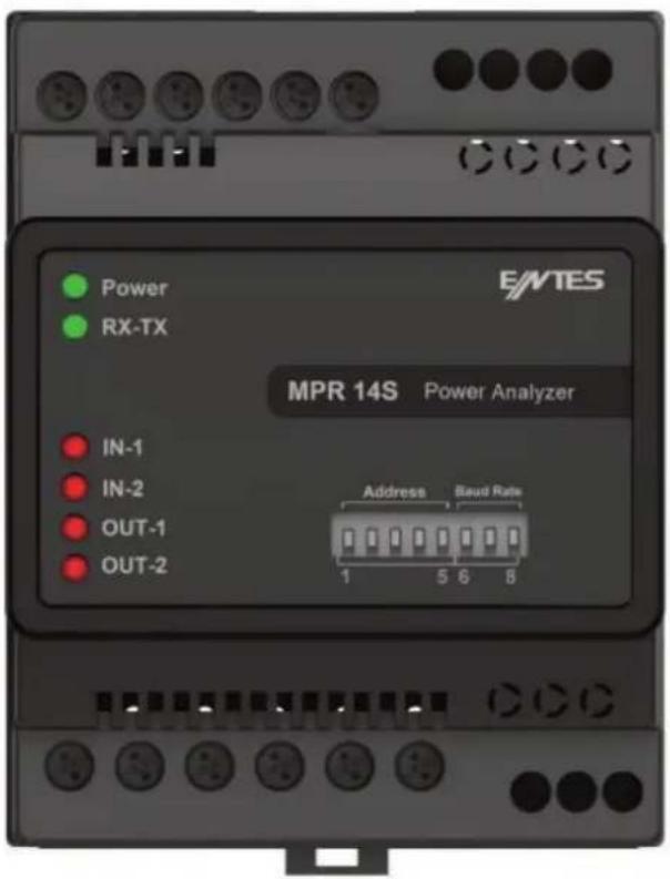
Appearance and Interface
The appearance of the device's front is as below:
Terminal Structures
The terminal structures according to the models are described in this section:
Structure of the MPR-14S Terminal:

Current Terminals: K1, L1, K2, L2, K3, L3
An external current transformer must be used for the 3-phase system connection to these terminals where the current up to 5A can be input.
Supply Terminals: A1, A2
Please, apply 95-270 VAC/DC (12-50 VDC for MPR-1X-D series) supply connection through these terminals.
Voltage Terminals: N, L1, L2, L3
Please, apply 3-phase voltage connection through these terminals.
Communication Terminals: A(+), B(-), GND, TR
RS-485 communication terminals are used for Modbus RTU communication connection. A (+) and B (-) terminals are connected in parallel between devices.
When the communication distance exceeds 10 meters and there are more than one device on the line, communication instability may occur. In this case;
- A 120 Ohm connection resistor from the device box is installed between the A (+) terminal and the B (-) terminal,
- Short circuit between the TR terminal and the A (+) terminal.
In this way, line balancing is done.
Structure of the MPR-15S-22 Terminal:
DOC terminals is referred to digital output common, digital output reference connection is done with this terminal.DO1 and DO2 is also referred to 1st and 2nd digital output terminals.
INC terminal is referred to Input Common and it is the digital input reference. IN1 and IN2 are also referred 1st and 2nd digital input terminals.

Digital Input Terminals: INC, IN1, IN2
As the INC terminal will be the joint point (reference), the IN1 and IN2 inputs are used as digital inputs between 5-30V. Inputs have 1kV insulation level.
Digital Output Terminals: OC, O1, O2
As the OC terminal will be the joint point (reference), the O1 and O2 terminals are used as insulated outputs. As it can be seen from the following figure, these Open Collector outputs should be fed by an external supply for operation.

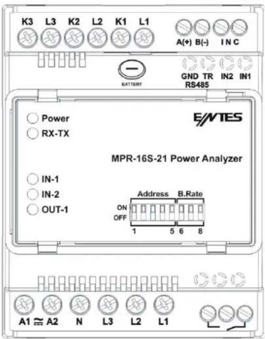
Structure of the MPR-16S-21 Terminal:
Different from the MPR-16S-21'den these terminals which are used for relay output are the terminals next to the voltage terminals. They are indicated with the key symbol on the front view. The terminal structure of the MPR16S-21 model is as in the following:
Digital Input Terminals: INC, IN1, IN2
As the INC terminal will be the joint point (reference), the IN1 and IN2 inputs are used as digital inputs between 5-30V. Inputs have 1kV insulation level.
Structure of the MPR-17S-23 Terminal:
As the AOC terminal will be the joint point (reference), the analogue current or voltage output is ensured respectively through the AIO and AVO terminals. Only one of the AVO and AIO terminals are used at the same time.

Analog Output Terminals: AOC, AVO, AIO
AOC terminal is the common point (reference), and analog current or voltage output is provided from the AIO and AVO terminals, respectively. Only one of the AVO and AIO terminals is used at the same time.
Digital Input Terminals: INC, IN1, IN2
As the INC terminal will be the joint point (reference), the IN1 and IN2 inputs are used as digital inputs between 5-30V. Inputs have 1kV insulation level.
Digital Output Terminals: OC, O1, O2
As the OC terminal will be the joint point (reference), the O1 and O2 terminals are used as insulated outputs. As it can be seen from the following figure, these Open Collector outputs should be fed by an external supply for operation.
CONNECTION TYPES
As there are shunts at the current measurement inputs of the device, it is mandatory to use a current transformer except for the connections of current inputs. If, the device will be used on the same current line by means of analyzers with other shunts, it is recommended that the device is located at the extreme point.
The device has 5 different connection types. These connection types are described in the following schemes:
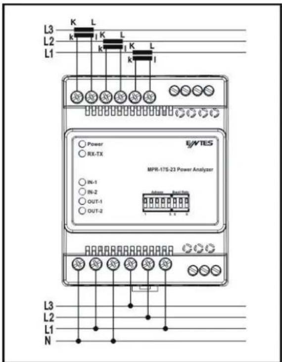
3P4W (Three-Phase Four-Wire) Connection
As it is seen below, four voltage and three current connections including the neutral line are established in this connection type.
3P3W (Three-Phase Three-Wire) Connection
As it is seen below, three voltage and three current connections are established in this connection type.

ARON Connection
Three voltage and two current connections are established in this connection type. As it is seen in the following figure, the current connections are established with the 1st and 3rd phases.

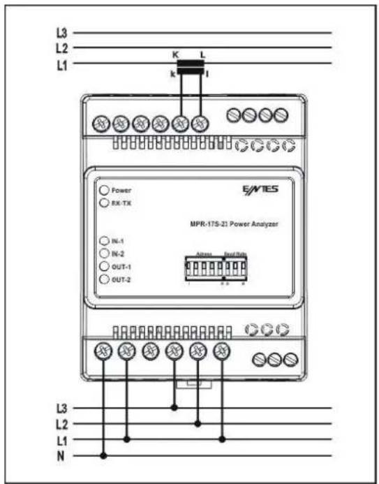
3P4W BLN (Three-Phase Four-Wire Balanced) Connection
Four voltages and one current connection are established in this connection type. The device displays the value measured at the current input connected to the first phase on its screen for other phases in the same value.

3P3W BLN (Three-Phase Three-Wire Balanced) Connection
Three voltage and one current connection are established in this connection type. As it is seen below, the device displays the value measured at the current input connected to the first phase on its screen for other phases in the same value.
Communication Line Termination Resistance
RS-485 communication terminals are used for Modbus RTU communication connection. A (+) and B (-) terminals are connected in parallel between devices. When the communication distance exceeds 10 meters and there are more than one device on the line, communication instability may occur. In this case;
- 120 Ohm line coming out of the device box between A (+) terminal and B (-) terminal. termination resistor installed,
- Short circuit between the TR terminal and the A (+) terminal.
In this way, line balancing is done.

Device Communication Settings
Device communication address and baud rate settings are adjustable from the DIP switches located at the device's front panel. Devices communication address settings can be done, as shown at the below table.
Number written to the Modbus 17124 address and the DIP switch's 1st and 5th positions determines the devices communication address. Factory settings for Modbus address is 1.
| Number written to Modbus 17124 address | DIP switch setting | Address |
| 1 10000 1 | ||
| 1 01000 2 | ||
| ... ... ... | ||
| 1 11111 31 | ||
| 32 00000 32 | ||
| 32 10000 33 | ||
| ... ... ... | ||
| 32 11111 63 | ||
| ... ... ... | ||
| 64 00000 64 | ||
| 64 10000 65 | ||
| 64 01000 66 | ||
| ... ... ... | ||
| 200 00000 192 | ||
| 200 10000 193 | ||
| 232 00000 224 | ||
| ... ... ... | ||
| 232 11101 247 |
Baud rate is determined from DIP switch's 6th, 7th and 8th pins as shown at the below.
| Baud rate |
| 000:2400 |
| 100:4800 |
| 010:9600 |
| 110:19200 |
| 001:38400 |
| 101:57600 |
| 011:115200 |
| 111:115200 |
Technical Information
| Technical properties Value | |
| Dimensions DIN 4 | |
| Voltage measurement range 10~300 VAC(VLN) 10~480 VAC(VLL) | |
| Measurement range with transformer 10V~999 kV | |
| Accuracy %0.5 ± 1 digit | |
| Input Impedance 1.8 MΩ | |
| Burden (Input Load) < 0.5 VA | |
| Current measurement accuracy %0.5 ± 1 digit | |
| Nominal Current 1A, 5A | |
| Lowest current 5 mA | |
| Current measurement range 50 mA ~ 5,5A (Do not use without current transformer) | |
| Measurement range with transformer 50 mA ~ 10 kA | |
| Burden (Input Load) < 1 VA | |
| Active power accuracy %1 ± 1 digit | |
| Reactive power accuracy %1 ± 1 digit | |
| Active energy measurement accuracy | Class 1 |
| Reactive energy measurement accuracy | Class 2 |
| Active power measurement range | 0 ~ 1 GW |
| Reactive power measurement range | 0 ~ 1 GVAr |
| Apparent power measurement range | 0 ~ 1 GVA |
| Power consumption | < 4 VA |
| Active energy measurement ceiling | 9 999 999.9 kWh |
| Reactive energy measurement ceiling | 9 999 999.9 kVArh |
| Operating voltage | 95 - 270 VAC/VDC ,12 – 50 VDC (MPR-1X-D)(Tolerances up to ± 10%) |
| Operating frequency | 45 - 65 Hz. |
| Max. Voltage / Max. Current (For Relay) | 250 VAC / 5A |
| Digital input processing voltage | 5 ~ 30 VDC |
| Digital input switching current | Max 50 mA |
| Minimum pulse time 100 ms pulse period, 80 ms pulse width | |
| Operating Temperature Range | -10 ~ +70 °C |
| Storage Temperature Range | -20 ~ +80 °C |
| Maximum operating humidity | 95 % |
| Assembly | Assembled to the wall box from the front. |
| Connection terminals | Screw terminal |
| Connection types | 3 phase without neutral (3P3W)3 phase + neutral (3P4W)3 phase without neutral (3P3W) balanced3 phase + neutral (3P4W) balanced3 phase Aron |
| Communication Protocol | RS-485 / MODBUS RTU |
| Communication Speed | 2400 ~ 115200 bps |
| CONFORMITY IEC 61557-12 Edition 2 | ||
| PMD SPECIFICATIONS | ||
| Type of Specification Examples of | possible specification values | Other additional specifications |
| Supply quality evaluation function (option) | / | / |
| PMD Classification SD / | ||
| Set point K55 / | ||
| Humidity + Altitude // | ||
| Operating performance class for active power or active energy (if function available) | 0,5 / | |
| Symbol for functions | Measurement range | Operating performance class, according to CEU 61557-12 according to KI | Other additional specifications |
| P 10% to 120% In 0,5 | |||
| Qa, Qv 10% to 120% In 1 | |||
| Sa, Sv 10% to 120% In 1 | |||
| Ea 0 to 9999 9999 kW/h 0,5 | |||
| Era, Erv 0 to 99 999999 kVar/h 1 | |||
| Eapa | 0 to 99999999 kVA/h | 0,5 | |
| f | 45 to 65 Hz | 0,02 | |
| I | 10% to 120% In 0,2 | ||
| In, Inc | 10% to 120% In 0,2 | ||
| U | 10 to 520Vac ph/ph 0,2 | ||
| Pfa, Pfv | 0,5 ind to 0,8 cap | 0,5 | |
| Udip, Uswl | Unavailable function | ||
| Utr | Unavailable function | ||
| Uint | Unavailable function | ||
| Unba, Unb | Unavailable function | ||
| Uh | Unavailable function | ||
| THDu | Fn=50Hz - range 1 to 50 Fn=60Hz - range 1 to 50 | 1 | |
| THD-Ru | Unavailable function | ||
| Ih | Unavailable function | ||
| THDi | Fn=50Hz - range 1 to 50 Fn=60Hz - range 1 to 50 | 1 | |
| THD-Ri | Unavailable function | ||
| Msv | Unavailable function | ||
Compliance with the Standards
| Standard Year Title | |
| IEC 61557-12 2008 Electrical safety in low voltage distribution systems up to 1kV (a.a.) and 1,5kV DC(d.a.) - Equipment for testing, measuring or monitoring of protective measures - Part 10: Performance measuring and monitoring arrangements | |
| IEC 61326-1 2005 Electrical equipment for measurement, control and laboratory use - EMC requirements - Part 1: General conditions | |
| EN 61000-6-2 2005 Electromagnetic compatibility (EMC) - Part 6-2: General standards - Immunity for industrial environments | |
| IEC 60050(161) | 2011 International Electro-technical Vocabulary Chapter 161-Electromagnetic Compatibility |
| EN 62053-21 2003 Electrcity measurement equipment (a.a.) - Special rules - Chapter 21: Static meters for active energy (class 1 and class 2) | |
| EN 62053-23 2003 Electrcity measurement equipment (a.a.) - Special rules - Chapter 23: Static meters - Reactive energy (class 2 and class 3) | |
| EN 61000-4-2 1995 Electromagnetic compatibility (EMC) - Part 4-2: Test and measurement techniques - Electrostatic discharge immunity test | |
| EN 61000-4-3 2006 Electromagnetic compatibility (EMC) - Part 4-3: Test and measurement techniques-Radiated, radio- frequency, electromagnetic field immunity test | |
| EN 61000-4-4 2004 Electromagnetic compatibility (EMC) - Part 4-4: Test and measurement techniques - Electrical fast transient/burst immunity test | |
| EN 61000-4-5 2006 Electromagnetic compatibility (EMC) - Part 4-5: Test and measurement techniques - Surge immunity test | |
| EN 61000-4-6 2007 Electromagnetic compatibility (EMC) - Part 4-6: Test and measurement techniques - Immunity to conducted disturbances, induced by radio-frequency fields | |
| EN 61000-4-8 2010 Electromagnetic compatibility (EMC) - Part 4-8: Test and measurement techniques-Power Frequency Magnetic Field Immunity Test | |
| EN 61000-4-11 2004 Electromagnetic compatibility (EMC) - Part 4-11: Test and measurement techniques - Voltage dips, short interruptions and voltage variations immunity tests | |
| EN 61000-6-3 2 | 2007 Elect | omagnetic compatibility (EMC) - Chapter 6-3: General standards - Emission Standard for residential, Commercial and light-industrial environments |
| EN 61000-3-2 2 | 2010 Elect | omagnetic compatibility (EMC) - Part 3-2: Limit values - limits for harmonic current emissions (equipment input current ≤ 16 A per phase) |
| EN 61000-3-3 2 | 2011 Elect | omagnetic compatibility (EMC) - Part 3-3: Limits - Limitation of voltage fluctuations and flicker in low- voltage supply systems for equipment with rated current kleiner 16 A |
| EN 55016-2-1 2 | 2009 Spec | fication for radio disturbance and immunity measuring apparatus and methods - Chapter 2-1: Methods of measurement of disturbances and immunity - Conducted disturbance measurements |
| EN 60068-2-2 | 2008 Basic | environmental testing procedures Part 2:tests-Test B: Dry heat |
| EN 60068-2-6 2 | 2007 Environ | nment test - Chapter 2-6: Tests - Fc tests: Vibration (sinus formed) |
| EN 60068-2-30 | 2008 Environ | vironmental testing -- Part 2-30: Tests - test db: Damp heat, cyclic (12 h + 12 h cycle) |
| EN 60068-2-31 | 2010 Environ | vironmental testing -- Part 2-31: Tests - test ec: Rough handling shocks, primarily for equipment-type specimens |
| EN 60068-2-75 | 1997 Basic | Environmental Testing Procedures Part 2: Tests - test eh: Hammer tests |
| BS EN 61010-1 | 2010 Safety | requirements for electrical equipment for measurement, control and laboratory use-Part 1:General requirements |
| EN 61010-2-030 | 2010 Safety | requirements for electrical equipment for measurement, control and laboratory use-Part 2-030: Specific rules for test and measurement of circuits |
| EN 62262 2010 | Degrees | of protection provided by enclosures for electrical equipment against external mechanical impacts (IK code) / Note: Includes Corrigendum of July 2002 (EN 50120 + A1 are renumbered as EN 62262:2002) |
ENTES Elektronik Cihazlar Imalat ve Ticaret A.S.
Adr: Dudullu OSB; 1. Cadde; No:23 34776
Umraniye - ISTANBUL / TURKIYE
Tel: +90 216 313 01 10 Fax: +90 216 314 16 15
E-mail: contact@entes.eu Web: www.entes.eu
Call Center Technical Support: 0850 888 84 25
- Index
- SAFETY AND WARNING....3
- OPERATING CONDITIONS 4
- INTRODUCTION 5
- CONNECTION TYPES.... 12
- TECHNICAL INFORMATION AND ATTACHMENTS.... 17
- Attention
- Safety
- Guarantee
- OPERATING CONDITIONS
- General Specifications
- Applications
- MPR-1 Product Family
- Appearance and Interface
- Terminal Structures
- Structure of the MPR-14S Terminal:
- Supply Terminals: A1, A2
- Voltage Terminals: N, L1, L2, L3
- Communication Terminals: A(+), B(-), GND, TR
- Structure of the MPR-15S-22 Terminal:
- Digital Input Terminals: INC, IN1, IN2
- Digital Output Terminals: OC, O1, O2
- Structure of the MPR-16S-21 Terminal:
- Structure of the MPR-17S-23 Terminal:
- Analog Output Terminals: AOC, AVO, AIO
- CONNECTION TYPES
- 3P4W (Three-Phase Four-Wire) Connection
- 3P3W (Three-Phase Three-Wire) Connection
- ARON Connection
- 3P4W BLN (Three-Phase Four-Wire Balanced) Connection
- 3P3W BLN (Three-Phase Three-Wire Balanced) Connection
- Communication Line Termination Resistance
- Device Communication Settings
- Compliance with the Standards
Brand : ENTES
Model : MPR-16S-21-D
Category : Analyseur réseau