GEM-10SH - Electric meter ENTES - Free user manual and instructions
Find the device manual for free GEM-10SH ENTES in PDF.


| Product Type | Energy Analyzer / Power Quality Analyzer |
| Brand | ENTES |
| Model | GEM-10SH |
| Dimensions (H x W x D) | 96 x 96 x 90 mm (panel mount) |
| Weight | Approx. 0.5 kg |
| Power Supply | 85-265 V AC/DC, 50/60 Hz |
| Display | High-contrast backlit LCD |
| Measurement Parameters | Voltage, current, power, energy, power factor, frequency, harmonics |
| Measurement Accuracy | Class 0.5 (voltage/current), Class 1 (power/energy) |
| Communication | RS485 Modbus RTU (optional Ethernet via external module) |
| Sampling Rate | 256 samples/cycle |
| Harmonics Analysis | Up to 31st harmonic |
| Data Logging | Internal memory for up to 1 year of daily data |
| Environmental Protection | IP54 (front panel), IP20 (enclosure) |
| Operating Temperature | -10°C to +55°C |
| Storage Temperature | -25°C to +70°C |
| Humidity | 5% to 95% (non-condensing) |
| Safety Standards | IEC 61010-1, CAT III 300V |
| Installation | Panel mount, 96x96 mm cutout |
| Maintenance | Clean with dry cloth; no user-serviceable parts inside |
| Spare Parts / Repairability | Contact ENTES support; device not field-repairable |
| Included Accessories | Mounting brackets, terminal connectors, quick start guide |
| Warranty | 2 years |
Frequently Asked Questions - GEM-10SH ENTES
User questions about GEM-10SH ENTES
0 question about this device. Answer the ones you know or ask your own.
Ask a new question about this device
Download the instructions for your Electric meter in PDF format for free! Find your manual GEM-10SH - ENTES and take your electronic device back in hand. On this page are published all the documents necessary for the use of your device. GEM-10SH by ENTES.
USER MANUAL GEM-10SH ENTES
1.1 General Specifications.... 5
1.2 Technical Specifications .... 5
1.3 Connection Diagram.... 6
1.4 LED Functions.... 7
- Installing Drivers.... 7
2.1 Installing Drivers for Windows 7 7
2.2 Installing Drivers for Windows 8.1 10
2.3 Installing Drivers for Windows 10 14
3.Configuration 18
3.1 Connection Settings 19
3.1.1 TCP Connection Type....19
3.1.2 Operating Mode....19
3.1.3 ModbusTCP Port 19
3.1.4 TCP Timeout....19
3.1.5 Connection Type....19
3.1.6 Server IP 20
3.2 Ethernet Settings (This setting is not found on the GEM-05 model) 20
3.2.1 DHCP 20
3.2.2 IP Address 20
3.2.3 Gateway....20
3.2.4 Subnet Mask....20
3.2.5 MAC ID 20
3.2.6 WEB Configuration 20
3.2.7 WEB Port....21
3.2.8 Web Process Timeout....21
3.2.9 Password....21
3.3 GPRS Settings ( Available only on GEM series) 21
3.3.1 Username 21
3.3.2 Password 21
3.3.3. APN 21
3.3.4 Keep-Alive Range.... 21
3.3.5 Number of Failed Keep-Alives 21
3.3.6 Connection Latency 21
3.5 Software Update.... 23
3.6 Device Information.... 23
-
Sample Configuration for Remote Network Connection via Modem 25
-
EMG/GEM/MY GEM/MY EMG Product Comparison 26
-
Maintenance 26
-
Warranty Terms 27
9.Conformity Data.... 27

Copyrights of this manual are reserved and it is strictly prohibited to use any part or content of it.
Read and follow this manual carefully before commissioning and operating ENTES EMG&GEM. The information given below is important to avoid problems that may emerge during installation and use.
Please contact the manufacturer for all technical notices: contact@entes.eu
Safety Warnings
- Installation, commissioning, maintenance and operation of the product must be carried out by authorized specialists.
- The manufacturer is not responsible for damages emerging from failure to follow the instructions.
- Do not install the product if it has been damaged during transportation. Contact your Sales Representative.
- Do not dismantle or try to fix the product. The product has no user-serviceable parts.
- In case of a failure, immediately contact the authorized company.
- Do not operate the product at low voltages.
- Do not use this product for purposes other than those described in the user manual.
- Check the connections before supplying power to the product.
- Do not touch the terminals while the product is powered.
1. Introduction
1.1 General Specifications
ENTES EMG/GEM Modbus Gateway range is a Modbus TCP/Modbus RTU protocol converter that uses the TCP/IP protocol to ensure remote control of your devices, which communicate through RS485 with the Modbus protocol, through the existing internet/internet infrastructure.
General Specifications of EMG/GEM Series Devices:
• Cinterion MC55i Quad-band GPRS modem (GEM series only).
• 10/100 Mbps Ethernet port (EMG&GEM).
• RS232 (EMG&GEM), RS485 port (1200...115200 bps).
- Mini USB port for configuration.
- Operation with SIM cards that have a static or dynamic IP (GEM series only).
- Ability to use the Ethernet port to set device parameters through WEB. (EMG&GEM).
- Ability to work as a server or client.
- Ability to work in Modbus TCP or Transparent mode.
- Ability to read predefined counter data (GEM-10SH only).
• GSM port (GEM series only).
EMG&GEM devices are configured as default. There is no need to configure said products. Follow the steps below in order for the installation of your devices.
1) Establish the ModBus connection of the device.
2) Insert SIM card (MY GEM-02 only).
3) Supply power to the device.
1.2 Technical Specifications
| Category Description | |
| Network Protocols TCP/IP, ARP, | ICMP, HTTP*, ModbusTCP |
| Serial Ports RS232 (EMG&GEM), | RS485 port (1200...115200 bps) USB port for configuration |
| Operating Modes | Modbus TCP/RTU, Transparent and Meter Reading (GEM-10SH) |
| Network Interface 10/100 Mbps auto-negotiation | |
| Serial Communication Formats Data bits: 5-6-7-8Stop Bit: 1-1.5-2 characterParity: Single-double-none | |
| Serial Interface 1200-115200 bps | |
| Supply 12-20V DC | |
| Insulation and protection RS485 | port: 500VEthernet port: 1500V (not available on GEM-05) 15KV ESD protection on the USB port10/1000 us (600W) transient pulse protection on the RS485 port |
Table 1: Technical Specifications of EMG/GEM Devices
1.3 Connection Diagram

RS232
Figure 1: EMG/GEM Connection Diagram

* Use a thin apparatus, slightly press the button next to the SIM card slot, insert the card into the slot and put the slot in place.
* Make sure that the SIM card does not have a card code and cut off the supply voltage of the device before inserting the card.
1.4 LED Functions
Signal functions of the device can be tracked through the LEDs found on the front surface of your device.
| POWER GSM GPRS | LINK (not available on GEM-05) | |||
| Green Not ready | - Connected to | GPRS Ethernet Link | ||
| Red Ready --- | ||||
| Red (flash) - Connecting to GSM | ||||
| Red - Green | - | Signal level | - | - |
| Green (flash) | - | - | - | Ethernet Data |
Table 2: EMG/ GEM LED Functions
Link/Act: It indicates that the Ethernet connection has been established successfully.
Serial / Data / GPRS: Different names are used on different devices. There are different functions according to these names.
Serial indicates the existence of serial communication for EMG devices.
GPRS indicates that the GPRS connection has been established for the GEM series.
Data indicates the existence of serial communication for MY EMG-02.
GSM: GSM connection is found on EMG&GEM
POWER: Device power indicator.

natural_image
Pattern of alternating red and green circles arranged in a triangular formation (no text or symbols)Signal level is perfect
Signal level is good
Signal level is moderate
Signal level is low
Signal level is very low
Table 3 : LED Signal Level
2. Installing Drivers
Since the configuration software of EMG/GEM products communicates through the USB port, please visit http://www.entes.com.tr/kd-detay.asp?KatID=61 to install device drivers on your computer before using the device
2.1 Installing Drivers for Windows 7
Please follow the steps below to install the drivers on Windows 7 operating system.
1st Step Establish the electrical connections of the device according to the connection diagram and supply power to the device.
2nd Step Select Start-> Control Panel -> System and Security-> System.
3rd Step On this page, from the "System" bottom units, select "Device Manager" submenu (Figure 2).

Figure 2: Windows 7- Device Manager
4th Step On the "Device Manager" page, under "Other Devices", you will see the name of the device that is connected to the computer. It is not active in this stage since the computer will not know your device. Right click on "ENTES GPRS MODEM" shown in the figure and select "Update Software" (Figure 3).
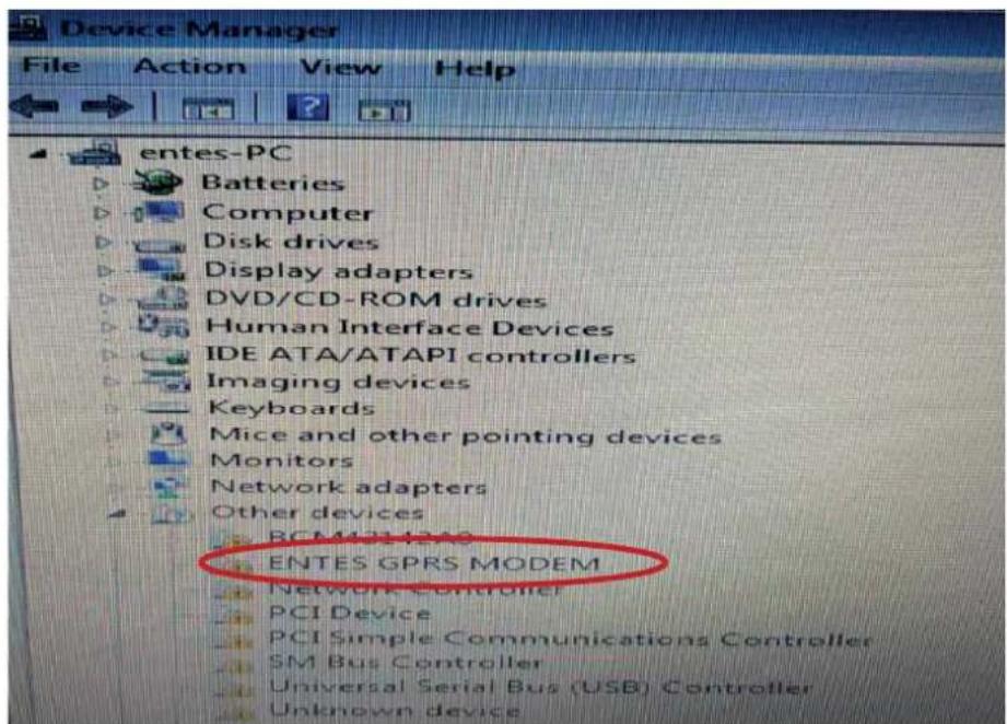
Figure 3: Windows 7 - Activating the Device
5th Page On this page, select "Browse my computer for driver software" to proceed (Figure 4).

Figure 4: Windows 7 - Finding Drivers
6th Step Click "Browse...", select the file that contains the installation index on your computer and click "Next" to proceed(Figure 5).
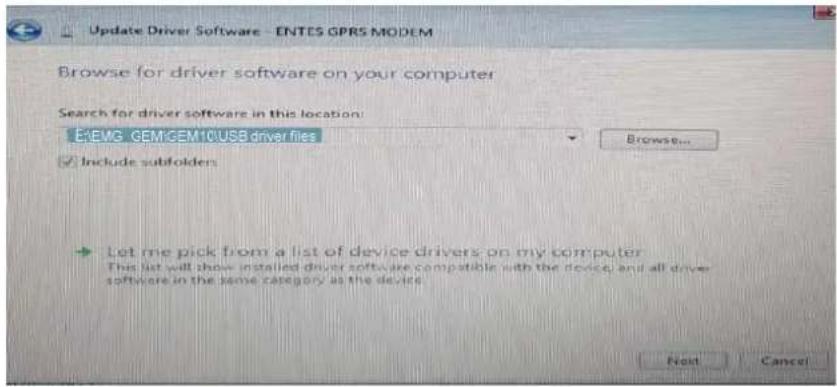
Figure 5: Windows 7 - Installing Drivers
7th Step Your computer will start installing device drivers. Once you see “Windows has finished installing the driver software for this device” click “Close” to complete the installation process (Figure 6).
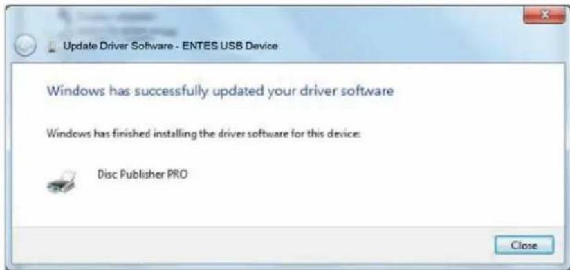
Figure 6: Windows 7 - Completing the Driver Installation Process
8th Step Go to the "Device Manager" window. Under "Universal Serial Bus Controllers" you will see that your device is active (Figure 11).

Figure 7: Windows 7 - Registering the Device on the Computer
2.2 Installing Drivers for Windows 8.1
On computers with Windows 8.1 OS, the following system settings must be performed respectively before establishing the computer connections of EMG and GEM devices
1st Step In the "Start" menu of the computer, click ⏻ at the bottom of the screen to launch the "Applications" menu.
2nd Step Under the “Applications” menu, proceed to “PC Settings” submenu and select “Update and recovery” (Figure 8).
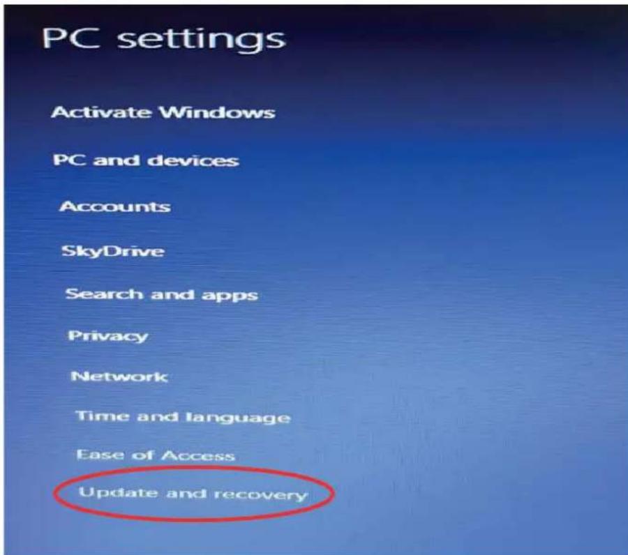
Figure 8: Windows 8.1–PC settings
3rd Step Step In the "Update and recovery" menu, select "Recovery". On the "Advanced Startup" page on the right side, select "Reboot Now" icon. Your computer will restart, please wait (Figure 9).

Figure 9: Windows 8.1 - Update and Recovery
4th Step On the screen you see once you've rebooted the computer, select "Troubleshoot" and on this page go to "Advanced Options". (Figure 10)
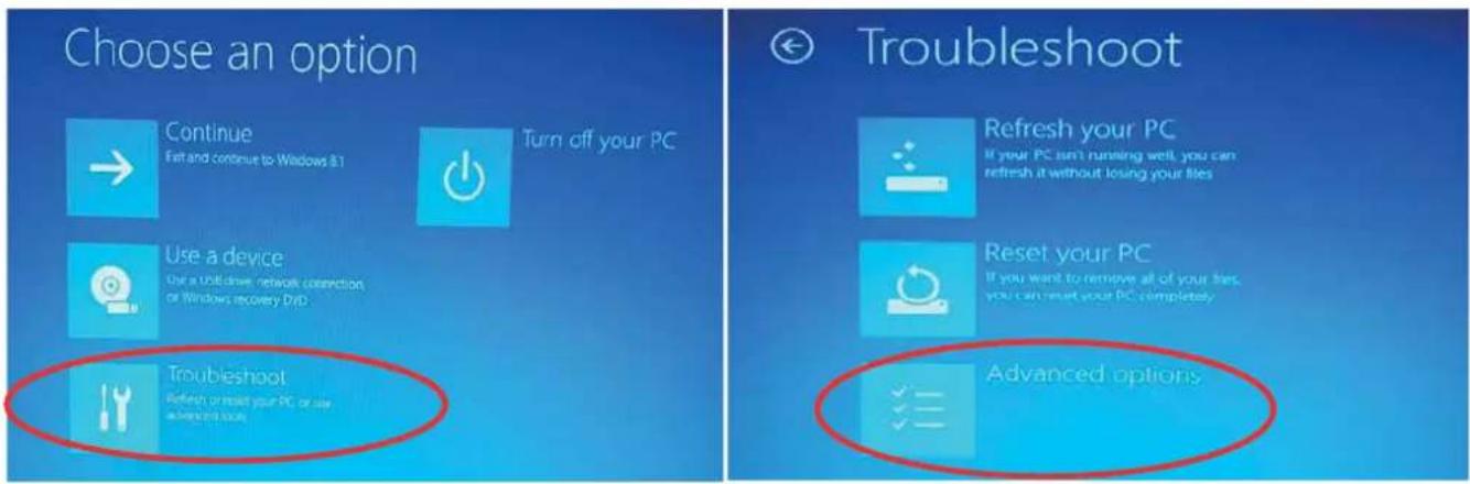
Figure 10: Windows 8.1 -Troubleshoot
5th Page On the "Advanced Options" page, proceed to the menu "Startup Settings" (Figure 11). On the "Start Settings" page, select the "Reboot" icon on the bottom right corner. Your computer will restart, please wait.

Figure 11: Windows 8.1 - Advanced Options
6th Step Once your computer has restarted, you will see the page where you will make the final settings for installation. Press F7 on the keyboard to select "Disable Driver Signature Enforcement" (Figure 12). Your computer will restart, please wait.

Figure 12: Windows 8.1 – Startup Settings
7th Step Once your computer has restarted, proceed to Computer->Properties->Device Manager menus respectively (Figure 13 & Figure 14).
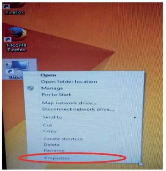
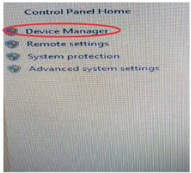
Figure 13: Windows 8.1 – Properties Figure 14: Windows 8.1 – Device Manager
8th Step On the "Device Manager" window, under the option "Other Devices", you will see the name of your EMG and GEM device connected to the computer, with an exclamation mark on it. It is not active in this stage since the computer will not know the hardware. Right click on the device name shown in the figure and select "Update Driver Software".

Figure 15: Windows 8.1 – Other Devices
9th Step On the "Update Driver Software" page, select "Browse my computer for driver software".
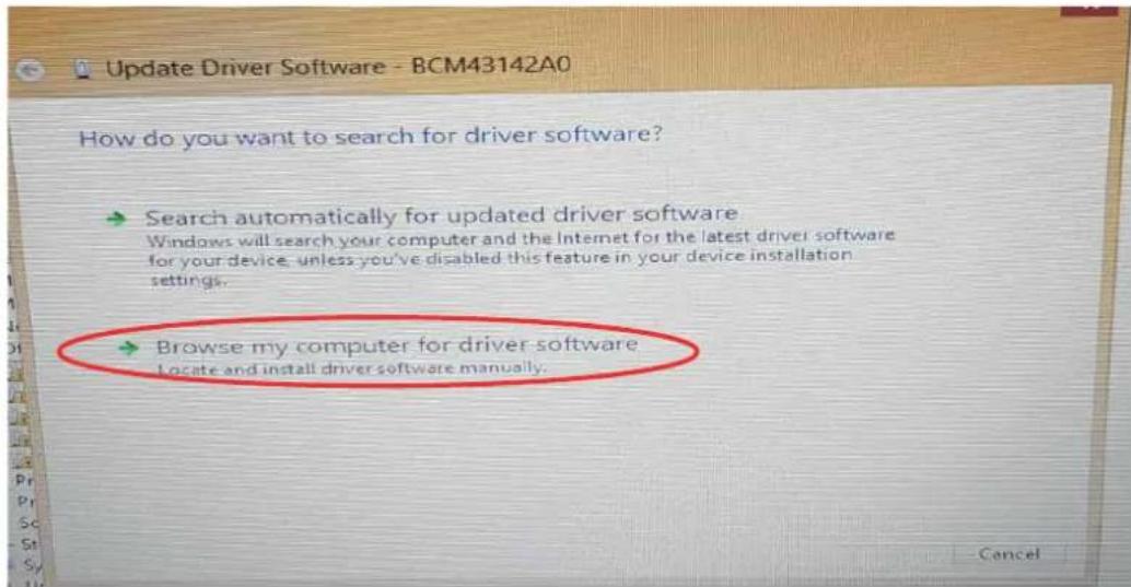
Figure 16: Windows 8.1 – Update Driver Software
10th Step On this page, select "Browse", find the driver software and click "OK". For the driver whose location you've indicated to be installed, press "Next".
11th Step Once the device drivers have been installed, you will see the "Device Manager" page. Under the option "Universal Serial Bus Controllers", you will see the name of your EMG or GEM device.

Figure 17: Windows 8.1 - Registering the Device on the Computer
2.3 Installing Drivers for Windows 10
On computers with Windows 10 OS, the following system settings must be performed respectively before establishing the computer connections of EMG and GEM devices.
1st Step On your computer, enter the "Settings" menu found in the "Windows Icon" (Figure 18).

Figure 18: Windows 10 – Settings
2nd Step On the "Settings" page, select Update & security->Recovery -> Advanced Startup -> Restart now respectively (Figure 19s).
3rd Step To go the "Startup Settings" page, click the "Troubleshoot & Advanced Options" respectively. Your computer will restart, please wait.


Figure 19-1: Windows 10 – Update Recovery Figure 19-2: Windows 10 – Recovery & Restart now


Figure 19-3: Windows 10 - Troubleshoot Figure 19-4: Windows 10 – Advanced Options

Figure 19-5: Windows 10 – Startup Settings
4th Step Once your computer has restarted, you will see the page where you will make the final settings for installation.
Press F7 on the keyboard to select "Disable Driver Signature Enforcement". Your computer will restart, please wait (Figure 20).

Figure 20: Windows 10 - Start
5th Step On your computer, which has just been rebooted, apply the steps below respectively (Figure 21).
Computer → Properties → Device Manager
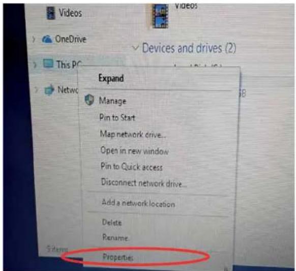
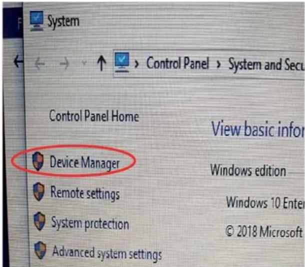
Figure 21-1: Windows 10 - Properties Figure 21-2: Windows 10 - Device Manager

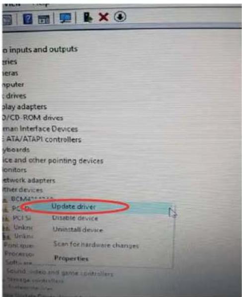
Figure 21-3: Windows 10 – Update Driver Software

Figure 22: Windows 10 – Updating Steps
6th Step On the "Device Manager" window, under the option "Other Devices", you will see the name of your EMG and GEM device connected to the computer, with an exclamation mark on it. It is not active in this stage since the computer will not know the hardware. Right click on the device name shown in the figure and select "Update Driver Software". Click "Browse my computer for driver software" (Figure 22).
7th Step On this page, go to the "Browse" icon, find the page that contains driver files and click the "OK" icon. Click "Next" so that the software whose location you've indicated can be found by the computer.
8th Step Once your computer gives a warning about "Windows Security", select "Install this driver software anyway".
Your computer will continue installing relevant program drivers.
10th Step Once you see the warning "Windows has finished installing the driver software for this device:", click the "Close" icon to complete the installation process. Once the installation process is complete, the "Device Manager" page will open automatically.
Under the option "Universal Serial Bus Controllers", you will see the name of your EMG or GEM device (Figure 23).

Figure 23: Windows 10 - Registering the Device on the Computer
3.Configuration
For the device to work, both serial communication parameters and network settings must be correct. Missing or incorrect settings may negatively affect the system performance, as well as damaging the existing communication infrastructure. Besides, your EMG/GEM device will work with factory defaults in first use.
| Connection TCP | P Connection Type TCP S | Server (EMG&GEM) |
| Operating Mode Modbus | TCP (Counter reading: GEM-10SH) | |
| ModbusTCP TCP Port : | 502 | |
| TCP Timeout: 120 | ||
| Server IP : 0.0.0.0. | ||
| Connection Type GPRS | for the GEM Series (this setting is not found on EMG Series) | |
| Ethernet (This setting is not found on GEM-05) | DHCP Active Passive (Active MY EMG-02) | |
| IP Address 192.168.2.248 | ||
| Gateway 192.168.2.1 | ||
| Subnet Mask 255.255.255.0 | ||
| MAC ID It must be the same as the MAC ID found on the product's packaging and the cardboard box. | ||
| Web Configuration Active | ||
| Web Port 80 | ||
| WEB Process Timeout 120 | ||
| Web Password Model name of each device | ||
| Serial Port | Serial Port | RS485 |
| Baudrate | 9600 | |
| Stop Bit 1 | ||
| Parity | None | |
| Serial Timeout | 200 | |
| Modbus Latency | 20 | |
| Retry | 3 (GEM-10SH only) | |
| GPRS (GEM Series only) | Username | Username |
| Password | password | |
| APN | mgbs | |
| Keep Alive Range | 1 | |
| Number of Failed Keep- Alives | 3 | |
| Connection Latency | 15 | |
Table 4: Factory Settings of EMG/ GEM Devices
3.1 Connection Settings


Figure 24: EMG Series - Connection Menu Figure 25: GEM Series - Connection Menu
3.1.1 TCP Connection Type
You can operate your EMG/GEM device in the server or client mode. If you want to connect your EMG/GEM device remotely, select the "TCP Server". If the server to be connected is the one determined by the user, select "TCP Client"
3.1.2 Operating Mode
The device has two types of operating modes. ModbusTCP - RTU and Transparent Mode. If you want to convert ModbusTCP packets into Modbus RTU, you need to set the operating mode to ModbusTCP – RTU. If you want the packets received through TCP to be sent to the serial line without being subject to any protocol conversion, you need to set the operating mode to Transparent. For GEM-10SH, if it is to be used for the counter reading function according to the standard IEC62056-21, select “Counter Reading” from the menu.
Counter reading function is found on the GEM10-SH model only.
3.1.3 ModbusTCP Port
It indicates the port number to be used for ModbusTCP.
3.1.4 TCP Timeout
If the device has been set as a server, this value indicates in seconds the time that the device will wait to refresh the GPRS connection in case of no data exchange.
3.1.5 Connection Type
In this section, you can select the interface where the ModbusTCP communication will take place. If you select Ethernet/GPRS, GEM will try to connect to the server via Ethernet first. In case of failure, it will try to access the server's IP address through GPRS. After the GPRS connection has been established, GEM-10 will continue to send Ping request to the Server at 5 second intervals through the Ethernet. If it receives response for 4 ping requests consecutively, the GPRS will be disconnected and the connection will be redirected to Ethernet. This setting means something only if the device has been set as a client.

This function is found only on the GEM series.
3.1.6 Server IP
If the GEM-10 has been set as a client, this section indicates the IP address to be connected to.
3.2 Ethernet Settings (This setting is not found on the GEM-05 model)
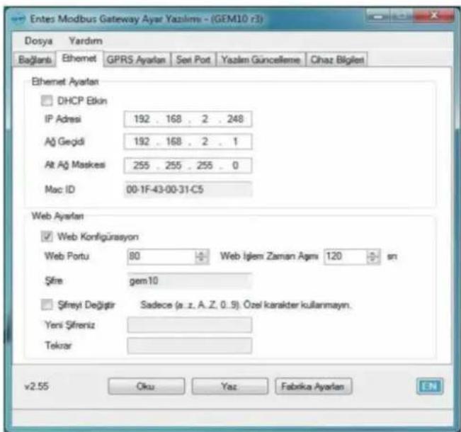
This function is not found on GEM-05 or MY EMG-02 models.
Access to the WEB interface of GEM10 is only possible through the Ethernet port.
3.2.1 DHCP
It indicates that your EMG/GEM device will receive the IP address for the Ethernet connection over a DHCP server. If your system does not have a DHCP server, please disable this option.
3.2.2IPAddress
It shows the IP address your device will use for Ethernet connection. If the device receives the IP address over DHCP, this area will show the IP address assigned by the DHCP server.
3.2.3 Gateway
It shows the address of the gateway or modem through which the device is connected to internet.
3.2.4 Subnet Mask
It shows the network address to which the device is connected.
3.2.5 MAC ID
It shows the MAC address of the device.
3.2.6 WEB Configuration
Enable this setting if you want to be able to change the settings of the device through the WEB interface.
3.2.7 WEB Port
Here you can set the port number to be used for WEB access.
3.2.8 Web Process Timeout
If the WEB page is closed without pressing the exit button, the device will make the user's log-in invalid after the specified time has passed.
3.2.9Password
To change the password used for WEB access, enable the option "Change Password" and enter the new password.
3.3 GPRS Settings ( Available only on GEM series)
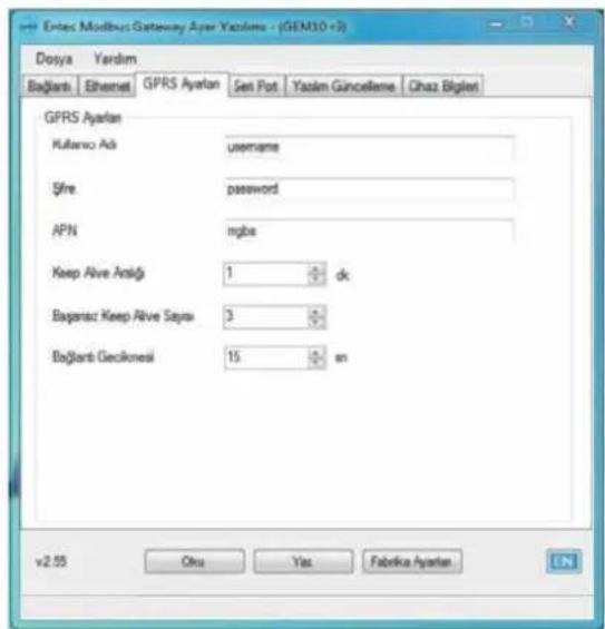
Please contact your GSM operator to find out the GPRS Username, Password and APN Name.
3.3.1 Username
Enter the username to be used for the GPRS connection.
3.3.2 Password
Enter the password to be used for the GPRS connection.
3.3.3. APN
Enter the APN name defined by the GSM operator for GPRS connection.
3.3.4 Keep-Alive Range
It indicates the range of keep-alive packets to be sent so that the GPRS connection is not ended by the GSM operator.
3.3.5 Number of Failed Keep-Alives
If the EMG/GEM cannot receive response for keep-alive packets of the indicated number, it will refresh the GPRS connection.
3.3.6 Connection Latency
When the EMG/GEM is set as a client, it indicates the frequency with which the device will try to connect to the server (tracepoint).
Figure 28: GEM Series - Serial Port Menu
3.4.1 Serial Port
It indicates the serial port you will use for communication. The RS232 port does not support handshake. If you are going to communicate with devices that use the Modbus protocol on your line, select RS485 from this box. The RS232 port is found only on EMG-02/12, MY EMG-02 and GEM-10SH models.
3.4.2 Baud Rate
It indicates the serial communication rate of your device.
3.4.3 Data Bit
It indicates how many bits the serial data packets are comprised of. Supported bit numbers are 5, 6, 7 and 8.
3.4.4 Stop Bit
Stop bit comes after data and parity bits on serial communication protocols, and it indicates that the data packet has ended. Supported stop bit numbers are 1, 1.5 and 2.
3.4.5 Parity Bit
These are parameters used to test the accuracy of data packets.
3.4.6 Serial Timeout
It indicates the time for which the response will be waited for from the device queried.
3.4.7 Modbus Latency
In case of tracing from more than one point, EMG will wait for the specified time before it sends each query it receives over TCP to the serial port. This time may change depending on the properties of the device to be queries. It indicates the time for which the incoming query will wait before being sent to RTU.
3.4.8 Retry
This setting indicates the number of retries to be done for OBIS queries for which a response could not be received during counter reading. It is applicable only in the counter reading mode (for GEM-10SH only).
3.5 Software Update

Figure 29: GEM Series - Software Update Menu
On the EMG/GEM device, you can install software updated on this tab. To do so:
- Click Open to open the file to be installed.
- Click Update to start updating the device. After the device has been reset, it will start loading the file specified.
- Once the updating process is complete, the device will reset itself and start working again.
• After the update, your device will continue working with the existing settings.
3.6 Device Information
This tab contains details about hardware/software versions of the device. Moreover, in the modem details section, you can see the device's status of connection to GSM, the GSM signal level, and you can watch the GPRS IP address of the modem. Details regarding GSM are available only on the GEM series.

Figure 30: GEM Series - Device Details Menu
NOTE: You need to cut the power supply to the device and reset the device for the changes to be active.
4. Accessing Device Settings Through WEB Interface
EMG/GEM has an HTTP server that allows you to remotely change the device's settings. This way, you can change the settings of your devices on the site without having to go there. If you want to reach the device settings through WEB, first of all, enable the "WEB Configuration" setting found in the "Ethernet" tab in the configuration program. The web interface is supported only on the Ethernet port. Web interface is not supported on GEM-05 or MY EMG-02 devices.
To access device settings:
I. In the address bar of your browser, type the IP address of your GEM/EMG.
If you want to change a setting, make the necessary changes and press "Update". After finishing all the adjustments, select "Save Settings" from the menu.

Figure 31: Device IP Address
II. On page you will see, type the WEB access password of the device (please contact the sales representative to find out the factory default password).

Figure 32: Web Access Password
III. You can use the menus on the left to access device settings.

Figure 33: Web Interface Page
Once the changes you've made have been saved in the permanent memory, the device will reset itself and start working again. Meanwhile, your Ethernet connections will be ended.
5. Sample Configuration for Remote Network Connection via Modem
There is an application that shows how you can use the EMG/GEM Ethernet-Modbus Gateway to access your serial devices connected to a remote network. The application program works with IP address 192.168.2.12. EMG/GEM is found on the subnet at the IP address 88.247.188.31 on the remote network. To remotely access the Modbus Gateway, necessary redirections must be done on the modem it is connected to. Also on EMG, 192.168.2.1 must be entered. It is the local network address of the ADSL modem installed as the Default Gateway address.

flowchart
graph TD
    A["Application Program"] --> B["Internet"]
    B --> C["Default Gateway 192.168.2.1"]
    B --> D["IP Subnet 192.168.2.10"]
    B --> E["Gateway 256.255.255.9"]
    B --> F["Port 192.168.2.1"]
    B --> G["Port 502"]
    B --> H["192.168.2.11"]
    B --> I["192.168.2.12"]
    B --> J["192.168.2.10"]
    B --> K["212.174.89.3"]
    B --> L["88.247.188.31"]
    style B fill:#cce5ff,stroke:#333
Figure 34: Sample Configuration
The ADSL modem used on the application is RT111 ADSL2+4 by AirTies. For many modems on the market, configuration is done through the WEB interface. To change the settings of your modem, type the IP address of your modem in the address bar of your WEB browser (for this example, 88.247.188.31). You will see the main page. From the options on the left side of the screen, select NAT and enable it.
In the NAT menu, select Port Directing to add EMG/GEM to the redirecting table as shown below. After saving your settings, you can watch your remote serial devices through internet.
- EMG/GEM/MY GEM/MY EMG Product Comparison
| Product Code Max | Maximum Number of Devices to be 1 Online Con. 4 Online Con. | |
| EMG-02 | 2 | |
| EMG-12 | 32 | |
| GEM-05 | 32 X | |
| GEM-10 | 32 X | |
| GEM-10SH | 32 X | |
| MY EMG-02 | 2 X | |
| MY GEM-02 | 2 X | |
Table 5: Comparison Table
7. Maintenance
Keep your product away from water and humidity. Before carrying out maintenance tasks on your product, disconnect your product from power sources and clean it superficially with a dry cloth only. Keep your product away from water, chemical solvents etc.
Do not expose it to dust. Accumulation of dust will affect the cooling time of your device, as well as damaging the device itself.
It is recommended to have cable connections checked by authorized technical personnel annually. There is no user serviceable or repairable parts.
8. Warranty Terms
Your product has 1 year of warranty against manufacturing defects.
Please contact the dealer for all service processes.
The manufacturer cannot be held responsible for unwanted situations that may emerge due to failure to follow the instructions in this manual.
9.Conformity Data
EMG&GEM converters comply with the following standards.
| TS | EN61000-4-2 |
| TS | EN61000-4-3 |
| TS | EN61000-4-4 |
| TS | EN61000-4-5 |
| TS | EN61000-4-8 |
| TS | EN61000-4-1 |
| TS | EN60068-2-1 |
| TS | EN60068-2-2 |
| TS | EN60068-2-30 |
| TS | EN60068-2-31 |

Please share this information with your IT personnel or the technical personnel responsible for internet access.
There are two different operating principles for our services that will add value to your plant. Please observe the following according to the situation.
√ Provide access authorization to myEntes/Energy Doctor IP address (94.101.82.227) through port 700.
√ If you want to access any ENTES service by using the static IP address provided by your internet provider (TCP server, static IP communication), please apply the following:
Provide access authorization on the default port 502 or the relevant port you have configured.
ENTES Elektronik Cihazlar Imalat ve Ticaret A.S.
Adr: Dudullu OSB; 1. Cadde; No:23 34776
Umraniye - ISTANBUL / TURKIYE
Tel: +90 216 313 01 10 Fax: +90 216 314 16 15
E-mail: contact@entes.eu
Web: www.entes.eu
Call Center Technical Support: 0850 888 84 25

- Safety Warnings
- Introduction
- General Specifications
- Connection Diagram
- LED Functions
- Installing Drivers
- Installing Drivers for Windows 7
- Installing Drivers for Windows 8.1
- Installing Drivers for Windows 10
- Computer → Properties → Device Manager
- 3.Configuration
- Connection Settings
- TCP Connection Type
- Operating Mode
- ModbusTCP Port
- TCP Timeout
- Connection Type
- Server IP
- Ethernet Settings (This setting is not found on the GEM-05 model)
- DHCP
- 3.2.2IPAddress
- Gateway
- Subnet Mask
- MAC ID
- WEB Configuration
- WEB Port
- Web Process Timeout
- 3.2.9Password
- GPRS Settings ( Available only on GEM series)
- Username
- Password
- APN
- Keep-Alive Range
- Number of Failed Keep-Alives
- Connection Latency
- Serial Port
- Baud Rate
- Data Bit
- Stop Bit
- Parity Bit
- Serial Timeout
- Modbus Latency
- Retry
- Software Update
- Device Information
- Accessing Device Settings Through WEB Interface
- Sample Configuration for Remote Network Connection via Modem
- Maintenance
- Warranty Terms
- 9.Conformity Data
Brand : ENTES
Model : GEM-10SH
Category : Electric meter