MPR-53CS-DIN - Analyseur de réseau ENTES - Free user manual and instructions
Find the device manual for free MPR-53CS-DIN ENTES in PDF.


| Product Type | Network Analyzer / Power Quality Analyzer |
| Model | ENTES MPR-53CS-DIN |
| Display | Red LED, 5 separate displays for simultaneous monitoring of 50+ parameters |
| Measuring Parameters | Voltage (L-N, L-L), Current (phase and neutral), Active/Reactive/Apparent Power, Energy (import/export), Power Factor, Frequency, THD, Pulse Counter, Run Hours |
| Operating Voltage (Un) | 10–300 V AC (L-N), 10–500 V AC (L-L) (see device label for exact rating) |
| Operating Frequency | 45–65 Hz |
| Auxiliary Supply Consumption | < 4 VA |
| Measuring Input Consumption | < 1 VA |
| Current Measurement Range | 0.05–5.5 A (direct) or 1–120 A (with CT-25 transformer) |
| Accuracy Class | 1% ± 1 digit (10%–110% of full scale) |
| Voltage Transformer Ratio (Vtr) | 0.1–4000.0 (programmable) |
| Current Transformer Ratio (Ctr) | 1–2000 (programmable) |
| Max. Ctr × Vtr | 40,000 |
| Demand Time | 1–60 minutes (programmable) |
| Serial Interface | Optically isolated MODBUS RTU (RS-485), address 1–247, baud rate 2400–38400, parity none/odd/even |
| Relay Outputs | 2 NO contacts, 5 A, 1250 VA |
| Digital Outputs | 6 (NPN transistor, max 50 mA, 5–24 V DC) |
| Digital Inputs | 2 (12–48 V AC/DC) |
| Pulse Outputs | 2 (NPN transistor, min. 100 ms pulse period) |
| Enclosure Dimensions (PK-26) | 46 × 107 mm (panel cutout) |
| Enclosure Dimensions (PR-19) | 91 × 91 mm (panel cutout) |
| Weight | 0.45 kg (both versions) |
| Protection Class | IP40 (front panel), Double insulation Class II |
| Ambient Temperature | −5°C to +50°C |
| Installation | Rail-mounted (PK-26) or panel-mounted (PR-19), wire cross-section 2.5 mm² |
| Safety | Disconnect power before servicing; use only CT-25 current transformers; circuit breaker type F, 1A |
Frequently Asked Questions - MPR-53CS-DIN ENTES
User questions about MPR-53CS-DIN ENTES
0 question about this device. Answer the ones you know or ask your own.
Ask a new question about this device
Download the instructions for your Analyseur de réseau in PDF format for free! Find your manual MPR-53CS-DIN - ENTES and take your electronic device back in hand. On this page are published all the documents necessary for the use of your device. MPR-53CS-DIN by ENTES.
USER MANUAL MPR-53CS-DIN ENTES
MPR-53CS measures all the electrical parameters that belong to network. MPR-53CS is designed for protection of electrical system. Measured parameters are shown in 5 separate displays. This allows to monitor more than 50 parameters at the same time. MPR-53CS has also MODBUS serial interface feature.
The table below shows the parameters that are measured by MPR-53CS:
| VIN (Phase Voltage) | Cose | Hz (Frequency) |
| VU (Phase to Phase Voltage) | AI (kWh) (Import Active Energy I) | ΣW (Total Active Power) |
| A (Phase Current, Neutral Current) | AE (kWh) (Export Active Energy) | ΣVAr (Total Reactive Power) |
| W (Active Power) | n (kVAm) (Import Reactive Energy) | ΣVA (Total Apparent Power) |
| VAR (Reactive Power) | h(KVAh) (Export Reactive Energy) | C (Digital Input Pulse Counter) |
| VA (Apparent Power) | THD (Total Harmonic Distortion) | h (Run Hours) |

flowchart
graph TD
    A["Input Input LEDs"] --> B["Front Panel"]
    C["Input Output LEDs"] --> D["Front Panel"]
    E["Power Outputs LEDs"] --> F["Front Panel"]
    G["Power Input"] --> H["Front Display"]
    I["Power Output"] --> J["Front Display"]
    K["Power Outputs"] --> L["Front Display"]
    M["Power Input"] --> N["Front Display"]
    O["Power Output"] --> P["Front Display"]
    Q["Power Output"] --> R["Front Display"]
    S["Power Output"] --> T["Front Display"]
    U["Power Input"] --> V["Front Display"]
    W["Power Output"] --> X["Front Display"]
    Y["Power Output"] --> Z["Front Display"]
    AA["Power Input"] --> AB["Front Display"]
    AC["Power Output"] --> AD["Front Display"]
    AE["Power Output"] --> AF["Front Display"]
    AG["Power Input"] --> AH["Front Display"]
    AI["Power Output"] --> AJ["Front Display"]
    AK["Power Output"] --> AL["Front Display"]
    AM["Power Input"] --> AN["Front Display"]
    AO["Power Output"] --> AP["Front Display"]
    AQ["Power Output"] --> AR["Front Display"]
    AS["Power Input"] --> AT["Front Display"]
    AU["Power Output"] --> AV["Front Display"]
    AW["Power Input"] --> AX["Front Display"]
    AY["Power Output"] --> AZ["Front Display"]
    BA["Power Output"] --> BB["Front Display"]
    BC["Power Input"] --> BD["Front Display"]
    BE["Power Output"] --> BF["Front Display"]
    BG["Power Input"] --> BH["Front Display"]
    BI["Power Output"] --> BJ["Front Display"]
    BK["Power Input"] --> BL["Front Display"]
    BM["Power Output"] --> BN["Front Display"]
    BO["Power Input"] --> BP["Front Display"]
    BP --> BQ["Power Input"]
    BR["Power Output"] --> BS["Front Display"]
    BT["Power Input"] --> BU["Front Display"]
    BV["Power Output"] --> BW["Front Display"]
    BX["Power Input"] --> BY["Front Display"]
    BZ["Power Output"] --> CA["Front Display"]
    CB["Power Input"] --> CC["Front Display"]
    CD["Power Output"] --> CE["Front Display"]
    CF["Power Input"] --> CG["Front Display"]
    CH["Power Output"] --> CI["Front Display"]
    CJ["Power Input"] --> CK["Front Display"]
    CE --> CR["Output"]
Functions of Buttons

Used for switching between (VLN, VLL, A, W, VAr, VA, Cos ^ , kWh, kVarh, THD, C-1, C-2, tot-h, run-h) parameters in the monitoring mode.

Used for switching between previous (or next ( ) menu in main menu or submenus and also use for changing chosen values. (SET) Used for switching between min., max demand and instant values in the monitoring mode. In display when run hour (run -h) is displayed, if SET button is pressed, it shows setpoint hours (SP -h) counted time. In latch function when button feature is used, with SET button latch position operation is done. Switching to the programming mode if it pressed for 3 sec. It is used for switching to the menu and saving changes for the parameters in programming mode. (Back) Used for switching between SW, SVA and Hz parameters in the monitoring mode. Used for switching previous digit in submenu. (ESC) Used for switching between SVAr and Cos ^® values in the monitoring mode. Used for entering to upper menu or it is used to quit from the programming mode without saving values in the programming mode.

When Pin is activated, after pressed "SET" button for 3 seconds, PIN is required; after entering correct PIN code, you can enter to menu.
Use of MPR-53CS:
By using Up/Down buttons parameters are shown in L1, L2, L3 displays (VLN; VLL; A; IN; W; VAR; VA; Cosj; kWh, kVarh, THD, C-1, C-2, tot-h, run-h). Total Active (SW), Total Apparent Power (SVA) and Frequency (Hz) are selected by Back button. Total Reactive Power (SVAr) and Cosfare selected by Esc button.
Digital Inputs
MPR-53CS has 2 digital inputs. Digital inputs have 2 functions: - If remote control is activated (battery, thermostat, circuit breaker, engines status) the status of devices connected to digital input will be seen according to datas in time registers.
- When digital inputs of energy count, run hour and latch menus are selected, digital inputs controls these menu's functions (Example: It is used for measuring of energy separately at the using of network and generator).
I1 (digital input 1) and I2 (digital input 2) lights on the front panel are "off" when there aren't any signal in digital inputs. Otherwise "on".
Energy Pulse Outputs
MPR-53CS has 2 energy pulse outputs. Pulse outputs give the pulses only for E-1 (energy counter). Pulse outputs can be programmed one by one. When pulse outputs give pulse "P1" (Pulse 1) and "P2" (Pulse 2) lights (Not included in the PK-26 box) are "on" and until the next pulse output, it stays "off".
Pul1 ve Pul2 : There are sub menus o-1 (pulse 1) and o-2 (pulse 2) in pulse out menu. Device gives pulse according to chosen energy parameters [Active energy (ACI, A-I, A-E), Reactive energy (rEA, r-L, r-C)]. For energy count values, look at the pulse menu.
Pulse Counter
MPR-53CS has 2 pulse counters (C-1, C-2). C-1 counts the pulses from digital input 1 and C-2 counts the pulses from digital input 2.
Pulse counter detect the pulses which are in condition of signal 1. When the number of pulses reach "pulse C1/2 ratio" value, released pulse counter is increase by 1. When C-1/C-2 counters are not activated in pulse counter menu, instant values of
C-1/C-2 are not displayed.
Note: DC signals must be use supplied in order to use this menu.
Digital Outputs
MPR-53CS has 6 digital outputs. Only 2 of them have LED on the front panel. These are "O-3" and "O-4" LEDs ("O-4" light is not available in the PK-26 box).
When digital outputs are activated, related addresses can be displayed with "xxx" values, only "O-3" and "O-4" LEDs are lighted for digital outputs 1 and 2 on front panel. Digital output on devices menu's output parameters; 1/2/3/4/5/6 correspond to "3/4/5/6/7/8" parameters.
User can check the digital output register for fault about set parameters by communicating with the device.
Relay Outputs
MPR-53CS has 2 NO contact outputs. On front panel, MPR-53CS has o-1 and o-2 LEDs. When alarm parameters are selected 1 (out 1) and 2 (out 2) for output, device gives alarm. Related contact outputs will close and LEDs will be on.
Total Hours
Shows running time of MPR-53CS from the beginning. User can not reset this counter.
Run Hours
Shows MPR-53CS's running hour. This can be resetted and can be controlled by digital inputs different from Total Hour. When selected the control with digital inputs, it runs if there is a signal in digital inputs. It does not run if there is no signal in digital inputs.
Setpoint Hours
By pressing SET button during monitoring of Run Hour, set point hour can be monitored. Setpoint hour runs according to run hour. When run hour runs actively, setpoint hour runs. When set time value reaches to "hoU r SP" which set by user, selected output will be active (1) and give an alarm and setpoint hour continues to count. This alarm can be erased by resetting setpoint hour or getting out from locked position. When setpoint output is required to remove by using latch function, "latch auto" function can't be used. If MPR-53CS returned to normal operation from failure by using latch function, it automatically starts the time from zero. To make setpoint hour passive, the value of SP hour is set "0000". This setting only closes the setpoint output, doesn't effect the counting of the setpoint hour.
Note: Total hour and run hour do not count during electric interruptions. Total hour and run hour is saved to memory and is not affected by electric interruptions. During measurement mode, by scrolling UP and DOWN buttons, user can see running time. Run hour display is shown is "HH HHH H.HH" (H=Hour) form. All the values shown on the display are in terms of hour. For example, if displayed value is 00 000 1.75, means that device worked for 1.75 hours. If the user wants to convert last digit to minutes, last digitx0.6 (75x0.6=45 minutes) formula is used conversion. Device worked 1 hour 45 minutes.
Important: In "hoU r SP" menu when chosen output is activated and devices is set for giving an alarm at the end of one hour. After counting to 99 on display, devices gives an alarm (1 hour = 60 min. for MPR-53CS on display "99" corresponds to "59").
Monitoring of Min.- Max. and Max. Demand Values:
Min. and Max. values are defined for; V_LN , V_LL , A, W, VA, VA, W , A , ; demand values are defined for; A, W, VA, VA, W , A , . If measured instant value is smaller than min. value, they are saved as new min. and if measured instant value is bigger than instant max. value, new max. value is saved. During demand time (example 15 min.) demand value is got max. demand. If press SET button when the device is in any parameter (example "A") min., max. or max. demand values are displayed. If SET button is pressed when an undefined parameter (example "Cos Ψ") is displayed, the device continues to display instant values because min., max. and max. demand values are undefined for that parameters.
Monitoring THD Values
If "VLN" and "THD" LED's light on together, voltage "THD" is monitored. And if "A" and "THD" LEDs light on, current "THD" is monitored.
Monitoring Neutral Current
When instant current values of 3 phases are shown on the display, by pressing the "DOWN" button, I-n (neutral current) is displayed. "A" LED continues light on. When connection form is chosen as delta, this display will be closed.
Monitoring Setpoint Parameters Fault Warning
Device activates the selected output if there is a failure because of any causes. User can set more then one parameters to output, so outputs can be monitored depending which parameter and this parameters protection type (low, high, both of them) even in failure situation when "rUn -h" menu is displayed, pushing "DOWN" button or when VLN is displayed pushing "UP" button, failure parameter will be seen as "SP -xx h/L/hL x-x x-x". If there is a no failure, you will not see such a display. After pressing SET button you can see other failure parameter.
Calculation Methods for Active / Reactive Values
If the dot on the right down corner blinks it shows that active power and reactive powers directions are negative. There are 2 methods for calculating total active and total reactive powers.
1) Active and reactive powers are calculated by summing import and export values and shown as a single value.
2) Active and reactive powers are calculated one by one according to import/export condition.
Note :
1) During W LED is displayed, if the dot at the most right down digit of the forth display lights on, it represents that displayed value is export active power value. If not, it represents that displayed value is import active power value.
2) During VAr LED is displayed, if the dot at the most right down of the fifth display lights on, it represents that displayed value is capacitive reactive power value. If not, it represents that displayed value is inductive reactive power value.
3) The displayed parameter will not change if power is off after 30 seconds of stand by.
NETWORK ANALYZER MPR-53CS
Current Transformer Ratio Setup:


flowchart
graph TD
    A["Input"] --> B{Decision}
    B --> C["Process Step 1"]
    B --> D["Process Step 2"]
    B --> E["Process Step 3"]
    C --> F["Output"]
    D --> F
    E --> F
In this menu current transformer ratio is set (There is no in CT-25 models).
Current transformer ratio can be set between 1 ..... 2000.
Note: If the current transformer is not used between the system and the device, current transformer ratio is entered as "1".
Example: If between the device and the system there is a 30A/5A current transformer is used;
Current transformer ratio = 30/5 = 6 must be setup.
Press SET button for 3 sec. (trA Fo menu is displayed)
Press SET button, trA Fo Ctr menu is displayed (For CT-25 models trA Fo tm menu is displayed).
(Note: trA Fo Utr / Con nEC tio n menu can be displayed by scrolling UP/ DOWN buttons.)

Press SET button. Blinking the first digit of displayed value appears.
(trA Fo Utr or Con nEC tio n menus can be programmed similarly.)
Using the UP/DOWN buttons and program the blinking digit. Switch to other digits by using SET button, use BACK button to go topevious digit. After programming last digit press SET button, "trA Fo Ctr" is displayed. (Data is entered but is not activated yet. For activating new data please follow the below steps.)
Press ESC button one by one until "SAU E SET yES" is displayed on display.
When "SAU E SET yES" is displayed, press SET button. If you press ESC button or choose "no" option instead of "yES" option by using UP/DOWN buttons, new data will be cancelled and previous value will be activated.


Entering Turn Number:
This menu is available for CT-25 adapted devices. Turn number is chosen from CT-25 current transformer (How many tour the current cable has rounded). The values between 1 and 20 can be written. Greater the number of turn means greater the sensitivity.
| ltn | 1 | 2 | 3 | 4 | 5 | 6 | 7 | 8 | 9 | 10 | 11 | 12 | 13 | 14 | 15 | 16 | 17 | 18 | 19 | 20 |
| l= min.(A) | 1.00 | 0.50 | 0.33 | 0.25 | 0.20 | 0.16 | 0.14 | 0.12 | 0.11 | 0.10 | 0.09 | 0.08 | 0.07 | 0.07 | 0.06 | 0.06 | 0.06 | 0.05 | 0.05 | 0.05 |
| l=max(A) | 120 | 60.0 | 40.0 | 30.0 | 24.0 | 20.0 | 17.1 | 15.0 | 13.3 | 12.0 | 10.9 | 10.0 | 9.23 | 8.57 | 8.00 | 7.50 | 7.05 | 6.66 | 6.31 | 6.00 |


transformer Ratio Setup:
In this menu, voltage transformer ratio setup is set.
Voltage Transformer ratio is set between 0000,1 - 4000,0.
Note: If the voltage transformer is not used between the system and the device. The voltage transformmer ratio is entered as "1".
Example: Between the voltage transformer and the device, if there is a 34.5KV/100V voltage transformer is used;
Voltage transformer ratio = 34500/100 = 345 can be entered.

Chosing connection option:
In this menu connection option is selected. There are 2 options as "delta" and "star".
When "Star" connection is chosen, the device makes a protection between phase-neutral for voltage.
When "Delta" connection is chosen, the device makes a protection between phase-phase for voltage.
NOTE: When "Delta" is chosen Neutral Current (IN) and Phase-Neutral Voltage (VLN) values can not be shown in instant values. Functions that belong to this parameters are inactive.


Energy Calculation Method Settings:
Informations about Reactive energy calculation method is explained in below table. The method of active and reactive energy calculation of mechanic and electrical counters must be chosen from the table.
| Mechanical Energymeter(Nectral summation of I-phase) | Digital Energymeter(Each phase separately) | Reactive Energy(G) | Description |
| 0 | 1 | 90° rotation of voltage vector and multiply with current | It is the most preferred reactive power calculation method. |


Press SET button for 3 sec. (trA Fo menu is displayed.)
Press SET button (TrA Fo Ctr menu is displayed.)

By using UP/DOWN buttons find "CAL CUL Ati on" menu.

Press SET button (Most right digit of 5th display blinks)
By using UP/DOWN buttons select energy calculation method.
Press SET button, "CAL CUL Ati on" is displayed. (Data is entered but is not activated yet, for activating new data please follow below steps.)
Press ESC button one by one until "SAU E SET yES" is displayed.
When "SAU E SET yES" is displayed, press SET button (When "SAU E SET yES" is displayed. If you press ESC button or choose "no" option instead of "yES" option, new data will be cancelled and previous value will be activated).
Max. Demand Time Setup:

In this menu, Max. demand time is set between 01 - 60 minutes.
Press SET button for 3 sec. (trA Fo menu is displayed.)
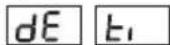

By using UP/DOWN buttons find "de ti" menu.
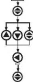
Press SET button (Most right digit of 5th display blinks)
By using UP/DOWN buttons, blinking digit value can be programmed.
By using SET button, switch respectively to the digits. Use BACK button go to go previous digit. After you entered last digit, press SET button, "de ti" is displayed in the display. (Data is entered but is not activated yet. For activating new data please follow the below steps.)
Press ESC button one by one until "SAU E SET yES" is displayed.
When "SAU E SET yES" is displayed, press SET button (When "SAU E SET yES" is displayed. If you press ESC button or choose "no" option instead of "yES" option, new data will be cancelled and previous value will be activated).
Reset Menu (hL, dE, E-1, E-2, C-1, C-2, rUn hoUr, SP hoU r):

In this menu value of min., max., max. demand, energy values, pulse counters, run hour and alarm clock are erased. It saves the instant measured min., max., max. demand energy values, the devices running time, time after the device is set into its memory. In this menu when you enter "rES Et hL/dE/E-1/E-2/C-1/C-2/rUn hoUr/SP hoU r" menu then press "yES" parameter, then quit from all menus if you confirm the changes all the values are erased at the same time. Note: Measured values which are saved in memory are not affected from power cut.
Reset Menu (hL, dE, E-1, E-2, C-1, C-2, rUn hoUr, SP hoU r):
Press SET button for 3 sec. (trA Fo menu is displayed.)

By using UP/DOWN buttons find "rES Et" menu.
Press SET button (rES Et hL menu is displayed.)

By using UP/DOWN buttons "rES Et hL/dE/E-1/E-2/C-1/C-2/rUn hoU r/SP hoU r" menu.

Press SET button (rES Et hL/dE/E-1/E-2/C-1/C-2/rUn hoU r/SP hoU r is displayed).

By using UP/DOWN buttons, if you want to delete, the min., max., max. demand, energy values, the running time of the device and the running time after the device is set; select "yES" otherwise select "no" option.
Press SET button, "rES Et hL/dE/E-1/E-2/C-1/C-2/rUn hoU r/SP hoU r" is displayed. (Data is entered but is not activated yet. For activating new data please follow the below steps)
Press ESC button one by one until "SAU E SET yES" is displayed.
When "SAU E SET yES" is displayed, press SET button (When "SAU E SET yES" is displayed. If you press ESC button or choose "no" option instead of "yES" option, new data will be cancelled and previous value will be activated).
NETWORK ANALYZER MPR-53CS
Pulse Menu
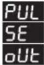
In this menu, 3 parameter can be selected. "PUL oUt rAt i0, PUL oUt o-1, PUL oUt o-2".
PUL oUt rAt 10 : In this menu, the pulse ratio of pulse outputs is defined. The values below can be defined.
1, 10, 100 (Wh/VArh); 1, 10, 100 (kWh/kVArh); 1 MWh/MVArh.
PUL oUt o-1 / PUL oUt o-2 : Pulse is taken for respected consumption which assigned in "PUL oUt rAt 10".
o-1/o-2 parameters can be set the below settings; ACI (Export/Import), A-I (Active Import), A-E (Active Export), rEA (Inductive / Capacitive), r-L (Reactive Inductive), r-C (Reactive Capacitive).
Press SET button for 3 sec. (trA Fo menu is displayed.)
By using UP/DOWN buttons, find "PUL SE oUt" menu.
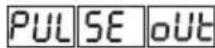
Press SET button "PUL oUt rAt 10" menu is displayed.
By using UP/DOWN buttons, find "PUL oUt rAt io/PUL oUt o-1 /PUL oUt o-2" menu.
Press SET button (1k / A-I / r-L blink)
By using UP/DOWN buttons, select required parameter of value.
Press SET button (Data is entered but is not activated yet. For activating the new data please follow the below steps.)
Press ESC button one by one until "SAU E SET yES" is displayed.
When "SAU E SET yES" is displayed, press SET button. If you press ESC button or choose "no" option instead of "yES" option by using UP/DOWN buttons, new data will be cancelled and previous value will be activated.

flowchart
graph TD
    A["Input"] --> B{Decision}
    B -->|Yes| C["Process 1"]
    B -->|No| D["Process 2"]
    C --> E{Decision}
    D --> F{Decision}
    E --> G["Output"]
    F --> G
    G --> H["Feedback to Process"]
    H --> I["End"]
Energy Counter (Eng Cnt) Menu:

MPR-53CS has 2 energy counters:
Energy Counter 1 (E-1), Energy Counter 2 (E-2).
"E-1 / E-2" have 4 parameters:
on : "E-1 / E-2" counters count without depending on any parameters.
I-1 : It counts when "E-1 / E-2" counter is "on" in digital input 1 (Activate E-1/E-2 counters, when digital input 1 is on).
I-2 : It counts when "E-1 / E-2" counter is "on" in digital input 2.
E-2: When "E-2" counter is active, "E-1" counter do not count. (It is only "E-1" counters parameter)
E-1: When "E-1" counter is active, "E-2" counter do not count. (It is only "E-2" counters parameter)
Note: When "E-2" is chosen in "E-1" counter and when "E-1" is chosen in "E-2" counter the counting status is undefined. When counters are set with this parameters, if digital inputs hasn't got the information "1" both of the counters count but if one or both of the counters has got the information, both of the counters don't count.
Press SET button for 3 sec. (trA Fo menu is displayed)
By using UP/DOWN buttons, find "Eng Cnt" menu.

Press SET button (Eng Cnt E-1 menu is displayed).
By using UP/DOWN buttons, find "Eng Cnt E-1" / "Eng Cnt E-2" menu.
Press SET button (on blinks)
By using UP/DOWN buttons, select required parameters.
Press SET button. (Data is entered, but is not activated yet. For activating the new data please follow the below steps)
Press ESC button one by one until "SAU E SET yES" is displayed.
When "SAU E SET yES" is displayed, press SET button. If you press ESC button or choose "no" option instead of "yES" option by using UP/DOWN buttons, new data will be cancelled and previous value will be activated.
User Password Setup :

In this menu user password is defined and activated. You must define and activate a 4 digit user password for preventing device setting from the illegal usage.
There are 2 sub menus under "Pin" menu.
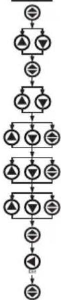
Changing of User Password :

This menu is to change the user password. Note: Factory default value for user password is "0000".
flowchart
graph TD
    A["Input"] --> B["Decision 1"]
    B --> C["Decision 2"]
    C --> D["Decision 3"]
    D --> E["Decision 4"]
    E --> F["Decision 5"]
    F --> G["Output"]
Press SET button for 3 sec. (trA Fo menu is displayed.)
By using UP/DOWN buttons, find "Pin" menu.
Press SET button (Pin ACt IUA tE menu is displayed.)
By using UP/DOWN buttons, find "Pin CHA n9E" menu is displayed.
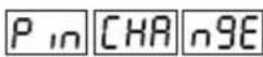
By using UP/DOWN/SET buttons, enter the old password.
By using UP/DOWN/SET buttons, enter the new password.
By using UP/DOWN/SET buttons, re-enter the new password.
Press SET button, "Pin CHA ngE" is displayed (Data is entered but is not activated yet. For activating the new data please follow the below steps).
Press ESC button one by one until "SAU E SET yES" is displayed.
When "SAU E SET yES" is displayed, press SET button. If you press ESC button or choose "no" option instead of "yES" option by using UP/DOWN buttons, new data will be cancelled and previous value will be activated.
Activating User Password :
This menu is used for activating the user password. After the user password is activated for entering to the menus; if the button is pressed for 3 sec., while the instant values are observed, user password is required. If the user password is entered wrong device does not latch.
Note: Factory default value of user password is "0000"
Press SET button for 3 sec. (trA Fo menu is displayed.)
By using UP/DOWN buttons, find "Pin" menu.
Press SET button
(Pin ACt IUA tE menu is displayed.)

Press SET button. First digit blinks.
By using UP/DOWN buttons enter the values for blinking digit. By using SET button, switch the other digits. Use BACK button to switch the previous digit. After setting the last digit, press the SET button, "Pin ACt of" is displayed. "on" can be selected by using UP/DOWN buttons. (Data is entered but is not activated yet. For activating the new data please follow the below steps.)
When latch function of set parameters is active, user can choose the way how to fault recovery in this menu. User can make this by 3 ways.
LAT Ch bUt ton: Removal of latch is chosen by pressing the "SET" button. By choosing "oFF", SET button becomes passive.
LAt Ch in PUt: Fault recovery can be done with using digital inputs. When "LAt Ch in I-1" is chosen only first digital input becomes active. When "LAt Ch in I-2" is chosen only second digital input becomes active.
When "LAt Ch in ALL" is chosen both of the digital inputs become active.
User can remove the latch when the signal comes to digital inputs. When "LAt Ch in oFF" is chosen this feature becomes passive.
LAt Ch AUto: When this feature is chosen fault recovery occurs at the end of the set time. User can set the turning time below.
User can choose the time between 15 min. - 180 min.. Time can be set by multiples 15 (15, 30, 45, 60, 75, 90, 105, 120, 135, 150, 165 or 180 min.).
NOTE: "LAt Ch bUt ton", "LAt Ch in PUt" ve "LAt Ch AUt o" can be activated at the same time.
Press SET button for 3 sec. (trA Fo menu is displayed.)
By using UP/DOWN buttons, find "LAt CH" menu.

Press SET button (LAt Ch bUt ton menu is displayed.)
By using UP/DOWN buttons, from the menus of "LAt Ch bUt ton/ in PUT/AUt o" choose the menu where the setting will be done.
Press SET button (on/off/off is displayed).
By using UP/DOWN buttons, select related parameter values ("on", "oFF"/"oFF", "I-1", "I-2", "ALL" / "oFF", "15 ... 180").
Press SET button, "LAT Ch bUt ton/in PUt/AUt o" is displayed. (Option is entered but is not activated yet. For activating the new data please follow the below steps.)
Press ESC button one by one until "SAU E SET yES" is displayed.
When "SAU E SET yES" is displayed, press SET button. If you press ESC button or choose "no" option instead of "yES" option by using UP/DOWN buttons, new data will be cancelled and previous value will be activated.
Pulse Counter (PUL SE CoU ntE r)
PUL C-1 ACt: In this menu, the activation of C-1 counter is done. If "on" is chosen C-1 counter will be active, and if "oFF" is chosen C-1 counter will become passive.
PUL C-1 rAt 10: In this menu first pulse counter is increased by 1. C-2 counters is set same way.
Example : If the ratio of the C-1 counters is 10, every 10 pulses come from In-1 input the counter counts 1.
Note: DC signal has to be given to the digital inputs when this menu is used. When AC signal is given, pulse counter counts according to the given sources frequency.
Note: If "ACt oFF" is chosen for C-1 and C-2 counters, the pulse counting feature will become passive. In instant values, passive counter is not displayed.
Press SET button for 3 sec. (trA Fo menu is displayed)
By using UP/DOWN buttons, find "PUL SE CoU ntE r"menu

Press SET button (PUL C-1 ACt menu is displayed).
By using UP/DOWN buttons, from the menus of "PUL C-1 ACt/C-1 rAt 10/C-2 ACt/C-2 rat 10" select the menu.
Press SET button (on/9999/on/9999 is displayed).
By using UP/DOWN buttons and select interested parameter values ("on-off"/"0001...9999"/"on-off"/"0001...9999").
Press SET button, "PUL C-1 ACt/C-1 rAt 10/C-2 ACt/C-2 rat 10" is displayed. (Option is entered but is not activated yet. For activating the new data please follow the below steps.)
Press ESC button one by one, until "SAU E SET yES" is displayed.
When "SAU E SET yES" is displayed, press SET button. If you press ESC button or choose "no" option instead of "yES" option by using UP/DOWN buttons, new data will be cancelled and previous value will be activated.

Hour menu:
In this menu run hour and setpoint hour is set.
"hoU r ACT": In this menu the run hours activation conditions are set. When "hoU r ACT on" is chosen, the run hour keeps working unconditionally.
When "hoU r ACT i-1" is chosen, the run hour runs if first digital input is active.
When "hoU r ACT 1-2" is chosen, the run hour runs if second digital input is active.
When "hoU r ACT ALL" is chosen, the run hour runs if one of the digital inputs is active.
"hoU r SP": In this menu, alarm time is set. When the set time reaches "SP -h" chosen output will be active.
Between 0001 - 9999 the hours can be set.
"hoU r oUt": In this menu the alarm output is chosen. It can be chosen between 1 ... 8. First and second outputs are relay outputs 3. ... 8 outputs are digital outputs.
Press SET button for 3 sec. (trA Fo menu is displayed)
By using UP/DOWN buttons find "hoU r" menu
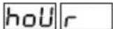
Press SET button ("hoU r SP" menu is displayed.)
Press SET button ("hoU r SP 000 0" is displayed)
By using UP/DOWN buttons, enter the values for blinking digits. By using SET button, other digits in turn, by using BACK button for previous menu. When last digit is programmed press SET button, "hoU r SP" is displayed.
By using UP/DOWN buttons from the menus of "hoU r ACT/oUt" select the menu.
Press SET button (on/1 displayed).
By using UP/DOWN buttons set the related parameters values ("on", "i-1", "i-2", "ALL" / "1 ... 8").
Press SET button, "hoU r ACT/oUt" is displayed (Option is entered but is not activated yet. or activating please follow the below steps).
Press ESC button one by one until "SAU E SET yES" is displayed.
When "SAU E SET yES" is displayed, press SET button. If you press ESC button or choose "no" option instead of "yES" option by using UP/DOWN buttons, new data will be cancelled and previous value will be activated.
Setpoint menu:
In this menu setpoint setting can be programmed. In this menu there are 16 setpoint setting (SP -01 ... SP -16). "SP -xx ACT" menu must be activated from the chosen setpoint menu. If not, user can not enter the "SP -xx" parameters.
"SP -01 ... SP -16": 16 setpoint settings which are set by the user. "SP-01" protection setting activation and settings of the sub menu parameters are given below. All other setpoint protection settings can be done by same way.
"SP -01 ACt": In this menu "SP -01" protection settings is done. When protection setting is chosen "oFF", SP -01's other menus can not be reached.
"SP -01 ACt on": Protection setting is active.
"SP -01 ACT oFF": Protection setting is passive.
"SP -01 PAr": In this menu 76 different parameter's settings is done. Only one of these parameters can be setted.
Note : Protection settings parameters and the information are in the attachment.
"SP -01 oPE": In this menu, extreme, low or both protection settings are determined. Sub menus are explained below.
"SP -01 oPE rAn qE": Low, extreme protection is done.
"SP -01 oPE hig hEr": Extreme protection is done.
"SP -01 oPE LoU Er": Low protection is done.
"SP -01 hi": In this menu extreme protection value is set.
"SP -01 Lo": In this menu low protection value is set.
Note: When extreme protection value is chosen low protection
value is closed, and when low protection value is chosen extreme protection value is closed in "SP -01 oPE" menu.
"SP -01 hYS": In this menu fault recovery hysteresis value is set.
"SP -01 ond": In this menu entering the fault delay is set (000.0-999.9 sec.).
"SP -01 oFd": In this menu fault recovery is set (000.0-999.9 sec.)
"SP -01 oUt": In this menu alarm output is chosen. 1. ... 8. outputs can be chosen. First and the second outputs are relay outputs, the others (3. ... 8) are digital outputs.
"SP -01 LAt Ch": In this menu lock function is activated.
"SP -01 LAt oFF": Closes the latch function
"SP -01 LAt on": Activates the latch function.
Note: Latch functions are set in latch menu.
Note: When protection parameters give error the user can see the erroneous parameter by using UP/DOWN buttons in instant values (more than one error use SET button).

flowchart
graph TD
    A["+"] --> B["△"]
    B --> C["▽"]
    C --> D["÷"]
    D --> E["△"]
    E --> F["▽"]
    F --> G["÷"]
    G --> H["△"]
    H --> I["▽"]
    I --> J["÷"]
    J --> K["△"]
    K --> L["▽"]
    L --> M["÷"]
    M --> N["△"]
    N --> O["▽"]
    O --> P["÷"]
    P --> Q["△"]
    Q --> R["▽"]
    R --> S["÷"]
    S --> T["△"]
    T --> U["▽"]
    U --> V["÷"]
    V --> W["△"]
    W --> X["▽"]
    X --> Y["÷"]
    Y --> Z["△"]
    Z --> AA["▽"]
    AA --> AB["÷"]

flowchart
graph TD
    A["Input"] --> B{Decision}
    B -->|Yes| C["Process 1"]
    B -->|No| D["Process 2"]
    C --> E{Decision}
    D --> F{Decision}
    E --> G["Output"]
    F --> G
    G --> H["End"]
NETWORK ANALYZER MPR-53CS

flowchart
graph TD
    A["Start"] --> B{Decision 1}
    B -->|Yes| C["Process 1"]
    B -->|No| D["Process 2"]
    C --> E{Decision 2}
    D --> F{Decision 3}
    E --> G["Output 1"]
    F --> H["Output 2"]
    G --> I["Final Step"]
    H --> I
    I --> J["End"]
Press SETbutton for 3 sec. (trA Fo menu is displayed.)
By using UP/DOWN buttons find "SEt Poi nt" menu.

Press SET button ("SP -01" menu is displayed)
By using UP/DOWN buttons select one of the setpoint settings "SP -01 .. SP -16" (In example SP -01 is chosen)
Press SET button ("SP -01 ACt" is displayed)
Press SET button ("SP -01 ACt off" is displayed). By using UP/DOWN buttons, select "SP -01 ACt on" and press SET button (SP -01 ACt is displayed).
Note: If you select "SP -01 ACt oFF", parameter settings can not be done for "SP -01".
By using UP/DOWN buttons select protection parameter from "SP -01 Par" menu. (for example "SP -01 PAr 3-P L-n" setting is selected).
Press SET button ("SP 0-1 PAr" is displayed).
By using UP/DOWN buttons find "SP -01 oPE" menu. Press SET button ("SP -01 oPE rAn gE" in displayed). By using UP/DOWN buttons select "SP -01 oPE rAn gE/hig hEr/LoU Er" protection form (for example "SP -01 oPE rAn gE" is selected).
Press SET button, "SP -01 oPE" is displayed.
By using UP/DOWN buttons from the menus of "SP -01 Hi/Lo/hYS /ond/oFd/oUt/Lat Ch" select the menu.
Press SET button, "SP -01 hi 0 00.0 / Lo 0 00.0 / hYS 0 00.0 / ond 0 00.0 / oFd 0 00.0 / oUt 1 / LAt oFF" is displayed.
By using UP/DOWN buttons select related parameter values (000.0-300.0/000.0-300.0/000.0-150.0/000.0-999.9/000.0-999.9/1-8/on-oFF).
Press SET button "SP -01 Hi/Lo/hYS/ond/oFd/oUt/Lat Ch" is displayed. (Option is entered but is not activated yet. For activating please follow the below steps)
Press ESC button one by one, until "SAU E SET yES" is displayed.
Press SET button when "SAU E SET yES" is displayed. If you press ESC button or choose "no" option instead of "yES" option by using UP/DOWN buttons, new data will be cancelled and previous value will be activated.
Serial Communication
The device has optical isolated MODBUS RTU communication protocol. All the measured parameters can be transferred to the computer. Transformer ratio and communication parameters can be set. Saved demand and energy values can be resetted.
Parameter Settings
Address Parameter : Between 001-247.
Baud Rate parameter : Can be chosen 2400, 4800, 9600, 19200 and 38400 bps. Parity parameter : Can be chosen "no", "odd" and "EUEn".
Press SET button for 3 sec. (trA Fo menu is displayed.)
By using UP/DOWN buttons find RS-485 menu
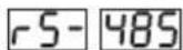
Press SET button (rS- 485 Adr ES menu is displayed)
By using UP/DOWN buttons from the menus of "rS-485 Adr ES/bAU d/PAr ity" select the menu.
Press SET button (001 / 9600 /no is displayed)
By using UP/DOWN buttons select related parameter values (001...247 / 2400...38400 /no, EUEn, odd).
Press SET button, "rS-485 Adr ES/bAU d/PAr ity" is displayed. (Option is entered but is not activated yet. For activating please follow the below steps)
Press ESC button one by one, until "SAU E SEt yES" is displayed.
Press SET button when "SAU E SEt yES" is displayed. If you press ESC button or choose "no" option instead of "yES" option by using UP/DOWN buttons, new option will be cancelled, previous option will be activated.
MODBUS RTU PROTOCOL
Standart MODBUS RTU message is shown below.
| T | ADDRESS8 BIT | FUNCTION8 BIT | DATA NX8BIT | CRCH | CRCL | T |
The T times corresponds to a time in which data must not be exchanged on the communication bus to allow the connected devices to recognize the end of one message and the beginning of another. This time must be at least 3.5 characters at the selected baud rate. Adress range (1-247) is address of the connected device. The data field contains data sent to the slave by master or data sent to master by slave. CRC is a error check method by using MODBUS RTU protocol and consists of 2 bytes.
Available Modbus Function
| 03H | READ HOLD REGISTERS |
| 06H | PRESET SINGLE REGISTER |
| 10H | PRESET MULTIPLE REGISTERS |
Read Hold (03) function is used for reading the measured parameter and setting values. Device will sent error message if the device tries to read addresses which are not in the register table.
For example to read phase 1 voltage below message can be sent; 01 03 00 00 00 02 XX XX
01 Device address
03 Function
00 MSB address
00 LSB address
00 Register number MSB
02 Register number LSB
XX CRC MSB
XX CRC | SB
Preset Single Register (06) function is used for writing energy values, erasing energy counter or resetting the min., max. demand values. Current transformer ratio can be set between 1-2000, voltage transformer ratio can be set between 1-400000.
For example setting CT ratio as 100; 01 06 80 02 00 64 XX XX
01 Device address
06 Function
80 MSB address
02 LSB address
00 Data MSB
64 Data LSB
XX CRC MSB
XX CRC USB
Preset Multiple register (10H) function is used for changing more than one register value.
For example setting ratio as 100 and voltage transformer ratio as 20.0.; 01 10 80 00 00 02 04 00 C8 00 64 XX XX girilebilir.
01 Device Address
10 Function
80 MSB address
00 LSB address
00 Register number MSB
02 Register number LSB
04 Byte count
00 Data MSB
C8 Data LSB
00 Data MSB
64 Data LSB
XX CRC MSB
XX CRC LSB
Digital Input
In1 (input 1) if 12-48 V AC / DC is applied to in 1, 0 bit of DIN register is set as "1". In otherwise 0 bit of DIN register is set as "0".
In2 (input 2) if 12-48 V AC / DC is applied to in 2, 1 bit of DIN register is set as "1". In otherwise 0 bit of DIN register is set as "0".
Parameters are sent in 32 bit Hexadecimal form. For example 230,0 V voltage is sent as 000008FCH. Cosj is divided by 1000. 0.980 Cosj value is sent as 000003D4H. Energy values are sent as 64bit.
12345678901234567890 Wh = AB 54 A9 8C EB 1F 0A D2 Wh
Data Cable :
- 24 AWG or thicker
- Less than 100 ohm-km impedance
- Nominal characteristic impedance in 100 kHz is 100 ohm.
- Between 2 wires mutual capacitance is less than 60 pF/m
- Between one wire and all the wires which are grounded mutual capacitance is less than 120 pF/m.
- Double wire.
ERROR CODES
Slave device (MPR-53CS) sends error message when receive any missing query. Error codes are given below:
01 Invalid Function: If any message except given above is used, then 01 error messages will be sent.
02 Invalid Register: Error 02 will be send when a reading of a register is requested, except the registers which mentioned in table.
03 Invalid data: If any different value is been set for dedicated Transformer values and nonzero for demand value, then error message 03 will be sent.
NETWORK ANALYZER MPR-53CS
31 DEVICES CAN BE CONNECTED AT THE SAME LINE

flowchart
graph LR
    A["TR B A GND"] --> B["MPR-53CS-31"]
    C["TR B A GND"] --> D["MPR-53CS-2"]
    E["TR B A GND"] --> F["MPR-53CS-1"]
    B --> G["RS485/RS232 CONVERTER"]
    D --> G
    F --> G
    G --> H["PC"]
    style A fill:#f9f,stroke:#333
    style C fill:#f9f,stroke:#333
    style E fill:#f9f,stroke:#333
    style G fill:#ccf,stroke:#333
    note right of A "MAX. 1200 mt."
    note right of G "B A GND"
    note right of H "PC"
MAX. 247 DEVICES CAN BE CONNECTED AT SAME LINE BY USING REPEATER.

flowchart
graph LR
    A["TRB AGND"] --> B["MPR-53CS-247"]
    B --> C["REPEATER"]
    C --> D["MPR-53CS-31"]
    D --> E["MPR-53CS-2"]
    E --> F["MPR-53CS-1"]
    F --> G["RS485/RS232 CONVERTER"]
    G --> H["PC"]
    style A fill:#f9f,stroke:#333
    style H fill:#ccf,stroke:#333
    note1["MAX. 1200 mt."]
    note2["MAX. 1200 mt."]
    note3["B GND"]
    note4["PC"]
    note5["MPR-53CS-247"]
    note6["MPR-53CS-31"]
    note7["MPR-53CS-2"]
    note8["MPR-53CS-1"]
PK 26 Box Connection Diagram
3 Phase neutral
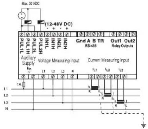
3 Phase without neutral

Note: For CT-25 models:
k: When CT-25 is used, Red cable is connected to k terminal.
I: When CT-25 is used, Black cable is connected to I terminal.

3 Phase without neutral current input with Aron wiring configuration

3 Phase without neutral current input with Aron wiring configuration
NETWORK ANALYZER MPR-53CS
PR 19 Box Connection Diagram

3 Phase neutral

3 Phase without neutral

I: When CT-25 is used, Black cable is connected to I terminal.
3 Phase without neutral current input w ^th

Aron wiring configuration
3 Phase without neutral current input with
Aron wiring configuration
NETWORK ANALYZER MPR-53CS
Technical Data
Operating Voltage (Un) : Please look behind the device.
Operating Frequency (f) : 45-65 Hz
Auxiliary supply Power Consumption : < 4 VA
Measuring Input Power Consumption : < 1 VA
VIn : 10-300 V AC 45-65 Hz. (L-N)
: 10-500 V AC 45-65 Hz. (L-L)
In : 0.05 - 5.5 A\~
1-120 A\~ (for CT-25)
Measuring Range : 10V...200 kV AC
0...215 M (W.VAr.VA)
: 99999999999.9 kWh, kVArh
Class : 1% ± 1 digit [(10%-110%) xFull Scale]
Voltage Transformer ratio (Vtr) : 0,1 ... 4000,0
Current Transformer Ratio (Ctr) : 1 ... 2000
Max. Ctr x Vtr : 40.000
Hour SP : 1-9999 hour (programmable)
Demand Time : 1-60 min. (programmable)
Serial Interface
Optically Isolated, programmable
Baud Rate
Address : 1-247
Parity
Relay Output
Pulse Output
Switch Period
80 msec. pulse width
Operating Current
Operating Voltage
Input : 12...48 V AC / DC
Ambient Temperature : -5°C; +50°C
Display
Dimensions
Equipment Protection Class
Box Protection Class
Box Material
Installation
Rail Mounted (PK-26)
Wire Crossection For Terminal Block
Weight
Installation Class
Panel Size
46x107 mm (PK-26)
Factory Settings
Transformer :
Ctr(Current Transformer Ratio):0001
trn (Turn number for CT-25): 01
Utr (Voltage Transformer Ratio) : 0001.0
CAL (Calculation Method) : 1
Pin:0000 (Not Activated)
RS-485:
Adr (Address) : 1
: No, Odd, Even, 8 Data Bits, 2 Stop Bits
: 2 NO, 5 A, 1250 VA
: NPN Transistör
: Min. 100 msec. pulse period
: Max. 50 mA
: 5.....24 V DC, max. 30 VDC
: Red LED Display
: PR-19, PK-26
: Double Installation-Class II (☐)
: IP 40 (front panel)
: Non-flammable
: Panel Mounted (PR-19)
: 2.5 mm²
: 0.45 kg (PR-19, PK-26)
: Class III
: 91x91 mm (PR-19)
Eng Cnt :
E-1 (Energy Counter 1) : on
E-2 (Energy Counter 2) : on
PULSE :
rAt (Ratio) : 1k
o-1 (Output 1): A-I
o-2 (Output 2): r-L
dEti (Delay Time) : 15
hoU r :
hoU r SP (Setpoint) : 0000
ACt : on
out:1
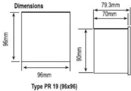

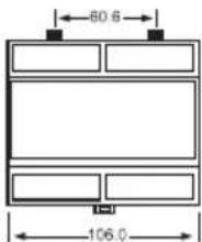
Type PK 26
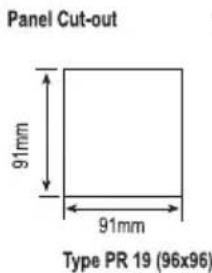

PULSE Cnt :
C-1 ACt (Pals Counter 1) : on
C-2 ACt (Pals Counter 2) : on
C-1 rAt io (Ratio) : 0001
C-2 rAt io (Ratio) : 0001
LAT Ch :
bUt ton : on
in PUT : oFF
AUT o : oFF
Set point :
SP -01....-16 ACt : oFF
PRECAUTIONS FOR INSTALLATION AND SAFE USE

In CT-25 (120A) compliant models, only CT-25 current transformer must be used. Other type of CT's have a high risk to damage to device.
Failure to follow those instructions will result in death or serious injury.
- Disconnect all power before working on equipment.
- When the device is connected to the network, do not remove the front panel.
- Do not try to clean the device with solvent or the like. Only clean with dry cloth.
- Verify correct terminal connections when wiring.
- Electrical equipment should be serviced only by your component seller.
- Only for rack panel mounting.
- The type of circuit breaker must be F and current limit value must be 1A
- No responsibility is taken on by manufacturer or any its subsidiaries for any conditions about the wrong using of this device

No responsibility is assured by the manufacturer or any of its subsidiaries for any consequences arising out of the use of this material.
NETZANALYSATOR MPR-53CS
General
Run Hours: Shows MPR-53CS's running hour. This can be resetted and can be controlled by digital inputs different from Total Hour. When selected the control with digital inputs, it runs if there is a signal in digital inputs. It does not run if there is no signal in digital inputs.
: 0...215 M (W, VAr, VA)
: 99999999999.9 kWh, kVArh
Klasse
: 1% ± 1 Ziffer [(10%-110%) x volle Skala]

Typ PK 26
Call Center Technical Support: 0850 888 84 25
- Functions of Buttons
- Use of MPR-53CS:
- Digital Inputs
- Energy Pulse Outputs
- Pulse Counter
- Digital Outputs
- Relay Outputs
- Total Hours
- Run Hours
- Setpoint Hours
- Monitoring of Min.- Max. and Max. Demand Values:
- Monitoring THD Values
- Monitoring Neutral Current
- Monitoring Setpoint Parameters Fault Warning
- Calculation Methods for Active / Reactive Values
- Note :
- NETWORK ANALYZER MPR-53CS
- Current Transformer Ratio Setup:
- Entering Turn Number:
- transformer Ratio Setup:
- Chosing connection option:
- Energy Calculation Method Settings:
- Max. Demand Time Setup:
- Reset Menu (hL, dE, E-1, E-2, C-1, C-2, rUn hoUr, SP hoU r):
- Pulse Menu
- Energy Counter (Eng Cnt) Menu:
- User Password Setup :
- Changing of User Password :
- Activating User Password :
- Pulse Counter (PUL SE CoU ntE r)
- Hour menu:
- Setpoint menu:
- Serial Communication
- Parameter Settings
- MODBUS RTU PROTOCOL
- Digital Input
- Data Cable :
- ERROR CODES
- Technical Data
- Factory Settings
- Transformer :
- RS-485:
- Eng Cnt :
- PULSE :
- hoU r :
- PULSE Cnt :
- LAT Ch :
- Set point :
- PRECAUTIONS FOR INSTALLATION AND SAFE USE
- NETZANALYSATOR MPR-53CS
- General
Brand : ENTES
Model : MPR-53CS-DIN
Category : Analyseur de réseau