
Cine 50 - Tripod Sachtler - Free user manual and instructions
Find the device manual for free Cine 50 Sachtler in PDF.


| Product Type | Fluid Head for Tripod |
| Payload | 10 - 50 kg (22 - 110 lbs) |
| Counterbalance Steps | 18 |
| Drag Grades | 9 each horizontal and vertical, plus zero setting |
| Tilt Angle | +90° / -60° |
| Sliding Range | 150 mm (5.9 in) |
| Weight | 10.1 kg (22.3 lbs) |
| Panning Range | 360° |
| Temperature Range | -40°C (-40°F) to 60°C (140°F) |
| Camera Fitting | Sideload |
| Tripod / Pedestal Fitting | 150 mm bowl |
| Pan Bar | One telescopic pan bar, length 430 - 600 mm (16.9 - 23.6 in) |
| Batteries | 3 each 625 U or LR9 button cells |
| Illumination | Touch bubble, self-illuminating up to 45 seconds |
| Brakes | Vibrationless horizontal and vertical brakes |
| Safety Features | Tilt safety lock, red safety lock on sideload |
| Drag Setting | Nine levels plus zero, indexed positions |
| Maintenance | Turn drag rings from 0 to maximum before and after use |
| Warranty | Extended warranty upon registration at www.sachtler.com |
Frequently Asked Questions - Cine 50 Sachtler
User questions about Cine 50 Sachtler
0 question about this device. Answer the ones you know or ask your own.
Ask a new question about this device
Download the instructions for your Tripod in PDF format for free! Find your manual Cine 50 - Sachtler and take your electronic device back in hand. On this page are published all the documents necessary for the use of your device. Cine 50 by Sachtler.
USER MANUAL Cine 50 Sachtler
Publication date 02/02/24

Copyright
Copyright © 2024
All rights reserved.
Original Instructions: English
All rights reserved throughout the world. No part of this publication may be stored in a retrieval system, transmitted, copied or reproduced in any way, including, but not limited to, photocopy, photograph, magnetic or other record without the prior agreement and permission in writing of Videndum Plc.
Disclaimer
The information contained in this publication is believed to be correct at the time of printing. Videndum Ltd reserves the right to make changes to the information or specifications without obligation to notify any person of such revision or changes. Changes will be incorporated in new versions of the publication. We are making every effort to ensure that our publications are updated on a regular basis to reflect changes to product specifications and features. Should this publication not contain information on the core functionality of your product, please let us know. You may be able to access the latest revision of this publication from our website. Videndum Production Solutions Ltd reserves the right to make changes to product design and functionality without notification.
Trademarks
All product trademarks and registered trademarks are the property of Videndum Plc.
All other trademarks and registered trademarks are the property of their respective companies.
Published by:
Videndum Production Solutions Ltd
Email: publications@videndum.com
Table of Contents
1 Safety 4
General Safety 4
General 5
2 Operating Elements 6
3 Operation 8
3.1 Levelling of the fluid head 8
3.2 Removing of the camera plate 8
3.3 Mounting of the camera 8
3.4 Removing of the camera 8
3.5 Positioning of the camera 9
3.6 Adjusting the camera's counterbalance 9
3.7 Setting of the Drag 9
3.8 Brakes 9
3.9 Support for view finder extension and Front Box 9
3.10 Change of the batteries 9
3.11 Transport setting for drag, counterbalance and brakes 10
4 Technical Specification 11
4.1 General data 11
4.2 Dimensions ...... 11
6 Warranty 12
UK Declaration of Conformity 22
EU Declaration of Conformity 22
FCC Compliance Statement 22
Environmental considerations 23
General Safety
Important information on the safe installation and operation of this product. Read this information before operating the product. For your personal safety, read these instructions.
Do not operate the product if you do not understand how to use it safely.
Save these instructions for future reference.
Warning Symbols Used in these Instructions
Safety cautions are included in these instructions. These safety instructions must be followed to avoid possible personal injury and avoid possible damage to the product.
⚠ Warning! Where there is a risk of personal injury or injury to others, comments appear supported by the word 'WARNING'.
Caution! Where there is a risk of damage to the product, associated equipment, process or surroundings, comments appear supported by the word 'CAUTION'.
Refer to the product instruction manual.
Warning! Pinch point, injury to fingers or hands, exercise caution.
Health and Safety
Risk of personal injury or injury to others. All personnel must be fully trained and adhere to correct manual handling techniques and Health & Safety regulations. It is the responsibility of the local organisation to enforce safe working practices at all times.
Mounting and Installation
⚠ Warning! Do not fit a head to a tripod that cannot support the combined mass of the head and its full payload.
Warning! Do not place fingers between the platform and the body of the fluid head.
Caution! Always lock the horizontal and vertical brakes when the camera is mounted but not in use or when leveling the fluid head on the tripod.
Caution! Hold the camera securely when mounting or dismounting from the fluid head and when making adjustments to the tripod height or footprint.
Caution! Always hold the pan bar when making adjustments to the counterbalance or camera position. Do not use the pan bar to lift or move the tripod and fluid head.
Caution! Do not attach heavy items to the pan bar.
⚠ Caution! Always remove the camera before transporting.
Maintenance
⚠ Warning! The fitting of non-approved parts and or accessories or servicing by non-approved personnel could effect the safety of the product. It may also invalidate the terms and conditions of the product warranty.
⚠ Caution! When replacing the battery, only use the same or an equivalent type of battery recommended for use with this product.
General
Caution! When releasing the vertical brake make sure that the camera is secured against any sudden movement.
Caution! Before releasing the vertical brake (at a non balanced camera set up) or the clamping of the camera/balance plate the camera must be secured against sudden movement, otherwise there may be a danger of finger trapping.
⚠ Caution! During camera tilt movements with extreme tilt angles there may be a danger of finger trapping between sideload plate and housing for users and third persons.
Caution! Before transport reset fluid drag to "0".


3.1 Levelling of the fluid head
Apply the vertical brake of the Cine 50 and hold the camera with one hand. Open the clamping screw of the fluid head and move the head in such a way, that the bubble moves into the level's black circle. Tighten the clamping screw firmly.
Touch Bubble
The Cine 50 has a self illuminating Touch bubble which allows easy levelling even under unfavourable lighting conditions.
The illumination is activated by strong tapping on the bubble. Depending on the force applied the bubble will glow up to 45 seconds.
3.2 Removing of the camera plate
The Cine 50 comes with a sideload camera plate clamp mechanism:
- Hold the camera plate with one hand.
- Press the red safety lock.
- Open the sideload lever (about 180° ) until the stop position.
- Press down the snap lock.
- Take out the camera plate.
3.3 Mounting of the camera
Attach the camera plate around the camera's centre of gravity.
- Turn the counterbalance knob to position 9
- Apply horizontal brake and release vertical brake.
- The springs of the counterbalance engage automatically by tilting the camera through the horizontal position (audible clicking).
- Lock the head with the tilt safety lock. The blocking and clicking into position of the tilt safety lock is achieved by pulling out the red knob and turning it 90° . Green marking on the red knob becomes invisible. Make sure that the tilt safety lock has engaged (the head can't be tilted any more).
- Place the camera plate in the dovetails guiding on the head.
- Lower the camera (plate). The snap lock will spring back and snap in to secure the camera plate when it is in a flat position
- Close the sideload lever until the red safety lock is locked (audible clicking).
Adjustment of the clamping force
There are a lot of camera plates from other brands (e.g. O'Connor, ARRI, ...) in the market. They principally fit to the Cine 50 but may have other manufacturing tolerances. If so, an adjustment of the clamping force is possible, by turning the allen screw clockwise to increase the force, counterclockwise to decrease clamping force.
3.4 Removing of the camera
- Lock the head with the tilt safety lock. The blocking and clicking into position of the tilt safety lock is achieved by pulling out the red knob and turning it 90°. Green marking on the red knob becomes invisible. Make sure that the tilt safety lock has engaged. (The head can't be tilted any more.)
- Hold the camera with one hand.
- Press the red safety lock.
- Open the sideload lever until the stop position (about 180°).
- Press down the snap lock.
- Take out the camera.
3.5 Positioning of the camera
- Hold the camera by securing the pan bar.
- Apply the horizontal brake and release vertical brake and tilt safety lock by pulling out the red knob and turning it 90°. Green marking on the red knob becomes visible (rocking the pan bar up and down will facilitate this).
- Turn the counterbalance knob to position 1. Keep on holding the camera.
- Select 0 on the vertical drag adjustment ring.
- Press the red safety lock. Open the sideload lever approx. 90°.
- To balance the camera correctly, bring the c.o.g. of the camera right above the pivoting point of the fluid head. Compensate for a back heavy setup by sliding the camera plate forward and for a front heavy setup by sliding backwards.
- Lock the camera plate by closing the sideload lever until the red safety lock is locked.
⚠ Caution: If you cannot manage to center the camera, you should move the camera plate to a different position on the camera.
3.6 Adjusting the camera's counterbalance
- Hold the camera by securing the pan bar
- Release the vertical brake.
- Release the safety lock
- Turn the counterbalance knob to the counterbalance number which best compensates the weight of the camera.
- After each spring is engaged, check if the camera will remain in a tilted position without moving upwards or downwards significantly.
- With the half step switch you have the possibility to select intermediate steps, e.g. 1 ½, 2½, 3 ½ etc.
3.7 Setting of the Drag
The Cine 50 fluid head is equipped with nine drag levels horizontally and vertically and a zero setting. By turning the vertical setting and the horizontal setting the desired level of the fluid drag can be selected.
Turn the setting ring to "0" in order to switch off the drag completely.
If you set the setting rings on the same index number (e. g. "3") the degree of the horizontal and vertical drag is identical and this enables precise diagonal panning movements without jerks and vibrations. Make sure that you always turn the setting to the next indexed position. Engage the retainer pins by slowly panning or tilting the camera.
Panning or tilting the camera with settings between the indexed positions can damage the retainer pins and/or disks.
3.8 Brakes
The horizontal brake applies the lock for the pan and the vertical brake for the tilt movement. Both brakes are vibrationless and can be used during shooting.
3.9 Support for view finder extension and Front Box
The Cine 50 has on its left side a preparation to accept a support system for a view finder extension. At the front of the fluid head are drill holes to accept a Front Box bracket.
3.10 Change of the batteries
The illumination is powered by three standard type button cells (625 U or LR9) located in the battery holder, which can be opened with a sharp object such as a screwdriver.
Make sure to insert the new batteries according to the "plus" and "minus" symbols as indicated in the covering plate.
The batteries last for about 2000 illumination cycles.
3.11 Transport setting for drag, counterbalance and brakes
To ensure smooth operation of the setting rings for the drag over the long life time period of the fluid head, you should turn both setting rings from position "0" to maximum position, before and after the use of the fluid head. Setting during transportation:
- open both brakes - horizontal and vertical.
- Counterbalance and drag should be set to maximum position.
4.1 General data
Payload: 10 - 50 kg (22 - 110 lbs)
Counterbalance: 18 steps
Grades of drag: horizontally and vertically 9 each and 0
Tilt angle: +90° / -60°
Sliding range: 150 mm (5.9 in)
Weight: 10.1 kg (22.3 lbs)
Panning range: 360°
Temperature range: -40°C (-40°F) to 60°C (140°F)
Weight: 9.4 kg (20.7 lb)
Max. load: 50 kg (110.2 lb)
Camera fitting: Sideload
Tripod / Pedestal fitting: 150 mm bowl
Pan bar: one telescopic pan bar, length 430 - 600 mm (16.9 - 23.6 in)
Batteries: 3 each 625 U or LR9
4.2 Dimensions
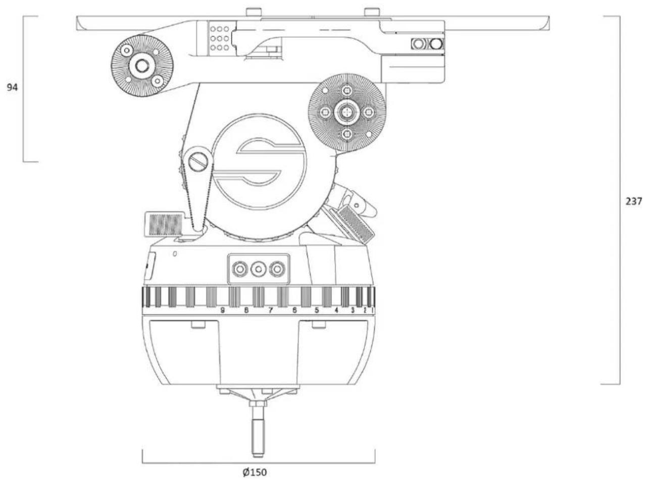
Warranty expires if:
- The fluid head was operated improperly or not in line with the specified technical data, or
- the head housing was opened by unauthorised personnel.
We reserve the right to make changes based on technical advances.
Please register at www.sachtler.com for an extended warranty period.
UK Declaration of Conformity
UK CA
Videndum Production Solutions Ltd. declares under our sole responsibility that the product detailed in this manual conforms with all relevant provisions of the following UK Regulations:
• The Electrical Equipment (Safety) Regulations 2016
- The Restriction of the Use of Certain Hazardous Substances in Electrical and Electronic Equipment Regulations 2012
A copy of the declaration is available on request.
UK contact: Videndum Production Solutions Ltd, William Vinten Building, Easlea Road, Bury St. Edmunds, IP32 7BY
EU Declaration of Conformity
CE
Videndum Production Solutions Ltd. declares under our sole responsibility, supported by Videndum Production Solutions GmbH - our authorized representative, that the product detailed in this manual conforms with all relevant provisions of the following EU directives:
• Restriction of Hazardous Substances Directive 2011/65/EU
• Electromagnetic Compatibility Directive 2014/30/EU
Low Voltage Directive 2014/35/EU Radio Equipment Directive 2014/53/EU
A copy of the declaration is available on request. EU contact: Videndum Production Solutions GmbH, Parkring 29, 85748 Garching, Germany
FCC Compliance Statement
FC
This device complies with Part 15 of the FCC Rules. Operation is subject to the following two conditions:
- This device may not cause harmful interference.
- This device must accept any interference received, including interference that may cause undesired operation.
Note: This equipment has been tested and found to comply with the limits for a Class B digital device, pursuant to Part 15 of the FCC Rules. These limits are designed to provide reasonable protection against harmful interference in a residential installation. This equipment generates, uses, and can radiate radio frequency energy and, if not installed and used in accordance with the instructions, may cause harmful interference to radio communications. However, there is no guarantee that interference will not occur in a particular installation. If this equipment does cause harmful interference to radio or television reception, which can be determined by turning the equipment off and on, the user is encouraged to try to correct the interference by one or more of the following measures:
- Reorient or relocate the receiving antenna.
- Increase the separation between the equipment and receiver.
- Connect the equipment into an outlet on a circuit different from that to which the receiver is connected.
- Consult the dealer or an experienced radio/television technician for help.
Modifications not expressly approved by the manufacturer could void the user's authority to operate the equipment under FCC rules.
Environmental considerations
European Union Waste of Electrical and Electronic Equipment (WEEE) Directive (2012/19/EU)

This symbol marked on the product or its packaging indicates that this product must not be disposed of with general household waste. In some countries or European Community regions separate collection systems have been set up to handle the recycling of electrical and electronic waste products. By ensuring this product is disposed of correctly, you will help prevent potentially negative consequences for the environment and human health. The recycling of materials helps conserve natural resources. Visit our website for information on how to dispose of this product and its packaging.
In countries outside the EU:
Dispose of this product at a collection point for the recycling of electrical and electronic equipment according to your local government regulations
Disposal of waste batteries
Any batteries included with this product must not be treated as household waste. By ensuring these batteries are disposed of correctly, you will help prevent potentially negative consequences for the environment and human health, and help conserve natural resources.
Read “Changing the Battery” in this user guide for instructions on how to remove the battery from the product safely. Hand the battery over to the applicable collection point for recycling waste batteries.
Published by
Videndum Production Solutions Ltd.
Email: publications@videndum.com
Copyright 2024 - Videndum Production Solutions Ltd. All rights reserved
www.sachtler.com

Sachtler
A Videndum plc Brand

- COPYRIGHT
- DISCLAIMER
- TRADEMARKS
- PUBLISHED BY
- TABLE OF CONTENTS
- GENERAL SAFETY
- WARNING SYMBOLS USED IN THESE INSTRUCTIONS
- HEALTH AND SAFETY
- MOUNTING AND INSTALLATION
- MAINTENANCE
- GENERAL
- 3.1 LEVELLING OF THE FLUID HEAD
- TOUCH BUBBLE
- 3.2 REMOVING OF THE CAMERA PLATE
- 3.3 MOUNTING OF THE CAMERA
- 3.4 REMOVING OF THE CAMERA
- 3.5 POSITIONING OF THE CAMERA
- 3.6 ADJUSTING THE CAMERA'S COUNTERBALANCE
- 3.7 SETTING OF THE DRAG
- 3.8 BRAKES
- 3.9 SUPPORT FOR VIEW FINDER EXTENSION AND FRONT BOX
- 3.10 CHANGE OF THE BATTERIES
- 3.11 TRANSPORT SETTING FOR DRAG, COUNTERBALANCE AND BRAKES
- 4.1 GENERAL DATA
- UK DECLARATION OF CONFORMITY
- UK CA
- EU DECLARATION OF CONFORMITY
- CE
- FCC COMPLIANCE STATEMENT
- FC
- ENVIRONMENTAL CONSIDERATIONS
- IN COUNTRIES OUTSIDE THE EU
- DISPOSAL OF WASTE BATTERIES
Brand : Sachtler
Model : Cine 50
Category : Tripod