DP813A - Measurement Rigol - Free user manual and instructions
Find the device manual for free DP813A Rigol in PDF.


| Product Type | Programmable DC Power Supply |
| Model | DP813A |
| Brand | Rigol |
| Number of Outputs | 1 |
| Output Voltage Range | 0 V to 30 V |
| Output Current Range | 0 A to 1 A |
| Max Output Power | 30 W |
| Display | 4.3-inch TFT LCD |
| Interfaces | USB Host, USB Device, LAN, RS232, Digital I/O |
| Output Setting Resolution | 1 mV / 0.1 mA |
| Output Measurement Resolution | 0.1 mV / 0.01 mA |
| Ripple & Noise | ≤ 1 mVrms / ≤ 2 mArms |
| Load Regulation | ≤ 0.01% + 2 mV (Voltage) / ≤ 0.01% + 250 µA (Current) |
| Line Regulation | ≤ 0.01% + 2 mV (Voltage) / ≤ 0.01% + 250 µA (Current) |
| Dimensions (W x H x D) | 235 mm x 110 mm x 365 mm |
| Weight | Approximately 4.5 kg |
| Input Power | 100 V - 240 V AC, 50/60 Hz, 100 VA max |
| Cooling | Fan cooling, intelligent speed control |
| Safety Compliance | CE, UL, CSA, EN 61010-1 |
| Accessories Included | Power cord, user manual, test report, USB cable |
| Warranty | 3 years |
Frequently Asked Questions - DP813A Rigol
User questions about DP813A Rigol
0 question about this device. Answer the ones you know or ask your own.
Ask a new question about this device
Download the instructions for your Measurement in PDF format for free! Find your manual DP813A - Rigol and take your electronic device back in hand. On this page are published all the documents necessary for the use of your device. DP813A by Rigol.
USER MANUAL DP813A Rigol
DP800 Series Programmable Linear DC Power Supply
Jun. 2021
RIGOL TECHNOLOGIES CO., LTD.
Guaranty and Declaration
Copyright
© 2021 RIGOL TECHNOLOGIES CO., LTD. All Rights Reserved.
Trademark Information
RIGOL ^® is the trademark of RIGOL TECHNOLOGIES CO., LTD.
Publication Number
PGH03109-1110
Software Version
00.01.17
Software upgrade might change or add product features. Please acquire the latest version of the manual from RIGOL website or contact RIGOL to upgrade the software.
Notices
● RIGOL products are covered by P.R.C. and foreign patents, issued and pending.
- RIGOL reserves the right to modify or change parts of or all the specifications and pricing policies at the company's sole decision.
● Information in this publication replaces all previously released materials.
● Information in this publication is subject to change without notice.
- RIGOL shall not be liable for either incidental or consequential losses in connection with the furnishing, use, or performance of this manual, as well as any information contained.
- Any part of this document is forbidden to be copied, photocopied, or rearranged without prior written approval of RIGOL.
Product Certification
RIGOL guarantees that this product conforms to the national and industrial standards in China as well as the ISO9001:2015 standard and the ISO14001:2015 standard. Other international standard conformance certifications are in progress.
Contact Us
If you have any problem or requirement when using our products or this manual, please contact RIGOL.
E-mail: service@rigol.com
Website: www.rigol.com
Document Overview
This manual introduces how to program the power supply over remote interfaces in details.
Main Topics in this Manual:
Chapter 1 Programming Overview
This chapter introduces how to build the remote communication between the power supply and PC and how to control the power supply remotely. Besides, it also provides a brief introduction of the syntax, symbols, parameter types and abbreviation rules of the SCPI commands as well as the SCPI status system.
Chapter 2 Command System
This chapter introduces the syntax, function, parameters and using instruction of each DP800 command in A-Z order.
Chapter 3 Application Examples
This chapter provides the application examples of the main functions of the power supply. In the application example, a series of commands are combined to realize the corresponding basic function of the power supply.
Chapter 4 Programming Demos
This chapter introduces how to program and control DP800 using various development tools, such as Visual C++, Visual Basic and LabVIEW.
Chapter 5 Appendix
This chapter provides various information, such as the command list and factory setting list.
Tip
For the newest version of this manual, please download it from RIGOL official website (www.rigol.com).
Format Conventions in this Manual:
1 Key
The function key on the front panel is denoted by the format of "Key Name (Bold) + Text Box" in the manual. For example, Utility denotes the "Utility" key.
2 Menu
The menu item is denoted by the format of "Menu Word (Bold) + Character Shading" in the manual. For example, SysInfo denotes the "SysInfo" item under Utility.
3 Operation Step
The next step of the operation is denoted by an arrow "→" in the manual. For example, Utility → System denotes that first press Utility on the front panel and then press System.
Content Conventions in this Manual:
DP800 series programmable linear DC power supply includes the following models. Unless otherwise noted, in this manual, DP831A is taken as an example to illustrate the using method of each DP800 series command.
| Model | Number of Channels | Output Voltage/Current |
| DP832A/DP832 | 3 | 30V/3A, 30V/3A, 5V/3A |
| DP831A/DP831 | 3 | 8V/5A, 30V/2A, -30V/2A |
| DP822A/DP822 | 2 | 20V/5A, 5V/16A |
| DP821A/DP821 | 2 | 60V/1A, 8V/10A |
| DP813A/DP813 | 1 | 8V/20A (Range 1), 20V/10A (Range 2) |
| DP811A/DP811 | 1 | 20V/10A (Range 1), 40V/5A (Range 2) |
Contents
Guaranty and Declaration.... I
Document Overview ......II
Chapter 1 Programming Overview ......1-1
To Build Remote Communication....1-2
Remote Control Methods 1-3
SCPI Command Overview 1-3
Syntax 1-3
Symbol Description....1-4
Parameter Type 1-4
Command Abbreviation....1-5
SCPI Status Registers....1-5
Questionable Status Register....1-9
Standard Event Register....1-12
Status Byte Register 1-13
Chapter 2 Command System 2-1
:ANALyzer Commands 2-2
:ANALyzer:ANALyze 2-2
:ANALyzer:CURRTime 2-3
:ANALyzer:ENDTime 2-4
:ANALyzer:FILE? 2-4
:ANALyzer:MEMORY 2-5
:ANALyzer:MMEMory....2-5
:ANALyzer:OBJECT....2-6
:ANALyzer:RESult?......2-6
:ANALyzer:STARTTime 2-7
:ANALyzer:VALue? 2-7
:APPLy Command....2-8
:APPLy 2-9
:DELAY Commands....2-11
:DELAY:CYCLEs 2-12
:DELAY:ENDState 2-13
:DELAY:GROUPs 2-14
:DELAY:PARAMeter 2-15
:DELAY[:STATE]....2-16
:DELAY:STATE:GEN 2-16
:DELAY:STOP....2-17
:DELAY:TIME:GEN 2-18
:DISPLAY Commands....2-19
:DISPLAY:MODE 2-19
:DISPLAY[:WINDow][:STATE] 2-20
:DISPLAY[:WINDow]:TEXT:CLEAR 2-20
:DISPLAY[:WINDow]:TEXT[:DATA] 2-21
IEEE488.2 Common Commands 2-22
*CLS 2-22
*ESE....2-23
*ESR? 2-24
*IDN? 2-24
*OPC 2-25
*OPT? 2-25
*PSC 2-26
*RCL 2-26
*RST 2-27
*SAV 2-27
*SRE 2-28
*STB? 2-28
*TRG 2-29
*TST? 2-29
*WAI....2-29
:INITiate Command 2-30
:INITiate 2-30
:INSTrument Commands 2-31
:INSTrument:COUPLE[:TRIGger]....2-31
:INSTrument:NSELECT....2-32
:INSTrument[:SELEct] 2-32
:INSTrument[:SELECT] 2-32
:LIC Command 2-33
:LIC:SET 2-33
:MEASure Commands.... 2-34
:MEASure:ALL[:DC]? 2-34
:MEASure:CURRENT[:DC]? 2-35
:MEASure:POWER[:DC]? 2-35
:MEASure[:VOLTage][:DC]? 2-36
:MEMory Commands....2-37
:MEMory[:STATE]:DElete....2-37
:MEMORY[:STATE]:LOAD 2-38
:MEMory[:STATE]:LOCK 2-38
:MEMORY[:STATE]:STORE 2-39
:MEMory[:STATE]:VALid? 2-39
:MMEMory Commands 2-40
:MMEMory:CATalog? 2-40
:MMEMory:CDIRectory 2-41
:MMEMory:DElete....2-42
:MMEMory:DISK? 2-42
:MMEMory:LOAD....2-43
:MMEMory:MDIRECTory 2-43
:MMEMory:STORE 2-44
:MONItor Commands....2-45
:MONItor:CURRENT:CONDITION 2-46
:MONItor:CURRENT[:VALue]....2-47
:MONItor:POWER:CONDITION 2-47
:MONITOR:POWER[:VALue]....2-48
:MONItor[:STATE] 2-48
:MONITOR:STOPway 2-49
:MONITOR:VOLTage:CONDITION....2-50
:MONItor:VOLTage[:VALue] 2-51
:OUTPUT Commands 2-52
:OUTPUT:CVCC? 2-53
:OUTPUT:MODE? 2-53
:OUTPUT:OCP:ALAR? 2-54
:OUTPUT:OCP:QUES? 2-54
:OUTPUT:OCP:CLEAR 2-55
:OUTPUT:OCP[:STATE] 2-56
:OUTPUT:OCP:VALue 2-57
:OUTPUT:OVP:ALAR? 2-58
:OUTPUT:OVP:QUES? 2-58
:OUTPUT:OVP:CLEAR 2-59
:OUTPUT:OVP[:STATE] 2-60
:OUTPUT:OVP:VALue 2-61
:OUTPUT:RANGE....2-62
:OUTPUT:SENSe 2-63
:OUTPUT[:STATE]....2-63
:OUTPUT:TIMEr....2-64
:OUTPUT:TIMEr:STATE....2-65
:OUTPUT:TRACK....2-66
:PRESet Commands....2-67
:PRESet[:APPLy]....2-68
:PRESet:KEY 2-69
:PRESet:USER[
:PRESet:USER[
:PRESet:USER[
:PRESet:USER[
:PRESet:USER[
:PRESet:USER[
:PRESet:USER[
:PRESet:USER[
:RECALL Commands....2-77
:RECALL:LOCal....2-77
:RECALL:EXTErnal 2-77
:RECorder Commands 2-78
:RECorder:DESTination? 2-78
:RECorder:MEMORY 2-79
:RECorder:MMEMory....2-80
:RECorder:PERIod 2-80
:RECorder[:STATe]....2-81
:SOURce Commands 2-82
[:SOURCE[
[:SOURCE[
[:SOURCE[
[:SOURCE[
[:SOURCE[
[:SOURCE[
[:SOURCE[
[:SOURCE[
[:SOURCE[
[:SOURCE[
[:SOURCE[
[:SOURce[
[:SOURCE[
[:SOURCE[
[:SOURCE[
:STATus Commands....2-98
:STATus:QUESTIONable:CONDITION? 2-98
:STATus:QUESTIONable:ENABLE....2-99
:STATus:QUESTIONable[:EVENT]? 2-100
:STATus:QUESTIONable:INSTRument:ENABLE....2-101
:STATus:QUESTIONable:INSTrument[:EVENT]? 2-102
:STATus:QUESTIONable:INSTRument:ISUMmary[
:STATus:QUESTIONable:INSTRument:ISUMmary[
:STATus:QUESTIONable:INSTrument:ISUMmary[
:STORE Commands 2-105
:STORe:LOCal 2-105
:STORE:EXTERnal....2-106
:SYSTem Commands 2-107
:SYSTem:BEEPer:IMMediate....2-108
:SYSTem:BEEPer[:STATE]....2-108
:SYSTem:COMMunicate:GPIB:ADDRess....2-109
:SYSTem:COMMunicate:LAN:APPLy....2-109
:SYSTem:COMMunicate:LAN:AUTOip[:STATE]....2-110
:SYSTem:COMMunicate:LAN:DHCP[:STATE] 2-111
:SYSTem:COMMunicate:LAN:DNS....2-112
:SYSTem:COMMunicate:LAN:GATEway 2-113
:SYSTem:COMMunicate:LAN:IPADdress 2-114
:SYSTem:COMMunicate:LAN:MAC? 2-114
:SYSTem:COMMunicate:LAN:MANualip[:STATE]....2-115
:SYSTem:COMMunicate:LAN:SMASK.... 2-116
:SYSTem:COMMunicate:RS232:BAUD 2-116
:SYSTem:COMMunicate:RS232:DATABit 2-117
:SYSTem:COMMunicate:RS232:FLOWCrl 2-117
:SYSTem:COMMunicate:RS232:PARItybit 2-117
:SYSTem:COMMunicate:RS232:STOPBit 2-118
:SYSTem:RGBBrightness.... 2-124
:TIMER Commands.... 2-128
:TIMEr:CYCLEs 2-129
:TIMEr:ENDState 2-130
:TIMEr:GROUPs 2-131
:TIMER:PARAMeter 2-132
:TIMER[:STATE]....2-133
:TIMER:TEMPlet:CONSTruct.... 2-133
:TIMEr:TEMPlet:FALLRate....2-134
:TIMEr:TEMPlet:INTERval.... 2-134
:TIMEr:TEMPlet:INVErt.... 2-135
:TIMER:TEMPlet:MAXValue 2-136
:TIMEr:TEMPlet:MINValue 2-137
:TIMEr:TEMPlet:OBJECT 2-138
:TIMER:TEMPlet:PERIod.... 2-139
:TIMER:TEMPlet:POINTS.... 2-139
:TIMEr:TEMPlet:RISERate.... 2-140
:TIMER:TEMPlet:SELECT.... 2-140
:TIMEr:TEMPlet:SYMmetry.... 2-141
:TIMER:TEMPlet:WIDTH 2-141
:TRIGger Commands 2-142
:TRIGger:IN:CHTYpe....2-143
:TRIGger:IN:CURRENT 2-144
:TRIGger:IN[:ENABLE] 2-145
:TRIGger:IN:IMMEdiate.... 2-146
:TRIGger:IN:RESPONSE 2-147
:TRIGger:IN:SENSitivity....2-148
:TRIGger:IN:SOURce....2-148
:TRIGger:IN:TYPE 2-149
:TRIGger:IN:VOLTage 2-150
:TRIGger:OUT:CONDITION 2-151
:TRIGger:OUT:DUTY 2-152
:TRIGger:OUT[:ENABLE]....2-153
:TRIGger:OUT:PERIOD 2-154
:TRIGger:OUT:POLArity....2-155
:TRIGger:OUT:SIGNal 2-156
:TRIGger:OUT:SOURce 2-156
:TRIGger[:SEQUence]:DELay....2-157
:TRIGger[:SEQUence]:SOURce 2-158
Chapter 3 Application Examples....3-1
CV Output 3-2
Track Function 3-2
Timing Output....3-3
Delay Output 3-3
To Trigger the Power Supply 3-4
To Use the Recorder....3-4
To Use the Analyzer....3-5
To Use the Monitor....3-5
To Use the Trigger....3-6
Trigger Input....3-6
Trigger Output....3-6
Chapter 4 Programming Demos 4-1
Programming Preparations....4-2
Excel Programming Demo....4-3
MATLAB Programming Demo 4-6
LabVIEW Programming Demo....4-7
Visual Basic Programming Demo 4-11
Visual C++ Programming Demo 4-13
Chapter 5 Appendix....5-1
Appendix A: Command List....5-1
Appendix B: Factory Setting....5-7
Appendix C: Warranty....5-12
Chapter 1 Programming Overview
This chapter introduces how to build the remote communication between the PC and instrument and control the power supply remotely. It also provides an overview of the syntax, symbols, parameter types and abbreviation rules of the SCPI commands and the SCPI status system.
Main topics of this chapter:
◆ To Build Remote Communication
Remote Control Methods
◆ SCPI Command Overview
SCPI Status Registers
To Build Remote Communication
You can build the remote communication between DP800 and PC over USB, LAN, RS232 or GPIB (option, can be extended via the USB-GPIB interface converter) interface.
Note: The end mark of the command sent through RS232 interface is "\r\n".
Operation Steps:
1 Install the Ultra Sigma common PC software
You can download Ultra Sigma from RIGOL official website (www.rigol.com) and then install it according to the instructions.
2 Connect the instrument and PC and configure the interface parameters of the instrument DP800 supports USB, LAN, RS232 and GPIB (extended via the USB HOST interface of the instrument) communication interfaces, as shown in the figure below.
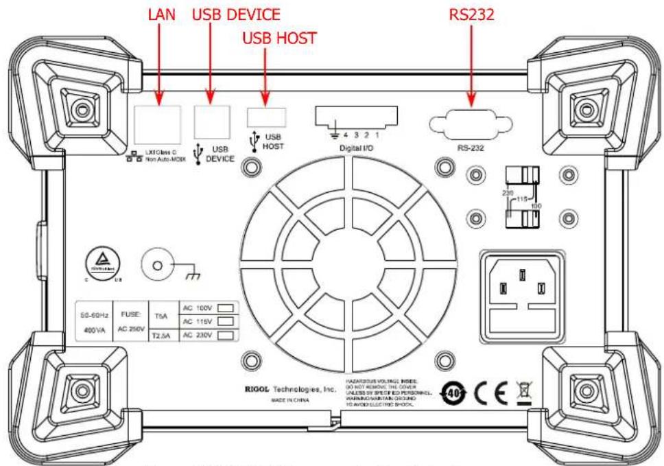
Figure 1-1 DP800 Communication Interfaces
Note: For DP832A/DP831A/DP822A/DP821A/DP813A/DP811A, the instrument is installed with the LAN and RS232 options when it leaves factory; users can build the remote communication between the instrument and PC via the LAN or RS232 interface directly. For DP832/DP831/DP822/DP821/DP813/DP811, the LAN interface communication and RS232 interface communication are optional functions; to use the functions, please order the corresponding option and install the option correctly (:LIC:SET).
(1) Use the USB interface: connect the USB DEVICE interface on the rear panel of DP800 and the USB HOST interface of the PC using USB cable.
(2) Use the LAN interface:
● Make sure that your PC is connected to the local network.
- Check whether your local network supports DHCP or auto IP mode. If not, you need to acquire the network interface parameters available, including the IP address, subnet mask, gateway and DNS.
- Connect DP800 to the local network using network cable.
- Press Utility → I/O Config → LAN to configure the IP address, subnet mask, gateway and DNS of the instrument.
(3) Use the RS232 interface:
- Connect the RS232 interface with the PC or data terminal equipment (DTE) using RS232 cable.
- Press Utility → I/O Config → RS232 to set interface parameters (such as the baud rate and parity) that match the PC or terminal equipment.
(4) Use the GPIB interface:
- Use the USB-GPIB interface converter to extend a GPIB interface via the USB HOST interface on the rear panel of DP800.
- Connect the instrument with your PC using a GPIB cable.
- Press Utility → I/O Config → GPIB to set the GPIB address of the instrument.
3 Check whether the connection is successful
Run the Ultra Sigma, search for resource, right-click the resource name and select "SCPI Panel Control" in the pop-up menu. Enter the correct command in the pop-up SCPI control panel and click "Send Command" and then "Read Response" or click "Send & Read" directly to check whether the connection is successful.
Remote Control Methods
1 User-defined Programming
You can program and control the instrument using the SCPI (Standard Commands for Programmable Instruments) commands listed in chapter 2 "Command System" in various development environments (such as Visual C++, Visual Basic and LabVIEW). For details, refer to the introductions in chapter 4 "Programming Demos".
2 Send SCPI Commands via the PC Software
It is recommended that you control the power supply remotely by sending SCPI commands via the PC software Ultra Sigma provided by RIGOL.
SCPI Command Overview
SCPI (Standard Commands for Programmable Instruments) is a standardized instrument programming language that is built upon the standard IEEE 488.1 and IEEE 488.2 and conforms to various standards (such as the floating point operation rules in IEEE754 standard, ISO646 7-bit coded character for information interchange (equivalent to ASCII programming)). This section introduces the syntax, symbols, parameters and abbreviation rules of the SCPI commands.
Syntax
SCPI commands present a hierarchical tree structure and contain multiple subsystems, each subsystem consists of a root keyword and one or more sub-keywords. The command string usually starts with ":"; the keywords are separated by ":" and are followed by the parameter settings available. The command keywords and the first parameter are separated by a space. "?" is added at the end of the command string to indicate query.
For example,
:SYSTem:COMMunicate:LAN:IPADdress
:SYSTem:COMMunicate:LAN:IPADdress?
SYSTem is the root keyword of the command. COMMunicate, LAN and IPADdress are the second-level, third-level and forth-level keywords respectively. The command string starts with ":" which is also used to separate the multiple-level keywords.
keywords :SYSTem:COMMunicate:LAN:IPADdress and parameter
", " is generally used for separating multiple parameters contained in the same command, for example, :DELAY:PARAMeter
Symbol Description
The following four symbols are not the content of SCPI commands and will not be sent with the commands. They are usually used to describe the parameters in the commands.
1 Braces {}
Usually, multiple optional parameters are enclosed in the braces and one of the parameters must be selected when sending the command. For example, :DISPLAY:MODE {NORMAL|WAVE|DIAL}.
2 Vertical Bar |
The vertical bar is used to separate multiple parameters and one of the parameters must be selected when sending the command. For example, :DISPLAY:MODE {NORMAL|WAVE|DIAL}.
3 Square Brackets [ ]
The content (command keyword) enclosed in the square brackets can be omitted. When the parameter is omitted, the instrument will set the parameter to its default. For example, for the :MEASure[:VOLTage][:DC]? command, sending any of the four commands below can achieve the same effect.
:MEASure?
:MEASure:DC?
:MEASure:VOLTage?
:MEASure:VOLTage:DC?
4 Triangle Brackets < >
The parameter enclosed in the triangle brackets must be replaced by an effective value. For example, send the :ANALyzer:CURRTime
Parameter Type
The parameters of the commands introduced in this manual contains 5 types: bool, integer, real number, discrete and ASCII string.
1 Bool
The parameter could be "ON" (1) or "OFF" (0). For example, :RECorder[:STATe] {ON|OFF}.
2 Integer
Unless otherwise noted, the parameter can be any integer within the effective value range. Note that do not set the parameter to a decimal; otherwise, errors will occur. For example, in the :SYSTem:BRIGHTness
3 Real Number
Unless otherwise noted, the parameter can be any real number within the effective value range. For example, for CH1 of DP831A, the ranges of
4 Discrete
The parameter could only be one of the specified values or characters. For example, in the :ANALyzer:OBJECT {V|C|P} command, the parameter can be V, C or P.
5 ASCII String
The parameter should be the combinations of ASCII characters. For example, in the :MMEMory:STORE
Besides, many commands contain the MINimum and MAXimum parameters which are used to set the parameter to its minimum or maximum value. For example, MINimum and MAXimum in the :SYSTem:BRIGHTness {
Command Abbreviation
All the commands are case-insensitive and you can use any of them. If abbreviation is used, all the capital letters in the command must be written completely. For example, the :ANALyzer:ANALyze command can be abbreviated to :ANAL:ANAL.
SCPI Status Registers
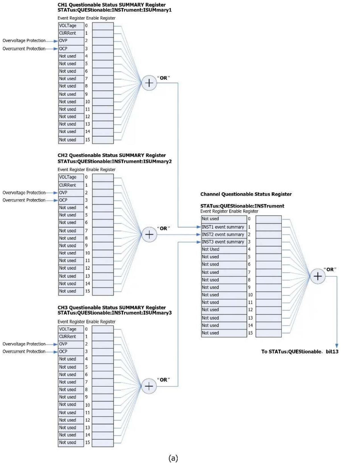
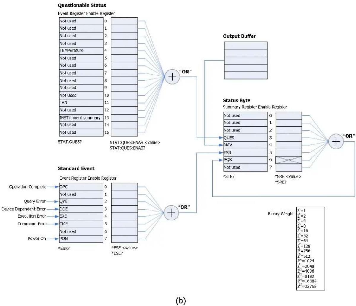
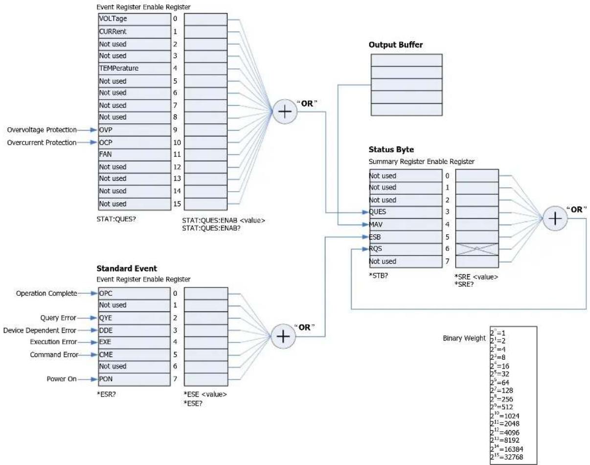
All the SCPI instruments execute the status register operations in the same way. The status system records the various instrument states into three register sets: status byte register, standard event register and questionable status register sets. The status byte register records the advanced summary information reported by other register sets. The SCPI status systems of the DP800 series multi-channel models (take DP831A as an example) and single-channel model (take DP811A as an example) are as shown in Figure 1-2 and Figure 1-3 respectively.
Event Register
The event register is read-only and is used to report some states of the power supply defined internally. All the bits in the event register are latched and once an event bit is set, the later state (state of the event represented by this bit) changes will all be ignored. The event register bits will be cleared automatically when you send command to query the event register (such as the *ESR? or :STATus:QUESTIONable[:EVENT]? command) or send the *CLS command to clear the register, but the reset command (*RST) will not clear the bits in the event register. When querying the event register, the query returns a decimal value corresponding to the sum of the binary weights of all the bits in the register.
Enable Register
The enable register is both readable and writable. It is used to define which status information will be reported to the next-level. The bits in the enable register will not be cleared when you send command to query the enable register or send the *CLS command to clear the register state (but the *CLS command can clear the bits in the event register). To enable the bits in the enable register, you need to write into the register a decimal value corresponding to the sum of the binary weights of the bits to be enabled in the register.
Multi-logic Output
This part is only applicable to multi-channel models. Take DP831A as an example. The 3-logic output of the power supply includes a channel questionable status register and three independent channel questionable status SUMMARY registers (corresponding to the logic outputs of the three channels respectively). The channel questionable status SUMMARY registers report the status of each channel to the channel questionable status register which then reports the channel status to the bit13 (ISUM bit) of the questionable status register.
flowchart
graph TD
    subgraph_CH1_QuestionableStatus["CH1 Questionable Status SUMMARY Register STATUS:QUESTIONABLE:INSTRUMENT:ISUMmary1"]
        A1["Overvoltage Protection"] --> A2["VOLTage 0"]
        A --> A3["CURRENT 1"]
        A --> A4["OVP 2"]
        A --> A5["OCP 3"]
        A --> A6["Not used 4"]
        A --> A7["Not used 5"]
        A --> A8["Not used 6"]
        A --> A9["Not used 7"]
        A --> A10["Not used 8"]
        A --> A11["Not used 9"]
        A --> A12["Not used 10"]
        A --> A13["Not used 11"]
        A --> A14["Not used 12"]
        A --> A15["Not used 13"]
        A --> A16["Not used 14"]
        A --> A17["Not used 15"]
    end

    subgraph_CH2_QuestionableStatus["CH2 Questionable Status SUMMARY Register STATUS:QUESTIONABLE:INSTRUMENT:ISUMmary2"]
        B1["Overvoltage Protection"] --> B2["VOLTage 0"]
        B --> B3["CURRENT 1"]
        B --> B4["OVP 2"]
        B --> B5["OCP 3"]
        B --> B6["Not used 4"]
        B --> B7["Not used 5"]
        B --> B8["Not used 6"]
        B --> B9["Not used 7"]
        B --> B10["Not used 8"]
        B --> B11["Not used 9"]
        B --> B12["Not used 10"]
        B --> B13["Not used 11"]
        B --> B14["Not used 12"]
        B --> B15["Not used 13"]
        B --> B16["Not used 14"]
        B --> B17["Not used 15"]
    end

    subgraph_CH3_QuestionableStatus["CH3 Questionable Status SUMMARY Register STATUS:QUESTIONABLE:INSTRUMENT:ISUMmary3"]
        C1["Overvoltage Protection"] --> C2["VOLTage 0"]
        C --> C3["CURRENT 1"]
        C --> C4["OVP 2"]
        C --> C5["OCP 3"]
        C --> C6["Not used 4"]
        C --> C7["Not used 5"]
        C --> C8["Not used 6"]
        C --> C9["Not used 7"]
        C --> C10["Not used 8"]
        C --> C11["Not used 9"]
        C --> C12["Not used 10"]
        C --> C13["Not used 11"]
        C --> C14["Not used 12"]
        C --> C15["Not used 13"]
        C --> C16["Not used 14"]
        C --> C17["Not used 15"]
    end

    subgraph_ChannelQuestionableStatus["Channel Questionable Status Register STATUS:QUESTIONABLE:INSTRUMENT Event Register Enable Register"]
        D1["INST1 event summary"] --> D2["INST2 event summary"] --> D3["INST3 event summary"] --> D4["NOT USED"] --> D5["NOT USED"] --> D6["NOT USED"] --> D7["NOT USED"] --> D8["NOT USED"] --> D9["NOT USED"] --> D10["NOT USED"] --> D11["NOT USED"] --> D12["NOT USED"] --> D13["NOT USED"] --> D14["NOT USED"] --> D15["NOT USED"] --> D16["NOT USED"] --> D17["NOT USED"] --> D18["NOT USED"] --> D19["NOT USED"] --> D20["NOT USED"] --> D21["NOT USED"] --> D22["NOT USED"] --> D23["NOT USED"] --> D24["NOT USED"] --> D25["NOT USED"] --> D26["NOT USED"] --> D27["NOT USED"] --> D28["NOT USED"] --> D29["NOT USED"] --> D30["NOT USED"] --> D31["NOT USED"] --> D32["NOT USED"] --> D33["NOT USED"] --> D34["NOT USED"] --> D35["NOT USED"] --> D36["NOT USED"] --> D37["NOT USED"] --> D38["NOT USED"] --> D39["NOT USED"] --> D40["NOT USED"] --> D41["NOT USED"] --> D42["NOT USED"] --> D43["NOT USED"] --> D44["NOT USED"] --> D45["NOT USED"] --> D46["NOT USED"] --> D47["NOT USED"] --> D48["NOT USED"] --> D49["NOT USED"] --> D50["NOT USED"] --> D51["NOT USED"] --> D52["NOT USED"] --> D53["NOT USED"] --> D54["NOT USED"] --> D55["NOT USED"] --> D56["NOT USED"] --> D57["NOT USED"] --> D58["NOT USED"] --> D59["NOT USED"] --> D60["NOT USED"] --> D61["NOT USED"] --> D62["NOT USED"] --> D63["NOT USED"] --> D64["NOT USED"] --> D65["NOT USED"] --> D66["NOT USED"] --> D67["NOT USED"] --> D68["NOT USED"] --> D69["NOT USED"] --> D70["NOT USED"] --> D71["NOT USED"] --> D72["NOT USED"] --> D73["NOT USED"] --> D74["NOT USED"] --> D75["NOT USED"] --> D76["NOT USED"] --> D77["NOT USED"] --> D78["NOT USED"] --> D79["NOT USED"] --> D80["NOT USED"] --> D81["NOT USED"] --> D82["NOT USED"] --> D83["NOT USED"] --> D84["NOT USED"] --> D85["NOT USED"] --> D86["NOT USED"] --> D87["NOT USED"] --> D88["NOT USED"] --> D89["NOT USED"] --> D90["NOT USED"] --> D91["NOT USED"] --> D92["NOT USED"] --> D93["NOT USED"] --> D94["NOT USED"] --> D95["NOT USED"] --> D96["NOT USED"] --> D97["NOT USED"] --> D98["NOT USED"] --> D99["NOT USED"] --> D100["To STATUS:QUESTIONABLE, bit13"]

    end
flowchart
graph TD
    A["Questionable Status"] --> B["Event Register Enable Register"]
    B --> C["Not used 0-15"]
    B --> D["TEMperature 2-4"]
    B --> E["FAN 11-15"]
    B --> F["INSTRument summary 7-13"]
    B --> G["NOT USED 14-15"]
    H["Standard Event"] --> I["Operation Complete OPC 0-1"]
    H --> J["Query Error QYE 2-3"]
    H --> K["Device Dependent Error DDE 3-4"]
    H --> L["Execution Error EXE 4-5"]
    H --> M["Command Error CME 5-6"]
    H --> N["Power On PON 7-*ESR?"]
    O["Output Buffer"] --> P["NOT USED 0-1"]
    O --> Q["NOT USED 1-2"]
    O --> R["NOT USED 2-3"]
    O --> S["NOT USED 3-4"]
    O --> T["NOT USED 4-5"]
    O --> U["NOT USED 5-6"]
    O --> V["NOT USED 6-7"]
    W["Status Byte"] --> X["Summary Register Enable Register"]
    X --> Y["NOT USED 0-1"]
    X --> Z["NOT USED 1-2"]
    X --> AA["NOT USED 2-3"]
    X --> AB["NOT USED 3-4"]
    X --> AC["NOT USED 4-5"]
    X --> AD["NOT USED 5-6"]
    X --> AE["NOT USED 6-7"]
    X --> AF["NOT USED 7-*STB?"]
    X --> AG["NOT USED 0-1"]
    X --> AH["NOT USED 1-2"]
    X --> AI["NOT USED 2-3"]
    X --> AJ["NOT USED 3-4"]
    X --> AK["NOT USED 4-5"]
    X --> AL["NOT USED 5-6"]
    X --> AM["NOT USED 6-7"]
    X --> AN["NOT USED 7-*SRE <value> *SRE?"]
    AO["Binary Weight"] --> AP["2=1, 2=2, 2=4, 2=8, 2=16, 2=32, 2=64, 2=128, 2=256, 2=512, 2=1024, 2=2048, 2=4096, 8192, 16384, 32768"]
Figure 1-2 The SCPI Status System of DP800 Series Multi-channel Models (Take DP831A as an Example)
flowchart
graph TD
    subgraph_Event_Register_Enable_Register["Event Register Enable Register"]
        A1["VOLTage"] --> B1["0"]
        A2["CURRENT"] --> B2["1"]
        A3["Not used"] --> B3["2"]
        A4["Not used"] --> B4["3"]
        A5["TEMPérature"] --> B5["4"]
        A6["Not used"] --> B6["5"]
        A7["Not used"] --> B7["6"]
        A8["Not used"] --> B8["7"]
        A9["Not used"] --> B9["8"]
        A10["Overvoltage Protection"] --> B10["OVP"]
        A11["Overcurrent Protection"] --> B11["OCP"]
        A12["FAN"] --> B12["11"]
        A13["Not used"] --> B13["12"]
        A14["Not used"] --> B14["13"]
        A15["Not used"] --> B15["14"]
        A16["STAT:QUES?"] --> B16["15"]
    end

    subgraph_Output_Buffer["Output Buffer"]
        C1[" "] --> D1["OR"]
        C2[" "] --> D2["OR"]
        C3[" "] --> D3["OR"]
        C4[" "] --> D4["OR"]
        C5[" "] --> D5["OR"]
        C6[" "] --> D6["OR"]
        C7[" "] --> D7["OR"]
        C8[" "] --> D8["OR"]
        C9[" "] --> D9["OR"]
        C10[" "] --> D10["OR"]
        C11[" "] --> D11["OR"]
        C12[" "] --> D12["OR"]
        C13[" "] --> D13["OR"]
        C14[" "] --> D14["OR"]
        C15[" "] --> D15["OR"]
        C16[" "] --> D16["OR"]
        C17[" "] --> D17["OR"]
        C18[" "] --> D18["OR"]
        C19[" "] --> D19["OR"]
        C20[" "] --> D20["OR"]
        C21[" "] --> D21["OR"]
        C22[" "] --> D22["OR"]
        C23[" "] --> D23["OR"]
        C24[" "] --> D24["OR"]
        C25[" "] --> D25["OR"]
        C26[" "] --> D26["OR"]
        C27[" "] --> D27["OR"]
        C28[" "] --> D28["OR"]
        C29[" "] --> D29["OR"]
        C30[" "] --> D30["OR"]
        C31[" "] --> D31["OR"]
        C32[" "] --> D32["OR"]
        C33[" "] --> D33["OR"]
        C34[" "] --> D34["OR"]
        C35[" "] --> D35["OR"]
        C36[" "] --> D36["OR"]
        C37[" "] --> D37["OR"]
        C38[" "] --> D38["OR"]
        C39[" "] --> D39["OR"]
        C40[" "] --> D40["OR"]
        C41[" "] --> D41["OR"]
        C42[" "] --> D42["OR"]
        C43[" "] --> D43["OR"]
        C44[" "] --> D44["OR"]
        C45[" "] --> D45["OR"]
        C46[" "] --> D46["OR"]
        C47[" "] --> D47["OR"]
        C48[" "] --> D48["OR"]
        C49[" "] --> D49["OR"]
        C50[" "] --> D50["OR"]
        C51[" "] --> D51["OR"]
        C52[" "] --> D52["OR"]
        C53[" "] --> D53["OR"]
        C54[" "] --> D54["OR"]
        C55[" "] --> D55["OR"]
        C56[" "] --> D56["OR"]
        C57[" "] --> D57["OR"]
        C58[" "] --> D58["OR"]
        C59[" "] --> D59["OR"]
        C60[" "] --> D60["OR"]
        C61[" "] --> D61["OR"]
        C62[" "] --> D62["OR"]
        C63[" "] --> D63["OR"]
        C64[" "] --> D64["OR"]
        C65[" "] --> D65["OR"]
        C66[" "] --> D66["OR"]
        C67[" "] --> D67["OR"]
        C68[" "] --> D68["OR"]
        C69[" "] --> D69["OR"]
        C70[" "] --> D70["OR"]
        C71[" "] --> D71["OR"]
        C72[" "] --> D72["OR"]
        C73[" "] --> D73["OR"]
        C74[" "] --> D74["OR"]
        C75[" "] --> D75["OR"]
        C76[" "] --> D76["OR"]
        C77[" "] --> D77["OR"]
        C78[" "] --> D78["OR"]
        C79[" "] --> D79["OR"]
        C80[" "] --> D80["OR"]
    end

    subgraph Status�Byte["Status Byte"]
        U1["Summary Register Enable Register"]
        V1["*STB?"] --> U2["*SRE <value> *SRE?"]
    end

    subgraph Standard_Event
        W1["Operation Complete"] --> W2["*ESR?"]
        W2 --> W3["*ESE <value> *ESE?"]
    end

    subgraph Binary Weight
            X1["Binary Weight 2^i=1, 2^i=2, 2^i=4, 2^i=8, 2^i=16, 2^i=32, 2^i=64, 2^i=128, 2^i=256, 2^i=512, 2^i=1024, 2^i=2048, 2^i=4096, 2^i=8192, 2^i=16384, 2^i=32768"]
    end
Figure 1-3 The SCPI Status System of DP800 Series Single-channel Model (Take DP811A as an Example)
Questionable Status Register
Questionable Status Register of Multi-channel Models
The SCPI status system of the multi-channel models is as shown in Figure 1-2. Wherein, the channel questionable status register indicates in which channel questionable event occurs. While for each specific logic output, the channel questionable status SUMMARY register is a pseudo-questionable status register.
The questionable status register provides information about the questionable status of the power supply. Bit4 (TEMPerature) reports the over-temperature state; bit11 (FAN) reports the fan failure state and bit13 (INSTrument summary) summaries the questionable output state of any of the three output channels. You can send the :STATUS:QUESTIONable[:EVENT]? command to read the register. To use bit13, you must first enable the register the information of which you want to summarize using bit13. Send the :STATUS:QUESTIONable:INSTrument:ENABLE command to enable the channel questionable status register; then send the :STATUS:QUESTIONable:INSTrument:
Table 1-1 Definitions of the bits in the questionable status register of the multi-channel models and the decimal values corresponding to their binary weights
| Bit | Decimal Value | Definition | |
| 0-3 Not used 0 Always be 0. | |||
| 4 | TEMPerature | 16 | Over-temperature. |
| 5-10 | Not used | 0 | Always be 0. |
| 11 | FAN | 2048 | Fan failure. |
| 12 | Not used | 0 | Always be 0. |
| 13 | INSTrument summary | 8192 | Summary information of the channel questionable status register and channel questionable status SUMMARY register set. |
| 14-15 | Not used | 0 | Always be 0. |
Channel Questionable Status Register
The channel questionable status register provides the questionable status information of all the three channels. Bit1 (INST1 event summary), bit2 (INST2 event summary) and bit3 (INST3 event summary) report the information about the questionable states of CH1, CH2 and CH3 respectively. You can send the :STATus:QUESTIONable:INSTrument[:EVENT]? command to read the register. To use the channel questionable status register, you must enable the channel questionable status SUMMARY register. You can send the :STATus:QUESTIONable:INSTrument:ISUMmary[
Table 1-2 Definitions of the bits in the channel questionable status register of the multi-channel model and the decimal values corresponding to their binary weights
| Bit Decimal Value Definition | |||
| 0 Not used | 0 Always be 0. | ||
| 1 | INST1 event summary | 2 | Summary information of CH1 events. |
| 2 | INST2 event summary | 4 | Summary information of CH2 events. |
| 3 | INST3 event summary | 8 | Summary information of CH3 events. |
| 4-15 Not used | 0 Always be 0. | ||
Channel Questionable Status SUMMARY Register
DP831A provides 3 channel questionable status SUMMARY registers corresponding to the three channels respectively. The channel questionable status SUMMARY register provides the channel voltage control, current control, overvoltage and overcurrent information. When the voltage becomes unregulated, bit0 (VOLTage) is set; when the current becomes unregulated, bit1 (CURRENT) is set. You can send the :STATUS:QUESTIONable:INSTrument:ISUMmary[
Table 1-3 Definitions of the bits in the channel questionable status SUMMARY register of the multi-channel model and the decimal values corresponding to their binary weights
| Bit | Decimal Value | Definition | |
| 0 VOLTage | 1 | The power supply is working in constant current mode and the voltage becomes unregulated. | |
| 1 CURRENT | 2 | The power supply is working in constant voltage mode and the current becomes unregulated. | |
| 2 | OVP | 4 | Overvoltage. |
| 3 OCP | 8 | Overcurrent. | |
| 4-15 | Not used | 0 | Always be 0. |
You can send the :STATus:QUESTIONable:INSTrument:ISUMmary[
Questionable Status Register of Single-channel Model
The SCPI status system of the single-channel model is as shown in Figure 1-3. Wherein, the questionable status register provides voltage control, current control, over-temperature, overvoltage, overcurrent and fan failure information. You can send the :STATUS:QUESTIONable[:EVENT]? command to read the register. The definitions of the bits in the questionable status register of the single-channel model and the decimal values corresponding to their binary weights are as shown in Table 1-4.
Table 1-4 Definitions of the bits in the questionable status register of the single-channel model and the decimal values corresponding to their binary weights
| Bit Decimal Value Definition | |||
| 0 VOLTage 1 | The power supply is working in constant current mode and the voltage becomes unregulated. | ||
| 1 CURRENT 2 | The power supply is working in constant voltage mode and the current becomes unregulated. | ||
| 2-3 Not used 0 Always be 0. | |||
| 4 | TEMPerature | 16 | Over-temperature. |
| 5-8 Not used 0 Always be 0. | |||
| 9 | OVP | 512 | Overvoltage. |
| 10 | OCP | 1024 | Overcurrent. |
| 11 | FAN | 2048 | Fan failure. |
| 12-15 | Not used | 0 | Always be 0. |
Standard Event Register
The standard event register reports the following instrument events: power-on detection command syntax error, command execution error, self-test or calibration error, query error or operation complete. All these events or anyone of these events can be reported by the enable register to the bit5 (ESB, Event Summary Bit) of the status byte register. To set the enable register mask, you need to use the *ESE command to write a decimal value into the register. The definitions of the bits in the standard event register and the corresponding decimal values of their binary weights are as shown in Table 1-5.
Note: An error status (bit2, 3, 4 or 5 in the standard event register) records one or more errors in the power supply error queue and you can send the :SYSTem:ERRor? command to read the error queue.
Table 1-5 Definitions of the bits in the standard event register and the corresponding decimal values of their binary weights
| Bit | Decimal Value | Definition | |
| 0 OPC 1 | Operation complete. All the previous commands including the *OPC command are executed. | ||
| 1 Not used 0 Always be 0. | |||
| 2 QYE 4 | Query error. The power supply tries to read the output buffer but it is empty; or the system receives a new command before the previous query command is read; or both the input and output buffers are full. | ||
| 3 | DDE | 8 | Device error. Self-test or calibration error occurs. |
| 4 EXE | 16 | Execution error (include trigger ignore, initialization ignore, setting conflict, data overrange, data too long and invalid parameter value). | |
| 5 | CME | 32 | Command error. Command syntax error occurs. |
| 6 Not used 0 Always be 0. | |||
| 7 PON | 128 | Power-on inspection. Turn off the power supply after the event register is read or cleared and then turn on the power supply. | |
The status byte register reports the status information of the other status registers. The bit4 (MAV, Message Available Bit) in the status byte register will report immediately when querying the data waiting to be queried in the output buffer of the power supply. The bits in the SUMMARY register of the status byte register are not latched. The corresponding bit in the SUMMARY register of the status byte register will be cleared when the event register is cleared. The bit4 (MAV, Message Available Bit) will be cleared when reading all the information including any pending queries in the output buffer. The definitions of the bits in the status byte register and the corresponding decimal values of their binary weights are as shown in Table 1-6.
Table 1-6 Definitions of the bits in the status byte register and the corresponding decimal values of their binary weights
| Bit | Decimal Value | Definition | |
| 0-2 Not used 0 Always be | 0. | ||
| 3 QUES 8 | One or more bits in the questionable status register are set (the bits in the enable register must be enabled) | ||
| 4 MAV 16 | The data in the output buffer of the power supply is available. | ||
| 5 ESB | 32 | One or more bits in the standard event register are set (the bits in the enable register must be enabled) | |
| 6 | RQS | 64 | The power supply is requesting for service. |
| 7 Not used 0 Always be 0. | |||
Chapter 2 Command System
This chapter introduces the syntax, function, parameter and using instruction of each DP800 command in A-Z order.
Main topics of this chapter:
◆ :ANALyzer Commands
◆ :APPLy Command
◆ :DELAY Commands
◆ :DISPLAY Commands
IEEE488.2 Common Commands
◆ : INITiate Command
◆ :INSTrument Commands
◆ :LIC Command
◆ :MEASure Commands
◆ :MEMory Commands
◆ :MMEMory Commands
◆ :MONItor Commands
◆ :OUTPut Commands
◆ :PRESet Commands
◆ :RECALL Commands
◆ :RECorder Commands
◆ :SOURce Commands
◆ :STATus Commands
◆ :STORe Commands
◆ :SYSTem Commands
◆ :TIMEr Commands
:TRIGger Commands
Explanation: In this command system, setting commands relating to the time, voltage, current and power parameters can be sent with units. Unless otherwise noted, the units available and the default unit of each parameter are as shown in the table below.
| Parameter Type | Units Available | Default Unit |
| Time | s^[1] | s |
| Voltage | V, mV | V |
| Current | A, mA | A |
| Power | W, mW | W |
Note ^[1] : For the :TRIGger:OUT:PERIod [D0|D1|D2|D3,]
:ANALyzer Commands
The :ANALyzer commands are used to set the analyzer parameters, execute analysis and query the analysis results.
For DP832A/DP831A/DP822A/DP821A/DP813A/DP811A, the instrument is installed with the analyzer option when it leaves factory and users can directly use the analyzer function. For DP832/DP831/DP822/DP821/DP813/DP811, the analyzer is an optional function; to use this function, please order the corresponding option and install the option correctly (:LIC:SET).
Command List ^[1] :
◆ :ANALyzer:ANALyze
◆ :ANALyzer:CURRTime
◆ :ANALyzer:ENDTime
◆ :ANALyzer:FILE?
:ANALyzer:MEMory
:ANALyzer:MMEMory
◆ :ANALyzer:OBJECT
◆ :ANALyzer:RESult?
◆ :ANALyzer:STARTTime
:ANALyzer:VALue?
:ANALyzer:ANALyze
| Syntax | :ANALyzer:ANALyze |
| Description | When receiving this command, the instrument executes the analysis operation according to the current setting. |
| Explanation | The analysis operation can only be executed when valid record file is opened (:ANALyzer:FILE?).You can send the :ANALyzer:RESult? command to view the analysis results. |
| Related Commands | :ANALyzer:FILE?:ANALyzer:RESult? |
Note ^[1] : In the "Command List" in this manual, the parameters in the setting commands and the query commands are not included and you can view the complete introductions of the commands in the text according to the keywords.
:ANALyzer:CURRTime
Syntax :ANALyzer:CURRTime
:ANALyzer:CURRTime?
Description Set the current time of the analyzer.
Query the current time of the analyzer.
Parameter
| Name | Type | Range | Default |
| Integer | Start time to end time of the record file opened | Start time |
Explanation You can only set the current time when valid record file is opened (:ANALyzer:FILE?).
Return Format The query returns an integer, for example, 12.
Example :ANAL:CURRT 12 /*Set the current time of the analyzer to 12s*/
:ANAL:CURRT? /*Query the current time of the analyzer and the query returns 12*/
Related :ANALyzer:FILE?
Commands :ANALyzer:STARTTime
:ANALyzer:ENDTime
:ANALyzer:ENDTime
Syntax :ANALyzer:ENDTime {
:ANALyzer:ENDTime? [MINimum|MAXimum]
Description Set the end time of the analyzer.
Query the end time of the analyzer.
Parameter
| Name | Type | Range | Default |
| Integer | Refer to the "Explanation" | ||
Explanation
You can only set the end time when valid record file is opened (refer to the :ANALyzer:FILE? command).
When the groups of the record file opened is less than or equal to 2048, the range of the end time is from the start time to the maximum record time (groups times record period) of the record file opened and the default is the maximum record time of the record file opened.
When the groups of the record file opened is greater than 2048, the range of the end time is from the start time to the product of the record period of the record file opened times 2048 and the default is the product of the record period of the record file opened times 2048.
When receiving the :ANALyzer:ANALyze command, the analyzer will analyze the recorded data between the start time and end time.
Return Format The query returns an integer, for example, 125.
Example :ANAL:ENDT 125
/*Set the end time of the analyzer to 125s*/
:ANAL:ENDT?
/*Query the current end time and the query returns 125*/
Related :ANALyzer:ANALyze
Commands
:ANALyzer:FILE?
:ANALyzer:STARTTime
:ANALyzer:FILE?
Syntax :ANALyzer:FILE?
Description Query the record file currently opened.
Return Format When valid record file is currently opened, the query returns the directory of the file currently opened, for example, C:\REC 10:test.ROF; when no valid record file is currently opened, the query returns NULL.
:ANALyzer:MEMory
Syntax :ANALyzer:MEMory {1|2|3|4|5|6|7|8|9|10}
Description Open the specified record file in the internal memory (C disk).
| Parameter | Name | Type | Range | Default |
| {1|2|3|4|5|6|7|8|9|10} | Discrete | 1|2|3|4|5|6|7|8|9|10 | None | |
| Explanation | This command is only available when valid record file is stored in the specified location. | |||
| Parameters 1 to 10 represent the record files stored in the corresponding locations of the internal memory respectively. | ||||
| You can only set the start time, end time, current time and analysis object as well as execute the analysis operation when valid record file is currently opened (:ANALyzer:FILE?). | ||||
| Example | :ANAL:MEMory 10 /*Open the record file currently stored in record file storage location 10 in C disk*/ | |||
| Related | :ANALyzer:FILE? | |||
| Commands | :ANALyzer:STARTTime | |||
| :ANALyzer:ENDTime | ||||
| :ANALyzer:CURRTime | ||||
| :ANALyzer:ANALyze | ||||
:ANALyzer:MMEMory
Syntax :ANALyzer:MMEMory
Description Open the record file in the specified directory in the external memory (D disk).
| Parameter | Name | Type | Range | Default |
| ASCII string | Valid directory under D disk | |||
| Explanation | This command is only available when external memory is detected and valid record file is stored in the specified directory of the external memory.You can only set the start time, end time, current time and analysis object as well as execute the analysis operation when valid record file is currently opened (:ANALyzer:FILE?). | |||
| Example | :ANAL:MMEMory D:\RECORD.ROF /*Open the RECORD.ROF file under D disk*/ | |||
| Related | :ANALyzer:FILE? | |||
| Commands | :ANALyzer:STARTTime | |||
| :ANALyzer:ENDTime | ||||
| :ANALyzer:CURRTime | ||||
| :ANALyzer:ANALyze | ||||
:ANALyzer:OBJECT
Syntax :ANALyzer:OBJECT {V|C|P}
:ANALyzer:OBJECT?
Description Set the analysis object of the analyzer to voltage, current or power.
Query the analysis object of the analyzer.
| Parameter | Name | Type | Range | Default |
| {V|C|P} | Discrete | V|C|P | V |
Explanation You can only set the analysis object when valid record file is opened (refer to the :ANALyzer:FILE? command).
Return Format The query returns V, C or P.
Example :ANAL:OBJ V /*Set the analysis object of the analyzer to voltage*/
:ANAL:OBJ? /*Query the analysis object of the analyzer and the query returns V*/
Related :ANALyzer:FILE?
Command
:ANALyzer:RESult?
Syntax :ANALyzer:RESult?
Description Query the analysis results, including the number of groups, median, mode, average, variance, range, minimum, maximum and mean deviation.
Return Format The query returns the analysis results with the data separated by commas, for example, Group:85, Median:41.9994V, Mode:0.0000V, Average:34.0924V, Variance:269.5170V, Range:42.0002V, Min:0.0000V, Max:42.0002V, Mean:12.8347V.
Example :ANAL:RES? /*Query the analysis results and the query returns Group:85,Median:41.9994V,Mode:0.0000V,Average:34.0924V,Variance:269.5170V,Range:42.0002V,Min:0.0000V,Max:42.0002V,Mean:12.8347V*/
Related :ANALyzer:ANALyze
Command
:ANALyzer:STARTTime
Syntax :ANALyzer:STARTTime {
:ANALyzer:STARTTime? [MINimum|MAXimum]
Description Set the start time of the analyzer.
Query the start time of the analyzer.
| Parameter | Name | Type | Range | Default |
| Integer | Record period of the record file opened to end time | Record period of the record file opened | ||
Explanation ➤ You can only set the start time when valid record file is opened (refer to the :ANALyzer:FILE? command).
Send the :ANALyzer:ANALyze command and the analyzer analyzes the recorded data between the start time and end time.
Return Format The query returns an integer, for example, 1.
Example :ANAL:STARTT 1 /*Set the start time to 1s*/
:ANAL:STARTT? /*Query the current start time and the query returns 1*/
Related :ANALyzer:ANALyze Commands :ANALyzer:EILF2
:ANALyzer:FILE?
:ANALyzer:ENDTime
:ANALyzer:VALue?
Syntax :ANALyzer:VALue?
Description Query the voltage, current and power at the specified time in the record file opened.
| Parameter | Name | Type | Range | Default |
| Integer | Start time of the record file opened to end time | None | ||
Explanation This command is only valid when valid record file is opened (refer to the :ANALyzer:FILE? command).
Return Format The query returns the voltage, current and power separated by commas, for example, Volt:1.2817V, Curr:0.0485A, Power:0.0622W.
Example :ANAL:VAL? 5 /*Query the voltage, current and power at 5s of the record file opened and the query returns Volt:1.2817V,Curr:0.0485A,Power:0.0622W*/
Related :ANALyzer:ENDTime Commands :ANALyzer:FILE?
:ANALyzer:STARTTime
:APPLy Command
The :APPLy command provides the most straightforward method to program the power supply over the remote interface. For the multi-channel models, you can select the specified channel and set the voltage and current in a single command; for the single-channel model, you can set the voltage and current in a single command. When the setting values are within the parameter ranges of the corresponding channel (multi-channel models) or range (single-channel model) of the specified model, the output voltage and current will change to the setting values immediately after executing this command. The voltage/current ranges and default values of each channel (multi-channel models) or range (single-channel model) of different models are as shown in the table below.
Table 2-1 Voltage/current ranges and default values of each channel (range) of different models of DP800 series
| Channel (Range) | Voltage/Current Settable Range | Voltage/Current Default Value | |
| DP832A | CH1 (30V/3A) | 0V to 32V/0A to 3.2A | 00.000V/3.000A |
| CH2 (30V/3A) | 0V to 32V/0A to 3.2A | 00.000V/3.000A | |
| CH3 (5V/3A) | 0V to -5.3V/0A to 3.2A | 0.000V/3.000A | |
| DP831A | CH1 (8V/5A) | 0V to 8.4V/0A to 5.3A | 0.000V/5.0000A |
| CH2 (30V/2A) | 0V to 32V/0A to 2.1A | 00.000V/2.0000A | |
| CH3 (-30V/2A) | 0V to -32V/0A to 2.1A | 00.000V/2.0000A | |
| DP822A | CH1 (20V/5A) | 0V to 21V/0A to 5.3A | 00.000V/5.000A |
| CH2 (5V/16A) | 0V to 5.3V/0A to 16.4A | 0.000V/16.000A | |
| DP821A | CH1 (60V/1A) | 0V to 63V/0A to 1.05A | 00.000V/1.0000A |
| CH2 (8V/10A) | 0V to 8.4V/0A to 10.5A | 0.000V/10.000A | |
| DP813A | Range1 (8V/20A) | 0V to 8.4V/0A to 21A | 0.000V/20.000A |
| Range2 (20V/10A) | 0V to 21V/0A to 10.5A | ||
| DP811A | Range1 (20V/10A) | 0V to 21V/0A to 10.5A | 00.000V/05.0000A |
| Range2 (40V/5A) | 0V to 42V/0A to 5.3A | ||
| DP832[1] | CH1 (30V/3A) | 0V to 32V/0A to 3.2A | 00.00V/3.000A |
| CH2 (30V/3A) | 0V to 32V/0A to 3.2A | 00.00V/3.000A | |
| CH3 (5V/3A) | 0V to -5.3V/0A to 3.2A | 0.00V/3.000A | |
| DP831[1] | CH1 (8V/5A) | 0V to 8.4V/0A to 5.3A | 0.000V/5.000A |
| CH2 (30V/2A) | 0V to 32V/0A to 2.1A | 00.00V/2.000A | |
| CH3 (-30V/2A) | 0V to -32V/0A to 2.1A | 00.00V/2.000A | |
| DP822[1] | CH1 (20V/5A) | 0V to 21V/0A to 5.3A | 00.00V/5.00A |
| CH2 (5V/16A) | 0V to 5.3V/0A to 16.4A | 0.00V/16.00A | |
| DP821[1] | CH1 (60V/1A) | 0V to 63V/0A to 1.05A | 00.00V/1.000A |
| CH2 (8V/10A) | 0V to 8.4V/0A to 10.5A | 0.00V/10.00A | |
| DP813[1] | Range1 (8V/20A) | 0V to 8.4V/0A to 21A | 00.00V/20.00A |
| Range2 (20V/10A) | 0V to 21V/0A to 10.5A | ||
| DP811[1] | Range1 (20V/10A) | 0V to 21V/0A to 10.5A | 00.00V/05.00A |
| Range2 (40V/5A) | 0V to 42V/0A to 5.3A | ||
Note ^[1] : When DP832 (DP831, DP822, DP821, DP813, or DP811) is installed with the high resolution option, its voltage/current settable range and default value of each channel are the same with those of DP832A (DP831A, DP822A, DP821A, DP813A, or DP811A).
:APPLY
Syntax
:APPLy {CH1|CH2|CH3}
[,
Description
Select the specified channel as the current channel and set the voltage/current of this channel.
Set the voltage/current of the current channel.
Query the voltage/current of the specified channel.
Parameter
| Name | Type | Range | Default |
| 1|CH2|CH3\^[1] | Discrete | CH1|CH2|CH3 | None |
| Real | Refer to Table 2-1 | ||
| Real | Refer to Table 2-1 | ||
| [CH1|CH2|CH3] | Discrete | CH1|CH2|CH3 | None |
| [CURRENT|VOLTag e] | Discrete | CURRENT|VOLTage | None |
Explanation
For the multi-channel models, this command is used to select the specified channel and set the voltage and current; for the single-channel model, this command is used to set the voltage and current of the channel. This command combines the channel select command (:INSTrument:NSELect, :INSTrument[:SELECT] or :INSTrument[:SELECT], only applicable to the multi-channel models), voltage setting command ([:SOURce[
In the query command, the parameter [CH1|CH2|CH3] is used to select the channel to be query. If it is ignored, the current channel will be query.
You can use MINimum, MAXimum or DEF which denote setting the voltage or current of the specified channel (range) to the minimum, maximum or default instead of the specified voltage (
[CURRENT|VOLTage] is used to select to query the voltage or current of the specified channel. If they are both omitted, the system will query both the voltage and current of the specified channel.
In the query command, you can omit both of the parameters or only omit [CURRENT|VOLTage]; but you cannot only omit [CH1|CH2|CH3].
Return Format
The query returns a string.
The query returns the voltage or current setting value of the specified channel when [CH1|CH2|CH3] and [CURRENT|VOLTage] are specified, for example, 5.000.
The query returns the channel (range) name, rated voltage/current value, voltage setting value and current setting value of the specified channel
(multi-channel models) or current range (single-channel model) when only [CH1|CH2|CH3] is specified, for example, CH1:8V/5A,5.000,1.0000.
The query returns the voltage setting value and current setting value of the current channel (multi-channel models) or current range (single-channel model) when all the parameters are omitted, for example, 5.000,1.0000.
Example :APPL CH1,5,1 /*Set the voltage and current of CH1 to 5V and 1A respectively*/ :APPL? CH1 /*Query the voltage and current setting values of CH1 and the query returns CH1:8V/5A,5.000,1.0000*/
Related :INSTrument:NSELECT
Commands :INSTrument[:SELECT]
:INSTrument[:SELECT]
[:SOURce[
Note ^[1] : In this command system, commands that can use channel names (such as CH1 and CH2) as parameters can also use channel ranges (such as P8V and P30V) as parameters unless otherwise noted. The corresponding relations of the channel name parameters and channel range parameters supported by DP800 series are as follows.
DP831A/DP831: CH1---P8V; CH2---P30V; CH3---N30V DP832A/DP832: CH1---P30V; CH2---P30V2; CH3---P5V DP822A/DP822: CH1---P20V; CH2---P5V DP821A/DP821: CH1---P60V; CH2---P8V
:DELAY Commands
The :DELAY commands are used to set the delayer parameters (such as the number of groups, number of cycles and end state) as well as enable or disable the delayer.
Command List:
◆ :DELAY:CYCLEs
◆ :DELAY:ENDState
◆ :DELAY:GROUPs
◆ :DELAY:PARAMeter
◆ :DELAY[:STATE]
:DELAY:STATE:GEN
◆ :DELAY:STOP
◆ :DELAY:TIME:GEN
:DELAY:CYCLEs
Syntax :DELAY:CYCLEs {N|I}[,
:DELAY:CYCLEs?
Description Set the number of cycles of the delayer.
Query the number of cycles of the delayer.
Parameter
| Name | Type | Range | Default |
| {N|I} | Discrete | N|I | N |
| Integer | 1 to 99999 | 1 |
Explanation
The number of cycles refers to the number of times that the instrument performs delay output according to the preset state. Wherein, I represents infinite number of cycles; N represents finite number of cycles. The number of cycles is specified by
The total number of groups of the delay output = the number of groups × the number of cycles; wherein, the number of groups is set by the :DELAY:GROUPs command.
The power supply will terminate the delayer function when the total number of groups of delays is finished or when the state that meets the "stop condition" (the :DELAY:STOP command) is detected. At this point, the state of the power supply depends on the setting of the :DELAY:ENDState command.
Return Format The query returns I or N,
Example :DELAY:CYCLE I
/*Set the number of cycles to "Infinite" */
:DELAY:CYCLE N
/*Set the number of cycles to 1*/
:DELAY:CYCLE N,100
/*Set the number of cycles to 100*/
:DELAY:CYCLE?
/*Query the current number of cycles and the query returns N,100*/
Related :DELAY:GROUPs
Commands
:DELAY:STOP
:DELAY:ENDState
:DELAY:ENDState
Syntax :DELAY:ENDState {ON|OFF|LAST}
:DELAY:ENDState?
Description Set the end state of the delayer.
Query the end state of the delay e r.
| Parameter | Name | Type | Range | Default |
| {ON|OFF|LAST} | Discrete | ON|OFF|LAST | OFF |
Explanation ➤ The end state refers to the state of the instrument when the delayer stops. The power supply will terminate the delayer function when the total number of groups of delays is finished or when the state that meets the "stop condition" (the :DELAY:STOP command) is detected.
ON: output on, the instrument turns on the output automatically; OFF: output off, the instrument turns off the output automatically; LAST: last state, the instrument stops at the output state of the last group.
The total number of groups of the delay output = the number of groups × the number of cycles. Wherein, the number of groups is set by the :DELAY:GROUPs command and the number of cycles is set by the :DELAY:CYCLEs command.
Return Format The query returns ON, OFF or LAST.
Example :DELAY:ENDS LAST /*Set the end state of the delayer to Last*/
:DELAY:ENDS? /*Query the current end state of the delayer and the query returns LAST*/
Related :DELAY:STOP
Commands :DELAY:GROUPs
:DELAY:CYCLEs
:DELAY:GROUPs
Syntax :DELAY:GROUPs
:DELAY:GROUPs?
Description Set the number of output groups of the delayer.
Query the number of output groups of the delayer.
Parameter
| Name | Type | Range | Default |
| Integer | 1 to 2048 | 1 |
Explanation
The number of output groups refers to the number of times that the instrument turns on or off the output according to the preset state.
The total number of groups of the delay output = the number of groups × the number of cycles. Wherein, the number of cycles is set by the :DELAY:CYCLEs command.
The power supply will terminate the delayer function when the total number of groups of delays is finished or when the state that meets the "stop condition" (the :DELAY:STOP command) is detected. At this point, the state of the power supply depends on the setting of the :DELAY:ENDState command.
Return Format The query returns an integer from 1 to 2048.
Example
:DELAY:GROUP 125 /*Set the number of groups to 125*/
:DELAY:GROUP?
/*Query the current number of groups and the query returns 125*/
Related
:DELAY:CYCLEs
Commands
:DELAY:STOP
:DELAY:ENDState
:DELAY:PARAMeter
Syntax :DELAY:PARAMeter
:DELAY:PARAMeter?
Description Set the delayer parameters of the specified group.
Query the delayer parameters of the specified groups.
Parameter
| Name | Type | Range | Default |
| Integer | 0 to 2047 | None | |
| {ON|OFF} Bool ON|OFF | OFF (even group); ON (odd group) | ||
| Integer | 1s to 99999s | 1s | |
| Integer | 0 to 2047 | None | |
| Integer | 1 to 2048 | 1 | |
Explanation
Return Format The query returns a string starting with #. For example, #90000000152,OFF,3;3,ON,1;; wherein, #9000000015 is the data block header; 2,OFF,3;3,ON,1; are the actual delayer parameters.
The data block header is used to describe the data stream length information and starts with #. For example, the number "9" in #9000000015 denotes that the 9-bit data (000000015) following it is used to denote the data stream length (15 bytes).
The format of each group of delayer parameters is "number,output state,delay time"; multiple groups of parameters are separated by";". For example, 2,OFF,3;3,ON,1; denotes there are two groups of delayer parameters; the number of the first group of delayer parameters is 2, the output state is OFF and the delay time is 3s; the number of the second group of delayer parameters is 3, the output state is ON and the delay time is 1s.
Example :DELAY:PARA 1,ON,2 /*Set the delayer parameters of the first group. Set the state of the first group to ON and the delay time to 2s*/
:DELAY:PARA? 3,2 /*Query two groups of delayer parameters starting from the third group. The query returns #90000000153,ON,1;4,OFF,1;*/
:DELAY[:STATE]
Syntax :DELAY[:STATE] {ON|OFF}
:DELAY[:STATE]?
Description Enable or disable the delay output function of the current channel.
Query the state of the delay output function of the current channel.
| Parameter | Name | Type | Range | Default |
| {ON|OFF} | Bool | ON|OFF | OFF |
Explanation ➤ Enabling the delayer will change the output state of the channel. Make sure that the devices connected to the power supply will not be affected by the change of the output status before enabling the delayer.
The delayer parameters cannot be modified when the delayer is enabled.
For the multi-channel models, you can send the :INSTrument:NSELECT, :INSTrument[:SELECT] or :INSTrument[:SELECT] command to switch the current channel, set the delayer parameters of the current channel and enable or disable the delayer.
The timer (:TIMEr[:STATe]) and delayer cannot be enabled at the same time.
Return Format The query returns ON or OFF.
Example :DELAY ON /*Enable the delay output*/
:DELAY? /*Query the status of the delay output and the query returns ON*/
Related :INSTrument:NSELect
Commands :INSTrument[:SELECT]
:INSTrument[:SELECT]
:TIMEr[:STATe]
:DELAY:STATE:GEN
Syntax :DELAY:STATE:GEN {01P|10P}
:DELAY:STATE:GEN?
Description Select the pattern used when generating state automatically.
Query the pattern used when generating state automatically.
| Parameter | Name | Type | Range | Default |
| {01P|10P} | Discrete | 01P|10P | 01P |
Explanation ➤ 01P: 0 1 pattern. The state is set to "Off" and "On" alternately.
➢ 10P: 1 0 pattern. The state is set to "On" and "Off" alternately.
Return Format The query returns 01P or 10P.
Example :DELAY:STAT:GEN 10P /*Select 1 0 pattern*/
:DELAY:STAT:GEN? /*Query the pattern used when generating state automatically and the query returns 10P*/
:DELAY:STOP
Syntax :DELAY:STOP {NONE|
:DELAY:STOP? [MINimum|MAXimum]
Description Set the stop condition of the delayer.
Query the stop condition of the delayer.
Parameter
| Name | Type | Range | Default |
| {NONE|V|C|P} | Discrete | NONE|V|C|P | NONE |
| Real | 0 to the maximum voltage/current/power of the current channel | 0V/0A/0W |
Explanation
The power supply monitors the output voltage, current and power during delay output. Use this command to set a stop condition and the delay output stops when state that fulfills this condition is detected.
"NONE", "
Return Format The query returns NONE or "stop condition, value", for example, >V,8.000.
Example :DELAY:STOP >V,8 /*Set the stop condition of the delayer to ">8V"*/
:DELAY:STOP? /*Query the current stop condition of the delayer and the query returns >V,8.000*/
:DELAY:TIME:GEN
Syntax :DELAY:TIME:GEN {FIX|INC|DEC}[,
:DELAY:TIME:GEN?
Description Set the method used to generate time automatically and the corresponding parameters.
Query the method used to generate time automatically as well as the corresponding parameters.
| Parameter | Name | Type | Range | Default |
| {FIX|INC|DEC} | Discrete | FIX|INC|DEC | FIX | |
| Integer | Refer to the "Explanation" | 1s | ||
| Integer | Refer to the "Explanation" | 1s | ||
Explanation ➤ When FIX (fixed time) is selected, you can set the on delay (
When INC (monotonic increase) or DEC (monotonic decline) is selected, the duration is generated following the monotonic increase or monotonic decline rule, namely the time is generated by increasing or declining at the step from the time base value. You can set the time base value (
When
Return Format The query returns a string in "the method used to generate time automatically,
Example :DELAY:TIME:GEN INC,2,5 /*Set the method used to generate time automatically to monotonic increase, the time base value to 2s and the step to 5s*/
:DELAY:TIME:GEN? /*Query the method used to generate time automatically and the parameters; the query returns INC,2,5*/
Related :DELAY:GROUPs Command
:DISPLAY Commands
The :DISPLAY commands are used to set the display mode, turn on or off the screen display, display and clear the string on the screen.
Command List:
◆ :DISPLAY:MODE
◆ :DISPLAY[:WINDOW][:STATE]
◆ :DISPLAY[:WINDow]:TEXT:CLEar
◆ :DISPLAY[:WINDOW]:TEXT[:DATA]
:DISPLAY:MODE
Syntax :DISPLAY:MODE {NORMAL|WAVE|DIAL|CLAS}
:DISPLAY:MODE?
Description Set the display mode.
Query the current display mode.
Parameter
| Name | Type | Range | Default |
| {NORMAL|WAVE|DIAL|CLAS} | Discrete | NORMAL|WAVE|DIAL|CLAS | NORMAL |
Explanation
DP831A/DP832A provide four display modes: number, waveform, dial and classic. DP831/DP832/DP822A/DP822/DP821A/DP821/DP813A/DP813/DP811A/DP811 provide three display modes: number, waveform and dial.
➢ NORMAL: number mode. The parameters (such as the voltage and current) of all the channels are displayed in number format.
WAVE: waveform mode. The parameters (such as the voltage and current) of the channel currently selected are displayed in both waveform and number formats.
DIAL: dial mode. The parameters (such as the voltage and current) of the channel currently selected are displayed in both dial and number formats.
CLAS: classic mode. The parameters (such as the voltage and current) of all the channels are displayed in number (classic) format.
Return Format The query returns NORMAL, WAVE, DIAL or CLASSIC.
Example
:DISP:MODE WAVE /*Select the waveform display mode*/ :DISP:MODE? /*Query the current display mode and the query returns WAVE*/
:DISPLAY[:WINDOW][:STATE]
Syntax :DISPLAY[:WINDOW][:STATE] {OFF|ON}
:DISPLAY[:WINDOW][:STATE]?
Description Turn off or on the screen display.
Query the current screen display state.
Parameter
| Name | Type | Range | Default |
| {OFF|ON} | Bool | OFF|ON | ON |
Explanation
OFF: turn off the screen display; ON: turn on the screen display.
Turning off the screen display is only valid in remote mode. When the instrument returns to the local mode, the screen display is turned on automatically. Pressing Back can return the instrument from remote mode to local mode.
Return Format The query returns OFF or ON.
Example :DISP OFF /*Turn off the screen display*/
:DISP? /*Query the current screen display state and the query returns OFF*/
:DISPLAY[:WINDOW]:TEXT:CLEar
Syntax :DISPLAY[:WINDOW]:TEXT:CLEar
Description Clear the characters displayed on the screen.
Example :DISP:TEXT:CLE /*Clear the characters displayed on the screen*/
Related :DISPLAY[:WINDOW]:TEXT[:DATA]
Command
:DISPLAY[:WINDOW]:TEXT[:DATA]
Syntax :DISPLAY[:WINDOW]:TEXT[:DATA]
:DISPLAY[:WINDOW]:TEXT[:DATA]?
Description Display the specified string from the specified coordinate on the screen.
Query the string currently displayed on the screen.
Parameter
| Name | Type | Range | Default |
| ASCII string | Refer to the "Explanation" | None | |
| ASCII string | Refer to the "Explanation" | ||
| ASCII string | Refer to the "Explanation" | ||
Explanation
The ranges of
Return Format
The query returns a string enclosed in double-quotation marks. The content enclosed in the double quotation marks are the content actually displayed on the screen (the double quotation marks are not part of the content currently displayed on the screen), for example, "RIGOL".
Example
:DISP:TEXT "RIGOL",25,35 /*Display the string RIGOL from (25,35)*/
:DISP:TEXT? /*Query the string currently display on the screen and the query returns "RIGOL"*/
Related
:DISPLAY[:WINDow]:TEXT:CLEar
Command
IEEE488.2 Common Commands
Command List:
*CLS
◆ *ESE
*ESR?
*IDN?
*OPC
*OPT?
*PSC
*RCL
*RST
*SAV
* SRE
*STB?
*TRG
* TST?
*WAI
\*CLS
| Syntax | *CLS |
| Description | Clear all the event registers. |
| Explanation | You can also send command (:STATus:QUESTIONable[:EVENT]? or *ESR?) to query the event register to clear the corresponding event register.The reset command (*RST) or device clear command cannot clear the event registers. |
| Related Commands | :STATus:QUESTIONable[:EVENT]?*ESR? |
\*ESE
Syntax *ESE
*ESE?
Description Enable the bits in the enable register of the standard event register.
Query the bits currently enabled in the enable register of the standard event register.
Parameter
| Name | Type | Range | Default |
| Character | Refer to the "Explanation" | None |
Explanation
After the bits in the enable register of the standard event register are enabled, the system reports the state of the corresponding bit to the status byte register.
When
You can also send the *PSC (*PSC 1) command to clear the enable register of the standard event register at the next power-on.
Return Format
The query returns a decimal value corresponding to the sum of the binary weights of the bits to be enabled in the enable register of the standard event register, for example, 20.
Example
*ESE 20 /*Enable bit2 (query error) and bit4 (execution error) in the enable register of the standard event register*/
*ESE? /*Query the bits currently enabled in the enable register of the standard event register and the query returns 20*/
Related
*PSC
Command
\*ESR?
Syntax *ESR?
Description Query the event register of the standard event register.
Explanation
This command returns a decimal value (corresponding to the sum of the binary weights of all the bits in the register) and clears the status of this register. For the definitions of the bits in the standard event register and their corresponding decimal values, refer to Table 1-5.
For example, if query error and execution error currently occur in the instrument, the bit2 (query error bit) and bit4 (execution error bit) in the event register of the standard event register are set and this command returns 20 (according to 2^-2+2^4=20 ).
The bits in the event register of the standard event register are latched and reading the register will clear it. You can also use the *CLS command to clear this register.
Return Format
The query returns a decimal value corresponding to the sum of the binary weights of all the bits in the register, for example, 20.
Example
*ESR? /*Query the event register of the standard event register and the query returns 20*/
Related Command
*CLS
\*IDN?
Syntax *IDN?
Description Query the ID string of the instrument.
Return Format
The query returns the ID string of the instrument which consists of 4 parts (the manufacturer name, the instrument model, the instrument serial number and the digital board version number in sequence) separated by commas ",".
\*OPC
Syntax *OPC
*OPC?
Description After executing this command, the bit0 (OPC, "operation complete" bit) in the event register of the standard event register is set. Query whether the *OPC command is executed. The query returns "1" to the output buffer when the command is executed.
Explanation ➤ Operation complete refers to that all the previous commands including the *OPC command are executed.
Sending the *OPC? command and viewing the result can ensure synchronization.
When setting the instrument configuration via programming (by executing the command string), using this command as the last command can determine when the command queue is executed (when the command queue is executed the, bit0 (OPC, "operation complete" bit) in the event register of the standard event register will be set).
Send the *OPC command after sending command to load the information in the output buffer (query data) of the power supply and you can determine when the information is available via the "OPC" bit.
Return Format The query returns 1 when the current operation is completed.
Example *OPC /*Set the bit0 (OPC, "operation complete" bit) in the event register of the standard event register after completing the current operation*/
*OPC? /*Query whether the current operation is completed and the query returns 1*/
\*OPT?
Syntax *OPT?
Description Query the installation status of the options.
Explanation ➤ The options include high resolution, analyzer, monitor, LAN, RS232 and trigger.
For DP832A/DP831A/DP822A/DP821A/DP813A/DP811A, the instrument is installed with the six options mentioned above when it leaves factory. For DP832/DP831/DP822/DP821/DP813/DP811, to use the optional functions, please order the corresponding options and install the options correctly (:LIC:SET).
Return Format The query returns the installation status of the options and different options are separated by commas ",". The query returns the option name if the option is installed; otherwise, the query returns 0.
High resolution option: DP8-ACCURACY Analyzer option: DP8-ANALYZER
Monitor option: DP8-MONITOR LAN option: DP8-LAN
RS232 option: DP8-RS232 Trigger option: DP8-TRIGGER
For example, the query returns DP8-ACCURACY, DP8-ANALYZER, DP8-MONITOR, DP8-LAN, DP8-RS232, DP8-TRIGGER, indicating that the six options mentioned above are all installed.
Example *OPT? /*Query the installation status of the options and the query returns 0,DP8-ANALYZER,DP8-MONITOR,DP8-LAN,DP8-RS232,DP8-TRIGGER*/
\*PSC
Syntax *PSC {0|1}
*PSC?
Description Enable or disable the function to clear the enable registers of the status byte and standard event registers at power-on.
Query the state of the function to clear the enable registers of the status byte and standard event registers at power-on.
| Parameter | Name | Type | Range | Default |
| {0|1} | Discrete | 0|1 | 0 |
Explanation > *PSC 1 denotes clearing the enable registers of the status byte and standard event registers at power-on; *PSC 0 denotes that the enable registers of the status byte and standard event registers will not be affected at power-on.
You can also send the *SRE command (*SRE 0) or *ESE command (*ESE 0) to clear the enable registers of the status byte and standard event registers respectively.
Return Format The query returns 0 or 1.
Example *PSC 1 /*Enable the function to clear the enable registers of the status byte and standard event registers at power-on*/
*PSC? /*Query the setting of the power-on status clear and the query returns 1*/
Related *SRE Commands *ESE
\*RCL
Syntax *RCL {1|2|3|4|5|6|7|8|9|10}
Description Recall the instrument state stored in the internal memory.
| Parameter | Name | Type | Range | Default |
| {1|2|3|4|5|6|7|8|9|10} | Discrete | 1|2|3|4|5|6|7|8|9|10 | None |
Explanation ➤ The power supply provides 10 storage locations (numbered 1 to 10) for instrument states. This command recalls the instrument state stored in the specified location. Selecting number 1 to 10 can recall the instrument states stored in the corresponding locations respectively.
This command is only available when a state file has been stored in the specified storage location in the internal memory.
You can also send the :MEMory[:STATe]:LOAD or :RECALL:LOCal command to recall the instrument state stored in the internal memory.
Related :MEMory[:STATE]:LOAD
Commands :RECAII:LOCal
\*RST
Syntax *RST
Description Restore the power supply to factory state (refer to "Appendix B: Factory Setting") and clear the error queue.
Related :PRESet:KEY
Commands :PRESet[:APPLy]
\*SAV
Syntax *SAV {1|2|3|4|5|6|7|8|9|10}
Description Save the current instrument state to the specified storage location in the internal memory using the default filename.
| Parameter | Name | Type | Range | Default |
| {1|2|3|4|5|6|7|8|9|10} | Discrete | 1|2|3|4|5|6|7|8|9|10 | None |
Explanation The power supply provides 10 storage locations (numbered 1 to 10) for instrument states. The default name is RIGOLn.RSF; n corresponds to the number of the storage location.
If a state file has already been stored in the specified storage location, this command will directly store the current instrument state to the specified location (directly overwrite the original file). If the state file stored in the specified storage location is locked (refer to the :MEMory[:STATe]:LOCK command), this command is invalid (will not overwrite the original file).
You can also send the :MEMory[:STATE]:STORer or :STORe:LOCal command to store the current status of the power supply to the specified location in the internal memory.
Example *SAV 5 /*Save the current instrument state to storage location 5 of state files in the internal memory of the power supply with the filename RIGOL5.RSF*/
Related :STORe:LOCAL Commands :MEMORY[:STATe]:STORe :MEMory[:STATe]:LOCK
*SRE
| Syntax | *SRE | |||
| *SRE? | ||||
| Description | Enable the bits in the enable register of the status byte register. | |||
| Query the bits currently enabled in the enable register of the status byte register. | ||||
| Parameter | Name | Type | Range | Default |
| Discrete | Refer to the "Explanation" | None | ||
| Explanation | is a decimal value corresponding to the sum of the binary weights of the bits to be enabled in the status byte enable register. For the definitions of the bits in the status byte register and their corresponding decimal values, please refer to Table 1-6.For example, to enable the bit3 (QUES) and bit4 (MAV) in the status byte enable register, setto 24 (according to 2^3+2^4=24 ).After the bits are enabled, the system sends service request via the bit6 (service request bit) in the status byte register.Whenis set to 0, executing this command will clear the enable register of the status byte register. You can also send the *PSC command (*PSC 1) to clear the enable register of the status byte register at the next power-on. | |||
| Return Format | The query returns a decimal value corresponding to the sum of the binary weights of the bits enabled in the status byte enable register, for example, 24. | |||
| Example | *SRE 24 | /* Enable the bit3 (QUES) and bit4 (MAV) in the enable register of the status byte register and enable the service request*/ | ||
| *SRE? | /* Query the bits currently enabled in the enable register of the status byte register and the query returns 24*/ | |||
| Related Command | *PSC | |||
*STB?
| Syntax | *STB? |
| Description | Query the SUMMARY register of the status byte register. |
| Explanation | The query returns a decimal value (corresponding to the sum of the binary weights of all the bits in the register) but do not clear the register. For the definitions of the bits in the status byte register and their corresponding decimal values, please refer to Table 1-6.For example, if questionable state currently occurs in the instrument and the service request is send, the bit3 (QUES) and bit6 (RQS) in the SUMMARY register of the status byte register are set and the query returns 72 (according to 2^3+2^6=72 ). |
| Return Format | The query returns a decimal value corresponding to the sum of the binary weights of all the bits in the SUMMARY register of the status byte register, for example, 72. |
| Example | *STB? /* Query the SUMMARY register of the status byte register and the query returns 72*/ |
\*TRG
Syntax \*TRG
Description Generate a trigger operation.
Explanation ➢ This command is only available when "Bus (software) trigger" (:TRIGger[:SEQUence]:SOURce or :TRIGger:IN:CHTType) is selected. ➢ When "Bus (software) trigger" is selected, sending this command will trigger the power supply and generate a trigger operation after the specified delay time (when trigger delay is set (:TRIGger[:SEQUence]:DELay)).
Example :TRIG:SOUR BUS /*Select "Bus (software) trigger"*/
:TRIG:DEL 3 /*Set the trigger delay time to 3s*/
:INIT /*Initialize the trigger system*/
*TRG /*Generate a trigger operation after the specified trigger delay time (here it is set to 3s)*/
Related :TRIGger[:SEQUence]:SOURce
Commands :TRIGger:IN:CHTType
:TRIGger[:SEQUence]:DELay
\*TST?
Syntax \*TST?
Description Query the self-test results of the instrument.
Explanation ➤ The power supply executes self-test at start-up. This command queries the self-test results (including TopBoard, BottomBoard and fan). ➢ You can also send the :SYSTem:SELF:TEST:BOARD? or :SYSTem:SELF:TEST:FAN? command to query the self-test result of the TopBoard, BottomBoard or fan.
Return Format The query returns the self-test results of TopBoard, BottomBoard and fan respectively, for example, TopBoard:PASS,BottomBoard:PASS,Fan:PASS.
Related :SYSTem:SELF:TEST:BOARD? Commands :SYSTem:SELF:TEST:FAN?
\*WAI
Syntax \*WAI
Description Set the instrument to executing any other command after all the pending operations are completed.
Explanation When "BUS" (Bus trigger, namely software trigger) is selected, sending this command can ensure synchronization. After executing this command, the instrument will only execute any other command after all the pending operations are completed.
Example *WAI /*Set the instrument to executing any other command after all the pending operations are completed*/
:INITiate Command
The :INITiate command is used to initialize the trigger system of the instrument.
:INITiate
Syntax : INITiate[:IMMediate]
Description Initialize the trigger system.
Explanation
When the trigger type (:TRIGger[:SEQUence]:SOURce or :TRIGger:IN:CHType) is set to "IMM" (immediate trigger), the instrument will execute a complete trigger operation after executing this command.
When the trigger type (:TRIGger[:SEQUence]:SOURce or :TRIGger:IN:CHType) is set to "BUS" (Bus trigger, namely software trigger), executing this command will initialize the trigger system. Then, send the *TRG command to trigger the power supply and the power supply will start the trigger operation after the specified delay time (when the delay time is set (:TRIGger[:SEQUence]:DELay)).
You can also send the :TRIGger:IN:IMMEdiate command to initialize the trigger system.
Related :TRIGger[:SEQUence]:SOURCE Commands :TRIGger:IN:CHTYno
*TRG
:TRIGger[:SEQUence]:DELay
:TRIGger:IN:IMMEdiate
:INSTrument Commands
Command List:
◆ :INSTrument:COUPle[:TRIGger]
◆ :INSTrument:NSELECT
◆ :INSTrument[:SELECT]
◆ :INSTrument[:SELECT]
:INSTrument:COUPle[:TRIGger]
Syntax :INSTrument:COUPle[:TRIGger] {ALL|NONE|}
:INSTrument:COUPle[:TRIGqer]?
Description Select the trigger coupling channels.
Query the current trigger coupling channels.
Parameter
| Name | Type | Range | Default |
| Discrete | Refer to the "Explanation" | None |
Explanation
This command is only applicable to multi-channel models.
should contain at least two channels separated by comma, for example, CH1,CH2; CH1,CH3; CH2,CH3 or CH1,CH2,CH3.
You can set the trigger voltage of each channel using the [:SOURce[
Return Format
The query returns the names of the current coupling channels and the rated voltage/current values; different channels are separated by commas, for example, CH1:8V/5A, CH2:30V/2A. If the coupling channels contain all the channels, the query returns ALL.
Example
:INST:COUP CH1,CH2 /*Set the trigger coupling channels to CH1 and CH2*/ :INST:COUP? /*Query the current trigger coupling channels and the query returns CH1:8V/5A,CH2:30V/2A*/
Related[:SOURce[
Commands
:TRIGger:IN:VOLTage
[:SOURce[
:INSTrument:NSELect
Syntax :INSTrument:NSELect {1|2|3}
:INSTrument:NSELect?
Description Select the current channel.
Query the channel currently selected.
| Parameter | Name | Type | Range | Default |
| {1|2|3} | Discrete | 1|2|3 | 1 |
Explanation ➤ This command is only applicable to multi-channel models.
The parameters 1, 2 and 3 represent CH1, CH2 and CH3 respectively.
The function of this command is the same with the functions of the :INSTrument[:SELECT] and :INSTrument[:SELECT] commands.
Return Format The query returns 1, 2 or 3.
Example :INST:NSEL 3 /*Select CH3 as the current channel*/
:INST:NSEL? /*Query the channel currently selected and the query returns 3*/
Related :INSTrument[:SELECT]
Commands :INSTrument[:SELECT]
:INSTrument[:SELEct]
:INSTrument[:SELect]
Syntax :INSTrument[:SELECT] {CH1|CH2|CH3}
:INSTrument[:SELECT] {CH1|CH2|CH3}
:INSTrument[:SELEct]?
:INSTrument[:SELect]?
Description Select the current channel.
Query the channel currently selected.
| Parameter | Name | Type | Range | Default |
| {CH1|CH2|CH3} | Discrete | CH1|CH2|CH3 | CH1 |
Explanation ➤ These two commands are only applicable to multi-channel models.
The functions of these two commands are the same with the function of the :INSTrument:NSELect command.
Return Format The query returns CH1:8V/5A, CH2:30V/2A or CH3:-30V/2A.
Example :INST CH3 /*Select CH3 as the current channel*/
:INST? /*Query the channel currently selected and
the query returns CH3:-30V/2A */
Related :INSTrument:NSELect
Command
:LIC Command
The :LIC command is used to install the options and is applicable to
DP832/DP831/DP822/DP821/DP813/DP811. For DP832A/DP831A/DP822A/DP821A/DP813A/DP811A, the instrument is installed with the high resolution, analyzer, monitor, LAN, RS232 and trigger options when it leaves factory and users do not need to install them.
:LIC:SET
Syntax :LIC:SET
Description Install the options.
| Parameter | Name | Type | Range | Default |
| ASCII string | Refer to the "Explanation" | None |
Explanation
To install an option, the option license is required.
To acquire the option license, you need to order the desired option to get the key and then generate the option license using the key following the steps below.
- Log in to the RIGOL official website (www.rigol.com), click License Activation to enter the "Registered product license code" interface.
- In the software license registration interface, input the correct key, serial number (press Utility → Sys Info to acquire the serial number of the instrument), and the verification code. Click Generate to obtain the download link of the option license file. If you need to use the option license file, please click the link to download the file to the root directory of the USB storage device.
Example :LIC:SET UVF2L3N3XXKYTB73PPRSA4XDMSRT
Related Command *OPT?
:MEASure Commands
Command List:
◆ :MEASure:ALL[:DC]?
◆ :MEASure:CURRENT[:DC]?
◆ :MEASure:POWER[:DC]?
◆ :MEASure[:VOLTage][:DC]?
:MEASure:ALL[:DC]?
Syntax :MEASure:ALL[:DC]? [CH1|CH2|CH3]
Description Query the voltage, current and power measured on the output terminal of the specified channel.
| Parameter | Name | Type | Range | Default |
| [CH1|CH2|CH3] | Discrete | CH1|CH2|CH3 | None |
Explanation ➤ If [CH1|CH2|CH3] is omitted, the command queries the voltage, current and power measured on the output terminal of the channel currently selected.
You can also send the :MEASure:CURRENT[:DC]? , :MEASure:POWER[:DC]? and :MEASure[:VOLTage][:DC]? commands to query the current, power and voltage measured on the output terminal of the specified channel respectively.
Return Format The query returns the voltage, current and power (separated by commas) measured on the output terminal of the specified channel, for example, 2.0000, 0.0500, 0.100.
Example :MEAS:ALL? CH1 /*Query the voltage, current and power measured on the output terminal of CH1 and the query returns 2.0000,0.0500,0.100*/
Related :MEASure:CURRENT[:DC]?
Commands :MEASure:POWER[:DC]?
:MEASure[:VOLTage][:DC]?
:MEASure:CURRENT[:DC]?
| Syntax | :MEASure:CURRENT[:DC]? [CH1|CH2|CH3] | |||
| Description | Query the current measured on the output terminal of the specified channel. | |||
| Parameter | Name | Type | Range | Default |
| [CH1|CH2|CH3] | Discrete | CH1|CH2|CH3 | None | |
| Explanation | If [CH1|CH2|CH3] is omitted, the command queries the current measured on the output terminal of the channel currently selected.You can also send the:MEASure[:VOLTage][:DC]?and:MEASure:POWER[:DC]? commands to query the voltage and power measured on the output terminal of the specified channel respectively, or send the:MEASure:ALL[:DC]? command to query the voltage, current and power measured on the output terminal of the specified channel at the same time. | |||
| Return Format | The query returns the current measured on the output terminal of the specified channel, for example, 0.0500. | |||
| Example | :MEAS:CURR? CH1 /*Query the current measured on the output terminal of CH1 and the query returns 0.0500*/ | |||
| Related Commands | :MEASure[:VOLTage][:DC]?:MEASure:POWER[:DC]?:MEASure:ALL[:DC]? | |||
:MEASure:POWER[:DC]?
| Syntax :MEASure:POWER[:DC]? [CH1|CH2|CH3] | ||||
| Description | Query the power measured on the output terminal of the specified channel. | |||
| Parameter | Name | Type | Range | Default |
| [CH1|CH2|CH3] | Discrete | CH1|CH2|CH3 | None | |
| Explanation | If [CH1|CH2|CH3] is omitted, the command queries the power measured on the output terminal of the channel currently selected.You can also send the:MEASure:CURRENT[:DC]?and:MEASure[:VOLTage][:DC]? commands to query the current and voltage measured on the output terminal of the specified channel respectively, or send the:MEASure:ALL[:DC]? command to query the voltage, current and power measured on the output terminal of the specified channel at the same time. | |||
| Return Format | The query returns the power measured on the output terminal of the specified channel, for example, 0.100. | |||
| Example | :MEAS:POWE? CH1 /*Query the power measured on the output terminal of CH1 and the query returns 0.100*/ | |||
| Related Commands | :MEASure:ALL[:DC]?:MEASure:CURRENT[:DC]?:MEASure[:VOLTage][:DC]? | |||
:MEASure[:VOLTage][:DC]?
Syntax :MEASure[:VOLTage][:DC]? [CH1|CH2|CH3]
Description Query the voltage measured on the output terminal of the specified channel.
| Parameter | Name | Type | Range | Default |
| [CH1|CH2|CH3] | Discrete | CH1|CH2|CH3 | None |
Explanation ➤ If [CH1|CH2|CH3] is omitted, the command queries the voltage measured on the output terminal of the channel currently selected.
You can also send the :MEASure:CURRENT[:DC]? and :MEASure:POWER[:DC]? commands to query the current and power measured on the output terminal of the specified channel respectively, or send the :MEASure:ALL[:DC]? command to query the voltage, current and power measured on the output terminal of the specified channel at the same time.
Return Format The query returns the voltage measured on the output terminal of the specified channel, for example, 2.0000.
Example :MEAS? CH1 /*Query the voltage measured on the output terminal of CH1 and the query returns 2.0000*/
Related :MEASure:ALL[:DC]?
Commands :MEASure:CURRENT[:DC]?
:MEASure:POWER[:DC]?
:MEMory Commands
The :MEMory commands are used to save the file to the specified location in the internal memory and delete, read, lock or unlock the file stored in the specified storage location in the internal memory. DP800 allows the following four kinds of files to be saved in the internal memory.
- State File (RSF): store the current system state, including the voltage, current, OVP, OCP and track function status of each channel as well as the system parameters.
- Record File (ROF): store the output state, voltage, current and power of each channel when the recorder is enabled (for the channel of which the output is disabled, the corresponding recorded data will be 0).
- Timer File (RTF): store the timer parameters edited (the voltage, current and time of each group of parameters).
- Delay File (RDF): store the delayer parameters edited (the state and time of each group of parameters).
Command List:
◆ :MEMory[:STATE]:DElete
◆ :MEMory[:STATE]:LOAD
◆ :MEMory[:STATE]:LOCK
◆ :MEMory[:STATE]:STORe
◆ :MEMory[:STATE]:VALid?
:MEMory[:STATe]:DElete
| Syntax | :MEMory[:STATe]:DElete {RSF|ROF|RTF|RDF},{1|2|3|4|5|6|7|8|9|10} | |||
| Description | Delete the file stored in the specified location in the internal memory, including state file (RSF), record file (ROF), timer file (RTF) and delay file (RDF). | |||
| Parameter | Name | Type | Range | Default |
| {RSF|ROF|RTF|RDF} | Discrete | RSF|ROF|RTF|RDF | None | |
| {1|2|3|4|5|6|7|8|9|10} | Discrete | 1|2|3|4|5|6|7|8|9|10 | None | |
| Explanation | The internal memory of DP800 series power supply can store at most 10 state files, 10 record files, 10 timer files and 10 delay files respectively.This command is only available when a file has been stored in the specified storage location and the file is not locked (:MEMory[:STATe]:LOCK){1|2|3|4|5|6|7|8|9|10} represent the files stored in the corresponding locations in the internal memory respectively. | |||
| Example | :MEM:DEL RSF,5 /*Delete the file currently stored in storage location 5 of state files in the internal memory*/ | |||
| Related Command | :MEMory[:STATe]:LOCK | |||
:MEMory[:STATE]:LOAD
| Syntax | :MEMory[:STATe]:LOAD {RSF|RTF|RDF},{1|2|3|4|5|6|7|8|9|10} | |||
| Description | Read the specified file stored in the internal memory, including state file (RSF), timer file (RTF) and delay file (RDF). | |||
| Parameter | Name | Type | Range | Default |
| {RSF|RTF|RDF} | Discrete | RSF|RTF|RDF | None | |
| {1|2|3|4|5|6|7|8|9|10} | Discrete | 1|2|3|4|5|6|7|8|9|10 | None | |
| Explanation | This command is only available when a file has been stored in the specified storage location in the internal memory.You can also use the *RCL or :RECAII:LOCal command to read the specified file stored in the internal memory.{1|2|3|4|5|6|7|8|9|10} represent the files stored in the corresponding locations in the internal memory respectively. | |||
| Example | :MEM:LOAD RSF,5 /*Read the file currently stored in storage location 5 of state files in the internal memory */ | |||
| Related Commands | *RCL:RECAII:LOCal | |||
:MEMory[:STATe]:LOCK
| Syntax | :MEMory[:STATe]:LOCK {RSF|ROF|RTF|RDF},{1|2|3|4|5|6|7|8|9|10},{ON|OFF}:MEMory[:STATe]:LOCK? {RSF|ROF|RTF|RDF},{1|2|3|4|5|6|7|8|9|10} | |||
| Description | Lock or unlock the file in the specified storage location in the internal memory, including state file (RSF), record file (ROF), timer file (RTF) and delay file (RDF).Query whether the file in the specified storage location in the internal memory is locked. | |||
| Parameter | Name | Type | Range | Default |
| {RSF|ROF|RTF|RDF} | Discrete | RSF|ROF|RTF|RDF | None | |
| {1|2|3|4|5|6|7|8|9|10} | Discrete | 1|2|3|4|5|6|7|8|9|10 | None | |
| {ON|OFF} | Bool | ON|OFF | OFF | |
| Explanation | This command is only available when a file has been stored in the specified storage location in the internal memory.The locked file cannot be saved and deleted, but can be read.The query returns NO if no file has been stored in the specified storage location in the internal memory.{1|2|3|4|5|6|7|8|9|10} represent the files stored in the corresponding locations in the internal memory respectively. | |||
| Turn Format | The query returns YES or NO. | |||
| Example | :MEM:LOCK RSF,5,ON | /*Lock the file currently stored in storage location 5 of state files in the internal memory */ | ||
| :MEM:LOCK? RSF,5 | /*Query the locking state of the file currently stored in storage location 5 of state files in the internal memory and the query returns YES*/ | |||
:MEMory[:STATE]:STORe
| Syntax | :MEMory[:STATE]:STORE {RSF|RTF|RDF},{1|2|3|4|5|6|7|8|9|10} | |||
| Description | Save the specified type of file to the specified storage location in the internal memory in the default filename, including state file (RSF), timer file (RTF) and delay file (RDF). | |||
| Parameter | Name | Type | Range | Default |
| {RSF|RTF|RDF} | Discrete | RSF|RTF|RDF | None | |
| {1|2|3|4|5|6|7|8|9|10} | Discrete | 1|2|3|4|5|6|7|8|9|10 | None | |
| Explanation | If a file has been stored in the specified storage location, this command will save the specified type of file to the specified storage location in the internal memory (overwrite the original file directly). If the file stored in the specified storage location is locked (refer to the:MEMory[:STATE]:LOCKcommand), this command is invalid (will not overwrite the original file). | |||
| {1|2|3|4|5|6|7|8|9|10} represent the corresponding storage locations in the internal memory respectively. | ||||
| The storage directory of the record file is specified by the:RECode:MEMorycommand and the record file is stored automatically to the specified directory when the recorder is turned off. | ||||
| You can also send the *SAV or :STORe:LOCal command to store the current instrument state to the specified location in the internal memory. | ||||
| Example | :MEM:STOR RSF,5 | /*Store the current instrument state to the status file storage location 5 in the internal memory; the filename is RIGOL5.RSF*/ | ||
| Related Commands | *SAV:STORe:LOCal:RECorder:MEMory:MEMory[:STATE]:LOCK | |||
:MEMory[:STATE]:VALid?
| Syntax | :MEMory[:STATe]:VALid? {RSF|ROF|RTF|RDF},{1|2|3|4|5|6|7|8|9|10} | |||
| Description | Query whether a valid file has been stored in the specified storage location in the internal memory, including state file (RSF), record file (ROF), timer file (RTF) and delay file (RDF). | |||
| Parameter | Name | Type | Range | Default |
| {RSF|ROF|RTF|RDF} | Discrete | RSF|ROF|RTF|RDF | None | |
| {1|2|3|4|5|6|7|8|9|10} | Discrete | 1|2|3|4|5|6|7|8|9|10 | None | |
| Explanation | The read, delete and lock operations are only valid when a valid file has been stored in the specified storage location in the internal memory. | |||
| {1|2|3|4|5|6|7|8|9|10} represent the files stored in the corresponding locations in the internal memory respectively. | ||||
| Return Format | The query returns YES or NO. | |||
| Example | :MEM:VAL? RSF,5 /*Query whether a valid file has been stored in storage location 5 of state files in the internal memory and the query returns YES*/ | |||
:MMEMory Commands
The :MMEMory commands are used to store the file to the specified external storage directory, read or delete the specified file in the external memory as well as query the disk information of the external memory. DP800 supports to save state file (RSF), timer file (RTF) and delay file (RDF) into the specified external storage directory.
Command List:
:MMEMory:CATalog?
◆ :MMEMory:CDIRectory
◆ :MMEMory:DElete
◆ :MMEMory:DISK?
◆ :MMEMory:LOAD
◆ :MMEMory:MDIRectory
:MMEMory:STORe
:MMEMory:CATalog?
Syntax :MMEMory:CATalog?
Description Query all the files and folders stored in the external storage directory (D disk).
Explanation This command is only valid when external memory (D disk) is detected and the current directory is the external memory or a folder in the external memory.
Return Format The query returns the names of all the files and folders (separated by commas) stored in the external memory, for example, RIGOL0.BMP, cc.RSF, RIGOL. Wherein, RIGOL0.BMP represents bitmap file, cc.RSF represents state file and RIGOL represents the folder.
:MMEMory:CDIRectory
Syntax :MMEMory:CDIRECTory
:MMEMory:CDIRectory?
Description
Set the current operation directory.
Query the current operation directory.
Parameter
| Name | Type | Range | Default |
| ASCII string | Refer to the "Explanation" | NULL |
Explanation
This command is only applicable to external memory and is only valid when external memory (D disk) is detected.
After setting the external storage directory to the current operation directory, send the :MMEMory:DElete, :MMEMory:LOAD or :MMEMory:STORE command to delete or read the file under the current directory or to save the file to the current directory. Sending the :MMEMory:MDIRECTory command will create a folder under the current directory.
Return Format
The query returns the current operation directory, for example, D:\RIGOL.
Example
:MMEM:CDIR D:\RIGOL /*Set the current operation directory to D:\RIGOL*/
:MMEM:CDIR? /*Query the current operation directory and the query returns D:\RIGOL*/
Related Commands
:MMEMory:DElete
:MMEMory:LOAD
:MMEMory:STORe
:MMEMory:MDIRectory
:MMEMory:DElete
Syntax :MMEMory:DElete
Description Delete the specified file or empty folder under the current operation directory.
| Parameter | Name | Type | Range | Default |
| ASCII string | Filenames of the files stored in the current operation directory | None | ||
Explanation ➤ This command is only applicable to external memory and is only valid when the current directory is the external memory or a folder in the external memory. Executing this command can delete the state file (RSF), record file (ROF), timer file (RTF), delay file (RDF) and empty folder under the current operation directory.
This command is only available when the current operation directory contains the specified file or empty folder.
If the file or empty folder to be deleted is not under the current operation directory, please use the :MMEMory:CDIRECTory command to modify the current operation directory.
Example :MMEM:DEL STA.RSF /*Delete the STA.RSF file under the current operation directory*/
Related :MMEMory:CDIRectory Command
:MMEMory:DISK?
Syntax :MMEMory:DISK?
Description Query the drive letter of the external memory available of the power supply.
Return Format The query returns the drive letter available, for example, D:.
Example :MMEM:DISK? /*Query the drive letter of the external memory available and the query returns D:*/
:MMEMory:LOAD
Syntax :MMEMory:LOAD
Description Read the specified file under the current operation directory.
| Parameter | Name | Type | Range | Default |
| ASCII string | Filenames of the files stored in the current operation directory | None |
Explanation ➤ This command is only applicable to external memory and is only valid when the current directory is the external memory or a folder in the external memory. Executing this command can read the state file (RSF), timer file (RTF) and delay file (RDF) under the current operation directory.
This command is only available when the specified file has been stored in the current operation directory.
If the file to be read is not under the current operation directory, please use the :MMEMory:CDIRECTory command to modify the current operation directory.
You can also send the :RECALL:EXTErnal command to recall the instrument state file stored in the root directory of the external memory of the instrument.
Example :MMEM:LOAD STA.RSF /*Read the STA.RSF file under the current operation directory*/
Related :MMEMory:CDIRectory Commands :RECALL:EXTErnal
:MMEMory:MDIRectory
Syntax :MMEMory:MDIRectory
Description Create a new folder under the current operation directory.
| Parameter | Name | Type | Range | Default |
| ASCII string | Refer to the "Explanation" | None |
Explanation ➤ This command is only applicable to external memory and is only valid when the current directory is the external memory.
If the current directory contains a folder with the same name, the system will display the prompt message showing that the operation fails.
Example :MMEM:MDIR NEW /*Create a folder with the name NEW under the current operation directory*/
:MMEMory:STORe
Syntax :MMEMory:STORE
Description Save the file with the specified filename under the current operation directory.
Parameter
| Name | Type | Range | Default |
| ASCII string | Refer to the "Explanation" | None |
Explanation
This command is only applicable to external memory and is only valid when the current directory is the external memory or a folder in the external memory.
With this command, you can save the state file (RSF), timer file (RTF) and delay file (RDF) under the current operation directory.
If a file with the same filename has been stored in the current operation directory, this command is invalid (will not overwrite the original file directly).
You can also send the :STORe:EXTERnal command to store the current instrument state to the external memory.
Example
:MMEM:STOR STB.RSF /*Save the current instrument state under the current operation directory with the name STB.RSF*/
Related Command
:STORe:EXTErnal
:MONItor Commands
The :MONItor commands are used to set the monitor condition and stop mode of the monitor as well as enable or disable the monitor (the current channel). For multi-channel models, the instrument can monitor the output states of multiple channels at the same time. You can send the :INSTrument:NSELECT, :INSTrument[:SELECT] or :INSTrument[:SELECT] command to switch the current channel and set the monitor conditions.
For DP832A/DP831A/DP822A/DP821A/DP813A/DP811A, the instrument is installed with the monitor option when it leaves factory and users can directly use the monitor function. For DP832/DP831/DP822/DP821/DP813/DP811, the monitor is an optional function; to use this function, please order the corresponding option and install the option correctly (:LIC:SET).
Command List:
:MONItor:CURRENT:CONDITION
◆ :MONItor:CURRENT[:VALue]
◆ :MONItor:POWER:CONDITION
◆ :MONItor:POWER[:VALue]
◆ :MONItor[:STATE]
◆ :MONItor:STOPway
:MONITOR:VOLTage:CONDITION
◆ :MONItor:VOLTage[:VALue]
:MONItor:CURRENT:CONDITION
Syntax :MONItor:CURRENT:CONDITION {
:MONITOR:CURRENT:CONDITION?
Description Set the current monitor condition of the monitor (the current channel).
Query the current monitor condition of the monitor (the current channel).
| Parameter | Name | Type | Range | Default |
| {C|NONE} | Discrete | C|NONE | NONE | |
| {AND|OR|NONE} | Discrete | AND|OR|NONE | NONE |
Explanation ➤ You can set the current monitor condition to "
The actual monitor condition is the logic combination of the voltage, current and power. The logic relations include "AND", "OR" and "NONE"; wherein, "NONE" indicates that no logic relation is set.
You can send the :MONItor:CURRENT[:VALue] command to set the current monitor value.
Return Format The query returns the current monitor condition and logic relation separated by comma, for example, <C,AND.
Example :MONI:CURR:COND <C,AND /*Set the current monitor condition (the current channel) to "<C,AND"*/ :MONI:CURR:COND? /*Query the current monitor condition (the current channel) and the query returns <C,AND*/
Related Commands :MONItor:CURRENT[:VALue] :MONItor:POWER:CONDITION :MONItor:POWER[:VALue] :MONItor:VOLTage:CONDITION :MONItor:VOLTage[:VALue]
:MONItor:CURRENT[:VALue]
| Syntax | :MONItor:CURRENT[:VALue] {|MINimum|MAXimum} | |||
| :MONItor:CURRENT[:VALue]? [MINimum|MAXimum] | ||||
| Description | Set the current value of the monitor condition (the current channel). | |||
| Query the current value of the monitor condition (the current channel). | ||||
| Parameter | Name | Type | Range | Default |
| Real | Refer to the "Explanation" | |||
| Explanation | For multi-channel models, the range ofis from 0 to the maximum current of the current channel and the default is 0.5rated current of the current channel; for single-channel model, the range ofis from 0 to the maximum current of the current range and the default is 0.5rated current of range 1. | |||
| Return Format | The query returns the current of the monitor condition (the current channel), for example, 4.0000. | |||
| Example | :MONI:CURR 4 /Set the current value of the monitor condition (the current channel) to 4A/ :MONI:CURR? /Query the current value of the monitor condition (the current channel) and the query returns 4.0000/ | |||
| Related Command | :MONItor:CURRENT:CONDITION | |||
:MONITOR:POWER:CONDITION
| Syntax | :MONItor:POWER:CONDITION {P|NONE}:MONItor:POWER:CONDITION? | |||
| Description | Set the power monitor condition of the monitor (the current channel).Query the power monitor condition of the monitor (the current channel). | |||
| Parameter | Name | Type | Range | Default |
| {P|NONE} | Discrete | P|NONE | NONE | |
| Explanation | You can set the power monitor condition to ""power) or "NONE". "NONE" indicates that the instrument will not monitor the power.The actual monitor condition is the logic combination of the voltage, current and power.You can send the :MONItor:POWER[:VALue] command to set the power monitor value. | |||
| Return Format | The query returns the power monitor condition, for example, | |||
| Example | :MONI:POWER:COND/*Set the power monitor condition (the current channel) to "" | |||
| :MONI:POWER:COND?/*Query the current power monitor condition and the query returns | ||||
| Related Commands | :MONItor:POWER[:VALue]:MONItor:CURRENT:CONDITION:MONItor:VOLTage:CONDITION:MONItor:VOLTage[:VALue] | |||
:MONItor:POWER[:VALue]
Syntax :MONItor:POWER[:VALue] {
:MONItor:POWER[:VALue]? [MINimum|MAXimum]
Description Set the power value of the monitor condition (the current channel).
Query the power value of the monitor condition (the current channel).
| Parameter | Name | Type | Range | Default |
| Real | Refer to the "Explanation" | |||
Explanation For multi-channel models, the range of
Return Format The query returns the power of the current monitor condition (the current channel), for example, 20.000.
Example :MONI:POWER 20 /*Set the power of the monitor condition (the current channel) to 20W*/
:MONI:POWER? /*Query the power of the current monitor condition (the current channel) and the query returns 20.000*/
Related :MONITOR:POWER:CONDITION Command
:MONItor[:STATE]
Syntax :MONItor[:STATe] {ON|OFF}
:MONItor[:STATE]?
Description Enable or disable the monitor (the current channel).
Query the state of the monitor (the current channel).
| Parameter | Name | Type | Range | Default |
| {ON|OFF} | Bool | ON|OFF | OFF |
Explanation The monitor can monitor the current output state of the instrument. When the monitor is enabled and the channel output state meets the monitor condition set, the instrument will turn off the output, display the corresponding prompt message or sound the beeper according to the stop mode selected (set by the :MONItor:STOPway command; you can select one or more stop modes).
Return Format The query returns ON or OFF.
Example :MONI ON /*Enable the monitor (the current channel)*/
:MONI? /*Query the state of the monitor (the current channel) and the query returns ON*/
Related :MONITOR:STOPway Command
:MONItor:STOPway
Syntax :MONItor:STOPway {OUTOFF|WARN|BEEPER|NONE},{ON|OFF}
:MONItor:STOPway?
Description Set the stop mode of the monitor (the current channel).
Query the stop mode of the monitor (the current channel).
Parameter
| Name | Type | Range | Default |
| {OUTOFF|WARN|BEEPER} | Discrete | OUTOFF|WARN|BEEPER | None |
| {ON|OFF} | Bool | ON|OFF | ON |
Explanation The monitor can monitor the current output state of the instrument. When the monitor is enabled (:MONItor[:STATe]) and the channel output state meets the monitor condition set, the instrument will turn off the output, display the corresponding prompt message or sound the beeper according to the stop mode selected (you can select one or more stop modes).
Return Format The query returns the on/off status of the three stop modes separated by commas, for example, OutputOff:ON, Warn:ON, Beep:ON.
Example :MONI:STOP OUTOFF,ON /*Enable the "OutpOff" stop mode*/
:MONI:STOP WARN,ON /*Enable the "Warning" stop mode*/
:MONI:STOP BEEPER,OFF /*Disable the "Beeper" stop mode*/
:MONI:STOP? /*Query the current stop modes of the monitor and the query returns
OutputOff:ON,Warn:ON,Beep:OFF*/
Related :MONItor[:STATE]
Command
:MONItor:VOLTage:CONDITION
Syntax :MONItor:VOLTage:CONDITION {
:MONITOR:VOLTage:CONDITION?
Description Set the voltage monitor condition of the monitor (the current channel).
Query the voltage monitor condition of the monitor (the current channel).
| Parameter | Name | Type | Range | Default |
| {V|NONE} | Discrete | <V|NONE | NONE | |
| {AND|OR|NONE} | Discrete | AND|OR|NONE | NONE |
Explanation ➤ You can set the voltage monitor condition to "
The actual monitor condition is the logic combination of the voltage, current and power.
You can send the :MONItor:VOLTage[:VALue] command to set the voltage monitor value.
Return Format The query returns the voltage monitor condition and logic relation separated by comma, for example, <V,AND.
Example :MONI:VOLT:COND <V,AND /*Set the voltage monitor condition (the current channel) to "<V,AND"*/ :MONI:VOLT:COND? /*Query the current voltage monitor condition (the current channel) and the query returns <V,AND*/
Related :MONItor:CURRENT:CONDITION Commands :MONItor:CURRent[:VALve]
:MONItor:CURRENT[:VALue]
:MONItor:POWER:CONDITION
:MONItor:POWER[:VALue]
:MONItor:VOLTage[:VALue]
:MONItor:VOLTage[:VALue]
Syntax :MONItor:VOLTage[:VALue] {
:MONItor:VOLTage[:VALue]? [MINimum|MAXimum]
Description Set the voltage value of the monitor condition (the current channel).
Query the voltage value of the monitor condition (the current channel).
| Parameter | Name | Type | Range | Default |
| Real | Refer to the "Explanation" | |||
Explanation For multi-channel models, the range of
Return Format The query returns the voltage of the current monitor condition (the current channel), for example, 5.000.
Example :MONI:VOLT 5 /*Set the voltage of the monitor condition (the current channel) to 5V*/
:MONI:VOLT? /*Query the voltage of the current monitor condition (the current channel) and the query returns 5.000*/
Related :MONItor:VOLTage:CONDITION Command
:OUTPUT Commands
The :OUTPut commands are used to enable or disable the channel output, overvoltage/overcurrent protection functions, track function and Sense function, query the output mode of the channel as well as set and query the related information of overvoltage/overcurrent protection. For single-channel model, you can also select and query the current range of the channel. The range and default value of overvoltage/overcurrent protection corresponding to each channel (multi-channel models) or range (single-channel model) of different models are as shown in the table below.
Table 2-2 Range and default value of overvoltage/overcurrent protection of each channel (range) of different models of DP800 series
| Channel (Range) | OVP/OCP Settable Range | OVP/OCP Default Value | |
| DP832A | CH1 (30V/3A)CH2 (30V/3A)CH3 (5V/3A) | 1mV to 33V/1mA to 3.3A1mV to 33V/1mA to 3.3A1mV to 5.5V/1mA to 3.3A | 33.000V/3.300A33.000V/3.300A5.500V/3.300A |
| DP831A | CH1 (8V/5A)CH2 (30V/2A)CH3 (-30V/2A) | 1mV to 8.8V/0.1mA to 5.5A1mV to 33V/0.1mA to 2.2A-1mV to -33V/0.1mA to 2.2A | 8.800V/5.5000A33.000V/2.2000A-33.000V/2.2000A |
| DP822A | CH1 (20V/5A)CH2 (5V/16A) | 1mV to 22V/0.1mA to 5.5A1mV to 5.5V/1mA to 16.8A | 22.000V/5.500A5.500V/16.800A |
| DP821A | CH1 (60V/1A)CH2 (8V/10A) | 1mV to 66V/0.1mA to 1.1A1mV to 8.8V/1mA to 11A | 66.000V/1.1000A8.800V/11.000A |
| DP813A | Range1 (8V/20A)Range2 (20V/10A) | 1mV to 8.8V/0.1mA to 22A1mV to 22V/0.1mA to 11A | 8.800V/22.000A |
| DP811A | Range1 (20V/10A)Range2 (40V/5A) | 1mV to 22V/0.1mA to 11A1mV to 44V/0.1mA to 5.5A | 22.000V/11.0000A |
| DP832^[1] | CH1 (30V/3A)CH2 (30V/3A)CH3 (5V/3A) | 10mV to 33V/1mA to 3.3A10mV to 33V/1mA to 3.3A10mV to 5.5V/1mA to 3.3A | 33.00V/3.300A33.00V/3.300A5.50V/3.300A |
| DP831^[1] | CH1 (8V/5A)CH2 (30V/2A)CH3 (-30V/2A) | 10mV to 8.8V/1mA to 5.5A10mV to 33V/1mA to 2.2A-10mV to -33V/1mA to 2.2A | 8.800V/5.500A33.00V/2.200A-33.00V/2.200A |
| DP822^[1] | CH1 (20V/5A)CH2 (5V/16A) | 10mV to 22V/10mA to 5.5A10mV to 5.5V/10mA to 16.8A | 22.00V/5.50A5.50V/16.80A |
| DP821^[1] | CH1 (60V/1A)CH2 (8V/10A) | 10mV to 66V/10mA to 1.1A10mV to 8.8V/10mA to 11A | 66.00V/1.100A8.80V/11.00A |
| DP813^[1] | Range1 (8V/20A)Range2 (20V/10A) | 10mV to 8.8V/10mA to 22A10mV to 22V/10mA to 11A | 8.80V/22.00A |
| DP811^[1] | Range1 (20V/10A)Range2 (40V/5A) | 10mV to 22V/10mA to 11A10mV to 44V/10mA to 5.5A | 22.00V/11.00A |
Note ^[1] : When DP832 (DP831, DP822, DP821, DP813, or DP811) is installed with the high resolution option, its overvoltage/overcurrent protection settable range and default value of each channel are the same with those of DP832A (DP831A, DP822A, DP821A, DP813A, or DP811A).
Command List:
◆ :OUTPut:CVCC?
◆ :OUTPut:MODE?
◆ :OUTPut:OCP:ALAR?
◆ :OUTPut:OCP:QUES?
◆ :OUTPut:OCP:CLEAR
◆ :OUTPUT:OCP[:STATE]
◆ :OUTPut:OCP:VALue
◆ :OUTPut:OVP:ALAR?
◆ :OUTPut:OVP:QUES?
◆ :OUTPut:OVP:CLEAR
◆ :OUTPut:OVP[:STATE]
◆ :OUTPut:OVP:VALue
◆ :OUTPut:RANGE
:OUTPUT:SENSe
◆ :OUTPUT[:STATE]
:OUTPUT:TIMEr
◆ :OUTPUT:TIMEr:STATE
◆ :OUTPut:TRACk
:OUTPUT:CVCC?
:OUTPUT:MODE?
Syntax : OUTPUT:CVCC? [CH1|CH2|CH3]
:OUTPUT:MODE? [CH1|CH2|CH3]
Description Query the current output mode of the specified channel.
Parameter
| Name | Type | Range | Default |
| [CH1|CH2|CH3] | Discrete | CH1|CH2|CH3 | None |
Explanation
DP800 series power supply provides three output modes, including CV (Constant Voltage), CC (Constant Current) and UR (Unregulated). In CV mode, the output voltage equals the voltage setting value and the output current is determined by the load; in CC mode, the output current equals the current setting value and the output voltage is determined by the load; UR is the critical mode between CV and CC modes.
When [CH1|CH2|CH3] is omitted, the system queries the output mode of the current channel.
Return Format The query returns CV, CC or UR.
Example :OUTP:CVCC? CH1
:OUTP:MODE? CH1 /*Query the output mode of CH1 and the query returns CV*/
:OUTPUT:OCP:ALAR?
:OUTPUT:OCP:QUES?
Syntax : OUTPUT:OCP:ALAR? [CH1|CH2|CH3]
:OUTPUT:OCP:QUES? [CH1|CH2|CH3]
Description Query whether OCP occurred on the specified channel.
| Parameter | Name | Type | Range | Default |
| [CH1|CH2|CH3] | Discrete | CH1|CH2|CH3 | None |
Explanation ➤ Overcurrent protection (OCP) refers to that the output turns off automatically when the actual output current of the channel exceeds the overcurrent protection value.
When [CH1|CH2|CH3] is omitted, the system queries whether OCP occurred on the current channel.
You can send the :OUTPut:OCP:CLEAR command to clear the OCP occurred on the specified channel.
Return Format The query returns YES or NO.
Example :OUTP:OCP:ALAR? CH1
:OUTP:OCP:QUES? CH1 /*Query whether OCP occurred on CH1 and the query returns YES*/
Related :OUTPut:OCP:CLEAR Command
:OUTPUT:OCP:CLEAR
Syntax : OUTPUT: OCP: CLEAR [CH1|CH2|CH3]
Description Clear the label of the overcurrent protection occurred on the specified channel.
Parameter
| Name | Type | Range | Default |
| [CH1|CH2|CH3] | Discrete | CH1|CH2|CH3 | None |
Explanation
Before executing the command, make sure that the reason that causes the OCP on the specified channel is cleared (you can decrease the output current to be below the OCP value or increase the OCP value to be greater than the output current).
When [CH1|CH2|CH3] is omitted, the system clears the label of the OCP occurred on the current channel.
You can also send the [:SOURce[
You can send the :OUTPut:OCP:ALAR? or :OUTPut:OCP:QUES? command to query whether OCP occurred on the specified channel.
Example :OUTP:OCP:QUES? CH1 /*Query whether overcurrent protection currently occurred on CH1 and the query returns YES*/ (Operation: decrease the output current to be below the OCP value or increase the OCP value to be greater than the output current) :OUTP:OCP:CLEAR CH1 /*Clear the label of the overcurrent protection occurred on CH1*/ :OUTP:OCP:QUES? CH1 /*Query whether overcurrent protection occurred on CH1 and the query returns NO*/
Related :OUTPUT:OCP:ALAR?
Commands :OUTPUT:OCP:QUES?
[:SOURce[
:OUTPUT:OCP[:STATE]
Syntax :OUTPUT:OCP[:STATe] [CH1|CH2|CH3,]{ON|OFF}
:OUTPUT:OCP[:STATE]? [CH1|CH2|CH3]
Description Enable or disable the overcurrent protection (OCP) function of the specified channel.
Query the status of the overcurrent protection (OCP) function of the specified channel.
| Parameter | Name | Type | Range | Default |
| [CH1|CH2|CH3] | Discrete | CH1|CH2|CH3 | None | |
| {ON|OFF} | Bool | ON|OFF | OFF |
Explanation ➤ When the overcurrent protection function is enabled, the output will turn off automatically when the output current exceeds the overcurrent protection value currently set (:OUTPut:OCP:VALue). You can send the :OUTPut:OCP:ALAR? or :OUTPut:OCP:QUES? command to query whether overcurrent protection occurred on the specified channel currently.
When [CH1|CH2|CH3] is omitted, the system executes the corresponding operation on the current channel.
Return Format The query returns ON or OFF.
Example :OUTP:OCP CH1,ON /*Enable the overcurrent protection function of CH1*/ :OUTP:OCP? CH1 /*Query the status of the overcurrent protection function of CH1 and the query returns ON*/
Related :OUTPUT:OCP:ALAR? Commands :OUTPUT:OCP:QUES? :OUTPUT:OCP:VALue
:OUTPUT:OCP:VALue
Syntax :OUTPUT:OCP:VALue [CH1|CH2|CH3,]{
:OUTPUT:OCP:VALue? {CH1|CH2|CH3}[,MINimum|MAXimum]
:OUTPUT:OCP:VALue? [MINimum|MAXimum]
Description Set the overcurrent protection value of the specified channel.
Query the overcurrent protection value of the specified channel.
Query the overcurrent protection value of the current channel.
Parameter
| Name | Type | Range | Default |
| [CH1|CH2|CH3] | Discrete | CH1|CH2|CH3 | None |
| Real | Refer to Table 2-2 | ||
| {CH1|CH2|CH3} | Discrete | CH1|CH2|CH3 | None |
Explanation
When the overcurrent protection function is enabled, the output will turn off automatically when the output current exceeds the overcurrent protection value currently set. You can send the :OUTPut:OCP:ALAR? or :OUTPut:OCP:QUES? command to query whether overcurrent protection occurred on the specified channel currently.
When [CH1|CH2|CH3] is omitted, the system performs the corresponding operation on the current channel.
You can also send the [:SOURce[
Return Format The query returns the overcurrent protection value, for example, 5.0000.
Example
:OUTP:OCP:VAL CH1,5 /*Set the OCP value of CH1 to 5A*/ :OUTP:OCP:VAL? CH1 /*Query the OCP value of CH1 and the query returns 5.0000*/
Related Commands
:OUTPUT:OCP:ALAR?
:OUTPUT:OCP:QUES?
[:SOURce[
:OUTPUT:OVP:ALAR?
:OUTPUT:OVP:QUES?
Syntax : OUTPUT:OVP:ALAR? [CH1|CH2|CH3]
:OUTPUT:OVP:QUES? [CH1|CH2|CH3]
Description Query whether OVP occurred on the specified channel.
| Parameter | Name | Type | Range | Default |
| [CH1|CH2|CH3] | Discrete | CH1|CH2|CH3 | None |
Explanation ➤ Overvoltage protection (OVP) refers to that the output turns off automatically when the actual output voltage of the channel exceeds the OVP value.
When [CH1|CH2|CH3] is omitted, the system queries whether OVP occurred on the current channel.
You can send the :OUTPut:OVP:CLEAR command to clear the OVP occurred on the specified channel.
Return Format The query returns YES or NO.
Example :OUTP:OVP:ALAR? CH1
:OUTP:OVP:QUES? CH1 /*Query whether OVP occurred on CH1 and the query returns YES*/
Related : OUTPUT:OVP:CLEAR
Command
:OUTPUT:OVP:CLEAR
Syntax : OUTPUT:OVP:CLEAR [CH1|CH2|CH3]
Description Clear the label of the overvoltage protection occurred on the specified channel.
Parameter
| Name | Type | Range | Default |
| [CH1|CH2|CH3] | Discrete | CH1|CH2|CH3 | None |
Explanation
Before executing the command, make sure that the reason that causes the OVP on the specified channel is cleared (you can decrease the output voltage to be below the OVP value or increase the OVP value to be greater than the output voltage).
When [CH1|CH2|CH3] is omitted, the system clears the label of the OVP occurred on the current channel.
You can also send the [:SOURce[
You can send the :OUTPut:OVP:ALAR? or :OUTPut:OVP:QUES? command to query whether OVP occurred on the specified channel.
Example :OUTP:OVP:QUES? CH1 /*Query whether overvoltage protection currently occurred on CH1 and the query returns YES*/ (Operation: decrease the output voltage to be below the OVP value or increase the OVP value to be greater than the output voltage)
:OUTP:OVP:CLEAR CH1 /*Clear the label of the overvoltage protection occurred on CH1*/
:OUTP:OVP:QUES? CH1 /*Query whether OVP occurred on CH1 and the query returns NO*/
Related :OUTPut:OVP:ALAR?
Commands :OUTPut:OVP:QUES?
[:SOURce[
:OUTPUT:OVP[:STATE]
Syntax : OUTPUT:OVP[:STATe] [CH1|CH2|CH3,]{ON|OFF}
:OUTPUT:OVP[:STATE]? [CH1|CH2|CH3]
Description Enable or disable the overvoltage protection (OVP) function of the specified channel.
Query the status of the overvoltage protection (OVP) function of the specified channel.
| Parameter | Name | Type | Range | Default |
| [CH1|CH2|CH3] | Discrete | CH1|CH2|CH3 | None | |
| {ON|OFF} | Bool | ON|OFF | OFF |
Explanation ➤ When the overvoltage protection function is enabled, the output will turn off automatically when the output voltage exceeds the overvoltage protection value currently set (:OUTPut:OVP:VALue). You can send the :OUTPut:OVP:ALAR? or :OUTPut:OVP:QUES? command to query whether overvoltage protection occurred on the specified channel currently.
When [CH1|CH2|CH3] is omitted, the system performs the corresponding operation on the current channel.
Return Format The query returns ON or OFF.
Example :OUTP:OVP CH1,ON /*Enable the overvoltage protection function of CH1*/ :OUTP:OVP? CH1 /*Query the status of the overvoltage protection function of CH1 and the query returns ON*/
Related :OUTPut:OVP:ALAR? Commands :OUTPut:OVP:QUES? :OUTPut:OVP:VALue
:OUTPUT:OVP:VALue
Syntax :OUTPUT:OVP:VALue [CH1|CH2|CH3,]{
Description Set the overvoltage protection (OVP) value of the specified channel. Query the overvoltage protection (OVP) value of the specified channel. Query the overvoltage protection (OVP) value of the current channel.
| Parameter | Name | Type | Range | Default |
| [CH1|CH2|CH3] | Discrete | CH1|CH2|CH3 | None | |
| Real | Refer to Table 2-2 | |||
| {CH1|CH2|CH3} | Discrete | CH1|CH2|CH3 | None | |
Explanation ➤ When the overvoltage protection function is enabled, the output will turn off automatically when the output voltage exceeds the overvoltage protection value currently set. You can send the :OUTPut:OVP:ALAR? or :OUTPut:OVP:QUES? command to query whether overvoltage protection occurred on the specified channel currently.
When [CH1|CH2|CH3] is omitted, the system sets or queries the OVP value of the current channel.
You can also send the [:SOURce[
Return Format The query returns the overvoltage protection value, for example, 8.800.
Example :OUTP:OVP:VAL CH1,8.8 /*Set the overvoltage protection value of CH1 to 8.8V*/ :OUTP:OVP:VAL? CH1 /*Query the overvoltage protection value of CH1 and the query returns 8.800*/
Related :OUTPUT:OVP:ALAR?
Commands :OUTPUT:OVP:QUES?
:OUTPUT:OVP[:STATE]
[:SOURce[
:OUTPUT:RANGE
Syntax : OUTPUT:RANGE {P8V|P20V|P40V|LOW|HIGH}
:OUTPUT:RANGE?
Description Select the current range of the channel.
Query the range currently selected of the channel.
| Parameter | Name | Type | Range | Default |
| {P8V|P20V|P40V|LOW|HIGH} | Discrete | P8V|P20V|P40V|LOW|HIGH | P20V |
Explanation ➤ This command is only applicable to single-channel model (DP813A/DP813/DP811A/DP811).
For DP813A/DP813, P8V or LOW represents Range1: 8V/20A; P20V or HIGH represents Range2: 20V/10A.
For DP811A/DP811, P20V or LOW represents Range1: 20V/10A; P40V or HIGH represents Range2: 40V/5A.
You can also send the [:SOURce[
Return Format The query returns the rated voltage and current values of the range selected, for example, 20V/10A.
Example :OUTP:RANG P20V /*Select Range1: 20V/10A as the current range*/
:OUTP:RANG? /*Query the range currently selected and the query returns 20V/10A*/
:OUTP:RANG HIGH /*Select Range2: 40V/5A as the current range*/
:OUTP:RANG? /*Query the range currently selected and the query returns 40V/5A*/
Related [:SOURce[
:OUTPUT:SENSe
Syntax : OUTPUT:SENSe [CH1|CH2|CH3,]{ON|OFF}
:OUTPUT:SENSe? [CH1|CH2|CH3]
Description Enable or disable the Sense function of the channel.
Query the status of the Sense function of the channel.
Parameter
| Name | Type | Range | Default |
| [CH1|CH2|CH3] | Discrete | CH1|CH2|CH3 | None |
| {ON|OFF} | Bool | ON|OFF | OFF |
Explanation
In large current output, to ensure that the load can acquire accurate voltage drop, CH2 of DP822A/DP822/DP821A/DP821 and DP813A/DP813/DP811A/DP811 provide Sense (remote sense) working mode. In this mode, the voltage at the load terminal instead of the output voltage of the power supply is measured to compensate the voltage drop caused by the load lead automatically.
This command is only applicable to the channels (DP822A/DP822/DP821A/DP821 (CH2) and DP813A/DP813/DP811A/DP811) that support the Sense function. For channels that do not support the Sense function, the query returns NONE.
DP822A/DP822/DP821A/DP821/DP813A/DP813/DP811A/DP811 provides output terminal on the front panel for the Sense working mode. Besides, the output interface on the rear panel of DP813A/DP813/DP811A/DP811 can also be used for the Sense working mode. But, only one output mode can be selected at one time and the output terminal on the front panel can provide higher precision than the output interface on the rear panel.
Return Format The query returns ON or OFF. For channels that do not support the Sense function, the query returns NONE.
Example :OUTP:SENS CH1,ON /*Enable the Sense function of the DP811A channel*/
:OUTP:SENS? CH1 /*Query the status of the Sense function of the DP811A channel and the query returns ON*/
:OUTPUT[:STATE]
Syntax : OUTPUT[:STATe] [CH1|CH2|CH3,]{ON|OFF}
:OUTPUT[:STATE]? [CH1|CH2|CH3]
Description Enable or disable the output of the specified channel.
Query the output status of the specified channel.
Parameter
| Name | Type | Range | Default |
| [CH1|CH2|CH3] | Discrete | CH1|CH2|CH3 | None |
| {ON|OFF} | Bool | ON|OFF | OFF |
Explanation ➤ Make sure that the current setting will not affect the device connected to the power supply before enabling the channel output.
When [CH1|CH2|CH3] is omitted, the system performs the corresponding operation on the current channel.
Return Format The query returns ON or OFF.
Example :OUTP CH1,ON /*Enable the output of CH1*/
:OUTP? CH1 /*Query the current output status of CH1 and the query returns ON*/
:OUTPUT:TIMEr
Syntax :OUTPUT:TIMEr {P8V|P30V|N30V},
:OUTPUT:TIMEr? {P8V|P30V|N30V}
Description Set the specified group of timer parameters of the specified channel.
Query the first 5 groups of timer parameters (the group numbers are 0 to 4) of the specified channel.
| Parameter | Name | Type | Range | Default |
| {P8V|P30V|N30V} | Discrete | P8V|P30V|N30V | None | |
| Integer | 0 to 2047 | None | ||
| <volt> Real | Voltage range of the current channel | CH1/CH2: 1V CH3: -1V | ||
| <curr> Real | Current range of the current channel | 1A | ||
| Real | 1s to 99999s | 1s |
Explanation >
Return Format The query returns a string. The format of each group of timer parameters is "number,voltage,current,time". Multiple groups of parameters are separated by ";";
Example :OUTP:TIME P8V,1,5,1,10 /*Set the timer parameters of group 1 of CH1 to 5V, 1A and 10s*/
:OUTP:TIME? P8V /*Query the first 5 groups of timer parameters of CH1. The query returns 0,1.000,1.0000,1;1,5.000,1.0000,10;2,1.000,1.0000,1 ;3,1.000,1.0000,1;4,1.000,1.0000,1*/
Related :TIMER:PARAMeter Command
:OUTPUT:TIMEr:STATE
Syntax : OUTPUT:TIMEr:STATE {P8V|P30V|N30V},{ON|OFF}
:OUTPUT:TIMEr:STATE? {P8V|P30V|N30V}
Description Turn on or off the timer output function of the specified channel.
Query the state of the timer output function of the specified channel.
Parameter
| Name | Type | Range | Default |
| {P8V|P30V|N30V} | Discrete | P8V|P30V|N30V | None |
| {ON|OFF} | Bool | ON|OFF | OFF |
Explanation
➢ Turning on the timer will change the output state of the channel; therefore, make sure that the output state change will not affect the devices connected to the power supply before turning on the timer.
The timer output is valid when both the timer and the channel output are turned on.
You cannot modify the timer parameters when the timer is turned on.
For multi-channel models, you can send the :INSTrument[:SELECT], :INSTrument[:SELECT] or :INSTrument:NSELECT command to switch the current channel as well as set the timer parameters of the channel selected and turn on or off the timer.
The timer and delayer (:DELAY[:STATe]) cannot be turned on at the same time.
You can also send the :TIMEr[:STATe] command to turn on or off the timer output function.
Return Format The query returns ON or OFF.
Example
| :OUTP:TIME:STAT P8V,ON | /*Turn on the timer output function of CH1*/ |
| :OUTP:TIME:STAT? P8V | /*Query the state of the timer output function of CH1 and the query returns ON*/ |
Related Commands
| :INSTRument[:SELECT] |
| :INSTRument[:SELECT] |
| :INSTRument:NSELECT |
| :DELAY[:STATE] |
| :TIMEr[:STATE] |
:OUTPUT:TRACK
Syntax : OUTPUT: TRACk [CH1|CH2|CH3,]{ON|OFF}
:OUTPUT:TRACK? [CH1|CH2|CH3]
Description Enable or disable the track function of the specified channel.
Query the status of the track function of the specified channel.
| Parameter | Name | Type | Range | Default |
| [CH1|CH2|CH3] | Discrete | CH1|CH2|CH3 | None | |
| {ON|OFF} | Bool | ON|OFF | OFF |
Explanation ➤ This command is only applicable to channels supporting the track function: CH2 and CH3 of DP831A/DP831 as well as CH1 and CH2 of DP832A/DP832.
For two channels supporting the track function, when only the track function of one of the two channels is enabled, the voltage setting value of the other channel will change accordingly when the voltage setting value of this channel is changed; when the track functions of both of the two channels are enabled, the voltage setting value of the other channel will change accordingly when the voltage setting value of any of the two channels is changed.
By default, the track function is disabled and it is usually used to provide symmetric voltage for the calculation amplifier or other circuits.
The track function only tracks the voltage setting value and the actual output voltage will not be affected.
Return Format The query returns ON or OFF. For channels that do not support the track function, the query returns NONE.
Example :OUTP:TRAC CH2,ON /*Enable the track function of CH2 of DP831A*/ :OUTP:TRAC? CH2 /*Query the status of the track function of CH2 of DP831A and the query returns ON*/
:PRESet Commands
The :PRESet commands are used to set channel voltage/current values and OVP/OCP values as well as enable or disable the OVP/OCP functions, over-temperature function and track function (the track function is only applicable to channels that support the track function: CH2 and CH3 of DP831A/DP831, CH1 and CH2 of DP832A/DP832) of the user-defined setting. The default voltage/current values of each channel in the user-defined setting of different models of DP800 series are as shown in the table below.
Table 2-3 Default voltage/current value of each channel in the user-defined setting of different models of DP800 series
| Channel | USER1 | USER2 | USER3 | USER4 |
| DP831A | ||||
| CH1 (8V/5A) | 1.500V/0.5000A | 3.300V/1.0000A | 3.300V/1.0000A | 5.000V/1.0000A |
| CH2 (30V/2A) | 03.300V/1.0000A | 04.200V/1.0000A | 05.000V/1.5000A | 12.000V/2.0000A |
| CH3 (-30V/2A) | -05.000V/1.0000A | -04.200V/1.0000A | -08.000V/1.5000A | -12.000V/2.0000A |
| DP832A | ||||
| CH1 (30V/3A) | 03.300V/1.000A | 04.200V/1.000A | 05.000V/2.000A | 12.000V/3.000A |
| CH2 (30V/3A) | 03.300V/1.000A | 04.200V/1.000A | 08.000V/2.000A | 24.000V/3.000A |
| CH3 (5V/3A) | 1.500V/1.000A | 4.200V/1.000A | 3.300V/1.000A | 5.000V/2.000A |
| DP822A | ||||
| CH1 (20V/5A) | 03.300V/1.000A | 04.200V/1.000A | 08.000V/1.000A | 12.000V/5.000A |
| CH2 (5V/16A) | 1.500V/01.000A | 3.300V/01.000A | 4.200V/03.000A | 5.000V/16.000A |
| DP821A | ||||
| CH1 (60V/1A) | 03.300V/1.0000A | 04.200V/1.0000A | 08.000V/1.0000A | 24.000V/1.0000A |
| CH2 (8V/10A) | 3.300V/01.000A | 4.200V/01.000A | 5.000V/02.000A | 8.000V/03.000A |
| DP813A | ||||
| CH1 (8V/20A) | 03.300V/01.000A | 04.200V/01.000A | 08.000V/01.500A | 12.000V/03.000A |
| DP811A | ||||
| CH1 (20V/10A) | 03.300V/01.0000A | 04.200V/01.0000A | 05.000V/02.0000A | 12.000V/03.0000A |
| DP831[1] | ||||
| CH1 (8V/5A) | 1.500V/0.500A | 3.300V/1.000A | 3.300V/1.000A | 5.000V/1.000A |
| CH2 (30V/2A) | 03.30V/1.000A | 04.20V/1.000A | 05.00V/1.500A | 12.00V/2.000A |
| CH3 (-30V/2A) | -05.00V/1.000A | -04.20V/1.000A | -08.00V/1.500A | -12.00V/2.000A |
| DP832[1] | ||||
| CH1 (30V/3A) | 03.30V/1.000A | 04.20V/1.000A | 05.00V/2.000A | 12.00V/3.000A |
| CH2 (30V/3A) | 03.30V/1.000A | 04.20V/1.000A | 08.00V/2.000A | 24.00V/3.000A |
| CH3 (5V/3A) | 1.50V/1.000A | 4.20V/1.000A | 3.30V/1.000A | 5.00V/2.000A |
| DP822[1] | ||||
| CH1 (20V/5A) | 03.30V/1.00A | 04.20V/1.00A | 08.00V/1.00A | 12.00V/5.00A |
| CH2 (5V/16A) | 1.50V/01.00A | 3.30V/01.00A | 4.20V/03.00A | 5.00V/16.00A |
| DP821[1] | ||||
| CH1 (60V/1A) | 03.30V/1.000A | 04.20V/1.000A | 08.00V/1.000A | 24.00V/1.000A |
| CH2 (8V/10A) | 3.30V/01.00A | 4.20V/01.00A | 5.00V/02.00A | 8.00V/03.00A |
| DP813[1] | ||||
| CH1 (8V/20A) | 03.30V/01.00A | 04.20V/01.00A | 08.00V/01.50A | 12.00V/03.00A |
| DP811[1] | ||||
| CH1 (20V/10A) | 03.30V/01.00A | 04.20V/01.00A | 05.00V/02.00A | 12.00V/03.00A |
Note[1]: When DP831 (DP832, DP822, DP821, DP813, or DP811) is installed with the high resolution option, its default voltage/current value of each channel of each user-defined setting are the same with those of DP831A (DP832A, DP822A, DP821A, DP813A, or DP811A).
Command List:
◆ :PRESet[:APPLY]
:PRESet:KEY
◆ :PRESet:USER[
◆ :PRESet:USER[
◆ :PRESet:USER[
◆ :PRESet:USER[
◆ :PRESet:USER[
◆ :PRESet:USER[
◆ :PRESet:USER[
◆ :PRESet:USER[
Note: When [
:PRESet[:APPLY]
Syntax :PRESet[:APPLy] Description Restore the instrument to the default setting or recall the specified user-defined setting. Explanation Sending this command is equivalent to pressing Preset on the front panel, namely recalling the default setting or the specified user-defined setting (depend on the :PRESet:KEY command). Related :PRESet:KEY Command
:PRESet:KEY
Syntax :PRESet:KEY {DEFAULT|USER1|USER2|USER3|USER4}
:PRESet:KEY?
Description Define the setting recalled by Preset on the front panel.
Query the setting recalled by Preset on the front panel.
Parameter
| Name | Type | Range | Default |
| {DEFAULT|USER1|USER2|USER3|USER4} | Discrete | DEFAULT|USER1|USER2|USER3|USER4 | DEFAULT |
Explanation
DP800 supports to restore the instrument to the default setting (DEFAULT) or recall the user-defined setting (USER1, USER2, USER3 and USER4).
After sending this command to define the setting recalled by Preset on the front panel, sending the :PRESet[:APPLY] command or pressing Preset on the front panel can restore the instrument to the default setting or recall the specified user-defined setting.
When user-defined setting is selected, you can use the :PRESet:USER:SET series commands to set the parameters of the user-defined setting currently selected.
Return Format The query returns DEFAULT, USER1, USER2, USER3 or USER4.
Example :PRES:KEY USER1 /*Define the setting recalled by Preset on the front panel to the first group of user-defined setting*/
:PRES:KEY? /*Query the setting recalled by Preset on the front panel and the query returns USER1*/
Related :PRESet[:APPLy] Command
:PRESet:USER[]:SET:CURRENT
Syntax :PRESet:USER[
:PRESet:USER[
| Description | Set the current value of the current channel in the specified user-defined setting. |
| Query the current value of the current channel in the specified user-defined setting. |
| Parameter | Name | Type | Range | Default |
| [] | Discrete | 1|2|3|4 | None | |
| Real | Current range of the current channel | Refer to Table 2-3 |
Explanation ➤ When [
For the current range of the current channel, please refer to Table 2-1.
By default, this command sets the parameter of the channel currently selected. For multi-channel models, if you want to set the corresponding parameters of other channels, please use the :INSTrument:NSELECT, :INSTrument[:SELECT] or :INSTrument[:SELECT] command to set the desired channel as the current channel.
You can send the :PRESet:USER[
Return Format The query returns the current value, for example, 1.5000.
Example :PRES:USER1:SET:CURR 1.5 /*Set the current of the current channel in the first group of user-defined setting to 1.5A*/
:PRES:USER1:SET:CURR? /*Query the current of the current channel in the first group of user-defined setting and the query returns 1.5000*/
Related :INSTrument:NSELECT
Commands :INSTrument[:SELECT]
:INSTrument[:SELECT]
:PRESet:USER[
:PRESet:USER[]:SET:DEFault
Syntax :PRESet:USER[
Description
Parameter
Restore the parameters of the specified user-defined setting to default values.
| Name | Type | Range | Default |
| [] | Discrete | 1|2|3|4 | None |
Explanation
For the default voltage/current values of each channel in the user-defined settings, please refer to Table 2-3; the default OVP/OCP values are the maximum OVP/OCP values of the current channel.
When [
:PRESet:USER[]:SET:OCP
Syntax :PRESet:USER[
:PRESet:USER[
Description Enable or disable the overcurrent protection (OCP) function of the current channel in the specified user-defined setting and set the overcurrent protection value.
Query the status and value of the overcurrent protection (OCP) function of the current channel in the specified user-defined setting.
| Parameter | Name | Type | Range | Default |
| [] | Discrete | 1|2|3|4 | None | |
| {ON|OFF} | Bool | ON|OFF | OFF | |
| Real | Refer to the "Explanation" | |||
Explanation ➤ When [
By default, this command sets the parameters of the channel currently selected. For multi-channel models, if you want to set the parameters of other channels, please use the :INSTrument:NSELect, :INSTrument[:SELECT] or :INSTrument[:SELECT] command to set the desired channel as the current channel.
For multi-channel models, the range of
Return Format The query returns the status and value (separated by comma) of the OCP function of the current channel in the specified user-defined setting, for example, ON,1.5000.
| Example | :PRES:USER1:SET:OCP ON,1.5 | /*Enable the OCP function of the current channel in the first group of user-defined setting and set the OCP value to 1.5A*/ |
| :PRES:USER1:SET:OCP? | /*Query the status and value of the OCP function of the current channel in the first group of user-defined setting and the query returns ON,1.5000*/ |
| Related Commands | :INSTRument:NSELECT:INSTRument[:SELECT]:INSTRument[:SELECT] |
:PRESet:USER[]:SET:OTP
Syntax :PRESet:USER[
:PRESet:USER[
Description Enable or disable the over-temperature protection (OTP) function of the specified user-defined setting.
Query the status of the over-temperature protection (OTP) function of the specified user-defined setting.
| Parameter | Name | Type | Range | Default |
| [<n>] | Discrete | 1|2|3|4 | None | |
| {ON|OFF} | Bool | ON|OFF | ON |
Explanation When [
Return Format The query returns ON or OFF.
Example :PRES:USER1:SET:OTP ON /*Enable the OTP function of the first group of the user-defined setting*/
:PRES:USER1:SET:OTP? /*Query the status of the OTP function of the first group of the user-defined setting and the query returns ON*/
:PRESet:USER[]:SET:OVP
Syntax :PRESet:USER[
:PRESet:USER[
Description Enable or disable the overvoltage protection (OVP) function of the current channel in the specified user-defined setting and set the overvoltage protection value.
Query the status and value of the overvoltage protection (OVP) function of the current channel in the specified user-defined setting.
| Parameter | Name | Type | Range | Default |
| [ ] | Discrete | 1|2|3|4 | None | |
| {ON|OFF} | Bool | ON|OFF | OFF | |
| Real | Refer to the "Explanation" | |||
Explanation ➤ When [
By default, this command sets the parameters of the channel currently selected. For multi-channel models, if you want to set the parameters of other channels, please use the :INSTrument:NSELect, :INSTrument[:SELECT] or :INSTrument[:SELECT] command to set the desired channel as the current channel.
For multi-channel models, the range of
Return Format The query returns the status and value (separated by comma) of the OVP function of the current channel in the specified user-defined setting, for example, ON,8.800.
Example :PRES:USER1:SET:OVP ON,8.8 /*Enable the OVP function of the current channel in the first group of user-defined setting and set the OVP value to 8.8V*/
:PRES:USER1:SET:OVP? /*Query the status and value of the OVP function of the current channel in the first group of user-defined setting and the query returns ON,8.800*/
Related :INSTrument:NSELECT Commands :INSTrument[:SELECT] :INSTrument[:SELECT]
:PRESet:USER[]:SET:SURE
Syntax :PRESet:USER[
Description Confirm the parameter and status settings of the specified user-defined setting.
| Parameter | Name | Type | Range | Default |
| [<n>] | Discrete | 1|2|3|4 | None |
Explanation ➤ Executing this command will save the channel voltage, current, OVP and OCP status, OVP and OCP values, channel track status as well as the OTP status of the specified user-defined setting.
When [
:PRESet:USER[]:SET:TRACK
Syntax :PRESet:USER[
:PRESet:USER[
Description Enable or disable the track function of the current channel in the specified user-defined setting.
Query the status of the track function of the current channel in the specified user-defined setting.
| Parameter | Name | Type | Range | Default |
| [<n>] | Discrete | 1|2|3|4 | None | |
| {ON|OFF} | Bool | ON|OFF | OFF |
Explanation ➤ This command is only applicable to channels supporting the track function: CH2 and CH3 of DP831A/DP831 as well as CH1 and CH2 of DP832A/DP832.
When [
By default, this command sets the status of the track function of the channel currently selected. For multi-channel models, if you want to set the parameters of other channels, please use the :INSTrument:NSELECT, :INSTrument[:SELECT] or :INSTrument[:SELECT] command to set the desired channel as the current channel.
Return Format The query returns ON or OFF. For channels that do not support the track function, the query returns NONE.
Example :PRES:USER1:SET:TRAC ON /*Enable the track function of the current channel in the first group of user-defined setting*/
:PRES:USER1:SET:TRAC? /*Query the status of the track function of the current channel in the first group of user-defined setting and the query returns ON*/
Related :INSTRument:NSELECT Commands :INSTRument[:SELECT]
:INSTrument[:SELECT]
:PRESet:USER[]:SET:VOLTage
Syntax :PRESet:USER[
:PRESet:USER[
Description Set the voltage of the current channel of the specified user-defined setting.
Query the voltage of the current channel of the specified user-defined setting.
| Parameter | Name | Type | Range | Default |
| [<n>] | Discrete | 1|2|3|4 | None | |
| <voltage> Real | Voltage range of the current channel | Refer to Table 2-3 | ||
Explanation ➤ When [
For the voltage range of the current channel, please refer to Table 2-1.
By default, this command sets the parameters of the channel currently selected. For multi-channel models, if you want to set the parameters of other channels, please use the :INSTrument:NSELECT, :INSTrument[:SELECT] or :INSTrument[:SELECT] command to set the desired channel as the current channel.
You can send the :PRESet:USER[
Return Format The query returns the voltage, for example, 5.000.
Example :PRES:USER1:SET:VOLT 5 /*Set the voltage of the current channel in the first group of user-defined setting to 5V*/ :PRES:USER1:SET:VOLT? /*Query the voltage of the current channel in the first group of user-defined setting and the query returns 5.000*/
Related :INSTRument:NSELECT
Commands :INSTRument[:SELECT]
:INSTRument[:SELECT]
:PRESet:USER[
:RECAII Commands
Command List:
:RECAII:LOCal
◆ :RECALL:EXTErnal
:RECAII:LOCal
| Syntax | :RECAI:LOCal {1|2|3|4|5|6|7|8|9|10} | |||
| Description | Recall the instrument state file stored in the specified storage location in the internal memory of the instrument. | |||
| Parameter | Name | Type | Range | Default |
| {1|2|3|4|5|6|7|8|9|10} | Discrete | 1|2|3|4|5|6|7|8|9|10 | None | |
| Explanation | {1|2|3|4|5|6|7|8|9|10} represent the corresponding storage locations in the internal memory of the instrument respectively.You can also send the *RCL or :MEMory[:STATe]:LOAD command to recall the instrument state file stored in the internal memory of the instrument. | |||
| Example | :RECA:LOC 1 /*Recall the instrument state file stored in storage location 1 in the internal memory of the instrument*/ | |||
| Related Commands | *RCL:MEMory[:STATe]:LOAD | |||
:RECAII:EXTErnal
| Syntax | :RECALL:EXTERnal | |||
| Description | Recall the instrument state file stored in the root directory of the external memory of the instrument. | |||
| Parameter | Name | Type | Range | Default |
| Refer to the "Explanation" | None | |||
| Explanation | is the specified filename and does not include the filename suffix ".RSF".You can also send the :MMEMory:LOAD command to recall the instrument state file stored in the current operation directory of the external memory of the instrument. | |||
| Example | :RECA:EXTE STA | /*Recall the instrument state file named STA.RSF in the root directory of the external memory of the instrument*/ | ||
| Related Command | :MMEMory:LOAD | |||
:REBorder Commands
Command List:
◆ :REBorder:DESTination?
◆ :REBorder:MEMory
◆ :REBorder:MMEMory
◆ :REBorder:PERIOD
◆ :REBorder[:STATe]
:REBorder:DESTination?
Syntax :RECode:DESTination?
Description Query the storage directory of the record file.
Explanation
Before enabling the recorder, use the :REBorder:MEMory or :REBorder:MMEMory command to set the storage directory.
When the recorder is turned off, the instrument stores the record file to the specified storage directory using the specified filename.
Return Format
The query returns the current storage directory of record file, for example, C:\REC 10:RIGOL.ROF.
Related Commands
:RECorder:MEMory :RECorder:MMEMory :RECorder[:STATE]
:REBorder:MEMory
Syntax :RECorder:MEMory {1|2|3|4|5|6|7|8|9|10},
Description Store the record file to the specified storage location in the internal memory with the specified filename.
Parameter
| Name | Type | Range | Default |
| {1|2|3|4|5|6|7|8|9|10} | Discrete | 1|2|3|4|5|6|7|8|9|10 | 10 |
| ASCII string | Refer to the "Explanation" | RIGOL.ROF |
Explanation
At most 10 record files can be stored in the DP800 internal memory. {1|2|3|4|5|6|7|8|9|10} represents the 10 record file storage locations in the internal memory respectively.
You cannot set the record period and storage directory when the recorder is enabled (:RECode[:STATe]); please set the desired storage directory before enabling the recorder.
You can use the :RECorder:MMEMory command to store the record file to the external memory with the specified filename or use the :RECorder:DESTination? command to query the current storage directory.
When the recorder is turned off, the instrument stores the record file to the specified storage directory using the specified filename.
Example
:REC:MEM 5,TEST1 /*Store the record file to record file storage location 5 in the internal memory with the filename "TEST1.ROF"*/
Related :RECorder:DESTination?
Commands
:REBorder:MMEMory
:REBorder[:STATe]
:REBorder:MMEMory
Syntax :RECorder:MMEMory
Description Store the record file to the specified storage directory in the external memory.
| Parameter | Name | Type | Range | Default |
| ASCII string | Valid directory of the external memory | None |
Explanation ➤ This command is only available when an USB storage device (D disk) is detected.
You cannot set the record period and storage directory when the recorder is enabled (:RECode[:STATe]); please set the desired storage directory before enabling the recorder.
You can use the :RECorder:MEMory command store the record file to the internal memory with the specified filename or use the :RECorder:DESTination? command to query the current storage directory.
When the recorder is turned off, the instrument stores the record file to the specified storage directory using the specified filename.
Example :REC:MMEM D:\RA.ROF /*Store the record file to the external memory with the filename "RA.ROF"*/
Related :REBorder:DESTination?
Commands :RECorder:MEMory
:REBorder[:STATe]
:REBorder:PERIOD
Syntax :RECode:PERIod
:REBorder:PERIOD?
Description Set the record period of the recorder.
Query the current record period of the recorder.
| Parameter | Name | Type | Range | Default |
| Integer | 1s to 99999s | 1s |
Explanation ➤ The record period refers to the time interval at which the instrument samples and records the output of each channel when the recorder is enabled.
You cannot set the record period and storage directory when the recorder is enabled (:RECorder[:STATe]); please set the desired storage directory before enabling the recorder.
Return Format The query returns an integer from 1 to 99999.
Example :REC:PERI 5 /*Set the record period of the recorder to 5s*/
:REC:PERI? /*Query the current record period of the recorder and the query returns 5*/
Related :RECorder[:STATe] Command
:REBorder[:STATe]
Syntax :RECorder[:STATe] {ON|OFF}
:RECorder[:STATe]?
Description Enable or disable the recorder.
Query the status of the recorder.
Parameter
| Name | Type | Range | Default |
| {ON|OFF} | Bool | ON|OFF | OFF |
Explanation
When the recorder is enabled, you cannot set the record period and storage directory. The instrument samples and records the output of each channel at the time interval equaling the current record period.
During the recording, make sure that the output of each channel is enabled. For the channel of which the output is disabled, the corresponding recorded data will be 0.
When the recorder is disabled, the recording finishes and the instrument stores the record file to the storage directory currently set.
Return Format The query returns ON or OFF.
Example :REC ON /*Enable the recorder*/
:REC? /*Query the current status of the recorder and the query returns ON*/
Related :REBorder:DESTination?
Commands
:REBorder:MEMory
:REBorder:MMEMory
:REBorder:PERIOD
:SOURce Commands
The :SOURce commands are used to set the voltage, current, OVP and OCP values of the specified channel. Although the :APPLY command provides the most straightforward method to program the power supply over the remote interfaces, the :SOURce commands give you more flexibility to change individual parameters.
Command List:
[:SOURce[
◆ [:SOURce[
◆ [:SOURce[
◆ [:SOURce[
◆ [:SOURce[
[:SOURCE[
◆ [:SOURce[
[:SOURce[
[:SOURCE[
[:SOURce[
[:SOURce[
[:SOURce[
◆ [:SOURCE[
◆ [:SOURCE[
[:SOURce[
Note: When [:SOURCE[
[:SOURCE[]]:CURRENT[:LEVel][:IMmediate][:AMPLitude]
Syntax
[:SOURce[
[:SOURce[
Description
Set the current of the specified channel.
Query the current of the specified channel.
Parameter
| Name | Type | Range | Default |
| [] | Integer | 1|2|3 | 1 |
| Real | Refer to Table 2-1 | ||
Explanation
When [:SOURce[
When
You can also send the :APPLY command to set the voltage and current of the specified channel.
Return Format
The query returns the current of the specified channel, for example, 1.5000.
Example
:CURR 1.5 /*Set the current of the current channel to 1.5A*/
:CURR? /*Query the current setting value of the current channel and the query returns 1.5000*/
Related
:APPLy
Commands
[:SOURce[
[:SOURCE[]]:CURRENT[:LEVel][:IMmediate]:STEP[:INCRement]
Syntax [:SOURCE[
{
[:SOURCE[
Description Set the step of the current change of the specified channel.
Query the step of the current change of the specified channel.
Parameter
| Name | Type | Range | Default |
| [] | Integer | 1|2|3 | 1 |
| Real | 0 to the maximum current of the specified channel | Refer to the "Explanation" |
Explanation
When [:SOURce[
| Model | Default Value of |
| DP831A | CH1/CH2/CH3: 0.0001A |
| DP832A/DP832[1] | CH1/CH2/CH3: 0.001A |
| DP822A[1] | CH1/CH2: 0.001A |
| DP821A | CH1: 0.0001A; CH2: 0.001A |
| DP813A | CH1: 0.001A |
| DP811A | CH1: 0.0001A |
| DP831[1] | CH1/CH2/CH3: 0.001A |
| DP821[1] | CH1: 0.001A; CH2: 0.01A |
| DP822[1] | CH1/CH2: 0.01A |
| DP813[1] | CH1: 0.01A |
| DP811[1] | CH1: 0.01A |
Note[1]: When DP831 (DP832, DP822, DP821, DP813, or DP811) is installed with the high resolution option, its default step is the same with that of DP831A (DP832A, DP822A, DP821A, DP813A, or DP811A).
When the parameter in the [:SOURce[
]]:CURRENT[:LEVel][:IMMediate][:AMPLitude] command is set to UP or DOWN, the current will increase or decrease at the step set by this command when this command is executed.
Return Format The query returns the step of the current change of the specified channel, for example, 0.1000A.
Example :CURR:STEP 0.1 /*Set the step of the current change of the current channel to 0.1A*/
:CURR:STEP? /*Query the step of the current change of the current channel and the query returns 0.1000A*/
Related [:SOURce[
Command
[:SOURce[]]:CURRENT[:LEVel]:TRIGgered[:AMPLitude]
Syntax[:SOURce[
[:SOURCE[
Description Set the trigger current of the specified channel.
Query the trigger current of the specified channel.
Parameter
| Name | Type | Range | Default |
| [] | Integer | 1|2|3 | 1 |
| Real | 0 to the maximum current of the specified channel | 0.1A |
Explanation
When [:SOURce[
When the trigger source (:TRIGger[:SEQUence]:SOURce or :TRIGger:IN:CHTYpe) is set to "IMM" (immediate trigger), the system executes a complete trigger operation (the voltage/current of the specified channel change to the trigger voltage/current currently set immediately) when executing the :INITiate or :TRIGger:IN:IMMEdiate command.
When the trigger source (:TRIGger[:SEQUence]:SOURCE or :TRIGger:IN:CHType) is set to "BUS" (bus trigger, namely software trigger), the system generates a trigger by executing the *TRG command after executing the :INITiate or :TRIGger:IN:IMMEdiate command to initialize the trigger system. Then, the power supply executes a trigger operation (the voltage/current of the specified channel change to the trigger voltage/current currently set) after the specified delay time (if the delay time is set, :TRIGger[:SEQUence]:DELAY).
You can also send the :TRIGger:IN:CURRENT command to set the trigger current of the specified channel.
Return The query returns the trigger current of the specified channel, for example, 1.0000A.
Format
Example
:CURR:TRIG 1 /*Set the trigger current of the current channel to 1A*/
:CURR:TRIG? /*Query the trigger current of the current channel and the query returns 1.0000A*/
Related :TRIGger[:SEQUence]:SOURce
Commands
:TRIGger:IN:CHType
:INITiate
:TRIGger:IN:IMMEdiate
*TRG
:TRIGger[:SEQUence]:DELay
:TRIGger:IN:CURRENT
[:SOURCE[]]:CURRENT:PROTection:CLEar
Syntax [:SOURCE[
Description Clear the circuit and label of the OCP occurred on the specified channel and turn on the output of the corresponding channel.
| Parameter | Name | Type | Range | Default |
| [ | Integer | 1|2|3 | 1 |
Explanation ➤ You can send the [:SOURce[
Before executing the command, make sure that the reason that causes the OCP on the specified channel is cleared (you can decrease the output current to be below the OCP value or increase the OCP value to be greater than the output current); otherwise, the command is invalid. Executing this command will clear the circuit and label of the OCP occurred on the specified channel and turn on the output of the corresponding channel.
When [:SOURce[
You can send the :OUTPut:OCP:CLEAR command to only clear the label of the OCP occurred on the specified channel.
Example :CURR:PROT:TRIP? /*Query whether OCP occurred on the current channel and the query returns YES*/
(Operation: decrease the output current to be below the OCP value or increase the OCP value to be greater than the output current)
:CURR:PROT:CLE /*Clear the circuit and label of the OCP occurred on the current channel*/
:CURR:PROT:TRIP? /*Query whether OCP occurred on the current channel and the query returns NO*/
Related :OUTPut:OCP:CLEAR
Commands [:SOURce[
[:SOURCE[]]:CURRENT:PROTection[:LEVel]
Syntax [:SOURce[
[:SOURCE[
Description Set the overcurrent protection (OCP) value of the specified channel.
Query the overcurrent protection (OCP) value of the specified channel.
Parameter
| Name | Type | Range | Default |
| [] | Integer | 1|2|3 | 1 |
| Real | Refer to Table 2-2 | ||
Explanation
When the overcurrent protection function of the specified channel is enabled ([:SOURce[
When [:SOURce[
You can also send the :OUTPut:OCP:VALUE command to set the OCP value of the specified channel.
Return Format The query returns the overcurrent protection value of the specified channel, for example, 5.0000.
Example :CURR:PROT 5 /*Set the OCP value of the current channel to 5A*/
:CURR:PROT? /*Query the OCP value of the current channel and the query returns 5.0000*/
Related Commands
[:SOURce[
[:SOURCE[]]:CURRENT:PROTection:STATE
Syntax [:SOURce[
[:SOURCE[
Description Enable or disable the overcurrent protection (OCP) function of the specified channel.
Query the status of the overcurrent protection (OCP) function of the specified channel.
| Parameter | Name | Type | Range | Default |
| [ ] | Integer | 1|2|3 | 1 | |
| {ON|OFF} | Bool | ON|OFF | OFF |
Explanation
When the overcurrent protection function is enabled, the output turns off automatically when the output current exceeds the overcurrent protection value currently set. You can send the [:SOURce[
When [:SOURce[
You can also send the :OUTPut:OCP[:STATe] command to enable or disable the OCP function of the specified channel.
You can send the [:SOURce[
Return Format The query returns ON or OFF.
Example :CURR:PROT:STAT ON /*Enable the OCP function of the current channel*/
:CURR:PROT:STAT? /*Query the status of the OCP function of the current channel and the query returns ON*/
Related[:SOURce[
Commands :OUTPUT:OCP[:STATE]
[:SOURCE[
[:SOURCE[]]:CURRENT:PROTection:TRIPped?
Syntax [:SOURce[
Description Query whether OCP occurred on the specified channel.
Parameter
| Name | Type | Range | Default |
| [] | Integer | 1|2|3 | 1 |
Explanation
➢ OCP refers to that the output turns off automatically when the actual output current of the channel exceeds the overcurrent protection value.
When [:SOURce[
You can also send the :OUTPut:OCP:ALAR? or :OUTPut:OCP:QUES? command to query whether OCP occurred on the specified channel.
You can send the [:SOURce[
Return The query returns YES or NO.
Format
Example
:CURR:PROT:TRIP? /*Query whether OCP occurred on the current channel and the query returns YES*/
Related : OUTPUT: OCP: ALAR?
Commands
:OUTPUT:OCP:QUES?
[:SOURCE[
[:SOURce[]]:VOLTage[:LEVel][:IMMediate][:AMPLitude]
Syntax[:SOURce[
[:SOURce[
Description Set the voltage of the specified channel.
Query the voltage of the specified channel.
Parameter
| Name | Type | Range | Default |
| [] | Integer | 1|2|3 | 1 |
| Real | Refer to Table 2-1 | ||
Explanation
When [:SOURce[
When
You can also send the :APPLY command to set the voltage and current of the specified channel.
Return Format The query returns the voltage setting value of the specified channel, for example, 7.500.
Example :VOLT 7.5 /*Set the voltage of the current channel to 7.5V*/
:VOLT? /*Query the voltage setting value of the current channel and the query returns 7.500*/
Related :APPLy
Commands[:SOURce[
[:SOURCE[]]:VOLTage[:LEVel][:IMMediate]:STEP[:INCRement]
Syntax
[:SOURCE[
{
[:SOURCE[
Description
Set the step of the voltage change of the specified channel.
Query the step of the voltage change of the specified channel.
Parameter
| Name | Type | Range | Default |
| [] | Integer | 1|2|3 | 1 |
| Real | 0 to the maximum voltage of the specified channel | Refer to the "Explanation" |
Explanation
When [:SOURce[
| Model | Default Value |
| DP831A/DP832A/DP821A/DP822A/DP811A/DP813ADP831[1]DP832/DP821/DP822/DP813/DP811[1] | 0.001VCH1: 0.001V;CH2/CH3: 0.01V0.01V |
Note ^[1] : When DP831 (DP832, DP822, DP821, DP813, or DP811) is installed with the high resolution option, its default step value is the same with that of DP831A (DP832A, DP822A, DP821A, DP813A, or DP811A).
When the parameter in the [:SOURce[
]]:VOLTage[:LEVel][:IMMediate][:AMPLitude] command is set to UP or DOWN, the voltage will increase or decrease at the step set by this command when this command is executed.
Return Format
The query returns the step of the voltage change of the specified channel, for example, 0.100V.
Example
:VOLT:STEP 0.1 /*Set the step of the voltage change of the current channel to 0.1V*/
:VOLT:STEP? /*Query the step of the voltage change of the current channel and the query returns 0.100V*/
Related
[:SOURCE[
Command
[:SOURce[]]:VOLTage[:LEVel]:TRIGgered[:AMPLitude]
Syntax [:SOURce[
[:SOURCE[
Description Set the trigger voltage of the specified channel.
Query the trigger voltage of the specified channel.
| Parameter | Name | Type | Range | Default |
| [] | Integer | 1|2|3 | 1 | |
| Real | 0 to the maximum voltage of the specified channel | 0V | ||
Explanation ➤ When [:SOURce[
When the trigger source (:TRIGger[:SEQUence]:SOURce or :TRIGger:IN:CHTYpe) is set to "IMM" (immediate trigger), the system executes a complete trigger operation (the voltage/current of the specified channel change to the trigger voltage/current currently set immediately) when executing the :INITiate or :TRIGger:IN:IMMEdiate command.
When the trigger source (:TRIGger[:SEQUence]:SOURce or :TRIGger:IN:CHType) is set to "BUS" (bus trigger, namely software trigger), the system generates a trigger by executing the *TRG command after executing the :INITiate or :TRIGger:IN:IMMEdiate command to initialize the trigger system. Then, the power supply executes a trigger operation (the voltage/current of the specified channel change to the trigger voltage/current currently set) after the specified delay time (if the delay time is set, :TRIGger[:SEQUence]:DELay).
You can also send the :TRIGger:IN:VOLTage command to set the trigger voltage of the specified channel.
Return Format The query returns the trigger voltage of the specified channel, for example, 1.000V.
Example :VOLT:TRIG 1 /*Set the trigger voltage of the current channel is 1V*/
:VOLT:TRIG? /*Query the trigger voltage of the current channel and the query returns 1.000V*/
Related :TRIGger[:SEQUence]:SOURce
| Commands | :TRIGger:IN:CHTYpe |
| :INITiate | |
| :TRIGger:IN:IMMEdiate | |
| *TRG | |
| :TRIGger[:SEQUence]:DELay | |
| :TRIGger:IN:VOLTage |
[:SOURCE[]]:VOLTage:PROTection:CLEar
Syntax [:SOURce[
Description Clear the circuit and label of the OVP occurred on the corresponding channel and turn on the output of the corresponding channel.
Parameter
| Name | Type | Range | Default |
| [] | Integer | 1|2|3 | 1 |
Explanation
You can send the [:SOURce[
Before executing the command, make sure that the reason that causes the OVP on the specified channel is cleared (you can decrease the output voltage to be below the OVP value or increase the OVP value to be greater than the output voltage); otherwise, the command is invalid. Executing this command will clear the circuit and label of the OVP occurred on the specified channel and turn on the output of the corresponding channel.
When [:SOURce[
You can send the :OUTPut:OVP:CLEAR command to only clear the label of the OVP occurred on the specified channel.
Example
| :VOLT:PROT:TRIP? | /*Query whether OCP occurred on the current channel and the query returns YES*/ |
| (Operation: decrease the output voltage to be below the OVP value or increase the OVP value to be greater than the output voltage) | |
| :VOLT:PROT:CLE | /*Clear the circuit and label of the OVP occurred on the current channel*/ |
| :VOLT:PROT:TRIP? | /*Query whether OVP occurred on the current channel and the query returns NO*/ |
Related [:SOURce[
Commands
| :OUTPUT:OVP:CLEAR |
[:SOURCE[]]:VOLTage:PROTection[:LEVel]
Syntax [:SOURce[
[:SOURCE[
Description Set the overvoltage protection (OVP) value of the specified channel.
Query the overvoltage protection (OVP) value of the specified channel.
| Parameter | Name | Type | Range | Default |
| [ ] | Integer | 1|2|3 | 1 | |
| Real | Refer to Table 2-2 | |||
Explanation ➤ When the overvoltage protection function of the specified channel is enabled ([:SOURce[
When [:SOURce[
You can also send the :OUTPut:OVP:VALUE command to set the OVP value of the specified channel.
Return Format The query returns the overvoltage protection value of the specified channel, for example, 8.800.
Example :VOLT:PROT 8.8 /*Set the OVP value of the current channel to 8.8V*/
:VOLT:PROT? /*Query the OVP value of the current channel and the query returns 8.800*/
Related Commands
[:SOURce[
[:SOURCE[]]:VOLTage:PROTection:STATE
Syntax [:SOURce[
[:SOURCE[
Description Enable or disable the overvoltage protection (OVP) function of the specified channel.
Query the status of the overvoltage protection (OVP) function of the specified channel.
| Parameter | Name | Type | Range | Default |
| [<n>] | Integer | 1|2|3 | 1 | |
| {ON|OFF} | Bool | ON|OFF | OFF |
Explanation ➤ When the overvoltage protection function of the specified channel is enabled ([:SOURce[
When [:SOURce[
You can also send the :OUTPut:OVP[:STATe] command to enable or disable the OVP function of the specified channel.
You can send the [:SOURce[
Return Format The query returns ON or OFF.
Example :VOLT:PROT:STAT ON /*Enable the OVP function of the current channel*/
:VOLT:PROT:STAT? /*Query the status of the OVP function of the current channel and the query returns ON*/
Related [:SOURce[
Commands[:SOURce[
:OUTPUT:OVP[:STATE]
[:SOURCE[
[:SOURCE[]]:VOLTage:PROTection:TRIPped?
Syntax [:SOURce[
Description Query whether OVP occurred on the specified channel.
Parameter
| Name | Type | Range | Default |
| [] | Integer | 1|2|3 | 1 |
Explanation
➢ OVP refers to that the output turns off automatically when the actual output voltage of the channel exceeds the OVP value.
When [:SOURce[
You can also send the :OUTPut:OVP:ALAR? or :OUTPut:OVP:QUES? command to query whether OVP occurred on the specified channel.
You can send the [:SOURce[
Return Format The query returns YES or NO.
Example
:VOLT:PROT:TRIP?
/*Query whether OVP occurred on the current channel and the query returns YES*/
Related
:OUTPUT:OVP:ALAR?
Commands
:OUTPUT:OVP:QUES?
[:SOURce[
[:SOURCE[]]:VOLTage:RANGE
Syntax [:SOURCE[
[:SOURCE[
Description Select the range of the channel.
Query the range currently selected of the channel.
Parameter
| Name | Type | Range | Default |
| [] | Integer | 1 | 1 |
| {P8V|P20V|P40V|LOW|HIGH} | Discrete | P8V|P20V|P40V|LOW|HIGH | None |
Explanation
This command is only applicable to single-channel model (DP813A/DP813/DP811A/DP811). [:SOURce[
For DP813A/813, P8V or LOW represents Range1: 8V/20A; P20V or HIGH represents Range2: 20V/10A.
For DP811A/DP811, P20V or LOW represents Range1: 20V/10A; P40V or HIGH represents Range2: 40V/5A.
You can also send the :OUTPut:RANGE command to select the current range.
Return Format The query returns the rated voltage and current of the range selected, for example, 20V/10A.
Example
| :VOLT:RANG P20V | /*Select Range1: 20V/10A as the current range*/ |
| :VOLT:RANG? | /*Query the range currently selected and the query returns 20V/10A*/ |
| :VOLT:RANG HIGH | /*Select Range2: 40V/5A as the current range*/ |
| :VOLT:RANG? | /*Query the range currently selected and the query returns 40V/5A*/ |
Related Command
:OUTPUT:RANGE
:STATus Commands
Command List:
◆ :STATUS:QUESTIONable:CONDITION?
◆ :STATUS:QUESTIONable:ENABLE
◆ :STATUS:QUESTIONable[:EVENT]?
◆ :STATUS:QUESTIONable:INSTrument:ENABLE
◆ :STATUS:QUESTIONable:INSTrument[:EVENT]?
◆ :STATUS:QUESTIONable:INSTRument:ISUMmary[
◆ :STATUS:QUESTIONable:INSTRument:ISUMmary[
◆ :STATUS:QUESTIONable:INSTRument:ISUMmary[
:STATUS:QUESTIONable:CONDITION?
Syntax :STATUS:QUESTIONable:CONDITION?
Description Query the condition register of the questionable status register.
Explanation ➤ This command is only applicable to the single-channel models.
This command returns a decimal value corresponding to the sum of the binary weights of all the bits in the register. For the definitions of the bits in the questionable status register and their corresponding decimal values, refer to Table 1-4.
For example, when the query returns 0, the power supply is turned off or in the unregulated mode; when the query returns 1, the power supply is in CC mode; when the query returns 2, the power supply is in CV mode; when the query returns 3, power supply failure occurs.
Return Format The query returns a decimal value corresponding to the sum of the binary weights of all the bits in the register, for example, 1.
Example :STAT:QUES:COND? /*Query the condition register of the questionable status register and the query returns 1*/
:STATus:QUESTIONable:ENABLE
Syntax :STATUS:QUESTIONable:ENABLE
:STATUS:QUESTIONable:ENABLE?
Description Enable the bits in the enable register of the questionable status register.
Query the bits currently enabled in the enable register of the questionable status register.
Parameter
| Name | Type | Range | Default |
| Discrete | Refer to the "Explanation" | None |
Explanation
After the bits in the enable register of the questionable status register are enabled, the system reports the states of the corresponding bits to the status byte register.
When
Return Format The query returns a decimal value corresponding to the sum of the binary weights of the bits to be enabled in the enable register of the questionable status register, for example, 17.
Example
:STAT:QUES:ENAB 17 /*Enable bit0 and bit4 in the enable register of the questionable status register*/
:STAT:QUES:ENAB? /*Query the bits currently enabled in the enable register of the questionable status register and the query returns 17*/
:STATus:QUESTIONable[:EVENT]?
Syntax :STATus:QUESTIONable[:EVENT]?
Description Query the event register of the questionable status register.
Explanation
This command returns a decimal value (corresponding to the sum of the binary weights of all the bits in the register) and clears the status of the register. For the definitions of the bits in the questionable status register of the multi-channel models and single-channel model and their corresponding decimal values, refer to Table 1-1 and Table 1-4 respectively.
For example, take the single-channel model DP811A as an example. If the instrument is in CC mode and OTP occurred, the bit0 (Voltage, CC mode) and bit4 (Overtemperature) in the event register of the questionable status register are set and this command returns 17 (according to 2^0+2^4=17 ).
The bits in the event register of the questionable status register are latched and reading the register will clear it. You can also use the *CLS command to clear the register.
Return Format The query returns a decimal value corresponding to the sum of the binary weights of all the bits in the register, for example, 17.
Example
:STAT:QUES? /*Query the event register of the questionable status register and the query returns 17*/
Related Command
*CLS
:STATus:QUESTIONable:INSTrument:ENABLE
Syntax :STATUS:QUESTIONable:INSTRument:ENABLE
:STATUS:QUESTIONable:INSTRument:ENABLE?
Description Enable the bits in the enable register of the channel questionable status register.
Query the bits enabled in the enable register of the channel questionable status register.
| Parameter | Name | Type | Range | Default |
| Discrete | Refer to the "Explanation" | None |
Explanation ➤ This command is only applicable to multi-channel models.
For example, to enable bit1 (INST1 event summary, event SUMMARY bit of CH1), bit2 (INST2 event summary, event SUMMARY bit of CH2) and bit3 (INST3 Event Summary, event SUMMARY bit of CH3) in the enable register of the channel questionable status register, set
After the bits in the enable register of the channel questionable status register are enabled, the system reports the states of the corresponding bits to the status byte register.
When
Return Format The query returns a decimal value corresponding to the sum of the binary weights of the bits to be enabled in the enable register of the channel questionable status register, for example, 14.
Example :STAT:QUES:INST:ENAB <14> /*Enable bit1, bit2 and bit3 (INST(n) event summary, event SUMMARY bit of CH(n), n is 1, 2 and 3) in the enable register of the channel questionable status register*/
:STAT:QUES:INST:ENAB? /* Query the bits currently enabled in the enable register of the channel questionable status register and the query returns 14*/
:STATus:QUESTIONable:INSTrument[:EVENT]?
Syntax :STATUS:QUESTIONable:INSTRument[:EVENT]?
Description Query the event register of the channel questionable status register.
Explanation ➤ This command is only applicable to multi-channel models.
This command returns a decimal value (corresponding to the sum of the binary weights of all the bits in the register) and clears the status of the register. For the definitions of the bits in the channel questionable status register and their corresponding decimal values, refer to Table 1-2. For example, if questionable events occur on CH1 and CH3 of the instrument, the bit1 (INST1 event summary, event SUMMARY bit of CH1) and bit3 (INST3 Event Summary, event SUMMARY bit of CH3) in the event register of the channel questionable status register are set and this command returns 10 (according to 2^1+2^3=10 ).
The bits in the event register of the channel questionable status register are latched and reading the register will clear it. You can also use the *CLS command to clear the register.
Return Format The query returns a decimal value corresponding to the sum of the binary weights of all the bits in the register, for example, 10.
Example :STAT:QUES:INST? /* Query the event register of the channel questionable status register and the query returns 10*/
Related *CLS Command
:STATUS:QUESTIONable:INSTRument:ISUMmary[]:COND?
Syntax :STATUS:QUESTIONable:INSTRument:ISUMmary[
Description Query the condition register of the specified channel questionable status SUMMARY register.
| Parameter | Name | Type | Range | Default |
| [<n>] | Discrete | 1|2|3 | None |
Explanation
- This command is only applicable to multi-channel models. Multi-channel models contain multiple channel questionable status SUMMARY registers and [
Return Format The query returns a decimal value corresponding to the sum of the binary weights of all the bits in the register, for example, 1.
Example :STAT:QUES:INST:ISUM1:COND? /*Query the condition register of the CH1 questionable status SUMMARY register and the query returns 1*/
:STATus:QUESTIONable:INSTRument:ISUMmary[]:ENABLE
Syntax :STATus:QUESTIONable:INSTRument:ISUMmary[
:STATUS:QUESTIONable:INSTRument:ISUMmary[
Description Enable the bits in the enable register of the channel questionable status SUMMARY register.
Query the bits currently enabled in the enable register of the channel questionable status SUMMARY register.
Parameter
| Name | Type | Range | Default |
| [] | Discrete | 1|2|3 | None |
| Discrete | Refer to the "Explanation" | None |
Explanation
This command is only applicable to multi-channel models. Multi-channel models contain multiple channel questionable status SUMMARY registers and [
After the bits in the enable register of the channel questionable status SUMMARY register are enabled, the system reports the states of the corresponding bits to the questionable status register.
When
Return Format
The query returns a decimal value corresponding to the sum of the binary weights of the bits to be enabled in the enable register of the channel questionable status SUMMARY register, for example, 9.
Example
:STAT:QUES:INST:ISUM1:ENAB 9 /*Enable bit0 (Voltage, CC mode) and bit3 (OCP) in the enable register of the CH1 questionable status SUMMARY register*/
:STAT:QUES:INST:ISUM1:ENAB? /*Query the bits enabled in the enable register of the CH1 questionable status SUMMARY register and the query returns 9*/
:STATUS:QUESTIONable:INSTRument:ISUMmary[][:EVENT]?
Syntax :STATUS:QUESTIONable:INSTRument:ISUMmary[
Description Query the event register of the specified channel SUMMARY questionable status register.
| Parameter | Name | Type | Range | Default |
| [<n>] | Discrete | 1|2|3 | None |
Explanation ➤ This command is only applicable to multi-channel models. Multi-channel models contain multiple channel questionable status SUMMARY registers and [
This command returns a decimal value (corresponding to the sum of the binary weights of all the bits in the register) and clears the status of the register. For the definitions of the bits in the channel questionable status SUMMARY register and their corresponding decimal values, refer to Table 1-3.
For example, if CH1 of the instrument changes from CV (constant voltage) mode to CC (constant current) mode, the bit0 (VOLTAGE, CC mode) in the event register of the channel questionable status SUMMARY register are set and this command returns 1 (according to 2^0=1 ).
The bits in the event register of the channel questionable status SUMMARY register are latched and reading the register will clear it. You can also use the *CLS command to clear the register.
Return Format The query returns a decimal value corresponding to the sum of the binary weights of all the bits in the event register of the channel questionable status SUMMARY register, for example, 1.
Example :STAT:QUES:INST:ISUM1? /*Query the event register of the CH1 questionable status SUMMARY register and the query returns 1*/
Related *CLS Command
:STORe Commands
Command List:
:STORE:LOCAL
:STORE:EXTERnal
:STORe:LOCal
Syntax :STORe:LOCAL {1|2|3|4|5|6|7|8|9|10},
Description Store the current instrument state to the specified location in the internal memory of the instrument with the specified filename.
| Parameter | Name | Type | Range | Default |
| {1|2|3|4|5|6|7|8|9|10} | Discrete | 1|2|3|4|5|6|7|8|9|10 | None | |
| ASCII string | Refer to the "Explanation" | None | ||
Explanation 1|2|3|4|5|6|7|8|9|10 represent the corresponding storage locations in the internal memory of the instrument respectively.
If a state file has already been stored in the specified storage location, this command will directly save the current instrument state to the specified storage location (overwrite the original file directly). If the state file stored in the specified storage location is locked (refer to the :MEMory[:STATe]:LOCK command), this command is invalid (will not overwrite the original file).
You can also send the *SAV or :MEMory[:STATe]:STORE command to store the current instrument state to the specified storage location in the internal memory of the instrument.
Example :STOR:LOC 1,123 /*Store the current instrument state to storage location 1 of state file in the internal memory of the instrument with the filename "123.RSF"*/
Related *SAV Commands :MEMory[:STATe]:LOCK :MEMory[:STATe]:STORe
:STORe:EXTErnal
Syntax :STORe:EXTErnal
Description Store the current instrument state to the root directory of the external memory of the instrument with the specified filename.
| Parameter | Name | Type | Range | Default |
| ASCII string | Refer to the "Explanation" | None |
Explanation
If a file with the same filename has already been stored in the root directory of the external memory of the instrument, this command is invalid (will not overwrite the original file).
You can also send the :MMEMory:STORE command to store the current instrument state to the external memory.
Example :STOR:EXTE 123 /*Store the current instrument state to the root directory of the external memory of the instrument with the filename "123.RSF"*/
Related :MMEMory:STORe
Command
:SYSTem Commands
Command List:
◆ :SYSTem:BEEPer:IMMediate
◆ :SYSTem:BEEPer[:STATE]
◆ :SYSTem:BRIGHTness
◆ :SYSTem:COMMunicate:GPIB:ADDRess
◆ :SYSTem:COMMunicate:LAN:APPLY
◆ :SYSTem:COMMunicate:LAN:AUTOip[:STATe]
◆ :SYSTem:COMMunicate:LAN:DHCP[:STATE]
◆ :SYSTem:COMMunicate:LAN:DNS
◆ :SYSTem:COMMunicate:LAN:GATEway
◆ :SYSTem:COMMunicate:LAN:IPADdress
◆ :SYSTem:COMMunicate:LAN:MAC?
◆ :SYSTem:COMMunicate:LAN:MANualip[:STATE]
◆ :SYSTem:COMMunicate:LAN:SMASK
◆ :SYSTem:COMMunicate:RS232:BAUD
◆ :SYSTem:COMMunicate:RS232:DATABit
◆ :SYSTem:COMMunicate:RS232:FLOWCrl
◆ :SYSTem:COMMunicate:RS232:PARItybit
◆ :SYSTem:COMMunicate:RS232:STOPBit
◆ :SYSTem:CONTrast
◆ :SYSTem:ERRor?
◆ :SYSTem:KLOCk
◆ :SYSTem:KLOCk:STATE
◆ :SYSTem:LANGUAGE:TYPE
◆ :SYSTem:LOCal
:SYSTem:LOCK
◆ :SYSTem:ONOFFSync
◆ :SYSTem:OTP
◆ :SYSTem:POWEron
◆ :SYSTem:REMOTE
◆ :SYSTem:RGBBrightness
◆ :SYSTem:RWLock
◆ :SYSTem:SAVer
◆ :SYSTem:SELF:TEST:BOARD?
◆ :SYSTem:SELF:TEST:FAN?
◆ :SYSTem:SELF:TEST:TEMP?
◆ :SYSTem:TRACKMode
◆ :SYSTem:VERSION?
:SYSTem:BEEPer:IMMediate
Syntax :SYSTem:BEEPer:IMMediate
Description Send this command and the beeper immediately sounds.
Description Enable or disable the beeper.
Query the status of the beeper.
| Parameter | Name | Type | Range | Default |
| {ON|OFF} | Bool | ON|OFF | ON |
Explanation When the beeper is enabled, the instrument generates prompt sound when error occurs during front panel operation or remote operation.
Return Format The query returns ON or OFF.
Example :SYST:BEEP ON /*Enable the beeper*/
:SYST:BEEP? /*Query the status of the beeper and the query returns ON*/
:SYSTem:BRIGHTness
Syntax :SYSTem:BRIGHTness {
:SYSTem:BRIGHTness? [{MINimum|MAXimum}]
Description Set the brightness of the screen.
Query the brightness of the screen.
| Parameter | Name | Type | Range | Default |
| Integer | 1 to 100 | 50 (factory setting) |
Return Format The query returns an integer, for example, 60.
Example :SYST:BRIG 60 /*Set the brightness of the screen to 60%*/
:SYST:BRIG? /*Query the brightness of the screen and the query returns 60*/
:SYSTem:COMMunicate:GPIB:ADDRess
Syntax :SYSTem:COMMunicate:GPIB:ADDRess
:SYSTem:COMMunicate:GPIB:ADDRess?
Description Set the GPIB address.
Query the current GPIB address.
Parameter
| Name | Type | Range | Default |
| Integer | 0 to 30 | 2 |
Explanation Before using the GPIB interface, extend a GPIB interface using the USB-GPIB interface converter; then, connect the instrument and PC using GPIB cable and set the GPIB address.
Return Format The query returns an integer, for example, 7.
Example :SYST:COMM:GPIB:ADDR 7 /*Set the GPIB address*/
:SYST:COMM:GPIB:ADDR? /*Query the current GPIB address and the query returns 7*/
:SYSTem:COMMunicate:LAN:APPLy
Syntax :SYSTem:COMMunicate:LAN:APPLy
Description Apply the network parameters currently set.
Explanation The new setting will only take into effect when this command is executed after the LAN parameters are set.
Example :SYST:COMM:LAN:APPL /*Apply the network parameters currently set*/
:SYSTem:COMMunicate:LAN:AUTOip[:STATe]
Syntax :SYSTem:COMMunicate:LAN:AUTOip[:STATe] {ON|OFF}
:SYSTem:COMMunicate:LAN:AUTOip[:STATE]?
Description Enable or disable the auto IP configuration mode.
Query the status of the auto IP configuration mode.
| Parameter | Name | Type | Range | Default |
| {ON|OFF} | Bool | ON|OFF | ON |
Explanation ➤ Before using the LAN interface, connect the instrument and PC or the network of the PC using network cable.
The instrument provides three IP configuration modes: DHCP, Auto IP and Manual IP.
In auto IP configuration mode, the instrument acquires the IP address from 169.254.0.1 to 169.254.255.254 and subnet mask 255.255.0.0 according to the current network configuration automatically.
When all the three configuration modes are set to "On", the priority order of parameter configuration is "DHCP", "AutoIP" and "ManualIP". Therefore, to enable the "AutoIP" mode, the "DHCP" mode must be turned off.
The three IP configuration modes cannot all be set to "Off" at the same time.
The new setting will only take into effect when the :SYSTem:COMMunicate:LAN:APPLY command is executed to apply the network parameter currently set after this command is send.
Return Format The query returns ON or OFF.
Example :SYST:COMM:LAN:AUTO ON /*Enable the auto IP configuration mode*/
:SYST:COMM:LAN:AUTO? /*Query the status of the auto IP configuration mode and the query returns ON*/
Related :SYSTem:COMMunicate:LAN:DHCP[:S TATe]
Commands :SYSTem:COMMunicate:LAN:MANualip[:STATE]
:SYSTem:COMMunicate:LAN:APPLy
:SYSTem:COMMunicate:LAN:DHCP[:STATE]
| Syntax | :SYSTem:COMMunicate:LAN:DHCP[:STATE] {ON|OFF}:SYSTem:COMMunicate:LAN:DHCP[:STATE]? | |||
| Description | Enable or disable the DHCP mode. | |||
| Query the status of the DHCP mode. | ||||
| Parameter | Name | Type | Range | Default |
| {ON|OFF} | Bool | ON|OFF | ON | |
| Explanation | In DHCP mode, the DHCP server in the current network assigns network parameters (such as the IP address) for the instrument.When all the three configuration modes are set to "On", the priority order of parameter configuration is "DHCP", "AutoIP" and "ManualIP".The three IP configuration modes cannot all be set to "Off" at the same time.The new setting will only take into effect when the :SYSTem:COMMunicate:LAN:APPLy command is executed to apply the network parameter currently set after this command is send. | |||
| Return FormatExample | The query returns ON or OFF.:SYST:COMM:LAN:DHCP ON /*Enable the DHCP mode*/:SYST:COMM:LAN:DHCP? /*Query the status of the DHCP mode and the query returns ON*/ | |||
| Related Commands | :SYSTem:COMMunicate:LAN:AUTOip[:STATE]:SYSTem:COMMunicate:LAN:MANualip[:STATE]:SYSTem:COMMunicate:LAN:APPLy | |||
:SYSTem:COMMunicate:LAN:DNS
Syntax :SYSTem:COMMunicate:LAN:DNS
:SYSTem:COMMunicate:LAN:DNS?
Description Set the DNS (Domain Name Service) address.
Query the current DNS address.
| Parameter | Name | Type | Range | Default |
| ASCII string | Refer to the "Explanation" | None |
Explanation ➤ This command is only available when the manual IP configuration mode is enabled (:SYSTem:COMMunicate:LAN:MANualip[:STATE]).
The format of
You are recommended to ask your network administrator for an address available.
The new setting will only take into effect when the :SYSTem:COMMunicate:LAN:APPLY command is executed to apply the network parameter currently set after this command is send.
Return Format The query returns the DNS address, for example, 172.16.3.2.
Example :SYST:COMM:LAN:DNS 172.16.3.2 /*Set the DNS address to 172.16.3.2*/
:SYST:COMM:LAN:DNS? /*Query the current DNS address and the query returns 172.16.3.2*/
Related :SYSTem:COMMunicate:LAN:MANualip[:STATE]
Commands :SYSTem:COMMunicate:LAN:APPLy
:SYSTem:COMMunicate:LAN:GATEway
Syntax :SYSTem:COMMunicate:LAN:GATEway
:SYSTem:COMMunicate:LAN:GATEway?
Description Set the default gateway.
Query the current default gateway.
Parameter
| Name | Type | Range | Default |
| ASCII string | Refer to the "Explanation" | None |
Explanation
This command is only available when the manual IP configuration mode is enabled (:SYSTem:COMMunicate:LAN:MANualip[:STATe]).
The format of
You are recommended to ask your network administrator for a gateway address available.
The new setting will only take into effect when the :SYSTem:COMMunicate:LAN:APPLY command is executed to apply the network parameter currently set after this command is send.
Return Format The query returns the default gateway, for example, 172.16.3.1.
Example :SYST:COMM:LAN:GATE 172.16.3.1 /*Set the default gateway*/
:SYST:COMM:LAN:GATE? /*Query the current default gateway and the query returns 172.16.3.1*/
Related :SYSTem:COMMunicate:LAN:MANualip[:STATe]
Commands :SYSTem:COMMunicate:LAN:APPLy
:SYSTem:COMMunicate:LAN:IPADdress
Syntax :SYSTem:COMMunicate:LAN:IPADdress
:SYSTem:COMMunicate:LAN:IPADdress?
Description Set the IP address.
Query the current IP address.
| Parameter | Name | Type | Range | Default |
| ASCII string | Refer to the "Explanation" | None |
Explanation ➤ This command is only available when the manual IP configuration mode is enabled (:SYSTem:COMMunicate:LAN:MANualip[:STATE]).
The format of
You are recommended to ask your network administrator for an address available.
The new setting will only take into effect when the :SYSTem:COMMunicate:LAN:APPLY command is executed to apply the network parameter currently set after this command is send.
Return Format The query returns the IP address, for example, 172.16.3.128.
Example :SYST:COMM:LAN:IPAD 172.16.3.128 /*Set the IP address*/
:SYST:COMM:LAN:IPAD? /*Query the current IP address and the query returns 172.16.3.128*/
Related :SYSTem:COMMunicate:LAN:MANualip[:STATe]
Commands :SYSTem:COMMunicate:LAN:APPLy
:SYSTem:COMMunicate:LAN:MAC?
Syntax :SYSTem:COMMunicate:LAN:MAC?
Description Query the MAC address.
Explanation The MAC (Media Access Control) address is also called hardware address and is used to define the location of the network device. For a power supply, the MAC address is unique and is usually used to recognize the instrument when assigning IP address for the instrument. The MAC address (48 bits, namely 6 bytes) is usually expressed in hexadecimal form, for example, 00-2A-A0-AA-E0-56.
Return Format The query returns the MAC address, for example, 00-2A-A0-AA-E0-56.
:SYSTem:COMMunicate:LAN:MANualip[:STATe]
Syntax :SYSTem:COMMunicate:LAN:MANualip[:STATe] {ON|OFF}
:SYSTem:COMMunicate:LAN:MANualip[:STATE]?
Description Enable or disable the manual IP configuration mode.
Query the status of the manual IP configuration mode.
Parameter
| Name | Type | Range | Default |
| {ON|OFF} | Bool | ON|OFF | ON |
Explanation
In manual IP configuration mode, users define the network parameters (such as the IP address).
When all the three configuration modes are set to "On", the priority order of parameter configuration is "DHCP", "AutoIP" and "ManualIP". Therefore, to enable the "ManualIP" mode, the "DHCP" mode and "AutoIP" mode must be turned off.
The three IP configuration modes cannot all be set to "Off" at the same time.
The new setting will only take into effect when the :SYSTem:COMMunicate:LAN:APPLY command is executed to apply the network parameter currently set after this command is send.
Return Format The query returns ON or OFF.
Example
| :SYST:COMM:LAN:MAN ON | /*Enable the manual IP configuration mode*/ |
| :SYST:COMM:LAN:MAN? | /*Query the status of the manual IP configuration mode and the query returns ON*/ |
Related :SYSTem:COMMunicate:LAN:AUTOip[:STATe]
Commands :SYSTem:COMMunicate:LAN:DHCP[:S TATe]
:SYSTem:COMMunicate:LAN:APPLY
:SYSTem:COMMunicate:LAN:SMASK
Syntax :SYSTem:COMMunicate:LAN:SMASK
:SYSTem:COMMunicate:LAN:SMASK?
Description Set the subnet mask.
Query the current subnet mask.
| Parameter | Name | Type | Range | Default |
| ASCII string | Refer to the "Explanation" | None |
Explanation ➤ This command is only available when the manual IP configuration mode is enabled (:SYSTem:COMMunicate:LAN:MANualip[:STATE]).
The format of
You are recommended to ask your network administrator for a subnet mask available.
The new setting will only take into effect when the :SYSTem:COMMunicate:LAN:APPLY command is executed to apply the network parameter currently set after this command is send.
Return Format The query returns the subnet mask, for example, 255.255.255.0.
Example :SYST:COMM:LAN:SMASK 255.255.255.0 /*Set the subnet mask*/ :SYST:COMM:LAN:SMASK? /*Query the current subnet mask and the query returns 255.255.255.0*/
Related :SYSTem:COMMunicate:LAN:MANualip[:STATE] Commands :SYSTem:COMMunicate:LAN:APPLy
:SYSTem:COMMunicate:RS232:BAUD
Syntax :SYSTem:COMMunicate:RS232:BAUD
{4800|7200|9600|14400|19200|38400|57600|115200|128000}
:SYSTem:COMMunicate:RS232:BAUD?
Description Set the baud rate of the RS232 interface and the unit is Baud.
Query the baud rate of the RS232 interface.
| Parameter | Name | Type | Range | Default |
| {4800|7200|9600|14400|19200|38400|57600|115200|128000} | Discrete | 4800|7200|9600|14400|19200|38400|57600|115200|128000 | 9600 |
Explanation Before using the RS232 interface, connect the RS232 interface to the PC or data terminal equipment (DTE) using a RS232 cable and set the interface parameters (such as the baud rate and parity) that match the PC and data terminal equipment.
Return Format The query returns the baud rate of the RS232 interface, for example, 19200.
Example :SYST:COMM:RS232:BAUD 19200 /*Set the baud rate of the RS232 interface to 19200*/
:SYST:COMM:RS232:BAUD? /*Query the baud rate of the RS232 interface and the query returns 19200*/
:SYSTem:COMMunicate:RS232:DATABit
Syntax :SYSTem:COMMunicate:RS232:DATABit {5|6|7|8}
:SYSTem:COMMunicate:RS232:DATABit?
Description Set the data bit of the RS232 interface.
Query the data bit of the RS232 interface.
| Parameter | Name | Type | Range | Default |
| {5|6|7|8} | Discrete | 5|6|7|8 | 8 |
Return Format The query returns 5, 6, 7 or 8.
Example :SYST:COMM:RS232:DATAB 8 /*Set the data bit of the RS232 interface to 8*/
:SYST:COMM:RS232:DATAB? /*Query the data bit of the RS232 interface and the query returns 8*/
:SYSTem:COMMunicate:RS232:FLOWCrl
Syntax :SYSTem:COMMunicate:RS232:FLOWCrl {ON|OFF}
:SYSTem:COMMunicate:RS232:FLOWCrl?
Description Enable or disable the hardware flow control.
Query the status of the hardware flow control.
| Parameter | Name | Type | Range | Default |
| {ON|OFF} | Bool | ON|OFF | OFF |
Explanation This power supply uses RTS/CTS hardware flow control mode. The instrument monitors the status of the CTS pin. When the status is "True", the instrument sends data; when the status is "False", the instrument stops sending data. The instrument sets the CTS pin to "False" when the input buffer area is almost full and sets the CTS pin to "True" when the input buffer area is available again.
Return Format The query returns ON or OFF.
Example :SYST:COMM:RS232:FLOWC ON /*Enable the hardware flow control*/
:SYST:COMM:RS232:FLOWC? /*Query the status of the hardware flow control and the query returns ON*/
:SYSTem:COMMunicate:RS232:PARItybit
Syntax :SYSTem:COMMunicate:RS232:PARItybit {NONE|ODD|EVEN}
:SYSTem:COMMunicate:RS232:PARItybit?
Description Set the parity mode.
Query the current parity mode.
| Parameter | Name | Type | Range | Default |
| {NONE|ODD|EVEN} | Discrete | NONE|ODD|EVEN | NONE |
Explanation NONE, ODD and EVEN represent to set the parity mode to "None", "Odd" and "Even" respectively.
Return Format The query returns NONE, ODD or EVEN.
Example :SYST:COMM:RS232:PARI ODD /*Set the parity mode to odd*/
:SYST:COMM:RS232:PARI? /*Query the current parity mode and the query returns ODD*/
:SYSTem:COMMunicate:RS232:STOPBit
Syntax :SYSTem:COMMunicate:RS232:STOPBit {1|2}
:SYSTem:COMMunicate:RS232:STOPBit?
Description Set the stop bit.
Query the current stop bit.
Parameter
| Name | Type | Range | Default |
| {1|2} | Discrete | 1|2 | 1 |
Return Format The query returns 1 or 2.
Example :SYST:COMM:RS232:STOPB 2 /*Set the stop bit to 2*/
:SYST:COMM:RS232:STOPB? /*Query the current stop bit and the query returns 2*/
:SYSTem:CONTrast
Syntax :SYSTem:CONTrast {
:SY S Tem:CONTrast ? [{MINimum|MAXimum}]
Description Set the contrast of the screen.
Query the contrast of the screen.
Parameter
| Name | Type | Range | Default |
| Integer | 1 to 100 | 25 (factory setting) |
Return Format The query returns an integer, for example, 50.
Example :SYST:CONT 50 /*Set the contrast of the screen to 50%*/
:SYST:CONT? /*Query the contrast of the screen and the query returns 50*/
:SYSTem:ERRor?
Description Query and clear the error messages in the error queue.
Explanation You can also send the *RST command to restore the instrument to the factory state (refer to "Appendix B: Factory Setting") and clear the error queue.
Return Format The query returns the number and content of the error message, for example, -113, "Undefined header; keyword cannot be found".
Related *RST Command
:SYSTem:KLOCk
Syntax :SYSTem:KLOCk
:SYSTem:KLOCk?
Description Lock or unlock the specified key.
Query whether the specified key is locked.
Parameter
| Name | Type | Range | Default |
| Discrete | Refer to the "Explanation" | None | |
| {ON|OFF|1|0} | Bool | ON|OFF|1|0 | OFF |
Explanation ▶
| DISPLAY|STORAGE|UTILITY|HELP|TIMER|ADVANCE|PRESET| | /*Function keys*/ |
| CH1|CH2|CH3| | /*Channel selecting keys*/ |
| RANGE1|RANGE2[1] | /*Range selecting keys*/ |
| M1|M2|M3|M4|M5| | /*Menu keys*/ |
| NUM0|NUM1|NUM2|NUM3|NUM4|NUM5| NUM6|NUM7|NUM8|NUM9|DOT| | /*Numeric keys*/ |
| LEFT|RIGHT|UP|DOWN| | /*Direction keys*/ |
| OUTPUT1|OUTPUT2|OUTPUT3|OUTPUTALL| | /*Output on/off keys*/ |
| KNOB|OK|BACK|DIAL| | /*Knob, OK, Back and dial keys*/ |
| ALL | /*All the keys (except the power switch key) and knob on the front panel*/ |
Note ^[1] : The parameters are applicable to the single-channel models.
ON|1 denotes locking the specified key; OFF|0 denotes unlocking the specified key.
Return Format The query returns 1 or 0.
Example :SYST:KLOC CH1,ON /*Lock the CH1 key*/
:SYST:KLOC? CH1 /*Query whether the CH1 key is locked and the query returns 1*/
:SYSTem:KLOCk:STATe
Syntax :SYSTem:KLOCk:STATE {ON|OFF}
:SYSTem:KLOCk:STATe?
Description Enable or disable the remote lock.
Query the status of the remote lock.
| Parameter | Name | Type | Range | Default |
| {ON|OFF} | Bool | ON|OFF | OFF |
Explanation ➤ When the instrument is in remote lock mode, all the keys on the front panel (except the output switch key ☐ of each channel, ☐ and the power switch key ☐) are not available and ☐ is displayed in the status bar on the user interface (☐ is not displayed). ➢ You can also send the :SYSTem:RWLock command to enable or disable the remote lock.
Return Format The query returns ON or OFF.
Example :SYST:KLOC:STAT ON /*Enable the remote lock*/
:SYST:KLOC:STAT? /*Query the status of the remote lock and the query returns ON*/
Related :SYSTem:RWLock Command
Description Set the system language.
Query the current system language type.
| Parameter | Name | Type | Range | Default |
| {EN|CH|JAP|KOR|GER|POR|POL|CHT|RUS} | Discrete | EN|CH|JAP|KOR|GER|POR|POL|CHT|RUS | CH |
Return Format The query returns English, Chinese, Japanese, Korean, German, Portuguese, Polish, Chinese(T) or Russian.
Example :SYST:LANG:TYPE EN /*Set the system language to English*/
:SYST:LANG:TYPE? /*Query the current system language type and the query returns English*/
:SYSTem:LOCal
Syntax :SYSTem:LOCal
Description The power supply returns from remote mode to local mode.
Explanation ➤ When the instrument is in remote mode, all the front panel keys (except the output switch key ☐ of each channel, ☐, the power switch key ☐ and Back) are not available and 🎩 is displayed in the status bar in the user interface; when this command is sent, the instrument returns from remote mode to local mode, all the front panel operations are available and ✉ in the status bar in the user interface disappears. ➢ You can send the :SYSTem:REMoTe command to return the power supply from local mode to remote mode.
Related :SYSTem:REMote Command
:SYSTem:LOCK
Syntax :SYSTem:LOCK {ON|OFF}
:SYSTem:LOCK?
Description Lock or unlock the front panel.
Query whether the front panel is locked.
| Parameter | Name | Type | Range | Default |
| {ON|OFF} | Bool | ON|OFF | OFF |
Explanation DP800 allows users to lock the front panel keys to avoid danger caused by mis-operation. The front panel will be locked and the instrument will work in remote mode when this command is executed. Besides, 🔒 and 🔗 are displayed in the status bar in the user interface. At this point, all the front panel keys (except the output switch key ☐ on of each channel, the power switch key ☐ and Back) are not available. Pressing Back on the front panel can return the instrument from remote mode to local mode; but the front panel keys (except the output switch key ☐ of each channel and the power switch key ☐) are still not available.
Return Format The query returns ON or OFF.
Example :SYST:LOCK ON /*Lock the front panel*/ :SYST:LOCK? /*Query whether the front panel is locked and the query returns ON*/
:SYSTem:ONOFFSync
Syntax :SYSTem:ONOFFSync {ON|OFF}
:SYSTem:ONOFFSync?
Description Turn on or off the on/off sync function.
Query whether the on/off sync function is turned on.
Parameter
| Name | Type | Range | Default |
| {ON|OFF} | Bool | ON|OFF | OFF |
Explanation
The specified channels of DP831A, DP831, DP832A and DP832 support the track function; you can turn on or off the on/off sync function according to your need. When the on/off sync function is turned on, the system will track the output status of the channel; when the on/off sync function is turned off, the system will not track the output status of the channel.
Return Format The query returns ON or OFF.
Example :SYST:ONOFFS ON /*Turn on the on/off sync function*/
:SYST:ONOFFS? /*Query whether the on/off sync function is turned on and the query returns ON*/
Related :SYSTem:TRACKMode Command
:SYSTem:OTP
Description Enable or disable the over-temperature protection (OTP) function.
Query the status of the over-temperature protection function.
Parameter
| Name | Type | Range | Default |
| {ON|OFF} | Bool | ON|OFF | ON |
Explanation When the OTP function is enabled, the instrument turns off the output automatically when the temperature inside the instrument reaches the limit.
Return Format The query returns ON or OFF.
Example :SYST:OTP ON /*Enable the OTP function*/
:SYST:OTP? /*Query the status of the OTP function and the query returns ON*/
:SYSTem:POWEron
Syntax :SYSTem:POWEron {DEFault|LAST}
:SYSTem:POWEron?
Description Select the instrument configuration to be used at power-on.
Query the instrument configuration to be used at power-on.
| Parameter | Name | Type | Range | Default |
| {DEFault|LAST} | Discrete | DEFault|LAST | DEFault |
Explanation ➤ LAST: the instrument uses the system configuration (including all the system parameters and states except the channel output on/off states) before the last power-off at power-on.
DEFault: the instrument uses the factory default values at power-on (except those parameters that will not be affected by reset; refer to "Appendix B: Factory Setting").
Return Format The query returns DEFAULT or LAST.
Example :SYST:POWE LAST /*Set the instrument to use the system configuration before the last power-off at power-on*/
:SYST:POWE? /*Query the instrument configuration to be used at power-on and the query returns LAST*/
:SYSTem:RENote
Syntax :SYSTem: REMote
Description Return the power supply from local mode to remote mode.
Explanation > When the instrument is in local mode, all the front panel keys are available and is not displayed in the status bar in the user interface. Executing this command will return the instrument from local mode to remote mode; at this point, all the front panel keys (except the output switch key On/Off of each channel, All, the power switch key and Back) are not available and is displayed in the status bar in the user interface.
You can send the :SYSTem:LOCal command to return the power supply from remote mode to local mode.
Related :SYSTem:LOCal Command
:SYSTem:RGBBrightness
Syntax :SYSTem:RGBBrightness {
:SYSTem:RGBBrightness? [{MINimum|MAXimum}]
Description Set the RGB brightness of the screen.
Query the RGB brightness of the screen.
| Parameter | Name | Type | Range | Default |
| Integer | 1 to 100 | 50 (factory setting) |
Return Format The query returns an integer from 1 to 100, for example, 47.
Example :SYST:RGBB 47 /*Set the RGB brightness of the screen to 47%*/
:SYST:RGBB? /*Query the RGB brightness of the screen and the query returns 47*/
:SYSTem:RWLock
Syntax :SYSTem:RWLock[:STATe] [ON|OFF]
Description Turn on or off the remote lock.
| Parameter | Name | Type | Range | Default |
| [ON|OFF] | Bool | ON|OFF | OFF |
Explanation > When the instrument is in remote lock mode, all the keys on the front panel (except the output switch key On/Off of each channel, All/Off and the power switch key) are not available and is displayed in the status bar on the user interface (is not displayed).
When [ON|OFF] is omitted, the system turns on the remote lock.
You can also send the :SYSTem:KLOCk:STATE command to turn on or off the remote lock.
Return Format The query returns ON or OFF.
Example :SYST:RWL ON /*Turn on the remote lock*/
Related :SYSTem:KLOCk:STATe Command
:SYSTem:SAVer
Description Enable or disable the screen saver function.
Query the status of the screen saver function.
Parameter
| Name | Type | Range | Default |
| {ON|OFF} | Bool | ON|OFF | OFF |
Explanation When the screen saver function is enabled, the instrument will enter the screen saver mode automatically after standing by for 25 minutes and will enter the black screen state after another 12.5 minutes.
Return Format The query returns ON or OFF.
Example :SYST:SAV ON /*Enable the screen saver function*/
:SYST:SAV? /*Query the status of the screen saver function and the query returns ON*/
Description Query the self-test results of TopBoard and BottomBoard.
Parameter
| Name | Type | Range | Default |
| {TOP|BOTTOM} | Discrete | TOP|BOTTOM | None |
Explanation > TOP: query the self-test result of TopBoard; BOTTOM: query the self-test result of BottomBoard; when the parameter {TOP|BOTTOM} is omitted, the command queries the self-test results of TopBoard and BottomBoard at the same time.
You can also send the *TST? command to query the self-test results of the instrument (including the self-test results of the TopBoard, BottomBoard and fan).
Return Format The query returns PASS or FAIL. When the parameter {TOP|BOTTOM} is omitted, the query returns the self-test results of TopBoard and BottomBoard (separated by comma) at the same time, for example, PASS,PASS.
Example :SYST:SELF:TEST:BOARD? /*Query the self-test results of TopBoard and BottomBoard and the query returns PASS,PASS*/
Related *TST? Command
Description Query the self-test result of the fan.
Explanation You can also send the *TST? command to query the self-test results (including the self-test results of the TopBoard, BottomBoard and fan).
Return Format The query returns PASS or FAIL.
Related *TST?
Command
Description Query the self-test result of the temperature.
Return Format The query returns the temperature value and the unit is ^ C, for example, 23.67.
:SYSTem:TRACKMode
Syntax :SYSTem:TRACKMode {SYNC|INDE}
:SYSTem:TRACKMode?
Description Set the track mode.
Query the current track mode.
Parameter
| Name | Type | Range | Default |
| {SYNC|INDE} | Discrete | SYNC|INDE | SYNC |
Explanation
The specified channels of DP831A, DP831, DP832A and DP832 support the track function. You can select the desired track mode according to your need.
SYNC: synchronous mode. For two channels (the channels should be of the same instrument) that support the track function, the track function of the other channel will be enabled or disabled at the same time when the track function of a channel is enabled or disabled.
INDE: independent mode. For two channels (the channels should be of the same instrument) that support the track function, the status of the track function of the other channel will not be affected when the track function of a channel is enabled or disabled.
Return Format The query returns SYNC or INDE.
Example
:SYST:TRACKM SYNC
/*Set the track mode to synchronous*/
:SYST:TRACKM?
/*Query the current track mode and the query returns SYNC*/
Related Command
:SYSTem:ONOFFSync
:SYSTem:VERSION?
Description Query the SCPI version number of the system.
Return Format The query returns a string (the SCPI version number of the system) in YYYY.V form; wherein, YYYY represents the year of the version, V represents the edition of the year, for example, 1999.0.
Example :SYST:VERS? /*Query the SCPI version number of the system and the query returns 1999.0*/
:TIMEr Commands
Command List:
:TIMEr:CYCLEs
:TIMEr:ENDState
:TIMEr:GROUPs
◆ :TIMEr:PARAMeter
:TIMEr[:STATE]
◆ :TIMEr:TEMPlet:CONSTruct
◆ :TIMEr:TEMPlet:FALLRate
◆ :TIMEr:TEMPlet:INTErval
:TIMEr:TEMPlet:INVErt
:TIMEr:TEMPlet:MAXValue
◆ :TIMEr:TEMPlet:MINValue
◆ :TIMEr:TEMPlet:OBJECT
:TIMEr:TEMPlet:PERIod
◆ :TIMEr:TEMPlet:POINTS
◆ :TIMEr:TEMPlet:RISERate
:TIMEr:TEMPlet:SELECT
:TIMEr:TEMPlet:SYMMetry
:TIMEr:TEMPlet:WIDTH
:TIMEr:CYCLEs
Syntax :TIMEr:CYCLEs {N|I}[,
:TIMEr:CYCLEs?
Description Set the number of cycles of the timer.
Query the current number of cycles of the timer.
Parameter
| Name | Type | Range | Default |
| {N|I} | Discrete | N|I | N |
| Integer | 1 to 99999 | 1 |
Explanation
The number of cycles is defined as the number of times that the instrument performs timing output according to the preset voltage/current. You can set the number of cycles to infinite (I) or a specified value (N,
The total number of groups in timing output = the number of groups × the number of cycles; wherein, the number of groups is set by the :TIMEr:GROUPs command.
The power supply will terminate the timer function when the total number of groups of outputs is finished. At this point, the state of the power supply depends on the setting of the :TIMEr:ENDState command.
Return Format The query returns I or N,
Example :TIME:CYCLE N,20 /*Set the number of cycles of the timer to 20*/
:TIME:CYCLE? /*Query the current number of cycles of the timer and the query returns 20*/
Related :TIMEr:ENDState
Commands :TIMEr:GROUPs
:TIMEr:ENDState
Syntax :TIMEr:ENDState {OFF|LAST}
:TIMEr:ENDState?
Description Set the end state of the timer.
Query the current end state of the timer.
Parameter
| Name | Type | Range | Default |
| {OFF|LAST} | Discrete | OFF|LAST | OFF |
Explanation
The end state refers to the state of the instrument after it finishes outputting the total number of groups of voltage/current values when the number of cycles is a finite value.
OFF: the instrument turns off the output automatically after finishing the output.
LAST: the instrument stops at the output state of the last group after finishing the output.
The total number of groups in timing output = the number of groups × the number of cycles; wherein, the number of groups and the number of cycles are set by the:TIMEr:GROUPs and :TIMEr:CYCLEs commands respectively.
Return Format The query returns OFF or LAST.
Example :TIME:ENDS LAST
/*Set the end state of the timer to "Last"*/
:TIME:ENDS?
/*Query the current end state of the timer and the query returns LAST*/
Related :TIMEr:CYCLEs
Commands :TIMEr:GROUPs
:TIMEr:GROUPs
Syntax :TIMEr:GROUPs
:TIMEr:GROUPs?
Description Set the number of output groups of the timer.
Query the current number of output groups of the timer.
Parameter
| Name | Type | Range | Default |
| Integer | 1 to 2048 | 1 |
Explanation
The number of output groups is defined as the number of groups of preset voltage/current values that the power supply outputs in each cycle.
The total number of groups in timing output = the number of groups × the number of cycles; wherein, the number of cycles is set by the :TIMER:CYCLEs command.
The power supply will terminate the timer function when the total number of groups of outputs is finished. At this point, the state of the power supply depends on the setting of the :TIMER:ENDState command.
Return Format The query returns an integer from 1 to 2048, for example, 25.
Example
:TIME:GROUP 25 /*Set the number of output groups of the timer to 25*/
:TIME:GROUP? /*Query the current number of output groups of the timer and the query returns 25*/
Related :TIMEr:CYCLEs
Commands
:TIMEr:ENDState
:TIMEr:PARAMeter
Syntax :TIMEr:PARAMeter
:TIMER:PARAMeter?
Description Set the timer parameters of the specified group.
Query the timer parameters of the specified groups.
Parameter
| Name | Type | Range | Default |
| Integer | 0 to 2047 | None | |
| Real | The voltage range of the current channel | CH1/CH2: 1VCH3: -1V | |
| Real | The current range of the current channel | 1A | |
| Real | 1s to 99999s | 1s | |
| Integer | 0 to 2047 | None | |
| Integer | 1 to 2048 | 1 |
Explanation
Return Format
The query returns a string starting with #.
For example, #90000000361,8.000,1.0000,10;2,6.000,1.0000,10;; wherein, #9000000036 is the data block header;
1,8.000,1.0000,10;2,6.000,1.0000,10; are the specified timer parameters.
The data block header is used to describe the length information of the data stream and starts with #. For example, the number "9" in #9000000036 denotes that the 9-bit data (000000036) following it is used to denote the data stream length (36 bytes).
The format of each group of timer parameters is "number,voltage,current,time" and multiple groups of timer parameters are separated by ";". For example, 1,8.000,1.0000,10;2,6.000,1.0000,10; denotes two groups of timer parameters; the number of the first group of timer parameters is 1, the voltage is 8.000V, the current is 1.0000A and the time is 10s; the number of the second group of timer parameters is 2, the voltage is 6.000V, the current is 1.0000A and the time is 10s.
Example
:TIME:PARA 1,8,1,10 /*Set the timer parameters of the first group to 8V, 1A, 10s*/
:TIME:PARA 2,6,1,10 /*Set the timer parameters of the second group to 6V, 1A, 10s*/
:TIME:PARA? 1,2 /*Query two groups of timer parameters starting from the first group and the query returns #90000000361,8.000,1.0000,10;2,6.000,1.0000,10;*/
Related :OUTPut:TIMEr Command
:TIMEr[:STATe]
Syntax :TIMEr[:STATe] {ON|OFF}
:TIMEr[:STATe]?
Description Enable or disable the timing output function.
Query the status of the timing output function.
Parameter
| Name | Type | Range | Default |
| {ON|OFF} | Bool | ON|OFF | OFF |
Explanation
Enabling the timer will change the output state of the channel; make sure that the change in the output state will not affect the device connected to the power supply before enabling the timer.
The timing output is valid only when both the timer and the channel output are enabled.
When the timer is enabled, the timer parameters cannot be modified.
For multi-channel models, you can send the :INSTrument[:SELECT], :INSTrument[:SELECT] or :INSTrument:NSELECT command to switch the current channel, set the timer parameters of the channel selected and enable or disable the timer.
The timer and delayer (:DELAY[:STATE]) cannot be enabled at the same time.
You can also send the :OUTPUT:TIMEr:STATE command to turn on or off the timer output function.
Return Format The query returns ON or OFF.
Example :TIME ON /*Enable the timing output*/
:TIME? /*Query the status of the timing output and the query returns ON*/
Related :INSTrument[:SELECT] Commands :INSTrument[:SELECT]
:INSTrument[:SELECT]
:INSTrument:NSELect
:DELAY[:STATE]
:OUTPUT:TIMEr:STATE
:TIMER:TEMPlet:CONSTruct
Syntax :TIMEr:TEMPlet:CONSTruct
Description Send this command and the instrument will create the timer parameters according to the templet currently selected and the parameters set.
:TIMEr:TEMPlet:FALLRate
Syntax :TIMEr:TEMPlet:FALLRate
:TIMEr:TEMPlet:FALLRate?
Description Set the fall index of ExpFall.
Query the fall index of ExpFall.
| Parameter | Name | Type | Range | Default |
| Integer | 0 to 10 | 0 |
Explanation When the templet currently selected is ExpFall (:TIMEr:TEMPlet:SELECT), the timer parameters created cannot reach the minimum due to the characteristic of the exponential function. The range of the timer parameters created is related to the fall index currently set. The larger the fall index is, the larger the range of the timer parameters will be.
Return Format The query returns an integer from 0 to 10, for example, 5.
Example :TIME:TEMP:FALLR 5 /*Set the fall index of ExpFall to 5*/
:TIME:TEMP:FALLR? /*Query the fall index of ExpFall and the query returns 5*/
Related :TIMEr:TEMPlet:SELECT Command
:TIMEr:TEMPlet:INTERval
Syntax :TIMER:TEMPlet:INTERval
:TIMEr:TEMPlet:INTErval?
Description Set the time interval.
Query the current time interval.
| Parameter | Name | Type | Range | Default |
| Integer | 1s to 99999s | 1s |
Explanation ➤ The time interval refers to the time required for the instrument to output each group of timer parameters created using the templet currently selected.
The Pulse templet does not support this parameter.
Return Format The query returns an integer from 1 to 99999, for example, 15.
Example :TIME:TEMP:INTE 15 /*Set the time interval to 15s*/
:TIME:TEMP:INTE? /*Query the current time interval and the query returns 15*/
:TIMEr:TEMPlet:INVErt
Syntax :TIMEr:TEMPlet:INVErt {ON|OFF}
:TIMEr:TEMPlet:INVErt?
Description Enable or disable the invert function of the templet currently selected.
Query whether the invert function of the templet currently selected is enabled.
Parameter
| Name | Type | Range | Default |
| {ON|OFF} | Bool | ON|OFF | OFF |
Explanation ➤ When the invert function is enabled, the instrument will first turn the preset waveform upside down and then create timer parameters.
Only the Sine, Pulse and Ramp templets support this function.
Return Format The query returns ON or OFF.
Example :TIME:TEMP:INVE ON /*Enable the invert of the templet currently selected*/
:TIME:TEMP:INVE? /*Query whether the invert of the templet currently selected is enabled and the query returns ON*/
:TIMEr:TEMPlet:MAXValue
Syntax :TIMEr:TEMPlet:MAXValue {
:TIMEr:TEMPlet:MAXValue? [MINimum|MAXimum]
Description Set the maximum voltage or current of the templet currently selected.
Query the maximum voltage or current of the templet currently selected.
| Parameter | Name | Type | Range | Default |
| Real | Voltage or current range of the channel currently selected | Refer to the "Explanation" |
Explanation ➤ This command sets the maximum voltage or current (depend on the :TIMEr:TEMPlet:OBJECT command). When the editing object is voltage, this command sets the maximum voltage; when the editing object is current, this command sets the maximum current.
For the DP800 series (except CH3 (-30V/2A) of DP831A/DP831), the maximum voltage and current of all the templets are 1V and 1A. For CH3 (-30V/2A) of DP831A/DP831, the maximum voltage and current of all the templets are -1V and 1A.
When the Pulse templet is used, this command is used to set the high level.
Return Format The query returns the maximum voltage or current of the templet currently selected, for example, 5.000 or 5.3000.
| Example :TIME:TEMP:OBJ V,2 | /*Set the current editing object to voltage and set the current to 2A*/ |
| :TIME:TEMP:MAXV 5 | /*Set the maximum voltage of the templet currently selected to 5V*/ |
| :TIME:TEMP:MAXV? | /*Query the maximum voltage of the templet currently selected and the query returns 5.000*/ |
Related :TIMEr:TEMPlet:OBJECT
Commands :TIMEr:TEMPlet:SELECT
:TIMEr:TEMPlet:MINValue
Syntax :TIMEr:TEMPlet:MINValue {
:TIMEr:TEMPlet:MINValue? [MINimum|MAXimum]
Description Set the minimum voltage or current of the templet currently selected.
Query the minimum voltage or current of the templet currently selected.
| Parameter | Name | Type | Range | Default |
| <value> | Real | Voltage or current range of the channel currently selected | 0 |
Explanation ➤ This command sets the minimum voltage or current (depend on the :TIMEr:TEMPlet:OBJECT command). When the editing object is voltage, this command sets the minimum voltage; when the editing object is current, this command sets the minimum current.
When the Pulse templet is used, this command is used to set the low level.
Return Format The query returns the minimum voltage or current of the templet currently selected, for example, 0.100 or 0.1000.
Example :TIME:TEMP:OBJ C,1.5 /*Set the current editing object to current and set the voltage to 1.5V*/
:TIME:TEMP:MINV 0.1 /*Set the minimum current of the templet currently selected to 0.1A*/
:TIME:TEMP:MINV? /*Query the minimum current of the templet currently selected and the query returns 0.1000*/
Related :TIMEr:TEMPlet:OBJECT Commands :TIMEr:TEMPlet:SELECT
:TIMEr:TEMPlet:OBJECT
Syntax :TIMEr:TEMPlet:OBJECT {V|C},{
:TIMEr:TEMPlet:OBJECT? [MINimum|MAXimum]
Description Select the editing object of the templet and set the current or voltage.
Query the editing object of the templet currently selected as well as the corresponding current or voltage.
| Parameter | Name | Type | Range | Default |
| {V|C} | Discrete | V|C | V | |
| Real | Voltage or current range of the channel currently selected | 0 | ||
Explanation When V is selected, the editing object is set to voltage and
Return Format The query returns the editing object currently selected and the corresponding voltage or current value (separated by comma), for example, V,2.0000. Wherein, V denotes that the editing object currently selected is voltage; 2.0000 denotes that the current currently set is 2A.
Example :TIME:TEMP:OBJ V,2 /*Set the editing object of the templet to voltage and set the current to 2A*/
:TIME:TEMP:OBJ? /*Query the editing object of the templet as well as the corresponding current or voltage and the query returns V,2.0000*/
:TIMEr:TEMPlet:PERIOD
Syntax :TIMEr:TEMPlet:PERIOD
:TIMEr:TEMPlet:PERIOD?
Description Set the period of Pulse.
Query the period of Pulse.
Parameter
| Name | Type | Range | Default |
| Integer | 2s to 99999s | 10s |
Explanation
The actual range of
Return Format The query returns an integer from 2 to 99999, for example, 15.
Example
:TIME:TEMP:PERI 15 /*Set the period of Pulse to 15s*/
:TIME:TEMP:PERI? /*Query the period of Pulse and the query returns 15*/
Related
:TIMEr:TEMPlet:SELECT
Commands
:TIMEr:TEMPlet:WIDTH
:TIMEr:CYCLEs
:TIMEr:TEMPlet:SELECT
:TIMEr:TEMPlet:POINTS
Syntax :TIMEr:TEMPlet:POINTS
:TIMEr:TEMPlet:POINTS?
Description
Set the total number of points.
Query the total number of points.
Parameter
| Name | Type | Range | Default |
| Integer | 10 to 2048 | 10 |
Explanation
The total number of points refers to the number of groups of timer parameters created using the templet currently selected. When the total number of points (denoted by P) and the current number of output groups (denoted by G, :TIMER:GROUPs) are different, P groups of parameters will be created using the templet; then, the number of output groups will change to P automatically. The Pulse templet does not support this parameter.
Return Format The query returns an integer from 10 to 2048, for example, 50.
Example
:TIME:TEMP:POINT 50 /*Set the total number of points to 50*/
:TIME:TEMP:POINT? /*Query the total number of points and the query returns 50*/
Related Command
:TIMEr:GROUPs
:TIMEr:TEMPlet:RISERate
Syntax :TIMEr:TEMPlet:RISERate
:TIMEr:TEMPlet:RISERate?
Description Set the rise index of ExpRise.
Query the rise index of ExpRise.
| Parameter | Name | Type | Range | Default |
| Integer | 0 to 10 | 0 |
Explanation When the templet currently selected is ExpRise (:TIMEr:TEMPlet:SELECT), the timer parameters created cannot reach the maximum due to the characteristic of the exponential function. The range of the timer parameters created is related to the rise index currently set. The larger the rise index is, the larger the range of the timer parameters will be.
Return Format The query returns an integer from 0 to 10, for example, 5.
Example :TIME:TEMP:RI SER 5 /*Set the rise index of ExpRise to 5*/
:TIME:TEMP:RI SER? /*Query the rise index of ExpRise and the query returns 5*/
Related :TIMEr:TEMPlet:SELECT Command
:TIMEr:TEMPlet:SELECT
Syntax :TIMEr:TEMPlet:SELECT {SINE|SQUARE|RAMP|UP|DN|UPDN|RISE|FALL}
:TIMEr:TEMPlet:SELECT?
Description Select the desired templet type.
Query the templet type currently selected.
| Parameter | Name | Type | Range | Default |
| {SINE|SQUARE|RAMP|UP|DN|UPDN|RISE|FALL} | Discrete | SINE|SQUARE|RAMP|UP|DN|UPDN|RISE|FALL | SINE |
Return Format The query returns SINE, SQUARE, RAMP, UP, DN, UPDN, RISE or FALL.
Example :TIME:TEMP:SEL UP /*Select the UP templet*/
:TIME:TEMP:SEL? /*Query the templet type currently selected and the query returns UP*/
:TIMEr:TEMPlet:SYMMetry
Syntax :TIMER:TEMPlet:SYMMetry
:TIMEr:TEMPlet:SYMMetry?
Description Set the symmetry of RAMP.
Query the symmetry of RAMP.
Parameter
| Name | Type | Range | Default |
| Integer | 0 to 100 | 50 |
Explanation Symmetry refers to the ratio of the duration of the rising edge within a period to the whole period.
Return Format The query returns an integer from 0 to 100, for example, 60.
Example :TIME:TEMP:SYMM 60 /*Set the symmetry of RAMP to 60%*/
:TIME:TEMP:SYMM? /*Query the symmetry of RAMP and the query returns 60*/
:TIMEr:TEMPlet:WIDTH
Syntax :TIMEr:TEMPlet:WIDTH
:TIMEr:TEMPlet:WIDTH?
Description Set the positive pulse width of Pulse.
Query the positive pulse width of Pulse.
Parameter
| Name | Type | Range | Default |
| Integer | 1s to 99998s | 5s |
Explanation ➤ Pulse width refers to the duration of high level within a period.
The actual range available of
Return Format The query returns an integer, for example, 14.
Example :TIME:TEMP:WIDT 14 /*Set the pulse width of Pulse to 14s*/
:TIME:TEMP:WIDT? /*Query the pulse width of Pulse and the query returns 14*/
Related :TIMER:TEMPlet:PERIOD Command
:TRIGger Commands
For DP831A/DP832A/DP822A/DP821A/DP813A/DP811A, the instrument is installed with the trigger option when it leaves factory and users can directly use the trigger function. For
DP831/DP832/DP822/DP821/DP813/DP811, the trigger is an optional function; to use this function, please order the corresponding option and install the option correctly (:LIC:SET).
Command List:
◆ :TRIGger:IN:CHTYpe
:TRIGger:IN:CURRENT
◆ :TRIGger:IN[:ENABLE]
◆ :TRIGger:IN:IMMEdiate
◆ :TRIGger:IN:RESPONSE
:TRIGger:IN:SENSitivity
◆ :TRIGger:IN:SOURce
◆ :TRIGger:IN:TYPE
◆ :TRIGger:IN:VOLTage
:TRIGger:OUT:CONDITION
◆ :TRIGger:OUT:DUTY
◆ :TRIGger:OUT[:ENABLE]
◆ :TRIGger:OUT:PERIod
◆ :TRIGger:OUT:POLArity
◆ :TRIGger:OUT:SIGNal
◆ :TRIGger:OUT:SOURce
◆ :TRIGger[:SEQUence]:DELay
◆ :TRIGger[:SEQUence]:SOURce
:TRIGger:IN:CHTYpe
Syntax :TRIGger:IN:CHType {BUS|IMM}
:TRIGger:IN:CHTYpe?
Description Select the trigger source type.
Query the trigger source type currently selected.
Parameter
| Name | Type | Range | Default |
| {BUS|IMM} | Discrete | BUS|IMM | BUS |
Explanation
The trigger source types include BUS (bus trigger) and IMM (immediate trigger). For the bus trigger (BUS; also called software trigger), the power supply receives trigger from the bus; namely, the power supply receives trigger via software. For immediate trigger (IMM), the power supply receives immediate trigger from the remote interface.
When the trigger source type is "IMM" (immediate trigger), the power supply will execute a complete trigger operation (the voltage/current of the specified channel changes to the trigger voltage/current currently set immediately) immediately without any delay when you execute the :INITiate or :TRIGger:IN:IMMEdiate command.
When the trigger source type is "BUS" (bus trigger; namely software trigger), after you execute the :INITiate or :TRIGger:IN:IMMEdiate command to initialize the trigger system, the power supply generates a trigger when you execute the *TRG command and then executes a trigger operation (the voltage/current of the specified channel changes to the trigger voltage/current currently set) after waiting for the specified delay time (if you have set the delay time; refer to the :TRIGger[:SEQUence]:DELay command).
When the trigger source type is "BUS" (bus trigger; namely software trigger), you can ensure the synchronization of the operations by executing the *WAI command. After you execute the *WAI command, the power supply will only execute the new command after all the previous operations are finished.
When the trigger source type is "BUS" (bus trigger; namely software trigger), you can make the system report the completion of the operation by executing the *OPC command. When you execute the *OPC? command, the system will return "1" to the output buffer when the operation is completed; when you execute the *OPC command, the system will set bit0 (OPC bit; operation completed) in the standard event register when the operation is completed.
You can also send the :TRIGger[:SEQUence]:SOURce command to select the trigger source type.
Return Format The query returns BUS or IMM.
Example
:TRIG:IN:CHTY BUS /*Set the trigger source type to BUS (bus trigger; namely software trigger)*/
:TRIG:IN:CHTY? /*Query the trigger source type currently selected and the query returns BUS*/
Related : INITiate
Commands
:TRIGger:IN:IMMEdiate
*TRG
:TRIGger[:SEQUence]:DELay
*WAI
*OPC
:TRIGger[:SEQUence]:SOURce
:TRIGger:IN:CURRENT
Syntax :TRIGger:IN:CURRENT {CH1|CH2|CH3},
Description Set the trigger current of the specified channel.
Parameter
| Name | Type | Range | Default |
| {CH1|CH2|CH3} | Discrete | CH1|CH2|CH3 | None |
| 0 to the maximum current of the specified channel | 0.1A |
Explanation
When the trigger source type (refer to the :TRIGger[:SEQUence]:SOURCE or :TRIGger:IN:CHType command) is set to "IMM" (immediate trigger), the power supply will execute a complete trigger operation (the voltage/current of the specified channel changes to the trigger voltage/current currently set immediately) immediately when you execute the :INITiate or :TRIGger:IN:IMMEdiate command.
When the trigger source type (refer to the :TRIGger[:SEQUence]:SOURce or :TRIGger:IN:CHTType command) is set to "BUS" (bus trigger; namely software trigger), after you execute the :INITiate or :TRIGger:IN:IMMEdiate command to initialize the trigger system, the power supply generates a trigger when you execute the *TRG command and then executes a trigger operation (the voltage/current of the specified channel changes to the trigger voltage/current currently set) after waiting for the specified delay time (if you have set the delay time; refer to the :TRIGger[:SEQUence]:DELAY command).
You can also send the [:SOURce[
]]:CURRent[:LEVel]:TRIGgered[:AMPLitude] command to set the trigger current of the specified channel.
Example :TRIG:IN:CURR CH1,1 /*Set the trigger current of CH1 to 1A*/
Related :TRIGger[:SEQUence]:SOURce
Commands
:TRIGger:IN:CHTYpe
:INITiate
:TRIGger:IN:IMMEdiate
*TRG
:TRIGger[:SEQUence]:DELay
[:SOURce[
:TRIGger:IN[:ENABLE]
Syntax :TRIGger:IN[:ENABLE] [D0|D1|D2|D3,]{ON|OFF}
:TRIGger:IN[:ENABLE]? [D0|D1|D2|D3]
Description Enable or disable the trigger input function of the specified data line.
Query the status of the trigger input function of the specified data line.
| Parameter | Name | Type | Range | Default |
| [D0|D1|D2|D3] | Discrete | D0|D1|D2|D3 | D0 | |
| {ON|OFF} | Bool | ON|OFF | OFF |
Explanation ➤ If [D0|D1|D2|D3] is omitted, the command sets the trigger input function of the data line currently selected.
After enabling the trigger input function, the specified source under control (:TRIGger:IN:SOURce) will turn on the output, turn off the output or toggle the output state according to the setting of the :TRIGger:IN:RESPONSE command when the input signal on the specified data line meets the current trigger type (:TRIGger:IN:TYPE).
Return Format The query returns Dn, ON or Dn, OFF; wherein, n=0, 1, 2 or 3.
Example :TRIG:IN D1,ON /*Enable the trigger input function of D1*/
:TRIG:IN? D1 /*Query the status of the trigger input function of D1 and the query returns D1,ON*/
Related :TRIGger:IN:TYPE Commands :TRIGger:IN:RESPONSE :TRIGger:IN:SOURce
:TRIGger:IN:IMMEdiate
Syntax :TRIGger:IN:IMMEdiate
Description Initialize the trigger system.
Explanation
When the trigger source type (refer to the :TRIGger[:SEQUence]:SOURce or :TRIGger:IN:CHType command) is set to "IMM" (immediate trigger), the power supply will execute a complete trigger operation immediately when yopu execute this command.
When the trigger source type (refer to the :TRIGger[:SEQUence]:SOURce or :TRIGger:IN:CHTYpe command) is set to "BUS" (bus trigger; namely software trigger), the trigger system will be initialized when you execute this command; after that, send the*TRG command to trigger the power supply and the power supply will execute a trigger operation after waiting for the specified delay time (if you have set the delay time; refer to the :TRIGger[:SEQUence]:DELay command).
You can also send the :INITiate command to initialize the trigger system.
Related :TRIGger[:SEQUence]:SOURce
Commands
:TRIGger:IN:CHTYpe
*TRG
:TRIGger[:SEQUence]:DELay
:INITiate
:TRIGger:IN:RESPONSE
Syntax :TRIGger:IN:RESPONSE [D0|D1|D2|D3,]{ON|OFF|ALTER}
:TRIGger:IN:RESPONSE? [D0|D1|D2|D3]
Description Set the output response of the trigger input of the specified data line.
Query the output response of the trigger input of the specified data line.
Parameter
| Name | Type | Range | Default |
| [D0|D1|D2|D3] | Discrete | D0|D1|D2|D3 | D0 |
| {ON|OFF|ALTER} | Discrete | ON|OFF|ALTER | OFF |
Explanation ➤ If [D0|D1|D2|D3] is omitted, the command sets the output response of the data line currently selected.
ON: when the input signal of the specified data line meets the trigger type set (:TRIGger:IN:TYPE), turn on the output of the channel currently selected as the source under control (:TRIGger:IN:SOURce).
OFF: when the input signal of the specified data line meets the trigger type set (:TRIGger:IN:TYPE), turn off the output of the channel currently selected as the source under control (:TRIGger:IN:SOURce).
ALTER: when the input signal of the specified data line meets the trigger type set (:TRIGger:IN:TYPE), toggle the output state of the channel currently selected as the source under control (:TRIGger:IN:SOURce).
Return Format The query returns ON, OFF or ALTER.
Example :TRIG:IN:RESP D1,ON /*Set the output response of the trigger input of D1 to output on*/
:TRIG:IN:RESP? D1 /*Query the output response of the trigger input of D1 and the query returns ON*/
Related :TRIGger:IN:SOURce Commands :TRIGger:IN:TYPE
:TRIGger:IN:SENSitivity
Syntax :TRIGger:IN:SENSitivity [D0|D1|D2|D3,]{LOW|MID|HIGH}
:TRIGger:IN:SENSitivity? [D0|D1|D2|D3]
Description Set the trigger sensitivity of the trigger input of the specified data line.
Query the trigger sensitivity of the trigger input of the specified data line.
| Parameter | Name | Type | Range | Default |
| [D0|D1|D2|D3] | Discrete | D0|D1|D2|D3 | D0 | |
| {LOW|MID|HIGH} | Discrete | LOW|MID|HIGH | LOW |
Explanation ➤ If [D0|D1|D2|D3] is omitted, the command sets the trigger sensitivity of the data line currently selected.
Selecting relatively lower trigger sensitivity can avoid mis-trigger at the noise.
Return Format The query returns LOW, MID or HIGH.
Example :TRIG:IN:SENS D1,HIGH /*Set the trigger sensitivity of the trigger input of D1 to high*/
:TRIG:IN:SENS? D1 /*Query the trigger sensitivity of the trigger input of D1 and the query returns HIGH*/
:TRIGger:IN:SOURce
Syntax :TRIGger:IN:SOURce [D0|D1|D2|D3,][CH1[,CH2[,CH3]]]
:TRIGger:IN:SOURce? [D0|D1|D2|D3]
Description Set the source under control of the trigger input of the specified data line.
Query the source under control of the trigger input of the specified data line.
| Parameter | Name | Type | Range | Default |
| [D0|D1|D2|D3] | Discrete | D0|D1|D2|D3 | D0 | |
| [CH1[,CH2[,CH3]]][1] ASCII string | Refer to the "Explanation" | CH1 | ||
Explanation ➤ If [D0|D1|D2|D3] is omitted, the command sets the source under control of the data line currently selected.
One or more of CH1, CH2 and CH3 can be selected as the source under control at the same time. When [CH1[,CH2[,CH3]]] is omitted, CH1 will be selected as the source under control of the trigger input of the specified data line.
Return Format The query returns the name of the source under control. If the source under control contains multiple channels, the channels are separated by commas, for example, CH1 or CH1,CH2.
Example :TRIG:IN:SOUR D1,CH1,CH2 /*Set the source under control of the trigger input of D1 to CH1 and CH2*/
:TRIG:IN:SOUR? D1 /*Query the source under control of the trigger input of D1 and the query returns CH1,CH2*/
Note ^[1] : For this command, the channel ranges cannot be used as command parameters.
:TRIGger:IN:TYPE
Syntax :TRIGger:IN:TYPE [D0|D1|D2|D3,]{RISE|FALL|HIGH|LOW}
:TRIGger:IN:TYPE? [D0|D1|D2|D3]
Description Set the trigger type of the trigger input of the specified data line.
Query the trigger type of the trigger input of the specified data line.
Parameter
| Name | Type | Range | Default |
| [D0|D1|D2|D3] | Discrete | D0|D1|D2|D3 | D0 |
| {RISE|FALL|HIGH|LOW} | Discrete | RISE|FALL|HIGH|LOW | RISE |
Explanation ➤ If [D0|D1|D2|D3] is omitted, the command sets the trigger type of the trigger input of the data line currently selected.
You can select to trigger on the rising edge (RISE), falling edge (FALL), high level (HIGH) or low level (LOW) of the input signal.
For the input signal, high level is from 2.5V to 3.3V, low level is from 0V to 0.8V and the noise immunity is 0.4V.
Return Format The query returns RISE, FALL, HIGH or LOW.
Example :TRIG:IN:TYPE D1,FALL /*Set the trigger type of the trigger input of D1 to the falling edge */
:TRIG:IN:TYPE? D1 /*Query the trigger type of the trigger input of D1 and the query returns FALL*/
:TRIGger:IN:VOLTage
Syntax :TRIGger:IN:VOLTage {CH1|CH2|CH3},
Description Set the trigger voltage of the specified channel.
Parameter
| Name | Type | Range | Default |
| {CH1|CH2|CH3} | Discrete | CH1|CH2|CH3 | None |
| 0 to the maximum voltage of the specified channel | 0V |
Explanation
When the trigger source type (refer to the :TRIGger[:SEQUence]:SOURCE or :TRIGger:IN:CHType command) is set to "IMM" (immediate trigger), the power supply will execute a complete trigger operation (the voltage/current of the specified channel changes to the trigger voltage/current currently set immediately) immediately when you execute the :INITiate or :TRIGger:IN:IMMEdiate command.
When the trigger source type (refer to the :TRIGger[:SEQUence]:SOURce or :TRIGger:IN:CHTType command) is set to "BUS" (bus trigger; namely software trigger), after you execute the :INITiate or :TRIGger:IN:IMMEdiate command to initialize the trigger system, the power supply generates a trigger when you execute the *TRG command and then executes a trigger operation (the voltage/current of the specified channel changes to the trigger voltage/current currently set) after waiting for the specified delay time (if you have set the delay time; refer to the :TRIGger[:SEQUence]:DELay command).
You can also send the [:SOURce[
]:VOLTage[:LEVel]:TRIGgered[:AMPLitude] command to set the trigger voltage of the specified channel.
Example :TRIG:IN:VOLT CH1,1 /*Set the trigger voltage of CH1 to 1V*/
Related :TRIGger[:SEQUence]:SOURce
Commands :TRIGger:IN:CHTYpe
:INITiate
:TRIGger:IN:IMMEdiate
*TRG
:TRIGger[:SEQUence]:DELay
[:SOURCE[
:TRIGger:OUT:CONDITION
Syntax :TRIGger:OUT:CONDITION
[D0|D1|D2|D3,]{OUTOFF|OUTON|>V|
:TRIGger:OUT:CONDITION? [D0|D1|D2|D3][,MINimum|MAXimum]
Description Set the trigger condition of the trigger output of the specified data line.
Query the trigger condition of the trigger output of the specified data line.
Parameter
| Name | Type | Range | Default |
| [D0|D1|D2|D3] | Discrete | D0|D1|D2|D3 | D0 |
| {OUTOFF|OUTON|>V|<V|=V|>C|<C|=C|>P|<P|=P|AUTO} | Discrete | OUTOFF|OUTON|>V|<V|=V|>C|<C|=C|>P|<P|=P|AUTO | OUTOFF |
| Real | Refer to the "Explanation" | ||
Explanation
If [D0|D1|D2|D3] is omitted, the command sets the trigger condition of the trigger output of the data line currently selected. is the corresponding voltage, current or power. P, namely trigger when the output power of the specified control source meets the trigger condition set. You only need to set When the condition is set to OUTOFF, OUTON or AUTO, the query returns OUTOFF, OUTON or AUTO; when the condition is set to >V, V, 8.800. :TRIG:OUT:COND D1,>V,8.8 /*Set the trigger condition of the trigger output of D1 to >V and set the voltage to 8.8V*/ :TRIG:OUT:COND? D1 /* Query the trigger condition of the trigger output of D1 and the query returns >V,8.800*/ Syntax :TRIGger:OUT:DUTY [D0|D1|D2|D3,] :TRIGger:OUT:DUTY? [D0|D1|D2|D3] Description Set the duty cycle of the square waveform of the trigger output on the specified data line. Query the duty cycle of the square waveform of the trigger output on the specified data line. Explanation ➤ Duty cycle is defined as the percentage that the high level takes up within a whole square waveform period. Return Format The query returns an integer from 10 to 90. Example :TRIG:OUT:DUTY D1,60 /*Set the duty cycle of the square waveform of the trigger output on D1 to 60%*/ :TRIG:OUT:DUTY? D1 /*Query the duty cycle of the square waveform of the trigger output on D1 and the query returns 60*/ Related :TRIGger:OUT:SIGNal Command Syntax :TRIGger:OUT[:ENABLE] [D0|D1|D2|D3,]{ON|OFF} :TRIGger:OUT[:ENABLE]? [D0|D1|D2|D3] Description Enable or disable the trigger output function of the specified data line. Query the status of the trigger output function of the specified data line. Explanation ➤ If [D0|D1|D2|D3] is omitted, the command enables or disables the trigger output function of the data line currently selected. When the trigger output function is enabled, the specified data line outputs the specified level or square waveform according to the setting of the output signal (:TRIGger:OUT:SIGNal) when the output signal of the specified control source (:TRIGger:OUT:SOURce) meets the trigger condition set (:TRIGger:OUT:CONDITION). Return Format The query returns Dn, ON or Dn, OFF; wherein, n=0, 1, 2 or 3. Example :TRIG:IN D1,ON /*Enable the trigger output function of D1*/ :TRIG:IN? D1 /*Query the status of the trigger output function of D1 and the query returns D1,ON*/ Related :TRIGger:OUT:SOURce Commands :TRIGger:OUT:CONDITION :TRIGger:OUT:SIGNal Syntax :TRIGger:OUT:PERIod [D0|D1|D2|D3,] :TRIGger:OUT:PERIOD? [D0|D1|D2|D3] Description Set the period of the square waveform of the trigger output on the specified data line. Query the period of the square waveform of the trigger output on the specified data line. Explanation ➤ If [D0|D1|D2|D3] is omitted, the command sets the period of the square waveform of the trigger output on the data line currently selected. Return Format The query returns a value from 0.000100 to 2.500000. Example :TRIG:OUT:PERI D1,0.005 /*Set the period of the square waveform of the trigger output on D1 to 5ms*/ :TRIG:OUT:PERI? D1 /*Query the period of the square waveform of the trigger output on D1 and the query returns 0.005000*/ Related :TRIGger:OUT:SIGNal Command Syntax :TRIGger:OUT:POLArity [D0|D1|D2|D3,]{POSitive|NEGAtive} :TRIGger:OUT:POLArity? [D0|D1|D2|D3] Description Set the polarity of the trigger output signal of the specified data line. Query the polarity of the trigger output signal of the specified data line. Parameter Explanation If [D0|D1|D2|D3] is omitted, the command sets the polarity of the trigger output signal of the data line currently selected. POSitive: output the currently specified output signal (:TRIGger:OUT:SIGNal, :TRIGger:OUT:DUTY and :TRIGger:OUT:PERIod) when the trigger condition is met.
NEGAtive: turn the currently specified output signal (:TRIGger:OUT:SIGNal, :TRIGger:OUT:DUTY and :TRIGger:OUT:PERIod) upside down and then output the signal when the trigger condition is met. Return Format The query returns POSITIVE or NEGATIVE. Example :TRIG:OUT:POLA D1,NEGAtive /* Set the polarity of the trigger output signal of D1 to negative */ Related Commands :TRIGger:OUT:SIGNal Syntax :TRIGger:OUT:SIGNal [D0|D1|D2|D3,]{LEVEL|SQUARE} :TRIGger:OUT:SIGNal? [D0|D1|D2|D3] Description Set the type of the trigger output signal of the specified data line. Query the type of the trigger output signal of the specified data line. Explanation ➤ If [D0|D1|D2|D3] is omitted, the command sets the type of the trigger output signal of the data line currently selected. Return Format The query returns LEVEL or SQUARE. Example :TRIG:OUT:SIGN D1,LEVEL /* Set the type of the trigger output signal of D1 to level */ :TRIG:OUT:SIGN? D1 /* Query the type of the trigger output signal of D1 and the query returns LEVEL*/ Related :TRIGger:OUT:DUTY Commands :TRIGger:OUT:PERIod Syntax :TRIGger:OUT:SOURce [D0|D1|D2|D3,]{CH1|CH2|CH3} :TRIGger:OUT:SOURce? [D0|D1|D2|D3] Description Set the control source of the trigger output of the specified data line. Query the control source of the trigger output of the specified data line. Explanation ➤ If [D0|D1|D2|D3] is omitted, the command sets the control source of the trigger output of the data line currently selected. Any of CH1, CH2 and CH3 can be selected as the control source of the trigger output. Return Format The query returns the name of the control source, for example, CH1. Example :TRIG:OUT:SOUR D1,CH1 /*Set the control source of D1 to CH1*/ :TRIG:OUT:SOUR? D1 /*Query the control source of D1 and the query returns CH1*/ Note ^[1] : For this command, the channel ranges cannot be used as command parameters. Syntax :TRIGger[:SEQUence]:DELay { :TRIGger[:SEQUence]:DELay? Description Set the trigger delay. Query the current trigger delay. Parameter Trigger delay refers to the time from when the trigger is detected on the specified trigger source to when the corresponding output changes accordingly. The query returns an integer from 0 to 3600, for example, 3. :TRIG:DEL 3 /*Set the trigger delay to 3s*/ :TRIG:DEL? /*Query the current trigger delay and the query returns 3*/ :TRIGger[:SEQUence]:SOURce :TRIGger:IN:CHTYpe :INITiate :TRIGger:IN:IMMEdiate *TRG Syntax :TRIGger[:SEQUence]:SOURce {BUS|IMM} :TRIGger[:SEQUence]:SOURce? Description Select the trigger source. Query the trigger source currently selected. The trigger sources include BUS (bus trigger) and IMM (immediate trigger). In bus trigger, also called software trigger, the power supply receives trigger from the bus, namely the power supply receives trigger via software. In immediate trigger, the power supply receives immediate trigger via the remote interface. Return Format The query returns BUS or IMM. Example :TRIG:SOUR BUS /*Set the trigger source to BUS (bus trigger, namely software trigger)*/ :TRIG:SOUR? /*Query the trigger source currently selected and the query returns BUS*/ This chapter provides some application examples of the SCPI commands. A series of SCPI commands are combined to realize the main functions of the power supply. 1 The examples in this chapter are based on DP831A. For other models, the ranges of some parameters might be different. When using the commands, please make proper adjustment according to the model of your instrument. CV Output Use the SCPI commands to realize the following functions: CH1 CV output; set the output voltage to 5V, the output current to 5A and the overcurrent protection value to 5.3A. Method 1 Method 2 Some channels of DP800 support the track function, including CH2 and CH3 of DP831A/DP831 as well as CH1 and CH2 of DP832A/DP832. Use the SCPI commands to realize the following functions by taking DP831A as an example: Enable the track function of CH3; change the voltage setting value of CH3 from -5V to -30V; at this point, the voltage setting value of CH2 changes accordingly. Method Use the SCPI commands to realize the following functions: - Set the timer parameters of CH1: set the number of groups to 25, the number of cycles to 20 and the end state to last; use the Sine templet to create the timer parameters; set the editing object to voltage and the current to 2A; set the templet maximum to 8V and the templet minimum to 0V; set the total number of points to 25 and the time interval to 5s; enable the invert. - Save the timer parameters edited. - Enable the timing output. Method Use the SCPI commands to realize the following functions: - Set the delayer parameters of CH1: set the number of groups to 25, the number of cycles to 20 and the end state to last; select 1 0 pattern to generate state; set the time generation method to monotonic increase, the time base value to 2s and the step to 5s; set the stop condition to ">V" and the voltage to 8V. - Save the delayer parameters edited. - Enable the delay output. Method Use the SCPI commands to realize the following functions: Method Use the SCPI commands to realize the following functions: Set the record period to 2s and the storage directory of the record file to C:\REC 1:RIGOL.ROF; enable the recorder, wait for about 2 minutes and disable the recorder. Method Use the SCPI commands to realize the following functions: - Open the C:\REC 1:RIGOL.ROF file; set the start time to 1s (it is assumed that the record period of C:\REC 1:RIGOL.ROF is 1s. Note that the range of the start time is from the record period of the record file opened to the end time) and the end time to 100s. - Execute the analysis. - Read the analysis results. Method Use the SCPI commands to realize the following functions: Method Use the SCPI commands to realize the following functions: Method Use the SCPI commands to realize the following functions: Method This chapter provides the demos for programming and controlling the power supply using SCPI commands under Excel, MATLAB, LabVIEW, Visual Basic and Visual C++ environment on the basis of NI-VISA. NI-VISA (National Instrument-Virtual Instrument Software Architecture) is an advanced application programming interface developed by NI (National Instrument) for communicating with various instrument buses. It can communicate with instrument in the same method regardless of the type of the instrument interface (GPIB, USB, LAN/Ethernet or RS232). The instruments communicate with NI-VISA via various interfaces are called "resources". The VISA descriptor (namely the resource name) is used to describe the accurate name and location of the VISA resource. If LAN interface is currently used for communicating with the instrument, the VISA descriptor is :TCPIP0::172.16.2.13::INSTR. Before programming, please acquire the correct VISA descriptor. ◆ Programming Preparations Before programming, you need to make the following preparations: 1 Install the Ultra Sigma common PC software. You can download Ultra Sigma from RIGOL official website (www.rigol.com); then, install it according to the instructions. After installing the Ultra Sigma, the NI-VISA library will be installed automatically. Here, the default installation path is C:\Program Files\IVI Foundation\VISA. 5 Acquire the USB VISA descriptor of the power supply. Press Utility and the VISA descriptor is displayed at the bottom of the interface. Here, the VISA descriptor of the power supply is USB0::0x1AB1::0x0E11::DP8A000001::INSTR. By now, the programming preparations are finished. The program used in this demo: Microsoft Excel 2010 The function realized in this demo: send the *IDN? Command to read the device information. 1 Create a new Excel file that enables the Macros. In this demo, the file is named as DP800_Demo_Excel.xlsm. 3 Enter the VISA descriptor into a cell of the file as shown in the figure below. Click the Developer menu and select the Visual Basic option to open the Microsoft Visual Basic. 4 Select Tools(T) in the Microsoft Visual Basic menu bar and click References. Select VISA Library in the pop-up dialog box and click OK to refer to the VISA Library. If you cannot find VISA Library in the list at the left of the figure above, please follow the method below to find it. (1) Make sure that your PC has installed the NI-VISA library. 5 Click View Code in the Developer menu to enter the Microsoft Visual Basic interface. Add the following codes and save the file. Note: If the Excel file created at step 2 does not enable the Macros, at this point, the prompt message "The following features cannot be saved in macro-free workbooks" will be displayed. In this situation, please save the Excel file as a file using the Macros. Sub QueryIdn() End Sub 6 Add button control: click Insert in the Developer menu, select the desired button in Form Controls and put it into the cell of the Excel. At this point, the Assign Macro interface is displayed, select "Sheet1.QueryIdn" and click "OK". By default, the button mane is "Button 1". Right-click the button and select Edit Text in the pop-up menu to change the button name to "*IDN?". 7 Click *IDN? to run the program. The return value will be displayed in CELLS(2,2) of SHEET1. The program used in this demo: MATLAB R2009a The function realized in this demo: read the output voltage, current and power measured internally on CH1. 1 Run the MATLAB software and modify the current directory (namely modify the Current Directory at the top of the software). In this demo, the current directory is modified to E:\DP800_Demo. 2 Click File → New → Blank M-File in the MATLAB interface to create an empty M file. 3 Add the following codes in the M file: 4 Save the M file under the current directory. In this demo, the M file is named as DP800_Demo_MATLAB.m. 5 Run the M file and the following running result is displayed in the command window. The program used in this demo: LabVIEW 2009 The functions realized in this demo: search for the instrument address, connect the instrument, send command and read the return value. 1 Run LabVIEW 2009, create a VI file and name it as DP800_Demo_LABVIEW. 3 Click Show Block Diagram in the Window menu to create event structure. 4 Add events, including connecting instrument, write operation, read operation and exit. (1) Connect the instrument (including error processing): (2) Write operation (including error judgment): (3) Read operation (including error processing): 5 Run the program and the interface as shown in the figure below is displayed. Click the Address dropdown box and select the VISA resource name; click Connect to connect the instrument; enter the command into the Command textbox and click Write to write the command into the instrument. If the command is a query command, click Read and the return value is displayed in the Return textbox. The program used in this demo: Visual Basic 6.0 The function realized in this demo: enable the three channels of the power supply and show the colors of the channels by taking DP831A as an example. 1 Build a standard application program project (Standard EXE) and name it as DP800_Demo_VB. 2 Click the Existing tab of Project→Add Module. Search for the visa32.bas file in the include folder under the NI-VISA installation path and add the file. 3 Add three CommandButton controls to represent CH1, CH2 and CH3 respectively. Add three Text controls (Label1(0), Label1(1) and Label1(2)) to represent the status of the three channels respectively (by default, the Text control is gray; when the channel is enabled, it displays the color of the channel). The layout of the controls is as shown in the figure below. 4 Open the General tab in Project→Project1 Properties and select Form1 in the Startup Object dropdown box. 5 Double-click CH1 to enter the programming environment. Add the following codes to control CH1, CH2 and CH3. The codes of CH1 are as shown below; the codes of CH2 and CH3 are similar. Dim defrm As Long Dim vi As Long Dim strRes As String * 200 Dim list As Long Dim nmatches As Long
Dim matches As String * 200 ' Acquire the usb resource of visa
Call viOpenDefaultRM(defrm)
Call viFindRsrc(defrm, "USB?*", list, nmatches, matches) 'Turn on the device
Call viOpen(defrm, matches, 0, 0, vi) 'Send command to query the CH1 status
Call viVPrintf(vi, "OUTP? CH1" + Chr\$(10), 0) ' Acquire the status of CH1
Call viVScanf(vi, "%t", strRes) If strRes = "ON" Then 'Send the setting command
Call viVPrintf(vi, ":OUTP CH1,OFF" + Chr\$(10), 0)
Label1(0).ForeColor = &H808080 'Gray Else Call viVPrintf(vi, ":OUTP CH1,ON" + Chr\$(10), 0)
Label1(0).ForeColor = &HFFFF& 'Yellow End If ' Turn off the resource
Call viClose(vi)
Call viClose(defrm) 6 Running results 1) Click CH1 to enable CH1 and the control above CH1 turns yellow; The running results are as shown in the figure below. The program used in this demo: Microsoft Visual C++ 6.0 The functions realized in this demo: search for the instrument address, connect the instrument, send command and read the return value. 1 Run Microsoft Visual C++ 6.0, create a MFC project based on dialog box and name it as DP800_Demo_VC。 3 Click Tools→Options and add the Include and Lib paths in the Directories tab in the pop-up interface. Select Include files in Show directories for and double-click the blank in Directories to add the path of Include: C:\Program Files\IVI Foundation\VISA\WinNT\include. Select Library files in Show directories for and double-click the blank in Directories to add the path of Lib: C:\Program Files\IVI Foundation\VISA\WinNT\lib\msc. The two paths added here are related to the NI-VISA installation path on your PC. Here, the NI-VISA is installed under C:\Program Files\IVI Foundation\VISA. 4 Add the Text, Edit and Button controls and the layout is as shown in the figure below. 5 Click View→ClassWizard and add the control variables in the Member Variables tab in the pop-up interface. Instrument address: CString m_strInstrAddr Command: CString m_strCommand Return value: CString m_strResult 6 Encapsulate the write and read operations of VISA. 1) Encapsulate the write operation of VISA for easier operation. bool CDP800_DEMO_VCDlg::InstrWrite(CString strAddr, CString strContent) //write function //Change the address's data style from CString to char* //Change the command's data style from CString to char* //open the VISA instrument 7 Add the control message response code. 8 Running results. 1) Click Connect to search for the power supply and connect it; The running results are as shown in the figure below. ◆ :ANALyzer Commands ◆ :APPLy Command ◆ :DELAY Commands :DELAY:CYCLEs :DELAY:ENDState :DELAY:GROUPs :DELAY:PARAMeter :DELAY[:STATE] :DELAY:STATE:GEN :DELAY:STOP :DELAY:TIME:GEN ◆ :DISPLAY Commands :DISPLAY:MODE :DISPLAY[:WINDOW][:STATE] :DISPLAY[:WINDOW]:TEXT:CLEar :DISPLAY[:WINDOW]:TEXT[:DATA] IEEE488.2 Common Commands *CLS *ESE *ESR? *IDN? *OPC *OPT? *PSC *RCL ◆ : INITiate Command
: INITiate ◆ :LIC Command
:LIC:SET ◆ :MEASure Commands
:MEASure:ALL[:DC]?
:MEASure:CURRENT[:DC]?
:MEASure:POWER[:DC]?
:MEASure[:VOLTage][:DC]? ◆ :MEMory Commands
:MEMory[:STATe]:DELete
:MEMory[:STATe]:LOAD
:MEMory[:STATe]:LOCK
:MEMory[:STATe]:STORe
:MEMory[:STATe]:VALid? ◆ :MMEMory Commands
:MMEMory:CATa b g ?
:MMEMory:CDIRECTory
:MMEMory:DELete
:MMEMory:DISK?
:MMEMory:LOAD
:MMEMory:MDIRECTory
:MMEMory:STORE ◆ :MONItor Commands
:MONItor:CURRENT:CONDITION
:MONItor:CURRENT[:VALue] ◆ :RECorder Commands
:RECorder:DESTination?
:RECorder:MEMory
:RECorder:MMEMory
:RECorder:PERIOD
:RECorder[:STATE] :STATUS Commands
:STATUS:QUESTIONable:CONDITION?
:STATUS:QUESTIONable:ENABLE
:STATUS:QUESTIONable[:EVENT]?
:STATUS:QUESTIONable:INSTRument:ENABLE
:STATUS:QUESTIONable:INSTRument[:EVENT]?
:STATUS:QUESTIONable:INSTRument:ISUMmary[ ◆ :STORe Commands
:STORe:LOCaI
:STORe:EXTErnal ◆ :SYSTem Commands
:SYSTem:BEEPer:IMMediate
:SYSTem:BEEPer[:STATE]
:SYSTem:BRIGHTness
:SYSTem:COMMunicate:GPIB:ADDRess :SYSTem:COMMunicate:LAN:APPLy ◆ :TIMEr Commands :TIMEr:CYCLEs :TIMEr:ENDState :TIMEr:GROUPs :TIMEr:PARAMeter :TIMEr[:STATe] :TIMEr:TEMPlet:CONSTruct
:TIMEr:TEMPlet:FALLRate
:TIMEr:TEMPlet:INTERval
:TIMEr:TEMPlet:INVERt
:TIMEr:TEMPlet:MAXValue
:TIMEr:TEMPlet:MINValue
:TIMEr:TEMPlet:OBJECT
:TIMEr:TEMPlet:PERIOD
:TIMEr:TEMPlet:POINTS
:TIMEr:TEMPlet:RISERate
:TIMEr:TEMPlet:SELect
:TIMEr:TEMPlet:SYMMetry
:TIMEr:TEMPlet:WIDTH :TRIGger Commands :TRIGger:IN:CHTYpe
:TRIGger:IN:CURRENT
:TRIGger:IN[:ENABLE]
:TRIGger:IN:IMMEdiate
:TRIGger:IN:RESPONSE
:TRIGger:IN:SENSitivity
:TRIGger:IN:SOURce
:TRIGger:IN:TYPE
:TRIGger:IN:VOLTage
:TRIGger:OUT:CONDITION
:TRIGger:OUT:DUTY
:TRIGger:OUT[:ENABLE]
:TRIGger:OUT:PERIOD
:TRIGger:OUT:POLArity
:TRIGger:OUT:SIGNal
:TRIGger:OUT:SOURce
:TRIGger[:SEQUence]:DELay
:TRIGger[:SEQUence]:SOURce Note: These parameters with * don't change when the instrument is restored to its factory settings (restarting the instrument when "Default" is selected in Utility → System → PowerOn or sending the *RST command can restore the instrument to its factory settings). Channel Parameters Sine Delayer Recorder Analyzer Note ^[1] : When DP831 (DP832, DP821, DP822, DP813, or DP811) is installed with the high resolution option, its channel parameters are the same with those of DP831A (DP832A, DP821A, DP822A, DP813A, or DP811A). Note ^[2] : This parameter is applicable to DP831, DP832, DP822, DP821, DP813, and DP811. RIGOL TECHNOLOGIES CO., LTD. (hereinafter referred to as RIGOL) warrants that the product will be free from defects in materials and workmanship within the warranty period. If a product proves defective within the warranty period, RIGOL guarantees free replacement or repair for the defective product. To get repair service, please contact with your nearest RIGOL sales or service office. There is no other warranty, expressed or implied, except such as is expressly set forth herein or other applicable warranty card. There is no implied warranty of merchantability or fitness for a particular purpose. Under no circumstances shall RIGOL be liable for any consequential, indirect, ensuing, or special damages for any breach of warranty in any case.
When OUTOFF, OUTON or AUTO is selected,
For multi-channel models, the range of \
Output Trigger: includes OUTOFF and OUTON, namely triggers when the output of the specified control source is turned off or on.
Voltage Trigger: includes >V,
Auto Trigger: the instrument triggers automatically when enabled.
Return Format
Example
:TRIGger:OUT:DUTY
Parameter Name Type Range Default [D0|D1|D2|D3] Discrete D0|D1|D2|D3 D0 Integer 10 to 90 50
If [D0|D1|D2|D3] is omitted, the command sets the duty cycle of the square waveform of the trigger output on the data line currently selected.:TRIGger:OUT[:ENABLE]
Parameter Name Type Range Default [D0|D1|D2|D3] Discrete D0|D1|D2|D3 D0 {ON|OFF} Bool ON|OFF OFF :TRIGger:OUT:PERIod
Parameter Name Type Range Default [D0|D1|D2|D3] Discrete D0|D1|D2|D3 D0 Real 0.000100s to 2.500000s 1s
The units supported by :TRIGger:OUT:POLArity
Name Type Range Default [D0|D1|D2|D3] Discrete D0|D1|D2|D3 D0 {POSitive|NEGAtive} Discrete POSitive|NEGAtive POSitive
:TRIG:OUT:POLA? D1
/* Query the polarity of the trigger output signal D1 and the query returns NEGATIVE*/
:TRIGger:OUT:DUTY
:TRIGger:OUT:PERIod:TRIGger:OUT:SIGNal
Parameter Name Type Range Default [D0|D1|D2|D3] Discrete D0|D1|D2|D3 D0 {LEVEL|SQUARE} Discrete LEVEL|SQUARE LEVEL
When LEVEL is selected, the specified data line outputs level signal (high level is from 2.6V to 3.5 V, low level is from 0V to 0.4V) when the trigger condition is met; when SQUARE is selected, the specified data line outputs the specified square waveform (:TRIGger:OUT:DUTY and :TRIGger:OUT:PERIod) when the trigger condition is met.:TRIGger:OUT:SOURce
Parameter Name Type Range Default [D0|D1|D2|D3] Discrete D0|D1|D2|D3 D0 {CH1|CH2|CH3}[1] Discrete CH1|CH2|CH3 CH1 :TRIGger[:SEQUence]:DELay
Name Type Range Default Integer 0s to 3600s 0s Explanation
The trigger delay is only valid when the trigger source is set to "BUS" (bus trigger, namely software trigger).
When the trigger source (:TRIGger[:SEQUence]:SOURce or :TRIGger:IN:CHTYpe) is set to "IMM" (immediate trigger), the system executes a complete trigger operation (the voltage/current of the specified channel changes to the trigger voltage/current currently set immediately) immediately after executing the :INITiate or :TRIGger:IN:IMMEdiate command and there is no delay.
When the trigger source (:TRIGger[:SEQUence]:SOURce or :TRIGger:IN:CHType) is set to "BUS" (bus trigger, namely software trigger), the system generates a trigger by executing the *TRG command after executing the :INITiate or :TRIGger:IN:IMMEdiate command to initialize the trigger system. Then, the power supply executes a trigger operation (the voltage/current of the specified channel change to the trigger voltage/current currently set) after the specified delay time (if the delay time is set, :TRIGger[:SEQUence]:DELay).
When trigger coupling is currently set, for all the coupling channels, the trigger delay time is the same (the value set by this command).Return Format
Example
Related
Commands
:TRIGger[:SEQUence]:SOURce
Parameter Name Type Range Default {BUS|IMM} Discrete BUS|IMM BUS Explanation
When the trigger source is set to "IMM" (immediate trigger), the system executes a complete trigger operation (the voltage/current of the specified channel changes to the trigger voltage/current currently set immediately) immediately after executing the :INITiate or :TRIGger:IN:IMMEdiate command and there is no delay.
When the trigger source is set to "BUS" (bus trigger, namely software trigger), the system generates a trigger by executing the *TRG command after executing the :INITiate or :TRIGger:IN:IMMEdiate command to initialize the trigger system. Then, the power supply executes a trigger operation (the voltage/current of the specified channel change to the trigger voltage/current currently set) after the specified delay time (if the delay time is set, :TRIGger[:SEQUence]:DELay).
When the trigger source is set to "BUS" (bus trigger, namely software trigger), the *WAI command can ensure the synchronization. After executing the *WAI command, the power supply will only execute new command when all the pending operations are completed.
When the trigger source is set to "BUS" (bus trigger, namely software trigger), you can use the *OPC command to report that the operation is completed. The *OPC? command will return "1" to the output buffer and the *OPC command will set the bit0 (OPC bit, operation complete) in the standard event register when the operation is finished.
You can also send the :TRIGger:IN:CHTType command to select the trigger source type.Related Commands :INITiate :TRIGger:IN:IMMEdiate *TRG :TRIGger[:SEQUence]:DELAY *WAI *OPC :TRIGger:IN:CHTType Chapter 3 Application Examples
Note:
2 Before using the examples in this chapter, please select the desired communication interface (USB, LAN, RS232 or GPIB) and make correct connections (refer to the introductions in "To Build Remote Communication"). Besides, you have to install Ultra Sigma or other PC software for sending commands on your PC.
3 The content enclosed in "/*" and "*/" after each command in this chapter is annotation for easier understanding and is not a part of the command.Main topics of this chapter:
Track Function
Timing Output
◆ Delay Output
◆ To Trigger the Power Supply
◆ To Use the Recorder
◆ To Use the Analyzer
◆ To Use the Monitor
◆ To Use the TriggerCV Output
Requirement
1 *IDN? /*Query the ID string of the power supply to check whether the remote communication is normal*/ 2 :INST CH1 /*Select CH1*/ 3 :CURR 5 /*Set the current of CH1 to 5A*/ 4 :CURR:PROT 5.3 /*Set the overcurrent protection value of CH1 to 5.3A*/ 5 :CURR:PROT:STAT ON /*Enable the overcurrent protection function of CH1*/ 6 :VOLT 5 /*Set the voltage of CH1to 5V*/ 7 :OUTP CH1,ON /*Enable the output of CH1*/ 1 *IDN? /*Query the ID string of the power supply to check whether the remote communication is normal*/ 2 :CURR:PROT 5.3 /*Set the overcurrent protection value of CH1 to 5.3A*/ 3 :CURR:PROT:STAT ON /*Enable the overcurrent protection function of CH1*/ 4 :APPL CH1,5,5 /*Select CH1, set the voltage to 5V and current to 5A*/ 5 :OUTP CH1,ON /*Enable the output of CH1*/ Track Function
Requirement
1 *IDN? /*Query the ID string of the power supply to check whether the remote communication is normal*/ 2 :OUTP:TRAC CH3,ON /*Enable the track function of CH3*/ 3 :APPL CH3,-5,1 /*Set the voltage of CH3 to -5V and the current to 1A*/ 4 :APPL? CH2,VOLT /*Query the voltage of CH2 and the query returns 5.000*/ 5 :APPL CH3,-30,1 /*Change the voltage of CH3 to -30V*/ 6 :APPL? CH2,VOLT /*Query the voltage of CH2 and the query returns 30.000*/ Timing Output
Requirement
1 *IDN? /*Query the ID string of the power supply to check whether the remote communication is normal*/ 2 :INST CH1 /*Select CH1*/ 3 :TIME:GROUP 25 /*Set the number of groups to 25*/ 4 :TIME:CYCLE N,20 /*Set the number of cycles to 20*/ 5 :TIME:ENDS LAST /*Set the end state to last*/ 6 :TIME:TEMP:SEL SINE /*Select Sine templet*/ 7 :TIME:TEMP:OBJ V,2 /*Set the editing object to voltage and set the current to 2A*/ 8 :TIME:TEMP:MAXV 8 /*Set the maximum to 8V*/ 9 :TIME:TEMP:MINV 0 /*Set the minimum to 0V*/ 10 :TIME:TEMP:POINT 25 /*Set the total number of points to 25*/ 11 :TIME:TEMP:INTE 5 /*Set the time interval to 5s*/ 12 :TIME:TEMP:INVE ON /*Enable the invert*/ 13 :TIME:TEMP:CONST /*Create the timer parameters*/ 14 :MEM:STOR RTF,1 /*Save the timer parameters edited in internal memory*/ 15 :OUTP CH1,ON /*Enable the output of CH1*/ 16 :TIME ON /*Enable the timing output*/ Delay Output
Requirement
1 *IDN? /*Query the ID string of the power supply to check whether the remote communication is normal*/ 2 :INST CH1 /*Select CH1*/ 3 :DELAY:GROUP 25 /*Set the number of groups to 25*/ 4 :DELAY:CYCLE N,20 /*Set the number of cycles to 20*/ 5 :DELAY:ENDS LAST /*Set the end state to last*/ 6 :DELAY:STAT:GEN 10P /*Select 1 0 pattern to generate state*/ 7 :DELAY:TIME:GEN INC,2,5 /*set the time generation method to monotonic increase, the time base value to 2s and the step to 5s */ 8 :DELAY:STOP >V,8 /*Set the stop condition to ">V" and the voltage to 8V*/ 9 :MEM:STOR RDF,1 /*Save the delayer parameters edited in internal memory*/ 10 :OUTP CH1,ON /*Enable the output of CH1*/ 11 :DELAY ON /*Enable the delay output*/ To Trigger the Power Supply
Requirement
1 *IDN? /*Query the ID string of the power supply to check whether the remote communication is normal*/ 2 :TRIG:SOUR BUS /*Set the trigger source to "BUS" (bus trigger, namely software trigger)*/ 3 :TRIG:DEL 3 /*Set the delay time to 3s*/ 4 :SOUR1:VOLT:TRIG 3 /*Set the trigger voltage of CH1 to 3V*/ 5 :SOUR1:CURR:TRIG 1 /*Set the trigger current of CH1 to 1A*/ 6 :INIT /*Initialize the trigger system*/ 7 *TRG /*The power supply executes the trigger operation after 3s (delay time) and the voltage/current of CH1 changes to 3V/1A*/ To Use the Recorder
Requirement
1 *IDN? /*Query the ID string of the power supply to check whether the remote communication is normal*/ 2 :OUTP CH1,ON /*Enable the output of CH1; otherwise, the recorded data of CH1 will be 0*/ 3 :OUTP CH2,ON /*Enable the output of CH2; otherwise, the recorded data of CH2 will be 0*/ 4 :OUTP CH3,ON /*Enable the output of CH3; otherwise, the recorded data of CH3 will be 0*/ 5 :REC:PERI 2 /*Set the record period to 2s*/ 6 :REC:MEM 1,RIGOL.ROF /*Set the storage directory of the record file to C:\REC 1:RIGOL.ROF*/ 7 :REC ON /*Enable the recorder*/ /*Wait for about 2 minutes...*/ 8 :REC OFF /*Disable the recorder*/ To Use the Analyzer
Requirement
1 *IDN? /*Query the ID string of the power supply to check whether the remote communication is normal*/ 2 :ANAL:MEM 1 /*Open the C:\REC 1:RIGOL.ROF file*/ 3 :ANAL:STARTT 1 /*Set the start time to 1s*/ 4 :ANAL:ENDT 100 /*Set the end time to 100s*/ 5 :ANAL:ANAL /*Execute the analysis*/ 6 :ANAL:RES? /*Read the analysis results*/ To Use the Monitor
Requirement
1 *IDN? /*Query the ID string of the power supply to check whether the remote communication is normal*/ 2 :INST CH1 /*Select CH1*/ 3 :MONI:VOLT:COND >V,OR /*Set the voltage monitor condition to ">V" and the logic relation to "OR"*/ 4 :MONI:VOLT 5 /*Set the voltage of the monitor condition to 5V*/ 5 :MONI:CURR:COND >C,OR /*Set the current monitor condition to ">C" and the logic relation to "OR"*/ 6 :MONI:CURR 3 /*Set the current of the monitor condition to 3A*/ 7 :MONI:POWER:COND >P /*Set the power monitor condition to ">P"*/ 8 :MONI:POWER 15 /*Set the power of the monitor condition to 15W*/ 9 :MONI:STOP OUTOFF,ON /*Enable the "OutpOff" stop mode*/ 10 :MONI:STOP WARN,ON /*Enable the "Warning" stop mode*/ 11 :MONI:STOP BEEPER,ON /*Enable the "Beeper" stop mode*/ 12 :MONI ON /*Enable the monitor*/ To Use the Trigger
Trigger Input
Requirement
1 *IDN? /*Query the ID string of the power supply to check whether the remote communication is normal*/ 2 :TRIG:IN:SOUR D0,CH1 /*Set the source under control of the trigger input of D0 to CH1*/ 3 :TRIG:IN:TYPE D0,FALL /*Set the trigger type of the trigger input of D0 to falling edge*/ 4 :TRIG:IN:RESP D0,ON /*Set the output response of the trigger input of D0 to ON*/ 5 :TRIG:IN:SENS D0,LOW /*Set the trigger sensitivity of the trigger input of D0 to low*/ 6 :TRIG:IN D0,ON /*Enable the trigger input function of D0*/ Trigger Output
Requirement
● Enable the trigger output function of D1.1 *IDN? /*Query the ID string of the power supply to check whether the remote communication is normal*/ 2 :TRIG:OUT:SOUR D1,CH2 /*Set the control source of the trigger output of D1 to CH2*/ 3 :TRIG:OUT:COND D1,>V,5 /*Set the trigger condition of the trigger output of D1 to "Voltage>5V"*/ 4 :TRIG:OUT:SIGN D1,SQUARE /*Set the trigger output signal of D1 to square waveform*/ 5 :TRIG:OUT:PERI D1,0.5 /*Set the period of the square waveform of the trigger output on D1 to 0.5s*/ 6 :TRIG:OUT:DUTY D1,60 /*Set the duty cycle of the square waveform of the trigger output on D1 to 60%*/ 7 :TRIG:OUT:POLA D1,NEGA /*Set the polarity of the trigger output signal of D1 to negative*/ 8 :TRIG:OUT D1,ON /*Enable the trigger output function of D1*/ Chapter 4 Programming Demos
Main topics of this chapter:
Excel Programming Demo
MATLAB Programming Demo
LabVIEW Programming Demo
Visual Basic Programming Demo
Visual C++ Programming DemoProgramming Preparations
2 Here, the USB interface of the power supply is used to communicate with the PC and please use USB cable to connect the USB DEVICE interface on the rear panel of the power supply to the PC. You can also use LAN, RS232 or GPIB (with the USB-GPIB interface converter provided by RIGOL) to communicate with PC. Note that the end mark of the command sent through RS232 interface is "\r\n".
3 Turn on the instrument after connecting the power supply and PC.
4 At this point, the "Found New Hardware Wizard" dialog box appears on the PC. Please follow the instructions to install the "USB Test and Measurement Device (IVI)".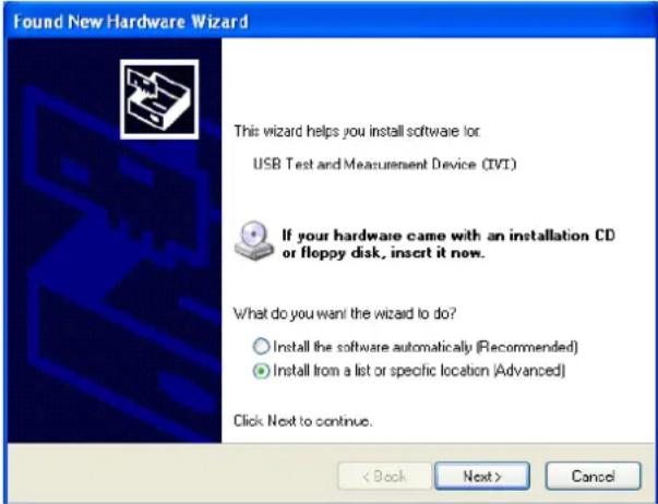
Excel Programming Demo
2 Run the DP800_Demo_Excel.xlsm file. Click File→Options at the upper-left corner of the Excel file to open the interface as shown in the figure below. Click Customize Ribbon at the left, check Developer and click OK. At this point, the Excel menu bar displays the Developer menu.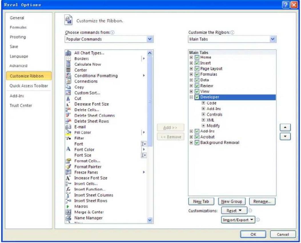
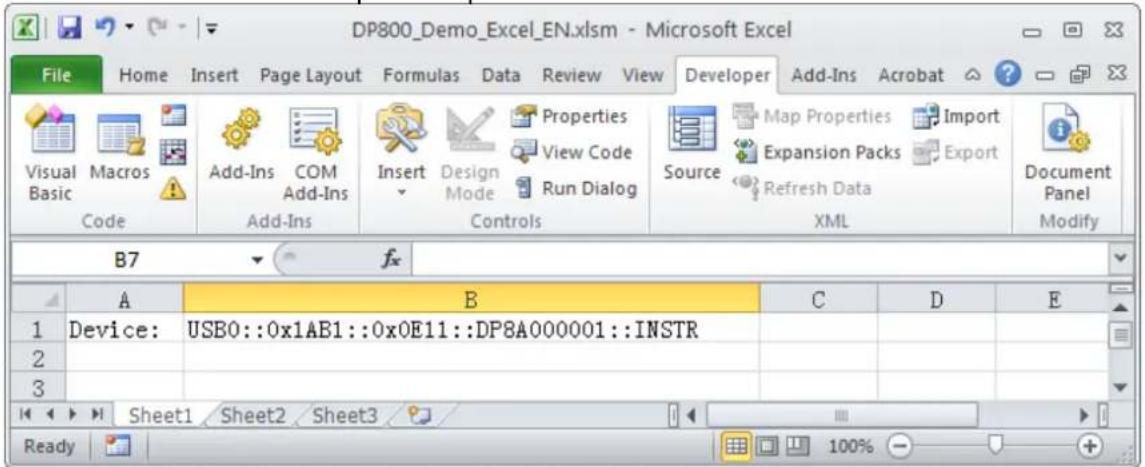

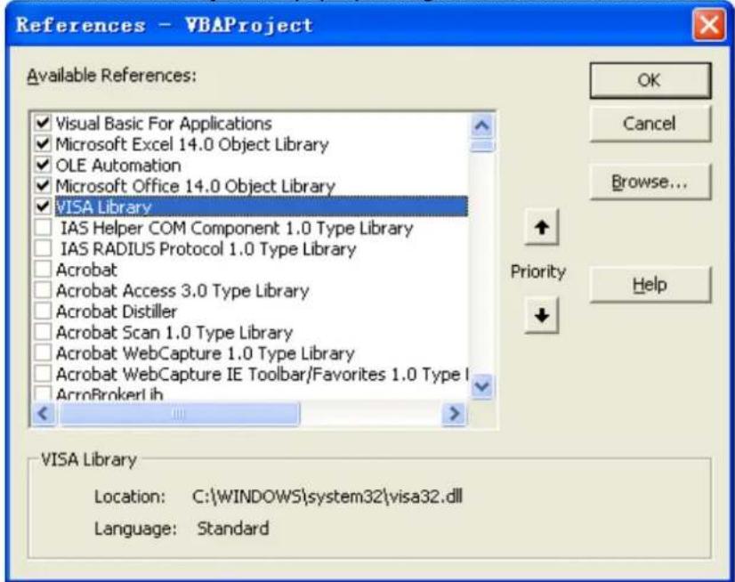
Explanation:
(2) Click Browse... at the right and set the search range to C:\WINDOWS\system32 and the filename to visa32.dll, as shown in the figure below.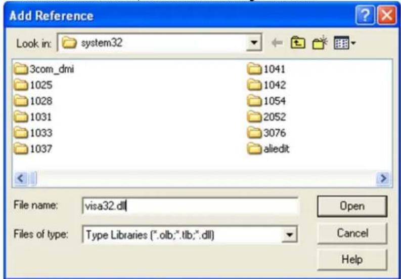
Dim viDefRm As Long
Dim viDevice As Long
Dim viErr As Long
Dim cmdStr As String
Dim idnStr As String * 128
Dim ret As Long
'Turn on the device, the device resource descriptor is in CELLS(1,2) of SHEET1'
viErr = visa.viOpenDefaultRM(viDefRm)
viErr = visa.viOpen(viDefRm, Sheet1.Cells(1, 2), 0, 5000, viDevice)
'Send request, read the data, the return value is in CELLS(2,2) of SHEET1'
cmdStr = "*IDN?"
viErr = visa.viWrite(viDevice, cmdStr, Len(cmdStr), ret)
viErr = visa.viRead(viDevice, idnStr, 128, ret)
Sheet1.Cells(2, 2) = idnStr
'Turn off the device'
visa.viClose (viDevice)
visa.viClose (viDefRm)
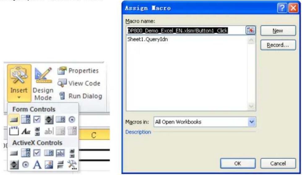
MATLAB Programming Demo

dp800 = visa('ni', 'USB0::0x1AB1::0x0E11::DP8A000001::INSTR'); %Create VISA object
fopen(dp800); %Open the VISA object created
fprintf(dp800, ':MEAS:ALL? CH1'); %Send request
meas_CH1 = fscanf(dp800); %Read data
fclose(dp800); %Close the VISA object
display(meas_CH1) %Display the device information read
meas_CH1 =
1.0259, 0.0416, 0.043
LabVIEW Programming Demo
2 Add controls in the front panel interface, including the Address bar, Command bar and Return bar as well as the Connect, Write, Read and Exit buttons.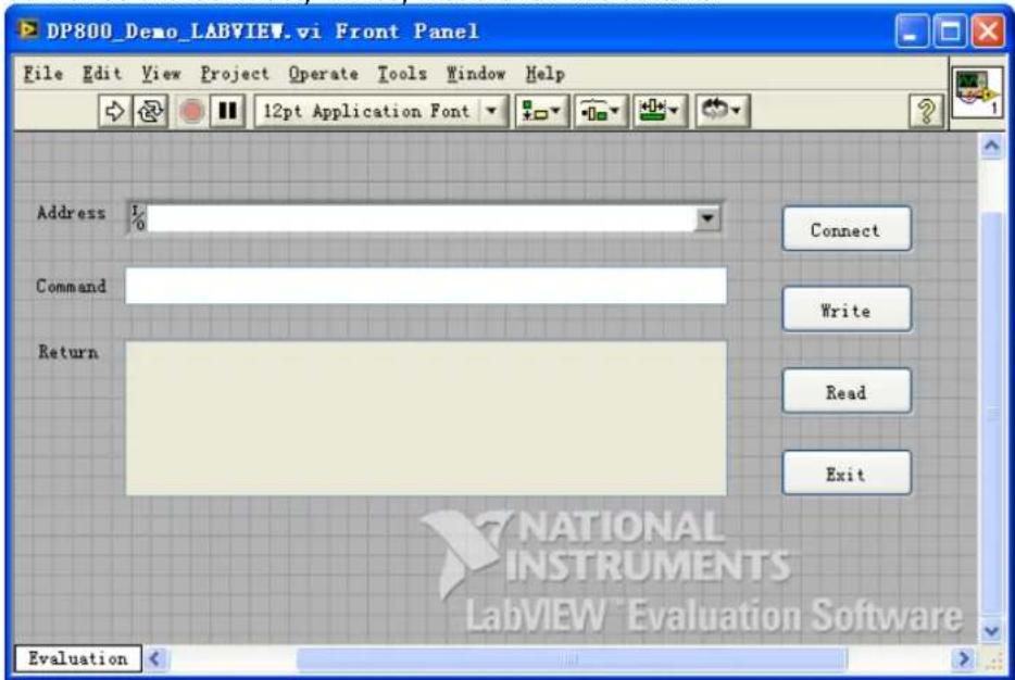
![DP800_Demo_LABVIEW.vi Block Diagram File Edit View Project Operate Tools Window Help 12pt Application Font Address Command Return Connect Write Read Exit I/O abc abc YF YF YF [0] Timeout Type Time Evaluation](/content/2026/05/906356/images/9b15bb7735966b899159af483cbadae67ab19a8db66a4a90614d6e2c6b993af5.jpg)
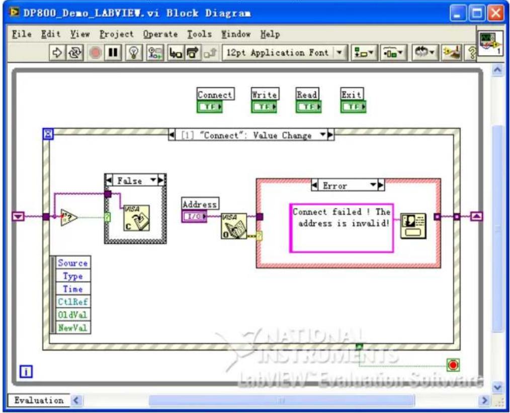
flowchart
graph TD
    A["Source<br>Type<br>Time<br>CtlRef<br>OldVal<br>NewVal"] --> B{False}
    B --> C["VISA C"]
    C --> D["Address I/O"]
    D --> E["VISA 0"]
    E --> F{Connect failed ! The address is invalid!}
    F --> G["Error"]
    G --> H["1"] "Connect": Value Change
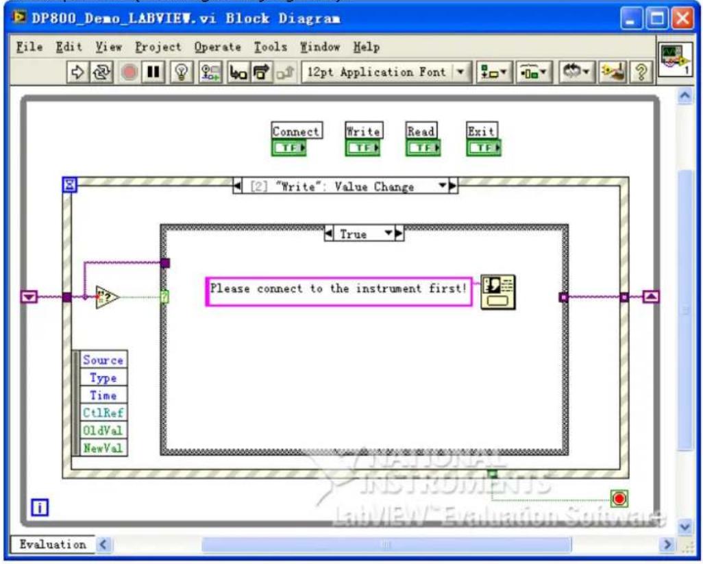
flowchart
graph TD
    A["Source"] --> B["Type"]
    B --> C["Time"]
    C --> D["Ct1Ref"]
    D --> E["OldVal"]
    E --> F["NewVal"]
    G["Connect"] --> H["Write"]
    H --> I["Read"]
    I --> J["Exit"]
    K["True"] --> L["Please connect to the instrument first!"]
    M["2"] --> N[""Write": Value Change"]
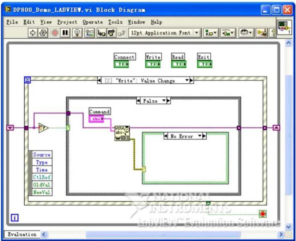
flowchart
graph TD
    A["Source Type"] --> B["Command abc"]
    C["Type Time"] --> B
    D["Ct1Ref OldVal"] --> E["VISA abc"]
    F["OldVal NewVal"] --> G["No Error"]
    B --> H["False"]
    E --> H
    G --> H
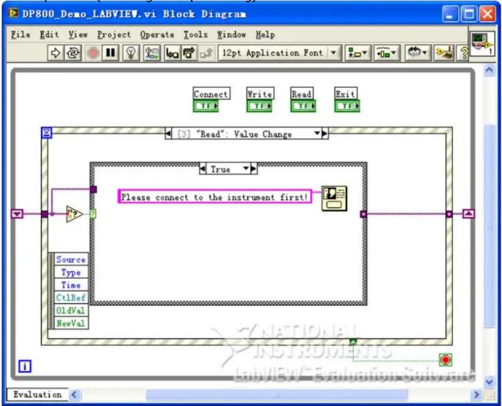
flowchart
graph TD
    A["Source"] --> B["Type"]
    B --> C["Time"]
    C --> D["Ct1Ref"]
    D --> E["OldVal"]
    E --> F["NewVal"]
    G["Connect"] --> H["Write"]
    H --> I["Read"]
    I --> J["Exit"]
    K["12pt Application Font"] --> L["End"]
(4) Exit:
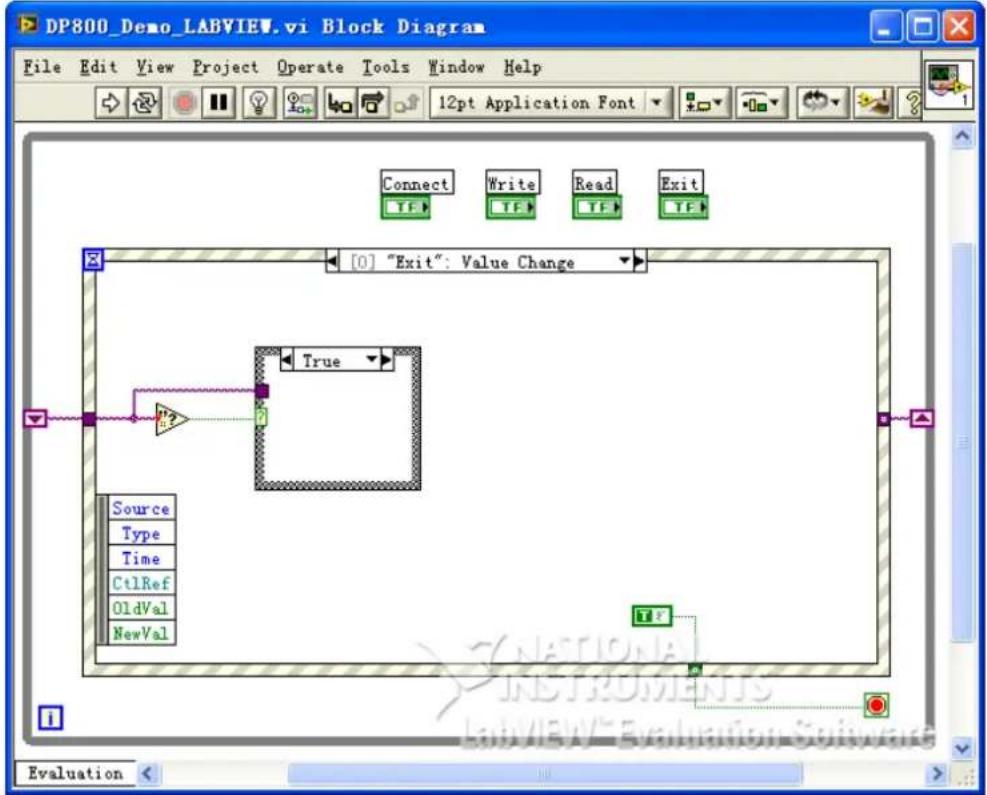
flowchart
graph TD
    A["Source"] --> B{P2}
    B --> C["True"]
    C --> D["End"]
    E["Type"] --> F["End"]
    G["Time"] --> H["End"]
    I["Ct1Ref"] --> J["End"]
    K["OldVal"] --> L["End"]
    M["NewVal"] --> N["End"]
    O["End"] --> P["End"]
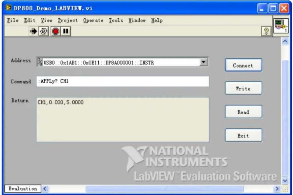
Visual Basic Programming Demo
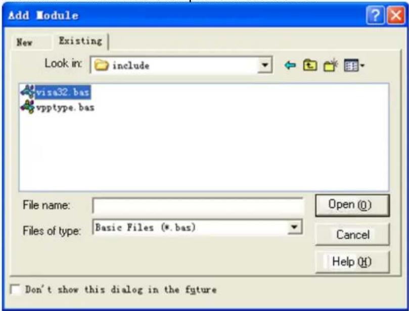
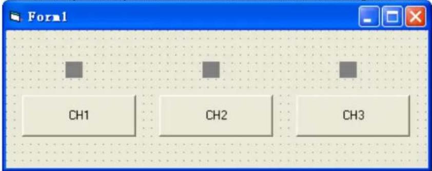
2) Click CH2 to enable CH2 and the control above CH2 turns blue;
3) Click CH3 to enable CH3 and the control above CH3 turns rosy.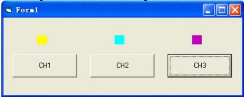
Visual C++ Programming Demo
2 Click Project→Settings and add visa32.lib in the Link tab in the pop-up interface manually.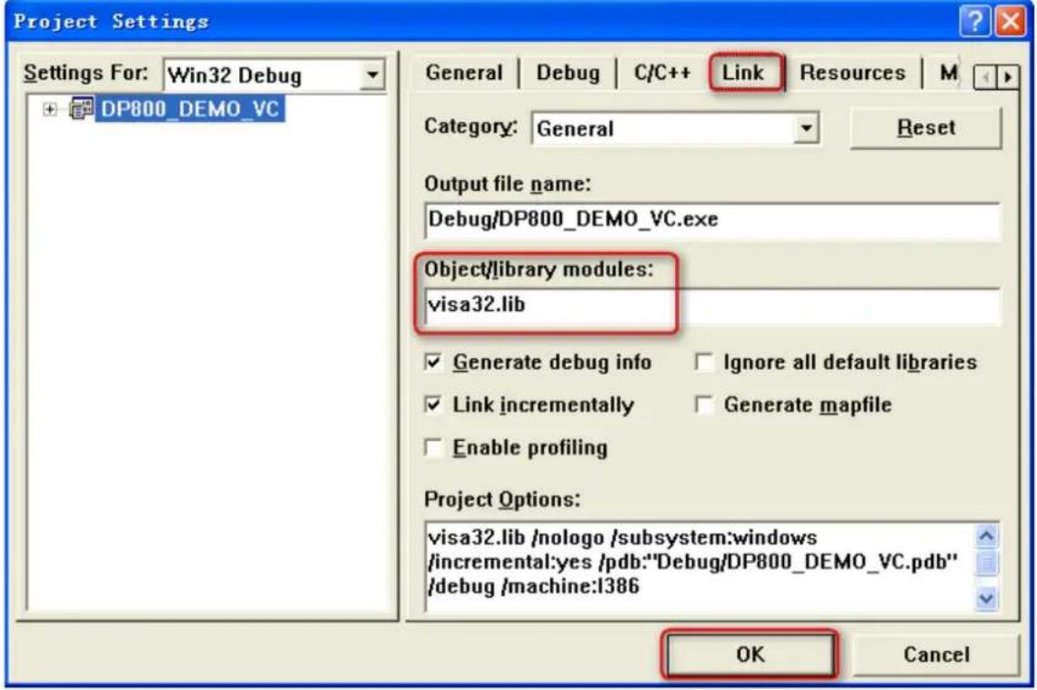
Note:
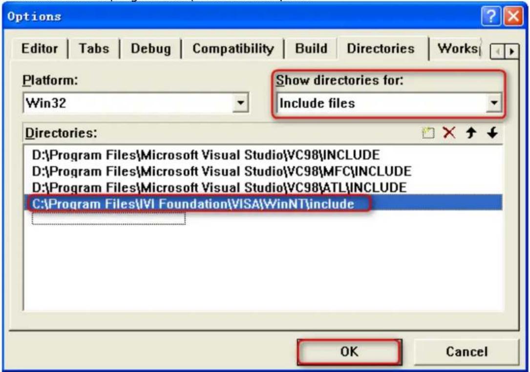
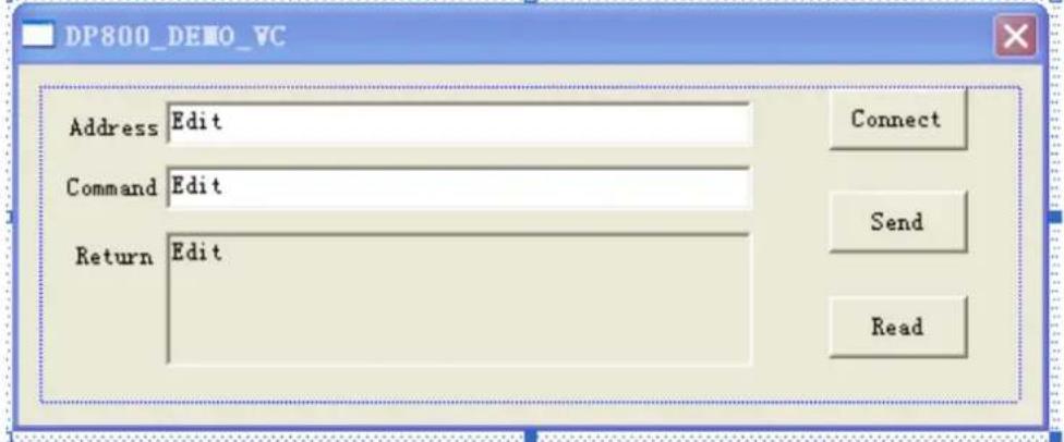
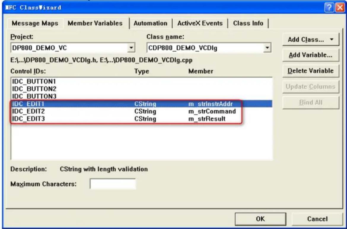
{
    ViSession defaultRM, instr;
    ViStatus status;
    ViUInt32 retCount;
    char * SendBuf = NULL;
    char * SendAddr = NULL;
    bool bWriteOK = false;
    CString str;
SendAddr = strAddr.GetBuffer(strAddr.GetLength());
    strcpy(SendAddr, strAddr);
strAddr.ReleaseBuffer();
SendBuf = strContent.GetBuffer(strContent.GetLength());
strcpy(SendBuf, strContent);
strContent.ReleaseBuffer();
status = viOpenDefaultRM(&defaultRM);
if (status < VI_SUCCESS)
{
    AfxMessageBox("No VISA instrument was opened !");
return false;
}

status = viOpen(defaultRM, SendAddr, VI_NULL, VI_NULL, &instr);
//write command to the instrument
status = viWrite(instr, (unsigned char *)SendBuf, strlen(SendBuf), &retCount);

//close the instrument
status = viClose(instr);
status = viClose(defaultRM);

return bWriteOK;
}

2) Encapsulate the read operation of VISA for easier operation.
bool CDP800_DEMO_VCDlg::InstrRead(CString strAddr, CString *pstrResult)
//Read from the instrument
{
ViSession defaultRM,instr;
ViStatus status;
ViUInt32 retCount;
char * SendAddr = NULL;
unsigned char RecBuf[MAX_REC_SIZE];
bool bReadOK = false;
CString str;

//Change the address's data style from CString to char*
SendAddr = strAddr.GetBuffer(strAddr.GetLength());
strcpy(SendAddr,strAddr);
strAddr.ReleaseBuffer();

memset(RecBuf,0,MAX_REC_SIZE);

//open the VISA instrument
status = viOpenDefaultRM(&defaultRM);
if (status < VI_SUCCESS)
{
    // Error Initializing VISA...exiting
    AfxMessageBox("No VISA instrument was opened !");
    return false;
}

//open the instrument
status = viOpen(defaultRM, SendAddr, VI_NULL, VI_NULL, &instr);

//read from the instrument
status = viRead(instr, RecBuf, MAX_REC_SIZE, &retCount);

//close the instrument
status = viClose(instr);
status = viClose(defaultRM);

(*pstrResult).Format("%s",RecBuf);

return bReadOK;
}
1) Connect the instrument
void CDP800_DEMO_VCDlg::OnConnect()
{
    // TODO: Add your control notification handler code here
ViStatus status;
ViSession defaultRM;
ViString expr = "?*";
ViPFindList findList = new unsigned long;
    ViPUInt32 retcnt = new unsigned long;
ViChar instrDesc[1000];
CString strSrc = "";
CString strInstr = "";
unsigned long i = 0;
bool bFindDP = false;

status = viOpenDefaultRM(&defaultRM);
if (status < VI_SUCCESS)
{
    // Error Initializing VISA...exiting
    MessageBox("No VISA instrument was opened ! ");
    return;
}

memset(instrDesc,0,1000);

// Find resource
status = viFindRsrc(defaultRM,expr,findList, retcnt, instrDesc);

for (i = 0;i < (*retcnt);i++)
{
    // Get instrument name
    strSrc.Format("%s",instrDesc);
    InstrWrite(strSrc,"*IDN?");
    ::Sleep(200);
    InstrRead(strSrc,&strInstr);

    // If the instrument(resource) belongs to the DP series then jump out from the loop
    strInstr.MakeUpper();
    if (strInstr.Find("DP") >= 0)
    {
    bFindDP = true;
    m_strInstrAddr = strSrc;
    break;
    }

    // Find next instrument
    status = viFindNext(*findList,instrDesc);
}

if (bFindDP == false)
{
    MessageBox("Didn't find any DP!");
}
UpdateData(false);
}
2) Write operation
void CDP800_DEMO_VCDlg::OnSend()
{
    // TODO: Add your control notification handler code here
UpdateData(true);
if (m_strInstrAddr.IsEmpty())
{
    MessageBox("Please connect to the instrument first!");
}
InstrWrite(m_strInstrAddr, m_strCommand);
m_strResult.Empty();
UpdateData(false);
}

3) Read operation
void CDP800_DEMO_VCDlg::OnRead()
{
    // TODO: Add your control notification handler code here
UpdateData(true);
InstrRead(m_strInstrAddr, &m_strResult);
UpdateData(false);
}
2) Enter the command in to the Command textbox, for example, :APPLy? CH1;
3) Click Send to send the command;
4) Click Read to read the return value.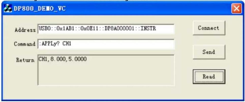
Chapter 5 Appendix
Appendix A: Command List
:ANALyzer:ANALyze
:ANALyzer:CURRTime
:ANALyzer:ENDTime
:ANALyzer:FILE?
:ANALyzer:MEMory
:ANALyzer:MMEMory
:ANALyzer:OBJECT
:ANALyzer:RESult?
:ANALyzer:STARTTime
:ANALyzer:VALue?
:APPLy
*RST
*SAV
*SRE
*STB?
*TRG
*TST?
*WAI
◆ :INSTrument Commands
:INSTrument:COUPle[:TRIGger]
:INSTrument:NSELECT
:INSTrument[:SELECT]
:INSTrument[:SELECT]:MONItor:POWER:CONDITION
:MONItor:POWER[:VALue]
:MONItor[:STATE]
:MONItor:STOPway
:MONItor:VOLTage:CONDITION
:MONItor:VOLTage[:VALue]
◆ :OUTPUT Commands
:OUTPUT:CVCC?
:OUTPUT:MODE?
:OUTPUT:OCP:ALAR?
:OUTPUT:OCP:QUES?
:OUTPUT:OCP:CLEAR
:OUTPUT:OCP[:STATE]
:OUTPUT:OCP:VALue
:OUTPUT:OVP:ALAR?
:OUTPUT:OVP:QUES?
:OUTPUT:OVP:CLEAR
:OUTPUT:OVP[:STATE]
:OUTPUT:OVP:VALue
:OUTPUT:RANGE
:OUTPUT:SENSe
:OUTPUT[:STATE]
:OUTPUT:TIMEr
:OUTPUT:TIMEr:STATE
:OUTPUT:TRACK
◆ :PRESet Commands
:PRESet[:APPLY]
:PRESet:KEY
:PRESet:USER[<n>]:SET:CURRENT
:PRESet:USER[<n>]:SET:DEFault
:PRESet:USER[<n>]:SET:OCP
:PRESet:USER[<n>]:SET:OTP
:PRESet:USER[<n>]:SET:OVP
:PRESet:USER[<n>]:SET:SURE
:PRESet:USER[<n>]:SET:TRACK
:PRESet:USER[<n>]:SET:VOLTage
◆ :RECALL Commands
:RECALL:LOCaI
:RECAII:EXTERnal
◆ :SOURce Commands
[:SOURce[
:SYSTem:COMMunicate:LAN:AUTOip[:STATE]
:SYSTem:COMMunicate:LAN:DHCP[:S TATe]
:SYSTem:COMMunicate:LAN:DNS
:SYSTem:COMMunicate:LAN:GATEway
:SYSTem:COMMunicate:LAN:IPADdress
:SYSTem:COMMunicate:LAN:MAC?
:SYSTem:COMMunicate:LAN:MANualip[:STATE]
:SYSTem:COMMunicate:LAN:SMASK
:SYSTem:COMMunicate:RS232:BAUD
:SYSTem:COMMunicate:RS232:DATABit
:SYSTem:COMMunicate:RS232:FLOWCrl
:SYSTem:COMMunicate:RS232:PARItybit
:SYSTem:COMMunicate:RS232:STOPBit
:SYSTem:CONTrast
:SYSTem:ERRor?
:SYSTem:KLOCk
:SYSTem:KLOCk:STATE
:SYSTem:LANGUAGE:TYPE
:SYSTem:LOCal
:SYSTem:LOCK
:SYSTem:ONOFFSync
:SYSTem:OTP
:SYSTem:POWEron
:SYSTem:REMOTE
:SYSTem:RGBBrightness
:SYSTem:RWLock
:SYSTem:SAVer
:SYSTem:SELF:TEST:BOARD?
:SYSTem:SELF:TEST:FAN?
:SYSTem:SELF:TEST:TEMP?
:SYSTem:TRACKMode
:SYSTem:VERSION?Appendix B: Factory Setting
DP831A Voltage/Current Setting Values CH1: 0.000V/5.0000ACH2: 00.000V/2.0000ACH3: -00.000V/2.0000A Voltage/Current Limits CH1: 8.800V/5.5000ACH2: 33.000V/2.2000ACH3: -33.000V/2.2000A OVP/OCP On/Off CH1/CH2/CH3: Off/Off Output On/Off CH1/CH2/CH3: Off Track On/Off CH1: NoneCH2/CH3: Off Current Channel CH1 DP832A Voltage/Current Setting Values CH1: 00.000V/3.000ACH2: 00.000V/3.000ACH3: 0.000V/3.000A Voltage/Current Limits CH1: 33.000V/3.300ACH2: 33.000V/3.300ACH3: 5.500V/3.300A OVP/OCP On/Off CH1/CH2/CH3: Off/Off Output On/Off CH1/CH2/CH3: Off Track On/Off CH1/CH2: OffCH3: None Current Channel CH1 DP821A Voltage/Current Setting Values CH1: 00.000V/1.0000ACH2: 0.000V/10.000A Voltage/Current Limits CH1: 66.000V/1.1000ACH2: 8.800V/11.000A OVP/OCP On/Off CH1/CH2: Off/Off Output On/Off CH1/CH2: Off Sense On/Off CH1: NoneCH2: Off Current Channel CH1 DP822A Voltage/Current Setting Values CH1: 00.000V/5.000ACH2: 0.000V/16.000A Voltage/Current Limits CH1: 22.000V/5.500ACH2: 5.500V/16.800A OVP/OCP On/Off CH1/CH2: Off/Off Output On/Off CH1/CH2: Off Sense On/Off CH1: NoneCH2: Off Current Channel CH1 DP811A Voltage/Current Setting Values 00.000V/05.0000A Voltage/Current Limits 22.000V/11.0000A OVP/OCP On/Off Off/Off Output On/Off Off Sense On/Off Off Current Range Range1 DP813A Voltage/Current Setting Values 00.000V/20.000A Voltage/Current Limits 8.800V/22.000A OVP/OCP On/Off Off/Off Output On/Off Off Sense On/Off Off Current Range Range1 DP831^[1] Voltage/Current Setting Values CH1: 0.000V/5.000ACH2: 00.00V/2.000ACH3: -00.00V/2.000A Voltage/Current Limits CH1: 8.800V/5.500ACH2: 33.00V/2.200ACH3: -33.00V/2.200A OVP/OCP On/Off CH1/CH2/CH3: Off/Off Output On/Off CH1/CH2/CH3: Off Track On/Off CH1: NoneCH2/CH3: Off Current Channel CH1 DP832^[1] Voltage/Current Setting Values CH1: 00.00V/3.000ACH2: 00.00V/3.000ACH3: 0.00V/3.000A Voltage/Current Limits CH1: 33.00V/3.300ACH2: 33.00V/3.300ACH3: 5.50V/3.300A OVP/OCP On/Off CH1/CH2/CH3: Off/Off Output On/Off CH1/CH2/CH3: Off Track On/Off CH1/CH2: OffCH3: None Current Channel CH1 DP822^[1] Voltage/Current Setting Values CH1: 00.00V/5.000ACH2: 0.00V/16.00A Voltage/Current Limits CH1: 22.00V/5.500ACH2: 5.50V/16.80A OVP/OCP On/Off CH1/CH2: Off/Off Output On/Off CH1/CH2: Off Sense On/Off CH1: NoneCH2: Off Current Channel CH1 DP821^[1] Voltage/Current Setting Values CH1: 00.00V/1.000ACH2: 0.00V/10.00A Voltage/Current Limits CH1: 66.00V/1.100ACH2: 8.80V/11.00A OVP/OCP On/Off CH1/CH2: Off/Off Output On/Off CH1/CH2: Off Sense On/Off CH1: NoneCH2: Off Current Channel CH1 DP811^[1] Voltage/Current Setting Values 00.00V/05.00A Voltage/Current Limits 22.00V/11.00A OVP/OCP On/Off Off/Off Output On/Off Off Sense On/Off Off DP813[1] Voltage/Current Setting Values 00.00V/20.00A Voltage/Current Limits 8.80V/22.00A OVP/OCP On/Off Off/Off Output On/Off Off Sense On/Off Off Current Range Range1 Display* Luminance 50% Contrast 25% RGB Brightness 50% Display Mode Normal Display Theme[2] Green System Setting Language* Chinese Power-on Setting* Default Print Destination USB Disk Print Copies 1 Print Format BMP Print Invert Yes Print Color Grayscale OTP On Beeper On Screen Saver Off Keyboard Lock Password* Off Track Mode Synchronous On/Off Sync Disable Preset Key Default I/O Setting* GPIB Address 2 RS232 Baud Rate 9600 Data Bit 8 Stop Bit 1 Parity Bit None Hardware Flow Control Off LAN DHCP On Auto IP On Manual IP Off Timer Channel CH1 Timer On/Off Off Output Groups 1 Timer Parameters Volt: 1V; Curr: 1A; Set: 1s Cycles 1 End State Output Off Templet Sine Object Voltage Current 0A Max Value 1V Min Value 0V Points 10 Interval 1s Inverted Off Channel CH1 Delayer On/off Off Output Groups 1 Delayer Parameter State: Off, On alternately Cycles 1 End State Output Off State Generation 0 1Patt Time Generation FixTime FixTime On Delay: 1s; Off Delay: 1s Increase/Decline Base Value: 1s; Step: 1s Stop Condition None Recorder Switch Off Record Period 1s Destination C:\REC 10:RIGOL.ROF Channel Number CH1 Analysis Object Voltage Display Curve Current Time 1s Start Time 1s End Time 2s Group 0 Median 0V Mode 0V Average 0V Variance 0V Range 0V Min Value 0V Max Value 0V Mead Deviation 0V Monitor Channel CH1 Monitor Switch Off Monitor Condition >Volt Voltage Half of the rated value of CH1 (for DP811A/DP811, it is half of the rated value of Range 1) Current Half of the rated value of CH1 (for DP811A/DP811, it is half of the rated value of Range 1) Power The product of voltage times current Stop Mode Output Off, Warning, Beeper Trigger Direction In Trigger Input Data Line D0 Source under Control CH1 Trigger Type RiseEdge Output Response Output Off Sensitivity Low Enable No Trigger Output Data Line D0 Control Source CH1 Trigger Condition Output Off Output Signal Level Square Period: 1s; Duty: 50% Polarity Positive Enable No Store Browser Directory Directory C:/ File The first file File Type *.rsf Appendix C: Warranty
- DP800 Series Programmable Linear DC Power Supply
- Guaranty and Declaration
- Copyright
- Trademark Information
- Publication Number
- Software Version
- Notices
- Product Certification
- Contact Us
- Document Overview
- Main Topics in this Manual:
- Chapter 1 Programming Overview
- Chapter 2 Command System
- Chapter 3 Application Examples
- Chapter 4 Programming Demos
- Chapter 5 Appendix
- Tip
- Format Conventions in this Manual:
- Key
- Menu
- Operation Step
- Content Conventions in this Manual:
- Contents
- Guaranty and Declaration.... I
- Document Overview ......II
- Chapter 1 Programming Overview ......1-1
- Chapter 2 Command System 2-1
- Chapter 3 Application Examples....3-1
- Chapter 4 Programming Demos 4-1
- Chapter 5 Appendix....5-1
- Main topics of this chapter:
- To Build Remote Communication
- Operation Steps:
- Install the Ultra Sigma common PC software
- Check whether the connection is successful
- Remote Control Methods
- User-defined Programming
- Send SCPI Commands via the PC Software
- SCPI Command Overview
- Syntax
- Symbol Description
- Braces {}
- Vertical Bar |
- Square Brackets [ ]
- Triangle Brackets < >
- Parameter Type
- Bool
- Integer
- Real Number
- Discrete
- ASCII String
- Command Abbreviation
- SCPI Status Registers
- Event Register
- Enable Register
- Multi-logic Output
- Questionable Status Register
- Questionable Status Register of Multi-channel Models
- Channel Questionable Status Register
- Channel Questionable Status SUMMARY Register
- Questionable Status Register of Single-channel Model
- Standard Event Register
- :ANALyzer Commands
- Command List [1] :
- :ANALyzer:ANALyze
- :ANALyzer:CURRTime
- :ANALyzer:ENDTime
- Explanation
- Commands
- :ANALyzer:FILE?
- :ANALyzer:MEMory
- :ANALyzer:MMEMory
- :ANALyzer:OBJECT
- :ANALyzer:RESult?
- :ANALyzer:STARTTime
- :ANALyzer:VALue?
- :APPLy Command
- :APPLY
- Description
- Parameter
- Return Format
- :DELAY Commands
- Command List:
- :DELAY:CYCLEs
- :DELAY:ENDState
- :DELAY:GROUPs
- Example
- Related
- :DELAY:PARAMeter
- :DELAY[:STATE]
- :DELAY:STATE:GEN
- :DELAY:STOP
- :DELAY:TIME:GEN
- :DISPLAY Commands
- :DISPLAY:MODE
- :DISPLAY[:WINDOW][:STATE]
- :DISPLAY[:WINDOW]:TEXT:CLEar
- Command
- :DISPLAY[:WINDOW]:TEXT[:DATA]
- IEEE488.2 Common Commands
- \*CLS
- \*ESE
- \*ESR?
- Related Command
- \*IDN?
- \*OPC
- \*OPT?
- \*PSC
- \*RCL
- \*RST
- \*SAV
- \*TRG
- Syntax \*TRG
- \*TST?
- Syntax \*TST?
- \*WAI
- Syntax \*WAI
- :INITiate Command
- :INITiate
- :INSTrument Commands
- :INSTrument:COUPle[:TRIGger]
- :INSTrument:NSELect
- :INSTrument[:SELEct]
- :LIC Command
- :LIC:SET
- :MEASure Commands
- :MEASure:ALL[:DC]?
- :MEASure[:VOLTage][:DC]?
- :MEMory Commands
- :MEMory[:STATe]:DElete
- :MMEMory Commands
- :MMEMory:CATalog?
- :MMEMory:CDIRectory
- Related Commands
- :MMEMory:DElete
- :MMEMory:DISK?
- :MMEMory:LOAD
- :MMEMory:MDIRectory
- :MMEMory:STORe
- :MONItor Commands
- :MONItor:CURRENT:CONDITION
- :MONItor:POWER[:VALue]
- :MONItor[:STATE]
- :MONItor:STOPway
- :MONItor:VOLTage:CONDITION
- :MONItor:VOLTage[:VALue]
- :OUTPUT Commands
- :OUTPUT:CVCC?
- :OUTPUT:MODE?
- :OUTPUT:OCP:ALAR?
- :OUTPUT:OCP:QUES?
- :OUTPUT:OCP:CLEAR
- :OUTPUT:OCP[:STATE]
- :OUTPUT:OCP:VALue
- :OUTPUT:OVP:ALAR?
- :OUTPUT:OVP:QUES?
- :OUTPUT:OVP:CLEAR
- :OUTPUT:OVP[:STATE]
- :OUTPUT:OVP:VALue
- :OUTPUT:RANGE
- :OUTPUT:SENSe
- :OUTPUT[:STATE]
- :OUTPUT:TIMEr
- :OUTPUT:TIMEr:STATE
- :OUTPUT:TRACK
- :PRESet Commands
- :PRESet[:APPLY]
- :PRESet:KEY
- :PRESet:USER[]:SET:CURRENT
- :PRESet:USER[]:SET:DEFault
- :PRESet:USER[]:SET:OCP
- :PRESet:USER[]:SET:OTP
- :PRESet:USER[]:SET:OVP
- :PRESet:USER[]:SET:SURE
- :PRESet:USER[]:SET:TRACK
- :PRESet:USER[]:SET:VOLTage
- :RECAII Commands
- :RECAII:LOCal
- :RECAII:EXTErnal
- :REBorder Commands
- :REBorder:DESTination?
- :REBorder:MEMory
- :REBorder:MMEMory
- :REBorder:PERIOD
- :REBorder[:STATe]
- :SOURce Commands
- [:SOURCE[]]:CURRENT[:LEVel][:IMmediate][:AMPLitude]
- [:SOURCE[]]:CURRENT[:LEVel][:IMmediate]:STEP[:INCRement]
- [:SOURce[]]:CURRENT[:LEVel]:TRIGgered[:AMPLitude]
- Format
- [:SOURCE[]]:CURRENT:PROTection:CLEar
- [:SOURCE[]]:CURRENT:PROTection[:LEVel]
- [:SOURCE[]]:CURRENT:PROTection:STATE
- [:SOURCE[]]:CURRENT:PROTection:TRIPped?
- [:SOURce[]]:VOLTage[:LEVel][:IMMediate][:AMPLitude]
- [:SOURCE[]]:VOLTage[:LEVel][:IMMediate]:STEP[:INCRement]
- [:SOURce[]]:VOLTage[:LEVel]:TRIGgered[:AMPLitude]
- [:SOURCE[]]:VOLTage:PROTection:CLEar
- [:SOURCE[]]:VOLTage:PROTection[:LEVel]
- [:SOURCE[]]:VOLTage:PROTection:STATE
- [:SOURCE[]]:VOLTage:PROTection:TRIPped?
- [:SOURCE[]]:VOLTage:RANGE
- :STATus Commands
- :STATUS:QUESTIONable:CONDITION?
- :STATus:QUESTIONable:ENABLE
- :STATus:QUESTIONable[:EVENT]?
- :STATus:QUESTIONable:INSTrument:ENABLE
- :STATus:QUESTIONable:INSTrument[:EVENT]?
- :STATUS:QUESTIONable:INSTRument:ISUMmary[]:COND?
- :STATus:QUESTIONable:INSTRument:ISUMmary[]:ENABLE
- :STATUS:QUESTIONable:INSTRument:ISUMmary[][:EVENT]?
- :STORe Commands
- :STORe:LOCal
- :STORe:EXTErnal
- :SYSTem Commands
- :SYSTem:BEEPer:IMMediate
- :SYSTem:BRIGHTness
- :SYSTem:COMMunicate:GPIB:ADDRess
- :SYSTem:COMMunicate:LAN:APPLy
- :SYSTem:COMMunicate:LAN:AUTOip[:STATe]
- :SYSTem:COMMunicate:LAN:DNS
- :SYSTem:COMMunicate:LAN:GATEway
- :SYSTem:COMMunicate:LAN:IPADdress
- :SYSTem:COMMunicate:LAN:MAC?
- :SYSTem:COMMunicate:LAN:MANualip[:STATe]
- :SYSTem:COMMunicate:LAN:SMASK
- :SYSTem:COMMunicate:RS232:BAUD
- :SYSTem:COMMunicate:RS232:DATABit
- :SYSTem:COMMunicate:RS232:FLOWCrl
- :SYSTem:COMMunicate:RS232:PARItybit
- :SYSTem:COMMunicate:RS232:STOPBit
- :SYSTem:CONTrast
- :SYSTem:ERRor?
- :SYSTem:KLOCk
- :SYSTem:KLOCk:STATe
- :SYSTem:LOCal
- :SYSTem:LOCK
- :SYSTem:ONOFFSync
- :SYSTem:OTP
- :SYSTem:POWEron
- :SYSTem:RENote
- :SYSTem:RGBBrightness
- :SYSTem:RWLock
- :SYSTem:SAVer
- :SYSTem:TRACKMode
- :SYSTem:VERSION?
- :TIMEr Commands
- :TIMEr:CYCLEs
- :TIMEr:ENDState
- :TIMEr:GROUPs
- :TIMEr:PARAMeter
- Related :OUTPut:TIMEr Command
- :TIMEr[:STATe]
- :TIMER:TEMPlet:CONSTruct
- :TIMEr:TEMPlet:FALLRate
- :TIMEr:TEMPlet:INTERval
- :TIMEr:TEMPlet:INVErt
- :TIMEr:TEMPlet:MAXValue
- :TIMEr:TEMPlet:MINValue
- :TIMEr:TEMPlet:OBJECT
- :TIMEr:TEMPlet:PERIOD
- :TIMEr:TEMPlet:POINTS
- :TIMEr:TEMPlet:RISERate
- :TIMEr:TEMPlet:SELECT
- :TIMEr:TEMPlet:SYMMetry
- :TIMEr:TEMPlet:WIDTH
- :TRIGger Commands
- :TRIGger:IN:CHTYpe
- :TRIGger:IN:CURRENT
- :TRIGger:IN[:ENABLE]
- :TRIGger:IN:IMMEdiate
- :TRIGger:IN:RESPONSE
- :TRIGger:IN:SENSitivity
- :TRIGger:IN:SOURce
- :TRIGger:IN:TYPE
- :TRIGger:IN:VOLTage
- :TRIGger:OUT:CONDITION
- :TRIGger:OUT:DUTY
- :TRIGger:OUT[:ENABLE]
- :TRIGger:OUT:PERIod
- :TRIGger:OUT:POLArity
- :TRIGger:OUT:SIGNal
- :TRIGger:OUT:SOURce
- :TRIGger[:SEQUence]:DELay
- :TRIGger[:SEQUence]:SOURce
- Note:
- CV Output
- Requirement
- Track Function
- Timing Output
- Delay Output
- To Trigger the Power Supply
- To Use the Recorder
- To Use the Analyzer
- To Use the Monitor
- To Use the Trigger
- Trigger Input
- Trigger Output
- Programming Preparations
- Excel Programming Demo
- Explanation:
- MATLAB Programming Demo
- LabVIEW Programming Demo
- Exit:
- Visual Basic Programming Demo
- Visual C++ Programming Demo
- Appendix A: Command List
- Appendix B: Factory Setting
- Appendix C: Warranty
Brand : Rigol
Model : DP813A
Category : Measurement