
Omnipressor 2830Au - Compressor EVENTIDE - Free user manual and instructions
Find the device manual for free Omnipressor 2830Au EVENTIDE in PDF.


| Product Type | Compressor/Limiter/Expander |
| Brand | Eventide |
| Model | Omnipressor 2830Au |
| Form Factor | 2U Rackmount |
| Dimensions (Width x Height x Depth) | 19 x 3.5 x 8.5 inches (483 x 89 x 216 mm) |
| Weight | 12 lbs (5.4 kg) |
| Power Supply | 100-240 VAC, 50/60 Hz, 30W |
| Audio Inputs | Balanced XLR and 1/4" TRS |
| Audio Outputs | Balanced XLR and 1/4" TRS |
| Controls | Threshold, Ratio, Attack, Release, Gain, Omnipressor Mode, Bypass |
| Modes | Compression, Limiting, Expansion, Omnipressor (dynamic reversal) |
| Metering | VU meter for gain reduction and output level |
| Frequency Response | 20 Hz - 20 kHz ±0.5 dB |
| Maximum Input Level | +20 dBu |
| Maximum Output Level | +20 dBu |
| Signal to Noise Ratio | >100 dB |
| THD+N | <0.05% typical |
| Safety | Use grounded outlets; avoid liquids; unplug during storms |
| Maintenance & Cleaning | Wipe with dry cloth; avoid solvents |
| Spare Parts & Repairability | Contact Eventide support or authorized service centers |
Frequently Asked Questions - Omnipressor 2830Au EVENTIDE
User questions about Omnipressor 2830Au EVENTIDE
0 question about this device. Answer the ones you know or ask your own.
Ask a new question about this device
Download the instructions for your Compressor in PDF format for free! Find your manual Omnipressor 2830Au - EVENTIDE and take your electronic device back in hand. On this page are published all the documents necessary for the use of your device. Omnipressor 2830Au by EVENTIDE.
USER MANUAL Omnipressor 2830Au EVENTIDE
Omnipressor Model 2830*Au User Manual
Version 1.0.0
P/N: 141392 Rev A
This User Manual is an updated version of the original Omnipressor instruction manual from 1974. Like the unit itself, the manual remains true to the original intent and application. References to tape machines, phone lines, etc. appear throughout.
Eventide is a registered trademark of Eventide Inc.
Omnipressor ^® is a registered trademark of Eventide Inc.
© 2023 Eventide Inc. All rights reserved.
OMNIPRESSOR MODEL 2830\*Au
TABLE OF CONTENTS
SECTION 1 INTRODUCTION
General Description 1
Specifications 2
SECTION 2 CONNECTION AND OPERATION
Connection Instructions 3
Control and Indicator Description 4
Linking 7
Applications---Introduction 8
Application Notes
- "Your Backwards Omnipressor" 10
- Standard Operating Modes 12
- Voltage Controlled Amplifier 13
- Predictive Compression 14
- Omnipressor As A Noise Reduction Unit 15
SECTION 3 TECHNICAL DATA
Block Diagram 17
Theory of Operation 18
GENERAL DESCRIPTION

The 50th anniversary Model 2830*Au Omnipressor® is a professional-quality dynamic modifier, combining the characteristics of a compressor, expander, noise gate, and limiter in one convenient package. Its dynamic reversal feature makes high-level input signals lower than corresponding low-level inputs. Musically, this reverses the attack-decay envelope of plucked strings, drums, and similar instruments and gives the effect of “talking backward” when applied to a voice signal. When a return to normalcy is desired, the LINE switch is used to bypass the Omnipressor.
The Omnipressor provides an unusually wide range of controls, useful in all program-controlled gain changes. The continuously variable Expansion/Compression control goes from an expansion range of 10 to 1 (gate) to a compression range of -10:1 (abrupt reversal); attenuation and gain limit controls adjust the gain control range from a full 60dB to as little as plus and minus 1dB; and variable time constant controls adjust attack/decay times over an approximate 1000 to 1 ratio. The unit's bass-cut switch limits low-frequency response in the level detector.
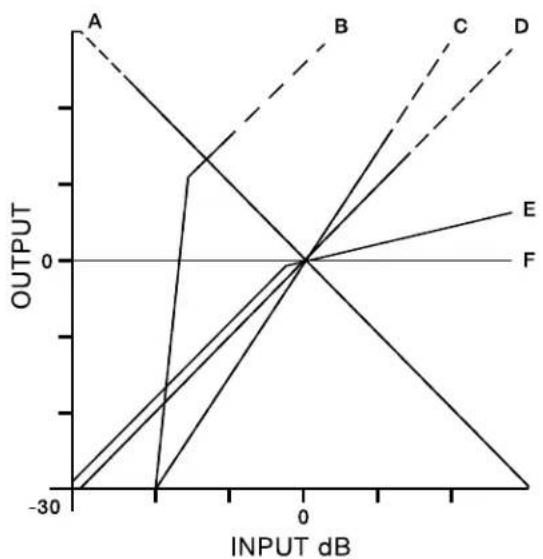
The Omnipressor's unique metering system employs a logarithmic amplifier to generate information on Input, Output, and Gain. Some of the unusual capabilities of the unit are illustrated on the graph below.
OMNIPRESSOR CAPABILITIES
line
| INPUT dB | OUTPUT (A) | OUTPUT (B) | OUTPUT (C) | OUTPUT (D) | OUTPUT (E) | | -------- | ---------- | ---------- | ---------- | ---------- | ---------- | | -30 | 100 | 0 | 0 | 0 | -30 | | -20 | 50 | 100 | 0 | 0 | -20 | | -10 | 20 | 200 | 100 | 0 | -10 | | 0 | 0 | 300 | 200 | 100 | 0 | | 10 | -10 | 400 | 300 | 200 | 10 | | 20 | -20 | 500 | 400 | 300 | 20 | | 30 | -30 | 600 | 500 | 400 | 30 |A: DYNAMIC REVERSAL An input level of +10 results in an output of -10. An input level of -10 results in an output of +10.
B: GATE As the signal decreases below +10, the device gain rapidly goes to minimum.
C: EXPANSION A 40dB input range results in a 60dB output range.
D: CONTROL CENTERED Input level equals output level.
E: LIMITING Gain is unity until input is 0dB. Above 0dB. A 30dB change in input produces a 6dB output change. (Line is offset for clarity.)
F: INFINITE COMPRESSION Output level remains unchanged regardless of input level.
SPECIFICATIONS
| INPUT LEVEL | 0 to +8dB nominal level. Threshold control provided to center gain control operation over range of -25 to +15dB. Maximum level should not exceed +20dB or clipping will occur. |
| INPUT IMPEDANCE | 600 ohm audio transformer. |
| OUTPUT LEVEL | 0 to +8dB nominal level. Maximum level before clipping is +18dB. Output level control may be used to compensate for extremes of gain reduction. |
| OUTPUT IMPEDANCE | 600 ohm audio transformer. |
| FREQUENCY RESPONSE | +0, - 12 dB 20Hz-16kHz; +0, -1dB 15Hz-20kHz. |
| GAIN | AGC disabled: Unity, -12dB to +12dB depending upon OUTPUT level. |
| COMPRESSION | Continuously variable from 1:1 through through -10:1. |
| EXPANSION | Continuously variable from 1:1 through 10:1. |
| GAIN LINEARITY | Infinite compression setting gives constant output level ± 1dB for 60dB change in input level. |
| FUNCTION CONTROL | Continuously variable function knob is used to set appropriate compression/expansion ratio. Control operates parabolically to give spread near center. Common settings are calibrated. |
| LIMIT CONTROLS | The ATTEN LIMIT and GAIN LIMIT controls serve to restrict the gain control range to any value between 0 and 30dB in each direction. |
| DISTORTION | AGC DISABLED: .05% between 20Hz and 20kHz. Typ. .02% at 1kHz. -20dB AGC, +20dB output gain: Less than 1% above 100Hz, .5% at 1kHz. |
| SIGNAL/NOISE | At unity gain, output noise level is below -90dB. |
| METERING | Front panel meter provided which measures either absolute input level, absolute output level, or gain on linear/log scale over 60dB. |
| TIME CONSTANT | DEFINITION: Numbers refer to the time required for the Omni-pressor to change gain by 10dB in response to an input step change of 10dB in infinite compression mode. ATTACK TIME: Continuously variable from 100μs through 100ms. RELEASE TIME: Continuously variable from 1ms through 1 second. |
| POWER REQUIRED | 115V AC, 50-60 Hz ± 12% or 230V AC, 50-60Hz ± 12%; nominal 10 watts. |
| DIMENSIONS | 19in (48.26cm) wide; 3.5in (8.89cm) high; 9in (22.86cm) deep. |
OMNIPRESSOR INTERFACE
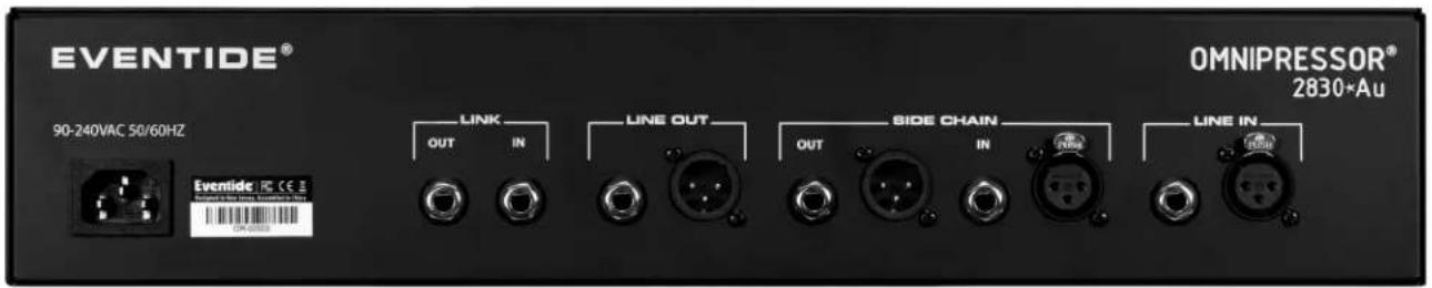
The Omnipressor line inputs and outputs are transformer balanced, while the side chain I/O is active balanced or unbalanced.
LINE IN Transformer isolated, balanced or unbalanced +4dBu line input. Accepts XLR or TRS connection (only one should be connected).
LINE OUT Transformer isolated, balanced or unbalanced +4dBu line output. Accepts XLR or TRS connection (only one should be connected).
SIDE CHAIN IN/OUT Active balanced/unbalanced +4dBu side chain input and output on XLR or TRS connectors (only one should be connected).
LINK IN/OUT Link multiple units in stereo or multi-mono setup using standard TS or TRS patch cables. (See Linking section.)
CONTROL AND INDICATOR DESCRIPTION
CONTROLS
| LINE | This control switches the Omnipressor in and out of an audio circuit. When the switch is in the DOWN position (LED off) the unit is completely relay-bypassed. |
| INPUT LEVEL | This control adjusts the input audio to both the gain control circuit and the level detector (except when the side chain is used). Note that this will have a direct effect on the threshold level. |
| MIX | This controls the mix of dry and processed signals for parallel compression effects. Turn this control fully CCW for 100% dry signal and fully CW for 100% wet signal. |
| SIDE CHAIN | This switch enables the external sidechain (if connected). When the switch is in the DOWN position (LED off) the sidechain path is disabled and the level detector recieves its signal from the input signal. When the switch is in the UP position (LED on) the sidechain path is enabled and the level detector gets its signal from the external sidechain input. |
| INPUT THRESHOLD | This control determines the operating point of the Omnipressor. The threshold set on this control is the “crossover” point for the gain control voltage. For example, if the unit is set in a compression mode, an input signal below the threshold will have its amplitude increased, and an input signal above the threshold will have its amplitude reduced. |
| BASS CUT | This switch determines the frequency response of the level detector circuit. In the DOWN position (LED off) the level detector has the same frequency response as the gain control section. In the UP position (LED on), bass signals are attenuated and have relatively less effect on the overall compression/expansion operation of the Omnipressor. |
| ATTACK TIME | This control varies the time the Omnipressor requires to respond to a change in signal input level. Assuming a 10dB step increment in input level, the attack time as set on the control is numerically equal to the time required for the level detector to reach its final state with respect to the new input level. |
| RELEASE TIME | This control varies the time the Omnipressor requires to respond to a decrease in signal input level. Assuming a 10dB step decrement, the release time as set on the control is numerically equal to the time required for the level detector to reach its final state with respect to the new input level. |
METER FUNCTION
This three-position switch controls the function of the meter. It has no effect on the signal processing of the Omnipressor. In the INPUT position, the meter reads the input signal level applied to the unit. In the GAIN position, the meter reads the relative gain of the Omnipressor and so gives an indication of the operation of the gain control function. In the OUTPUT position, the meter reads the output level of the Omnipressor. All level readings are in dBu.
FUNCTION
(Compress/Expand)
This is the main control on the Omnipressor. It determines the unit's basic mode of operation. Fully counterclockwise, the Omnipressor gain varies sharply from full attenuation to maximum gain as a threshold level is exceeded. As the control is rotated clockwise, this action becomes less sharp until the gain varies only a few dB from no input to full input. At the center divider, the Omnipressor gain is constant regardless of input level. As the control is turned clockwise from the center divider, the gain begins decreasing with increasing input level. For small compression ratios, the gain will vary only a few dB for large input changes. More rotation produces substantial compression, until the point of infinite compression is reached and the gain decreases 1dB for each dB of signal increase, thus keeping the output level constant regardless of input. Rotation past this point produces dynamic reversal, in which a high-level input produces a lower-level output than does a low-level input. Fully clockwise rotation results in full output attenuation above a certain threshold Input.
OUTPUT LEVEL
This control increases or decreases the output level by ±12dB . This can be used as a make-up gain control or simply to adjust overall level. This control has no effect on compression ratio or other operating parameters. It is equivalent to adding a simple amplifier after the unit.
ATTEN LIMIT
This control limits the maximum attenuation of the Omnipressor. In its fully counterclockwise position, 30dB of gain reduction is available. Fully clockwise, maximum attenuation will be about 1dB. ATTEN LIMIT overrides the FUNCTION control.
GAIN LIMIT
This control limits the maximum gain of the Omnipressor. In its fully counterclockwise position, 30dB of gain is available. Fully clockwise, maximum gain will be about 1dB. This control overrides the action of the FUNCTION control.
LINK
This switch enables unit-unit linking. In the DOWN position (LED off) linking is disabled. In the UP position (LED on) linking is enabled.(See Linking section.)
POWER ON/OFF
Applies power to the Omnipressor.
CONTROL AND INDICATOR DESCRIPTION (cont.)
INDICATORS
| LINE(red LED) | Becomes illuminated when the LINE switch is UP, indicating that the Omnipressor is in-circuit. |
| ATTEN(green LED) | Shows that the Omnipressor is operating in the gain-reduction mode.Relative brightness indicates amount of gain reduction. Operation is instantaneous, so that peak limiting is indicated even if the meter has no time to respond. |
| GAIN(red LED) | Shows that the Omnipressor is operating in the gain-increase mode.Relative brightness indicates the amount of gain increase. Operation is instantaneous, so that short increases are indicated even if the meter has no time to respond. |
| METER | The METER is calibrated over a 60dB range in a linear/logarithmic fashion, so that each 10dB takes up an identical space on the scale. Center scale corresponds to an input level of 0dB, a gain of unity, and an output level of 0dB, depending upon the setting of the METER FUNCTION switch described earlier. The red arc occupying the upper 12dB of the scale applies in the output metering function, at which time it serves to warn that the output amplifier is clipping. |
LINKING
| STEREO MODELINKING (default) | In stereo mode all linked units follow the one with the most attenuation. This is typically used in stereo, two-unit, configurations in order to maintain a stereo image, but any number of units can be linked. Only units that have their LINK switch enabled will participate.To enable stereo mode linking, move the four internal link-mode jumpers to the ST LINK position. These are found on the backside of the front panel after removing the top cover. This is the default mode as shipped from the factory. |
| MASTER MODELINKING | In master mode all linked units follow the master unit's gain. This allows a single level detector (on the master unit) to control multiple channels of audio (on the slave units). In master mode, units with their LINK switch enabled will act as slave units, while all units with their LINK switch disabled will act as masters to all down-stream slave units (until the next master unit).To enable master mode linking, move the four internal link-mode jumpers to the MTR LINK position. These are found on the backside of the front panel after removing the top cover. |
| VCA MODE | A single unit configured in master mode with its LINK switch enabled, will function as a high-quality voltage controlled amplifier (VCA). In this mode, a control signal is fed into the LINK IN jack to control the VCA directly (See Application Note #3 for details). |
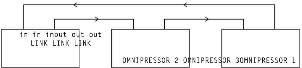
| CONNECTIONS | In stereo and master linking modes, units should be daisy-chained in a loop, LINK-OUT to LINK-IN, as shown below. Standard TS or TRS audio patch cables may be used. |
flowchart
graph TD
    A["in in out LINK"] --> B["LINK LINK"]
    A --> C["OMNIPRESSOR 2 OMNIPRESSOR 30MNIPRESSOR 1"]
    A --> D["in in out LINK"]
    C --> D
MULTI-UNIT LINKING---BLOCK DIAGRAM
APPLICATIONS
YOUR OMNIPRESSOR LOVES YOU AND WANTS TO BE YOUR FRIEND!
If you don't understand it, if you don't fondle its controls properly, it will cause you hours of confusion, and tempt you to dash it on the rocks or put it in a sack and drown it. PLEASE READ this applications section before blaming your Omnipressor for malfeasance or deviltry.
The Omnipressor, like most Eventide equipment, is a signal processor with wide-ranging use. It is not the normal, tame limiter or compressor which only tries to keep signals within a certain range. It is not a simple noise gate which is either off, letting nothing through, or on, letting everything through at unity gain. Rather, it is a special effects unit, which, in addition to the above, can generate such effects as infinite compression, dynamic reversal, extreme expansion, etc. The Omnipressor has a 60dB control range in addition to a wide dynamic range at constant gain. Because of this wide range, it is possible to overload system components following the Omnipressor if it is used improperly. Note, for instance, that with the output control wide open, and with the gain reading +30 on the meter, it is possible to obtain up to 50dB gain from the unit. If you connected an amplifier with 50dB gain between your console out and your tape recorder in, you might reasonably expect some distortion, right? Right!
Before using the Omnipressor in a session or in a performance, familiarize yourself with its operation. The ATTEN and GAIN LIMIT controls serve to prevent uncontrolled operation by the novice user. Turn on the Omnipressor and turn the threshold control to zero. With no input, the level detector stage is producing the maximum possible control voltage. With no input, putting the FUNCTION knob in the expand section causes a great reduction in gain. As the input increases, the control voltage gets closer to 0, and the gain reduction decreases, until, at some point, set by the threshold control, the gain starts increasing past unity (0dB). This is expansion – increasing gain with increasing signal, thus increasing dynamic range. Note how sharply the FUNCTION control varies the gain with no input signal. Also note that as the signal level approaches the threshold, the function control has a less pronounced effect, until, at the threshold, full rotation has almost no effect.
Experiment with the two LIMIT controls. Again remove the input signal. Turn the two limit controls fully clockwise. Observe that the FUNCTION control can only vary the meter by a few dB, despite the fact that with no input, maximum expansion or compression should occur. Rotate the FUNCTION control to maximum expansion and vary the ATTEN LIMIT control. Notice that the meter varies from negative full scale to almost center scale. Now, rotate the GAIN LIMIT control. Note that this control has no effect on the meter reading. Turn the FUNCTION control to maximum compression and repeat the experiment with the LIMIT controls. Note that now the GAIN LIMIT varies the meter reading from center to positive full scale, and the ATTEN LIMIT control has no effect.
The LIMIT controls are very important in setting up the unit. They can prevent runaway gain, runaway attenuation, runaway engineer, and many other problems. For instance, if you wish to increase average program level by 10dB, but limit compression to a maximum of 15dB, set the GAIN LIMIT control with no input and the FUNCTION knob at full compress so that the meter reads +10 in the GAIN position. Now, turn the FUNCTION knob to full expand and set the meter at -5 with the ATTEN LIMIT control. You are now free to set the compression ratio, threshold, and time constant for the most pleasing performance without worrying that you will get too much gain, too much attenuation, or uncontrolled operation, regardless of signal levels or peaks. This type of setability is perfect for sound reinforcement or broadcast use where unattended operation is the rule and wild effects are not desired. Controllable compression in sound reinforcement is particularly advantageous because feedback can be prevented conclusively while still permitting maximum output.
Another control not customarily found on dynamic modifiers is the BASS CUT switch. Unlike the LIMIT controls, it is not exceptionally useful. Its main application is to prevent large gain variations from being initiated by low frequency signals. A typical use would be in communications or advertising applications, where it is frequently desirable to give a signal as much “punch” as possible. Information in voice signals is generally carried in the range above 500Hz, although fundamentals are present below this frequency. By using a short time constant and cutting bass response, an improvement in intelligibility can be obtained in listening environments with less than optimum signal-to-noise ratios. Additional applications would be in processing signal tracks with leakage present. If, for instance, the bass drum leaked onto the voice track which you are limiting, the bass can be prevented from affecting the gain control operation. (Note that this does not reduce the amplitude of the leakage. Refer to the Noise Gate description for more information on reducing leakage.)
The Model 2830*Au Omnipressor may be used as a fast peak limiter. By setting the ATTACK TIME constant control to 100μs, the unit in effect no longer is an RMS responding detector, but rather follows peaks in the input signal. At this rate a single half cycle of 5kHz tone above the threshold is sufficient to reduce the Omnipressor gain by about 10dB. Smaller peaks at even higher frequencies can be limited at this setting. Bear in mind that at very fast attack times, limiting is equivalent to clipping, and if the signal level is frequently above the threshold, harmonic distortion will be increased.
The above material gives general considerations for the operation of the Omnipressor. The remainder of this applications section is organized as a group of individual “application notes.” If you have a specific application that you wish to make known, please join our forum at eventideaudio.com.
APPLICATION NOTE #1 "Your Backwards Omnipressor"
As we state in our promotional literature, one of the novel features of the Omnipressor is its ability to make signals sound backward. This is a consequence of the Dynamic Reversal feature, which enables loud sounds to come out more softly than soft sounds. Speech waveforms, for instance, generally consist of loud peaks followed by trailing-off envelopes. By making these envelopes louder than the peaks, the illusion that the sound is coming out backward is generated. Likewise, drum sounds consist of peaks roughly coincident with mechanical impact, followed by a decay envelope. The Omnipressor amplifies this envelope and “swallows” the impact.
The reversal effect is not limited to voice and drums. In general, any material with wide dynamic range can be “reversed.” Plucked string instruments, virtually all percussion, and many natural sounds can be processed to good effect. Certain other material does not sound good in the reversal mode. Specifically, program material consisting of more than one type of sound will give inconsistent results at best. Trying to process an entire program source rather than individual tracks will generally meet with ignominious failure, although solos can be picked out and reversed on occasion.
CONTROL SETTINGS
| LINE | ON | ||
| FUNCTION | -2 COMPRESS | ||
| ATTEN/GAIN | LIMIT | FULL | CCW |
| TIME CONSTANT | ATTACK 5ms, RELEASE | 100ms | |
| THRESHOLD | 0 | ||
| OUTPUT | 0 | ||
| METER | GAIN | ||
Experiment with the operational controls to obtain the most pleasing effect. It will probably be desirable to limit the maximum gain somewhat with the GAIN LIMIT control to prevent high noise levels with no signal. This applies particularly to taped material in which noise reduction was not employed.
ADDITIONAL POSSIBILITIES
If you can make forward things sound backward, you should be able to make backward things sound forward! Play a vocal tape backward and reverse the dynamics. The voice should come out sounding almost normal, but the words will be pure gibberish. If you want tremendous “punch” on recorded material, record it normally, and then play it backward through the Omnipressor set barely into the reversal mode, and re-record it. Playing the second tape backward (i.e. voice forward), should result in a signal almost completely devoid of dynamic range. Also, you can use the second recording as an opportunity to add some echo, which will then precede the signal in real time. The reason backward compression is so effective is that the program material is devoid of sharp attack transients which tend to bring down the succeeding program material.
PRESENTING:
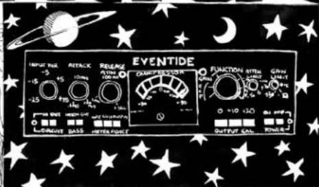
Eventide
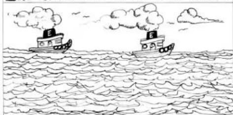
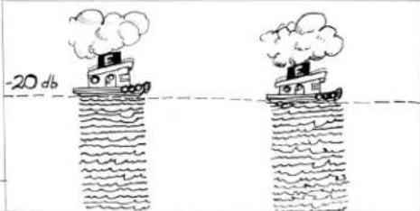
SETTHRESHOLD AT LEVELOFWATER
natural_image
Simple line drawing of two steamboats on the sea with smoke clouds, no text or symbols present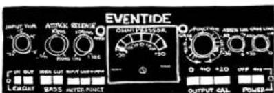
THE NOISE GATE
WATER PRESENT ONLY WHEN BOATS PRESENT
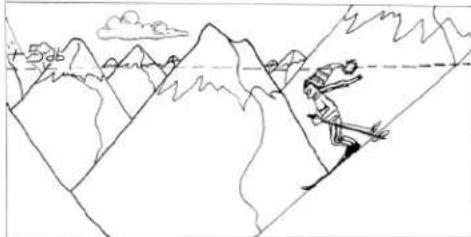
SET A MAXIMUM LEVEL ....
natural_image
Line drawing of a person skiing across mountainous terrain with clouds and sky in the background (no text or symbols)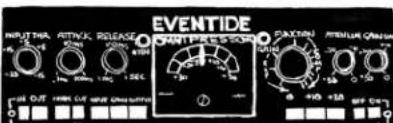

THE LIMITER
ABOVE MAX. LEVEL, NOTHING GETS THROUGH
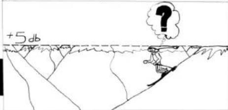
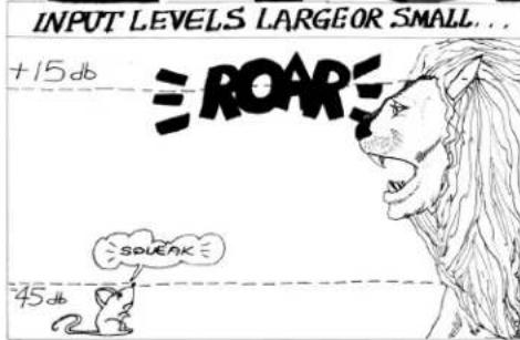
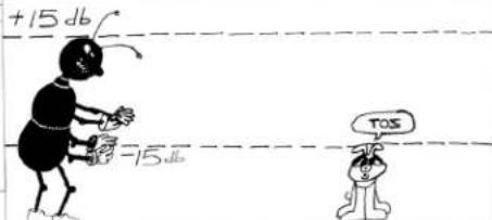
PUT A SMALLAND LARGE INPUT IN
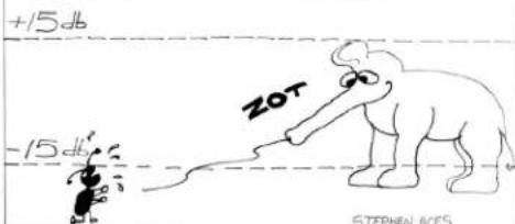
THE DYNAMIC REVER.SER
GET A LARGE AND SMALL OUTPUT OUT
AND NOW!NEW FEATURES!
NOW THE OMNIPRESSOR IS AVAILABLE WITH INDEPENDENTLY VARIABLE ATTACK AND RELEASE TIMES; MICRO TO MILL SECONDS! CATCH PEAKS, OR AVERAGE YOUR SIGNAL FOR TRUE R.M.S. LIMITING:

AND: as an added bonus,
CALIBRATED EXTRA GAIN AT THE TOUCH OF A BUTTON; UP TO 20 db!
THE OMNIPRESSOR, FROM EVENTIDE 265 WEST 54 ^th ST. NYC 10019
APPLICATION NOTE #2
Our advertisement opposite depicts in cartoon form the various standard operating modes of the Omnipressor. This note gives the initial control settings to achieve the effects depicted. The following settings apply to all modes:
LINE......ON BASS CUT......OFF TIME CONSTANT...ATTACK 5ms, RELEASE 100ms (except in GATE and LIMITER) INPUT SIGNAL should be available 10-20dB over THRESHOLD setting.
| ATTEN/GAIN LIMITMETERFUNCTION | INFINITE COMPRESSORFULL CCWOUTPUT∞. Apply signal from oscillator and vary input amplitude.Adjust FUNCTION control slightly until varying input has no effect on output level. |
| ATTEN/GAIN LIMITMETERFUNCTION | EXPANDERFULL CCWGAINAS DESIRED between 1 and 2. Use GAIN LIMIT if needed for wide expansion range. |
| ATTEN LIMITGAIN LIMITMETERFUNCTIONATTACK TIMERELEASE TIMETHRESHOLD | NOISE GATECCWFULL CWGAIN10 EXPAND100μsAS DESIREDADJUST FOR DESIRED GATING ACTION. |
| ATTEN LIMITGAIN LIMITMETERFUNCTIONTHRESHOLD | LIMITERCCWFULL CWGAIN∞ADJUST FOR LEVEL AT WHICH LIMITING IS DESIRED. |
| ATTEN LIMITGAIN LIMITMETERFUNCTION | DYNAMIC REVERSERCCWCCWGAIN-1 |
Best settings of all controls will greatly depend upon program material.
APPLICATION NOTE #3 VOLTAGE CONTROLLED AMPLIFIER
The Omnipressor may be used as a high-quality voltage controlled amplifier for modulation, electronic music, channel gain variation, amplitude scaling, filter generation, or, in fact, any application in which a fader or potentiometer is used. Characteristics in the voltage control mode include accurate voltage vs. amplitude curve, good tracking, low distortion regardless of signal level (below clipping level), and wide control range.
The gain control section of the Omnipressor has a linear control voltage vs. decibel output characteristic. This is equivalent to a logarithmic control voltage vs. output voltage curve. This makes it especially useful for audio and musical applications in which logarithmic response and logarithmic signal decay envelopes are prevalent. The control range available Is 60dB. Gain is decreased with a positive control voltage and increased with a negative control voltage.
To operate the Omnipressor in the VCA mode, set the four internal link-mode jumpers to the MTR LINK position. In this mode, the TS LINK_IN jack acts as a VCA input. (See LINKING section). Characteristics of the VCA section are as follows:
Input impedance nominal 18K ohms Input voltage range +12 to -12V DC Control characteristic .4 volts per decibel Linearity ±1dB Center: no input signal gives 0 gain ±1dB Frequency response essentially flat to 10kHz Gain slew rate approx. 1dB per microsecond
In the voltage control mode, the FUNCTION control and GAIN LIMIT and ATTEN LIMIT controls are disabled, as are the time constant controls and the BASS CUT. The INPUT, MIX and OUTPUT controls remain functional, and the METER and indicator lights operate.
The audio signal in the Omnipressor is theoretically “modulated” by the control voltage. However, due to the logarithmic characteristic of the control, and the unipolar nature of the control (reversing control polarity does not reverse output phase), it is recommended that the Omnipressor NOT be used as a balanced modulator (multiplicative mixer) except on an experimental basis.
APPLICATION NOTE #4 PREDICTIVE COMPRESSION
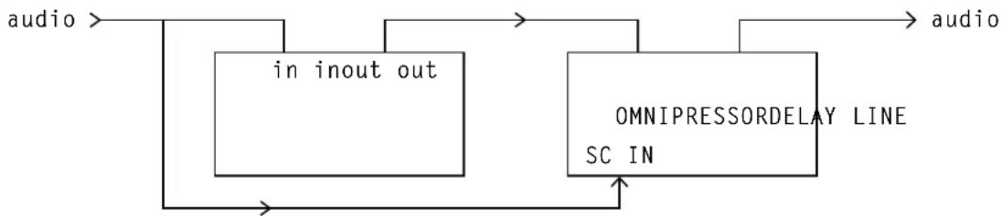
In a previous note, we discussed the possibility of compressing material in reverse order to eliminate the compressor's inherent problem with fast attack transients. In a limiter, fast transients are in effect eliminated by signal clipping before the system gain can adjust to the new level. In a normal compressor, short bursts of high level material can get through before the gain can adjust. The first method creates varying amounts of distortion. The second engenders such phenomena as "p popping." The unique ability of the Omnipressor to separate the gain control from the level detector enables one to build what is most conveniently termed a "predictive" compressor. Such a unit should go a long way towards eliminating the unavoidable imperfections standard units have.
flowchart
graph TD
    A["audio"] --> B["in inout out"]
    B --> C["OMNIPRESSORDELAY LINE SC IN"]
    C --> D["audio"]
PREDICTIVE COMPRESSOR---BLOCK DIAGRAM
Connect an Omnipressor and an Eventide Digital Delay Line together as shown above. Enable the sidechain input. What you have just fabricated is a compressor that can read the future, or, in more common parlance, one which has a negative attack time. It works as follows: A signal comes into the level detector via the sidechain, which reacts to it depending upon the settings of the controls. Simultaneously, the signal is fed into the delay line which delays it by one or more milliseconds. The signal is then fed to the gain control section of the second Omnipressor. During this delay interval, the level detector has reached the optimum output voltage for the input signal, and before the time the signal reaches the gain control module, the gain has adjusted to the level of the signal.
This predictive mode of operation requires some experimentation to match the signal delay time to the Omnipressor time constant, but when the system is properly adjusted, a very close approximation to the “ideal compressor” is realized.
LIMITATIONS
This type of operation is particularly effective in applications in which only one signal must be processed. To maintain synchronism, a channel of delay is required for each channel of audio, whether or not that channel is to be otherwise processed. This would become cost prohibitive in any configuration exceeding stereo. There is much room for experimentation. We would be pleased to know of your results and techniques.
APPLICATION NOTE #5 USE OF THE OMNIPRESSOR AS A NOISE REDUCTION UNIT
The Omnipressor makes a good compression/expansion noise reduction unit for enhancing the transmission capability of some media such as tape, digital equipment, low grade phone lines, etc. While it will not replace a good noise reduction unit such as the DBX or the Dolby for tape (devices intended primarily for noise reduction applications have frequency response tailoring), it will serve in a pinch when one of these devices is not available.
If the Omnipressor is set up as a compressor on the input end (feeding the tape machine or phone line) and as an expander on the output end, then the input dynamic range is compressed during transmission and a medium with, say, 40dB dynamic range can appear to have a much wider range. If the input is compressed by a two to one range, and the output is expanded by a factor of 2 to 1, an apparent 80dB range exists for the transmission channel. In practice, this does not precisely obtain, but a very substantial audible improvement is possible with such processing. Since identical circuitry with identical time constants is used to produce compression and expansion, perfect dynamic tracking is obtained. If compression and expansion ratios are set properly, the system should be transparent to the listener.
INITIAL SET UP
LINE ON
THRESHOLD -10
ATTACK TIME 5ms
RELEASE TIME 50ms
BASS CUT OFF
METER FUNCTION GAIN
OUTPUT CAL 0
ATTEN LIMIT CCW
GAIN LIMIT CCW
Set the FUNCTION control to a compression ratio of 2 for tape recording or sending signals on a transmission channel. Set the FUNCTION control to an expansion ratio of 2 to decode the compressed signal. To go from record to playback with a single Omnipressor, adjusting the FUNCTION control is the only required adjustment. If simultaneous encode and decode is required, be sure that both Omnipressors have identical front panel adjustments.
Only the basic setup is given above. You might wish to experiment with compression/expansion ratios. Also, with certain types of signals, it might be desirable to put the BASS CUT switch ON. Remember that the setup for encode and decode (compress and expand) should be identical except for the complementary setting of the FUNCTION control.
TECHNICAL DATA
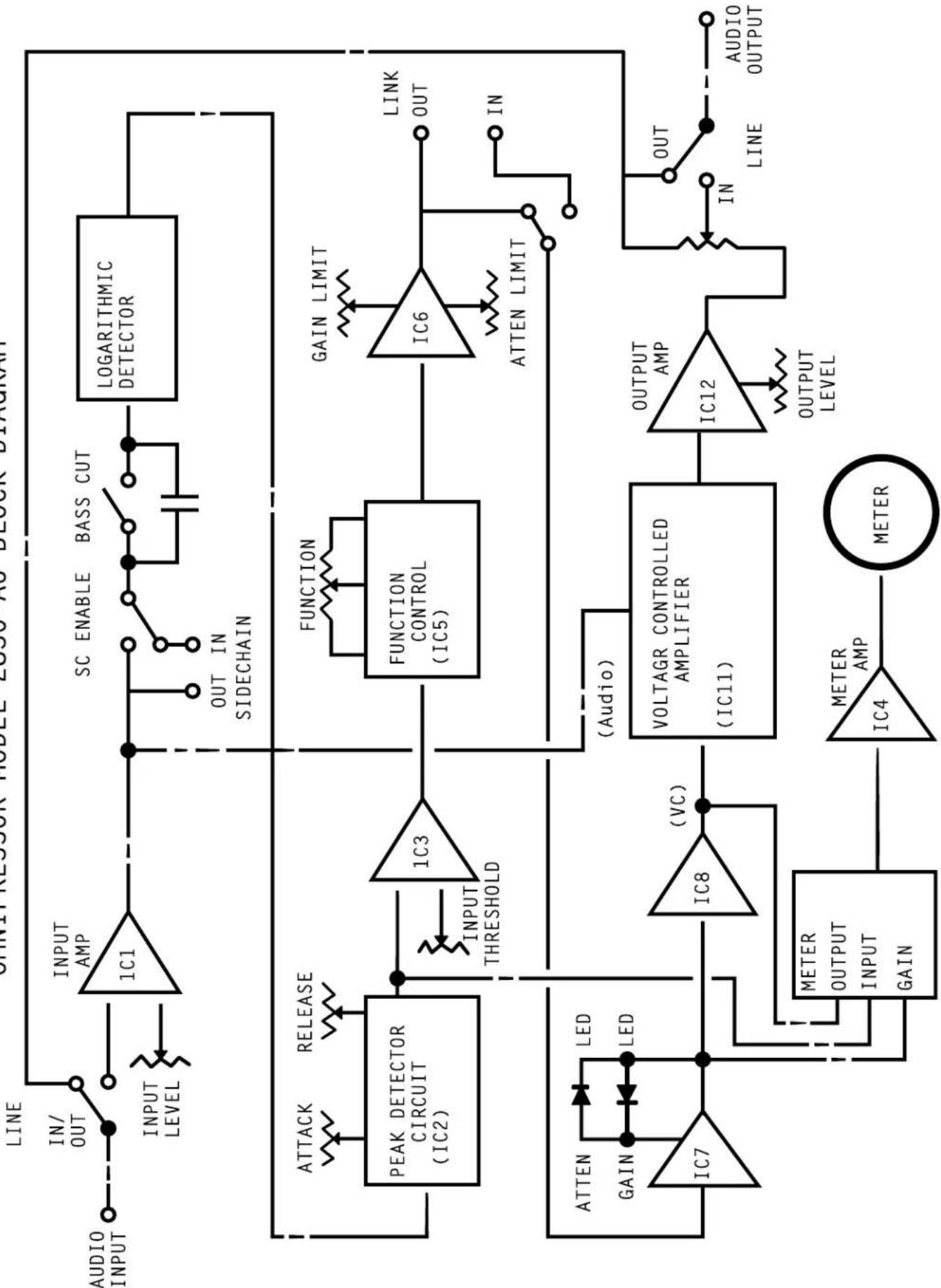
OMNIPRESSOR MODEL 2830*AU BLOCK DIAGRAM
flowchart
graph TD
    A["LINE"] --> B["INPUT AMP 1C1"]
    B --> C["SC ENABLE"]
    C --> D["BASS CUT"]
    D --> E["LOGARITHMIC DETECTOR"]
    E --> F["OUTPUT LEVEL"]
    F --> G["METER OUTPUT INPUT GAIN"]
    G --> H["METER AMP IC4"]
    H --> I["METER"]
    J["PEAK DETECTOR CIRCUIT (IC2)"] --> K["INPUT THRESHOLD"]
    L["ATTEN GAIN"] --> M["LED"]
    M --> N["IC7"]
    O["IN"] --> P["IN"]
    Q["OUT"] --> R["IN"]
    S["IN"] --> T["IN"]
    U["GAIN LIMIT"] --> V["FUNCTION CONTROL (IC5)"]
    W["VOLTAGR CONTROLLED AMPLIFIER (IC11)"] --> X["IC6"]
    X --> Y["ATTEN LIMIT"]
    Y --> Z["LINK OUT"]
    AA["LINE"] --> AB["OUTPUT LEVEL"]
    AC["AUDIO OUTPUT"] --> AD["OUTPUT AMP IC12"]
    AE["LINE"] --> AF["OUTPUT LEVEL"]
    AG["IN"] --> AH["IN"]
    AI["IN"] --> AJ["IN"]
    AK["INTERNATIONAL MODELE LOGO AS BLOCK DIAGRAM"] --> AL["LINE"]
    AL --> AM["INPUT LEVEL"]
    AL --> AN["OUTPUT LEVEL"]
THEORY OF OPERATION
The unique features of the Omnipressor, Infinite Compression and Dynamic Reversal, are obtained by a process known as “open loop” operation. A standard, non-open loop compression amplifier operates as follows: the input signal goes through a gain control stage, after which the level is detected. If the output level is too high, a voltage is applied to the gain control stage to lower the output. Thus, the higher the compression ratio, the higher the gain of the amplifier necessary in the level detect or to control the output level. Obtaining extremely high compression requires extremely high gain, which requires critical circuitry and can cause instability. This standard type of operation is referred to as “closed loop” because the processed signal level is used to determine further changes in its own amplitude.
Open loop processing, as employed by the Omnipressor, uses a completely independent level detector and gain control stage. The level detector produces a DC output proportional to the AC RMS input. This voltage is linear with respect to the input level variation in decibels. An input change from -30 to -10dB produces the same DC change as does an input change from +10 to +30dB, even though the actual input change measured in absolute terms is much greater. Likewise, the gain control module gives a fixed dB change for a given control change in control voltage, regardless of whether the module gain is -30 or +30dB.
Now, consider what happens when an input signal is applied to both the gain control module and the level detector module. We apply a 0dB signal and note that the level detector output is +1 volt. (All the numbers in this example are chosen for simplicity. Actual values will be different.) Now, we apply a +10dB signal and note that the level detector output is +2 volts. Assuming that the gain control module works on the same levels (.1 volt per decibel), we can take the DC output from the level detector, apply it to an inverting amplifier, and thence to the gain control module. Depending upon the gain of the inverting amplifier, various compression ratios are available.
| INVERTINGAMPLIFIERGAIN | INPUT LEVELCHANGE | OUTPUT LEVELCHANGE | COMPRESSIONRATIO |
| .5 | 10dB | 5dB | 2 |
| .75 | 10dB | 2.5dB | 4 |
| .90 | 10dB | 1dB | 10 |
| .95 | 10dB | .5dB | 20 |
| .99 | 10dB | .1dB | 100 |
| 1 | 10dB | 0 | infinite |
| 1.5 | 10dB | -5dB | -2 |
| 4 | 10dB | -40dB | -.25 |
As can be seen, a wide variety of compression ratios can be obtained with no critical high-gain DC amplifiers. Implementation of the various Omnipression functions is achieved as follows:
The balanced or unbalanced audio input signal is transformer isolated and buffered. The buffered signal goes to the logarithmic amplifier via the BASS CUT switch, which inserts a series capacitor into the signal path in the CUT position. This capacitor, combined with the log detector's input impedance of 2.4K, forms a 200Hz bass cut filter. (Note that the audio path bass response is unaffected by this capacitor.)
The log detector uses a chain of limiting amplifiers, whose outputs are summed in a log IC whose output is a bipolar (AC) differential signal whose voltage varies at 60mv. A balanced modulator with differential input is used to amplify, level shift, and full-wave-rectify the log signal. The end of the limiting amp chain sends a zero-crossing signal to the carrier input of an op amp. This signal is diode limited. This enables the op amp to act as a synchronous rectifier, so that the succeeding detection circuitry will act on either positive or negative peaks. A differential amplifier comes next which buffers, amplifies, and level-shifts resulting in a 1 volt/decade signal with OV DC output for no input.
The output from this stage is peak detected by a high slew rate operational amplifier. The output charges a capacitor connected to a variable resistor which sets the attack time. The capacitor is discharged at a rate determined by circuitry that determines the release time. (Note that this circuitry enables attack times to be slower than decay times.)
Another op-amp inverts and level-shifts the detected signal so that its output is 0V for inputs equal to the input threshold control setting. The input and output of this op-amp are applied to either end of the FUNCTION control. A variable gain and polarity signal is present on the wiper of the FUNCTION control with resistive loading resulting in a parabolic control. The ATTEN and GAIN LIMIT controls limit the amplifiers swing, corresponding to 0 to -30dB attenuation limit.
The buffered input audio is applied to the VCA module signal input. A DC offset trimpot nulls harmonic distortion in the VCA.
The meter circuit sums and offsets the various DC signals determined by the METER function switch. Trimpots set the gain and offset for each function.
Eventide®
OMNIPRESSOR®
2830\*Au
- OMNIPRESSOR MODEL 2830\*Au
- TABLE OF CONTENTS
- SECTION 1 INTRODUCTION
- SECTION 2 CONNECTION AND OPERATION
- Application Notes
- SECTION 3 TECHNICAL DATA
- GENERAL DESCRIPTION
- OMNIPRESSOR INTERFACE
- CONTROL AND INDICATOR DESCRIPTION
- METER FUNCTION
- FUNCTION
- OUTPUT LEVEL
- ATTEN LIMIT
- GAIN LIMIT
- LINK
- POWER ON/OFF
- CONTROL AND INDICATOR DESCRIPTION (cont.)
- LINKING
- APPLICATIONS
- APPLICATION NOTE #1 "Your Backwards Omnipressor"
- ADDITIONAL POSSIBILITIES
- PRESENTING:
- Eventide
- AND NOW!NEW FEATURES!
- AND: as an added bonus,
- APPLICATION NOTE #2
- APPLICATION NOTE #3 VOLTAGE CONTROLLED AMPLIFIER
- APPLICATION NOTE #4 PREDICTIVE COMPRESSION
- LIMITATIONS
- APPLICATION NOTE #5 USE OF THE OMNIPRESSOR AS A NOISE REDUCTION UNIT
- INITIAL SET UP
- TECHNICAL DATA
- THEORY OF OPERATION
- Eventide®
- OMNIPRESSOR®
- 2830\*Au
Brand : EVENTIDE
Model : Omnipressor 2830Au
Category : Compressor