
IB-574SSK-12G - Uncategorized Icy Box - Free user manual and instructions
Find the device manual for free IB-574SSK-12G Icy Box in PDF.


| Product Type | 4-Bay Hard Drive Enclosure |
| Model | IB-574SSK-12G |
| Brand | Icy Box |
| Form Factor | Desktop / Rackmount |
| Supported Drive Size | 2.5" or 3.5" SATA/SAS HDD/SSD |
| Number of Bays | 4 |
| Interface | Mini-SAS HD (SFF-8643) to 1x SFF-8087 internal cable |
| Data Transfer Rate | Up to 12 Gbps per port (SAS 3.0) |
| Backplane | SAS 12Gbps with SGPIO support |
| Cooling | 1 x 80mm fan (rear) |
| Power Supply | Internal AC adapter, Input 100-240V, Output 12V DC |
| Material | Aluminum body with steel tray |
| LED Indicators | Power, HDD activity per bay |
| Security | Key lock on each drive tray |
| Dimensions (W x D x H) | 215 x 160 x 125 mm |
| Weight | 1.2 kg (without drives) |
| Operating Temperature | 5°C to 35°C |
| OS Support | Windows, macOS, Linux (requires appropriate SAS controller) |
| Maintenance | Tool-less drive installation; removable fan filter |
| Spare Parts Availability | Fan, power adapter, drive trays available from manufacturer |
| Warranty | 2 years limited warranty |
Frequently Asked Questions - IB-574SSK-12G Icy Box
User questions about IB-574SSK-12G Icy Box
0 question about this device. Answer the ones you know or ask your own.
Ask a new question about this device
Download the instructions for your Uncategorized in PDF format for free! Find your manual IB-574SSK-12G - Icy Box and take your electronic device back in hand. On this page are published all the documents necessary for the use of your device. IB-574SSK-12G by Icy Box.
USER MANUAL IB-574SSK-12G Icy Box
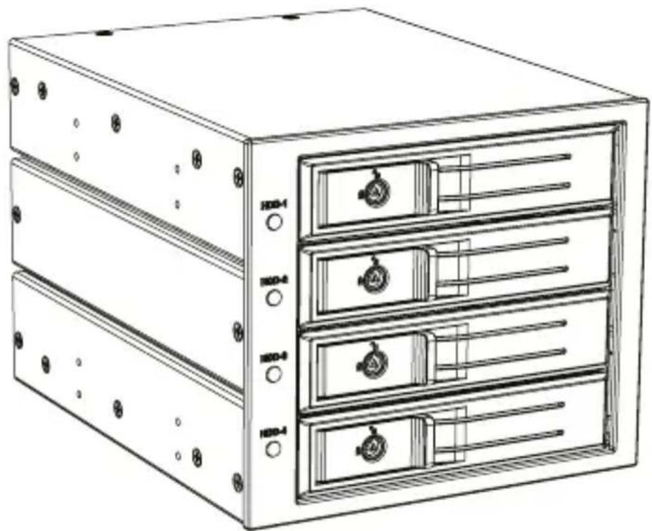
4x 3.5" SATA/SAS HDD Backplane
4x 3.5" SATA/SAS HDD Backplane
natural_image
Line drawing of a multi-chamber server rack unit with labeled ports (HDD-1, HDD-2, HDD-3, HDD-4) and control knobs (no text or symbols on the device itself)Manual IB-574SSK-12G
Please read carefully the following information to prevent injuries, damage to material and device as well as data loss:
Warning levels
Signal words and safety codes indicate the warning level and provide immediate information in terms of the probability of occurrence as well as the type and severity of the consequences if the measures to prevent hazards are not complied with.

DANGER
Warns of a directly hazardous situation causing death or serious injury.

WARNING
Warns of a potentially hazardous situation that may cause death or serious injury.

CAUTION
Warns of a potentially hazardous situation that may cause minor injury.
IMPORTANT
Warns of a potential situation that may cause material or environmental damage and disrupt operative processes.
1. Risk of electrical shock

WARNING
Contact with parts conducting electricity
Risk of death by electrical shock
- Read the operating instructions prior to use
• Make sure the device has been de-energised prior to working on it - Do not remove contact protection panels
- Avoid contact with conducting parts
- Do not bring plug contacts in contact with pointed and metal objects
• Use in intended environments only - Operate the device using a power unit meeting the specifications of the type plate only!
- Keep the device/power unit away from humidity, liquid, vapour and dust
• Do not modify the device
• Do not connect the device during thunderstorms - Approach specialist retailers if you require repairs
2. Hazards during assembly (if intended)

CAUTION
Sharp components
Potential injuries to fingers or hands during assembly (if intended)
- Read the operating instructions prior to assembly
- Avoid coming into contact with sharp edges or pointed components
• Do not force components together - Use suitable tools
• Use potentially enclosed accessories and tools only
3. Hazards caused by a development of heat
IMPORTANT
Insufficient device/power unit ventilation
Overheating and failure of the device/power unit
- Prevent externally heating up components and ensure an exchange of air
- Do not cover the fan outlet and passive cooling elements
Manual IB-574SSK-12G
- Avoid direct sunlight on the device/power unit
• Guarantee sufficient ambient air for the device/power unit - Do not place objects on the device/power unit
4. Hazards caused by very small parts and packaging

WARNING
Risk of suffocation
Risk of death by suffocation or swallowing
- Keep small parts and accessories away from children
- Store/dispose of plastic bags and packaging in an area that is inaccessible to children
• Do not hand over small parts and packaging to children
5. Potential data loss
IMPORTANT
Data lost during commissioning
Potentially irreversible data loss
- Always comply with the information in the operating instructions/quick installation guide
• Exclusively use the product once the specifications have been met
• Back up data prior to commissioning
• Back up data prior to connecting new hardware
• Use accessories enclosed with the product
6. Cleaning the device
IMPORTANT
Harmful cleaning agents
Scratches, discolouration, damage caused by moisture or short circuit in the device
- Disconnect the device prior to cleaning
- Aggressive or intense cleaning agents and solvents are unsuitable
• Make sure there is no residual moisture after cleaning
• We recommend cleaning devices using a dry, anti-static cloth
7. Disposing of the device
IMPORTANT
Environmental pollution, unsuitable for recycling
Potential environmental pollution caused by components, recycling circle interrupted
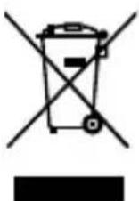
This icon on product and packaging indicates that this product must not be disposed of as part of domestic waste. In compliance with the Waste Electrical and Electronic Equipment Directive (WEEE) this electrical device and potentially included batteries must not be disposed of in conventional, domestic waste or recycling waste. If you would like to dispose of this product and potentially included batteries, please return it to the retailer or your local waste disposal and recycling point.
If you have any questions, please do not hesitate to contact our support at support@raidsonic.de or visit our website at www.icybox.de.
• Full aluminium and steel backplane for 3x 5.25" bays
- Host connector: Mini SAS HD (SFF-8643) data interface with up to 12 Gbit/s
• Supports 4x SATA III (6 Gbit/s) or 4x SAS III (12 Gbit/s) drives
• Key lock to secure each inserted drive
• HotSwap and Plug & Play, no capacity limit
• LED indicators for power, HDD access, fan failure, temperature alarm
- 80x80 mm cooling fan
• Temperature alarm adjustable to 55^ C, 60^ C or 65^ C
• Supports Windows® and macOS®
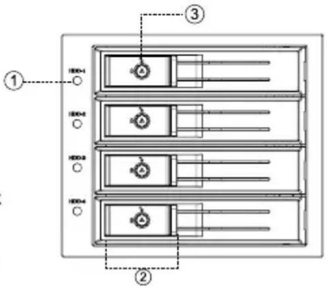
Front view
- LED indicator
- Handle for unlocking
- Lock
Lock
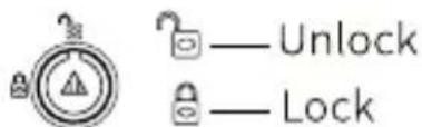
Use the key to unlock the lock by turning it 90 degrees clockwise.
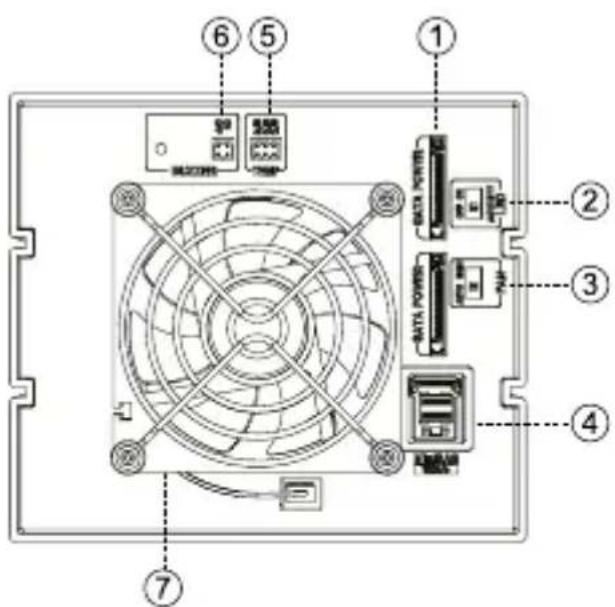
Back view
- 2x 15-pin SATA power port
- ON/OFF switch for LED hard disk activity
- Switch for fan speed (Auto/High)
- Mini SAS HD (SFF-8643) data interface
- Setting of the range for temperature alarm
- Setting (ON/OFF) alarm buzzer
- 80x80 mm fan
Manual IB-574SSK-12G
Hardware installation
- Switch OFF the PC and all other connected peripheral devices.
- Unplug the power cable from the back of the PC and remove the cover of your PC.
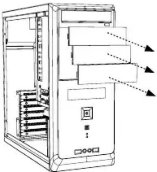
- Remove the covers of the available 3x 5.25" bays.
natural_image
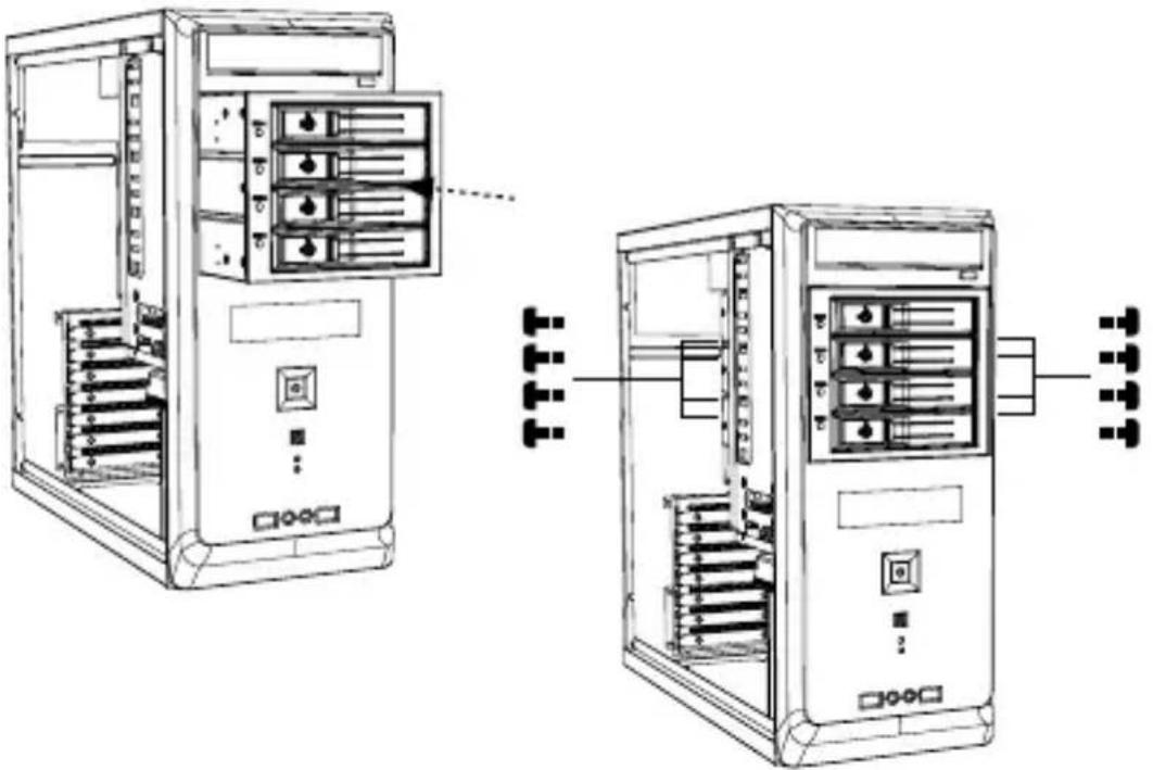
Technical line drawing of a desktop computer tower with visible internal components and ventilation ducts (no text or labels)- Insert the backplane into the bay and fix it with 4 screws on each side.
natural_image
Technical line drawing of two server rack units with internal components and connection lines (no text or symbols)Manual IB-574SSK-12G
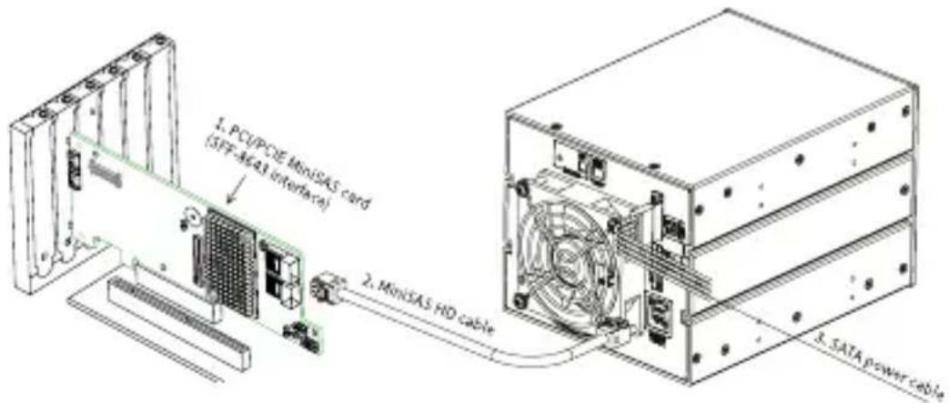
- Connect the Mini SAS HD interface of the backplane to a Mini SAS HD interface of the host PC by a Mini SAS HD cable (not included)
-
Then connect the two 15-pin SATA power ports with two 15-pin SATA power cables to two 15-pin SATA power connectors on the host PC. Note: It requires more power to allow three 3.5" drives working at the same time.
-
Replace the PC cover and reconnect the power cable of the PC.
Manual IB-574SSK-12G
Drive installation
Attention
- Do not force to close the door if inserting the drive in the wrong direction, or the drive and/or the backplane will be damaged.
-
Drives should be handled carefully, especially when you transport them, otherwise you may experience lost or corrupted data.
-
If the door is locked, use the key to unlock. Then pull the door handle open.

natural_image
Diagram of a server rack with a hand inserting a component, showing internal structure and rotation arrow (no text or symbols)- Gently insert the drive (printed side up) into the enclosure and close the door.
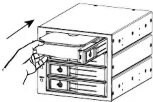
natural_image
Illustration of a hand inserting a drive into a rack-mounted server unit (no text or symbols visible)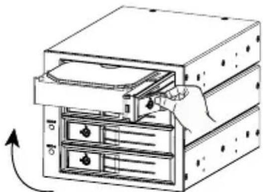
natural_image
Diagram of a computer tower with an open drive and internal storage racks, showing a hand inserting a cable into the rack (no text or symbols present)- Lock the door by key if needed.
Manual IB-574SSK-12G
During operation
1. LED indicators
Power indicator: Blue LED lights up constantly Access indicator: Blue LED flashes Fan failure: Orange LED flashes Temperature notice: Red LED flashes
2. Fan failure alarm
If the fan fails, the buzzer activates and the orange LED flashes. The orange LED stops flashing when the function returns to normal. Attention Note: The built-in fan works with the integrated temperature control system of the backplane. Changing the fan with other models may affect the function.
3. Temperature alarm
If the temperature is above the setting, the buzzer activates and the red LED flashes. The red LED stops flashing when the temperature returns below the setting. Attention Note that the drives can reach temperatures of 50^ C or higher during operation. Risk of injury when removing the drives!
4. ON/OFF switch for LED hard disk activity
OFF: Switching off the activity indicator ON: Switching on the activity indicator
AUTO: When the internal temperature reaches 30^ C, the fan starts running. The fan speed is automatically adjusted to temperature changes. The fan rotates at the highest speed when the temperature reaches 40^ C.
HIGH: The fan already rotates at the highest speed when the temperature reaches 30^ C.
(When the backplane is just powered on, the fan will run for a few seconds as self-test and then stops.)
6. Setting (ON/OFF) for alarm buzzer
OFF: Deactivating the buzzer sound ON: Switch on the buzzer sound
7. Setting the temperature alarm range
Temperature alarm can be set to 55°C, 60°C or 65°C
natural_image
Technical line drawing of a desktop computer tower with visible internal components and ventilation ducts (no text or labels)natural_image
Technical line drawing of two server rack units with internal components and connection points (no text or symbols)natural_image
Diagram of a server rack with multiple tiers and a hand inserting a component (no text or symbols)natural_image
Diagram showing two views of a server rack with an open panel, one being inserted and the other being removed (no text or symbols present)© Copyright 2023 by RaidSonic Technology GmbH. All Rights Reserved. The information contained in this manual is believed to be accurate and reliable. RaidSonic Technology GmbH assumes no responsibility for any errors contained in this manual. RaidSonic Technology GmbH reserves the right to make changes in the specifications and/or design of the above-mentioned product without prior notice. The diagrams contained in this manual may also not fully represent the product that you are using and are there for illustration purposes only. RaidSonic Technology GmbH assumes no responsibility for any differences between the product mentioned in this manual and the product you may have. Apple and macOS are registered trademarks of Apple Computer Inc. Microsoft, Windows and the Windows logo are registered trademarks of Microsoft Corporation.
- Manual IB-574SSK-12G
- Warning levels
- DANGER
- WARNING
- CAUTION
- IMPORTANT
- Risk of electrical shock
- Contact with parts conducting electricity
- Hazards during assembly (if intended)
- Sharp components
- Hazards caused by a development of heat
- Insufficient device/power unit ventilation
- Hazards caused by very small parts and packaging
- Risk of suffocation
- Potential data loss
- Data lost during commissioning
- Cleaning the device
- Harmful cleaning agents
- Disposing of the device
- Environmental pollution, unsuitable for recycling
- Front view
- Back view
- Hardware installation
- Drive installation
- Attention
- During operation
- LED indicators
- Fan failure alarm
- Temperature alarm
- ON/OFF switch for LED hard disk activity
- Setting (ON/OFF) for alarm buzzer
- Setting the temperature alarm range
Brand : Icy Box
Model : IB-574SSK-12G
Category : Uncategorized