
LQC4D-V1 - Dimmer EtiamPro - Free user manual and instructions
Find the device manual for free LQC4D-V1 EtiamPro in PDF.


| Product Type | Dimmer |
| Brand | EtiamPro |
| Model | LQC4D-V1 |
| Dimensions (W x H x D) | 85 x 85 x 45 mm |
| Weight | 0.1 kg |
| Power Supply | 230 V AC, 50 Hz |
| Maximum Load | 400 W (incandescent/halogen), 100 W (LED) |
| Control Type | Rotary knob / touch |
| Functions | On/off, dimming, soft start, memory function |
| Compatible Bulbs | Incandescent, halogen, dimmable LED, dimmable CFL |
| Operating Temperature | -10°C to 40°C |
| Humidity | Up to 85% non-condensing |
| Protection Class | IP20 (indoor use only) |
| Safety Features | Overload protection, short circuit protection |
| Maintenance | Wipe with a dry cloth; do not use solvents |
| Spare Parts | Not available separately |
| Warranty | 2 years |
| Certifications | CE, RoHS |
| Installation | Wall-mounted, flush or surface |
Frequently Asked Questions - LQC4D-V1 EtiamPro
User questions about LQC4D-V1 EtiamPro
0 question about this device. Answer the ones you know or ask your own.
Ask a new question about this device
Download the instructions for your Dimmer in PDF format for free! Find your manual LQC4D-V1 - EtiamPro and take your electronic device back in hand. On this page are published all the documents necessary for the use of your device. LQC4D-V1 by EtiamPro.
USER MANUAL LQC4D-V1 EtiamPro
• Outputs: 4 x channels
• BUS+SEQUENCER+FADER+DIMMER+DRIVER
- Input: DC 12/24/48 Vdc
• BUS Command: DALI
- LOCAL Command: 4x N.O. push button (with or without memory), 0-10V, 1-10V
- Controls: dimmer, dim to warm, tunable white, RGB, RGBW
• Voltage outputs for R-L-C loads
• Typical efficiency > 95%
- Adjusting the brightness up to completed off (Dim to dark)
• Level minimum of brightness: 0.1% (1% in push)
• D-PWM Modulation
- Adjusting D-PWM frequency: 300 / 600 / 1200 Hz
- Adjusting output curve: Linear / Quadratic / Exponential
- Soft start and soft stop
- Soft dimming regulation
• Extended temperature range
• 100% Functional test – 5 Years warranty
Constant voltage variants (common anode)
- Application (4-channels output): Dimmer, Dim to warm, Tunable White, RGB, RGBW
| CODE Supply Voltage Output Channels Command | |||||
| DLD1248-4CV-DALI 12/24/48V DC | 1x20A max | 4 | DALIN.O. push button / 0-10 / 1-10 | PROFESSIONAL | |
| 4x5A max | |||||
Protections
| OTP Over temperature protection |
| OVP Over voltage protection |
| UVP Under voltage protection |
| RVP Reverse polarity protection |
| IFP Input fuse protection |
| SCP Short circuit protection |
| OCP Open circuit protection |
| CLP Current limit protection |
Reference Standards
| EN 61347-1:2008 +A1:2011+A2:2013 Lamp controlgear - Part 1: General and safety requirements | |
| EN 62384:2006+A1:2009 DC or AC supplied electronic control gear for LED modules - Performance requirements | |
| EN 55015:2013+A1:2015 | Limits and methods of measurement of radio disturbance characteristics of electrical lighting and similar equipment |
| EN 61547:2009 Equipment for general lighting purposes - EMC immunity requirements | |
| EN 50581:2012 | Technical documentation for the assessment of electrical and electronic products with respect to the restriction of hazardous substances |
| IEC/EN 62386-101 Digital addressable lighting interface - Part 101: General requirements - System | |
| IEC/EN 62386-102 Digital addressable lighting interface - Part 102: General requirements - Control gear | |
| IEC/EN 62386-207 | Digital addressable lighting interface - Part 207: Particular requirements for control gear - LED modules (device type 6) |
| IEC 60929-E.2.1 Control interface for controllable ballasts - control by d.c. voltage - functional specification | |
| ANSI E 1.3 Entertainment Technology - Lighting Control Systems - 0 to 10V Analog Control Specification | |
Technical Specification
| Variants | ||
| Constant voltage | ||
| Supply voltage | DC min: 10.8 Vdc .. max: 52,8 Vdc | |
| Output voltage = Vin | ||
| Output current max 20A | ||
| 4x max 5 A ^1 // max 20 A ^1 | ||
| Nominal power ^1 | @12V | 240 W |
| @24V 480 W | ||
| @48V 960 W | ||
| Thermal shutdown 150 °C | ||
| D-PWM dimming frequency 300Hz - 600Hz - 1200Hz | ||
| D-PWM resolution 16 bit | ||
| D-PWM range 0,1% ÷ 100% | ||
| Storage Temperature min: -40 max: +60 °C | ||
| Ambient Temperature" | min: -40 max: +60 °C | |
| Protection grade | IP10 | |
| Wiring | Buttons & Bus: 1.5 mm ^2 solid - 1 mm ^2 stranded - 30/14 AWGPower & Leds: 2.5mm ^2 solid - 1.5mm ^2 stranded - 30/12 AWG | |
| Mechanical dimensions | 72 x 92 x 62 mm - DIN RAIL 4mod. | |
| Packaging dimensions | 124 x 85 x 71 mm | |
| Weight | 125g | |
^1 maximum value, dependent on the ventilation conditions

flowchart
graph TD
    A["Installation"] --> B["See SETUP & INSTALLATION point 4"]
    A --> C["See appropriate BUS Setup DALI"]
    D["Less than 10A: DC IN V+ V- V+ V-"] --> E["12-48V DC + -"]
    F["More than 10A: DC IN V+V+ V- V-"] --> G["12-48V DC + -"]
    H["EDUARO®"] --> I["LED DRIVER/DIMMER LOC4D-V1 IN: 12-48V~ INPUT: Push, 0/1-10V OUT: 4 X max. 5 A CE"]
    I --> J["DC IN OUT"]
    style A fill:#f9f,stroke:#333
    style D fill:#ccf,stroke:#333
    style F fill:#ccf,stroke:#333
    style H fill:#ccf,stroke:#333
Mechanical dimension:
(without connectors)

Opening the cover
For the Dip-switch and selectors configuration it is necessary to pull up the cover of the device. See the picture.

natural_image
Line drawing of a mechanical component with a tool inserted, showing layered structure and a zigzag feature (no text or symbols)Technical notes
• Installation and maintenance must be performed only by qualified personnel in compliance with current regulations.
• The product must be installed inside an electrical panel protected against overvoltages.
- The product must be installed in a vertical or horizontal position with the cover / label upwards or vertically; other positions are not permitted. It is not permitted the bottom-up position (with the lower face plate / label).
- Keep separate the 230V circuits (LV) and not SELV circuits from safety extra low voltage (SELV) and all connections for this product. It's absolutely forbidden to connect, for any reason, directly or indirectly, the 230V mains voltage to the bus or to other parts of the circuit.
- For power supply use only SELV power supplies with limited current and short circuit protection, and of appropriately sized power. In case of power supplies provided with an earth terminal, ALL protective earthing points (PE = Protection Earth) must be connected to a valid protection earth.
- The connection cables between the power source and the product must be sized properly and should be isolated from any wiring or live parts not SELV. Use double insulated cables.
- In the event of higher than 10A total output current to plug into both power input pairs "V +" and "V-".
- Dimension the power supply for the load connected to the device. If the power supply is oversized compared to the maximum running current, insert a protection against over-current between the power supply and the device.
• For the constant current outputs, the maximum voltage drop of the LED module (Vf) must be less than the supply voltage of at least 5V.
- The length of the connecting cables between the local controls (push button, 0-10V, 1-10V, potentiometer, or other) and the product must be less than 10m; the cables must be sized properly and should be isolated from any wiring or live parts not SELV. Use double insulation shielded and twisted cables.
- The length and type of the connection cables at the BUS (DALI, Ethernet, or other) use cables as per specification of the respective protocols and regulations and they should be isolated from every wiring or parts at voltage not SELV. It is suggested to use double insulated shielded and twisted cables.
- All devices and related control signals to the bus (DALI, Ethernet or other) and to the local controls (push button, 0-10V, 1-10V, potentiometer, or other) must be SELV (connected devices must be SELV or otherwise provide a SELV signal).
- The length of the connection cables between the product and the LED module must be dimensioned correctly and they should be isolated from every wiring or parts at voltage not SELV. It is suggested to use double insulated shielded and twisted cables.
■ SETUP & INSTALLATION
A 12 way dip-switch (under the cover) can provide a rich set of possible configurations:
Note: Factory positions = all OFF
Function

- Switches from 1 to 2: Load Type
- Switch 3: Parallel Outputs
• Switches from 4 to 6: Map
• Switches from 7 to 8: Curve
• Switches from 9 to 10: Input Type
• Switches from 11 to 12: Output frame rate (freq.)
1) Select Load Type and Parallel Out depending on output connections: Switches from 1 to 2 and Switch 3
| Load Type Description Connections | (total current 0 - 10A max) | Connections (total current 0 - 20A max) | Settings | |
 | White, up to 4 loads | 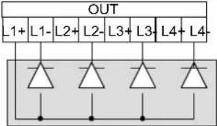 |  |  |
| White, parallel outputs with increased current (Macro dimmer) |  | 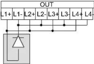 |  | |
 | Tunable White, up to 2 loads |  |  |  |
| Tunable White, parallel output pairs with increased current |  |  |  | |
 | RGB | 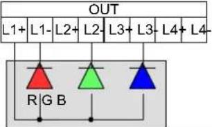 | 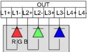 |  |
 | RGBW | 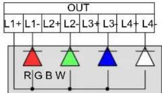 |  |  |
Note: Set the "Select Map" according to the connected load and the function you want. See "Map Setting" page 6.
2) Select Map: Switches from 4 to 6
| White Load Tunable White | Load RGB Load RGBW Load | |||||||
| Dimmer |  | Dimmer |  | Dimmer |  | Dimmer |  | |
| Dim to Warm |  | Dim to Warm |  | Dim to Warm |  | |||
| Tunable White |  | Tunable White |  | Tunable White |  | |||
| Smart HSVIntensity, temperaturecorrection, color hue &rotation, saturation and strobe | Smart HSVIntensity, temperaturecorrection, color hue &rotation, saturation and strobe | |||||||
| RGB | RGBConvert RGB → RGBW | |||||||
| RGBWConvert RGBW → RGB | RGBW | |||||||
| Master+RGB+Strobe | Master+RGB+StrobeConvert RGB → RGBW | |||||||
| Master+RGBW+StrobeConvert RGBW → RGB | Master+RGBW+Strobe | |||||||
3) Select Dimming Curve: Switches from 7 to 8
| Default(by bus type) |  | Exponential |  | Quadratic |  | Linear |  |
4) Select Local Input Type: Switches from 9 to 10
| In Type Description Connections Settings | |||
| Push | N.O. Pushbutton, NO memory |  | |
| N.O. Pushbutton, MEMORY | 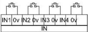 | ||
| 0-10V | Analogic 0-10V |  | |
| 1-10V | Analogic 1-10V & Potentiometer | 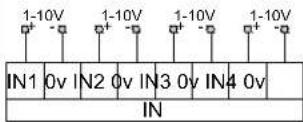 | IN1 0v IN2 0v IN3 0v IN4 0v IN |
5) Set Output Frequency: Switches from 11 to 12
| 300Hz | 600Hz | 1200Hz | Reserved | ||
 |  |  |  | ||
■ Local commands functionality according to the selected Map
| Load Type Map IN 1 IN 2 IN 3 IN 4 | |||||
 White up to 4 loads White up to 4 loads | Dimmer Dim1 Dim2  |  |  |  | |
 White Parallel outs White Parallel outs | Dimmer Dimmer  | ||||
 Tunable White up to 2 loads Tunable White up to 2 loads | Dimmer Dim1 Dim2  |  | |||
| [CXAK]Tunable White Parallel outs | Dimmer Dimmer  | ||||
| [AYST]Tunable White up to 2 loads | Dim to Warm Dim1 to Warm  | Dim2 to Warm  | |||
 Tunable White Parallel outs Tunable White Parallel outs | Dim to Warm Dimmer to Warm  | ||||
 Tunable White up to 2 loads Tunable White up to 2 loads | Tunable White Dim1 CCT1 Dim2 CCT2 | ||||
 Tunable White Parallel outs Tunable White Parallel outs | Tunable White Dimmer CCT | ||||
 RGB & RGBW RGB & RGBW | Dimmer Dimmer | ||||
 RGB & RGBW RGB & RGBW | Dim to Warm Dimmer to Warm | ||||
| [40YY]RGB & RGBW | Tunable White Dimmer CCT | ||||
 RGB & RGBW RGB & RGBW | Smart HSV Dimmer CCT Color Saturation | ||||
| [48W2]RGB & RGBW | RGB Red Green Blue | ||||
 RGB & RGBW RGB & RGBW | RGBW Red Green Blue | White | |||
 RGB & RGBW RGB & RGBW | MRGB+ Red Green Blue | ||||
| [22CH]RGB & RGBW | MRGBW+ Red Green Blue | White | |||
 | LQC4D-V1 4 channelsUser Manual | ||
| Rev. 2018-05-30pag. 8/13 | |||
| ■ LOCAL INPUTSAvailable Functions: N.O. PUSH BUTTON memory / N.O. PUSH BUTTON no memory: | |||
 | DimmerDim the light following the selected dimming curve, keeping a constant color temperature.Soft Turn On with 200ms fade time, Soft Turn Off with 1s fade time.CLICK: Turn ON/OFF light.Double Click: Turn On light at 100%Long pressure (>1s) from OFF: Turn on at 1% (Nighttime)Long pressure (>1s) from ON: Dimmer UP/DOWN | ||
 | Dim to WarmDim the light following the selected dimming curve. The color temperature increase with intensity.Soft Turn On with 200ms fade time, Soft Turn Off with 1s fade time.CLICK: Turn ON/OFF light.Double Click: Turn On light at 100%Long pressure (>1s) from OFF: Turn on at 1% (Nighttime)Long pressure (>1s) from ON: Dimmer UP/DOWN | ||
 | CCT: Color Correction Temperature / White Balance-Tunable White load: change the color temperature, keeping a constant intensity. Neutral white is 50% cold + 50% warm.- RGB load: change the equivalent color temperature. Neutral white is an equal value to R,G,B.- RGBW load: balance the white from the white output to the composite RGB output. Neutral white is 50% white + 50% R+G+B.Double Click: Neutral whiteLong pressure (>1s): Change Colour Temperature UP/DOWN (Cold→Warm or White→R+G+B). | ||
 | Color rotation and selectionChange the color or color rotation speed.CLICK: Start/stop color rotation.Double Click: Change from color (or color rotation) to white and vice-versa.Long pressure (>1s) from ON: Change the rotation speed, selected from 4 predefined levels.The selected speed is visualized as a white strobo light. | Rotation Speed Strobo Pulse6 seconds 10 flashes/sec.30 seconds 5 flashes/sec.6 minutes 2 flashes/sec.30 minutes 1 flash/sec. | |
 | Color saturation:Change the color saturation: vivid colors ↔ pastel colorsCLICK: Toggle between white and colors.Double Click: Maximum saturation - Vivid Colors.Long pressure (>1s) from white: Minimum saturation - Pastel Colors.Long pressure (>1s) from color: Change the saturation value.. | ||
 | Red: linear change red channel.CLICK: Turn ON/OFF channel.Double Click: Turn On channel at 100%Long pressure (>1s) from OFF: Turn on at 1%Long pressure (>1s) from ON: Dim UP/DOWN | ||
 | Green: linear change green channel.CLICK: Turn ON/OFF channel.Double Click: Turn On channel at 100%Long pressure (>1s) from OFF: Turn on at 1%Long pressure (>1s) from ON: Dim UP/DOWN | ||
 | Blue: linear change blue channel.CLICK: Turn ON/OFF channel.Double Click: Turn On channel at 100%Long pressure (>1s) from OFF: Turn on at 1%Long pressure (>1s) from ON: Dim UP/DOWN | ||
 | White: linear change white channel.CLICK: Turn ON/OFF channel.Double Click: Turn On channel at 100%Long pressure (>1s) from OFF: Turn on at 1%Long pressure (>1s) from ON: Dim UP/DOWN | ||
| LQC4D-V1 | LED DRIVERS | ||

LQC4D-V1 4 channels
User Manual
Rev. 2018-05-30
pag. 9/13
Available Functions: 0-10V / 1-10V / potentiometers:

Dimmer
Dim the light following the selected dimming curve, keeping a constant color temperature. Minimum intensity = 0.1%.
Below 1V = Turn OFF light.
10V = Maximum intensity.

Dim to Warm
Dim the light following the selected dimming curve. The color temperature increase with intensity. Minimum intensity = 0.1%.
Below 1V = Turn OFF light.
10V = Maximum intensity.

CCT: Color Correction Temperature / White Balance
-Tunable White load: change the color temperature, keeping a constant intensity. Neutral white is 50% cold + 50% warm.
- RGB load: change the equivalent color temperature. Neutral white is an equal value to R,G,B.
- RGBW load: balance the white from the white output to the composite RGB output. Neutral white is 50% white + 50% R+G+B.
Change the color temperature from warm (1V), to cold (10V).

Color rotation and selection
Change the color.
Select a color starting from red (1V), then yellow, green, cyan, blue, magenta and red again (10V).

Color saturation:
Change the color saturation: vivid colors pastel colors
Change the saturation from white (1V), to vivid colors (10V).

Red: linear change red channel.
Below 1V = Turn OFF channel.
10V = Maximum intensity.

Green: linear change green channel.
Below 1V = Turn OFF channel.
10V = Maximum intensity.

Blue: linear change blue channel.
Below 1V = Turn OFF channel.
10V = Maximum intensity.

White: linear change white channel.
Below 1V = Turn OFF channel.
10V = Maximum intensity.
LQC4D-V1
LED DRIVERS
■ DALI BUS SETUP
In DALI BUS SETUP all the leds are controlled by an external DALI controller.

DALI BUS Reference Standards
| IEC/EN 62386-101 | Digital addressable lighting interface - Part 101: General requirements - System |
| IEC/EN 62386-102 | Digital addressable lighting interface - Part 102: General requirements - Control gear |
| IEC/EN 62386-207 | Digital addressable lighting interface - Part 207: Particular requirements for control gear - LED modules (device type 6) |
Onboard led:
In the case of no bus power detected, or bus error, the led blinks fast (2 pulsed per second).
In the case of bus power but no data, led blinks slow (1 pulse per second).
In the case of data link active, the led stands on.
Relation with local commands
At power-up, in case of absence of connection to the BUS, local control is active.
When the BUS is detected, the control passes to the BUS. It remains to the BUS until there is signal.
In the absence of signal:
- if the local command is N.O. PUSH BUTTON, the control passes to local command in the event of a N.O. push button pressure.
- if the local command is 0-10V or 1-10V the control passes immediately to the local command.
Addressing
| By selectors | √ |
| Simplified method (One ballast connected at a time) | √ |
| Random Address Allocation | √ |
| DALI | 000 (default): | Address defined by DALI | |||
| from 001 | to 064 | First channel address, form 1 to 64 | |||
| FFF | (reserved) | ||||
CHANNELS MAP - DALI

Load Type: White - up to 4 loads
| Addr Function Map: Dimmer | ||
| +0 Dimmer 1 | Dimmer (Brightness Value)0 .. 254 | |
| +1 Dimmer 2 | Dimmer (Brightness Value)0 .. 254 | |
| +2 Dimmer 3 | Dimmer (Brightness Value)0 .. 254 | |
| +3 Dimmer 4 | Dimmer (Brightness Value)0 .. 254 | |

Load Type: White - Parallel outs (Macro dimmer)
| Addr Function Map: Dimmer | ||
| +0 Dimmer | Dimmer (Brightness Value)0 .. 254 | |

Load Type: Tunable White – up to 2 loads
| Addr Function Map: Dimmer | |
| +0 Dimmer 1 | Dimmer (Brightness Value)0 .. 254 |
| +1 Dimmer 2 | Dimmer (Brightness Value)0 .. 254 |
| Addr Function Map: Dim to Warm | ||
| +0 Dimmer 1 | Dimmer (Brightness Value)0 .. 254 | |
| +1 Dimmer 2 | Dimmer (Brightness Value)0 .. 254 | |
| Addr Function Map: Tunable white | ||
| +0 Dimmer 1 | Dimmer (Brightness Value)0 .. 254 | |
| +1 | Color Correction 1 | Color Correction Temperature0 .. 254 |
| +2 Dimmer 2 | Dimmer (Brightness Value)0 .. 254 | |
| +3 | Color Correction 2 | Color Correction Temperature0 .. 254 |

Load Type: Tunable White – Parallel outs
| Addr Function Map: Dimmer | |
| +0 Dimmer 1 | Dimmer (Brightness Value)0 .. 254 |
| Addr Function Map: Dim to Warm | ||
| +0 Dimmer | Dimmer (Brightness Value)0 .. 254 | |
| Addr Function Map: Tunable white | ||
| +0 Dimmer | Dimmer (Brightness Value)0 .. 254 | |
| +1 | Color Correction | Color Correction Temperature0 .. 254 |
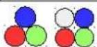
Load Type: RGB & RGBW
| Addr Function Map: Dimmer | ||
| +0 | MasterDimmer | Dimmer (Brightness Value)0 ... 254 |
| Addr Function Map: Dim to Warm | ||
| +0 | MasterDimmer | Dimmer (Brightness Value)0 .. 254 |
| Addr Function Map: Tunable white | ||
| +0 | Master Dimmer | Dimmer (Brightness Value)0 .. 254 |
| +1 | Color Correction | Correction to Correction0 .. 254 |
| Addr Function Smart H$V | |||||||||||||||||
| +0 | Master Dimmer | Master Dimmer (Brightness Value)0 .. 254 | |||||||||||||||
| +1 | Color Correction | color Temperature (mm/second)0 .. 254 | |||||||||||||||
| +2 Hue | Hue0 .. 254 | ||||||||||||||||
| +3 | Hue Rotation (rainbow) Time | Hue Fine0 .. 15 | Hold16 .. 25 | 30min26 .. 51 | 15min52 .. 76 | 6min77 .. 102 | 3min103..127 | 1min128..153 | 30s154..179 | 15s180.204 | 6s205..230 | 3s231..254 | |||||
| +4 | Saturation | Saturation0 .. 254 | |||||||||||||||
| +5 | Strobo Rate | fix0 .. 15 | blackout16 .. 31 | 1fps32 .. 47 | 2fps48 .. 63 | 3fps64 .. 79 | 4fps80 .. 95 | 5fps96 .. 111 | 6fps112..127 | 7fps128..143 | 8fps144..159 | 9fps160..175 | 10fps176..191 | 12fps192..207 | 14fps208..223 | 16fps224..239 | fix240..254 |
| Addr Function Map: RGB | ||
| +0 | R | R 0 .. 254 |
| +1 | G | G 0 .. 254 |
| +2 | B | B 0 .. 254 |
| Addr Function Map: RGBW | ||
| +0 | R | R 0 .. 254 |
| +1 | G | G 0 .. 254 |
| +2 | B | B 0 .. 254 |
| +3 | W | W 0 .. 254 |
| Addr Function Map: MRGB+ | |||||||||||||||||||||
| +0 | Master Dimmer | Master Dimmer (Brightness Value)0 .. 254 | |||||||||||||||||||
| +1 | R | R 0 .. 254 | |||||||||||||||||||
| +2 | G | G 0 .. 254 | |||||||||||||||||||
| +3 | B | B 0 .. 254 | |||||||||||||||||||
| +4 | Strobo Rate | fix | blackout | 1fps | 2fps | 3fps | 4fps | 5fps | 6fps | 7fps | 8fps | 9fps | 10fps | 12fps | 14fps | 16fps | fix | ||||
| Addr Function Map: MRGBW+ | ||||||||||||||||
| +0 | Master Dimmer | Master Dimmer (Brightness Value)0 .. 254 | ||||||||||||||
| +1 | R | R 0 .. 254 | ||||||||||||||
| +2 | G | G 0 .. 254 | ||||||||||||||
| +3 | B | B 0 .. 254 | ||||||||||||||
| +4 | W | W 0 .. 254 | ||||||||||||||
| +5 Stropo Rate | fix | blackout | 1fps 2 | fps 3fps | 4fps 5fps | 6fps | 7fps 8fps | 9fps 10 | fps 12fps | 14fps | 16fps | fix | ||||
DALI COMMANDS
| STANDARD COMMANDS SPECIAL COMMANDS | |
| DIRECT ARC POWER | √ |
| OFF | √ |
| UP | √ |
| DOWN | √ |
| STEP UP | √ |
| STEP DOWN | √ |
| RECALL MAX LEVEL | √ |
| RECALL MIN LEVEL | √ |
| STEP DOWN AND OFF | √ |
| ON AND STEP UP | √ |
| GOTO SCENE (0 to 15) | √ |
| RESET | √ |
| STORE ACTUAL LEVEL IN THE DTR | √ |
| STORE THE DTR AS MAX LEVEL | √ |
| STORE THE DTR AS MIN LEVEL | √ |
| STORE THE DTR AS SYSTEM FAILURE LEVEL | √ |
| STORE THE DTR AS POWER ON LEVEL | √ |
| STORE THE DTR AS FADE TIME | √ |
| STORE THE DTR AS FADE RATE | √ |
| STORE THE DTR AS SCENE (0 to 15) | √ |
| REMOVE FROM SCENE (0 to 15) | √ |
| ADD TO GROUP (0 to 15) | √ |
| REMOVE FROM GROUP (0 to 15) | √ |
| STORE DTR AS SHORT ADDRESS | √ |
| ENABLE WRITE MEMORY | ✕ |
| QUERY STATUS | √ |
| QUERY BALLAST | √ |
| QUERY LAMP FAILURE | √ |
| QUERY LAMP POWER ON | √ |
| QUERY LIMIT ERROR | √ |
| QUERY RESET STATE | √ |
| QUERY MISSING SHORT ADDRESS | √ |
| QUERY VERSION NUMBER | √ |
| QUERY CONTENT DTR | √ |
| QUERY DEVICE TYPE | √ |
| QUERY PHYSICAL MINIMUM LEVEL | √ |
| QUERY POWER FAILURE | √ |
| QUERY CONTENT DTR1 | √ |
| QUERY CONTENT DTR2 | √ |
| QUERY ACTUAL LEVEL | √ |
| QUERY MAX LEVEL | √ |
| QUERY MIN LEVEL | √ |
| QUERY POWER ON LEVEL | √ |
| QUERY SYSTEM FAILURE LEVEL | √ |
| QUERY FADE TIME / FADE RATE | √ |
| QUERY SCENE LEVEL (0 to 15) | √ |
| QUERY GROUPS 0-7 | √ |
| QUERY GROUPS 8-15 | √ |
| QUERY RANDOM ADDRESS H | √ |
| QUERY RANDOM ADDRESS M | √ |
| QUERY RANDOM ADDRESS L | √ |
| READ MEMORY LOCATION | ✕ |
| QUERY EXTENDED VERSION | ✕ |
| TERMINATE | √ |
| DATA TRANSFER REGISTER | √ |
| INITIALIZE | √ |
| RANDOMIZE | √ |
| COMPARE | √ |
| WITHDRAW | √ |
| SEARCHADDR H | √ |
| SEARCHADDR M | √ |
| SEARCHADDR L | √ |
| PROGRAM SHORT ADDRESS | √ |
| VERIFY SHORT ADDRESS | √ |
| QUERY SHORT ADDRESS | √ |
| PHYSICAL SELECTION | ✕ |
| ENABLE DEVICE TYPE | ✕ |
| DATA TRANSFER REGISTER 1 | √ |
| DATA TRANSFER REGISTER 2 | √ |
| WRITE MEMORY LOCATION | ✕ |
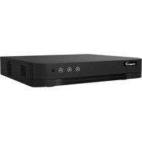
Brand : EtiamPro
Model : LQC4D-V1
Category : Dimmer