
FCC3450 - Multimeter Megger - Free user manual and instructions
Find the device manual for free FCC3450 Megger in PDF.


| Product Type | Bluetooth-enabled flexible current clamp multimeter |
| Model | FCC3450 |
| Brand | Megger |
| AC Current Measurement Range | 30 A, 300 A, 3000 A (auto-ranging) |
| AC/DC Voltage Range | 1000 V AC/DC |
| Resistance Measurement Range | 1000 Ω, 10 kΩ |
| Continuity Threshold | Buzzer sounds < 20 Ω, turns off > 200 Ω |
| Frequency Measurement Range | 100 Hz, 1000 Hz, 10 kHz |
| Maximum Conductor Size | 150 mm (6.0 in) |
| Display | 9999 digit large scale LCD with backlight |
| Bluetooth Version | Bluetooth Low Energy 4.0 |
| Battery Type | 2 x AA (IEC LR6, NEDA 15A) alkaline |
| Battery Life | Typically 60 hours (alkaline) |
| Auto Power Off | After 20 minutes (can be disabled) |
| Dimensions (H x W x D) | 196 mm x 112 mm x 35 mm (excluding coil) |
| Weight (without batteries) | 256 g |
| Safety Rating | CAT IV 600 V, CAT III 1000 V |
| Operating Temperature | -10°C to 50°C (with humidity limits) |
| Storage Temperature | -20°C to 60°C (without batteries) |
| Pollution Degree | 2 |
| Calibration Period | 12 months (recommended) |
| Warranty | 3 years from date of purchase |
| Maintenance | Clean with damp cloth and mild detergent; store without batteries if not used |
| Spare Parts and Repairability | No user-serviceable parts; return to Megger or approved service centre for repair |
Frequently Asked Questions - FCC3450 Megger
User questions about FCC3450 Megger
0 question about this device. Answer the ones you know or ask your own.
Ask a new question about this device
Download the instructions for your Multimeter in PDF format for free! Find your manual FCC3450 - Megger and take your electronic device back in hand. On this page are published all the documents necessary for the use of your device. FCC3450 by Megger.
USER MANUAL FCC3450 Megger
This document is copyright of:
Megger Limited, Archcliffe Road, Dover, Kent CT17 9EN. ENGLAND T +44 (0)1304 502101 F +44 (0)1304 207342 www.megger.com
Megger Ltd reserves the right to alter the specification of its products from time to time without notice. Although every effort is made to ensure the accuracy of the information contained within this document it is not warranted or represented by Megger Ltd. to be a complete and up - to - date description.
For Patent information about this instrument refer to the following web site: megger.com/patents
This manual supersedes all previous issues of this manual. Please ensure that you are using the most recent issue of this document. Destroy any copies that are of an older issue.
Declaration of Conformity
Hereby, Megger Instruments Limited declares that radio equipment manufactured by Megger Instruments Limited described in this user guide is in compliance with Directive 2014/53/EU. Other equipment manufactured by Megger Instruments Limited described in this user guide is in compliance with Directives 2014/30/EU and 2014/35/EU where they apply.
The full text of Megger Instruments EU declarations of conformity are available at the following internet address:
megger.com/company/about-us/eu-dofc
1. Introduction
This instruction manual contains information regarding the correct use and handling of the FCC3450. Please ensure to consult the chapter 'Safety warnings and standards'. This chapter contains information regarding your personal safety when using the product.
1.1 Product description
The Megger FCC3450 is a Bluetooth® enabled flexible current clamp, designed to make AC/DC voltage, frequency, continuity and resistance measurements, as well as AC current up to 3000 A.
1.2 Features
■ Up to 3000 A AC current measurement
1000 V AC/DC measurement
150 mm maximum conductor size
■ Megger Linkapp compatible
■ Continuity and frequency measurement
Data hold on all ranges
■ Low battery LED indicator
CAT IV 600 V/CAT III 1000 V supplied with protective carry pouch
1.3 Applications
The FCC3450 is a CAT IV/600 V rated flexible current clamp, measuring up to 1000 V AC/DC and up to 3000 A AC.
Due to the length and flexibility of the coil, measurements can be made around large conductors, or those conductors inaccessible to a fixed-head clamp.
Pairing with the free Megger Link™ app give the user the ability to make remote rreadings or record measurements directly to their smart device for storage or report creation.
1.4 Company web site
Occasionally an information bulletin may be issued via the Megger web site. This may concern new accessories, new usage or user instructions or a software update. Please occasionally check on the Megger web site for anything applicable to your Megger instruments.
www.megger.com
2. Safety Warnings and Standards
These safety warnings must be read and understood before the instrument is used. Please retain for future reference.
To ensure safe operation and service of the FCC3450, follow these instructions. Failure to observe warnings can result in severe INJURY or DEATH.
2.1 Warnings, Cautions and Notes
This user guide follows the internationally recognised definition. These instructions must be adhered to at all times.
| Description |
| WARNING: Indicates a potentially dangerous situation which, if ignored, could lead to death, serious injury or health problems. |
| ATTENTION: Indicates a dangerous situation which, if ignored, could lead to injuries or health problems. |
| CAUTION: Indicates a situation which could lead to damage of the equipment or environment |
| NOTE: Indicates important instructions to be followed to perform the relevant process safely and efficiently. |
2.2 Safety warnings
If the equipment is used in a manner not specified by the manufacturer, the protection provided by the equipment may be impaired.
■ To reduce the risk of fire or electric shock, do not use this product around explosive gas or in damp locations.
- Verify the Meter operation by measuring a known resistance, voltage and current. If in doubt, have the Meter serviced.
Do not apply more than the rated voltage - as marked on the Meter - between the terminals or between any terminal and earth.
To avoid inaccurate of false readings that may lead to an electric shock or injury, replace the battery as soon as the 10% battery life is shown, or the low battery symbol appears.
- Avoid working alone.
Do not use the FCC3450 if it is not operating correctly or if it is wet.
■ When using the FCC3450, the test leads or the probes/crocodile clips, always keep you fingers behind the finger/hand guards.
■ Use caution with voltages above 30 Vac rms, 42 Vac peak, or 60 Vdc. These voltages pose a shock hazard.
■ Remove the flexible coil from any conductor and the leads from both terminals before opening the battery door to replace batteries.
Safety Warnings and Standards
■ DO NOT USE the test leads if they appear damaged or the internal white insulation layer is exposed.
■ DO NOT USE the test leads, probes or crocodile clips in any environment above their maximum category rating.
■ DO NOT USE the test leads without the probe tip guard cap in CAT III and CAT IV environments.
■ Probe assemblies to be used for MAINS measurements shall be RATED as appropriate for MEASUREMENT CATEGORY III or IV according to IEC 61010-031 and shall have a voltage RATING of at least the voltage of the circuit to be measured.
■ Disconnect the circuit power and discharge all high voltage capacitors before testing resistance or continuity.
■ DO NOT USE the flexible current sensor if the insulation appears damaged or the inner copper wire is visible.
■ De-energize the installation under test when fitting and removing the Flexible Current Probe.
■ Do not apply around or remove from UNINSULATED HAZARDOUS LIVE conductors.
Do not open the instrument case, there are no user serviceable parts inside. In the event of a fault, return the FCC3450 to Megger or an Approved Service Centre.
CAUTION : Identify conditions and actions that could damage the FCC3450, the equipment under test, or cause permanent loss of data.
- Remove the batteries if the FCC3450 will not be used for an extended period of time, or if storing in temperatures above 50 °C. If the batteries are not removed, battery leakage may damage the FCC3450.
- Do not expose the FCC3450 to extremes of temperature or high humidity.
NOTE : The instrument must only be used by suitable trained and competent persons
Installation category definitions:
CAT IV - Measurement category IV: Equipment connected between the origin of the low-voltage mains supply and distribution panel.
CAT III -Measurement category III: Equipment connected between the distribution panel and electrical outlets.
CAT II - Measurement category II: Equipment connected between the electrical outlets and user's equipment.
Measurement equipment may be safely connected to circuits at the marked rating or lower. The connection rating is that of the lowest rated component in the measurement circuit.
2.3 Safety, Hazard and Warning symbols on the instrument
This table details the various safety and hazard icons on the instrument's outer case.
| Icon Description | |
 | Warning: High Voltage, risk of electric shock |
 | Caution: Refer to user guide. |
 | Do not apply or remove the clamp from HAZARDOUS LIVE conductors |
 | AC (Alternating Current or Voltage) |
 | DC (Direct Current or Voltage) |
 | Both AC and DC |
 | IEC Overvoltage CategoryCAT III equipment is designed to protect against transients in equipment in fixed equipment installations, such as distribution panels, feeders and short branch circuits, and lighting systems in large buildings.CAT IV equipment is designed to protect against transients from the primary supply level, such as an electricity Meter or an overhead or underground utility service. |
 | Reference earth connection. Not a protective earth terminal |
| [SxK5] | Equipment protected throughout by double insulation. |
 | Battery capacity |
 | Bluetooth |
 | UK conformity. This equipment complies with current UK directives |
 | EU conformity. Equipment complies with current EU directives. |
 | Do not dispose of in the normal waste stream. |
3. Instrument Overview
3.1 Instrument layout

| Item Description Item Description | ||
| 1 Clamp lock mechanism 4 V-Ω input terminal | ||
| 2 LCD display 5 COM input terminal | ||
| 3 Function buttons 6 Work light |
3.2 Instrument display

| Item Description Item Description | ||
| 1 Meter status symbols 4 Function unit symbols | ||
| 2 Battery capacity symbol 5 Hold symbol | ||
| 3 Primary measurement 6 Secondary measurement |
4. Operation
4.1 Power On / Off

Press and hold the on/off button for longer than 2 seconds. When turning on, the display indicates the current battery capacity. The battery must be replaced if 10% or less is shown to avoid false or inaccurate readings.
4.2 Auto Power Off (APO)

Auto power Off is turned on by default and APO is shown on the display. If there is no user input, the FCC3450 will auto power off after 20 minutes.
4.3 Disable Auto Power Off
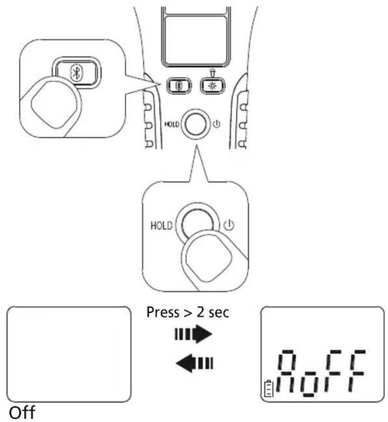
To disable Auto Power Off, push and hold the Bluetooth button when turning the FCC3450 on. When AoFF appears on the LCD, release both buttons. The APO symbol on the display should not be visible.
4.4 Input Selection
The FCC3450 prioritises any terminal input measurement over the flexible coil current measurement.
The meter will default to show a voltage, resistance or continuity measurement if connected to the input terminals when making a current measurement.
Removing any terminal input will cause the FCC3450 to return to displaying the measured current value, if present.
4.4.1 AC Current Measurement
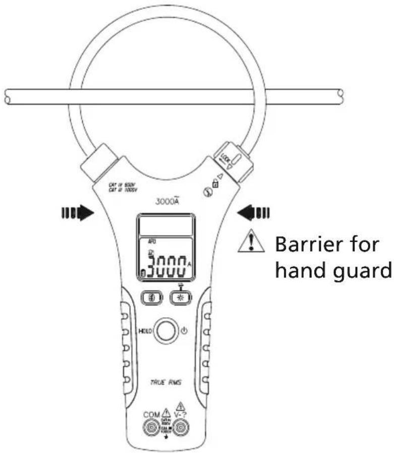
WARNING : The barrier on the JAW (indicated below) defines the limit of safe access of the hand held part of the meter. Do not place hands past the barrier when in normal use.
4.4.2 Unlock / Lock Flexible Coil

Turn the clamp lock counter-clockwise to release the flexible clamp. Place the flexible clamp around a single conductor only.
Insert the flexible clamp back in the clamp lock and turn clockwise to secure. Check that the flexible clamp is secure before making any measurement.
4.4.3 Position Error

For maximum accuracy, the single conductor should be positioned in the center of the flexible clamp where possible. See detailed specification for position accuracy error.
4.5 Voltage, Resistance and Continuity
WARNING: When connecting the test leads, always connect the common test lead before connecting the live test lead. When removing the test leads, remove the live test lead before removing the common test lead.
WARNING : Do not use the FCC3450 to measure voltages in circuits that could be damaged by the meters LoZ mode low impedance (approx. 4 kΩ).

NOTE : During a continuity measurement, the built-in buzzer sounds when measured resistance is less than 20 Ω and turns off when measured resistance is greater than 200 Ω. Between 20 Ω to 200 Ω the buzzer may still sound.
4.6 Data Hold

Data Hold can be used to retain the displayed values on any range. To turn on Data Hold, briefly press the Data Hold button. To return to normal measurement mode, press the Data Hold button a second time. H is shown in the display when Data Hold is active.
4.7 Bluetooth®

The FCC3450 uses low-power Bluetooth® v4.0 wireless technology to transfer real-time data. To use the communication link on Android or iOS devices, install the Megger Link™ App.
| Megger LinkTM on Apple App Store | Megger LinkTM on Google Play | |
 |  | Download the “Megger LinkTM” App. Turn on the Bluetooth function of the meter by pressing the Bluetooth button and open the Megger LinkTM App to connect the DCM. |
 |  | The Bluetooth icon of the meter will flash whilst connecting and freeze on the LCD after the connection is established. |
Max. communication range: Open air up to 10 m
4.8 Backlight
Press the yellow backlight button once to turn the display backlight on or off.
4.9 Work light
Press and hold the yellow backlight button for >1sec to turn the work light on or off.
4.10 Battery Replacement
Remove the FCC3450 from any measurement circuit and remove all test leads before opening battery cover.

Batteries MUST be replaced as soon as 10% battery capacity is reached.
5. Specifications
5.1 General Specifications
LCD display digits: 9,999 digit large scale LCD readout
Overload display: OL or -OL
Battery Type: 2 Batteries, IEC LR6, NEDA 15 A, Alkaline (AA)
Battery Life: Typically 60 hours (Alkaline)
Auto Power Off: The Meter automatically turns off after 20 minutes if no buttons are pressed.
Max. Conductor Size: approx. 150 mm / 6.0"
Dimensions (H x W x D): 196 mm (excluding coil) x 112 mm x 35 mm
Weight (without batteries): 256 g
5.2 Environmental Conditions
Temperature Coefficient: 0.1 x (specified accuracy) / °C (<18°C or >28°C)
Operating Temperature: -10°C to 30°C (≤ 80% R.H.)
30^ to 40^ ( ≤ 75% R.H.)
40^ to 50^ (≤ 45% R.H.)
Storage Temperature: -20°C to 60°C (≤ 80% R.H., no batteries)
Max. Operating Altitude: 2000m (6562 ft.)
Drop Protection: 1.2 m drop to hardwood on concrete floor
Vibration: Random Vibration per MIL-PRF-28800F Class 2
Recommended calibration
period: 12 Months
Indoor Use Only
5.2.1 Safety Standards:
IEC / EN 61010-1
EN 61010-2-032
EN 61010-2-033
CATIV 600 V, CATIII 1000 V
Pollution Degree 2
5.2.2 Electromagnetic Compatibility Standards (EMC):
EN 61326-1
5.2.3 Wireless Communications
Bluetooth® Low Energy (4.0)
■ Radio Frequency: 2.4 GHz ISM Band
■ Effective range: Open air 10 m
5.3 Electrical Specifications
Accuracy is given as ± (% of reading + counts of least significant digit) at 23^ C ± 5°C ( ≤ 80% R.H.)
5.3.1 AC Function
■ ACV and ACA specifications are AC coupled, True RMS.
■ For non-sinusoidal waveforms, adjust accuracy by Crest Factor (C.F.):
- Add 1.0% for C.F. 1.0 to 2.0
■ Add 2.5% for C.F. 2.0 to 2.5 - Add 4.0% for C.F. 2.5 to 3.0
5.3.2 Max. Crest Factor of Input Signal:
| Range Max. Crest Factor Limit | ||
| 30 A | 3.0 ≤ 1500 counts | |
| 300 A | 2.0 ≤ 2250 counts | |
| 3000 A | 1.5 ≤ 3000 counts | |
| 1000 V 3.0 ≤ 5000 counts | ||
| 2.0 ≤ 7500 counts | ||
| 1.5 ≤ 9999 counts | ||
Frequency Response is specified for a sinewave waveform.
5.3.3 AC Ampere
| Range Resolution Accuracy | |
| 30 A* 0.01 A ±(3.0%+5D) | |
| 300 A 0.1 A ±(3.0%+5D) | |
| 3000 A 1 A ±(3.0%+5D) |
* Minimum Reading is 1.00 A
Frequency Response : 45 Hz to 500 Hz
Overload Protection : 3000 A
5.3.4 Position Error of Clamp
| Model Distance from optimum | Accuracy |
| FCC3450 35 mm/1.4" ±1.0% | |
| 50 mm/2.0" ±1.5% | |
| 60 mm/2.4" ±2.0% |
5.3.5 Voltage
| Function Range | Resolution | Accuracy | |
| AC | 1000 V* | 0.1 V | ±(1.5%+5D) |
| DC | 1000 V** | 0.1 V | ±(0.7%+5D) |
* Minimum Reading is 3.0 V
** Minimum Reading is +2.4 V / -0.7 V
AC Frequency Response: 45 Hz to 500 Hz
Input Impedance: >4 kΩ for input voltage up to 30 V, impedance increases to >375 kΩ with an input voltage up to 1000 V.
Maximum Operation Time : DT = 30 sec for > 30 V
Overload Protection: AC / DC 1000 V
5.3.6 AC Frequency
| Range Resolution Accuracy | |
| 100 Hz* 0.1 Hz ±(0.3%+3D) | |
| 1000 Hz 1 Hz ±(0.3%+3D) | |
| 10 kHz 0.01 kHz ±(0.3%+3D) |
* Minimum Reading is 10 Hz
5.3.7 Minimum Sensitivity :
AC A: Reading > 3 A at 40 Hz to 1 kHz, > 6 A at < 40 Hz or > 1 kHz
AC V: Reading > 10 V at 40 Hz to 1 kHz, > 20 V at < 40 Hz or > 1 kHz
5.3.8 Resistance / Continuity
| Range Resolution Accuracy | ||
| 1000 Ω 1 Ω ±(0.9%+2D) | ||
| 10 kΩ | 0.001 kΩ | ±(0.9%+2D) |
Continuity Indicator : Built-in buzzer sounds when measured resistance is less than 20 Ω and turns off when measured resistance is greater than 200 Ω. Between 20 Ω to 200 Ω the buzzer may still sound.
Response Time of Buzzer: < 1 ms
Maximum Output Voltage: 2.1 V
Overload Protection: AC / DC 1000 V
5.3.9 Measuring Rate and Response Time
| Function | Measuring Rate | Response Time |
| V / Ω | 2 sample(s) per sec | 2 sec |
| A | 1 sample(s) per sec | 2 sec |
| Hz | 3 sample(s) per sec | 2 sec |
Maintenance.
6. Maintenance.
6.1 Maintenance
Do not attempt to repair this clamp meter. It contains no user-serviceable parts. Repair or servicing should only be performed by qualified personnel. To maintain the best accuracy, calibrate the FCC3450 once per year.
6.2 Cleaning
Periodically wipe the case with a damp cloth and mild detergent, do not use abrasives or solvents. Ensure the case is completely dry before use.
6.3 Storage
Remove the batteries if the FCC3450 is not used for an extended period of time or if storing in temperatures above 50^ C. If the batteries are not removed, they may leak and damage the FCC3450.
7. Decommissioning
7.1 WEEE Directive
The crossed out wheeled bin symbol placed on Megger products is a reminder not to dispose of the product at the end of its life with general waste.
Megger is registered in the UK as a Producer of Electrical and Electronic Equipment. The Registration No is WEE/ HE0146QT.
For further information about disposal of the product consult your local Megger company or distributor or visit your local Megger website.
7.2 Battery disposal
The crossed out wheeled bin symbol placed on a battery is a reminder not to dispose of batteries with general waste when they reach the end of their usable life.
For disposal of batteries in other parts of the EU contact your local Megger branch or distributor.
Megger is registered in the UK as a producer of batteries (registration No.: BPRN00142).
For further information see www.megger.com
7.3 Warranty (3 years)
This Meter is warranted to the original purchaser against defects in material and workmanship for 3 years from the date of purchase.
During this warranty period, the manufacturer will, at its option, replace or repair the defective unit, subject to verification of the defect or malfunction.
This warranty does not cover disposable batteries, or damage from abuse, neglect, accident, unauthorized repair, alteration, contamination, or abnormal conditions of operation or handling.
Any implied warranties arising out of the sale of this product, including but not limited to implied warranties of merchantability and fitness for a particular purpose, are limited to the above.
The manufacturer shall not be liable for loss of use of the instrument or other incidental or consequential damages, expenses, or economic loss, or for any claim or claims for such damage, expense or economic loss.
Some states or countries laws vary, so the above limitations or exclusions may not apply to you.
Local Sales office
Megger Limited
Archcliffe Road
Dover
Kent
CT17 9EN
ENGLAND
T.+44 (0)1 304 502101
F. +44 (0)1 304 207342
Manufacturing sites
| Megger Limited | Megger GmbH | Megger USA - Valley Forge |
| Archcliffe Road | Weststraße 59 | Valley Forge Corporate Center |
| Dover | 52074 Aachen | 2621 Van Buren Avenue |
| Kent | T. +49 (0) 241 91380 500 | Norristown |
| CT17 9EN | E. info@megger.de | Pennsylvania, 19403 |
| ENGLAND | USA | |
| T. +44 (0)1 304 502101 | T. +1 610 676 8500 | |
| F. +44 (0)1 304 207342 | F. +1 610 676 8610 | |
| Megger USA - Dallas | Megger AB | Megger USA - Fort Collins |
| 4545 West Davis Street | Rinkebyvägen 19, Box 724, SE-182 17 | 4812 McMurry Avenue |
| Dallas TX 75237 | Suite 100 | |
| USA | DANDERYD | Fort Collins CO 80525 |
| T. 800 723 2861 (USA only) | T. +46 08 510 195 00 | USA |
| T. +1 214 333 3201 | E. seinfo@megger.com | T. +1 970 282 1200 |
| F. +1 214 331 7399 | ||
| E. USsales@megger.com |
This instrument is manufactured in the Taiwan.
The company reserves the right to change the specification or design without prior notice.
Megger is a registered trademark
The Bluetooth® word mark and logos are registered trademarks owned by Bluetooth SIG, Inc and is used under licence.
FCC3450_UG_en_V01 02 2022
© Megger Limited 2020 www.megger.com

- This document is copyright of:
- Declaration of Conformity
- Introduction
- Product description
- Features
- Applications
- Company web site
- Safety Warnings and Standards
- Warnings, Cautions and Notes
- Safety warnings
- Safety Warnings and Standards
- CAUTION : Identify conditions and actions that could damage the FCC3450, the equipment under test, or cause permanent loss of data.
- Installation category definitions:
- Safety, Hazard and Warning symbols on the instrument
- Instrument Overview
- Instrument layout
- Operation
- Power On / Off
- Auto Power Off (APO)
- Disable Auto Power Off
- Input Selection
- AC Current Measurement
- Unlock / Lock Flexible Coil
- Position Error
- Voltage, Resistance and Continuity
- Data Hold
- Bluetooth®
- Backlight
- Work light
- Battery Replacement
- Specifications
- General Specifications
- Environmental Conditions
- Safety Standards:
- Electromagnetic Compatibility Standards (EMC):
- Wireless Communications
- Electrical Specifications
- AC Function
- Max. Crest Factor of Input Signal:
- AC Ampere
- Position Error of Clamp
- Voltage
- AC Frequency
- Minimum Sensitivity :
- Resistance / Continuity
- Measuring Rate and Response Time
- Maintenance.
- Maintenance
- Cleaning
- Storage
- Decommissioning
- WEEE Directive
- Battery disposal
- Warranty (3 years)
- Local Sales office
Brand : Megger
Model : FCC3450
Category : Multimeter